VOL.. l, NO. 3. JULY SEPTElllRER 1974€¦ · 7th Unit -21 -114 -0824 -83 -211 -6684 8th Unit -23...
24
VOL.. l, NO. 3. JULY SEPTElllRER 1974 Sile<o!W i'tin1i1"40etob<:T 197] A SERVICE PU BLICi\ T I ON OF L OC KH EEO· GEORGIA COMP1-\N Y, A DIVISI ON OF L OCl<l-IEED AIRCRAFT CORPORATION
Transcript of VOL.. l, NO. 3. JULY SEPTElllRER 1974€¦ · 7th Unit -21 -114 -0824 -83 -211 -6684 8th Unit -23...

VOL.. l, NO. 3. JULY SEPTElllRER 1974 Sile<o!W i'tin1i1"40etob<:T 197]
A SERVICE PUBLICi\ TION OF LOCKHEEO·GEORGIA COMP1-\NY, A DIVISION OF LOCl<l-IEED AIRCRAFT CORPORATION

A SERVICE PUBLICATION OFLOCKHEED-GEORGIA COMPANYA DIVISION OFLOCKHEED AIRCRAFT CORPORATION
EditorJay V. Roy
Associate EditorJames A. Loftin
Art Direction & ProductionPhillip E. Evans
Vol. 1, NO. 3, July- September 1974
CONTENTS
2 Troubleshooting6 Tank Units Part Numbers and Capacitance
10 Troubleshootmg Chart
I5 Fuel Weight To Capacitance
16 Connec to rs
I8 Delayed Maintenance. Can Give Youa Blast
20 How JetStars Keep Their COOL
StarTips
15
23
Two Different Hercules Engine Driven
Hydraulic PumpsHow the 1867th FCS Licked a TurbineProblem
Hercules Fuel Quantity IndicatingSystem
COVER: A Lockheed Flight Test crew boards aCanadian Armed Forces Hercules for an earlymorning takeoff.
Published by Lockheed-Georgia Company, a Division ofLockheed Aircraft Corporation. Information contained inthis issue is considered by Lockheed-Georgia Company tobe accurate and authoritative; it should not be assumed,however, that this material has received approval from anygovernmental agency or military service unless ii isspecifically noted. This publication is for planning andinformation purposes only, and it is not to be construedas authority for making changes an aircraft or equipmentor as superseding any established operational ormaintenance procedures or policies. The following marksare registered and owned by Lockheed AircraftCorporation: “ “, “Lockheed”, “Hercules”, and"JetStar" Written permission must be obtained fromLockheed-Georgia Company before republishing anymaterial in thin periodical. Address all communications toEditor, Service News, Department 64-22, Zone 278,Lockheed-Georgia Company, Marietta, Georgia 30063.Copyright 1974 Lockheed Aircraft Corporation.
Troubleshootingthe Hercules Fuel Quantity
by HAROLD COOK, Senior Functional Test Engineer andELBERT FIELDS, Service Analyst
WE’RE GOING to look at, specifically, the fuel quantity indicating system installedon C-130B and subsequent Hercules aircraft. But the general information isapplicable to all capacitance-type indicating systems, such as those on the C-130Aand the JetStar.
Troubleshooting a fuel quantity indicating system requires strict adherence to all ofthe safety precautions concerning such matters as fueling and defueling, open fueltanks and proper test equipment. As a supplement to these safety precautions, thefollowing procedures are recommended for troubleshooting the Hercules fuelquantity indicating system:
Do not use electrical equipment capable of producing more than 200 milliamperes infuel tank measurements. Use only the MD-2A (FSN/4920-509-1508) automaticcapacitance bridge and low-voltage megohmmeter (megger) or TF-20(FSN/4920-962-3027) automatic capacitance bridge, low-voltage megger, andprecision capacitors for all capacitance and resistance measurements.
With system or test equipment power applied to the fuel quantity indicating system(tanks not drained and purged), do not make or break any electrical connections in,or close to, the fuel tanks. Any connections required for continuity checks should bemade with or TF-20 test equipment de-energized. Energize test equipmentonly after all connections are completed to verify continuity. De-energize testequipment prior to disconnecting.
CAUTION: Do not apply power to the aircraft while fuel tank is open.
Any equipment used in testing or measuring fuel quantity indicating systemcomponents should be grounded to the aircraft and/or static ground prior toapplying power to the equipment. Ground connections should not be assumed, theyshould be checked.
The Hercules fuel quantity indicating system is a single-point ground system. Onsome aircraft the shield of the coaxial cable is grounded only through the indicator,while on production aircraft LAC 4454 and subsequent and in-service aircraftmodified in accordance with Service Bulletin 82-308 or 382-144 the ground isthrough the aircraft structure near the indicator. The system is not grounded in thetank. Depending on configuration, the shield may be above ground when theindicator is disconnected. In addition, the case of the MD-2A or TF-20 has the sameground potential as the shield. This means that when one of these testers is beingused to check the system, either in the cockpit or at the tank boundary (the point atwhich the wiring enters the tank) and the ground wire for the MD-2A or TF-20 is notconnected, any voltage on the case of the tester (internal short in MD-2A or TF-20,voltage on stand contacting case of the test equipment,etc.) may be applied directlyto the shield of the coaxial cable inside the tank. Always ground the MD-2A orTF-20 to the aircraft structure prior to applying power to the test equipment.


FIGURE 1
CONNECTION OF MD-2A
4
Check power source for proper voltage (specified inhandbook or on test equipment) before connecting testequipment to power source.
Any equipment in contact with the MD-2A or TF-20,such as the stand, should also be grounded to the aircraftand/or static ground.
Do not use ohmmeters with unknown current capabilitiesfor resistance checks on the fuel quantity indicatingsystem. Use only MD-2A or TF-20.
Do not use high-potential tester or megger. Use onlyMD-2A or TF-20.
Operations such as soldering should not be performedaround the fuel tanks before draining and purging hasbeen accomplished.
Static-producing clothing should not be worn whenworking around fueling and defueling operations.
TROUBLESHOOTING . Reports of malfunctions inthe fuel quantity indicating system will usually beexpressed in terms of indicator performance. Examples:indicator drives to below zero indicator shifts up scaleor down scale in error (1000 lb., 2000 lb., etc.) indicator is inoperative .
Although a troubleshooting chart is included, let’s look atthe more common malfunctions as an aid in using thechart.
MALFUNCTION: INDICATOR IS AGAINST THE STOPBELOW ZERO WITH FUEL IN THE TANK
The most common causes, and tbeir remedies are:
Center conductor of coaxial cable shorted to shieldanywhere in the system, or internally shorted tank unit.
Open the circuit breaker for the system being tested,disconnect the cockpit indicator, and connect thecalibration harness and MD-2A or TF-20 per Figure 1 orFigure 2.
CAUTION: Connect ground wire from MD-2A or TF-20per Figure 1 or Figure 2 before connecting topower source.
NOTE: Only the MD-2A will be referred to in thefollowing tests. See “How to Use the TF-20” appearinglater if this tester is to be employed.
Connect the MD-2A to 115V, 400 Hz power, and positionpower switch to ON. Allow approximately five minutesfor warm-up.
Calibrate the megohmmeter with the MegohmmeterRange Selector in both CAL positions then position theMegohmmeter Range Selector to Xl.
Using the Capacitance-Megohms Selector (MD-2A), checkthe resistance for the A TO CRD (coaxial cable centerconductor to GRD) position. The total system resistanceshould be within the limits of Table 1.
If the resistance reading is not less than the value shown inTable 1 (Approximate total sytem resistance beforeindicator accuracy is affected), the cause is neither thecenter conductor shorted to the shield nor an internally
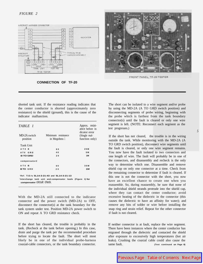
FIGURE 2
CONNECTION OF TF-20
shorted tank unit. If the resistance reading indicates thatthe center conductor is shorted (approximately zeroresistance) to the shield (ground), this is the cause of theindicator malfunction.
TABLE 1 Approx. resist-ance before indicator error
MD-2A switch Minimum resistance (Single mal-position in Megohms 1 function only)
Tank UnitA T 0 B 6 0 2 5 M
A T 0 G R D 4 0 5 M
B TO GRD 2 0 1M
c o m p e n s a t o r 2
A T 0 B 6 0 3 0 M
B TO G R D 2 0 1M
‘Ref . T.O.‘s 5L14-3-21-43 and 5L14-3-21-13
‘Interchange tank unit and-compensator leads (Figure 1) for
compensator circuit check.
With the MD-2A still connected to the indicatorconnector and the power switch (MD-2A) to OFF,disconnect the connector(s) at the tank boundary for thetank system under test. Position MD-2A power switch toON and repeat A TO GRD resistance check.
If the short has cleared, the trouble is probably in thetank. (Recheck at the tank before opening.) In this case,drain and purge the tank per the recommended procedurebefore trying to locate the fault. The short will mostlikely be in one of the individual probe-harnesscoaxial-cable connectors, or the tank boundary connector.
The short can be isolated to a wire segment and/or probeby using the MD-2A (A TO GRD switch position) anddisconnecting segments of probe wiring, beginning withthe probe which is farthest from the tank boundaryconnector(s) until the fault is cleared or only one wiresegment is left. (NOTE: Reconnect each segment as thetest progresses.)
5
If the short has not cleared, the trouble is in the wiringoutside the tank. While monitoring with the MD-2A (ATO GRD switch position), disconnect wire segments untilthe fault is cleared, or only one wire segment remains.You now have the fault isolated to two connectors andone length of wire. The fault will probably be in one ofthe connectors, and disassembly and recheck is the onlyway to determine which one. Disassemble and removeshield cup on only one connector at a time. Check fromthe remaining connector to determine if fault is cleared. Ifthis one is not the connector with the short, you nowhave an excellent chance to create one when youreassemble. So, during reassembly, be sure that none ofthe individual shield strands protrude into the shield cap,where they can contact the center conductor; avoidexcessive heating of the dielectric in the connector (thiscauses the dielectric to have an affinity for water); andremove any bits of solder or wire before installing thesnap ring and strain relief. Repeat for the other connectorif fault is not cleared.
If neither connector is at fault, replace the wire segment.There have been instances where the center conductor hasmigrated through the dielectric and contacted the shieldafter exposure to excessively high temperatures (hot airleaks). Crushing the coaxial cable could also cause thesame fault. (Text continued on Page 8)

TANK ORIGINAL
Lockheed P/N Vendor P/N
MOD I
FSN Lockheed P/N Vendor P/N FSN
1st Unit 695799-1 FG220A-97 6680-585-9354 695799-63 FG220A-194 6680-05 I-66932nd Unit -3 -96 -9363 -65 -193 -66943rd Unit -5 4 5 -9352 -67 -192 -6691Compensator -7 FG260A-6 -0827 -69 FG250A-42 -089-5300
Bladder(Auxiliary)
1st Unit 695799-9 FG220A-108 6680-585-9350 695799-71 FG220A-205 6680-051-67022nd Unit -11 -109 -0811 -73 -206 -66903rd Unit -13 -110 -0820 -75 -207 -67004th Unit -15 -111 -082 1 -77 -208 -66875th Unit -17 -112 -0822 -79 -209 -66866th Unit -19 -113 -0823 -81 -210 -66867th Unit -21 -114 -0824 -83 -211 -66848th Unit -23 -1 16 -9351 -85 -212 -6699Compensator -25 FG205A-7 -0828 -87 FG250A-43 -089-529s
Inboard
6 Outboard 1st Unit 695799-27 FG220A-98 6680-585-0825 6 9 5 7 9 9 8 9 FG220A-195 6680-051-6683-29 -99 -0826 -91 -196 -8849-31 -100 -0817 -93 -197 -6688-33 -101 -1038 -95 -198 -6692-35 -102 -0816 -97 -199 -6698-37 -103 -9349 -99 -200 -6697-39 -104 -0815 -101 -201 -6696-41 -105 -08 14 -103 -202 -6689-43 -106 -0813 -105 -203 -6695-45 -107 -0812 -107 -204 -6701-47 FG250A-8 -0810 -109 FG250A-44 -089-5298
2nd Unit3rd Unit4th Unit5th Unit6th Unit7th Unit8th Unit9th Unit
10th UnitCompensator
Lock heed
Pylon(External)
1st Unit Center 695799-49 FG220A-178 6680-899-8663 695799-l 11 FG220A-215 6680-056-95422nd Unit Center -51 -179 8 6 6 4 -113 -216 -9543
Aft Section -53 -177 -8662 -115 -214 -9541
Fwd Section -55 -176 8661 -117 -213 -9540
Compensator -57 FG6B-1 -853-1233 -119 FG6B-2 -071-3968
American 1 st Unit Center None EA772-2856 6680-869-9811Electric 2nd Unit Center None -2867 -9812Pylon Aft Section None -2858 -9613(External) Fwd Section None -2859 -9814
compensator None 6 1115.2860 -9810
1 Same as ORIGINAL except inner electrodes and compensators have a coating to resist the effects of contaminants in the fuel.
‘Same as MOD I except equipped with new connectors per MIL-C-255166 and internal wiring improvements. This configurationinstalled as a part of TCTO 741, and is the preferred replacement.

MOD II2 DRY CAPACITANCE IN MMF
Lockheed P/N Vendor P/N FSN Tank Unit Compensator
FG220A-239 6 6 8 0 - 9 6 8 - 3 2 2 7 50.8-52.8-238 -3226 27.3-28.9-237 -3225 57.7-60.1
FG25OA-51 -3277 30.2-31.8 29.5-31.1
695799-l 21-123-125-127
Empty 169.8 (166.4-173.5) 30.3Added 188.0 * 31.7
Full 357.8 Jic 62.0
695799-1 29 FG220A-250 6680-968-3260-131 -251 -3261-133 -252 -3263-135 -253 -3266-137 -254 -3269-139 -255 -3270-141 -256 -327 1-143 -257 -3273-145 FG250A -52 -3278
27.0-28.63 1.2-32.833.0-34.632.1-33.733.6-35.231 .O-32.626.4-28.028.2-29.86.7-8.3256.4 (251.3-261.5)291.2*
29.5-31.130.331.7
EmptyAdded
Full 547.6 * 62.0
710.2-I 1.818.2-19.824.7-26.319.7-21.3
14.7-16.3
13.2-14.8
13.7-15.3
26.7-28.3
3 1.6-33.2
27.2-28.8
5.0-6.6
213.7 (209.4-218.0)
241.6 *
695799-147 FG220A-240 6680-968 -3228-149 -241 -3229-151 -242 -3230-153 -243 -3242-155 -244 -3243-157 -245 -3247-159 -246 -3251-161 -247 -3252-163 -248 -3255-165 -249 -3258-167 FG25OA-53 -328 1 29.5-31.1
30.331.7
EmptyAdded
Full 455.3 * 62.0
84.2-85.881.7-83.3
80.2-81.88 1.4-83.0330.7 (324.1-337.3)391.2 *
695799-169 FG22OA-260 6680-968 -32 13-171 -261 -3223-173 -259 -3212
-175 -258 -3197-177 FG6B-3 -3224
29.5-31 .I
30.3
31.7EmptyAdded
Full 721.9 * 62.0
84.2-85.8
8 1.7-83.3
80.2-8 1.8
8 1.4-83.0 29.5-3 1.1Empty 330.7 (324.1-337.3) 30.3Added 391.2 * 31.7
Full 721.9 * 62.02 N D
9TH7TH 5THCompensator 6TH I
8TH 4TH
FUEL TANK UNIT AND COMPENSATOR LOCATIONS * Increase value shown by 5% for tanks with foam installed.

8
FRONT PANEL, MO-1 TESTER
FIGURE 3l N D l C A T O R
CONNECTOR
CONNECTION OF MD-1(ALTERNATE CALIBRATION)
FIGURE 4
CONNECTION OF MD-1(PREFERRED CALIBRATION)
Open coaxial cable (center conductor) or unshielded tankunit wire, outside or inside the tank.
With the MD-2A connected to the indicator harnessconnector, check the capacitance of the tank units.
NOTE: Ground the compensator lead when checking thetank units.
If the capacitance is approximately zero, the break is in,or between, the tank boundary connector and the twoclosest probes. This fault is generally the result ofpushed-back pin, cold solder, or broken wire in the probeor harness connectors. This type fault may appearintermittently as a result of altitude (temperature),descent, flap operation, etc. Although not as common asthe above, the open circuit can occur in the probe wiringin the head of the probe with the same results.
NOTE: When checking wiring in the tank, make sure thatall the wire harnesses have sufficient slack, the nuts on therear of the coaxial cable connections are tight, and the pinis not pushed back in the dielectric.
If the capacitance reading is greater than the probe closestto the tank boundary, add the values of the individualprobes in sequence from the tank boundary until the sumis approximately equal to the capacitance reading. Younow have the break isolated to one length of wire and twoprobes.
NOTE: See Table 2 for probe capacitance values.
Indicator improperly calibrated.
If the tank contains fuel, disconnect the indicator andconnect calibration harness and MD-l(FSN/6625-302-4802) as shown in Figure 3. The MD-1Tester supplies equivalent capacitance for testing andcalibrating fuel quantity indicators. Adjust the C-3 sectionof the MD-l to 62.0 MMF and the C-l section to thenominal empty value of capacitance for the tank beingchecked. (See Table 2).
NOTE: When calibrating or checking the indicator atempty, the compensator may be either the dry or wetvalue of capacitance without affecting the accuracy of theindicator calibration.
Adjust the C-l section of the MD-1 to position theindicator pointer to the empty graduation. Thecapacitance should be within +4 percent of the nominalempty capacitance.
Now, for the full check, adjust the C-l section of theMD-l to the sum of the nominal empty capacitance,plusthe added capacitance (full capacitance). Continue toadjust (if required) until the indicator pointer coincides

with the full (last scale) graduation. The capacitanceshould be within +4 percent of the full capacitance.
If the check demonstrates that the indicator is improperlycalibrated, it is preferable to drain the tank and calibratethe indicator to a dry tank (preferred method Figure 4). Iftime will not permit the preferred method of calibration,the indicator can be calibrated for “empty”, using thenominal empty capacitance, and for “full”, using thenominal ful l capacitance (“empty” plus addedcapacitance). When using this alternate method, you areassuming the integrity of the tank wiring and probes.Some degree of confidence in this method of calibrationcan be had by using a dipstick if the aircraft is in a levelattitude (0 roll and 0 pitch).
NOTE: Do not calibrate the indicator to the dipstick.Your calibration will be much more accurate if thedipstick is used only to show that the calibration isapproximately correct.
Agreement between the dipstick and indicator within 500to 600 pounds (especially if the aircraft is not perfectlylevel) is generally an indication that the emptycapacitance limits (100 to 200 pounds) is the only addederror.
MALFUNCTION: INDICATOR AGAINST THE STOPABOVE THE LAST SCALE GRADUATION
The most common causes, and their remedies, are:
Open circuit in shield between individual indicator andtank boundary connector.
With the MD-2A connected per Figure 5, disconnect theconnector(s) at the tank boundary. With MD-2AMegohmmeter Range Selector at Xl, position theCapacitance-Megohms Selector to A TO GRD.Megohmmeter should read infinite resistance (full CCW).Connect a jumper from the coaxial cable center conductorto the shield at the tank boundary connector and observemegohmmeter for continuity ( no change: open shield-full CW: continuity).
If open, isolate to a connector and repair as necessary.
Open circuit in shield between individual probes withinthe tank.
If continuity exists with the MD-2A connected andoperated as described above, the open circuit is in thetank. With the tank drained and purged and the MD-2Aconnected per Figure 5, use the megohmmeter section ofthe MD-2A to isolate open shield. (Text continued on Page 12)
F R O N T P A N E L , TF-20-1 T E S T E R
F r o n t p a n e l o f T F - 2 0 - I t e s t e r (FSN/4920-962-3097) w h i c h i s
vers ion o f TF-20 in wa te rp roo f case w i th added Capac i tance
S imu la to r CV-86-1 mounted on r igh t s ide o f pane l . The ex t ra
capacitance simulator is independent of the TF-20 portion and is
included for specif ic applications such as the KC/LC-130F fuselage
gauge system.
FUEL RESISTANT UNSHIELDED LEAD WIRE
INSULATION
TEFLON (TFE)
COPPER BRAID CENTER CONDUCTOR
FUEL RESISTANT COAXIAL (SHIELDED) CABLE
TF-20 ADAPTER CABLES FOR TESTING TANK UNITS
AND COMPENSATORS OUT OF TANK OR AT TANK
BOUNDARY OF AIRCRAFT MODIFIED PER TCTO 1C-130-741
VENDOR P/N
1211.404 UG 88/U
COAX
VENDOR P/N
1231-106
AG 103A 4.
AMPHENOL 14625,
HONEYWELL 412270C. 412266R
OR EQUIVALENT
UNSH
VENDOR P/N
1231 206 UG 88/U
CONNECTORS ON TF-20
ARE BNC TYPE.
WRAP CABLE WITH TAPE TO BUILD UP SIZE SO
THAT CONNECTOR WILL CLAMP SECURELY,
COAX SHIELD MUST MAKE POSITIVE CONTACT
WITH UG-88/U SHELL.
9

MALFUNCTION SYMPTOM
Indicator against stop below zero with
fuel in the tank
FIG URE 5
I
III COMPENSATOR
CONNECTION OF MD-2A AT TANK BOUNDARY(CAPACITANCE CHECK)
I n t e r m i t t e n t c o u n t e r c l o c k w i s e
rotation of indicatorFIGURE 6
OPTIONAL CAPACITANCE TEST HARNESSTO FACILITATE USE Of MD-2A (FUNCTIONALLY SAME ASFIGURE 5) OR TF-20. ALSO USE0 WITH MO-2A OR TF-20 TOTEST PROBES ON THE BENCH.
VENDOR P/N’s REAR
HONEYWELL 41227OC. 412266R,AG 103A-4,AMPHENOL 14625,OR EQUIVALENT.
TERMlNAL STRIP
I I I3 MAKE FROM VEN
165-61 (*)-1014OOR P/N
Indicator shifts downscale in error or
d r i ves to s top be low ze ro when fue l
level is below a specific value
REAR BEAM
3
1DPDTTOGGLE SWITCH
OR 165-61(*)-1011
UNSH\ c
T.U. COMP
UNSH
BOX-
- - -
COAX COAXCOAX
10 UG-88/U
SMALL METALBOX OR CAN Indicator against stop above full
INDICATORHARNESS
UNSH H
COMP0
COAX
COMP REAR BEAMl
. UNSH
COAX
TANK INDICATORUNIT
I n d i c a t o r s h i f t u p s c a l e i n e r r o r o r
d r i ves to s top above fu l l when fue l
level is above approximately one-half
tank
Intermittent c l o c k w i s e r o t a t i o n o f
ind ica to r
DETAIL A DETAIL B
REMOVE CLOCKING(DARK AREA)
REMOVE LOCKING PINS (DARK AREA)BY DRILLING (l/8 DIA.) HOLE (2 PLACES)IN NUT.
TYP FOR ALL VENOOR P/N 165-61(*)SERIES CONNECTORS
TRIM CONNECTOR SHELL (END WITHPOLARIZING KEYWAY LOCKING GROOVES)
Tota l i ze r ind ica to r reads incor rec t l y
con t inuous ly o r f l uc tua tes be tween
two fuel quantit ies
5/16
1 BEFORE TCTO 1C-130-741
AFTER TCTO 1C-130-741
3 REMOVE POLARIZINGTAB & DRILL OUT LOCKINGPINS PER DETAIL A.
3/4� DIA. END 5/32 SLOT
THREADS TO MATE TRIMMED PORTION OFVENDOR P/N 165-67(*)
4 REMOVE POLARIZINGRING OR ALTER PERDETAIL B.
MADE FROM STAINLESS STEEL TO PROTECTCONNECTOR PINS AFTER SHELL IS TRIMMED.
ALTERATION TO VENDOR P/N 165-67(*)SERIES CONNECTOR
(*) SINCE CONNECTOR IS TO BE DEPOLARIZED, YOU MAY USE A CONNECTOR OF ANY POLARIZATION LETTER.
I n d i c a t o r d r i f t s s l o w l y u p s c a l e o r
downscale ( usually upscale).
In te rac t ion (more than one ind ica to r
moving) be tween indicators w h e n
only one test button is pressed.

CAUSE
Compensator in water
NOTE: Water causes capac i tance o f compensator to be ex t remely
high, thereby causing indicator to go downsca le
Open c i r cu i t i n e i the r unsh ie lded o r coax ia l l ead be tween ind i -
v idua l tank ind ica to r and rear beam harnessconnec to r
Open c i r cu i t i n e i the r unsh ie lded o r coax ia l l ead be tween ind i -
vidual probes within tank boundary
Shor t be tween coax ia l l ead cen te r conduc to r and sh ie ld
Indicator defective or improperly calibrated
In te rm i t ten t open c i r cu i t i n e i the r unsh ie lded o r coax ia l l ead
between individual tank indicator and rear beam harness
In te rm i t ten t open c i r cu i t i n e i the r unsh ie lded o r coax ia l l ead
between individual probes within tank boundary
In te rmi t ten t shor t be tween coax ia l l ead cen te r conduc to r and
shield
Compensator in water
L o w resistance p a t h b e t w e e n e l e c t r o d e s o f c o m p e n s a t o r
and /o r p robe
O p e n c o a x i a l l e a d b e t w e e n p r o b e s w i t h i n t a n k b o u n d a r y o r
open unshielded lead be tween ind i v idua l p r o b e a n d
connec to r w i t h i n t a n k b o u n d a r y
Open c i r cu i t i n sh ie ld be tween ind iv idua l tank ind ica to r and
rear beam coaxial connector
Open c i r cu i t i n sh ie ld be tween ind iv idua l p robes w i th in tank
boundary
Defective indicator or improperly calibrated
Probes in water . NOTE: Water causes capac i tance o f p robes to
be extremely high, thereby causing indicator to go upscale.
“.O p e n c o m p e n s a t o r w i r i n g , e i t h e r i n t e r n a l o r e x t e r n a l
Intermittent discontinuity of shield components of coaxial
connec to rs
I n t e r m i t t e n t o p e n c i r c u i t i n sh ie ld be tween ind iv idua l tank
ind ica to r and rear beam coax ia l connec to r
I n t e r m i t t e n t o p e n c i r c u i t i n sh ie ld be tween ind i v idua l p robes
w i th in tank boundary
Incorrectly calibrated
Individual tank indicator malfunctioning
Short or open in total izer circuit
Malfunctioning total izer indicator
Ineffective indicator (Pin J) power and/or coax shield ground.
(Should be less than one mil l iohm)
Ineffective indicator (Pin J) power and/or coax shield ground.
(Should be less than one mil l iohm)
REMEDY
Remove water from tank.
Check continuity of unshielded and coaxial leads.
Check continuity of unshielded and coaxial leads. Repair as necessary.
N O T E : O p e n c i r c u i t c a n e x i s t w i t h i n c o a x i a l c o n n e c t o r i n s i d e
tank as described below.
Check continuity of coaxial center conductor (high lead) and shield.
(Shor t may ex is t w i th in coax ia l connec to rs . )
Recalibrate or replace indicator as required.
Check continuity of unshielded and coaxial lead. Repair as necessary.
Check continuity of unshielded and coaxial lead. Repair as necessary.
N O T E : Open c i rcu i t can ex is t w i th in coax ia l connec to r ins ide
tank as described above.
Check continuity of coaxial center conductor (high lead) and shield.
(Shor t may ex is t w i th in coax ia l connec to rs . )
Remove water from tank.
Replace compensator.
Isolate fault to a connector or probe and replace or repair as necessary.
Check continuity of shield. Repair as necessary.
Check continuity of shield. Repair as necessary.
Recalibrate or replace indicator as required.
Remove water from tank.
Repair wiring as necessary or replace compensator.
(_j Disassemble coax ia l connec to r and ver i f y sh ie ld connec t ions . Check
shield connections at al l other terminating points.
Check continuity of shield. Repair as necessary.
Check continuity of shield. Repair as necessary.
” Recalibrate totalizer.
Correct indicator malfunctions as described above and recheck totalizer.
Cont inu i t y check fo r ma l func t ion and repa i r as necessary .
Replace indicator.
Clean and/or t ighten ground stud. (See Figure 7)
Clean and/or t ighten ground stud. (See Figure 7)

Position MD-2A selector to A TO GRD, withMegohmmeter Range Selector to Xl. The meter shouldindicate full CCW. Now disconnect the coaxial cableconnector at the probe closest to tank boundary, andconnect a jumper from the shield section of the connectorto the center conductor. Observe megohmmeter forcontinuity (full CW). Continue in sequence, reconnectingeach segment after testing, until continuity fails to existand you have located the open shield.
indicates the same as for ZERO CAL position.Disconnect COMP, COAX, and UNSH cables fromTF-20. The indicator should read the same as forZERO CAL.
NOTE: This checks the integrity of the TF-20 andassociated cables.
Reconnect COMP,. COAX, UNSH cables to TankUnit Section of TF-20.
Probes in water or water contaminated probes.
With the MD-2A connected per Figure 1, check resistancefor Capacitance-Megohms Selector positions A TO B, ATO GRD, and B TO GRD. Interchange compensator andtank cables and repeat checks. Resistance values for allpositions of the selector will be lower than the valuespresented in Table 1, indicating that probes are in water orare contaminated.
Now we are ready to check and/or calibrate a fuelquantity indicating system. Using the TF-20 harnessshown in Figure 2 (the type normally furnished with theTF-20) let’s check and calibrate a typical system.
Position selector to CAP UUF and check capacitance ofprobes and compensator. Capacitance will be extremelyhigh, usually driving the Capacitance Indicator full CW,even on the X50 position, if a probe is in water.
Connect the TF-20 to a source of 1 15V, 4OOHz (noattention to polarity is required because of the isolationtransformer in the TF-20).
Position TF-20 power switch to OFF and connect toindicator and aircraft harness per Figure 2.
12
HOW TO USE THE TF-20 . . . The TF-20 is an automaticcapacitance bridge (like the MD-2A) and two variablecapacitor circuits (like the MD-l) related in the samemanner as the compensator and the tank units of a fuelquantity indicating system.
NOTE: When using Capacitance Indicator, set RangeSelector to the lowest multiplier possible for greatestaccuracy. Set Megohmmeter ‘Range Selector to themultiplier that causes indicator to read nearest mid-scale.
Connect TF-20 per Figure 2, except leave the aircraftharness connector disconnected, and proceed as follows:
CAPACITANCE CHECK
Set Cap-Res Check to CAP.
Position Function Selector to ZERO CAL, Set Function Selector to TANK UNIT TEST-COMP andCap-Res Check Selector to CAP, and RangeSelector to Xl.
read capacitance of compensator. UNSH lead is groundedinternally.
Adjust the Zero Adj until the Capacitance IndicatorPointer coincides with the zero graduation.
Position Function Selector to HIGH CAL and setRange Selector as required.
Set Function Selector to TANK UNIT TEST-UNSH andread capacitance of tank units (probes). Compensator leadis grounded internally.
RESISTANCE CHECKl Adjust High Adj until Capacitance Indicator
coincides with the value of capacitance stamped onthe plate below the Function Selector.
Check megohmmeter at zero and mid-scale settings ofRange Selector; adjust if required.
Repeat these four steps until no further adjustmentis required (just like a fuel gage calibration).
NOTE: Do not adjust High Adj to positionindicator to last scale division. Adjust only to thevalue on the plate.
Position the Function Selector to TANKUNIT- COMP and verify that Capacitance Indicator
Cap-Res Check Function Selector Read ResistanceSwitch Position Position Between
A-C, A-B TANK UNIT TEST-COMP COAX and COMP
A-C, A-0 TANK UNIT TEST-UNSH COAX and UNSH
A-GRD TAN K UN IT TEST-UNSH COAX and GRD
or COMP
B-GRD, C-GRD, TANK UN IT TEST-COMP COMP and GRD
B-GRD, C-GRD TANK UNIT TEST-UNSH UNSH and GRD
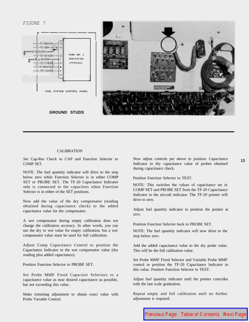
FIGURE 7
r
11
I
J
E
BI F
C
T A N K N O . 1
I N D I C A T O R
( T Y P I C A L )
F U E L S Y S T E M C O N T R O L P A N E L
GROUND STUDS
CALIBRATION
Set Cap-Res Check to CAP and Function Selector toCOMP SET.
NOTE: The fuel quantity indicator will drive to the stopbelow zero while Function Selector is in either COMPSET or PROBE SET. The TF-20 Capacitance Indicatoronly is connected to the capacitors when FunctionSelector is in either of the SET positions.
Now add the value of the dry compensator (readingobtained during capacitance check) to the addedcapacitance value for the compensator.
A wet compensator during empty calibration does notchange the calibration accuracy. In other words, you canuse the dry or wet value for empty calibration; but a wetcompensator value must be used for full calibration.
Adjust Comp Capacitance Control to position theCapacitance Indicator to the wet compensator value (dryreading plus added capacitance).
Position Function Selector to PROBE SET.
Set Probe MMF Fixed Capacitor Selectors to acapacitance value as near desired capacitance as possible,but not exceeding this value.
Make trimming adjustment to obtain exact value with Repeat empty and full calibration until no furtherProbe Variable Control. adjustment is required.
Now adjust controls per above to position CapacitanceIndicator to dry capacitance value of probes obtainedduring capacitance check.
13
Position Function Selector to TEST.
NOTE: This switches the values of capacitance set inCOMP SET and PROBE SET from the TF-20 CapacitanceIndicator to the aircraft indicator. The TF-20 pointer willdrive to zero.
Adjust fuel quantity indicator to position the pointer atzero.
Position Function Selector back to PROBE SET.
NOTE: The fuel quantity indicator will now drive to thestop below zero.
Add the added capacitance value to the dry probe value.This will be the full calibration value.
Set Probe MMF Fixed Selector and Variable Probe MMFcontrol to position the TF-20 Capacitance Indicator tothis value. Position Function Selector to TEST.
Adjust fuel quantity indicator until the pointer coincideswith the last scale graduation.

NOTE: Remember, when the TF-20 CapacitanceIndicator is reading capacitance, the aircraft fuel quantityindicator capacitance leads are open.
INDEPENDENT USE. . . Each section of the TF-20 canbe used independently of the other section. If MD-2Acapability only is required, connect the coaxial cable tothe TANK UNIT section COAX connector, andunshielded lead to either COMP or UNSH connector.Function Selector must be positioned to coincide withconnections (TANK UNIT TEST-COMP or PROBE).
If MD-1 capability only is required, use the TEST INDconnections.
TO CHECK A PROBE FOR CONTAMINATION.. After completion of the dry capacitance check of theindividual tank unit or tank unit and compensator, asd e t a i l e d i n T.O.'s 5L14-3-21-13 and 5L14-3-21-43,immerse the end of the tank unit or tank unit andcompensator in approximately six inches of clear tapwater (with the probe still connected to MD-2A orTF-20). The capacitance will increase and the bridge(MD-2A or TF-20) will not balance if the probe is allowedto remain in the water.
14
Remove the probe from the water and thoroughly shakeoff the residual water.
Continue to monitor capacitance with an MD-2A orTF-20. If the unit is not contaminated, the capacitanceshould, within 20 seconds after removal of the residualwater, return to within +2 MMF of the value noted during the dry capacitance check before water immersion. Thelength of time required for the probe to return to itsnormal capacitance is proportional to, and an indicationof, the extent of contamination.
Failure to pass this test is not justification to discard theprobe. It does indicate, however, that the probe should bewashed, as described later under the quick referencetroubleshooting tips.
Repeat these tests. If the probe passes, it should be readyfor further service.
For Quick Reference, here are a few Hercules fuelquantity indicating system troubleshooting tips....
A positive error in the compensator causes a negative errorin the indicatorreading.
A negative error in the compensator causes a positive errorin the indicator reading.
An open shield always causes high capacitance readingsfor both the compensator and the tank units (probes).
A water-contaminated probe and compensator caneither apositive or negative error in the indicator.
Contaminated probes can generally be restored bycarefully washing in water and a mild detergent, thorouglyrinsing in clear warm water, and baking dry. Dryingtemperature should be approximately 150°F, a smentioned above, and shop air must not be used to blowmoisture out of probes, since it can recontaminate theprobe with oil mist and dirty water.
Intermittent malfunctions that will not repeat on theground can usually be located by monitoring thecapacitance of the tank units with the MD-2A or TF-20,while lightly pulling and flexing the wiring and connectorsin the tank. Any change in the capacitance reading iscause to disassemble and inspect a suspect connector.Capacitance decrease indicates an open coaxial cablecenter conductor, an open unshielded lead, or the coaxialcable center conductor shorted to its shield. Capacitanceincrease indicates open coaxial shield.
Excessive moisture in the coaxialcause the indicator to read in error.
cable connectors can
If you calibrate an indicator by the preferred method(added capacitance to a dry tank) with the compensatorpartially immersed in fuel, the indicator will have apositive error. EXPLANATION: Added capacitance plusdry compensator equals a wet compensator. Addedcapacitance plus a partially wet compensator equalsabnormally high compensator capacitance. When MD-l isremoved and aircraft wiring reconnected, the compensatorcapacitance presented to the indicator is now lower invalue, and the indicator will move upscale in error, exceptat empty. Monitor the compensator capacitance with theMD-2A or TF-20 just prior to calibration to determinethat residual fuel has not drained back on thecompensator.
Sluggish, slow moving indicators can be caused bycontaminated probes and compensators (low resistancepaths between the electrodes), moisture in connectors,and shorts in system wiring.
You can check the coaxial cable from the cockpit to thetank boundary for stray capacitance by simplydisconnecting the connector(s) at the tank boundary andreading capacitance on the MD-2A or TF-20 in thecockpit. Capacitance should be nearly zero.
Intermittent faults in test cables can cause you to drawconclusions that are misleading, resulting intime-consuming unnecessary replacement of serviceablecomponents.

TWO DIFFERENT HERCULES ENGINEDRIVEN HYDRAULIC PUMPS
Two manufacturers are now supplying enginedriven hydraulic pumps for our Hercules air-planes. Most of the commercial and foreignmilitary configurations are equipped with pumpsmanufactured by Vickers Aerospace Division,Sperry Rand Corporation. U.S. Military config-urations have the pump manufactured by NewYork Air Brake Company installed as originalequipment. For resupply purposes the U.S.Military has procured some Vickers pumps andwe understand these are being installed onC-130A models only.
The StarTips item on “How to Bleed a HerculesHydraulic Pump - and Keep it Clean” in ourApril - June 1974 issue Service News appliesonly to the New York Air Brake pumpinstallation. Fluid under pressure from thesuction boost pump can pass through the NYABpump by opening the check valves at the ends ofthe cylinders, although this engine driven pump isnot rotating. This installation includes a “runaround” loop of tubing (C-130B model and up)to cool and recirculate fluid to prevent the pumpfrom overheating when the pump is in “isola-t ion”; i .e. , pump switched off with engineturning. Part numbers for these NYAB pumps are66WBD300, 66WBD300-1, 66WBD300-4 a n d66W U300-2.
The newer Vickers pump, part numberPV3-075-4, does not require the external loop forcooling. Also, the Vickers pump must rotate forfluid to flow through it. In both installations,rotation of the engine rotates the pump.
The suction boost pumps located near thereservoirs are used to provide a positive hydraulicpressure of 70-l 10 PSI to the suction side of eachengine driven pump when turned on. Thispressure prevents cavitation and helps to “prime”an engine driven pump should air get into thesuction line. If the reservoir fluid level is keptwithin limits and correct maintenance proceduresare followed, air will not enter the system.
When a hydraulic component is replaced, thecavities of the new unit should be filled withsystem fluid (MI L-H-5606) just before installationto minimize entrapment of air. This is especiallytrue when replacing engine driven pumps, Alwaysfill the pump case to overflowing through the casedrain port. Also, retain as much fluid as possiblein d isconnected tub ing dur ing componentchanges. Become familiar with all the instruc-tions in your maintenance manuals to avoid extraexpense - and work.
The compensator is the greatest offender with respect towater contamination.
Hercules Fuel Quantity Indicator Linearity
Major DialCalibrationIn Pounds
01000200030004000500060007000800090009400
0100020003000400050006000700080008800
01000200030004000500060006600
01000200030004000500060007000800090009800
Except C-130A & D Series
(Fuel Weight to Capacitance)
Outboard Tank Indicators
2.57mmf/100 Ibs
CapacitanceIn mmf *
213.5239.2 +/-5264.9 +/- 5290.6 +/- 5316.3+/- 5342.0 +/- 5367.7 +/- 5393.4 +/- 5419.1 +/- 5444.8 +/- 5455.1
Inboard Tank Indicators3.31 mmf/100 Ibs
256.4289.5 +/- 7322.6 7355.7 +/- 7388.8 +/- 7421.8 +/-7454.9 +/-7488.0+/- 7521.1 +/-7547.6
Auxiliary Tank Indicators2.85mmf/100 Ibs
169.8198.3 +/- 6226.8 +/- 6255.3 +/- 6283.7 +/- 6312.2+/-6340.1 +/- 6357.8
Pylon (External) Tank Indicators3.99mmf/100 Ibs
330.7370.6 +/- 8410.5+/-8450.5 +/- 8490.4 +/- 8530.3 +/- 8570.2 +/- 8610.1 +/- 8650.0+/- 8690.0 +/- 8721.9
* Increase value shown by 5% for tanks with foam installed.
Use this table to check the validity of any calibration you suspectmay have been made using a dipstick. Chances are you willdecide to recalibrate using the preferred or alternate method.
15

b y ELBERT FIELDS, Service Analyst
Correct assembly of the Cinch NuLine fuel quantityindicating system connectors is very important. Assemblyinstructions for coaxial (shielded) cable connectors (NuLinePart Numbers 12 1 l-404 and 122 l-404) are shown in Figure 2and instructions for unshielded lead connectors (NuLine PartNumbers 1231-106, 1231-206, 1244-106, 1244-206,1246-106 and 1246-206) are shown in Figure 3. It isimportant to torque correctly the hex back-end nut to insurethat the V-gasket is cut, providing metal-to-metal locking ofthe shielding to the shell , maximum environmentalprotection (moisture sealing), and effective locking of theback-end nut. The .042 inch maximum gap between the nutand body assembly is a good indication the nut has beenproperly torqued.
If for any reason a connector is disassembled, a new V-gasket(also called a chevron washer) must be installed. (SeeFigure 1 for part number.) All pieces of the old V-gasketmust be removed. If the braid clamp collar is missing, check
16 inside the shell. Be sure the braid is not broken and issmoothly combed in place before reassembly. Also, make
sure the groove in the V-gasket is pointing forward and theinternal taper of the braid clamp collar conforms to thebrushed-back braid on the braid clamp. Assembly of theconnector with the internal taper of the braid clamp collarbackwards will shear the shield braid, resulting in anintermittent connection.
On the rear wing beam, at the outer wing break and at thepylon tank disconnect, three new connectors replace oneearlier multipin connector, bringing each lead through aseparate connector. A new adapter fits the existing multipinconnector hole, and new holes are drilled for the remainingconnectors.
Information regarding fuel quantity wire and cable used withthe new connectors is detailed in an article, “Hercules WireIdentification”, Page 9 of the April - June 1974 issue ofService News.
Here is a table listing the NuLine connectors:
FIGURE 1 F U E L QUANTITY INDICATING SYSTEM CONNECTORS USED ON C-l 30 HERCULES AIRCRAFT
Item No. NuLineP/N
Federal Stock No. Description Type Contact V-GasketP/N*
Front GasketP/N*
ReplacesP/N*
P-870 1211-404 5935-071-7329
J-502 122 I-404 5935-071-7330
P-67 1 1231-106 5935-909.2358
P.872 1231-206 5935-946-Q 1 94
J-514 1244-l 06 5935-071-7331
J-512 1244-206 5935-07 1-7332
J-517 1246-l 06 5935-07 I-7333
J-516 1246-206 5936-947-9275
J-513 1284-451 NSL
Shielded Cable Pin B 138009 A 138007 5329-1
PlugShielded Cable Socket B 138009 None 5166-I
JackUnshielded Cable Socket B 138014 A 138006 1-906-l
PlugUnshielded Cable Pin B 138014 A 138007 1-728-1PlugGlass Seal Bulkhead Pin B 138014 NoneFeed Thru Unshielded
CombinationsCable Jack
of theseGlass Seal Bulkhead Socket B 138014 NoneFeed Thru UnshieldedCable Jack
connectorsreplace VendorP/N’s
Bulkhead Feed Thru Pin B 138014 NoneUnshielded Cable Jack
I
165-67,
Bulkhead Feed Thru Socket B 138014 None165-67W, and165-67XUnshielded Cable Jack
Isolated Ground Socket None NoneBulkhead Feed ThruAdapter
*Federal Stock Numbers have not been assigned to the gaskets.

C O N N E C T O R S
FIGURE 2
S T E P 1 .
S L I D E T H E H E X N U T , F L A T W A S H E R A N D V - G A S K E T O V E R T H E
J A C K E T . S C R E W T H E T H R E A D E D B R A I D C L A M P O V E R T H E J A C K E T ,
N O T E : T A K E C A R E N O T T O D A M A G E K N I F E E D G E O F B R A I D C L A M P .
S T R I P T H E J A C K E T U N T I L 1/2 I N C H O F B R A I D I S E X P O S E D . S C R E W T H E
B R A I D C L A M P B A C K U N T I L I T I S F L U S H W I T H E D G E O F J A C K E T .
FLAT WASHER /BRAID
V-GASKET
STEP 2
U S E A T H I N P R O D T O U N B R A I D A N D S T R A I G H T E N T H E B R A I D
S T R A N D S .
RADIUS EDGE
HEX NUT V-GASKET KNIFE EDGE
STEP 3.
U S E A N Y L O N B R U S H T O C O M B T H E B R A I D B A C K O V E R T H E R A D I U S
E D G E O F T H E B R A I D C L A M P . A N I D E A L B R U S H F O R T H I S P U R P O S E
C A N B E M A D E B Y T R I M M I N G T H E B R I S T L E S O F A H A R D N Y L O N
T O O T H B R U S H . T H E S T R A N D S S H O U L D L I E A P P R O X I M A T E L Y P A R .
A L L E L T O E A C H O T H E R .
FLAT WASHERBRAID CL A M P
BRAID
HEX NUT ‘V-GASKET
S T E P 4
P R E S S O N T H E B R A I D C L A M P C O L L A R H A L F W A Y O N T O B R A I D C L A M P
W I T H L A R G E S T I N S I D E D I A . O F B R A I D C L A M P C O L L A R A W A Y F R O M
C O N T A C T . N O T E I T I S M O S T I M P O R T A N T A T T H I S S T E P T O A S S E M B L E
B R A I D C L A M P C O R R E C T L Y T O P R E V E N T S H E A R I N G O F B R A I D
S T R A N D S . T R I M T H E B R A I D W I T H T H E R A Z O R B L A D E O R S H A R P K N I F E
T O + . O O O - 0 2 5 W I T H I N S H O U L D E R O F B R A I D C L A M P . D O N O T U S E
“ D Y K E S ” F O R T R I M M I N G . N O C R I M P I N G O R S Q U E E Z I N G T O O L S A R E
T O B E U S E D T O I N S T A L L O R S E A T B R A I D C L A M P C O L L A R . T H I S I S T O
P R E V E N T D A M A G E T O K N I F E E D G E O F B R A I D C L A M P ,
FLAT WASHER KNIFE EDGE
, _ B R A l D
BRAID CLAMP COLLARNOTE INTERNAL TAPER
HEX NUT I BRAID CLAMPV-GASKET
S T E P 5
A D D T H E 0 - R I N G A N D C O N T A C T R E T A I N E R . C U T O F F T H E P R I M A R Y
I N S U L A T I O N F L U S H W I T H T H E K E L - F C O N T A C T R E T A I N E R . C U T T H E
C E N T E R C O N D U C T O R A P P R O X I M A T E L Y 0 8 I N C H B E Y O N D T H E
I N S U L A T I O N . T I N T H E C E N T E R C O N D U C T O R W I T H Q Q - W - 5 7 1 C C O M P
S N 5 0 O R 6 0 S O L D E R . S U P E R I O R N O .30 F L U X M A Y B E U S E D D U R I N G
T I N N I N G O F W I R E .
* O - R I N G
17S T E P 6.
P R E S O L D E R C O N T A C T , P L A C E T H E C O N T A C T O N T H E W I R E A N D A P P L Y
H E A T U N T I L S O L D E R F L O W S . O B S E R V E T H E F L O W O F S O L D E R
T H R O U G H T H E I N S P E C T I O N H O L E . T H E P R O P E R T E M P E R A T U R E E X I S T S
W H E N S O L D E R A P P E A R S I N T H E H O L E . C A R E F U L L Y R E M O V E A N Y
E X C E S S S O L D E R O N O U T E R S U R F A C E O F C O N T A C T .
NO GAP
INSPECTION HOLE
TRIM AS NECESSARY
STEP 7.
P L A C E C O N T A C T I N S U L A T O R O N C O N T A C T . A P P L Y A P P R O X . 1 D R O P
O F MIL-S-22473C G R A D E A O R A A S E A L A N T T O H E X N U T T H R E A D S .
I N S E R T C A B L E A S S E M B L Y I N T O S H E L L A N D T O R Q U E D O W N T O 8 T O 1 0
IN -LBS U S I N G C A L I B R A T E D O R D I A L T Y P E T O R Q U E W R E N C H . T H E
8 T O 1 0 I N - L B S A P P L I E D W I L L S E A T T H E B R A I D C L A M P S H O U L D E R
A N D C U T T H R O U G H T H E V - G A S K E T * O N P L U G S , P L A C E M O I S T U R E S E A L
I N C O N N E C T O R S H E L L C H E C K T H E C O N T A C T O N P L U G S T O A , 1 2 5
M A X I M U M D I M E N S I O N A N D O N J A C K S O R R E C E P T A C L E S T O A , 0 5 0
M A X I M U M D I M E N S I O N .
SHELL (1211-404 PLUG ILLUSTRATED-OUTLINE OF OTHER COAX TYPECONNECTORS MAY VARY1
.050 MAX. (JACKS OR RECEPTACLES]
,125 MAX. (PLUGS)
CONTACT (PINILLUSTRATED)
T INSUL
SEALONLY)
TYPE
ATOR
* W h e n properly torqued, gap be tween nu t and body assemb ly shou ld no t exceed

FIGURE 3
STEP 1.
SLlDE H E X N U T , F L A T W A S H E R , � - G A S K E T , A N D C A B L E C L A M P
RETAlNER O V E R J A C K E T A S S H O W N . S T R I P J A C K E T O F F C E N T E R
CONDUCTOR TO EXPOSE 0.080 INCH OF CONDUCTOR.
STEP 2.
SCREW CABLE CLAMP IN PLACE ON JACKET AS SHOWN PROVIDING
SPACE ON JACKET FOR 0 -RING. N O T E C A B L E C L A M P R E T A I N E R � S
POSlTlON M A Y V A RY BUT WlLL TlGHTEN D O W N W H E N T H E A S S Y I S
INSERTED INTO SHELL, PLACE O-RING AS S H O W N .
STEP 3
T I N T H E C E N T E R C O N D U C T O R W I T H 00-W-571C COMP SN50 OR 60
SOLDER. PRESOLQER CONTACT, PLACE THE CONTACT ON THE WIRE
AND APPLY HEAT U N T I L S O L D E R F L O W S . O B S E R V E T H E F L O W O F
18 S O L D E R THROUGH THE INSPECTION H O L E . T H E P R O P E R T E M P E R A .
TURE E X I S T S W H E N S O L D E R A P P E A RS IN T H E H O L E . C A R E F U L L Y
REMOVE ANY EXCESS SOLDER ON OUTER SURFACE OF CONTACT.
STEP 4
PLACE CONTACT INSULATOR ON CONTACT, APPLY APPROX. 1 DROP
OF MIL-S-22473C GRADE A OR AA SEALANT TO HEX NUT THREADS.
INSERT CABLE ASSEMBLY INTO SHELL AND TORQUE DOWN TO 8T0 10
INCH-LBS. USlNG CALIBRATED OR DIAL TYPE TORQUE WRENCH* ON
PLUGS, PLACE MOISTURE SEAL IN CONNECTOR SHELL. CHECK THE
CONTACT ON PLUGS TO A ,125 MAXIMUM DIMENSION AND ON JACKS
OR RECEPTACLES TO A ,050 MAXIMUM DIMENSION. 00 NOT CHECK
CONTACT DlMENSlONS ON GLASS SEAL BULKHEAD FEED THRU JACKS
(1244 SERIES) SlNCE THE EXTERNAL CONTACT IS POSITIONED D U R I N G
MANUFACTURE OF SHELL.
Delayed Maintenance
by TED FABER, Aerospace Safety Engineer, Senior
The companion article entitled, “Troubleshooting theHercules Fuel Quantity Indicating System” points outthat troubleshooting the fuel quantity indicating systemrequires strict adherence to all safety precautions whenchecking the system. This is also true when repairs arerequired and is especially important when repair involvesthe Amphenol 16.5 series fuel quantity indicator harnessconnector plugs.
The fuel quantity indicating system is designed as anelectrically inert capacitance system, specifically designedto eliminate any possibility of arcing from electricallycharged components within the system. However, whencareful attention is not observed during repair orreinstallation of these connectors, it is possible to route11.5 volts to the fuel tank through the shielded coaxialcable. This can be accomplished through misalignment ofthe connector pins or otherwise causing the wire shieldingto contact the 1 15-volt AC pin. On one occasion, anexplosion occurred when electrical power was restoredafter maintenance had been performed on the NumberFour tank fuel quantity system. Investigation revealedthat an instrument specialist was troubleshooting theindicating system as a result of a fuel quantity write up.External power was disconnected and then reconnectedafter the MD-2A fuel tester was used. The specialist wasin the process of visually checking the fuel quantity gagewiring, with the gage removed from the overhead panelmounting socket, and with the plug connected, when theexplosion occurred. The explosion ruptured the fuel tankand caused extensive structural wing damage.
In this mishap it was found that during assembly of theAmphenol connector, the retainer ring was not used. Theabsence of the retainer ring allowed the plug socket tomove outward from the plug shell, disengaging the socketkeyway and permitting the socket to rotate approxi-mately 120 degrees before mating. This allowed pin “J”

..Can Give You A
in the connector to contact receptacle “B” in the socket,allowing 115 volts to pass from pin “J”, which is commonground, to the coaxial cable shield. When 1 15 volts wasapplied to the system, a ground, through a fault in theouter covering of the coaxial cable, was obtained, andarced to aircraft structure, igniting fuel fumes in the tank.
In a similar manner an explosion occurred in the NumberOne tank of a Hercules as the aircraft was climbing toaltitude for an extended over water mission, Theexplosion resulted in an extensive wing fire and the crewwas forced to land the aircraft in a nearby corn field withthe landing gear retracted. After landing, the crewevacuated the aircraft safely and the local FireDepartment extinguished the fir-e.
In this accident, delayed maintenance to correct repeatedwrite ups against the Number One tank fuel quantityindication played a vital role. Over a period of twomonths the indicator was reported for reading “off scale”a number of times. Each time the discrepancy wascorrected by resoldering the plug connections but thecorrective action taken did not eliminate the problem.The last time, maintenance action to correct themalfunction was interrupted by an operational com-mitment to use the aircraft. The plug was hastilyreassembled and connected to the indicator. The fuelquantity circuit breaker was pulled and the flight engineerwas verbally advised to keep the circuit breaker pulled.This advice was passed on from one flight engineer toanother for a time but this communications system finallybroke down and the circuit breaker was pushed in prior tothe last flight. When this occurred 11 5-volt current wasdirected to the Number One fuel tank. When sufficientfuel had been consumed from the tank to create anexplosive atmosphere,arcing between a fault in thecoaxial cable and internal wing structure resulted in thesubsequent explosion. Later examination of the con-nector plug revealed the 11 5-volt wire was in contact withthe coaxial shield and the shield was not grounded to thecase.
Both mishaps could have been avoided by carefullyfollowing procedures contained in service manuals andhaving a better understanding of the fuel quantityindicating system. Failure of the indicator to self test orfailure of the indicator to display proper fuel quantityshould have alerted the flight crew and maintenancepersonnel to the possibility of a faulty connector plug.
LOCKHEED RECOMMENDS the following safety pre-cautions be adhered to during operation of the fuelquantity indicating system:
Failure of the indicator to test is indicative of amalfunction in the fuel quantity indicating system.Maintenance action should be taken. If maintenanceis not complete, pull and pin the circuit breaker forthat indicator. Failure to comply may result in highvoltage being routed to the fuel tank which couldcause an explosion.
Fuel quantity indicators should not be removed orchanged in flight. If a fuel quantity indicatormalfunctions or fails the press to test check, pull therespective circuit breaker and leave it out. If a fuelquantity indicator circuit breaker pops, do notattempt to reset it. Failure to comply may result inhigh voltage being routed to the fuel tank whichcould cause an explosion.
After landing write up the discrepancy and havemaintenance correct the problem, NOW! Tomorrow maybe too late!

How
by J. S. RENO, Service Engineer, Hamilton Standard
20SOURCE OF COOLING for the JetStar air conditioningsystem is the refrigeration package designed andmanufactured by Hamilton Standard, a division of UnitedAircraft Corporation.
Two refrigeration packages, employed in parallel, converthigh temperature, high pressure engine bleed air toconditions providing a comfortable environment in theJetStar’s cabin and flight deck.
Each refrigeration package is a two-stage cooling deviceconsisting of a heat exchanger and a turbine-fan unit,sometimes referred to as an air cycle machine. The heatexchanger provides initial cooling by transferring heatfrom the bleed air to ambient ram air which passesthrough the heat exchanger and is then dumpedoverboard. The second stage of cooling is accomplishedwith the turbine-fan. Cooling is obtained as the airexpands through the turbine where heat is converted intomechanical energy. This energy is dissipated through thefan as it helps to move the ram air through the heatexchanger. Acting primarily as a load for the turbine, thefan serves a dual purpose in that it also induces air flowthrough the ambient side of the heat exchanger when theaircraft is moving too slowly to generate ram flow.
The shaft on which the turbine and fan are mounted issupported by two ball bearings, spaced on one end of theshaft and contained within the bearing cartridge. Thecartridge extends into the cold air of the turbine
discharge, providing ideal bearing operating temperatures.The bearings are lubricated by means of capillary wickswhich draw oil from a small reservoir. The wicks wipe theoil onto tapered sections of the shaft which, throughcentrifugal action, sling the oil as a fine mist into thebearings.
Here are inspection, maintenance, and overhaul recom-mendations for the JetStar refrigeration unit.
INSPECTION OF OIL SUMP
At the end of each 500 hours of flying time, theturbine-fan oil sump should be inspected for oil level. (Seeeditor’s notes following article.) Look at the translucentplastic oil sump while it is installed on the package. Don’tadd oil if its addition would result in its overflowing thesump’s spouts; any level less than full will require additionof MILL-6085A oil.
If oil is added, the filler plug preformed packing, P/NMS28778-2 should be replaced.
The sump should also be inspected for the accumulationof water (considered normal when high humidity ambientconditions prevail). Any water present should be removedwith a suction syringe. Since atmospheric and operatingconditions determine the rate of water accumulation, theperiod for sump inspection for the presence of water mustbe established by each operator.


REPLACEMENT OF THE TURBINE-FAN ASSEMBLY
Replacement of the turbine-fan assembly may beaccomplished as follows:
1.
2.
3.
4.
5.
Remove the oil through the filler port of the sump ofthe turbine-fan with a suction-type syringe.
Remove the two bolts and washers at the turbineinlet/bleed air duct junction.
Decouple the Marmon clamp between the turbine-fanand the heat exchanger and remove the turbine-fan.
When installing the new turbine-fan, replace the twopreformed packings, P/N 69490B218 at the turbineinlet/bleed air duct and P/N 69490B247 betweenturbine-fan and heat exchanger. Attach the Marmonclamp loosely, line up the bleed air duct to turbineinlet, install the two bolts, secure the Marmon clampand lockwire as required.
Service the oil sump with MIL-L-6085A oil after thepackage is installed in the aircraft.
REPLACEMENT ON OVERHAUL INTERVAL
The turbine-fan should be overhauled each 1500 hours offlying time. (See editor’s notes following article.) Theheat exchanger may continue in service.
CAUTIONARY CONSIDERATION
Handling of the package with oil in the sump should beheld to a minimum, and only with the sump in downposition. It is preferred that the sump be serviced afterthe package is installed in the aircraft, and the oil beremoved with a syringe prior to removal of the packagefrom the aircraft. The package should never be shippedwith oil in the sump.
Should the package be inverted with oil in the sump, theoil could be introduced into the air passageways, whichwill result in smoke or fumes in the conditioned air. Thiswould require removal of the turbine-fan assembly andreturn to an overhaul facility for thorough cleaning.
When installing a turbine-fan assembly or refrigerationpackage in the aircraft, make sure that the oil sump is
22
Cutaway of
JetStar Turbine-Fan
Assembly
TURBINE WHEEL
BEARING SLEEVE NUT
(NOT TO BE R E M O V E D

filled for at least three hours prior to running the pack-age. The lubrication wicks must be saturated with oil forthis minimum time period before they will provideadequate lubrication to the bearings.
Hamilton Standard provides a turbine-fan exchangeservice for the repair and overhaul needs of all JetStaroperators. Participation in this Exchange Program enablesan operator to obtain a zero time turbine-fan in advanceof removal of a unit in need of repair or overhaul. Thisability to secure replacement turbine-fans in anticipationof scheduled removals minimizes maintenance down time.
Reprint From AirLifters Vol. 1, No. 4
EDITOR’S NOTES
The JetStar Handbook of Operating and MaintenanceInstructions (HOMI) published by Lockheed specifies thatthe lubricating oil be changed every 500 hours. Any oilavailable that conforms to MIL-L-6085A can be used.This precautionary maintenance against contaminationcontributes to more hours between overhaul. Otherfactors have helped to increase the TBO to 5,000 hours asspecified in the JetStar Operator’s Maintenance Report.However, the manufacturer recommends a TBO of 1,500hours or 21/2 years, whichever occurs first.
We wish to elaborate on the approach to the problem of a“frozen” turbine wheel. Lockheed has also heard fieldreports that indicate attempts were made to unstickturbine rotors by pushing o n the fan blades. Damage tothese elements, although not apparent, can be destructiveat operating speeds near 60,000 RPM. If the rotor stickson a high time refrigeration turbine, the unit should bereplaced.
On rare occasions, it has happened that, during the “wearin” period of earlier model refrigeration units, the rim ofthe turbine wheel stuck in the cadmium seal in the nozzleplate. Rubbing here may occur for as long as 500 hoursof operation before the wheel “seats in” to the seal. Ifattempts to start the refrigeration unit fail with theengines at full RPM, and there is reason to believe thatnon-rotation is due to seal drag, you can try a method ofapplying mechanical torque that has been approved.
The unit must be removed from the airplane, the turbine-fan separated from the heat exchanger, and torque up to100 inch-pounds applied to the fan nut in the direction ofnormal rotation. The oil level in the reservoir should beadequate during any run attempts; and, remember to keepthe reservoir positioned down at all times when the unit isremoved, as pointed out in your Maintenance Manual.
After freeing the rotor, a bench run can be made withbleed air, if available, or with a drill motor and a flexiblecoupling such as a hose clamped to the fan nut.
While the earlier configuration turbine fans, P/N 584395,were susceptible to turbine wheel/cadmium seal binding,the later configuration turbine fans, P/N 726638-1,contain an improved seal arrangement which is not sus-ceptible to binding. Thus, if a later configuration unitdoes not rotate while being subjected to full engine bleedpressures, it should be removed from service and returnedto an overhaul facility for investigation.
23
HOW THE 1867TH FCS LICKED A TURBINEPROBLEM
by E. P. CARY, JR., Field Service Representative
THE 1867th FACILITY CHECKING SQUAD-RON at Clark Air Base in the Philippines fliesJetStars l ow and s low i n ho t and humidenvironments.
Sustained low altitude flight causes heavy watercondensation in the cooling turbine oil reservoir,ultimately causing turbine bearing failure.
These hard-flying pilots have to fly low and slowto perform their mission, checking navigationalfacilities in Southeast Asia - such as PrecisionApproach Radar and Tacan - to make sure theyare functioning properly for the safety of otheraircrews.
To lick this special problem, the 1867th FCSinstituted a special maintenance procedure -removing and replacing reservoir oil every 25flight hours. As a result, turbine bearing life wasmaterially improved.
Reprint From AirLifters Vol. 1, NO. 4

CUSTOMER SERVICE DIVISION ~OCKHEED-GEORGIA COMPANY A 01¥ llt0H Of 1,.0CttH£€0 Alf'C.fl AFT CQl'lf'OllA1 t0 ... 1ii1.A•1•TTA Cl O"C1.-._ )ICI063