
Vol-III of IV - Laying - Hpcl
527
Hindustan Petroleum Corporation Limited (A Govt. of India Undertaking) Mumbai (India) BID DOCUMENT FOR CONSTRUCTION OF 10" DIA. X 15 KM (APPROX.) & 8” DIA X 15 KM (APPROX.) STEEL PIPELINE, TERMINALS AND ASSOCIATED FACILITIES FOR BAHADURGARH TIKRIKALAN PIPELINE OPEN DOMESTIC COMPETITIVE BIDDING BASIS E-Tender No. : 7280 TENDER NO.: 05/51/23LK/HPCL/001(i) VOLUME - III OF IV MECON LIMITED SCOPE MINAR 13 th & 15 th Floor, North Tower Laxmi Nagar District Centre DELHI – 110 092 DEC., 2009
Transcript of Vol-III of IV - Laying - Hpcl

Hindustan Petroleum Corporation Limited (A Govt. of India Undertaking)
Mumbai (India)
BID DOCUMENT
FOR
CONSTRUCTION OF 10" DIA. X 15 KM (APPROX.) & 8”DIA X 15 KM (APPROX.) STEEL PIPELINE, TERMINALS AND ASSOCIATED FACILITIES FOR BAHADURGARH
TIKRIKALAN PIPELINE
OPEN DOMESTIC COMPETITIVE BIDDING BASIS
E-Tender No. : 7280TENDER NO.: 05/51/23LK/HPCL/001(i)
VOLUME - III OF IV
MECON LIMITEDSCOPE MINAR
13th & 15th Floor, North TowerLaxmi Nagar District Centre
DELHI – 110 092DEC., 2009

Hindustan Petroleum Corporation Ltd.
CONSTRUCTION OF 10" DIA. X 15 KM (APPROX.) & 8” DIA X 15 KM (APPROX.) STEEL PIPELINE,
TERMINALS AND ASSOCIATED FACILITIES FOR BAHADURGARH TIKRIKALAN PIPELINE
Bid Doc. No.: 05/51/23LK/HPCL/001(i)
MECON LIMITED
D:\old data\Vijyant\HPCL\Tender\Laying\Vol-III of IV\Contents Vol III of IV-BTPL.doc Page 1 of 1
C O N T E N T S
LIST OF SPECIFICATION / STANDARDS VOLUME-III OF IV
1. Technical Specification for Civil & Architectural Works
2. Technical Specification for Structural Works
3. Specification for Installation of Instruments MEC/S/05/26/01
4. Specification for Instrument Tubing MEC/S/05/26/02
5. Specification for Inlet Outlet Sections & FS MEC/S/05/26/03
6. Specification for Instrument Tube Fittings MEC/S/05/26/04
7. Specification for Instrument Valves and Manifolds MEC/S/05/26/05
8. Specification for Junction Boxes and Cable Glands MEC/S/05/26/06
9. Specification for Signal Cable MEC/S/05/26/07
10. General Technical Specification for Instrumentation MEC/S/05/26/08
11. Specification for Cabling MEC/S/05/26/21
12. Specification for Earthing MEC/S/05/26/23A
13. Specification for Optical Fiber Cable & HDPE Duct Laying and Associated Work
MEC/S/05/E5/T/001
14. Specification / Procedure for Optical Fiber Cable Testing MEC/S/05/E5/T/002
15. Technical Specification for Optical Fiber Cable & Accessories MEC/TS/05/E5/T/096
16. Technical Specification PLE HDPE Telecom Duct and Accessories
MEC/TS/05/E5/T/037
17. Technical Specification of Warning Mats for OFC & Telecommunication HDPE Duct
MEC/TS/05/E5/T/042

CHAPTER : CIVIL & ARCHITECTURAL 1 OF 292
TECHNICAL SPECIFICATION FOR CIVIL & ARCHITECTURAL WORKS
INDEX
PART - I MATERIALS
PART - II WORKMANSHIP
PART - III NORMS OF CEMENT CONSUMPTION
PART - IV DIMENSIONAL TOLERANCE
PART - V METHOD OF MEASUREMENT
PART - VI SAFETY REQUIREMENTS FOR CONSTRUCTION WORK
ANNEXURE-A LIST OF IS & CODES REFERRED
ANNEXURE-B STANDAR DRAWINGS

CHAPTER : CIVIL & ARCHITECTURAL 2 OF 292
SPECIFICATION FOR CIVIL & ARCHITECTURAL WORKS:
PART I : MATERIALS 1.0 GENERAL 1.1 Scope This part deals with the requirements of materials for use in construction
work with regard to quality, testing, approval and storage, before they are used on work. This part is supplementary to Part-II: Workmanship and Other requirements of the Technical Specifications for civil works.
1.2 Standard A high standard of quality is required for all materials used in construction
work. They shall be the best of the kind obtainable indigenously in each case and shall be procured from manufacturers of repute in order to ensure uniformity of quality and assurance of timely supply.
1.3 Approval and Tests 1.3.1 All materials to be used in construction shall be subject to approval of the
Engineer. The Contractor shall apply sufficiently in advance with samples of the materials including the supporting test results from the approved laboratory and other documentary evidence from the manufacturer wherever applicable and indicating the types of materials and their respective sources. The delivery of materials at site shall commence only after the approval of the quality, grading and sources of the materials by the Engineer.
1.3.2 The quality of all materials once approved shall be maintained throughout
the period of construction and periodical tests shall be carried out to ensure that it is maintained. Such routine tests shall be listed under the different materials and/or as may be ordered by the Engineer from time to time.
1.3.3 Where a particular "Brand" or "Make" of material is specified in the Schedule of Items or Technical Specifications, such "Brand" or "Make" of material alone shall be used on the work. Should it become necessary for any reason (such as non-availability/ceased to be produced), to use any material other than the specified "Brand" or "Make", the Contractor shall submit sample of the same to the Engineer for approval together with test certificates and other documents necessary for examining and giving approval thereof. Should such change or substitution of materials, subsequently approved, results in use of material of price lower than that of the material specified in the Schedule of Items or Technical Specifications, the rates of work affected by the substitution shall be proportionately reduced. Similarly, in case the substitution results in use of material of price higher than that specified in the Schedule of Items or Technical Specifications, the rates of work affected by the substitution shall be proportionately increased.

CHAPTER : CIVIL & ARCHITECTURAL 3 OF 292
1.4 Codes 1.4.1 The years of publication against various standards, referred in this
specification, correspond to the latest standards as on date of preparation of this specification. During use of this specification in future, the latest publication as on date shall be referred to. Where standards are not yet published by the BIS or IRC, adoptable British Standards or other International Standards shall apply.
1.4.2 In case of any conflict in meaning between these specifications and those
of BIS or IRC, or British /International Standard; the provisions of these specifications shall prevail.
1.5 Rejection of Materials 1.5.1 Any material brought to site which, in the opinion of the Engineer is
damaged, contaminated, deteriorated or does not comply with the requirement of this specification shall be rejected.
1.5.2 If the routine tests or random site tests show that any of the materials,
brought to site, do not comply in any way with the requirements of this specification or of I.S. Codes as applicable, then that material shall be rejected.
1.5.3 The Contractor at his own cost shall remove from site any and all such
rejected material within the time specified by the Engineer. 2.0 MATERIALS FOR CONCRETE 2.1 Aggregates 2.1.1 Aggregates shall comply with the requirements of IS: 383-1970 "Coarse
and Fine Aggregates for Concrete". They shall be hard, strong, dense, durable, clean and free from veins and adherent coating, vegetable matter and other deleterious substances; and shall be obtained from approved sources. Aggregates shall not contain any harmful material such as pyrites, coal, lignite, shale or similar laminated material, clay, alkali, soft fragments, sea shells and organic impurities in such quantity as to affect the strength or durability of concrete. Aggregates which are chemically reactive with alkalies of cement shall not be used. Aggregates which are not sufficiently clean shall be washed in clean fresh water to the satisfaction of the Engineer.
2.1.2 Testing All aggregates shall be subject to inspection and testing. The Contractor
shall submit samples for testing as may be required by the Engineer. Sampling and testing shall be carried out in accordance with IS: 2386-1963 "Methods of Test for Aggregates for concrete".
2.1.3 Grading

CHAPTER : CIVIL & ARCHITECTURAL 4 OF 292
The Contractor shall ensure that the full range of aggregate used for
making concrete is graded in such a way as to ensure a dense workable mix. The delivery of aggregates will commence only when the Engineer has approved the samples and the quality and grade shall be maintained consistent and equal to the approved sample. Before construction commences, the Contractor shall carry out a series of tests on the aggregates and on the concrete made there from to determine the most suitable grading of the available aggregates. Once the most suitable grading has been found, the grading shall be adopted for the construction of the works and periodic tests shall be carried out to ensure that it is maintained.
2.1.3.1 Size and grading of fine aggregates The grading shall conform to IS: 383-1970 and shall be within the limits of
Grading Zone-III. The maximum size of particle shall be 4.75mm and shall be graded down. Sand containing more than 10% of fine grains passing through 150 micron sieve or having the fineness modulus less than 2 shall not be used for concrete work.
2.1.3.2 Size and grading of coarse aggregates
The nominal maximum size of the aggregates for each mark of concrete or for each type of work shall depend upon the description of the particular item in the Schedule of Items and/or according to relevant clauses of IS: 456-1978. The aggregates shall be well graded and the grading shall conform to relevant requirements of IS: 383-1970 depending upon the maximum nominal size as specified or as required.
2.1.3.3 Fine aggregate for mortar and grout
The grading of fine aggregate for mortar and grout shall be within the limits of grading zone III and IV as defined in IS: 383-1970.
2.1.4 Storage & stacking
Care shall be taken in the storage to avoid intrusion of any foreign materials into the aggregates and where two types of aggregates are stored close to each other, they shall be separated by a wall or plate. In case of stockpiling, care shall be taken to avoid forming pyramids resulting in segregation of different sized materials. The height of the stacks shall be generally limited to 150 cm.
2.2 Coarse Aggregates 2.2.1 Types
The type of coarse aggregate viz., stone chips, gravel or broken brick shall be as described in the Schedule of Items. Unless otherwise specified in the Schedule of Items, stone chips shall be used as coarse aggregate.
2.2.2 Stone chips

CHAPTER : CIVIL & ARCHITECTURAL 5 OF 292
It shall be crushed or broken from hard stone obtained from approved quarries of igneous or metamorphic origin. The stone chips shall be hard, strong, dense, durable and angular in shape. It shall be free from soft, friable, thin, flat, elongated or laminated and flaky pieces and free from dirt, clay lumps, and other deleterious materials like coal, lignites, silt, soft fragments, and other foreign materials which may affect adversely the strength & durability of concrete. The total amount of deleterious /foreign materials shall not exceed 5% by weight according to relevant clause of IS: 383-1970. If found necessary the stone chips shall be screened and washed before use.
2.2.3 Gravel
It can be either river bed shingle or pit gravel. It shall be sound, hard, clean, irregular in shape and suitably graded in size with or without some broken fragments. It shall be free from flat particles, powdered clay, silt, loam and other impurities. Before using, the gravel shall be screened and washed to the satisfaction of the Engineer. However, the foreign/deleterious materials shall not exceed 5% by weight.
2.2.4 Broken bricks / Brick aggregates
These shall be obtained by breaking well burnt or over burnt dense brick bats. They shall be homogeneous in texture, well graded in size, roughly cubical in shape, clean and free from dirt, clay, silt or any other deleterious matter. Before use, these shall be screened.
2.3 Fine Aggregates 2.3.1 Unless specified otherwise it shall either be natural river sand or pit sand. 2.3.2 Sand shall be clean, sharp, strong, angular and composed of hard siliceous
material. It shall not contain harmful organic impurities in such form or quantities as to affect adversely the strength and durability of concrete. Sand for reinforced concrete shall not contain any acidic or other impurities which is likely to attack steel reinforcement. The percentage of all deleterious materials including silt, clay etc., shall not exceed 5% by weight. If directed, sand shall be screened or washed before use to the satisfaction of Engineer.
2.3.3 Crusher dust
Crusher stone dust ( that is retained on 300 micron sieve ) may be used as replacement for certain quantum of sand aiming to improve the fineness modulus of fine aggregate. The quantum of replacement for sand shall be arrived at by suitable trial mixes. The Engineer will decide the final usage of crusher dust depending on the circumstances.
2.4 Lime
Lime for mortars and concrete shall conform to IS: 712-1984 The total of CaO and MgO content in quick lime shall not be less than 85% (MgO shall

CHAPTER : CIVIL & ARCHITECTURAL 6 OF 292
not exceed 5%). Quicklime, after slaking, shall leave a residue of not more than 5% by weight on IS sieve 85.
2.5 Surkhi
Surkhi used in lime concrete for flooring, terracing etc., shall conform to IS: 3182-1986. Surkhi shall be made from well burnt bricks or brickbats. Surkhi shall pass through I.S. sieve 3.35mm with at least 50 % of it passing through I.S. sieve 1.70mm and be perfectly clean and free from foreign matter. Surkhi shall not be made from bricks which have come in contact with any mortar.
2.6 Cement
Cement to be used in all types of RCC works shall be ordinary Portland cement Grade 43 conforming to IS: 8112-1989. The Contractor shall procure cement for all sections of Schedule ‘A’ required for this contract as the work proceeds at site.
2.6.1 Cement shall be procured by the contractor from the main producers of
cement enumerated as under: -
(i) ACC (Associated Cement Co. Ltd) (ii) Lafarge Cement (iii) Ambuja Cement (iv) Ultra Tech Cement (v) Birla Corp Ltd. (vi) Orient Cement. (vii) JK Cement. (viii) Madras Cement Ltd. (ix) Saurashtra Cement (x) Andhra Cements Ltd. (xi) Century Cement. (xii) Dalmia Cement (xiii) Binani Cement. (xiv) The India Cement (xv) Mangalam Cement. (xvi) Grasim Cement. (xvii) Shree Cement (xviii) Lakshmi cement (xix) Jaypee Rewa Cement
The particulars of the manufacturer / supplier of cement alongwith the date of manufacture shall be produced by the contractor for every lot of cement separately. The documents in support of the purchases of cement shall be produced before the Engineer-in-Charge for verification by the GE.
2.6.2 TESTING:- The contractor shall submit the manufacturer’s test certificate in original alongwith the Test Sheet giving the result of each physical test as applicable and the chemical composition of the cement or authenticated copy thereof, duly signed by the manufacturer with each consignment clearly bringing out lot
CHAPTER : CIVIL & ARCHITECTURAL 7 OF 292
No. The Engineer-in-Charge shall record these details in the cement acceptance register as given in Appx ‘G’ here-in-after after due verification. The GE shall also organize independent testing of random samples of cement (both physical and chemical properties) drawn from various lots for each consignment to cement brought out by the contractor before incorporation in the work from the National Test House, SEMT, Regional Research Laboratories, Government approved laboratories, as per IS: 3535-1986 (Method of sampling Hydraulic cement), IS: 4031 (Method of physical test for Hydraulic Cement) and IS: 4032-1985 (Method of chemical analysis of Hydraulic cement.)
2.6.3 Following mandatory tests shall be carried out for cement procured by the
Contractor: - (i) Initial and final setting time (ii) Soundness test
(iii) Compressive strength test at 3, 7 & 28 days as specified in relevant IS code.
2.6.4 The cement shall conform to chemical requirements and physical requirements as
specified in clause 4 & 5 respectively of IS: 269-1976. The tests carried out as per provisions of IS codes specified herein before shall be the criteria for acceptance of cement by Engr-in-Charge. If samples from a lot/lots are not within the acceptance limits of Indian standard the lot/lots shall be rejected without any claims or compensation to the contractor for the lot/lots purchased. The contractor shall replace the lot/lots with the fresh one, which shall be tested again for acceptance. The cost of all tests carried out on cement before acceptance for incorporation in the work shall be borne by the contractor whether the results are acceptable or not.
2.6.5 STORAGE :-
Cement shall be stored over dry platform at least 20cm high in such a manner as to prevent deterioration due to moisture or intrusion of foreign matter. In case of storerooms, the stock should be at least 20cm above from floors and 60 cm away from walls in addition to precautions specified in clause 4.3.1 to 4.3.3 of SSR Part-I. Inspections shall be carried out once a day by the Engineer-in-Charge. It shall be ensured by the Engineer-in-Charge that tested and untested cement are segregated and stored separately with distinct identification. The cement godown shall be provided with two locks on each door. The key of one lock at each door shall remain with the Engineer-in-Charge or his representative and that of the other lock with the contractor’s authorised representative at site of works so that cement is removed from the godown only according to daily requirement with the knowledge of both the parties
2.6.6 DOCUMENTATION :-
The contractor shall submit original vouchers from the supplier for the total quantity of cement supplied under each consignment to be incorporated in the work. All consignments received at the work site shall be inspected by GE alongwith the relevant documents before acceptance. The original vouchers and the Test Certificates shall be defaced by the Engineer-in Charge and kept on record in the office of GE duly authenticated and with cross-reference to the control number in the cement Acceptance Register. The cement Acceptance

CHAPTER : CIVIL & ARCHITECTURAL 8 OF 292
Register will be signed by Supdt B/R Gde-I/ JE (Civil), Engineer-in-Charge, GE and the Contractor. The Accepting Officer may order a Board of Officers for random check of cement and verification of connected documents. The entire quantity of all types cement shall also be suitably recorded in the Measurement Book for record purpose not to be abstracted before incorporation in the work and shall be signed by the Engineer-in-Charge and the contractor.
2.7 Water
Water used for mixing concrete and mortar and for curing shall be clean and free from injurious amounts of oil, acid, alkali, salts, sugar, organic materials or other substances that may be deleterious to concrete or steel. The pH value of water shall generally be not less than '6'. Water has to meet the requirements mentioned in clause 4.3 of IS: 456-1978. Water shall be obtained from an approved source.
Where it is obtained from a source other than a supply main, it shall be tested to establish its suitability. Water for construction purpose shall be stored in proper storage tanks to prevent any organic impurities getting mixed up with it.
2.8 Admixture for Concrete 2.8.1 Approval
Admixtures to concrete shall not be used without the written consent of the Engineer. When permitted, the Contractor shall furnish full details from the manufacturer and shall carry out such test as the Engineer may require before any admixture is used in the work.
2.8.2 Types 2.8.2.1 Integral water proofer
Admixtures used as integral water proofer shall be free of chlorides and sulphates and shall conform to IS: 2645-1975. The application and doses shall be as per manufacturer's specification.
2.9 Interval of Routine Test 2.9.1 The routine tests of materials, delivered at site, shall be at the following intervals :
Aggregates - Fortnightly or for every 200 m3 for each aggregate whichever is earlier and in other respects generally as per IS : 2386 (Part 1 to 8)-1963.
Cement - Fortnightly or for each consignment, within 4 days of
delivery and in other respects generally as per IS : 4031-1988.
Water - Once in two months for each source of supply and in
other respects generally as per IS : 456-1978.
CHAPTER : CIVIL & ARCHITECTURAL 9 OF 292
Reinforcement - For each consignment within 4 days of delivery in
accordance with I.S. 1786-1985, I.S. 1599-1985 and I.S. 1608-1972.

CHAPTER : CIVIL & ARCHITECTURAL 10 OF 292
3.0 STEEL 3.1 For Reinforcement
Reinforcing bars for concrete shall be round steel bars of the following types as may be shown on the drawing : i) Plain mild steel bars conforming to Grade-I of IS : 432-1982 "Mild
Steel & Medium Tensile Steel for Concrete Reinforcement". ii) "High strength deformed steel bars conforming to IS : 1786-1985 for
Concrete Reinforcement". iii) Reinforcement fabrics conforming to IS:1566-1982 "Hard Drawn Steel
Wire Fabric for Concrete Reinforcement"
All reinforcement bars shall be of uniform cross sectional area and be free from loose mill scales, dust, loose rust, coats of paint, oil or other coatings which may destroy or reduce bond. Unit weight of reinforcement bars conforming to I.S. 1786-1985 is as given below.
Nominal Size (Dia) Mass Per Metre Run (mm) (Kg) 6 0.222
8 0.395
10 0.617
12 0.888
16 1.580
18 2.000
20 2.470
22 2.980
25 3.850
28 4.830
32 6.310
3.2 Binding wire
Binding wire for reinforcement shall be annealed steel wire 20 BWG conforming to IS : 280 -1978 "Specification for Mild Steel Wire".
CHAPTER : CIVIL & ARCHITECTURAL 11 OF 292
3.3 Light structural work and inserts
Steel for light structural work and for preparation of inserts and embedments shall conform to IS: 2062-1992 "Steel for general structural purposes - Specification."
3.4 Steel Tubes
Steel tubes for use in light structural work and inserts shall be of light or medium class (as may be specified in drawings or the schedule of items) and of grade YST 25 conforming to IS : 1161 - 1979 "Specification for Steel Tubes for Structural Purposes".
3.5 Foundation Bolts 3.5.1 Bolts to be embedded in concrete shall, unless otherwise detailed in
drawings, conform to IS : 5624-1970 "Specification for Foundation Bolts". Material for bolts, shall, unless otherwise mentioned in drawings or the schedule of items, be of steel conforming to IS : 2062-1992.
3.5.2 Nuts and locknuts shall conform to IS : 1363 (Part 1 to 3) -1992
"Specification for Black Hexagon Bolts, Nuts and Lock Nuts (Diameter 6-39 mm) and Black Hexagon Screws "Specification for Hexagon Bolts and Nuts (M-42 to M-150)".
3.5.3 Plain washers shall conform to IS : 2016 -1967 "Specification for Plain
Washers and spring washers shall conform to IS : 3063 -1972 "Spring Washers for Bolts, Nuts & Screws".
3.6 Steel Tubes for Non-structural use 3.6.1 Steel tubes for non-structural use shall conform to IS : 1239 (Part-I) -1990
"Specification for Mild Steel Tubes, Tubular and Other Wrought Steel fittings, Part-I : Mild Steel Tubes".
3.6.2 Fittings for steel tubes used for non-structural purposes shall conform to IS :
1239 (Part-II) -1992 "Specification for Mild Steel Tubular and Other Wrought Steel Pipe Fittings".

CHAPTER : CIVIL & ARCHITECTURAL 12 OF 292
3.7 Threaded Fasteners
Bolts and nuts for fastening shall conform to IS:1367 (Part 1)-1980 "Technical Supply Conditions for Threaded Fasteners".
3.8 Testing
Test certificates from manufacturer shall be submitted for each consignment. Any additional test which the Engineer may require shall be done according to IS : 1786-1985, 1566-1982, 280-1978, 2062-1992, 1161-1979, 2614-1969, 3063-1972, 1239 (Part 1 and 2)-1990 and 1992 and 1367-1980.
3.9 Cast Steel 3.9.1 Quality
Cast steel shall conform to IS : 1030-1989 "Carbon Steel Casting for General Engineering Purpose". Unless otherwise specified, it shall conform to Grade2.
3.10 Conduits 3.10.1 Steel for electrical wiring
Rigid steel conduits for electrical use shall conform to IS : 9537 (Part 2) - 1981 for rigid pipes and to IS : 3480-1966 for flexible conduits. Fittings for conduits shall conform to IS : 2667-1988. All conduit pipes shall be finished with galvanised or stove-enamelled surface. All accessories shall be of threaded type and pipes shall be jointed by means of screwed couplers only. Bend in conduits shall be made to the dimension shown in drawing, but a minimum of 12 times the diameter. Where shown in drawing they shall be treated with anticorrosive preservative as specified.
3.10.2 Non-metallic conduit for electrical wiring
Non-metallic conduits for electrical use shall conform to IS : 9537 (Part 3) -1983 for rigid pipes and to IS : 6946 -1973 for flexible pipes. Fittings shall conform to IS : 3419-1989.
Bends shall be achieved by bending the pipes by inserting suitable solid or inspection type normal bends, elbows or similar fittings.

CHAPTER : CIVIL & ARCHITECTURAL 13 OF 292
4.0 ASBESTOS CEMENT PRODUCTS 4.1 General
Asbestos cement products shall be free from visible defects, uniform in colour, of required density, length, thickness and diameter within the allowable tolerance. They shall be obtained from an approved source of manufacture and stored safely. Methods of test shall be according to IS:5913-1989 "Method of Test for Asbestos Cement Products."
4.2 Building Boards
These shall be of Class A, B and C with board thickness being 6.5mm , 5mm and 4mm respectively. The length shall be 2400, 1800 and 1200mm and width in all cases 1200 mm. Building boards shall conform to IS : 2098 - 1964 "Asbestos Cement Building Boards". They shall, when tested in two perpendicular directions, take a load of not less than 15 kgf for Class-A and 10 Kgf for Class-B and Class-C boards. The boards shall show water absorption of not more than 40% of their dry weight.
4.3 Flat Sheets
Flat sheets shall conform to IS : 2096-1992 "Asbestos Cement Flat Sheets". They shall have a bending stress of not less than 225 kgf/cm2 & a density of 1.6 kg/dm3 for compressed sheets & a bending stress of not less than 160 kgf/cm2 and a density of 1.2 Kg/ dm3 for uncompressed sheets. Nominal thickness shall be 5,6,8,10 and 15 mm , length 2400, 1800 and 1200mm and width 1200mm. Water absorption shall not exceed 28% of dry wt.
4.4 Pipes and fittings
Pressure pipes shall conform to IS : 1592-1989 "Asbestos Cement Pressure Pipes" and to IS : 9627 -1980 "Asbestos Cement Pressure Pipes (Light Duty)". Pipes for sewerage and drainage shall conform to IS : 6908 -1991 "Asbestos Cement Pipes and Fittings for Sewerage and Drainage ". Building pipes gutters and fittings shall conform to IS : 1626 - (Part 1 to 3)-1980 to 1991 "Asbestos Cement Building pipes and pipe fittings".
Pressure pipes shall satisfy Hydraulic test and transverse crushing test as per IS : 5913-1989.
4.5 Corrugated and Semi-Corrugated Sheets
These shall conform to IS : 459 -1992 " Unreinforced Corrugated and Semi-Corrugated Asbestos Cement Sheets". Unless otherwise stated the sheets shall be corrugated and not less than 6mm thick. The sheets shall have a load bearing capacity of not less than 5 N/mm width of specimen and shall not absorb more water than 28% of its dry weight. Overall width of corrugated sheets is 1050mm and of semi-corrugated sheet is 1100mm.
4.6 Asbestos Cement Roof fittings

CHAPTER : CIVIL & ARCHITECTURAL 14 OF 292
These shall conform to IS : 1626 (Part 3)-1981. Shapes and dimensions shall be as given in the above mentioned code. All finished products shall be free from visual defects that impair appearance or serviceability. Surface of fittings shall be of uniform texture and shall have neatly trimmed edges. Mean water absorption shall not be more than 28% of dry mass of the material.
5.0 BRICK AND STONES 5.1 Bricks
Bricks for masonry in foundations, walls and other locations shall be common burnt clay building bricks having minimum crushing strength of 5 N/sq.mm., or such other strength as may be described in the Schedule of Items, when tested in accordance with IS : 1077-1992 "Common Burnt Clay Building Bricks". They shall be sound, hard and thoroughly well burnt, with uniform size having rectangular faces with parallel sides and sharp straight right angled edges and be of uniform colour with fine compact uniform texture. Bricks shall be of uniform deep red cherry or copper colour. They shall be free from flaws, cracks and nodules of free lime. Water absorption after 24 hours immersion in cold water shall be not more than 20% by weight. They shall not absorb more than 10% by weight of water after immersion for six hours. They shall emit a clear metallic ringing sound when struck by a mallet and shall not break when dropped on their face, from a height of 60 cm. Fractured surface shall show homogeneous, fine grained uniform texture, free from cracks, air holes, laminations, grits, lumps of lime, efflorescence or any other defect which may impair their strength, durability, appearance and usefulness for the purpose intended. Underburnt or vitrified bricks shall not be used. Samples of bricks brought to the site shall be tested periodically for compression and other tests according to IS : 3495 (Parts-1 to 4) -1992 "Method of Test for Burnt Clay Building Bricks". Where the size of bricks is not specifically mentioned, it shall be taken to mean conventional sizes as is commonly available in the area. In case modular bricks are to be used, it shall be accordingly specified in Schedule of Items. The bricks shall be classified on the basis of average compressive strength as given in table 1 of IS : 1077-1992.
5.2 Handling
Bricks shall be unloaded by hand and carefully stacked and all broken bricks shall be removed from the site.
5.3 Samples and Inspection
Representative samples shall be submitted by the contractor and approved samples retained by the Engineer for comparison and future reference. Bricks shall be obtained from approved manufacturer. All bricks shall be subject to inspection on the site and shall be to the approval of the Engineer who may reject such consignment as are considered by him to be inferior to the quality specified. The Contractor shall provide all labour and plant required for the inspection and conduct such test as shall be required by the Engineer without additional charges.
CHAPTER : CIVIL & ARCHITECTURAL 15 OF 292
5.4 Brick Bats
Brick bats shall be obtained from well burnt bricks of approved quality. 5.5 Laterite Stone Blocks
These shall conform to IS : 3620 -1979 "Laterite Stone Blocks for Masonry". The laterite stone blocks shall have a minimum compressive strength of 30 kg/cm2 and to be tested as per IS : 1121-1974. The blocks shall be minimum 15 cm thick but not exceeding 30 cm. They shall be dressed to the desired sizes and shapes with an axe. Laterite stones shall be well seasoned by exposure to air before dressing and using on work.
5.6 Stone (granite, trap, sandstone, quartzite etc.) 5.6.1 Stone used shall be strong, durable, dense, compact, close grained,
homogeneous, fire resistant and shall be obtained from sources approved by Engineer. Stones shall additionally be hard, sound, free from cracks, decay and other flaws or weathering and shall be easily workable. Stones with round surfaces shall not be made use of.
5.6.2 Stones shall have a crushing strength of not less than 200 kg/cm2. Stones
with lesser crushing strength may be used in works with prior approval of the Engineer. Stones shall be non-porous and when tested in accordance with IS : 1124 -1974 "Method of Test for Determination of Water Absorption Etc.," shall show water absorption of less than 5% of its dry weight when soaked in water for 24 hours. Tests for durability and weathering shall be done in accordance with IS : 1126-1974 and IS : 1125-1974 respectively. The working of stones to required sizes and their dressing shall be as per IS : 1127-1970 "Recommendations for dimensions and workmanship of natural building stones for masonry work" and IS : 1129 -1972 "Dressing of Natural Building Stones". Stones especially limestone and sand stones shall be well seasoned by exposure to air before use in construction works.
5.6.3 Size
Normally stones shall be of size that could be lifted and placed by hand, between 20 to 30 kg per piece. The length of stones shall not exceed 3 times the height and the breadth on base shall not be greater than 3/4 of the thickness of wall or less than 15cm. The height of stone may be upto 30cm.
5.6.4 Dressing 5.6.4.1 Random rubble
Stones shall be hammer dressed on the face, the sides, and the beds to enable it to come into close proximity with the neighbouring stone. The bushings in the face shall not project more than 4cm on all exposed faces and 2cm on a face to be plastered, nor shall it have depressions more than 1cm from the average wall surface.
5.6.4.2 Coursed rubble - First sort

CHAPTER : CIVIL & ARCHITECTURAL 16 OF 292
Face stones shall be hammer dressed on all beds, and joints, so as to give them approximately rectangular block shape. These shall be squared on all joints and beds. The bed joint shall be rough chisel dressed for atleast 5cm back from the face, and side joints for atleast 4cm such that no portion of the dressed surface is more than 6mm from a straight edge placed on it. The bushing on the face shall not project more than 4cm as an exposed face and one cm on a face to be plastered. The hammer dressed stone shall also have a rough tooling for a minimum width of 2.5cm along the four edges of the face of the stone, when stone work is exposed.
5.6.4.3 Coursed rubble - Second sort
Dressing shall be as specified in 5.6.4.2 except that no portion of dressed surface shall exceed 10mm from a straight edge placed on it as against 6mm for first sort.
5.6.4.4 Stone for veneering
Stone lining upto 8cm shall be treated as veneering work. The stone shall be cut into slabs or required thickness along the planes parallel to the natural bed. Every stone shall be cut to the required size and shape so as to be free from any waviness and to give truly vertical and horizontal joints. Adjoining faces shall be fine chisel dressed to a depth of a 6mm, so that when checked with a 60cm straight edge, no point varies from it by more than 1mm. All edges shall be chisel dressed to be true, square and free from chippings. Top and bottom faces shall be dressed to within 3mm tolerance and vertical faces to within 6mm tolerance, when checked with a 60mm straight edge. Dressing at the back shall not be done.
5.7 Hollow and Solid Concrete Blocks 5.7.1 Cement concrete blocks used in the construction of concrete masonry load
bearing as well as non-load bearing walls shall conform to the requirements of IS : 2185 (Part 1)-1979. Physical properties such as density, compressive strength, water absorption etc., shall be determined in accordance with the procedure laid down in IS : 2185 (Part 1) -1979 and shall conform to the requirement laid therein. When inspected visually all blocks shall be sound, free from cracks, broken edges, honeycombing and other defects which would interfere with the proper placing of blocks or impair strength or permanence of construction.
5.7.2 Dimensions and tolerance
The blocks shall be made in sizes and shapes to suit the particular job and shall include stretcher, corner, double corner or pier, jamb, header, bullnose and floor units.
5.7.2.1 The nominal dimensions of concrete block shall be as follows :
Length : 400, 500 or 600mm Height : 200 or 100mm Width : 50, 75,100, 150, 200, 250 or 300mm

CHAPTER : CIVIL & ARCHITECTURAL 17 OF 292
In addition, blocks shall be manufactured in half and other suitable lengths and shapes to suit Architectural requirements.
5.7.2.2 The maximum dimensional tolerances shall be plus or minus 5mm in length
and plus or minus 3mm in height and width. 5.7.3 Hollow blocks (open and closed cavity) 5.7.3.1 The blocks having solid material about 50% to 75% of total volume of the
block calculated from the overall dimensions shall be termed as hollow blocks. Grade-A blocks used as load bearing units shall have a minimum block density of 1500 kg/m3 and shall have minimum average compressive strength of 3.5, 4.5, 5.5 or 7.0 N/mm2 at 28 days as specified.
5.7.3.2 Grade-B Blocks used as load bearing units shall have block density less than
1500 kg/m3, but not less than 1000 kg/m3 and shall have compressive strength of 2.0, 3.0, or 5.0 N/ mm2 or as specified.
5.7.3.3 Grade-C blocks used as non load bearing units shall have block density less
than 1500 kg/m3, but not less than 1000 kg/m3 and compressive strength of 1.5 N/mm2 at 28 days.
CHAPTER : CIVIL & ARCHITECTURAL 18 OF 292
5.7.4 Solid blocks
The blocks having solid material more than 75% of the total volume of the be block shall be termed as solid block. Solid blocks (Grade-D) used as load bearing units shall have a block density of not less than 1800 kg/m3 and compressive strength of 4.0 or 5.0 N/mm2 as specified.
5.7.5 Mix proportion
The concrete mix used for blocks shall not be richer than one part by volume of cement to six parts by volume of combined aggregates before mixing.
5.7.6 Surface texture and finish
Surface texture, that is, very fine closed texture or coarse open texture and finish, whether coloured or not shall be according to the drawing, description in the Schedule of Items or instructions of the Engineer.
5.7.7 Marking and certificate
The blocks shall be marked permanently indicating the Grade of the unit, identification of the manufacturer and the year of manufacture. Manufacturers test certificate shall be supplied with the delivery of each lot.
5.8 Cement, Lime and Water
Cement, lime and water shall conform to the specification under the Section Concrete of this part.
5.9 Sand for Masonry Mortar
Sand for masonry mortars shall be natural sand, crushed stone sand or crushed gravel and shall comply with IS : 2116 - 1980 "Sand for Masonry Mortars". The sand shall be hard, durable, clean and free from adherent coatings and shall not contain amount of clay, silt and fine dust more than 5% by wt. Sand shall not contain any harmful impurities such as iron pyrites, alkalies, salts, coal, mica and organic matters. The particle size grading of sand for use in mortars shall be within the limits as specified in Table I of above code.
6.0 SAND FOR PLASTERING
Sand for use in mortars for internal wall, ceiling and external plastering and rendering shall conform to IS:1542 -1992. It shall not contain any harmful impurities such as iron pyrites, alkalis, salts, coal, mica and organic matters. Percentage of salt and dust shall not be more than 5% by weight. Grading of sand shall be within the limits specified in clause no. 5.1 of above code. Fineness modulus of naturally occurring sand shall not be less than 1.5.
7.0 MATERIALS FOR FLOORING & PAVING 7.1 Cement and Binders

CHAPTER : CIVIL & ARCHITECTURAL 19 OF 292
7.1.1 Cement
Cement, fine aggregates, reinforcement and water used shall comply with the requirements of concrete as per clauses 2.1, 2.3, 2.6 and 2.7 of this part.
7.1.2 Water
Water for construction shall be clean, soft, free from loam, salt and organic materials. Hard water shall not be used.
7.2 Aggregates 7.2.1 Coarse Aggregate 7.2.1.1 Coarse aggregate shall conform to the requirement as per clauses 2.1 and
2.2 of this part. 7.2.1.2 For granolithic floor the screeded bed shall comprise of aggregates size
15mm and down graded and topping shall comprise of clean fine stone chippings, size 4mm and down. For concrete floor with hardener treatment the topping shall comprise of stone chippings, size 6mm and down and for in-situ terrazzo flooring, chippings shall be within sizes 12mm to 6mm graded. The marble chips for topping of terrazzo floor shall be of 3-6mm size and shall conform to Grade-I of IS : 2114-1984 "CP for laying in-situ terrazo floor finish".
7.2.2 Common burnt clay bricks
Common burnt clay bricks shall conform to IS : 1077-1992 and comply with requirements under the section "Brick and Stones" of this part.
7.2.3 Rubble
Rubble of approved quality shall be used and shall be clean and free from dirt. The loose and weathered sections shall be removed before use. Rubble used as hard core shall have a least lateral dimension (thickness) between 100mm and 225mm, depending on the thickness of hardcore.

CHAPTER : CIVIL & ARCHITECTURAL 20 OF 292
7.3 Tiles 7.3.1 Terrazzo Tiles
Terrazzo tiles shall be machine made under a minimum pressure of 140 kg/cm2. It shall have a minimum total thickness of 20mm including a minimum of 6mm thick topping. It shall be of size, texture, colour, shade and pattern as specified in schedule of item and as approved by the Engineer.
7.3.2 Ceramic/ Vitrified Tile
Ceramic/ Vitrified tiles shall be of approved manufacture and quality and shall conform to IS : 777, IS : 13630, IS ; 13711, IS : 13712, IS : 13753, IS : 13754, IS : 13755, IS : 13756. They shall be true in shape, free from hair cracks, crazing spot, chipped edges and corners and surface shall be perfectly flat without warps and of uniform colour. The top surface shall be glazed either gloss or matt as specified. The tiles, normally shall be as per approved manufacturer’s specification 400 mm x 400 mm or 600 mm x 600 mm or 149mm x 149mm or 99mm x 99mm size and shall not be less than 5mm thick or as specified. The tolerance on average facial dimension value shall be plus or minus 0.8 and on thickness plus or minus 0.5mm. The specials such as coves, internal and external angles, beads, cornices and their corner pieces shall be of specified sizes and of thickness not less than the thickness of tiles.
7.3.3 Coloured tiles
Only glaze shall be coloured as specified. The size and specification of tiles shall be same as for the white glazed tiles.
7.3.4 Marble tiles
It shall conform to IS : 1130 -1960 "Marble (Blocks, Slabs and Tiles)". Marble for paving and facing work shall be of selected quality, hard, sound, dense and homogeneous in texture (with crystalline texture) and free from cracks, decay, weathering and flaws and shall be of kind and quality, size and thickness as specified in schedule of items. The samples of tiles shall be got approved by the Engineer before use. The tiles shall be cut to the requisite dimensions.
7.4 Pigments
Pigments incorporated in mortar or used for grouting shall be subject to approval of Engineer and as per table I of IS : 2114-1984.
7.5 Red Oxide of Iron
Red oxide of iron where used for "Red Artificial Stone Flooring" shall be of quality approved by the Engineer, and shall be of uniform tint.
7.6 Hardening Agents
CHAPTER : CIVIL & ARCHITECTURAL 21 OF 292
Hardening agents such as ironite used for "Cement Concrete Flooring with Hardener Treatment", shall be of quality approved by the Engineer for every work.
7.7 Dividing Strips
Dividing strips shall be of aluminium, glass, brass, copper, plastic or similar materials as specified in the schedule of item and of quality approved by the Engineer. Strips shall be 1.5 mm thick unless otherwise specified penetrating to the full depth of the flooring. Aluminium strips when used shall have a protective coating of bitumen.
7.8 Marble Chips
It shall be in sizes varying from 1mm to 25mm and in different colours as per requirement. Marble chips shall be hard, sound, dense and homogeneous in texture with crystalline and coarse grains. It shall be uniform in colour and free from cracks, stains, decay and weathering and shall be obtained from approved source.
7.9 Marble Powder
It shall be clean, free from dust and other foreign materials and of approved quality, obtained from approved source. It shall pass through sieve 300 conforming to IS: 460- (Part-1)-1985.
7.10 Kota Stone Slabs The slabs shall be of selected quality and shade, hard, sound, dense, homogenous in texture, free from cracks, decay, weathering and flakes. These shall be machine cut t the requisite size and thickness and chisel dressed.
7.11 Non-Metallic floor hardner The same shall be as per manufacturer specification of STP, CICO, FOSROC or equivalent.
8.0 TIMBER 8.1 General
All timber used for carpentry and joinery works shall be new. It shall be well seasoned by a suitable process conforming to IS : 1141-1973 before being planed to the required sizes. It shall be sound, straight, free from sap, radial cracks, decay, fungal growth, boxed heart, pitch pockets, borer holes, splits, loose knots, flaws or any other defects and shall show a clean surface when cut. Timber shall conform to the requirements of IS : 1003 (Part 1&2)-1983 to 1991. The finished components shall be given suitable preservative treatment wherever necessary.
8.2 Teak wood/Sal / Bija Sal / Deodar / Kail and other varieties of timber 8.2.1 Teak wood

CHAPTER : CIVIL & ARCHITECTURAL 22 OF 292
The timber shall be of good quality and well seasoned. It shall be of fairly
uniform colour and shall be free from defects such as cracks, dead knots, shakes etc. No individual hard and sound knot shall be more than 15 sq. cm. in size and aggregate area of all such knots shall not exceed 2 % of the area of the piece. Wood shall be generally free from sap wood but traces of the same shall be allowed. The timber shall be fairly grained having not less than 2 growth per cm width in cross section.
8.2.2 Sal / Bija Sal wood Timber shall be of good quality and well seasoned. It shall have fairly
uniform colour, reasonable straight grains and shall be free from all defects as mentioned in previous clauses. No individual hard and sound knot shall be more than 6 sq. cm. in size and aggregate area of all such knots shall not exceed 2 % of the area of the piece. There shall not be less than 5 growth rings per 2 cm of the width.
8.2.3 Deodar wood The timber shall be of good quality and well seasoned. It shall have fairly
uniform colour, reasonable straight grains and shall be free from all defects as mentioned in previous clauses. No individual hard and sound knot shall be more than 15 sq.cm. in size and aggregate area of all such knots shall not exceed 2 % of the area of the piece. There shall be at least 3 growth rings per cm width in cross section.
8.2.4 Kail wood The timber shall be generally as specified in clause 8.2.3 for Deodar wood.
However, there shall not be less than 2 growth rings per cm width in cross section.
8.2.5 Other varieties of timber The timber as named in the item of work shall be used. It shall be well
seasoned and generally free from defects such as dead knots, cracks, shakes, sap wood etc. However, traces of sap wood shall be allowed and sound and hard knots up to 2 % of the area of the piece shall be allowed.
8.3 Storage and Inspection Timber shall be carefully stored and subject to inspection on site, piece by
piece. The Engineer may reject such pieces as are considered by him not of the quality or meeting the requirements specified herein.
8.4 Moisture Content Timber shall be accepted as well seasoned if its moisture content does not
exceed the permissible limit as per IS : 287-1973. 8.5 Tolerances for Timber
CHAPTER : CIVIL & ARCHITECTURAL 23 OF 292
For timber allowance as specified in the IS : 1003 (Part 1&2) 1983 to 1991
shall be applicable. 8.6 Flush Door Shutters, Shelves Flush door shutters, shall be wooden, solid core or cellular and hollow core
type, as may be shown in drawing or described in the Schedule of Items or directed by Engineer. They shall be obtained from an approved source of manufacture, covered on face with commercial ply, wood veneer or other finish as may be necessary. Solid core shutters shall conform to IS : 2202 (Part 1&2)-1983 to 1991 and cellular or hollow core shutters to IS : 2191 (Part 1&2)-1983. The resin used shall be phenol formaldehyde. A full size sample door shall be offered for inspection and approval.
8.7 Wood Particles Boards Particle boards for general purposes shall be of medium density conforming
to IS:3087-1985. These are of four types, Flat pressed single layer board (FPSI),Flat pressed three layer board (FPTH), Extrusion pressed solid board (XPSO) and Extrusion pressed tubular core (XPTU). Adhesive shall be BWR, WWR or un-extended CWR type. High density wood particle board shall conform to IS:3478-1966 and are in flat sheets or moulded forms. These shall be of type 1 (BWR type of resin) or Type 2 (WWR or CWR type of resin). Both types of boards shall be of Grade A (resin content 20 to 50 percent) and Grade : (resin content 8-12 percent).
8.8 Veneered Particle Board These shall conform to IS : 3097-1980 and shall be of two grades. Exterior
(grade-I with BWP or BWR type adhesive) & interior (grade-II with WWR or CWR type adhesive). Each grade of boards shall be of 4 types, solid core general purpose, solid core decorative, Tubular core general purpose and Tubular core decorative and accordingly designated.
8.9 Plywood for General Purpose Plywood for general purpose shall conform to IS:303-1989. Depending on
type of adhesive used for bonding veneers, it is of 4 grades, BWP (boiling water proof), B.W.R (boiling water resistant), WWR (warm water resistant) and CWR (Cold Water resistant). Any species of timber may be used for plywood manufacture. However list of species, for the manufacture of plywood is given in Annexure 'B' of the IS : 303-1989 for guidance.
Plywood is classified in 10 different types as per appearance of the surface.
These are type AA,AB,AC,AD,BB, BC,BD,CC,CD and DD as detailed in IS : 303-1984. It is available from 3 ply to 11 ply with thickness from 3mm to 25mm.
8.10 Veneered Decorative Plywood This quality of plywood shall conform to IS : 1328-1982. These plywood
shall be of two types Type 1 and Type 2 as per details given in IS : 1328-1982. Species of timber for decorative face commonly used are given in

CHAPTER : CIVIL & ARCHITECTURAL 24 OF 292
Table 1 of IS : 1328-1982 but the purchaser shall specify the particular veener to be used. Timber for cores and backs shall be either class I or II as specified in IS : 303-1989. Adhesive used shall be BWR or WWR synthetic resin.
8.11 Plain Particle Board (Medium Density)
They are made up of three layers of particles (wood or any other Lingo-Cellalosic material) and resin mix (any adhesive conforming to IS: 848-1974 or BWR.BWP type). The finer and thinner particles at the top and bottom and coarser and bigger particles for the core layer. The sizing material is paraffin wax dissolved in mineral spirit. Both surfaces of board are sanded to smooth finish and tolerance in board dimensions are +/- 5 mm for all lengths and widths +/- 0.6 mm for thickness of boards up to 25 mm, and upto +/- 1.5 mm for boards above 25 mm. Tolerance of +/- 2 mm per meter length of diagonal. The physical characteristics arid test requirements conform to test as per IS: 2320 (1977). Density : 600 - 900 kg per meter cube Moisture content : 5.10% Water absorption : 2 hour test - max 15% 24 hour test - max. 40% Swelling in water : 2 hour - max. 5% thickness Swelling due to water absorption : Max 6% Tensile strength perpendicular to surface: Min 0.3 Newton per millimeter square (for all thickness) Tensile strength after cyclic test : min 0.3 N/mm square Screw withdrawal strength on face : min 1250 N Screw withdrawal strength on edge: min 850 N
8.12 Medium Density Fiber Boards
MDF boards are manufactured from suitable material as specified in IS:12406-1988. The grade and type is flat pressed single layer (interior grade solid board) and designated as IGSB (as per IS:12406-1988). They are flat and of uniform thickness and density throughout the length and width. Both surfaces shall be sanded to smooth finish. Tolerance in board dimensions are +/- 5 mm for all lengths and widths, +/- 0.3 mm for thickness upto 9 mm and +/- 0.5 mm for above 9 mm thickness of board, +/- 3 mm per meter length of diagonal. All physical characteristics and test requirements are as per IS: 2380-1977. Specific Gravity : 0.5 to 0.9 Density : 600 - 900 kg per meter cube Moisture content : 5 to 10% Water absorption : 2 hour test – max. 7% 24 hour test – max. 15% Modules of rupture upto 20mm thick : min. 30 N/mm square Modules of rupture above 20 mm thick: min. 25 N/mm square Linear expansion in thickness due : max. 5%

CHAPTER : CIVIL & ARCHITECTURAL 25 OF 292
to surface absorption Swelling due to general absorption after 24 hour soaking in Thickness : max. 4% Length : max.0.4% Width : 0.4 % min. Tensile strength perpendicular to surface : 0.7 N/mm square.(for - all thickness) Screw withdrawal strength on face :mm 1500 N Screw withdrawal strength on edge : mm 1250 N
8.13 Pre Laminated and Twin Particle Boards
Those particleboards are laminated on both sides resin impregnated base papers. Each PLB/PLT contains particIe board, impregnated base paper layer, impregnated overlay and are of grade II type II designated as PLB-22. Finish of the paper overlaid boards unless specified will he matt (suede) textured. Tolerance on board dimensions for all lengths and widths +/- 0.5 mm thickness (upto 25 mm) +/- 0.5 mm length on diagonal 2.5 mm max. Physical characteristics and test requirements are as per IS:2380-1977. Density : 600 - 900 kg per meter cube Moisture content : 5 to 10% Water absorption : 2 hour test - max 15% 24 hour test - max 30% Swelling in water : 2 hour - max. 8% in thickness Modules of rupture : mm. 15 N/mm square. Tensile strength perpendicular to surface : min. 0.5 N/mm square (for all thickness) Screw withdrawal strength on face : min 1550 N Screw withdrawal strength on edge : min 850 N The following characteristics are according to annexure of IS:128323-l990. Resistance to steam - No sign of blister, delaminating or change in surface finish Resistance to crack - No sign of crack and delamination Resistance to cigarette bum. Resistance to stain Abrasion Resistance (min) in no of revolutions.
8.14 Post Formed Laminate Sheets
The post formed (high pressure decorative laminate) one side bearing 0.6 or 0.8 mm thick decorative conform to NEMA specification – ANSI/NEMA/LD-3-199. Sheets are available in shade, finish, color pattern as mutually decided by the purchaser and supplier. They are rectangular and unless otherwise specified have square. Dimensional tolerance for an 8’ x 4’ sheet in all lengths and widths +/- 4.0 mm (according to 1.25 mm
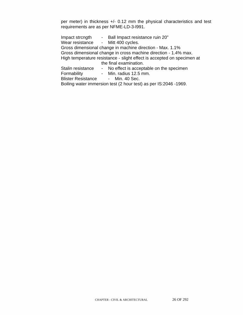
CHAPTER : CIVIL & ARCHITECTURAL 26 OF 292
per meter) in thickness +/- 0.12 mm the physical characteristics and test requirements are as per NFME-LD-3-l991. Impact strcngth - Ball Impact resistance ruin 20” Wear resistance - Mitt 400 cycles. Gross dimensional change in machine direction - Max. 1.1% Gross dimensional change in cross machine direction - 1.4% max. High temperature resistance - slight effect is accepted on specimen at the final examination. Stalin resistance - No effect is acceptable on the specimen Formability - Min. radius 12.5 mm. Blister Resistance - Min. 40 Sec. Boiling water immersion test (2 hour test) as per IS:2046 -1969.
CHAPTER : CIVIL & ARCHITECTURAL 27 OF 292
8.15 Decorative Laminated Sheets
Decorative thermosetting synthetic resin bonded laminated sheets are used in 1.5 mm thickness and are of type 1 with having one side bearing the decorative surface. The finish, shade, colour and-pattern can he mutually decided by the purchaser and supplier. Sheets are rectangular and unless otherwise specified, have square edges. The dimensional tolerance in all lengths and widths is +/- 1.25 mm per meter, +/- 0.25mm in thickness +/- 2 mm per meter length of the diagonal. Physical characteristics and test requirements arc as per appendix of IS:1046-1969. Resistance to dry heat - no blistering or appreciable surface deterioration or loss of gloss. Dimensional stability in low humidity test at 70 +/- 2° C for 24 hours less than 0.5% in length and width dimensions. Resistance to immersion in boiling water. Increase in weight - max 5% Increase in thickness - max 5% Resistance to staining for 24 hours with standing against agents specified in IS 2046 – 1969 specimen should not show blistering at the final examination. Cross breaking strength for 0.6 mm thick – 2000 kg per CM square. Cross breaking strength for 1.0 mm and 1.5 mm thick – min 4000 kg per CM square. Impact strength - min 0.035 kg fm Machinery test - no slitting or cracking
8.16 Epoxy Powder Coating
Epoxy powder used for coating can be of a standard shade or as that required. The specific gravity of powder 1.6 (+/- 0.2) gives a DFT of 50-60 microns. Pencil Hardness of 2H. Cross hatch Adhesion(DIN 553151) or GT -‘O’ glass @ 60 DIN 67530 of 80 +/- 5% for all standard except black, 45 +/- 5 for black It is able to withstand min 500 hour of salt spray test. Impact resistance of 150 kg cm.
CHAPTER : CIVIL & ARCHITECTURAL 28 OF 292
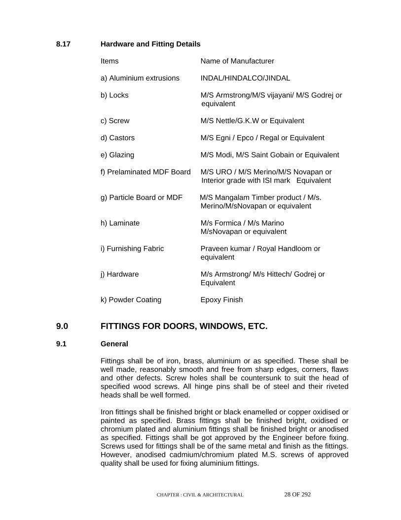
8.17 Hardware and Fitting Details
Items Name of Manufacturer a) Aluminium extrusions INDAL/HINDALCO/JINDAL b) Locks M/S Armstrong/M/S vijayani/ M/S Godrej or equivalent c) Screw M/S Nettle/G.K.W or Equivalent d) Castors M/S Egni / Epco / Regal or Equivalent e) Glazing M/S Modi, M/S Saint Gobain or Equivalent f) Prelaminated MDF Board M/S URO / M/S Merino/M/S Novapan or Interior grade with ISI mark Equivalent g) Particle Board or MDF M/S Mangalam Timber product / M/s. Merino/M/sNovapan or equivalent h) Laminate M/s Formica / M/s Marino M/sNovapan or equivalent i) Furnishing Fabric Praveen kumar / Royal Handloom or equivalent j) Hardware M/s Armstrong/ M/s Hittech/ Godrej or Equivalent k) Powder Coating Epoxy Finish
9.0 FITTINGS FOR DOORS, WINDOWS, ETC. 9.1 General Fittings shall be of iron, brass, aluminium or as specified. These shall be
well made, reasonably smooth and free from sharp edges, corners, flaws and other defects. Screw holes shall be countersunk to suit the head of specified wood screws. All hinge pins shall be of steel and their riveted heads shall be well formed.
Iron fittings shall be finished bright or black enamelled or copper oxidised or
painted as specified. Brass fittings shall be finished bright, oxidised or chromium plated and aluminium fittings shall be finished bright or anodised as specified. Fittings shall be got approved by the Engineer before fixing. Screws used for fittings shall be of the same metal and finish as the fittings. However, anodised cadmium/chromium plated M.S. screws of approved quality shall be used for fixing aluminium fittings.

CHAPTER : CIVIL & ARCHITECTURAL 29 OF 292
9.2 Hinges 9.2.1 Butt hinges These shall be mild steel but hinge (medium), brass butt hinges, extruded
aluminium alloy butt hinges or as specified. Type (light/medium/heavy weight) and size shall be as specified in the drawing or schedule of items. Brass / Aluminium and M.S butt hinges shall conform to Indian Standard Specification for butt hinges IS : 205-1992 and IS : 1341-1992 respectively. Hinges shall be finished bright or satin polished or anodised.
9.3 Sliding Door Bolts Mild steel sliding door bolts shall conform to IS : 281-1991 and are of 2
types, plate type and clip or bolt type. Plate type bolts shall have plates and straps stove enamelled black with hasp and bolt finished bright or copper oxidized or nickel / chromium plated. Clip or bolt type are copper oxidized or plated. All screw holes in the M.S bolts shall be countersunk. Diameter of bolt for plate type is 12mm and for clip type is 16mm.
Non ferrous metal sliding doors are of brass or aluminium alloy and shall
conform to IS:2681-1979. Brass sliding bolts are of 150 to 450mm size with bolt dia being 16mm for 150 to 300mm and 18mm for 375 and 450 size. Aluminium alloy sliding bolts are of size 200 to 450mm with 16mm bolt dia. Brass quality is finished satin, polished or plated and aluminium alloy bolts are anodised.
For both ferrous and non-ferrous metal bolts the size of the sliding bolt is
determined by the length of the bolt. 9.4 Door Rim Latch This shall be of mild steel, brass, aluminium alloy or as specified and of
sizes 75, 100, 125 and 150mm denoted by overall length of the body measured from outside face of the fore end to the rear end. These are of type 1 and type 2 and shall conform to IS : 1019-1974.
9.5 Tower Bolts Tower bolts may be of one of the following types and shall conform to IS :
204 (Part 1 and 2)-1991 and 1992.
i) Barrel tower bolts These shall be of bright finished/stove enamelled/ black painted mild steel
tower bolts, brass barrel tower bolts with cast brass barrel and rolled or drawn brass bolt/brass barrel tower bolts with barrel of extruded sections of brass and rolled or drawn brass bolt/brass barrel tower bolts with brass sheet barrel and rolled or drawn brass bolt. Aluminium barrel tower bolts with barrel and bolt of extruded section of aluminium alloy-bolts and barrel anodised.

CHAPTER : CIVIL & ARCHITECTURAL 30 OF 292
ii) Semi-barrel tower bolts
These shall be mild steel semi barrel tower bolts full cover/open type with mild steel sheet pressed barrel and cast iron/mild steel bolt. Bolt bright finished other parts stove enamelled black.
iii) Rivetted or spot welded tower bolts
These shall be mild steel tower bolts rivetted type with black flat and mild steel/cast iron bolt and open staple.
iv) Skeleton tower bolts
These shall be of bright finished / stove enamelled / black painted
mild steel or brass bright finished skeleton tower bolts with cast brass/extruded sections plate and staples and rolled or drawn brass bolt or Aluminium skeleton tower bolts with plates staples and bolt or extruded sections of Aluminium alloy plate and staple anodised.
9.6 Door Handles Door handles shall conform to IS : 208-1987 and shall be of 4 types. Type 1
is cast Iron / Brass / Aluminium or zinc alloy die casting and available in 75,100,125 150mm sizes. Type 2 is mild steel pressed oval in 75, 100,115 and 135mm sizes. Type 3 is mild steel present half oval in 75,90 and 100mm sizes. Type 4 is fabricated (brass / aluminium alloy) in 75,100 and 125mm sizes. The size of the handle shall be determined by inside (grip) size overall size and internal depth of the handles shall be as detailed in IS : 208-1987.
Finish for type 1 shall be satin/nickel plating, copper oxidising and bronze
finish for cast-brass and zinc die cast handles and stove enamelled black or copper oxidized for cast iron handles. Aluminium handles shall be anodized. Type 2 and 3 handles shall be stove enamelled black. For type 4 it shall be satin finish, nickel plating, copper oxidized and bronze finish for brass handles and anodizing for aluminium handles.
9.7 Mortice Lock and Rebated Mortice lock Mortice lock with latch and pair of lever handles shall have body of steel,
Aluminium alloy or brass and shall be right or left handed as shown in the drawing or as directed by the Engineer. It shall be of the best Indian make of approved quality and shall conform to IS: 2209 / 6607-1976/1972. The shape and pattern shall be approved by the Engineer. The size of the lock shall be determined by its length. The lock for single leaf door shall have plain face and that for double leaf door a rebated face. Lever handles with springs shall be mounted on plates and shall weigh not less than 0.5 kg per pair. These shall be of brass, finished, bright chromium plated or oxidised. The locks shall be of 65, 75 and 100 mm sizes.
9.8 Floor Door Stopper

CHAPTER : CIVIL & ARCHITECTURAL 31 OF 292
These are for the use of the door shutters of 30, 35,40 & 45mm thickness.
It is made of aluminium alloy/ brass with springs of phosphor bronze or hard drawn steel wire and tongue of aluminium/brass/nylon/ plastic. The floor door stoppers shall conform to IS : 1823-1980 and shall be best Indian make of approved quality. Width of cover plate is 40mm but its overall length is 140mm for 30 and 35mm thick shutters & 150mm for 40 and 45mm shutters. The body shall be cast in one piece and fixed to cover plate by brass or M.S screws. On the extreme end there shall be rubber cushion to absorb shocks. The extension of the door stopper shall be in flush with floor and be finished bright/satin/chromium plated or anodised.
9.9 Hooks and Eyes
These shall be of mild steel or hard drawn brass and shall generally conform to IS : 207-1964.
9.10 Casement Window Handles These shall be made of cast brass, steel protected against rusting,
aluminium, pressed brass or as specified. Casement handles for single leaf window shutter shall be left or right handed and shall weigh as specified.
9.11 Casement Peg Stays These shall be made of cast brass, steel protected against rusting,
aluminium, cast alloy or as specified. The stay shall be made from a channel section and shall be 300mm long with steel peg and locking bracket. The peg stay shall have three holes to open the window in three different angles. The shape and pattern of stays shall be approved by the Engineer. The peg stay shall be minimum 2mm thickness in case of brass and aluminium and 1.25 mm in case of steel.
9.12 Quadrant Stays These shall be made of cast brass, aluminium alloy, CP iron or as
specified. The shape and pattern shall be approved by the Engineer. It shall weigh as specified.
9.13 Fan Light Pivots These shall be made of mild steel, cast brass or aluminium alloy or as
specified and shall generally conform to IS : 1837-1966. The pattern and the shape of the catch shall be as approved by the
Engineer and size and finish shall be as specified. 9.14 Fan light catch These shall be made of mild steel, cast brass, aluminium alloy or as
specified and shall generally conform to IS : 364-1993. Steel springs of the catch shall be 0.90 mm dia, 6 coils, 12 mm internal diameter and 20 mm long. The pattern and the shape of the catch shall be as approved by the Engineer.
CHAPTER : CIVIL & ARCHITECTURAL 32 OF 292
9.15 Steel Frames
These shall conform to IS:4351-1976. The frames shall be manufactured from commercial mild steel sheets of 1.25mm thickness and are suitable for door shutters 30 to 40mm thick. The door frames are designated as per profile A, B and C.
Profile A Size 105x60mm : rebated for one set of shutters
Profile B Size 125x60mm : rebated for one set of shutters
Profile C Size 165x60mm : rebated for two sets of shutters.
Miscellaneous Items :
9.16 Putty The material shall be homogeneous paste and shall be free from dust and
other visible impurities. Putty shall conform to IS : 419-1967 for wood work. 10.0 METAL DOORS, WINDOWS, VENTILATORS AND ROLLING
SHUTTERS 10.1 General Materials used in the fabrication of doors, windows, and ventilators shall be
the best procurable and conforming to relevant Indian Standards.
CHAPTER : CIVIL & ARCHITECTURAL 33 OF 292
10.2 Steel Doors, Windows and Ventilators Steel sections used for fabrication of doors, windows and ventilators shall
be standard rolled steel sections specified in IS : 1038, IS : 1977, IS : 1361 or IS : 7452 year 1983, 1975, 1978 and 1990 respectively as appropriate or as specified in drawing and Schedule of Items. Rivets shall conform to IS : 1148-1982.
10.3 Aluminium Door, Windows and Ventilators Aluminium sections for fabricating doors, windows, ventilators, partitions
etc., shall be extruded sections conforming to IS : 1948-1961 & IS : 1949-1961 or as manufactured by Indian Aluminium Company Limited or approved equivalent The alloy used shall conform to Designation HE 9 - WP of IS : 733-1983.
10.4 Steel Rolling Shutters, Rolling Grills These shall conform to IS : 6248-1979. 10.5 M.S. Bolts etc. M.S. bolts, nuts, screws, washers, peg stays and other mild steel fittings
shall be treated for corrosion. Putty for glazing shall conform to IS : 419-1967. Glass panes and glazing shall conform to the specification detailed under this series.
10.6 Hardware and fixtures shall be as specified in the drawings or Schedule of
Items. All hardware and fixtures shall be able to withstand repeated use. Door closers shall be suitable for doors weighing 61 80 kg, unless otherwise stated. Each closer shall be guaranteed against manufacturing defect for one year and any defect found within this period shall be rectified or the closer replaced free of charge. Concealed door closers shall be either floor mounted or transom mounted, suitable for installation with metal doors. It shall conform to the performance requirements and endurance test stated in IS : 3564 1986 Appendix-A.
10.7 The mastic for caulking shall be of best quality from a manufacturer
approved by the Engineer. In general, the mastic for fixing of metal frames shall conform to IS : 1081-1960 and/or as approved by the Engineer.
CHAPTER : CIVIL & ARCHITECTURAL 34 OF 292
11.0 GLASS 11.1 General Plain, ground, frosted or rough cast wired glass shall be used as shown on
the drawing or as specified in the Schedule of Items. It shall be procured from a reputed source of manufacture and be of the best quality. All glass panes shall be free from flaws, specks, bubbles etc. Glass panes shall be of thickness 3mm or more as required. Weight of 3mm thick glass pane shall not be less than 7.5 Kg//sqm. The tolerance of glass panes, except wired glasses, in length and width shall be plus or minus 2 mm for 3 to 6.3 mm glass sheets. Tolerance in thickness of glass sheets shall be +/- 0.2mm for 3mm and 4mm thick glasses and +/- 0.3mm for 4.8, 5.5 and 6.3mm thick glasses.
11.2 Plain Transparent Glass Plain transparent glass for glazing and framing shall conform to IS: 2835-
1987. It shall be free from flaws, specks, bubbles or distortions. 11.3 Ground and Frosted Glass Glare reducing or heat absorbing glass shall be "Calorex" or approved
equivalent and special care shall be taken to grind smooth and round off the edges before fixing.
11.4 Thickness Glass shall have the following thickness, unless otherwise stated in the
Schedule of Items or drawings
Upto 60 cms x 60 cms ... 3 mm
do- of larger size ... 4 mm and 4.8mm
Sheet glass for doors ... 5.5 mm
Rough cast wired ... 6.4 +/- 0.4 mm
11.5 Inspection All glasses shall be subject to inspection on the site. Glass found to suffer
from defects shall be rejected. Samples submitted for inspection shall be selected so as to be representative of the consignment.

CHAPTER : CIVIL & ARCHITECTURAL 35 OF 292
12.0 PAINTS 12.1 General
All paints, varnishes, distemper or other surface coating materials shall be of approved quality conforming to the appropriate Indian Standard, wherever such standard is available, and be obtained from a manufacturer of repute. If there is more than one quality for one particular product, only first quality shall be used unless otherwise stated in the Schedule of Items.
12.2 Sampling and Testing The Engineer may, at his discretion, require samples of paint to be tested.
In such cases testing will be according to IS : 101 (Part 1 to 8) -1964 to 1993.
12.3 Storage Paints, primers, distempers and varnishes shall be delivered in sealed
containers. They shall be stored in cool dry condition to the satisfaction of the Engineer.
12.4 Paints for Priming Ready mixed paints for priming coats of steel and iron work shall either
comply with IS : 2074-1992 "Ready Mixed Paint", "Red Oxide Zinc Chrome Priming" or Red Oxide metal primer as specified. For wood work it shall be pink/white wood primer as specified by the manufacturer of the synthetic enamel paints, conforming to IS : 3536-1966.
12.5 Paints for finishing Ready mixed oil synthetic enamel paint of approved manufacturers like
Berger, Jenson & Nicholson, Shalimar, I.C.I., Asian, Garware and Goodlass Nerolac paints only shall be used unless otherwise specified. Paint shall be of first grade quality of the above manufacturers ie., Luxol Brolac, Superlac, Dulox gloss, Apocolite, Garcoat and Nerolac respectively.
If for any other reason, thinning is necessary, the brand of the thinner
recommended by the manufacturer, shall only be used with the specific permission of the Engineer.
Aluminium paint for general purpose shall be in Duel Containers. It shall be
of manufacturers as for synthetic enamel paints above.

CHAPTER : CIVIL & ARCHITECTURAL 36 OF 292
12.6 White wash White was shall be prepared from freshly burnt fat, white in colour lime
slaked on spot, conforming to IS : 712-1984 mixed and stirred with sufficient water to make a thin cream. Best and approved quality gum and ultra marine blue only shall be used in lime wash.
12.7 Colour wash Colour wash shall be prepared by adding mineral colours, not affected by
lime, to white wash. 12.8 Water proofing Cement Paint Cement paints shall comply with IS: 5410-1992 and shall be of approved
brand and manufacture like Snowcem India Ltd., Berger, Jenson & Nicholson & Shalimar paints. The shade shall be approved by the Engineer before its application.
12.9 Distemper Dry/ synthetic (acrylic) washable distemper of approved brand and
manufacture like Berger, Jenson & Nicholson, Asian, Shalimar, Garware & Goodlass Nerolac shall be used. The shade shall be approved by the Engineer before application of the distemper. and shall comply with IS : 427-1965 and IS : 428-1969.
12.10 Varnish Varnish for the finishing coat shall be copal finish or synthetic class varnish
of approved brand. Varnish for the under coat shall be flatting varnish of the same make as the top coats and shall be to the satisfaction of the Engineer.
12.11 Polish French spirit polish shall be of an approved make conforming to IS: 348-
1968. In case it is to be prepared on site, the polish shall be made by dissolving 0.7 kg of best, shellac in 4.5 litres of methylated spirit without heating. To obtain required shade pigment may be added and mixed. Shallac shall conform to IS : 5467-1986.
12.11.1 Wax polish for Wood work The polish shall consist mainly of waxes and Organic solvents with or
without water and shall be of smooth consistency, homogeneous, Semi-Solid mass and free from gritty materials. It shall not flow at ordinary temperature. It may be tinted with an oil soluble colour. The polish shall not crumble or dry too rapidly and shall produce non-tacky polished surface. The polish shall be amenable to smooth spreading on the furniture surface and the gloss shall appear on gentle rubbing with a soft polishing cloth.

CHAPTER : CIVIL & ARCHITECTURAL 37 OF 292
The wax polish shall conform to IS : 8542-1977. 12.11.2 Where wax polishing is to be prepared at site, it shall be prepared by
heating two parts of "Bee Wax" two parts of boiled linseed oil over a slow fire. When dissolved but still warm, one part of turpentine is to be added. The boiled linseed oil, bees wax and turpentine used shall be of approved quality and complying with IS : 77-1976, IS : 1504-1974 and IS : 533-1973 respectively.
12.12 Plastic (Acrylic) emulsion paint Plastic emulsion paint of approved manufacturers like Jenson & Nicholson,
Goodlass Nerolac, Shalimar, Berger, Asian and Garware paints only shall be used unless otherwise specified and shall comply with IS : 5411 (Part 1)-1974 & (Part 2)-1972 as applicable. Cement primer used for priming work both for oil bound distemper and plastic emulsion paint shall be of the same manufacture as that of distemper or plastic emulsion paint used. For dry distemper priming, whiting of approved quality shall be used.
12.13 Creosote oil or Coaltar Creosote It is primarily used for preservation of wood. It shall be a homogeneous
liquid and shall liquify completely on being warmed to 38 degree C with stirring and shall remain liquid on cooling down to 32 degree C and on standing at that temperature for 2 hours.
The material shall conform to IS : 218-1983. All persons handling the
creosote oil should be fully aware of the hazards involved in handling . Skin should be protected from coming in direct contact and eyes should be protected by using safety goggles while handling the material.
12.14 Coaltar Black Paint Coaltar paint film protects surfaces by serving as a barrier against the
action of moisture and other corrosive agents. Coaltar black paint is generally used as a protective and anti corrosive paint of iron and steel as well as protection of other building surfaces. For this it has to be applied under proper condition and on suitably prepared surface. Coaltar should be applied by brush only and is not recommended for locations which are not likely to be well ventilated. Coaltar paint shall conform to IS : 290 1961.
The material is of two types : Type A Quickly drying and Type B Slow
drying. It shall be a homogenous black solution type paint consisting of a base prepared by blinding suitable grades of Coltar pitch, washed free from ammoniacal liquor, tar acid bases etc. Consistency, permeability, thickness and surface preparation etc. shall be as per para 5 and A-2 of the above code.
12.15 Floor Polish - Paste The polish shall consist mainly of waxes and organic solvents with or
without water.
CHAPTER : CIVIL & ARCHITECTURAL 38 OF 292
The paste floor polish shall be of smooth consistency, homogenous, semi-
solid-mass and free from gritty material. It shall not flow at ordinary temperature. It shall be so constituted and prepared that on application by means of a clean cloth, it shall spread easily and evenly and shall give with minimum buffing a firm and glossy surface free from greasiness or tackiness. The polish film after spreadng with a cloth shall not take more than 10 minutes to dry. The polished floor shall neither be slippery nor show any resistance to easy walking.
Floor polish paste shall conform to IS : 8591-1977. 13.0 WATER PROOFING MATERIALS 13.1 Integral Cement Waterproofing Compounds Integral cement waterproofing compounds, i.e. admixture for waterproofing
purposes shall fully comply with the requirements of IS : 2645-1975. Properties like permeability, setting time, compressive strength shall be in accordance with the requirements of this code when tested as per procedure laid therein. Calcium chloride content of the product used shall be made known to Engineer before use.
13.2 Bitumen The bitumen bonding material for waterproofing shall conform to the
requirements laid down in IS : 702-1988 or IS : 93-1992 or IS : 217- 1988 or IS : 454-1961 depending upon whether industrial bitumen, paving bitumen or cutback bitumen is used. For selecting the particular type and grade of bitumen to be used the relevant item in Schedule of Items shall be referred to.
CHAPTER : CIVIL & ARCHITECTURAL 39 OF 292
13.3 Bitumen Primer Bitumen primer used for application to concrete and masonry surfaces and
bitumen for the purpose of waterproofing shall conform to requirements given in IS : 3384-1986 and pass tests in accordance with the procedure laid down in appropriate IS mentioned in Table-I of IS : 3384-1986. Bitumen primer should be free from water and shall preferably ;be made from the same grade of bitumen as used in bonding.
13.4 Bitumen Felt Bitumen felts used for water proofing purposes shall be as specified in IS:
1322-1982. Physical properties shall conform to the requirements and tests shall be carried out as per procedure laid down in IS :1322- 1982. Base, (whether fibre or Hessian), type and grade of felt shall be as mentioned in the relevant items under Schedule of Items. Unless otherwise stated, hessian base felt Type-3, Grade-2 shall be used.
13.5 Bitumen Mastic Bitumen mastic used for water proofing of roofs shall have the physical
properties as mentioned in IS : 3037-1986 when tested with the procedure laid down in appropriate IS mentioned in IS : 3037-1986.
13.6 Bituminous Compounds Bituminous compounds when used for waterproofing of porous masonry,
concrete floors, walls and roofs shall conform to the requirements of IS : 1580-1991. Physical properties shall be governed by the requirements of this code when tested in accordance with the procedure laid therein.
13.7 Surface Application Materials Waterproofing material for application on mortar or concrete surface shall
conform to IS: 9862 1981. The primer shall be suitable for spray or brush application. It shall have properties enabling it to penetrate through pores or cracks and fill them up, making the surface impervious.
13.8 Polymer based paints The materials used shall be high polymer based chloride and sulphide free
cement and waterproofing additions and epoxy based waterproofing paints as per manufacturer's specification and approved by Engineer.
CHAPTER : CIVIL & ARCHITECTURAL 40 OF 292
13.9 Fibre glass R. P. Tissue
The fibre glass R.P. tissue is a thin flexible uniform mat, composed of glass fibre in an open porous structure bonded with a suitable inert material compatible with coal tar, asphaltic enamel and oil plastic based wall paint. The fibrous glass mat is reinforced with continuous filament glass yard at 3/8" (10mm) pitch in the longitudinal direction.
PHYSICAL PROPERTIES
i) Weight The average weight of fibre glass R.P.
tissue shall not be less than 50 gms/sq.sm.
ii) Thickness The fibre glass R.P. tissue shall have a thickness not less than 0.4mm.
iii) Tear Strength The tear strength shall be not less than 900 grams in the transverse direction.
iv) Breaking Strength This shall have a minimum breaking strength of 13 lb/in (2.32kg/cm) in the longitudinal direction.
v) Porosity This shall have a porosity when related to pressure difference across the sample of not less than 0.022" (0.56mm) and not more than 0.76" (1.92mm) of water guage at an air velocity of 200fpm.(100cm/sec.).
vi) Pliability There shall be no cracking of the tissue mat when bent over a 1/8" (3.2mm) radius after immersing for 10-15min. through a 90 degree arc.
vii) Temperature The fibre glass tissue shall be Resistance under a load of hot bitumen at 530 degree F (276 degree C) for one minute.
13.9.1 Primer Primer shall conform to requirements laid down in IS : 3384-1986. It is to be
prepared by blending turpentine and blown grade bitumen in the ratio of 60:40 by weight.
CHAPTER : CIVIL & ARCHITECTURAL 41 OF 292
13.9.2 Blown Materials Blown grade bitumen shall be conforming to IS : 702-1988 and residual
grade bitumen conforming to IS:73 respectively. This shall be prepared by heating to correct working temperature.
13.9.3 Surface finish Pea sized gravel/grit 6mm and down. 13.10 P.V.C. Membrane/Sheets Polyvinyl chloride sheets for the purpose of water proofing and other
underground use are specially developed sheets made from the compounded resin of grade MP/DP/CR-02 and shall be resistant to the passage of gross water and water vapour. It shall be corrosion resistant and resistant to a wide range of acidic and alkali reagents, saltpetre action, salt water and ultra violet rays etc. PVC sheets manufactured by approved and reputed firms like Maxlok Polymer Ltd. shall only be used
The sheets shall consist of Knobs or Lugs jutting out of the sheets in a grid
fashion so as to provide a perfect grip in the mortar and concrete. Sheet thickness, spacing of the knobs and their projection from the sheet shall be as specified in the item. The sheets shall be of maximum practicable length and width unless otherwise specified.
The adhesive used for jointing shall be of approved quality and of grade C-
02. The sample of the material shall be got approved before use. 13.10.1 Properties
i) Chemical Composition : Resin Plasticiser Inhibitor Stabiliser UV Barrier.
ii) Thickness
: Not less than 0.25 mm
iii) Rupture/Tensile Strength
: Not less than 225Kg/cm2
iv) Adhesive bond Strength [width]
: : Not less than 7.1 Kg/cm
v) Elongation at Break : 130%
13.11 Torchable polymeric membrane
The same shall be as per manufacturer specification.

CHAPTER : CIVIL & ARCHITECTURAL 42 OF 292
14.0 WATER BAR 14.1 General Water bar for use in construction/expansion joints in concrete and
reinforced concrete structures shall be of copper sheet, galvanised steel sheet, rubber or PVC as shown in drawing or described in the Schedule of Items. It shall be subject to approval of Engineer.
14.2 Jointing
The water bar shall have dimensions as shown in drawing. Where water bars are required to be lengthened or otherwise jointed the joining shall be done in such a way as to achieve a perfectly watertight joint.
15.0 LEAD 15.1 General Lead for joints in cast iron spigot and socket pipes shall be melted from
pure soft pig lead conforming to Type-I of IS : 782-1978. "Caulking Lead". Where lead wool is allowed for caulking, it shall be equal to or better than Type-II of IS : 782-1978. Lead flashing shall conform to IS : 405 Part I&II-1992.
16.0 BUILDING PAPER 16.1 Building paper shall be bitumen impregnated paper conforming to IS: 5134
1977, or such other as may be approved by the Engineer. 17.0 FILLING MATERIAL 17.1 General Filling material shall conform to what is shown in drawing, described in the
Schedule of Items or otherwise directed by the Engineer. Earth or sand for filling under floors shall correspond to those described elsewhere in these specifications.
17.2 Mastic Bitumen Mastic Bitumen shall conform to IS : 3037-1986 or IS : 5871-1987 as
appropriate.
CHAPTER : CIVIL & ARCHITECTURAL 43 OF 292
17.3 Flexible Boards Flexible boards for use in expansion joints shall correspond to the
description given in drawing or the Schedule of Items or the instruction of Engineer.
18.0 DRAINAGE & SANITATION (INTERNAL) 18.1 General All materials, pipes, specials, fittings, fixtures etc., to be used in the works
shall be of best quality and class specified in relevant IS Code. Where specified these shall be of specific manufacture and quality and shall be procured from manufacturer or their accredited stockists and be marked with manufacturers' names and trade mark. Contractor shall submit to the Engineer samples of all materials, pipes, specials, fittings fixtures for approval before use in the works. Such approved samples shall be retained by the Engineer till completion of works. Pipes and Specials may be any or combination of following types:-
i) PVC Pipes
ii) Stone Ware Pipes
iii) Sand Cast Iron Pipes for soil waste & Ventilation
iv) CI Pipes for rain water
v) AC Pipes for rain water
vi) R.C.C Pipes
18.1.1 High density PVC pipes and fittings This shall conform to IS : 4984-1987 and IS : 8008 (Part 1 to 7)-1976
unless otherwise specified. 18.2 PVC Waste Pipe This shall conform to IS : 4985-1988 unless otherwise specified. 18.3 Stoneware Pipes & Fittings All stoneware pipes, bends, gully traps and sewer traps shall be of the best
salt glazed variety inside and outside, hard burnt dark grey colour, perfectly sound, free from fire cracks and imperfection of glaze, truly circular in cross section, perfectly straight, of standard nominal length and depth of socket and barrel. These shall be of approved manufacture and shall comply with the requirement of IS: 651-1992. These pipes shall be of grade AA unless otherwise specified.
18.4 Sand Cast Iron Pipes & Fittings conforming to IS : 1729-1979 All soil waste and vent pipes and fittings used in the work shall be cast iron
and shall conform to IS: 1729-1979. The pipes shall have spigot and socket

CHAPTER : CIVIL & ARCHITECTURAL 44 OF 292
ends, with bead on spigot end and shall be with or without ears. The pipes shall be free from cracks and other flaws. The interior of the pipe and fittings shall be clean, smooth painted inside and outside with DR Angas smiths solution or other approved anti-corrosive paint.
The standard weights and thickness of pipe shall comply with the requirements of IS: 1729-1979. The tolerance on wall thickness and weight shall be minus 15 percent and minus 10 percent respectively. Pipes weighing more than the nominal weight given below may be accepted provided they comply in every other respect.
Weight per piece in Kg. excluding ears
Overall length Nominal size
1500 mm 1800 mm 2000 mm 50 9.56 11.41 12.65
75 13.83 16.52 18.37
100 18.14 21.67 24.15
150 26.70 31.92 35.66
Specials and Fittings shall include bends, offsets, branches of various
types, junctions etc., as required for the work which shall be provided according to drawings and directions of the Engineer. B.M. trap shall have water seal as per I.S. provisions.
The specials and fittings shall be provided with access doors where so
specified or directed by the Engineer. The access door fittings shall be of proper design so as not to form cavities in which the filth may accumulate. Doors shall be provided with 3 mm thick rubber insertion packing, and when closed and bolted they shall be water tight. The access doors shall have MS studs and bolts or screws or bolts and nuts.
18.5 Cast Iron Pipes & A.C. pipes : Rainwater pipe 18.5.1 Pipes shall be of approved manufacture, true, smooth and cylindrical, their
inner and outer surfaces being as nearly as practicable concentric and shall conform to IS : 1230-1979. These shall be sound and uniform casting, free from laps, pin holes or other imperfections and shall be neatly finished inside and outside. The ends of pipes shall be reasonably square to their axis.
18.5.2 Dimensions CI rain water pipes shall be of the dia specified in the description of the item
and shall be in full lengths of 1.8 metres including socket ends of the pipes, unless shorter lengths are required at junctions with fittings. The pipe lengths shall in each case be with sockets. The pipes shall be supplied without ears unless otherwise specifically mentioned.
The pipes supplied shall be factory painted with a tar based composition
both inside and outside which shall be smooth and tenacious unless specified otherwise.
CHAPTER : CIVIL & ARCHITECTURAL 45 OF 292
Every pipe shall ring clearly when struck all over with a light hand hammer.
When shorter pipes are cut from full lengths they shall be cut with a hacksaw.
Where the pipes are to be embedded in masonry they shall be of Class of
pipes as are used for soil and vent pipes. For the weights of different sizes of these pipes, the specifications under SCI and vent pipes may be referred to.
18.5.3 A.C. pipes and fittings the pipes and fittings shall be of approved
manufacture and shall conform to IS:1626. These shall be homogeneous and free from cracks and other defects. The pipes shall be straight, smooth and regular in thickness.
The diameter of the pipe shall be as specified. The fittings like heads,
bends of different degrees, offsets of different projections, shoes and junctions shall be of the type, diameter and size as required for the work. The pipes shall be used in full lengths as far as possible.
18.6 Sanitary appliances Sanitary appliances like I.W.C/E.W.C pans, wash basin, urinals and sinks
etc. shall be made of vitreous china or fire clay as specified. These shall be of Hindustan Sanitary ware or Parry ware make unless otherwise specified and to be approved by the Engineer. These shall conform to A class quality of IS : 2566 (Part 1 to 15)-1972 to 1985 and IS : 771 (Part 1 to 15) –1979 & 1985 respectively.
CHAPTER : CIVIL & ARCHITECTURAL 46 OF 292
18.6.1 European Pattern W.C. Unless otherwise specified, these shall comprise of :
a) White 'glazed earthenware wash down closet set with 'S' or 'P' trap of standard size.
b) 'Duco' spray painted 12.5 litres mosquito proof low level M.S or C.I
flushing cistern with valveless siphon, 15 mm ball cock, C.P. brass unions & couplings for the 32 mm dia flush pipe, 20 mm dia overflow PVC pipe with mosquito proof cover etc.
c) 'Duco' spray painted 1 1/4" (32 mm) dia G.I. telescopic flush pipe
with buffer clamp, holder bat clamp and 38mm dia PVC pipe or 35/40mm O.D. high density polythene flush pipe with buffer clamp, holder bat clamp.
d) Approved quality solid plastic W.C. seat and cover, bar hinges,
screws bolt, rubber buffers conforming to IS : 2548 (Part 1&2)- 1983.
e) 15 mm PVC connection pipe with brass couplings at both ends and
15 mm brass CP cock. f) Hard wood wooden blocks or other suitable fixing arrangement with
screws and detofix for fixing WC in floor and putty joint with flush pipe and soil pipe.
18.6.2 Indian Pattern W.C. Unless otherwise specified these shall comprise of :-
a) White glazed earthenware WC pan back entry type. b) White glazed earthenware 'P' or 'S' trap with or without vent.
c) 12.5 litres approved make mosquito proof M.S.high level flushing
cistern with valveless siphon, 15 mm ball cock, galvanised iron chain handle, cast iron brackets with wall plugs, brass unions and couplings for flush pipe, 20 mm dia overflow PVC pipe with mosquito proof cover etc.,
d) 32 mm dia GI telescopic or 35/40 mm O.D high density PVC flush
pipe with holder bat clamps. e) One pair of white glazed earthen ware foot rest set in cement mortar
1:3. f) 15 mm PVC connection pipe with brass couplings at both ends and
15 mm brass stop cock. 18.7 Wash Hand basin

CHAPTER : CIVIL & ARCHITECTURAL 47 OF 292
Unless otherwise specified these shall comprise of :-
a) White glazed earthenware basin with 2 nos. Concealed Cast Iron Brackets with wall plugs.
b) 1 no. 15 mm C.P. brass pillar tap. c) 32 mm C.P. brass waste fitting, C.P. brass chain and rubber plug. d) 32 mm PVC waste pipe with brass couplings/32 mm C.P. bottle trap. e) 15 mm PVC connection pipe with brass couplings and 15 mm brass
stop cock.
18.8 Flat Back Lipped Urinal Unless otherwise specified these shall comprise of:-
a) White glazed earthenware urinal basin back type. b) CI/M.S mosquito proof high level automatic flushing cistern of
capacity as specified in the Schedule of Quantities with all accessories, cast iron brackets with wall plugs, brass unions and coupling for flush pipe, 20 mm dia overflow pipe with mosquito proof cover.
c) 25 mm dia CP brass flush pipe and spreaders with wall clips and
brackets. d) 15 mm PVC connection pipe with brass couplings joint at both ends
and 15 mm brass stop cock. e) 32 mm C.P. brass outlets complete with PVC waste.

CHAPTER : CIVIL & ARCHITECTURAL 48 OF 292
18.9 Mirror Frames Mirror frame where specified shall be of fibre glass of approved shape,
size, colour and make. 18.9.1 Mirror shall be of superior glass with edges rounded off or leveled as
specified. It shall be free from flaws, specks or bubble and its thickness shall not be less than 5.0 mm. The glass for the mirror shall be uniformly silver plated at the back and shall be free from silvering defects. Silvering shall have a protective uniform covering of red lead paint.
18.10 Toilet Shelf 18.10.1 Glass shelf unit shall consist of an assembly of glass shelf, anodised
aluminium / CP brass guard rail and supporting brackets. The shelf shall be of glass of best quality with edges rounded off and shall be free from flaws, specks, bubbles and of thickness not less than 5.0 mm. The shelf shall have guard rail, resting on rubber washers on glass plate.
18.10.2 Ceramics shelf shall be of shape, size and design as specified in the
Schedule of Items. 18.11 Towel Rail Towel rail shall be of CP brass / anodised aluminium with two brackets of
same material, diameter and length as specified. 18.12 Soap Container Soap container shall be of C.P brass, PVC with cp brass brackets of
approved make and design. 18.13 CP Flush Valves for EWC The CP flush valve for EWC shall be of "Jaquar" brand of Jaquar & Co.,
'ACCO' brand of Asia Continental Metallwaren Fabric or equivalent quality. 18.14 CP Flush Valve for Urinals CP flush valve for urinal shall be of "Jaquar" brand of Jaquar & Co., 'ACCO'
brand of Asian Continental Metallwaren Fabric or of equivalent quality. 18.15 Gully Trap Each gully trap shall have one C.I. grating 150 mm x 150 mm and one
water tight pre-cast R.C. cover 300 x 300 x 40 mm thick with 1:1 1/2:3 mix concrete (one cement: one and half sand : 3 stone chips 20 mm down) including neat cement finish.
18.16 CI Manhole Covers & Frames These shall be of light or medium duty (LD or MD) as specified in

CHAPTER : CIVIL & ARCHITECTURAL 49 OF 292
Schedule of Items and of cast iron with raised chequered design, lifting key
and key hole and shall be coated with black bituminous base material,. Light duty covers and frames shall be of either rectangular type, single seal, pattern 1 and 2 having minimum weight of cover and frame 38 Kg and 25 Kg. respectively or with double seal, minimum weight of cover and frame being 52 Kg. These may be of square type also. Single seal with clear openings of 455 and 610 mm with minimum weight of cover and frame being 20 Kg and 38 Kg respectively, double seal of same openings shall have minimum Wt. of cover and frame 30 Kg and 55 Kg respectively. Medium duty covers and frames shall be either of circular type with 500 and 560 mm clear openings and minimum Wt. of cover and frame 116 Kg and 128 Kg respectively or of rectangular type with minimum Wt. of cover and frame 144 Kg.
The C.I. manhole covers and frames shall conform to IS : 1726-1991. 18.17 Flushing Cisterns Manually operated high level and low level flushing cisterns are of 5 litre
and 10 litre capacities, both single flush and dual flush type. The cisterns shall conform to IS : 774-1984 and be made of Cast Iron, Vitreous China or enamelled pressed steel. The cisterns shall be mosquito-proof.
The thickness of the body including cover shall be not less than 5 mm for
Cast Iron and 6 mm for Vitreous China Cisterns. Steel and lead flush pipe shall have internal diameter of 32 plus or minus 1 mm for high level cisterns and 38 plus or minus 1mm for low level cisterns. For high density polyethlyne and unplasticised PVC pipes the outside diameter of the pipe shall be 40 mm. In case of PVC plumbing pipes the outside diameter of the pipes shall be 40mm for high level and 50mm for low level cisterns. Steel flush pipes shall be hot dip galvanized electroplated or vitreous enamelled.
The flush pipe shall be securely connected to the cistern outlet and made
airtight by means of a coupling net. Float valve shall conform to IS : 1703-1977 or IS : 12234-1988. Polyethylene float valve shall conform to IS : 9762-1981.
Cast Iron Cisterns shall be painted and finished in accordance with
recommendation made in IS : 1477 (Part 1&2)-1971 or shall have a coating of enamel.
In general, Materials Construction and operational and performance
requirements shall be as specified in para 3, 4 and 6 of IS : 774-1984. 18.18 Plastic Seats & Covers for Water Closets These shall conform to IS : 2548 (Part 1&2)-1983 and shall be either of
thermo-set or of thermo-plastic quality. Thermo-set Seats and Covers are moulded from phenolic plastics (Type A)
or Urea Formaldehyde (Type B). Thermo-plastic Seats and Covers are also
CHAPTER : CIVIL & ARCHITECTURAL 50 OF 292
of Type A, moulded from Polystyrene or Type B, moulded from Polyprophlene.
Underside of the seats may be either flat or recessed and colour shall be as
agreed. Table Dimensions of the seats and covers shall be as per Table-I of the Code (both Part 1&2). Hinging device may be either of the following materials :
i) Bronze or Brass with Nickel Chromium Plating
ii) Mild Steel with Nickel Chromium Plating
iii) Aluminium alloy with anodic coating
iv) Suitable plastic with reinforcement.
19.0 WATER SUPPLY & PLUMBING (INTERNAL) 19.1 General This section deals with the specification of material for pipes, fittings,
fixtures etc., to be used in water supply works. All materials, pipes, fittings, fixtures to be used in the works shall be of the
best quality and of the class specified in various clauses herein under. Where specified these shall be of specific manufacture and quality and shall be procured from the manufacturer or their accredited stockist and be marked with manufacturers name and trade marks. The Contractor shall submit to the Engineer samples of all pipes, fittings, fixtures for approval before being used in the works. Such approved samples shall be retained by the Engineer till completion of works.
Pipes and pipe fittings may be of any or combination of following types:
i) Wrought iron galvanised pipe
ii) PVC pipes
iii) Cast iron pipes
iv) Steel pipes coated with bitumen composition inside and galvanised outside.
v) Reinforced concrete pipes
vi) Asbestos cement pipes
vii) Pre-stressed concrete pipes
viii) Lead pipe (not to be used for potable water)
19.2 Galvanised Iron Pipes and Fittings
Generally pipes for installations in buildings shall be medium quality malleable steel galvanised pipe 'B' class for cold water supply and 'C' class for hot water supply, having threaded ends with socket at one end.
CHAPTER : CIVIL & ARCHITECTURAL 51 OF 292
The details of standard medium quality "B" class pipes and sockets
regarding nominal bore thickness and weight in kg/m are given below:-
Dimension of Pipe Dimension of ordinary socket
Pipe Dia (Nominal
Bore) Max. (outside dia)
Min.
Thick--
ness Outside dia (approx.)
Min. length
Wt. of Pipe plain end
mm mm mm mm mm mm Kg/m 15 21.8 21.0 2.65 26.90 34 1.21
20 27.3 26.5 2.65 33.70 36 1.57
25 34.2 33.5 3.25 42.00 43 2.42
32 42.9 42.0 3.25 51.00 48 3.11
40 48.8 47.9 3.25 57.00 48 3.59
50 60.8 59.7 3.65 70.00 56 5.07
65 76.6 75.3 3.65 88.00 65 6.49
80 89.5 88.0 4.05 101.60 71 8.43
Note :- Manufacturing tolerances shall be permitted on tubes and sockets in
addition to above as per IS : 1239 (Part 1&2) 1990 to 1992. The galvanised iron pipes shall be of approved make and conform to
IS:1239 (Part 1&2) 1990 to 1992 and of tested quality. The GI pipes shall be of threaded ends with a socket at one end only. The fittings for GI pipes shall be either galvanised wrought iron or galvanised malleable iron.
CHAPTER : CIVIL & ARCHITECTURAL 52 OF 292
19.3 R.C.C, Asbestos, Prestressed Pipes and Fittings These shall be of approved manufacture and quality and shall conform to
IS : 458 1988, IS : 1592 1989, IS : 9627 1988 & IS : 784 1978 respectively.
19.4 Cast Iron Pipes and Fittings The cast iron pipes shall be of approved manufacture and quality and shall
conform to IS: 1536 1989 "Centrifugally Cast (Spun) iron pressure pipe and/or IS : 1537 1976". Vertically Cast Iron pressure pipe for water, gas and sewage. CI fittings shall conform to IS : 1538 (Part 1 to 23) 1976.
19.5 Steel Pipes This shall conform to IS: 1239 (Part 1&2) 1990 to 1992) and IS : 3589-
1991. Steel pipes shall be coated with bituminous composition inside and galvanised outside.
19.6 Bib Tap and Stop Tap Bib tap and stop tap for water services shall be of brass screw down type
and shall conform to IS: 781. Minimum finished weight of bib and stop taps shall be as given below:
No. of size
(mm)
Bib taps (kg)
Stop tap (kg)
10 0.30 0.35
15 0.40 0.40
20 0.75 0.75
25 1.25 1.30
32 - 1.80
40 - 2.25
50 - 3.85
The taps shall be tested under internal hydraulic pressure of at least 20
kgf/cm2 and maintained at the pressure for a period of at least two minutes during which period it shall neither leak nor sweat
19.7 Valves Unless otherwise mentioned in the Schedule of Quantities these shall be
copper alloy gate, globe and check valve of nominal sizes 8 to 100mm and shall conform to IS : 778 1984. Valves shall be of class 1 and class 2, suitable upto a temp. of 45 degree C and can sustain non shock working pressure upto 1.0 and 1.6 MPA respectively. They shall have screwed or flanged ends. All the metal parts shall be of brass/brass alloy except hand wheel of Cast Iron or other approved quality.
CHAPTER : CIVIL & ARCHITECTURAL 53 OF 292
19.8 Shower Rose The shower rose shall be of heavy quality chromium plated brass with flat
bottom, of diameter 100 mm or as specified with uniform perforations. 19.9 Storage Tank Storage tank shall be either pressed steel, Galvanised iron, R.C.C or PVC
of specified sizes, capacities, make, manufacture as specified in Schedule of Items. It shall have facilities for connecting inlet, outlet overflow and washout pipes and a top cover. Where tanks are to be fabricated by the Contractor the fabrication/R.C.C detailed drawings shall be got approved by Engineer.
19.10 Miscellaneous items 19.10.1 Half round channel This shall be made of vitreous china channel with or without outlet/stop end
as specified in Schedule of Items and shall be of approved manufacture. 19.10.2 Urinal partition This shall be made of vitreous china or R.C.C. with mosaic finish or marble
as specified and shall be of approved make and quality. 20.0 EXTERNAL SEWERAGE & DRAINAGE Unless otherwise specified CI pipe and specials, caulking lead, SW pipe,
RCC pipe shall conform to the following. 20.1 C.I. Pipes
i) C.I. pipe shall conform to IS : 1536 - 1989 or/and IS : 1537 – 1976 of class as specified in Schedule of Items.
ii) C.I. pipe fittings shall conform to IS : 1538 (Part 1 to 23) -1976 as
specified in Schedule of Items.
iii) Bolts and nuts shall be hexagonal bolts and nuts conforming to IS : 1363 (Part 1 to 3) - 1992.
20.2 Washers Spring washers conforming to IS : 3063 - 1972 shall be used near the pumps
to take care of vibration. In other places plain washers conforming to IS : 2016 - 1967 shall be used.
20.3 Gaskets
CHAPTER : CIVIL & ARCHITECTURAL 54 OF 292
Gaskets shall be reinforced rubber sheet or compressed fibre board
conforming to IS : 638 - 1979 of thickness between 1.5mm to 3mm or as specified.
20.4 Caulking Lead Lead for the spigot and socket joints shall conform to IS : 782 - 1978. 20.5 Salt Glazed Stone Ware Pipes Salt glazed stone-ware pipes used shall conform to IS : 651 - 1992 and shall
be laid as per IS : 4127 - 1983. The pipes shall be of grade AA unless otherwise specified.
20.6 Steel Pipes
Steel pipes and fittings used for encasing shall conform to IS : 1239 (Part 1&2) - 1990 to 1992 medium Class upto 150 mm dia and as per IS : 3589 - 1991 for pipes of dia 200 mm and above. For pies of dia 200 mm and above fittings, if required shall be fabricated from pipes itself.
20.7 Cast Iron Manhole Covers & Frames These shall be of medium or heavy duty (M.D. or H.D.) as specified in
Schedule of Item and of Cast Iron with raised chequered design, lifting key and key hole and shall be coated with black bituminous base material. Medium duty covers and frames shall be either of circular type with 500 mm clear opening and minimum weight of cover and frame 116 Kg and 128 Kg respectively or of rectangular type with minimum weight of cover and frame 144 Kg.
Heavy duty covers and frames shall be either of circular type with clear openings of 500 and 560 mm and 170 and 208 Kg weight respectively or of double triangular type with clear openings of 500 and 560 mm and 229 and 255 Kg weight respectively.
The CI manhole cover and frames shall conform to IS : 1726 - 1991.
CHAPTER : CIVIL & ARCHITECTURAL 55 OF 292
21.0 ROAD 21.1 General Roads shall be understood to include road bed, the wearing surface, berms,
foot-paths, kerbs, culverts and bridges. 21.2 Soling Stones Material for soling shall be natural stone boulders or crushed blast furnace
slab. Stones for soling shall be of height equal to thickness of the soling with tolerance of plus or minus 25mm and shall not have a base area of less than 250 sq.cm. nor more than 500 sq.cm. and the smallest dimension of any stone shall not be less than half the largest dimension. Stones shall be tough, angular, durable and generally free from flat, elongated, soft and disintegrated particles. They shall also be free from dirt or other objectionable matter and be obtained from quarries approved by the Engineer.
Crushed slag obtained from air-cooled blast furnaces slag shall be angular,
of reasonably uniform quality and density and generally be free from any thin, elongated, and soft pieces, dirt or other objection able matter. The density of slag should not be less than 1.12 gm/cc and glassy material shall not exceed 20%. Water absorption when determined in accordance with IS:2386 (Part-III) - 1963. "Methods of Tests for Aggregates for Concrete : Specific Gravity, Density Voids, Absorption and Bulking", shall not exceed 10%.
21.3 Coarse Aggregate for Water Bound Macadam Coarse aggregate for water bound macadam shall be natural gravel, crushed
stone obtained from approved quarries or crushed blast furnace slag. Crushed stone shall be hard, durable, tough and of uniform quality, generally free from flat, elongated, soft and disintegrated particles. It shall have sharp edges and also not have excess of dirt and other objectionable matter. When tested as per IS: 2386 (Part-IV) - 1963 for Los Angeles Abrasion Value or Aggregate Impact Value, the limiting values shall be 50% and 40% respectively for base course and 40% and 30% respectively for surfacing course. The flakiness index shall not exceed 15% when tested in accordance with IS: 2386 (Part-I)-1963 "Methods of Test for Aggregates for Concrete : Particle size and Shape". Crushed slag aggregates shall meet the requirements given for soling stones from blast furnace slag.
Size and grading requirements of coarse aggregates shall be as specified in
Table-2 of IRC : 19 - 1981, "Standard Specification and Code of Practice for Water Bound Macadam". The grading number of the table shall correspond to the following layer thicknesses :
Grading Number Size Range Layer Thickness
1 90 mm to 40 mm More than 90 mm

CHAPTER : CIVIL & ARCHITECTURAL 56 OF 292
2. 63 mm to 40 mm 90 mm to 75 mm
3. 50 mm to 20 mm 75 mm to 50 mm 21.4 Screenings Screenings used for filling voids in coarse aggregates for water bound
macadam shall generally be of the same material as the coarse aggregate. Non-plastic materials such as Kankar nodules, moorum or gravel (other than river bore rounded aggregates) may be used, provided that the liquid limit and plasticity index are below 20 and 6 respectively. The fraction passing 75 microns sieve shall not exceed 10%. Size and grading of screenings shall be as specified in Table-3 of IRC-19 - 1981. Type-A screening shall be used for grade number 1 coarse aggregate. Type-B screenings shall be used for grade number 3. Either Type-A or Type-B screenings may be used for grade number 2.
21.5 Stone Chips for Bituminous Surfacing Coarse aggregate shall consist of crushed stone, crushed slag or crushed
gravel (Shingle) retained on 2.36 mm sieve. The aggregates shall be clean, strong, durable and fairly cubical, free from disintegrated pieces, organic and other objectionable matter. The aggregates shall preferably by hydrophobic and of low porosity. The mechanical properties and grading shall be in accordance with IRC-29 - 1988 "Tentative Specifications for 4 cm Asphaltic Concrete Surface Course", having aggregate impact value 30%, Flakiness Index 25% and graded between 20mm and 2.36 mm.
21.6 Sand Sand for use as fine aggregate in bituminous surfacing shall consist of
crushed screenings, natural sand or a mixture of both, passing a 2.36mm sieve and retained on 75 micron sieve. It shall be clean, hard, durable, uncoated and dry, free from injurious, soft or flaky pieces and organic deleterious substances.
21.7 Binder Binding material for water bound macadam shall consist of fine grained
material such as stone dust, kankar modules or moorum. The plasticity index shall be between 4 to 9 when water bound macadam is to be used as surface course and upto 6 when used as sub/base or base course.
21.7.1 Paving Bitumen It shall conform to IS : 73 - 1992 and shall be of the specified type and grade.
The material shall be homogeneous and shall not foam when heated to 175 degree C. Various properties like specific gravity, flash point, softening point, penetration etc. shall be as given in the above code.
21.7.2 Bitumen Cut Back
CHAPTER : CIVIL & ARCHITECTURAL 57 OF 292
Bitumen cut-back shall conform to specification given in IS : 217 - 1988. It
shall be of three types, Rapid Curing (RC), Medium Curing (MC) and Slow Curing (SC). These shall comply with the requirements specified in Table - 1, 2 and 3 respectively of the above code.
The above three types of cutback bitumens shall be classified into different
grades on the basis of Kinematic viscosity. Rapid curing type shall be used with aggregates containing practically no fine aggregates passing through 2.36 mm sieve. Medium curing bitumen shall be used with aggregates containing less than 20 per cent of fine aggregates passing through 2.36 mm sieve. Slow curing type shall be used with aggregates containing more than 20 per cent of fine aggregate passing through 2.36 mm sieve.
Medium curing bitumen of 30 grae i.e. MC 30 shall be used as primer.
Manufacturer shall indicate source and type of the bitumen. 21.8 Kerbs Kerbs may be of stone, concrete or brick as may be shown in drawing or
otherwise directed by Engineer. 21.8.1 Stone kerbs
Stones shall conform to the dimensions and shapes given in drawing.
Exposed faces shall be dressed to lines. 21.8.2 Concrete kerbs Shape and dimension shall conform to the drawing. They shall be pre-cast
and the road side top corner shall be given a chamfer.

CHAPTER : CIVIL & ARCHITECTURAL 58 OF 292
21.9 Galvanized Steel Barbed Wire for Fencing These shall be of two types A&B. In both types Barbs shall have 4 points
formed by twisting two point wires, each two turns. In type A (Iowa type) twisting is done around both line wings and in type B (Glidden type) around one line wire, in both cases making altogether four complete turns. It shall conform to IS : 278 - 1978 and shall have the diameter of line and point wire as described in schedule of item. Galvanized mild steel wire shall conform to IS : 280 - 1978.
Line and point wire shall be circular in section, free from scales and shall be
uniformly galvanized. Line wire shall be in continuous length and shall not contain any welds other than those in rod before it is drawn.
21.10 Galvanized Steel Chain Link Fabric It will conform to IS : 2721 - 1979. It shall be of width, mesh and wire dia as
per description of Item. For chain link fabric having width upto 2.00 M, of all mesh sizes, two line wires shall be provided. Whereas for width of 2.40 M and mesh size exceeding 50mm three line wires shall be provided. These shall be provided at top and bottom of the fabric, but wherever three line wires have been specified, these shall be provided at top, bottom and middle of fabric.
The mesh wire and line wire of the fabric shall be manufactured from
Galvanised steel conforming to IS : 280 - 1978. It will have zinc coating of type medium as given in IS : 4826 - 1979. " Specification for Hot dipped galvanized coatings on round steel wires". Unless otherwise mentioned in the description of item fabric with both ends twisted shall be used.
The galvanised steel pipe posts shall consists of 80 mm and 50 mm nominal
diameter. The pipe posts shall conform to IS : 1161 and shall be of medium grade and galvanised.
22.0 LIST OF MATERIALS OF APPROVED BRAND AND/OR
MANUFACTURE Unless otherwise specifically mentioned in the Schedule of Items, Contractor
has to use materials as listed below, of only these brand names/Company's names, which are mentioned in the approved list for civil, water supply and sanitary items thereon.
CHAPTER : CIVIL & ARCHITECTURAL 59 OF 292
A. BUILDING MATERIALS
1. TILES (Terrazzo Mosaic Plain)
Mehtab Tiles, "NITCO"Indore, Shriram Tiles. Ahmednagar & any other approved brand conforming to IS : 1237 -1980
2. FLUSH DOORS Vidarbha Veneer Industries,
Woodcrafts, Western India, Plywood, Kit Ply, Godavari Plywood, Art Plywood, National Plywood Industries Pvt. Ltd.
3. PLYWOOD PRODUCTS
PARTICLE BOARDS IPM, Novopan
4. STEEL DOORS, WINDOWS
AND VENTILATORS San-Harvice Godrej-Boyce,
Mann, Hopes, Multiwyn, Chamundeshwari, Doorwyn, Agew Steel.
5. ROLLING SHUTTERS AND
ROLLING GRILLS Standard, Swastik, Diana,
Hercules, Prabhat, Vinayagar 6. ALUMINIUM DOORS,
WINDOWS, PARTITIONS Godrej, Ajit India Alumilite,
Aardee, Indal 7. WATER PROOFING
COMPOUNDS/ MATERIALS CICO, Impermo, Accoproof,STP,
Sika, FOSROC, PIDILITE 8. HARDENERS Ironite, Ferrok, Hardonate 9. PAINTS AND DISTEMPERS Jenson & Nicholson, Asian
Paints, Shalimar, ICI, Goodlass Nerolac, Garware, Berger
10. REDOXIDE
(For IPS Flooring) Shalimar, Blundel, Eomite
11. WATER PROOF CEMENT
PAINTS Super Snowcen, Berger, Jenson
& Nicholson and Shalimar. 12. PRESSED STEEL DOOR
AND WINDOW FRAME Shirke Polynorm, T.I. Frames,
Madras; Mann, Jaipur; Chandan Metal Products, Baroda; Agew, Ahmedabad; Multiwyn, Calcutta.
13. DOOR CLOSERS Everite, Gloster Engineering,
Amar, A.K. Industries, Hardiwyn, Vigvijay, Dewan Industries.
14. ASBESTOS SHEETS Everest Building Products
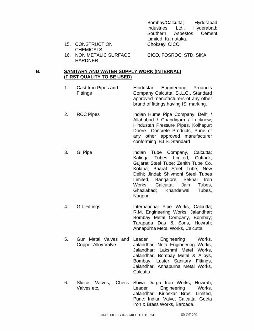
CHAPTER : CIVIL & ARCHITECTURAL 60 OF 292
Bombay/Calcutta; Hyderabad Industries Ltd., Hyderabad; Southern Asbestos Cement Limited, Karnataka.
15. CONSTRUCTION CHEMICALS
Choksey, CICO
16. NON METALIC SURFACE HARDNER
CICO, FOSROC, STD, SIKA
B. SANITARY AND WATER SUPPLY WORK (INTERNAL)
(FIRST QUALITY TO BE USED)
1. Cast Iron Pipes and Fittings
Hindustan Engineering Products Company Calcutta, S..L.C., Standard approved manufacturers of any other brand of fittings having ISI marking.
2. RCC Pipes Indian Hume Pipe Company, Delhi /
Allahabad / Chandigarh / Lucknow; Hindustan Pressure Pipes, Kolhapur; Dhere Concrete Products, Pune or any other approved manufacturer conforming B.I.S. Standard
3. GI Pipe Indian Tube Company, Calcutta;
Kalinga Tubes Limited, Cuttack; Gujarat Steel Tube; Zenith Tube Co. Kolaba; Bharat Steel Tube, New Delhi; Jindal; Shivmoni Steel Tubes Limited, Bangalore; Sekhar Iron Works, Calcutta; Jain Tubes, Ghaziabad; Khandelwal Tubes, Nagpur.
4. G.I. Fittings International Pipe Works, Calcutta;
R.M. Engineering Works, Jalandhar; Bombay Metal Company, Bombay; Tarapada Das & Sons, Howrah; Annapurna Metal Works, Calcutta.
5. Gun Metal Valves and
Copper Alloy Valve Leader Engineering Works, Jalandhar; Neta Engineering Works, Jalandhar; Lakshmi Metel Works, Jalandhar; Bombay Metal & Alloys, Bombay; Luster Sanitary Fittings, Jalandhar; Annapurna Metal Works, Calcutta.
6. Sluice Valves, Check
Valves etc. Shiva Durga Iron Works, Howrah; Leader Engineering Works, Jalandhar; Kirloskar Bros. Limited, Pune; Indian Valve, Calcutta; Geeta Iron & Brass Works, Baroada.

CHAPTER : CIVIL & ARCHITECTURAL 61 OF 292
7. Brass Fittings Leader Engineering Works,
Jalandhar; L & K Mathura; Luster Sanitary, Jalandhar; Annapurna Metal Works, Calcutta; Neta Metal Works, Jalandhar; Honey Industrial Corporation, Bombay.
8. C.P. Fittings Ego Metal Works, Ballabhgarh;
Jaquar Industries, Delhi; Soma Plumbing Fixtures Limited, Calcutta; Gem Sanitary Appliances Pvt. Ltd.,Delhi; Essco Sanitations, Delhi; Bilmet, Bombay.
9. W.C. Pan Wash Basin,
Urinals, Sink Low down Flushing Cistern
E.I.D. Parrys, Madras, Hindustan Sanitaryware, Calcutta; Neiveli Ceramics, Tamil Nadu; Cera Ceramics.
10. E.W.C. Seats Nuchem Plastics Limited, Faridabad;
Commander, Bombay; Bestolite Jasco Sales, Bombay; Agarwala Products, Bombay.
11. Flushing Cistern Arail Brothers, Delhi; Allied Industries,
Jaipur; Fordham Pressing (India) Pvt. Limited, Bombay; Klassik Enamellers, Bombay; Sushila Industries, Sundergarh; Small Machine Tools Company, Howrah; Thakurdass Surekha Engg. Corporation Pvt. Ltd., Calcutta; E.I.D. Parry (India) Pvt. Ltd., Madras; Hindustan Sanitaryware & Industries Ltd., New Delhi; Neiveli Ceramics and Refractories Limited, Tamil Nadu.
12. Hydrants Brady's, Bombay; Firex, Bombay;
Upadhya Valves, Calcutta; Eddy Foundry, Calcutta, Minimax.
13. Mirrors Atul Glass Works, Vallabh Glass
Works, Goldenfish 14. White Glazed Tiles H & R Johnson TilesCompany,
Bombay; Somani Pilkingtons Co., Haryana
15. Asbestos Cement Pipes
and Fittings Ganga Asbestos Limited, U.P.; Hyderabad Asbestos Cement Products Limited; J.K. Super Pipe Industries, Nanded; Konark Cement

CHAPTER : CIVIL & ARCHITECTURAL 62 OF 292
and Asbestos Limited, Orissa; Maharashtra Asbestos Limited, Bombay; Poddar Industrial Corporation, Patna; Sarbamangala Mfg. Company, Calcutta
16. Stone Ware
(Salt-Glazed) Pipes Hind Ceramics Limited, Orissa; Ceramic Industries Limited, Sambalpur; Shrikamakshi Agencies, Madras; Binary Udyog Pvt. Limited, Howrah; Tirumati Moulds Limited, Nagpur; Kiran Potteries, Hyderabad; Perfect Sanitary Pipes, Bharatpur.
23.0 MATERIALS NOT SPECIFIED Any materials not fully specified in these specification and which may be
offered for use in the works shall be subject to approval of Engineer, without which it shall not be used anywhere in the construction works.
CHAPTER : CIVIL & ARCHITECTURAL 63 OF 292
SPECIFICATION FOR CIVIL & ARCHITECTURAL WORKS: PART II :
WORKMANSHIP 1.0 GENERAL 1.1 Standard
A high standard of workmanship in all trades will be required. The Contractor shall ensure that only skilled and experienced workmen are employed.
1.2 Supervision
The Contractor's supervising staff shall be fully qualified and experienced in the types of work being carried out under their supervision and shall be capable of ensuring that work is executed efficiently and as per specification.
1.3 Temporary works
Where required, the Contractor shall furnish such details of his temporary works as may be called for by the Engineer and the Contractor shall satisfy the Engineer as to their safety and efficiency. The Engineer may direct that temporary works, which he considers unsafe or insufficient, shall be removed and replaced in a satisfactory manner.
1.4.0 Codes 1.4.1 The years of publication against various standards, referred in this
specification, correspond to the latest standards as on date of preparation of this specification. During use of this specification in future, the latest publication as on date shall be referred to. Where standards are not yet published by the BIS or IRC, adoptable British Standards or other International Standards shall apply.
In case of any conflict in meaning between these specifications and those
of BIS or IRC, or British/International Standards, the provisions of these specifications shall prevail.
1.5 Base lines and bench marks The Contractor shall establish and maintain, to the satisfaction of Engineer,
the base lines and bench marks, based on which the works are set out. Where such base lines and bench marks are provided by the Engineer, the Contractor shall maintain these throughout the period of construction without causing any disturbance to them.
1.6 Setting out The Contractor shall set out all the works to be executed by him, in line
with the standard base lines, levels, position and bench marks and truly as
CHAPTER : CIVIL & ARCHITECTURAL 64 OF 292
per drawings within the accepted tolerance limits at no extra cost to Owner. The Contractor shall be solely responsible for the setting out of all the works, to be executed by him and the approval of such setting out by the Engineer shall in no way absolve the Contractor his responsibility for carrying the work to the true lines, levels and positions as per drawings.
1.7 Dewatering The Contractor shall carry out all the works, in dry and workable condition
and maintain the same in dry condition till the final handing over of works at no extra cost to the Owner. For this the Contractor shall make all the necessary provisions of dewatering, wherever necessary, to the entire satisfaction of the Engineer.
1.8 Safety of existing work Before taking up any construction adjoining other property or existing work,
the Contractor shall take all steps necessary for the safety and protection of such property or work at no extra cost to the owner.
1.9 Protection of existing services The Contractor shall take all precautions necessary to prevent damage to
or interference with underground or over ground services such as cables, drains, piping or piles, whether shown on drawings or not. Equipment etc., mounted in position shall be protected against falling debris etc., by means of tarpaulin or such other material at no extra cost to the owner.
1.10 Handing over of work site On completion of work, the Contractor shall remove all rubbish, debris,
surplus materials, temporary work etc., from the site. The site shall be handed over in a tidy and workmanlike manner at no extra cost to the owner.
2.0 EARTH WORK 2.1 Scope This chapter deals with earth work and excavation for civil works in site,
formation / over site leveling, foundations, cutting and grading for roads/pavement and railways, canals, embankments other than water retaining embankments trenching for drainage and other burried services and the like.
2.2 General The Contractor shall carry out the excavation strictly to the lines and levels,
in conformity with the drawings or instructions of the Engineer. 2.3 Setting out

CHAPTER : CIVIL & ARCHITECTURAL 65 OF 292
Before commencement of earthwork block levels of existing ground shall be
taken by the Contractor jointly with the Engineer, plotted and signed in token of acceptance of ground levels. Excavation shall not be commenced until the initial ground levels have been recorded and accepted. Reference lines, bench marks and base lines shall be set out by the Contractor for control of earthwork operation. Setting out shall be done with pegs, blocks, bamboo poles or rails, marking boundaries or centre lines, as the case may be, and the same maintained for reference and future checking. Chainaie stones at regular intervals shall be set up for embankments. All setting out operations shall be got checked and approved by Engineer. However, such checking and approval by the Engineer shall in no way absolve the Contractor of his responsibilities for carrying out the work to the true lines, levels and positions as per drawing, and in case any error is noticed at any stage in the contractor's work, it shall be corrected/rectified by him without any cost to the Owner.
2.4 Site clearance and demolition The site shall be cleared of all trees, stumps, roots, brush wood, bushes
and other objectionable materials. Useful and saleable material, if any, shall be the property of the owner and shall be stacked properly as directed by the Engineer. The areas to be covered with embankments shall be stripped of top soil to required depths to expose acceptable founding strata. Top soil unsuitable for use in embankment construction and other fills shall be disposed off as directed. All combustible materials shall be stacked and burnt in locations sufficiently remote to eliminate all danger of fire hazards. All old concrete, brick works and drains which interfere with construction works shall be dismantled with the approval of the Engineer taking all necessary precautions prescribed in safety specification. Top soil which is suitable for use in construction work shall be stockpiled for later use. Other objectionable materials such as trash, debris, stones, brick, broken concrete, scrap metal etc., shall be disposed off as directed by the Engineer. Payment for cutting and removal of trees, stumps, dismantling existing structures and stripping shall be regulated by the description in the Schedule of Items or Part V of these specifications.

CHAPTER : CIVIL & ARCHITECTURAL 66 OF 292
2.5 Classification of soil The Engineer will decide the class of any particular soil. Classification of
soil shall be as under and the decision of the Engineer shall be binding on the Contractor :
A) Ordinary Soil
Soils which yield to ordinary application of pick and shovel, phawra rake or other ordinary digging implements (including earth moving equipment such as bulldozer, shovels without resorting to blasting) without offering much resistance, shall be classified as ordinary soil. This includes organic soil, turf, sand, gravel, loam clay, mud, peat, black cotton soil, soft shale and loose moorum etc.
B) Hard Soil
This comprises of all soils that cannot reasonably be excavated by the above mentioned digging implements, but can be excavated with close application of pick axe or scarifiers or jumpers to loosen. This includes compact moorum, stiff clay, hard shale, cobble stone etc.,
C) Soft /Decomposed Rock
This comprises of rock or boulders which may be quarried or split with crow bars, pavement breakers etc. This include lime stone, sand stone, weathered rocks and hard conglomerates etc. and existing structures embedded in earth and tarred macadam roads, pavements, met in the excavation. The fact that contractor resorts to blasting for his own reasons shall not mean that the rock is hard and classified as hard rock.
D) Hard Rock
This comprises of rocks which require blasting for excavation. Where blasting is prohibited, excavation has to be carried out by chiseling, wedging or any other agreed methods.
2.6 Method of excavation The Contractor may carry out excavations, filling and compaction by any
method considered most suitable, and befitting the site conditions subject to any stipulations contained in the contract and the specifications. All excavations shall be required to be kept completely free from water, from whatever source it may come, during the construction. No foundation work shall be taken up until the surfaces are properly drained.
2.7 Excavation of soils other than hard rock Excavation shall be carried out in the most expeditious and efficient manner
to the lines and levels as indicated in drawings or as directed by Engineer. Prior approval of the Engineer shall be taken for the method to be adopted
CHAPTER : CIVIL & ARCHITECTURAL 67 OF 292
for excavation including dimensions, side slopes, dewatering, shoring etc., Such approval shall not make the Engineer responsible for any consequent damage or loss caused. All precautions shall be taken to preserve the material below and beyond line of excavation in soundest condition. All damages done beyond limits of excavation shall be made good by the Contractor at his own cost in a manner approved by the Engineer. All excavated materials shall be removed to spoil heaps, dumping yards or transported for filling as may be necessary. When soil heaps are formed for future use, heaps shall be protected from washing away due to rain or surface run off. The sides of excavation shall be maintained in stable condition by adequate stepping and batter. To prevent entry of surface water and accumulation of subsoil water in excavated areas, suitable drainage arrangements as may be needed and directed by Engineer, shall be provided and maintained. Pumped out water shall be drained off properly avoiding damage to other existing works. If any pipelines, cables or service lines are likely to be exposed, excavation around these services shall be carried out manually and all such services shall be adequately supported and protected at no extra cost.
Excavation shall be carried out in any material encountered including road
surfaces, pavements, burried parts of old foundations, pits or other structures. Excavated materials shall be placed beyond 1.5 metres of the edge of the excavation pit/trench or half the depth of the pit/trench whichever is more or further away as directed by the Engineer. Sumps made for dewatering must be kept clear of the foundations.
In firm soil the sides of the trenches shall be kept vertical upto a depth of
2.0m from the bottom and for a greater depth, trench shall be widened by allowing steps of 50cm on either side after every 2.0m depth from the bottom, so as to give a vertical side slope of 1/4 : 1. Where the soil is soft, loose or slushy, the width of the steps shall be suitably increased or sides suitably sloped or suitable shoring and strutting provided as directed by the Engineer. For trenches deeper than 2.0m, the Contractor shall obtain detailed instruction from the Engineer in writing regarding the stepping, sloping of sides or shoring and strutting to be done. For these bye-works, no extra cost will be paid to the Contractor.
2.8 Excavation in hard rock Where hard rock is met and blasting is considered necessary for its
excavation, the Contractor shall intimate the Engineer in writing. Excavation in hard rock shall be done either by blasting or chiseling or by such other agreed methods as may be required. Levels of hard rock surface shall be taken and got approved by Engineer before start of excavation. Blasting shall be permitted only when proper precautions are taken for protection of persons, works and property. The Contractor shall obtain the necessary licence for procuring, storing and using explosives.
Blasting operations shall be carried out by a licensed Blaster. The quality
and quantity of explosives, size and spacing of holes depth of holes etc., shall be such that they will neither open seams nor damage or shatter the rock beyond the specified lines of excavation. A tolerance of 150 mm will however be allowed beyond the excavation lines. As excavation

CHAPTER : CIVIL & ARCHITECTURAL 68 OF 292
approaches final stages, the depth of holes and the amount of explosives used shall be reduced progressively to avoid over breakage or damage to founding strata. Any fissures, cracks and voids below prescribed depth of excavation shall be corrected by removing loose pieces, shattered or affected rock and replaced by lean concrete of M-5 grade or (1:5:10) cement concrete in the case of foundations. Where excavated surface is to receive structural concrete, the surface shall be cleaned of dust and other objectionable materials.
In cases where blasting, though otherwise required, is prohibited because
of any reason, the excavation shall be carried out by chiseling, wedging or such other agreed methods. All materials excavated from blasting, chiseling or any such methods shall be stacked for measurement as directed by Engineer.
2.9 Cutting and filling for site leveling Excavation and filling operations for site leveling shall be so planned and
executed, that transportation and re-handling are minimised. The sides of excavation and fills shall be maintained in stable condition by adequate batters, stepping and dewatering. Materials not desirable shall be disposed off in area indicated by Engineer. When it is required to blend the material, it shall be done by selective excavation and filling operation. Wells, ponds, cesspools and water logged areas shall be emptied of water and deslushed before filling. Filling shall be done in horizontal layers not exceeding 300mm in thickness as specified or as directed by the Engineer. All clods shall be broken before placing the fill. Earth moving equipment shall be allowed to ply over the fill to permit compaction. Adequate allowance shall be made for subsidence of fill material. Levels shall be taken and excess or shortfall shall be made good by appropriate cutting or filling.
CHAPTER : CIVIL & ARCHITECTURAL 69 OF 292
2.10 Excavation for trenches Excavation for trenches shall be carried out in materials encountered to
enable laying of service lines or drainage channels or any other desired purpose. Excavation shall be done to lines and levels shown in drawings and shall be done providing adequate measures for stability. Vertical wooden sleepers or light rails shall be erected at uniform levels at places where changes of direction and gradients occur. Centre lines shall be marked on horizontal sleepers or rails, laid across the trenches. Depths of excavation and pipe invert levels shall be checked by means of boning rods of appropriate lengths. Trench beds shall be trimmed and rammed with sprinkling of sand or moorum to required gradients for continuously supporting the pipelines. Trenches shall be locally deepened and widened to receive sockets and permit joints to be inspected.
Timbering In case of trenches, tunnels, channels, drains, manholes, chambers,
basement and other places where the soil is not capable of being retained without the support, timbering as directed by the Engineer shall be resorted to. It shall be the responsibility of the Contractor to take all the necessary steps to prevent the sides from collapsing.
2.11 Excavations for foundations Excavation for foundation shall be done to the lines and levels indicated in
the drawings. Excavated material shall be transported and stored at convenient spots for reuse in back filling of foundations and other fills. Surplus material shall be transported, spread and levelled at dumping areas. Side slopes of excavation and/or shoring shall be adequate from consideration of stability and working space. When so required and authorised by Engineer, the sides of excavation shall be protected with proper shoring, strutting, sheeting and sand bags etc., These shall be removed only when work in the pit is completed, with the approval of the Engineer. When it is felt that removal of supports may result in side collapse or settlement of adjoining ground or endanger adjoining structures and foundations, they shall be left permanently in position. The last 150 mm of excavation shall be done and the bottom trimmed to the required levels only when concreting is imminent. If at any point the natural ground is disturbed or loosened for any reason, it shall be consolidated by tamping or rolling or made up with concrete of M-5 grade, or (1:5:10) cement concrete if so ordered by the Engineer at no extra cost. Where the soil encountered at depths indicated in drawings is loose or weak, it shall be further excavated to levels of firm strata as may be directed by the Engineer and filled with lean concrete of M-5 grade/(1:5:10) cement concrete or sand as directed. If the bottom of excavation has been left exposed not through neglect or fault of the Contractor and it has become deleteriously affected by atmospheric action and water, such portion of deteriorated foundation material shall be removed and made good by lean concrete of grade M-5/(1:5:10) cement concrete or sand as directed and such extras will be paid for.

CHAPTER : CIVIL & ARCHITECTURAL 70 OF 292
2.11.1 For deep excavation in the proximity of existing buildings, foundations,
streets, railway tracks, underground cabling, gas piping, water and drainage lines, and the like, adequate appropriate precautions shall be taken to protect such structures or works from damage, displacement or settlement, either as an immediate result of the excavation or as after effect, discernible with the passage of time. The method of protection of existing structures and services may include sheet piling, shoring, strutting slinging or any other method including dewatering. Payment for such protective work shall be governed by the description given in the Schedule of Items for the particular work.
2.11.2 For excavation adjoining existing piles care shall be taken to ensure that no
pile under any circumstances is exposed from the top for a height exceeding 2 metres. No strutting shall be done against exposed piles, nor exposed piles ever used for tying guy ropes or supports either temporarily or permanently.
2.12 Excess excavation All excavation done beyond the specified limits or directions of Engineer
shall be considered as excess excavation. They shall be made good as prescribed below by the Contractor at his cost:
i) Excess excavation in case of site leveling shall be made good by
filling and compacting with material same as the surrounding material. Degree of compaction shall be at least the same as the surrounding material.
ii) Excess excavation in case of trenches shall be made good by filling
and compacting with selected earth to the same compaction as the surrounding material or as directed by Engineer. This shall be done in layers not exceeding 150 mm thick, moistened and thoroughly compacted by tamping.
iii) Excess excavation in case of foundation beyond required depths
shall be made good by filling with lean concrete of M-5 grade/(1:5:10) cement concrete.
CHAPTER : CIVIL & ARCHITECTURAL 71 OF 292
2.13 Disposal of excavated materials Excavated materials that are unsuitable for use in construction works or in
excess of construction requirements shall be disposed off in dumping yards or in locations indicated by Engineer. Waste piles/heaps shall be located in such places where they will not interfere with natural flow of rain water access or transport or with the access to nearby structures. When required, they shall be levelled and trimmed to such lines and levels as indicated by Engineer.
2.14 Back filling of trenches Trenches shall be backfilled after pipes or service lines are tested and
approved. Filling shall be done with earth in 150 mm thick layers free from unwanted material and well rammed. Soft material shall be used in bottom of trenches upto a level of 150 mm above the top of pipes before backfilling with other fill materials. All clods and lumps shall be broken before placement. Care shall be taken not to disturb, break or damage the pipes during backfilling and compaction process.
2.15 Backfilling of foundations Backfilling of foundations shall be done using suitable soils from
excavations. Soil shall be free from organic matter and other materials which would affect the stability of the fill and shall be free from boulders, brick bats wood pieces and other injurious materials, lumps and clods. Before commencement of backfilling of foundations. all shoring and formwork, bits of timber, cement bags and all other rubbish shall be removed. Hydro-insulation, Bitumen painting or application of anti-corrosive protective and anti-termite treatments shall have been completed. Backfilling operation shall not commence without approval of Engineer. Backfilling shall be carried out in well compacted layers of 150 mm thickness. Each layers shall have near optimum moisture content. Layers will extend to the entire width of excavation and shall be sprinkled with water during compaction process. Ramming shall be done to achieve firm compaction. Backfill shall be trimmed and finished to lines and levels indicated in the drawings and/or as directed by the Engineer. Mechanical equipment like vibratory roller, vibro earth rammer or vibratory compactor shall be used for compaction.
2.16 Filling under floors Material for filling under floors shall be soil free from harmful minerals,
vegetable matter etc., and shall not be expansive soils. Filling shall be done in well compacted layers not exceeding 150 mm in thickness. Each layer shall be compacted to 95% Standard Procter Density. Sufficient soaking shall be done before compaction. The entire area to be covered by flooring shall be finally dressed and trimmed to required levels. Mechanical equipment like vibratory roller, vibro earth rammer or vibratory compactor shall be used for compaction.
2.17 Load bearing fills

CHAPTER : CIVIL & ARCHITECTURAL 72 OF 292
Load bearing fills include embankments for roads and railways and such
other earth fills above ground levels provided for protection of fuel oil tanks, pads for storage tanks, drain, bunds and the like. Fill materials shall either be selected earth obtained from excavations for site leveling, trenches and foundations or from selected borrow areas as may be required. Soils selected for filling in embankments shall be of uniform quality and free from boulders, organic materials and other objectionable matter. Soils having high silt and clay content and having laboratory maximum dry density less than 1.44 gms per c.c. shall not be used for load bearing fills. For fills greater than 3 m in height soils shall have laboratory density not less than 1.52 gms per c.c. Soils for top 500 mm of fills for roads and railways shall have laboratory density not less than 1.65 gms per c.c. and shall not have marked swelling and shrinkage properties.
Foundation preparation for embankments shall be done as prescribed
under site clearance. The founding strata shall be compacted as much as possible by rolling or tamping before placement of fill material. The water content of founding strata should be same as that specified for embankment fill. Any pockets of loose material or depressions left in founding strata as a result of clearing operation shall be filled and compacted with the same material as the surrounding founding strata. When an embankment is to be placed on steep sloping ground the surface of the ground shall be trenched in steps or trenched or broken up in such a manner that the new materials bonds well with the founding strata.
Fill material shall not be placed until foundation has been inspected and
approved by Engineer. Material shall be placed in even, continuous, horizontal layers over full width of embankment in well compacted layers not exceeding 200 mm thickness. Each layer shall be compacted by means of smooth rubber tyred rollers, sheep-foot rollers, tractors, tampers or other mechanical means as may be found suitable for the location. Before rolling, the water content shall be checked and corrected by sprinkling with water or adding dry material or aeration as may be required. This shall be followed by mixing and the layer left for soaking before compaction. The water content shall be within plus or minus 2% of Standard Proctor Optimum. Density of compacted layers shall be determined by sand replacement method. Average compacted density shall be at least 95% of Standard Proctor Density. The number of tests to be conducted for determination of moisture content and density shall be as prescribed by the Engineer. Side slopes of embankments shall be formed along with the main embankment. No side dumping shall be done for the formation of slopes. When required the width of each layer shall be constructed slightly in excess of required width and slopes trimmed to remove loose edge materials and completed to lines shown in drawings or as directed by the Engineer. Subgrades for road works shall be thoroughly wetted sufficiently in advance of placing of any base course and it shall be ensured that it is firm and moist for at least 50 mm below the surface. Should the subgrade for any reason be loose or have density less than required, it shall be recompacted and refinished. Excessive loss of moisture in the subgrade shall be prevented by sprinkling and/or scaling. No traffic or hauling equipment shall be permitted to ply on finished

CHAPTER : CIVIL & ARCHITECTURAL 73 OF 292
subgrade and any damage caused to such portion shall be made good by the Contractor at his own cost.
2.18 Turfing The slopes of embankment shall be dressed to line and slightly roughened
to bond and hold a surface dressing consisting of 150 mm humus layer of soil. The entire surface shall then be covered with turf consisting of blocks or strips of grass of approved species. The sod shall include a net of roots and earth at least 75 mm thick. The sod shall be laid on slope in close contact and then tamped in place so as to close and fill the joints between blocks.
Immediately after placing the turf, slope shall be thoroughly wetted and
kept wet for a sufficient period to assure plant growth. Watering shall be continued until the grass takes root firmly and the whole area presents a uniform appearance. In the event that the plant growth has not taken place within the period of maintenance such areas or patches shall be redone by the Contractor at his own cost.
3.0 ANTI-TERMITE TREATMENT 3.1 Scope The scope of work includes setting up a chemical barrier against attack by
subterranean termites while the building is under construction. 3.2 Execution 3.2.1 General Unless otherwise specified all work shall in general be executed as
specified in IS : 6313 Part-II -1981 and as per approved specification of the agency having special know-how for the job.
All necessary work to ensure uniform distribution and proper penetration of
treating solution shall be done according to the instruction of the Engineer. Soil treatment shall not be done when it is raining or when the soil is wet
with rain or subsoil water. Once formed, the treated soil barrier shall not be disturbed.
3.2.2 Chemicals and rate of application Chemical like chlorpyriphos 20% EC (Conforming to IS 8963 - 1978) in 1%
emulsion shall be applied by pressure pumps, uniformly over the area treated. (1 part chemicals + 20 parts water = 1% emulsion).
3.2.2.1 Treatment of pits, trenches & basement excavations Foundations, basements etc. may either be fully enveloped by the chemical
barrier or the treatment may start 500 mm below ground level. The bottom
CHAPTER : CIVIL & ARCHITECTURAL 74 OF 292
surface and sides of excavation (upto a height of about 300mm) for column pits, walls, trenches and basements shall be treated with emulsion @ 5 liters per sq.m. of surface area. Backfills around columns, walls, etc., shall be treated @ 7.5 liters per sq.m. of the vertical surface. Treatment shall be done in stages following the compaction of earth in layers. The treatment shall be carried out after the ramming operation is done by rodding the earth at 150mm centers closed to the wall surface and spraying the emulsion in the specified dose.
3.2.2.2 Treatment of top surface of plinth filling Holes 50 mm to 75 mm deep at 150 mm centres both ways shall be made
with crow-bars on the surface of compacted plinth fill. Emulsion at the rate of 5 litres per sq.m of surface shall be applied prior to laying soling or subgrade. Special care shall be taken to maintain continuity of the chemical barrier at the junction of vertical and horizontal surfaces.
3.2.2.3 Treatment of doors, windows & soil surrounding pipes, Wastes and
conduits. Special care shall be taken at the points where pipes and conduits enter
the building and the soil shall be treated for a distance of 150 mm and a depth of 75 mm at the point where they enter the building. All the wooden door/window frames on the ground floor of the buildings shall be treated with the insecticidal solution.
3.2.2.4 Treatment of expansion joints These shall receive special attention and shall be treated in a manner
approved by the Engineer. 3.3 Acceptance Criteria The Contractor shall give a 10 year service guarantee in writing
supplemented by a separate and unilateral guarantee from the specialised agency for the job to keep the building free of termites for the specified period at no extra cost to the Owner.
4.0 CONCRETE PLAIN & REINFORCED 4.1 Scope This chapter covers the workmanship, special requirements & regulations
with which the contractor must comply to achieve the following two objectives :
(a) The provision, at all locations on the site, of dense workable
concrete, having the specified characteristic strength.
(b) The placing of concrete at all elevations, well compacted by vibrations, in well aligned and well fixed formwork ensuring the internal and external dimensions of structures as per drawings and maintaining the size, shape number and locations of reinforcements,

CHAPTER : CIVIL & ARCHITECTURAL 75 OF 292
inserts etc., as specified in the drawings providing the surface finish after stripping off the formwork to ensure the structural configurations as per drawings as well within the specified tolerance limits, curing and guaranteeing the characteristic strength, all as specified.
4.1.1 The mixing, placing, compacting, curing and finishing of concrete shall be
done according to IS: 456-1978 "Code of Practice for Plain and Reinforced Concrete".
4.2 Materials For materials, reference to Part - I (Materials) shall be made. 4.3 Grades of Concrete The grades of concrete unless otherwise specified shall be in accordance
with the following table. The grade of concrete to be used in each section of work will be shown in the drawings or in the schedule of items :

CHAPTER : CIVIL & ARCHITECTURAL 76 OF 292
Grade off Concrete
Characteristic Strength i.e. Compressive Strength of 15 cm cubes at 28 days
(N/mm2
Nominal Maximum Aggregate Size (mm)
M-5A 5 63
M-5B 5 40
M-7.5A 7.5 63
M-7.5B 7.5 40
M-10A 10 63
M-10B 10 40
M-10C 10 20
M-10D 10 12
M-15A 15 63
M-15B 15 40
M-15C 15 20
M-15D 15 12
M-20A 20 63
M-20B 20 40
M-20C 20 20
M-20D 20 12
M-25C 25 20
M-25D 25 12
M-30C 30 20
M-30D 30 12
M-35C 35 20
M-35D 35 12
M-40C 40 20
M-40D 40 12

CHAPTER : CIVIL & ARCHITECTURAL 77 OF 292
Notes : A,B,C,D mentioned along with grade of concrete correspond to the maximum size of coarse aggregate being 63mm, 40mm, 20mm & 12mm respectively.
Unless otherwise specified in the drawings or schedule of items the
maximum nominal size of coarse aggregates for different grades of concrete shall be as under : a) For concreting in very narrow space or in very small
thickness 12 mm
b) For all reinforced concrete work except in massive foundations
20 mm
c) For all ordinary plain concrete & massive reinforced foundations
40 mm & 63 mm
4.4 Mix Design 4.4.1 General At the commencement of the contract the Contractor shall make preliminary
tests to determine the proportions by weight of cement, fine aggregates, coarse aggregates and water necessary to produce required grades of concrete. The mix proportions shall be selected to ensure that workability of the fresh concrete is suitable for the conditions of handling and placing and when concrete hardens, it shall have the required strength, durability and surface finish. The Contractor shall get approval of Engineer to such proportions before he starts concreting. However, such approval shall not relieve the Contractor of his responsibility to produce concrete having compressive strengths as laid down in the foregoing Table.
No departure from the approved proportions will be permitted during the
works unless and until the Engineer gives written authorisation for any change in proportion. The Engineer shall have authority at any time to check whether the mixing of concrete is being carried out according to the approved proportions.
4.4.2 For the all major and important R.C. works and for all special works, the
design of mixes shall be made by the Contractor at his own cost, for each grade of concrete as well as for various workability. The design of mixes shall be made according to I.S. 10262-1982 or any other approved standard methods.
4.4.3 The concrete made by designing the mix is termed hereinafter as "Design
Mix Concrete". 4.4.4 The cement content for various grades of concrete shall be based on
design mix. However, irrespective of requirement of cement found out from design mix, the minimum cement content & maximum cement content of concrete shall be in accordance with Clause No. 8.2.4.1 & Clause No. 8.2.4.2 of I S 456 -2000 respectively.
4.5 Water/Cement Ratio

CHAPTER : CIVIL & ARCHITECTURAL 78 OF 292
4.5.1 Where a particular water/cement ratio is stipulated in the design or drawing
along with the characteristic grade of concrete the design of mix shall be carried out by adjusting the other variable factors to obtain the characteristic strength of concrete with stipulated water/cement ratio.
4.5.2 In the structures where the impermeability and shrinkage of concrete have
an important bearing on the durability and serviceability of the structures, such as water retaining structures, basements, underground premises, tunnels, pump houses, exposed structures near sea side or deserts, prestressed structure, thin precast members etc. the water cement ratio shall be kept low and preferably not exceeding 0.45.
4.5.3 The water cement ratio, as achieved in the Mix Design, or as specified in
the drawings shall be adhered to strictly and shall not be varied without the permission of the Engineer.
4.6 Workability 4.6.1 The workability of fresh concrete shall be such that the concrete is just
suitable for the conditions of handling & placing so that after compaction if becomes completely consistent and homogeneously surrounds all the reinforcement and completely fills the formwork.
4.6.2 The workability of fresh concrete at the place of batching/mixing shall be
measured by compacting factor test and at the place of disposition by means of slump test. During the finalisation of Trial Mixes, the relationship between compacting factor and slump test shall be established for each grade of concrete as well as for various levels of workability. The workability tests shall be carried out in accordance with IS:1199-1959.
4.6.3 Normally, in the condition of low water cement ratio as well as for
medium/high workability, the workability shall be achieved by increasing the cement content, in consistent with added water.
4.6.4 In cases where the cement content is to be limited to reduce the heat of
hydration, and the water/cement ratio is also to be kept low to reduce the permeability or due to other requirements the desired workability may be achieved with use of limited doses of plasticiser or air entraining agent. In such cases the method of mixing and dosage of the plasticiser/air entraining agent shall be according to the manufacturer's specification and with the approval of the Engineer.
4.6.5 The usual limits of consistency for various types of structures are given
below :
Limits of consistency
Slump in mm with Standard - Cone
Degree of Workability
Minimum Maximum
Use for which concrete is suitable as per IS : 1199
Very low 0.0 25.0 Large mass concrete structure with heavy

CHAPTER : CIVIL & ARCHITECTURAL 79 OF 292
compaction equipment, roads and the like.
Low 25.0 50.0 Uncongested wide and shallow R.C.C structures
Medium 25.0 75.0 Deep but wide R.C.C
structures with congestion of reinforcement and inserts
High 75.0 125.0 Very narrow and deep R.C.C
structures with congestion due to reinforcement and inserts
Note : Not withstanding any thing mentioned above, the slump to be obtained for
work in progress shall be as per direction of the Engineer. With the permission of the Engineer, for any grade of concrete, if the water has to be increased in special cases, cement shall also be increased proportionately to keep the ratio of water to cement same as adopted in trial mix design for each grade of concrete. No extra payment will be made for this additional cement.
CHAPTER : CIVIL & ARCHITECTURAL 80 OF 292
4.7 Durability The durability of concrete, depending on the exposure condition, is to be
taken into account while designing the mix. For given aggregates, the cement content should be sufficient to make sufficiently low water cement ratio and Appendix A of IS: 456-1978 shall be taken as guideline for durability considerations.
4.8 Trial Mixes 4.8.1 After approval of the Mix Design by the Engineer, the Contractor shall make
in presence of Engineer the Trial Mixes for each grade of concrete as well as for required workability.
4.8.2 Before starting the trial mixes, necessary preparatory works like sieve
analysis of the aggregates, determination of densities of different ingredients and moisture contents in the aggregates, shall be completed according to the I.S. Codes 383-1970 and 2386-1963.
4.8.3 Each trial mix shall be handled and compacted by the method which the
Contractor proposes to use for that mix in the works and the mixes shall not show tendency of inadequate compaction by the method proposed.
4.8.4 The compacting factor and the slump of each trial mix shall be determined
immediately after mixing and the values shall not exceed the maximum value obtained in the mix design.
4.8.5 Six numbers of 150 mm test cubes shall be made from each trial mix.
These shall be cured and tested in accordance with relevant I.S. codes. In order to have the specified characteristic strength in the field, the concrete mix as designed in the Design Mix shall have higher average compressive strength depending on the degree of quality control at site. If the size and special requirement of the work so warrants, the trial may be extended to cover larger ranges of mix proportions as well as other variables such as alternative source of aggregates, maximum size and grading of aggregates and different type and brands of cement.
4.8.6 Before commencement of the concreting works of particular grade of
concrete, the Contractor must complete the work of trial mixes and subsequent testing of the test cubes obtained therefrom the design of the Approved Mix for that particular grade of concrete.
4.8.7 The entire cost of all the trial mixes including all the preparatory works for
trial mixes, preparation of test cubes and their testing shall be borne by the Contractor.
4.9 Nominal Mix Concrete 4.9.1 Nominal mix concrete may be used for all concrete of Grade M-10 and
below. If design mix concrete cannot be used for any reason for Grade M-15 & M-20, nominal mix concrete may be used with the permission of
CHAPTER : CIVIL & ARCHITECTURAL 81 OF 292
Engineer, Nominal mix concrete shall not be used, in any case for Grade of concrete above M-20.
4.9.2 The proportioning of materials for nominal mix concrete shall be in
accordance with Table-3 of clause 8.3 of I.S. 456-1978. The stipulations of Clauses 8.3.1 & 8.3.2 of IS: 456-1978 shall also be taken into consideration.
4.10 Volumetric Mix Concrete Where concrete is specified in volumetric proportions such as 1:4:8, 1:3:6,
1:2:4, 1:1 1/2:3, 1:1:2 etc., in the schedule of items, coarse and fine aggregates shall be measured by volume and cement by weight. The water cement ratio shall be within 0.45 to 0.70 depending upon the workability.
4.11 Batching of Concrete 4.11.1 Cement Cement shall always be batched by weight. A separate weighing device
shall be provided for weighing cement. Where the weight of cement is determined by accepting the weight per bag, number of bags shall be weighed separately to determine the average net weight of cement per bag and the same shall be checked regularly
4.11.2 Aggregates 4.11.3 For both Design Mix concrete and Nominal Mix concrete, the aggregates
(coarse and fine) shall be batched by weight. 4.11.4 In particular cases, or where weigh-batching is not possible proportioning
by volume batching may be allowed by the Engineer, provided the Contractor guarantees the uniformity of aggregates through out the period of construction. For this purpose, the Contractor shall submit to the Engineer sufficient data indicating the weight/volume relationship of aggregates for different types of concrete and after such approval, periodic checks on the weight/volume relationship of the aggregates shall be made by the Contractor to the satisfaction of the Engineer. Where aggregates are moist and volume batching is adopted, allowance shall be made for bulking in accordance with I.S. 2386 (Part-III)-1963.
4.11.5 Suitable adjustments shall be made for the variation in the weight of
aggregates due to variation in their moisture contents. 4.12 Water 4.12.1 Water may be measured either by weight or by volume. When measured
by volume, it shall be by well calibrated conical shaped jar or vessel or from a calibrated tank fitted to the mixer.
4.12.2 Adjustment of water due to moisture contents in coarse and fine
aggregates
CHAPTER : CIVIL & ARCHITECTURAL 82 OF 292
It is very important to maintain the water cement ratio constant at its correct
value. For the correct determination of amount of water to be added in the concrete mix, to maintain the water cement ratio constant, the amount of moisture content in both coarse and fine aggregates shall be taken into consideration, be as frequently as possible, the frequency for a given job being determined by the Engineer according to weather conditions.
4.12.3 Determination of moisture content in the aggregates Determination of moisture content in the aggregates shall be according to
I.S. 2386 (Part-III)-1963. Where tests are not conducted, the amount of surface water may be estimated from the following table :
Aggregates Surface water carried by Aggregates
% by weight Lit / m3 Very wet sand 7.5 120 Moderately wet sand 5.0 80
Moist sand 2.5 40
Moist gravel & stone chips** 1.25 - 2.5 20-40
** - Coarser the aggregate, less the water it will carry. 4.12.4 Admixtures Any solid admixture, to be added, shall be measured by weight, but liquid
or semi-liquid admixture may be measured by weight or volume. 4.12.5 Accuracy of batching The accuracy of batching shall be within the following tolerance:
Cement within plus or minus 2% by weight. Aggregate within plus or minus 5% by weight. Water within plus or minus 0.5% by weight.
4.13 Mixing & Transportation of concrete 4.13.1 Mixing of Concrete 4.13.1.1 Machine mixing Concrete shall always be mixed in mechanical mixer. Water shall not,
normally, be charged into the drum of the mixer until all other ingredients are already in the drum and mixed for at least one minute. Mixing shall be continued until there is uniform distribution of materials and the mass is uniform in colour and consistency. The mixing time from the time of adding water shall be in accordance with IS: 1791-1985 but in no case less than 2 minutes or at least 40 revolutions.
4.13.1.2 Hand mixing
CHAPTER : CIVIL & ARCHITECTURAL 83 OF 292
When hand mixing is permitted by the Engineer it shall be carried out on a
water tight platform and care shall be taken to ensure that mixing is continued until the mass is uniform in colour and consistency. In case of hand mixing 10% extra cement shall be added to each batch at no extra cost to the Owner.
4.13.2 Transportation of concrete 4.13.2.1 Concrete shall be transported from the place of mixing to the place of
placing concrete as rapidly as practicable by such means which will prevent the segregation or loss of any of the ingredients and maintain the required workability. No water shall be mixed with the concrete after it has left the mixer.
4.13.2.2 Where concrete is transported over long distances, the Contractor shall
provide suitable means by which different grades of concrete are readily identifiable at the place of final deposit.
4.13.3 Actions before placement of concrete 4.13.3.1 Programme of works At the beginning of every fortnight, the contractor shall give his detailed
concreting programme for that fortnight to the Engineer. Such programmes, shall specify all information such as the locations where concrete is to be poured, type/grade of concrete, volume of concrete to be poured, number and Type of vibrators proposed to be used as well as proposed to keep as standby, number of skilled technicians and supervisors proposed to be engaged, the proposed time and period of pouring etc.
4.13.3.2 Checking & approval Before placement of concrete, the contractor shall get all the form works,
reinforcements, inserts, conduits, openings, surface preparation etc., checked and approved by the Engineer. To facilitate such checking, the contractor shall complete all his works according to the drawings and specifications well in advance before placement of concrete at least 36 hours for all major/important/complicated works and 24 hours for all minor/ordinary/simple works. The checks are purely in the interest of the work and to draw the contractor's attention to his contractual obligations to execute the works according to the drawings/specification and do not relieve the contractor from his responsibility in getting the end results for the quality & strength of concrete and for maintaining the shape, level & dimensions of the finished concrete, as well as the inserts, openings, other features within the tolerance limits.
4.14 Preparatory Works/Surface Preparation 4.14.1 For concrete directly on earth foundation 4.14.1.1 Earth foundation on which direct placement of concrete is specified, shall
be rammed and consolidated as directed by the Engineer such that it does not crumble and get mixed with concrete during or after placement. If the

CHAPTER : CIVIL & ARCHITECTURAL 84 OF 292
foundation is quite wet, the same shall be kept dry and then sufficiently consolidated, if necessary, a thin top layer of the wet soil shall be removed and replaced by sand or other suitable materials as directed by the Engineer without any extra cost to the Owner. Care shall also be taken that earth from the sides also does not get mixed with the concrete, during or after placement, before it has sufficiently set and hardened.
4.14.1.2 The earth foundation, over which concrete is to be placed direct, shall not
be kept abandoned at the specified level and concrete shall be placed immediately following the final preparation of the formation otherwise suitable measures shall be taken, as directed by the Engineer without any extra cost to the Owner.
4.14.2 For construction joints All such joints shall have continuous square bond grooves to produce a
substantial and water-tight key. Where the placement of concrete has to be resumed on a surface which has hardened, it shall be roughened, cleaned by wire or bristle brushing, compressed air, water jet etc., and thoroughly wetted. For vertical construction joints a neat cement slurry shall be applied on the surface immediate before the placement of concrete. For horizontal joints the surface shall be covered with a layer of freshly mixed mortar about 10 to 15 mm thick composed of cement and sand in the same proportion as the cement and sand in the concrete mix and applied immediately before placing of the concrete. On this surface (i.e. on the surface of joints) a layer of concrete not exceeding 150 mm in thickness shall first be placed and shall be well rammed against old work, particular attention being paid to corners and close spots. To ensure water tightness, care shall be taken to punn concrete properly against the old surface.
4.14.3 (a) On vertical surfaces of masonry
When the concrete is placed on the vertical surface of masonry (as in the case of thin concrete fins projected from the vertical masonry surface), a groove of dimension as directed by the Engineer shall be cut in the masonry to ensure a proper bond and the surface shall be cleaned thoroughly. Before the placement of concrete, the surface shall be kept moist by spraying water at least for the period of 2 hours and a thick coat of cement slurry shall be applied immediately before the placement of concrete.
b) Over walls
Building paper over average 12mm thick cement sand bearing plaster of 1:4 mix with neat cement finish shall be provided at the bearings of slabs over walls as directed by the Engineer.
4.14.4 Inside the formwork (cleaning, surface preparation etc.,) The interior of the form works, where the concrete is to be placed, shall be
thoroughly washed by high pressure water jet or air jet to completely clean the entire volume from all sort of dirts, grease/oil, foreign and deleterious materials etc. The reinforcement shall be completely clean and free from all sorts of dirts, grease/oil, rust, foreign/deleterious materials etc., Before placement of concrete, the form works coming in contact with concrete,
CHAPTER : CIVIL & ARCHITECTURAL 85 OF 292
shall be coated with form oil or raw linseed oil material or provided with any approved material to prevent adhesion of concrete to the form work, but utmost care shall be taken so that such oily material do not come in contact with the reinforcement.
4.15 Placing and Compaction of Concrete 4.15.1 The concrete shall be placed and compacted before setting commences &
should not be subsequently disturbed. No water shall be mixed with the concrete after it has left the mixer. Method of placing should be such as to preclude segregation. Approved mechanical vibrator shall be used for compacting concrete, and concrete shall not be over vibrated or under vibrated. No concrete shall be placed until the place of deposit has been thoroughly inspected and approved by the Engineer. all inserts and embedments properly secured in position and checked and forms properly oiled. No concrete shall be placed in the absence of the Engineer.
4.15.2 Concrete shall be placed on clean bed having the designed level. The bed shall be cleaned of all debris and other objectionable materials. Seepage water, if any, shall be controlled or diverted.
4.15.3 Concreting shall not be carried on during rains unless all precautions have
been taken by the Contractor and necessary permission has been given by the Engineer. Suitable measures shall be taken to control the temperature of concrete.
4.15.4 Where plums are permitted in massive concrete, they shall be washed and
carefully placed. No stone shall be closer than 30 cm to an exposed face, nor nearer than 15 cm to an adjacent stone.
4.15.5 Concrete shall not be dropped from a height of more than 2m except
through a chute, the design and type of which shall be subject to approval of the Engineer.
4.15.6 The concrete shall be placed, spread and compacted by approved
mechanical vibrator. Vibrators shall not be used for pushing concrete to adjoining areas.
4.15.7 For members involving vertical placing of concrete (eg. columns, walls
etc.,), each lift shall be deposited in horizontal layer extending the full width between shutterings and of such depth that each layer can be easily and effectively vibrated and incorporated with the layer below by means of compaction.
4.15.8 For member involving horizontal placing of concrete (e.g. slabs, beams
etc.,) the concrete shall be placed along the line of starting point in such quantities as will allow members to be cast to their full depth along the full width between side shuttering and then gradually brought towards the finishing point along its entire front parallel to the starting line. Vibration and surface finish shall follow behind the placement as closely as possible.
4.15.9 Utmost care shall be taken to avoid the displacement of
reinforcements/embedded parts or movement of formwork or damage to
CHAPTER : CIVIL & ARCHITECTURAL 86 OF 292
faces of the form work or transmission of any harmful vibration/shocks to the concrete which has not yet hardened sufficiently.
4.15.10 All members shall be concreted at such a rate that no cold joint is formed
and fresh concrete is placed always against green concrete which is still plastic and workable.
4.15.11 Should any unforeseen occurrence results in a stoppage of concreting for
one hour or such other time as might allow the concrete, already placed, to begin to set before the next batches can be placed, the Contractor shall make at his own cost, suitable tongue, and groove construction joint, as approved by the Engineer. Any additional reinforcement required as directed by the Engineer shall also be provided by the Contractor at his own cost. Before placement of new batches of concrete over that construction joint, the surface preparation according to this specification stipulated earlier, shall be done by the Contractor at his own cost.
4.15.12 The concrete shall be worked well up against whatever surface it adjoins
and compacted to such a degree that it reaches its maximum density as a homogeneous mass, free from air and water holes and penetrates to all corners of moulds and shuttering and completely surrounds the reinforcement. All measures shall be taken to make the shape, size, and location of the finished concrete including its embedments, holes, openings etc., well within the accepted tolerance limit.
4.16 Construction Joint & Cold Joints 4.16.1 Construction joints 4.16.1.1 Normally, the construction joints including crank inducing joints shall be
constructed as per locations and details indicated on the drawings. 4.16.1.2 Where the location of the joint is not specified in the drawings, it shall be in
accordance with the following guide lines :
(a) In Columns
(i) In case of Projection from basement slab, 300 mm from the top of base slab or 75 mm from the top of the haunches whichever is higher.
(ii) In framing of beam at different elevation, 75 mm below the
lowest soffit of the beam and in case of projection from beams and slabs 75 mm from the top surface of the beam/slab or at the top surface of beam/Slab whichever facilitates formwork.
(iii) For columns under flat slabs 75 mm below the lowest soffit of
the slab.
(b) In walls (horizontal construction joints)
(i) Walls projecting from base slab
: 300 mm from top of base slab

CHAPTER : CIVIL & ARCHITECTURAL 87 OF 292
(ii) Walls supporting the
suspended slab : 75 mm from the lowest
soffit of the slab
CHAPTER : CIVIL & ARCHITECTURAL 88 OF 292
. Note :
In the case of water retaining structures and structures under the influence of ground water, approved water bars of suitable size shall be provided to make the joint completely water-tight.
(c) In beams
Beams shall be cast, as a rule, without a joint. But if provision of a joint is unavoidable, the joint for simply supported beam shall be vertical and at the middle of the span ; in continuous beam, the same shall be at the point of minimum shear force.
(d) In suspended slabs
(i) In slab of small span, there shall be no construction joints. (ii) In slabs of large span and continuous slabs, construction
joint, if allowed by the Engineer shall be vertical at the middle of span and at the right angles to the principal reinforcement.
(e) In walls (Vertical construction joint)
As a rule, walls shall be cast monolithically without any vertical construction joint, unless specified in the drawing. However, for a long wall, the Engineer may allow vertical construction joint and the same shall be at the place of minimum shear force. In water retaining structures and in structures under the influence of ground water approved water bars of suitable size shall be provided to make the joints completely water tight.
(f) In slabs resting on ground
(i) For Plain concrete
Concreting shall be done in alternate panels not exceeding 10 sq.m in area. The largest panel dimension shall be 5 m.
(ii) For nominally reinforced slab
The area of pour shall not exceed 40 sq.m and the maximum panel dimension shall not exceed 8m.
iii) For the basement slabs which act as structural member
There shall be no construction joint.
(g) In ribbed beam
The beams shall be cast monolithically with the slab in one continuous operation.
CHAPTER : CIVIL & ARCHITECTURAL 89 OF 292
4.16.1.3 In all construction joints the reinforcements shall pass through as per
drawings and the same shall not be disturbed in any way. 4.16.1.4 The vertical construction joints shall be provided by insertion of board
keeping provision for passage of reinforcement/fixtures / embedments. All construction joints shall be made to form a tongue and groove joint.
4.16.2 Cold Joint An advancing face of a concrete pour, which could not be covered before
expiry of initial setting time for unexpected reasons, is called a cold joint. The Contractor shall remain always vigilant to avoid cold joints. If however, a cold joint is formed due to unavoidable reasons, the following procedures shall be adopted for treating it :
(a) If the concrete is so green that it can be removed manually and if
vibrators can penetrate the surface without much effort, fresh concrete can be placed directly over the old surface and the fresh concrete along with the old concrete shall be vibrated systematically and thoroughly.
(b) In case the concrete has hardened a bit more than (a), but can still
be easily removed by a light hand pick, the surface shall be raked thoroughly and the loose concrete removed completely without disturbing the rest of the concrete in depth. Then a rich mortar layer of 12 mm thickness, shall be placed on the cold joint and then the fresh concrete shall be placed on the mortar layer and vibrated thoroughly, penetrating deep in to the layer of concrete.
(c) In case the concrete at the joint has become so stiff that it cannot be
remoulded and mortar or slurry does not rise in spite of extensive vibration, a tongue and groove joint shall be made by removing some of the older concrete and the joint shall be left to harden at least for 12-24 hours. It will then be treated as regular construction joint and the surface preparation of the same, before placement of concrete, shall be as described in the appropriate clauses of these specifications.

CHAPTER : CIVIL & ARCHITECTURAL 90 OF 292
4.17 Requirements for Concreting in Special Cases 4.17.1 Concreting in deep lifts Placing of concrete in lifts exceeding 2 M in columns and walls is in the
category of deep lifts. 4.17.1.1 Before commencement of work, the contractor shall submit for the approval
of the Engineer, the details of the methods he proposes to adopt for concreting.
4.17.1.2 The placement of concrete shall preferably be by tremie, chute or any other
approved method. 4.17.1.3 In structures of heavy/complicated reinforcement or in complicated form
works, the contractor shall provide sufficient number of windows in the form works as directed by the Engineer to check the placement and compaction of concrete in different stages. Such windows shall be closed as soon as the concreting reaches the bottom level of the same.
4.17.2 Concreting under water When it is necessary to deposit concrete under water, the special
requirements, over and above those of this specification shall be in accordance with Clause 13.2 of IS: 456-1978.
4.17.3 Cold weather concreting When conditions are such that the ambient temperature may be expected
to be 4.5 C degree or below during the placing and curing period, the work shall conform to IS: 7861 (Part-II)-1981.
4.17.4 Hot weather concreting When concreting in very hot weather the Contractor shall take all
precautions as stipulated in IS: 7861 (Part-I)-1975 and stagger the work to cooler parts of the day to ensure that the temperature of wet concrete used, specially in massive structure, does not exceed 38 degree 'C'.
Positive temperature control by methods like pre-cooling, post cooling or
cooling of concrete by circulating cold water through small embedded pipe lines inside concrete, if required, shall be specified and shall be undertaken.
CHAPTER : CIVIL & ARCHITECTURAL 91 OF 292
4.18 Finishes to Exposed Surfaces of Concrete The Contractor is to include in his quoted rate for concrete, the provision of
normal finishes in both formed & unformed surfaces as and where required by the Engineer without any extra cost to the owner. Some common finishes are indicated below:
4.18.1 Surface which do not require plastering Surface in contact with casings shall be brought to a fair and even surface
by working the concrete smooth against casings with a steel trowel while it is being deposited and also by working over the surface with a trowel immediately after the removal of the casings or centerings, removing any irregularities and stopping air holes, etc. Use of mortar plaster is not permissible for correcting levels, removing unevenness etc. However, if, in the opinion of the Engineer, such plastering is unavoidable then the thickness of plaster shall in no case exceeds 5 mm and the plastering shall be in cement and sand mortar.(1:3).
4.18.2 Exposed surfaces which need plastering Surfaces of beams/columns flushing with the block work or other structures
where intended to plaster, shall be hacked adequately as soon as the shuttering is stripped off so that proper bond with the plaster can develop.
4.18.3 Surface for non-integral finish Where a non-integral finish such as floor finish is specified or required, the
surface of the concrete shall be struck off at the specified levels and finished rough.
4.18.4 For monolithic finish Where no more finishing course is to be applied as in the case of basement
floor, industrial flooring or the screed concrete flooring etc, the concrete shall be completed and struck off at the specified levels and sloped with a screed, board and then floated with a wooden float. Steel troweling is then started after the concrete has hardened enough to prevent the excess of fines and water to rise to the surface but not hard enough to prevent proper finishing. Troweling shall be such that the surface is flat, smooth and neatly finished.
CHAPTER : CIVIL & ARCHITECTURAL 92 OF 292
4.19 Curing of Concrete 4.19.1 General The purpose of curing is to prevent loss of moisture from the concrete itself
so that the cement inside the concrete is sufficiently hydrated which of course is slow and prolonged process. As soon as the concrete has hardened sufficiently the curing shall be started. To cure the concrete properly and sufficiently is also the sole responsibility of the contractor.
4.19.2 Different methods of curing Any one of the following methods may be used for curing as approved by
the Engineer.
(a) Curing by direct water. (b) Curing by covering the concrete with absorbent material and kept
damp. 4.19.3 Curing by direct water
This is done either by ponding or spraying water.
(a) Ponding
Ponding is widely used for curing slab and pavements. Earth bunds are formed over the slabs and water is pumped or poured into them and the same is replenished at interval to make up for the loss of evaporation. As this type of curing is one of the best methods, 10 days of curing after final setting is sufficient.
(b) By spraying water
Curing is done by spraying water by suitable means at approved
time intervals. While spraying, it shall be ensured that the complete area is covered. In order to avoid cracking, cold water shall not be applied to massive members immediately after striking the form work, while the concrete is still warm. Alternate wetting and over drying shall be avoided.
Curing by spraying water shall be continued at least for 18 days after final
setting.

CHAPTER : CIVIL & ARCHITECTURAL 93 OF 292
4.19.4 Curing of concrete with absorbent material kept damp The entire concrete surface is covered either with hessian, burlap, sawdust,
sand, canvas or similar material and kept wet continuously for at least 12 days after final setting.
4.20 Testing of Concrete 4.20.1 General The Contractor shall carry out, entirely at his own cost, all sampling and
testing in accordance with the relevant I.S. standards and as supplemented herein. The Contractor shall get all tests done in approved Laboratory and submit to the Engineer, the test result in triplicate within 3 days after completion of the test.
4.20.2 Consistency test (tests of fresh concrete) 4.20.2.1 At the place of deposition/pouring of the concrete, to control the
consistency, slump tests and/or compacting factor tests shall be carried out by the Contractor in accordance with I.S. 1199-1959 as directed by the Engineer.
4.20.2.2 The results of the slump tests/compacting factor tests shall be recorded in a
register for reference duly signed by both the Contractor and the Engineer. That register shall be considered as the property of the Owner and shall be kept by the Contractor at site in safe custody.
4.20.2.3 The results of the slump tests/compacting factor tests shall tally, within
accepted variation of plus or minus 12% with the results in the respective design mix, in case of mix design concrete and with the values indicated in the table under clause 6.1 of IS: 456 in case of nominal mix concrete.
4.20.2.4 For any particular batch of concrete, if the results do not conform to the
requirements as specified in 4.20.2.3 or do not conform to any requirement of this specification, the Engineer has the right to reject that batch and the Contractor shall remove the same immediately from the site, at no cost to the Owner.
4.20.3 Strength test of concrete 4.20.3.1 While placing concrete, the Contractor shall make 6 nos. of 15 cm test
cubes from particular batches of concrete as desired by the Engineer. The frequency of taking test cubes shall be either according to clause 14.2 of IS: 456-1978 or as directed by the Engineer.
4.20.3.2 The cubes shall be prepared, cured and tested according to IS: 516-1959.
Out of 6 nos. of test cubes 3 shall be tested for compressive strength at 7 days after casting and the remaining 3 at 28 days after casting.

CHAPTER : CIVIL & ARCHITECTURAL 94 OF 292
4.20.3.3 A register shall be maintained at site by the Contractor with the following
details entered and signed by both the Contractor and the Engineer. That register shall be considered as the property of the Owner.
(a) Reference to the specific structural member (b) Mark on cubes (c) The grade of concrete (d) The mix of concrete (e) Date and time of casting (f) Crushing strength at 7 days (g) Crushing strength at 28 days (h) Any other information directed by the Engineer.
4.20.4 Acceptance criteria for test cubes The acceptance criteria of concrete on strength requirement shall be in
accordance with the stipulations under clause 15 of IS: 456-1978. 4.20.5 Non-destructive tests on hardened concrete 4.20.5.1 If there is doubt about the strength or quality of a particular work or the test
results do not comply with the acceptance criteria as stipulated under clause 15 of IS: 456-1978, non-destructive tests on hardened concrete like core test and/or load tests or other type of non destructive tests like ultrasonic impulse test etc. shall be carried out, as may be directed by the Engineer, by the Contractor at entirely his own cost.
4.20.5.2 The core tests and load tests shall comply with the requirements of clause 16.3 and 16.5 of IS: 456-1978 respectively. In case of other types of special tests like ultrasonic impulse test etc., the stipulation of clause 16.6 of IS: 456-1978 shall be applicable.

CHAPTER : CIVIL & ARCHITECTURAL 95 OF 292
4.20.6 Concrete below specified strength In case of failure of test cubes to meet the specified requirements the
Engineer may take one of the following actions:-
1) Instruct the Contractor to carryout additional test and/or works to ensure the soundness of the structure at Contractor's expense.
2) Reject the work and instruct that section of the works to which the
failed cubes relate shall be cut out and replaced at Contractor's expense and the resultant structures affected due to such rejection shall be made good at contractor's expense.
3) Modification/remedial measures if approved by the engineer to be
carried out at contractor's expense. 4) Accept the work with reduction in the rate in appropriate item subject
to the provisions of clause 15 of IS 456-1978 provided it is technically acceptable. The reduction in the rate shall be as given below :-
i) When test strength of the sample is above 90% of the
characteristic strength, payment shall be made 10% less than the contract rate.
ii) When test strength of the sample is between 80-90% of the
characteristic strength, payment shall be made 25% below than the contract rate.
4.20.7 Concrete failed in non-destruction tests In case the test results of the core tests or load tests in a particular work do
not comply with the requirements of respective clause (16.3 for core test and 16.5 for load tests) of IS: 456-1978 the whole or part of the work concerned shall be dismantled and replaced by the Contractor as may be directed by the Engineer at no extra cost to the Owner and to the satisfaction of the Engineer. No payment for the dismantled concrete including relevant form work, reinforcement, embedded fixtures etc. shall be made. In the course of dismantling if any damage occurs to the adjacent structure or embedded item, the same shall be made good, free of charge by the Contractor, to the satisfaction of the Engineer.
CHAPTER : CIVIL & ARCHITECTURAL 96 OF 292
4.21 Steel Reinforcement 4.21.1 Material Material shall be as specified in the respective schedule of Items. The
specifications of materials shall be as per Part-I. 4.21.2 Storage Steel reinforcement shall be stored in such a manner that they are not in
direct contact with ground. Bars of different classifications and sizes shall be stored separately. In cases of long storage or in coastal areas, reinforcement shall be stacked above ground level by at least 15 cm, and a coat of cement wash shall be given to prevent scaling and rusting at no extra cost of the owner.
4.21.3 Bending and placing Bending and placing of bars shall be in conformity with IS: 2502-1963
"Code of Practice for Bending and Fixing of Bars for Concrete Reinforcement" and IS: 456 -1978 "Code of Practice for Plain and Reinforced Concrete".
4.21.4 Welding of Reinforcement Welding of mild steel reinforcement bars conforming to IS:432 (Part-I)-1982
shall be done in accordance with IS: 2751 -1979 "Code of Practice for Welding of Mild Steel Bars used for Reinforced Concrete construction" with additional precaution that for lap welded joints the throat thickness of weld beads shall be at least 3 mm or 0.6 times the nominal size of weld (which is the radius of bar) whichever is more.
Welding of cold worked high strength deformed bars conforming to IS:
1786-1985 shall be done using electric arc welding process using low hydrogen electrodes (Ferro Weld- I or Ferro Weld-II or equivalent). Oxy-acetylene welding shall not be used.
Butt welding of bars upto 32 mm diameter for vertical splices shall be done
either by single bevel groove weld or double bevel groove weld, with bevel angle 45 degree. Butt welding of bars upto 32 mm diameter for horizontal splices shall be done either by single Vee-groove weld or double Vee-groove weld with chamfered angle of 45 degree to 60 degree. The diameter of welded joint shall be 1.2 times the diameter of bar. Edge preparation for butt welding shall be done by shearing, machining and grinding. Oxy-acetylene flame shall not be used for cutting. Chamfered faces shall be smooth finished by hand file if required.
Lap welding of bars upto 20 mm diameter shall have a minimum bead
length of 12 times the diameter of bar or 200 mm whichever is more arranged on one or both sides. The throat thickness of weld beads shall be 5 mm or 0.75 times the nominal size of weld (which is the radius of bar) whichever is more. In case of unsymmetrical lap weld with weld bead on

CHAPTER : CIVIL & ARCHITECTURAL 97 OF 292
one side only, the maximum length of each weld bead shall be 6 times the diameter of bar or 100 mm (whichever is more), separated by an equal length in between weld beads. Splice bars used in symmetrical weld joint shall have same diameter as the parent bars. Lap joint with single splice bars shall have weld beads on both sides.
Lap welding of bars above 20 mm shall be done using splice plate or splice
angle. Thickness of splice plate shall not be less than 0,65 times the diameter of bar and width shall not be less than twice the diameter of bar. The size of splice angle shall be such that its area of cross section is at least 1.62 times the area of bar being spliced.
More than one third of the bars shall not be welded at any one section and
welded joints shall be staggered at a distance of 50 times the diameter of bars. Welding shall not be done at bends or curved parts of bars and it shall be located at least at a distance of 50 times the diameter of bar from bends.
Tests
Test pieces of welded bars shall be selected and tested in accordance with
the provisions of IS: 2751-1979. The number of tests will be as laid down in IS: 2751-1979 or such larger number as the Engineer may decide having regard to the circumstances.
4.21.5 Cleaning All steel for reinforcement shall be free from loose scales, rust coatings, oil,
grease, paint or other harmful matters immediately before placing the concrete. To ensure this, reinforcements with rust coatings shall be cleaned thoroughly before bending/placement of the same.
4.21.6 Placing in position All reinforcements shall be accurately fixed and maintained in positions as
shown on the drawings and by adequate means like mild steel chairs and/or concrete spacer blocks as required. Bars intended to be in contact at crossing points, shall be securely tied together at all such points by 20G annealed soft steel wire or by tack welding in case of bars larger than 25 mm dia, as may be directed by the Engineer. Binders shall tightly embrace the bars with which they are intended to be in contact and shall be securely held. The vertical distance between successive layers of bars shall be maintained by provision of mild steel spacer bars. They should be spaced such that the main bars do not sag perceptibly between adjacent spacers.
4.21.7 Clear cover Clear cover shall be as specified in the drawings. If nothing is specified in
the drawing the clear cover shall be in accordance with the relevant clause of IS: 456-1978.
4.21.8 Light structural work and embedded metallic parts, conduits

CHAPTER : CIVIL & ARCHITECTURAL 98 OF 292
4.21.8.1 Fabrication of metallic parts & light structural works Fabrication of all structural steel work shall be done in accordance with IS:
800 -1984 "Code of Practice for use of Structural Steel in General Building Construction". Workmanship shall match to the best practice in modern structural shops. Greatest accuracy shall be observed in the manufacture of every part and all identical parts shall be strictly inter-changeable. Steel work shall be shop fitted and shop assembled as far as practicable to minimise site work and to meet transport restrictions. All materials shall be straight and if necessary before being worked shall be straightened of flattened by pressure and shall be free from twists. Shearing or flame cutting may be used and the resulting edges shall be clean and straight. Flame cut edges shall be planed/cleaned by chipping or grinding. Sheared members shall be free from distortion at sheared edges. Welding and welded work shall conform to IS: 816 -1969 "Code of Practice for use of metal arc welding for General Construction in Mild Steel". Mild steel electrodes conforming to IS: 814-1991 "Specification for covered electrodes for metal arc welding of mild steel shall be used.
4.21.8.2 Transportation and Storages All pieces shall be properly identified and bundled for transportation to work
site. Care shall be exercised in the delivery, handling and storage of material to ensure that material is not damaged in any manner. Materials shall be kept free of dirt, grease and foreign matter and shall be stored properly on skids or any other suitable supports to avoid contact with ground, damage due to twisting, bending etc.
4.21.8.3 Erection of light structural work Erection of light structural work shall be carried out in accordance with the
provisions of IS: 800-1984. No component which is bend or twisted shall be put in place until the defects are corrected. Components seriously damaged during handling shall be replaced. No riveting, permanent bolting or welding shall be done until proper alignment has been completed. Whenever field welding is to be done it shall be in accordance with the requirements of shop fabrication. Shop paints shall be removed before field welding for a distance of at least 50 mm on either side of the joints.
4.21.8.4.1 Erection of embedded metallic parts, inserts, conduits Bolts and inserts shall be securely fixed in position as shown in the
drawings, before commencement of concreting. Bolts shall be checked for accuracy in alignment on both the axes. Limits of tolerance in alignment and level shall be as shown in the drawing or described elsewhere in these specifications.
Where bolts are housed in sleeves, special care shall be taken after
concreting is over and has partly set to ensure that the bolts move within the sleeves. The annular space of the sleeve shall be plugged with suitable stoppers to prevent the ingress of water, grout, dust, rubbish or other foreign material into it, both during and after concreting. Opened conduits shall be plugged similarly. Where channels, Unshapely profiles or other
CHAPTER : CIVIL & ARCHITECTURAL 99 OF 292
similar inserts are required to be placed in concrete, special care shall be taken to keep the grooves of such profiles free from the ingress of concrete, slurry etc., by suitable packing material, if necessary.
All threads for bolts and inserts shall be greased at intervals and kept
covered to prevent damage. 4.21.8.4.2 Necessary templates, jigs, fixtures, supports shall be used as may be
specified or required or directed by the Engineer free of cost to the Owner. Exposed surfaces of embedded materials shall be painted with one coat of
anticorrosive paint or bituminous paint, as desired, without any extra cost to the Owner. If welding is to be done subsequently on the exposed surfaces of the embedded parts, the painting for a length of 50mm beyond each side of the weld line shall be cleaned off.
4.22 Shuttering
4.22.1 General All shuttering, formwork, supports and staging shall be designed by the
Contractor and be subject to approval by the Engineer. The Contractor shall submit drawings and calculations to the Engineer for scrutiny when called upon to do so. The shuttering shall be designed for a live load of 400 Kg/m2 in addition to the weight of the green concrete, or such other load as the Engineer may specify. The Contractor shall be responsible for the correctness and strength of the formwork including its supports and centering and approval by the Engineer will not relieve him of his responsibilities.
4.22.2 Material The staging and supports may be of round or sawn timber or tubular or
other shapes in steel. Round timber shall preferably extend over the full height in one piece. These shall be securely jointed or otherwise fastened and spaced at suitable intervals as the design may warrant and shall be suitably braced at regular intervals horizontally and diagonally.
The form work shall be of steel plate on steel frame, wooden boards with
steel sheet lining, or plywood or seasoned timber board. Where ornamental and curved surfaces are required the material shall be very good seasoned timber or plywood which can be shaped correctly.
4.22.3 Fixing The shuttering shall conform to the shapes, lines, levels and dimensions
shown in the drawing. It shall be fixed in perfect alignment and securely braced so as to be able to withstand, without appreciable displacement, deflection or movement of any kind, the weight of all construction, movement of persons and plant. It shall be so constructed as to remain rigid during the placing and compacting of concrete without shifting or yielding and shall be sufficiently water tight to prevent loss of slurry from the concrete.
CHAPTER : CIVIL & ARCHITECTURAL 100 OF 292
All props shall be supported on sole plates and double wedges. At the time
of removing props these wedges shall be gently eased and not knocked out. The form work shall be so designed that the sides are independent of the soffits and the side forms can be removed easily without any damage or shock to the concrete.
4.22.4 Wrought shuttering Wrought shuttering shall be such as to produce a first class fair face on the
concrete free from board marks or any other disfigurements. This shall be used for exposed surfaces where specified or directed by the Engineer. It may be made of heavy quality plywood or steel sheets having smooth, plain surface.
The joints in shuttering shall be arranged in a regular pattern approved by
the Engineer. Wrought shuttering shall be aligned within a tolerance of 3 mm.
CHAPTER : CIVIL & ARCHITECTURAL 101 OF 292
4.22.5 Rough shuttering Rough shuttering shall be used for all surface of concrete walls, footings
etc., which are not exposed in the finished work or which are to receive plaster and as directed by the Engineer. It may be made of timber, ordinary plywood or steel sheets.
4.22.6 Special provision 4.22.6.1 Wherever concreting of narrow member is required to be carried out within
shutters of considerable depth, temporary openings in the sides of the shutters shall, if so directed by the Engineer, be provided to facilitate cleaning, pouring and consolidation of concrete.
4.22.6.2 In liquid retaining structures and structures below ground water level,
through bolts for the purpose of securing and aligning the form work shall not be used.
4.22.6.3 Forms shall be given an upward camber, if so desired by the Engineer, to
ensure that long beams do not have any sag. The camber may be 1 in 250 or as the Engineer may direct.
4.22.6.4 The joints in form work shall be sealed by adhesive tapes or by other
means, to prevent any leakage of slurry or mortar if so directed by the engineer.
4.22.7 Preparation for concreting Before any concreting is commenced the shuttering shall be carefully
examined for dimensional accuracy and safety of construction. The space to be occupied by concrete shall be thoroughly cleaned out to remove rubbish, debris, shavings and saw dust. The surface in contact with concrete shall be coated with an approved substance such as mould oil or other non-staining mineral oil to prevent adhesion. Where necessary the surface shall be wetted to prevent absorption of moisture from concrete. Care shall be taken to avoid the reinforcements coming in contact with shutter oil.
4.22.8 Removing 4.22.8.1 Removal of forms shall never be started until the concrete has thoroughly
set and aged to attain sufficient strength to carry twice its own weight plus the live load that is likely to come over it during construction
4.22.8.2 Removal of forms shall not entail chipping or disfiguring of the concrete
surface. Shuttering shall be removed without shock or vibration and shall be eased off carefully in order to allow the structure to take up its load gradually.
4.22.8.3 Under normal circumstances (generally where temperatures are above 21
degree 'C'), and where ordinary portland cement is used shuttering may be struck after the expiry of the following periods :-

CHAPTER : CIVIL & ARCHITECTURAL 102 OF 292
i) Walls, columns & vertical faces 24 to 48 hours as may be directed by the Engineer.
ii) Bottom of slab upto 4.5 m span 7 days
iii) Bottom of slab above 4.5 m span, bottom of beam and arch, rise upto 6 m span
14 days
iv) Bottom of beam and arch rise over 6 m span
21 days
These periods may be increased at the discretion of the Engineer. Special
care shall be taken while striking the shuttering of cantilevered slabs and beams, portal frames etc.,
4.22.8.4 Before removing the form work, the Contractor must notify the Engineer to enable him to inspect the condition of the finished concrete immediately after the removal of the form works.
4.22.9 Contractor's responsibility Any damage resulting from faulty preparation, premature or careless
removal of shuttering shall be made good by the Contractor at his own expense.
4.22.10 Irrecoverable shuttering In cases where the shuttering cannot be removed without damaging the
structure itself or where removal of shuttering is rendered impossible due to the nature of construction or where the Engineer may so instruct, such shuttering shall be classified as irrecoverable shuttering. However, such abandoning of shuttering will be permitted only in situations where it will not remain exposed or otherwise cause damage of any kind.
4.22.11 Metal Forms Where permanently left-in-place metal forms or deck are shown in drawings
or otherwise ordered to be provided by the Engineer, they shall satisfy the requirements with regard to load carrying capacity. The metal forms shall be obtained from a reputed manufacturer, whose performance guarantee shall be obtained and submitted to the Engineer. Designs and drawings giving full details shall be submitted to the Engineer in advance for approval.
4.23 Damp Proof Course Concrete 4.23.1 Thickness It shall be as specified in the drawings or in the items. 4.23.2 Mix
CHAPTER : CIVIL & ARCHITECTURAL 103 OF 292
The grade of mix shall be as specified in the drawing or schedule of
quantities. If nothing is specified, the mix shall be 1 part of cement : 1 1/2 part of coarse sand : 3 parts of stone chips. The stone chips shall be 12 mm down graded.
Approved water proofing admixture shall be mixed with cement as per
manufacturer's specifications. The water cement ratio shall be as low as possible to increase the impermeability of concrete and in no case more than 0.5.
4.23.3 Preparation of base surface The base surface shall be well roughened by chipping and brushing with
steel brush and shall be cleaned of all dirt, dust, grease, oil and all other foreign & deleterious materials. Then the surface shall be well moistened with water.
4.23.4 Placing and compaction Just prior to placement of D.P.C. Concrete, a thick coat of cement slurry
shall be applied on the base surface. The placement shall be as specified for the concrete in beams. The concrete shall be well compacted to make it dense.
4.23.5 Finishing When the concrete has set enough but remains still green, the top surface
shall be marked in regular pattern by steel trowel so as to have proper bond with the future work.
4.23.6 Curing The D.P. course shall be kept continuously moist at least 10 days.
CHAPTER : CIVIL & ARCHITECTURAL 104 OF 292
4.24 Grout 4.24.1 Scope The scope covers the grouting under base plates, grouting between the
joints of precast concrete, grouting the pockets/holes/opening etc. 4.24.2 Grouting under base plates Grouting under base plates of equipments/structures shall be of cement
mortar 1:2 for thickness upto 25 mm. For thickness exceeding 25 mm, concrete of grade specified in the drawing or minimum M-20 grade using 10 mm down graded aggregates shall be used. The grout shall be placed in position well rammed until the whole space is completely filled with concrete. No vibrators shall be used. Quick setting cements shall be used in the preparation of mortar or concrete, where so specified.
The grout shall either be "dry" concrete or mortar or "wet expanding"
concrete or mortar as the Engineer may direct. A dry grout shall have a slump not exceeding 6 mm. It shall be rammed under the horizontal surface with the aid of suitable tools. A "wet expanding" grout shall have a slump of at least 125 mm but not exceeding 225 mm. To this shall be added an expanding admixture approved by the Engineer and in accordance to the Manufacturer's instructions.
4.24.3 Grouting the pockets/holes in concrete Depending upon the size of the pockets/holes in the concrete, the mix of
the grout shall be either of concrete or of cement sand mortars. Normally the grade of such concrete/mortar shall be M-20 unless specified otherwise. In filling the holes of foundation bolts and expanding admixture of approved type shall be used as per manufacturer's specification.
4.24.4 Workmanship 4.24.4.1 The surface of the concrete over which grouting is to be applied shall be
thoroughly prepared to provide a clean rough surface. If necessary, chipping shall be carried out on such surface to make it completely rough. Then the surface shall be wetted. Bolt pockets shall be cleaned immediately before the base plate is placed in position. Before grouting the surface shall be thoroughly cleaned with compressed air/water jet.
4.24.4.2 Before placement of grout, the surfaces (except in the case of bolt holes)
shall be wetted with cement slurry. In case of bolt holes/pockets water from such pockets shall be thoroughly removed by some suitable means and no cement slurry shall be applied.
4.24.4.3 Hand mixing is not permitted and the grout shall always be machine mixed.
If however in some special cases where the quantity of grout is so small that it cannot be machine mixed, hand mixing may be allowed but the same shall be done under the strict supervision of an experienced supervisor of the Contractor.

CHAPTER : CIVIL & ARCHITECTURAL 105 OF 292
4.24.4.4 The grout shall be placed within 30 minutes of being mixed. The grout shall
be poured and then worked into position by suitable means until the space is completely filled. The Contractor shall take all possible measures during grouting so that the grout fills the space completely and thoroughly. Where the gap is very small or unapproachable for the placement of concrete, the Contractor shall grout by pressure grouting and in that case the mix may be of cement sand mortar of the appropriate grade but in any case the water cement ratio shall be as low as possible. Neither "Dry" grout (having slump 6mm or less) nor expanding wet grout shall be grouted with any type of vibrating machine
4.24.5 Curing After 10 hours of grouting, the same shall be covered with wet gunny bags
and the surface shall be kept continuously moist at least for 10 days. 4.25 Concreting in Water Retaining Structures
General requirements The basic specifications as regards 'mix' design, placing, compacting,
curing etc. shall conform to the requirements as specified herein before in this Chapter. Over and above the materials and workmanship shall conform to the stipulations of IS: 3370 (Part-I & II)-1965 to make dense and impervious concrete. As specified herein before all the construction joints shall be provided with approved water bars. The expansion and construction joints, if any, shall be provided with the requirements as specified in the drawing or as directed by the Engineer.
4.26 Application of Live Load The designated live load shall be allowed on any structure only after 28
days, after proper curing is carried out on the last concrete poured in structure.
4.27 Foam Concrete This shall be of average 50mm thickness or as specified or as shown on
the drawings. This may be laid in in-situ in suitable panels or in precast blocks. The insulating properties shall be such that the thermal conductivity shall not exceed 0.125 Kcl m/m2h/degree C. The weight of the insulating material shall be from 0.5 to 0.75 gm/cm3, strength not less than 5 Kg/sq.cm or (0.5N/sq.mm.). In general, the main ingredients of Foam Concretes are cement, fly ash and foaming agent and the work shall be carried on by specialised Agencies/Companies. Before starting the laying of foam concrete sample shall be prepared at site and got tested for approval of the Engineer.
The foam concrete laid shall be sufficiently strong to take the usual work
loads and standard loads expected on the roof. Any damaged portion shall be removed and replaced forthwith. Approval of the Engineer shall be taken before laying the waterproofing over the insulation.

CHAPTER : CIVIL & ARCHITECTURAL 106 OF 292
While laying the foam concrete, sample batches of mix shall be kept for test
if so desired by the Engineer. 5.0 MASONRY 5.1 General
This specification deals with masonry and allied works in foundation,
plinth and superstructure. 5.2 Materials For specifications of materials Part-I shall be referred. 5.3 Selection of Mortars Mortar for masonry shall conform generally to IS: 2250-1981 "Code of
Practice for Preparation and Use of Masonry Mortars", and proportion shall be as specified in the drawing or in the Schedule of Items.
5.4 Cement Mortar 5.4.1 Cement mortar shall be prepared by mixing cement and sand in specified
proportion. It is convenient to take unit of measurement for cement as a bag of cement weighing 50 Kg equivalent to 0.035 cubic metre. Sand is measured in boxes of suitable size (say of 40 x 35 x 25 cm). It shall be measured on the basis of dry volume. In case of damp sand, the quantity shall be increased suitably to allow for bulkage in accordance with IS:2386-1963 (part-III) or by any approved method.
5.4.2 The mixing of the mortar shall be done preferably in a mechanical mixer.
This condition may be relaxed by the engineer taking into account the nature, magnitude and location of the work.
If mixed in the mixer, cement and sand in the specified proportion shall be
fed in the mixer and mixed dry thoroughly, water shall be then added gradually and wet mixing continued for at least 3 minutes. In case of hand mixing also after mixing dry on a water-tight masonry platform, water shall be added and the mortar turned over and over, backward and forward several times.
5.4.3 Fresh mixed mortar, in case becoming stiff due to evaporation of water may
be retempered by adding water as frequently as needed to restore the requirement of the consistency but this shall be permitted only upto a maximum of 2 hours from the time of addition of cement in the mortar.
5.5 Brick Work 5.5.1 Storage and handling bricks

CHAPTER : CIVIL & ARCHITECTURAL 107 OF 292
Bricks shall not be dumped at site. They shall be carefully handled and
carefully stacked in regular tiers to avoid breakage and defacement of bricks and prevent contamination by mud or other materials. The supply of bricks shall be so arranged that as far as possible at least two days' requirement of bricks is available at site at any time. Bricks selected for different situations of work shall be stacked separately.
5.5.2 Soaking & Cleaning bricks Bricks required for masonry shall be cleaned to be free from dirt, dust and
sand and fully soaked in clean water by submerging in vats before use, till air bubbling ceases. The bricks shall not be too wet at the time of use. After soaking they shall be removed from the tank sufficiently early so that at the time of laying they are skin dry and stacked on a clean space.
5.5.3 Setting out The building lines shall be set out by the Contractor as per clause 7 of IS:
2212-1991 and got checked by the Engineer. 5.5.4 Laying of bricks 5.5.4.1 Brickwork in general shall be as per IS 2212-1991. Bricks shall be laid in
English bond, unless otherwise specified, with frogs upward over a full bed of evenly laid mortar, and slightly pressed and tapped into final position to the lines levels and shape as shown in the drawing fully embedded in mortar. All joints including inside faces shall be flushed and packed. Not more than 8 courses shall generally be laid in a day. The first course itself shall be made horizontal by providing enough mortar in the bed joint to fill up any undulations. The horizontality of courses and the verticality of wall shall be checked very often with spirit level and plumb bob respectively.
5.5.4.2 Horizontal joints shall be truly horizontal and vertical joints shall line up in
every alternate course. The joints shall not exceed 10 mm in thickness and shall be well finished and neatly struck. The joints shall be kept uniform throughout the brick work. All the brick joints of the face works shall be neatly raked out to a minimum depth of 15 mm with the help of raking tools and the faces of brick wall cleaned with wire brush to remove any splashes of mortar before the close of the day's work, while the mortar is still green and the last brick layer shall be cleaned with wire brush and the frogs free from mortar.
5.5.4.3 Walls coming in contact with R.C.C. structures shall perfectly be bonded
with M.S. inserts or lugs where shown on drawings and the sides butting against the R.C.C structures neatly and efficiently flashed and packed with rich mortar & cement slurry at no extra cost (cost of M.S. inserts or lugs used shall be measured and paid separately under relevant items). Where such lugs are not required to be provided, brick work shall be built tightly against columns, slabs or other structural parts, around door and window frames with proper distance to permit caulked joint. Where drawings indicate structural steel column or beam to be partly or wholly covered with brick work, bricks shall be built closely against all flanges and webs, with all

CHAPTER : CIVIL & ARCHITECTURAL 108 OF 292
spaces between steel and brick work filled solid with mortar not less than 10 mm thick.
5.5.4.4 Damaged or broken brick or brick bats shall not be used in brick work. Cut
bricks may be used to complete bond or as closers or around irregular openings.
5.5.4.5 Bricks shall not be thrown from heights to the ground, but shall be handled
carefully and put gently in position to avoid damaging their edges. 5.5.4.6 Selected bricks of regular shape and dimension shall be used for face
work. 5.5.4.7 Making of grooves, sleeves and chases shall be done, during the
construction, to the lines, levels and position as shown in the drawing or as instructed by the Engineer. Such sleeves shall slope outward in external walls so that their surface cannot form channels for the easy passage of water inside.
5.5.4.8 Fixtures, plugs, frames, pipes, inserts etc., if any, shall be built in at the
right places to the lines & levels as shown in the drawings while laying the course and not later by disturbing the brick work already laid.
5.5.4.9 Brick walls of one brick thick or less shall have one selected face in true
plane and walls more than one brick thick shall have both the faces of wall in true plane.
5.5.4.10 All connected brick work shall be carried out simultaneously with uniform
heights throughout the work, and in exceptional cases, with the approval of the Engineer, the brick work built in any part of the work may be lower than another adjoining wall/connected wall by a maximum of one metre and the difference in height of adjoining wall/connecting wall shall be raked back according to bond by stepping at an angle not steeper than 45 degree, without sacrificing the necessary bond, horizontality of layers, verticality of joints and the wall. Toothing shall not be allowed in brick work, for raking back. The top layer just below the R.C.C slab or beam shall be laid with frogs down over a layer of mortar on full width.
5.5.4.11 Openings in brick work Openings shall be made in brick work, which may be of any shape, size, at
all levels, heights or depths, including round openings, as shown in the drawing or as directed by the Engineer, maintaining the necessary bond using a minimum of cut bricks. Openings in external face walls, the sills, jambs, soffits of opening may be rebated and the sill shall be sloped slightly for drainage of rain water.
5.5.4.12 All exposed brick work shall be rubbed down, thoroughly washed, cleaned
and pointed as specified. Where face bricks of specific quality are used the same shall be rubbed with carborundum stone.
5.5.5 Half-brick masonry

CHAPTER : CIVIL & ARCHITECTURAL 109 OF 292
5.5.5.1 Half-brick work shall be done in the same manner as for brick work except
that all courses shall be laid in stretchers. Both faces shall be true to plane and the joints raked on both faces.
Where reinforcement is considered necessary or specified and shown in
drawing, M.S. bars or hoop iron shall be provided as stipulated in the Schedule of Items or as directed by the engineer. The reinforcement shall be cleaned of rust and loose scale with a wire brush, and shall be laid straight on the mortar and lapped with the dowel bars provided in the column, securely anchoring them at their ends where the half-brick wall butts. The batching of mortar usually shall be in the proportion of 1:4 or as stipulated in the Schedule of Items. Half of the mortar for the joints shall first be laid and the other half laid after the reinforcement is laid in position, so that the reinforcement is fully embedded in position.

CHAPTER : CIVIL & ARCHITECTURAL 110 OF 292
5.5.6 Brick on edge masonry The work brick on edge masonry wall in superstructure shall be done in the
same manner as mentioned for brick work except that it shall always be reinforced with wire mesh netting of approved variety as specified in the item and embedded in cement mortar at interval as specified in the Schedule of Items. The wire netting shall be continuously laid and securely anchored with the dowel bars provided & projecting from the walls/RCC structure or steel structures at their ends where brick on edge wall butts. The batching of mortar usually shall be in the proportion of 1:3 or as stipulated in the Schedule of Items.
5.5.7 Protection of brick work
The brick wall shall be protected and covered with gunny bags or
water proof sheets from the effects of inclement weather, rain, frost, etc., during the construction and until the mortar sets. Care shall be taken during construction that the edges of jambs, sills and soffits of openings are not damaged.
5.5.8 Curing All brick works shall be kept moist for 10 days after laying. 5.5.9 Scaffolding 5.5.9.1 Necessary and suitable scaffolding shall be provided at all heights to
facilitate the construction of brick wall. Scaffolding shall be sound, strong and all supports and other members shall be sufficiently strong and rigid, stiffened with necessary bracings and shall be firmly connected to the walls securing them against swing or sway. Planks shall be laid over the scaffolding at required levels. Scaffolding shall preferably be of tubular steel, although the Engineer may permit other material, depending upon the circumstances.
5.5.9.2 Scaffolding shall be double, having two sets of vertical supports, particularly
for the face wall and all exposed brick work. Single scaffolding may be used for buildings upto two storeys high or at other locations, if permitted by the Engineer. In such case the inner ends of horizontal members shall rest in holes provided in header course only. Such holes shall not be allowed in pillars under one metre in width, or immediately near the skew backs or arches. The holes thus left in masonry shall be filled with bricks set in rich mortar and the surface made good on removal of scaffolding.
5.5.9.3 If for any reason the Contractor is required to erect scaffolding in property
other than that belonging to the Owner, including municipal corporation or local bodies, necessary permission shall be obtained by the Contractor from the appropriate authorities and necessary licensing fees if any shall have to be borne by him.

CHAPTER : CIVIL & ARCHITECTURAL 111 OF 292
5.5.9.4 All scaffoldings once erected shall be allowed to remain in position,
efficiently maintained by the Contractor, till all the finishing works required to be done are completed and shall not be removed without the approval of the Engineer.
The Contractor shall allow workmen of other trades to make reasonable
use of the scaffolding without any extra cost. 5.6 Stone masonry 5.6.1 General All aspects of the work shall be in conformity with the "Code of Practice for
Construction of Stone Masonry, IS: 1597 (Part-I & II)-1992. Relevant clauses under brick work, such as setting out, making chases, openings, fixing frames and plugs, protection, curing, scaffolding etc., shall apply to stone masonry and concrete block masonry.
5.6.2 Mortar The mortar used shall be as specified in the Schedule of Items or drawing. 5.6.3 Holes and Plugs Holes in stone walls shall be left for water supply, plumbing, sanitation,
electrification, etc., where shown on drawings or ordered by the Engineer as the work proceeds. These holes shall, on completion, be made good to match with the adjoining wall. The Contractor shall provide and fix wooden plugs, water supply piping and electric conduit pipes etc. where so specified.
5.6.4 Random rubble masonry 5.6.4.1 Laying All stones shall be wetted and cleaned of all dust and loose materials
before laying. Stones shall be laid on their natural beds, fitted carefully to the adjacent stones to form neat and close joints fully packed with mortar and chips and spalls of stone may also be used wherever necessary to avoid thick mortar bed or joints. Walls shall be carried to plumb or to the specified batter. Stones may be brought to level course at plinth, window sills and roof levels and the leveling shall be done with concrete comprising of 1 part of the mortar as used for the masonry and 2 parts of 20 mm down graded hard stone chips at no extra cost. Bond shall be provided by fitting in closely the adjacent stones and by using bond stones running through the thickness of wall in a line from the face to back with at least one bond stone, or a set of bond stones, for every 0.5 sq.m. of the wall surface. Face stones shall extend and bond well into the backing. These shall be arranged to break joints as much as possible, and to avoid long vertical lines of joints.
5.6.4.2 Quoins
CHAPTER : CIVIL & ARCHITECTURAL 112 OF 292
Quoins shall be of selected stones, neatly dressed with hammer or chisel to
form the required angle and laid header and stretcher alternately. No quoin stone shall be smaller than 0.025cum (25dcum in volume and it shall also not be less than 300mm in length, 25% of them being not less than 500mm in length).
5.6.4.3 Joints The stones shall be so laid that the joints are fully packed with mortar and
chips and face joints shall not be more than 20 mm thick. When plastering or pointing is not required to be done, the joints shall be struck flush and finished at the time of laying, otherwise the joints shall be raked to a minimum depth of 20 mm by raking tool during the progress of work, when the mortar is still green.
5.6.5 Coursed rubble masonry - First sort 5.6.5.1 Laying All stones shall be wetted before use. The walls shall be carried up truly
plumb or to specified batter. All courses shall be laid truly horizontal and all vertical joints shall be truly vertical. The height of each course shall not be less than 15 cm nor more than 30 cm.
Face stones shall be laid alternate headers and stretchers. No pinning
shall be allowed on the face. No face stone shall be less in breadth than its height and at least one third of the stones shall tail into the work for length not less than twice their height.
The hearting or the interior filling of the wall shall consist of stones carefully
laid on their proper beds in mortar, chips and spalls of stone being used where necessary to avoid thick beds of joints of mortar and at the same time ensuring that no hollow spaces are left anywhere in the masonry. The chips shall not be used below the hearting stone to bring these upto the level of face stones. The use of chips shall be restricted to the filling of interstices between the adjacent stones in hearting and these shall not exceed 10% of the quantity of stone masonry. The masonry in a structure shall be carried up regularly but where breaks are unavoidable, the joints shall be raked back at an angle not steeper than 45 degree. Toothing shall not be allowed.
5.6.5.2 Bond Stones Bond stone or a set of bond stones shall be inserted 1.5 to 1.8 metres
apart, in every course. 5.6.5.3 Quoins The quoins, shall be of the same height as the course in which these occur.
These shall be at least 45 cm long and shall be laid stretchers and headers alternately. These shall be laid square on the beds, which shall be rough-chisel dressed to a depth of at least 10 cm. In case of exposed work, these
CHAPTER : CIVIL & ARCHITECTURAL 113 OF 292
stones shall have a minimum of 2.5 cm wide chisel drafts at four edges, all the edges being in the same plane.
5.6.5.4 Joints All bed joints shall be horizontal and all side joints vertical. All joints shall
be fully packed with mortar, face joints shall not be more than one cm thick. When plastering or pointing is not required to be done, the joints shall be
struck flush and finished at the time of laying. Otherwise, the joints shall be raked to a minimum depth of 20 mm by raking tool during the progress of work, when the mortar is still green.
5.6.6 Coursed rubble masonry - Second sort 5.6.6.1 Laying Shall be as specified in 5.6.5.1 except that the use of chips shall not
exceed 15% of the quantity of stone masonry, and stone in each course need not be of the same height but more than two stones shall not be used in the height of a course.
5.6.6.2 Bond stone, quoins Shall be as specified for first sort respectively.
CHAPTER : CIVIL & ARCHITECTURAL 114 OF 292
5.6.6.3 Joints All bed joints shall be horizontal and all side joints vertical. All joints shall be
fully packed with mortar, face joints shall not be more than 2 cm thick. When plastering or pointing is not required to be done, the joints shall be
struck flush and finished at the time of laying. Otherwise, the joints shall be raked to a minimum depth of 20 mm by raking tool during the progress of work, when the mortar is still green.
5.7 Hollow concrete block masonry 5.7.1 Construction of hollow concrete masonry shall be done in accordance with
procedures laid down in IS: 2572-1963. General procedures for construction shall conform to IS: 2212-1991 except for the following :
5.7.2 Storage, handling and preparation The blocks shall be stored in stable stacks over planks or other supports
with sufficient care taken to prevent ingress or moisture. Blocks shall be handled carefully to avoid cracking. All damaged units shall
be rejected and removed from site. Blocks need not be wetted before or during placement. Unless the climatic
condition so require, the top and sides may be slightly wetted. 5.7.3 Mortars Mortar for use in hollow concrete block masonry shall be made from
cement, slaked lime and sand unless otherwise specified. The mix preparation shall be as recommended in Table-I of IS: 2572-1963. Preparation of mortar shall be in accordance with IS: 2250-1981.
5.7.4 Laying Laying of block for first and subsequent courses and requirements of
horizontal and vertical joints shall be as described in IS: 2572-1963. Use of hollow blocks in foundations shall be avoided. Use of blocks filled with sand and blocks filled with 1:3:6 concrete for foundation courses, plinths and basements shall be done with approval of Engineer. Closure blocks of superstructure shall have all openings battered with mortar. A course of solid concrete block masonry shall be provided under door and window openings or a 10 cm thick precast concrete sill block shall be provided under windows. This course shall extend at least 20 cm beyond the openings on either side. Solid blocks or hollow blocks filled with 1:3:6 concrete shall be used for jambs or fixing of hold fasts etc., Similarly solid blocks or U-shaped blocks filled with 1:3:6 concrete shall be used for roof course. They shall be finished smooth at top with 1:3 cement mortar and covered with a coat of crude oil, craft paper or oil paper for free roof movement.

CHAPTER : CIVIL & ARCHITECTURAL 115 OF 292
5.7.5 Bond Wherever two walls intersect, bond between at least 50% of the units
intersecting shall be provided. If intersecting walls are laid separately pockets shall be left in the first wall at a maximum vertical spacing of 20 cm for the corresponding course of second wall to be built into these pockets.
Pilasters shall be of twice the thickness. Hollow blocks shall not be used
for isolated piers unless they are filled with 1:3:6 concrete. 6.0 PLASTERING AND POINTING 6.1 Materials The specification of materials shall conform to the requirements as
specified in Part-I. 6.2 Plastering 6.2.1 General Plastering shall be done in accordance with provisions of IS: 1661-1972.
Mix proportions of mortar for plastering and thickness of plaster shall be as given either in the drawing, or as per Schedule of Items or as directed by the Engineer. For special plaster work, necessary admixtures shall be added to mortar in required proportion as per manufacturer's specifications or as specified herein. The thickness mentioned in the Schedule of Items shall be minimum thickness.
6.2.2 Preparation of surface The surface to be plastered shall be cleaned of all extraneous matter and
rubbish. In masonry the joints shall be raked to a minimum depth of 12 mm and cleaned with wire brush. Concrete surfaces to be plastered shall be roughened and hacked to form key for plastering. All plastered surfaces shall be finished smooth with a wooden float in one plane and all internal angles shall be finished slightly rounded. If desired by the Engineer, any unevenness shall be rubbed down by carborundum stones. The surface to be plastered shall be wetted evenly before the application of plastering. Trimming of projections on brick/concrete surfaces wherever necessary shall be done.
For one coat plastering the plaster shall be laid slightly thicker than the
specified thickness and the surface then leveled with flat wooden float to the required thickness. For two coat plaster work, the first coat (usually half of total thickness) shall be applied as detailed above except that the surface shall be left rough and keys formed for the application of second coat. The second coat shall be laid on with a wooden float to the specified thickness and shall be applied a day or two after the first coat has set, but has not dried up.

CHAPTER : CIVIL & ARCHITECTURAL 116 OF 292
Cement mortar for plastering work shall be used within 30 minutes after
adding water to cement and should be kept agitated at intervals of 20 minutes.
If specified cement punning shall be done over the plastered surface by
sprinkling neat cement powder evenly on the surface and rubbed smoothly with a trowel to give a fine coating. The plaster shall be kept wet for at least seven days and protected from extreme temperature and weather during this period
The edges of doors and windows shall have richer mortar 1:3 in a width of
75 mm on either side or as required at respective location. 6.2.3 Concrete beams, slabs, columns etc. framing into masonry are to be
plastered along with masonry walls with these edges wrapped with chicken wire mesh of gauge 24. Overlapping of mesh shall be minimum 75 mm on either side of the edge of the concrete element. Minimum lap for chicken wire mesh shall be 50 mm.
6.2.4 Grit Wash Plaster
Washed white stone grit plaster on exterior walls at any heights in two layers, under layer 12mm cement plaster 1:4 ( 1 cement : 4 coarse sand ) furrowing the under layer with scratching tool, applying cement slurry on the under layer @ 2 kg of cement per square metre, top layer 15 mm cement plaster 1:1/2:2 ( 1 cement : 1/2 coarse sand : 2 marble/ stone chipping 10 mm nominal size) in panels with groove all around as per approved pattern including scrubbing and washing, the top layer with brushes and water to expose the marble/ stone chippings. The surface shall be kept wet till the finishing coat is applied. The top coat shall be applied after the under coat has sufficiently set but not dried. Finish: The finished surface shall be smooth, highly polished and absolutely even so that when light from sideways is reflected on it, it does not show any kind of waviness. Curing: Curing shall be started as soon as the plaster has hardened sufficiently not to be damaged when watered. Precautions: Any cracks which appear in the surface and all portions, which sound hollow when tapped, or are found to be soft or otherwise defective, shall be cut out in rectangular shape and redone as directed by the engineer-in-charge. In addition, care shall be taken that the finish of the rectified work is indistinguishable from the rest of the portions and does not show a patch. The whole work shall be complete as per specification and direction of Engineer-in-Charge.
6.3 Cement Pointing 6.3.1 Where shown on drawing, Schedule of Items, or as directed by the
Engineer, exposed brick faces shall be cement rule pointed. The mortar shall be raked out of the joints to a depth of 12 mm. The dust shall be brushed out of the joints and the wall well wetted.
Unless otherwise specified the pointing shall be made with cement and
sand mixed in proportion 1:3. The joints of the pointed work shall be neatly

CHAPTER : CIVIL & ARCHITECTURAL 117 OF 292
finished truly vertical and horizontal or as directed and the lines shall be kept wet till the cementing material has set and become hard. If required, the whole brick face shall be rubbed and polished with fine grade of carborundum stones. Particular care shall be taken to see that no brick face or brick edge is damaged during this work.
6.3.2 Flush pointing The mortar shall be pressed into the joints and shall be finished flush and
levelled. The edges shall be neatly trimmed with trowel and straight edges. 6.3.3 Ruled pointing The joint shall be initially formed as for flush pointing and then, while mortar
is still green, a groove of required shape and size shall be formed by running a forming tool straight along the centre line of the joint till a smooth and hard surface is obtained. The vertical joints shall also be finished in similar way. The pointing line shall be uniform in width and truly horizontal in case of floors and ceilings.
6.3.4 Cut or weather struck pointing The mortar shall first be pressed into joints. The top of the horizontal joints
shall then be neatly pressed back by about 3mm with the pointing tool so that the joint is sloping from top to bottom. The vertical joint shall be ruled pointed. The junctions of vertical joints with the horizontal joints shall be at true right angles.

CHAPTER : CIVIL & ARCHITECTURAL 118 OF 292
6.3.5 Raised and cut pointing This type of pointing shall project from the wall facing with its edges cut
parallel so as to have a uniformly raised band about 6mm raised and width 10mm or more as directed. The pointing shall be finished to a smooth but hard surface. the superfluous mortar then shall be cut off from the edges of the lines and the surface of the masonry shall also be cleaned off all the mortar.
Curing The pointing shall be kept wet for 7 days. During this period it shall be
suitably protected from all damages. 6.3.6 Pointing on brick flooring Specification for this shall be conforming to under sub head "Pointing". 6.3.7 Pointing on random rubble stone masonry In such pointing, the mortar shall be simply struck off with a trowel and the
work left showing the natural irregularities in line and surface of the stones themselves. Other specifications shall remain same as per para 8.3 under sub head "Pointing".
6.4 Rough Cast Concrete Facing 6.4.1 The surface shall be prepared as for Cement plaster and then 2 cm backing
coat of cement sand mortar 1:3 shall be applied. Subsequently, when the backing coat is in plastic state, a top coat 12 mm average thick cement and stone chips mixture in proportion 1:3 (stone chips 10 mm size and below) shall be applied by dashing the mixture on top with trowel to produce uniform rough texture. The mix shall again be dashed over the vacant spaces if any. The surface shall afterwards be cured for 10 days. After curing, the surface shall be brushed with hard wire brush to remove loose chips from the surface. A coat of cement wash shall then be applied, the cost of which shall be included in the rate of the item.
6.4.2 Rendered sand faced cement plaster The surface shall be prepared as for cement plaster. The backing coat shall
be 12 mm thick of cement plaster proportion 1:4 (1 cement and 4 sand) and keys shall be formed on the surface. After curing this coat sufficiently, the finishing coat 6 mm thick consisting of grey cement and screened coarse sand to required gradation (1:3) shall be applied and finished to the desired texture to the satisfaction of the Engineer. The surface afterwards shall be cured for 7 days.
6.4.3 Plaster moulding Where specified, plaster moulding shall be strictly as per drawings and
details, and shall run clean and true from proper templates and moulds, to

CHAPTER : CIVIL & ARCHITECTURAL 119 OF 292
the entire satisfaction of the Engineer. Rates shall include for brick or concrete cores and for any necessary dabbing in cement mortar or brick or metal lath curing and final finish as desired. Where desired, all angles in internal moulding work shall be covered to a radius of 50 mm or as directed without any extra charges.
6.4.4 Floating coat with neat cement When the plaster has been brought to a true surface with the wooden
straight edge, it shall be uniformly treated over its entire area with a paste of neat cement and rubbed smooth so that whole surface is covered with neat cement coating. Smooth finishing shall be completed with a trowel immediately and in no case later than half an hour of adding water to cement.
6.4.5 Pebble dash plaster Specification shall be same as that for rough cast concrete facing vide 8.4.1
except that pebbles or graded crushed stone, of size 10mm to 20mm or as specified/directed by the Engineer, shall be well washed and drained and then dashed/thrown wet on the plaster surfaces while it is still plastic, using strong whipping motion at right angles to the face of wall, pressed flat and filling uncover parts by hand so that finished surface represents homogeneous look. The finished surface shall be lightly tapped with a trowel to ensure good bond.
6.5 Punning with Lime or Plaster of Paris 6.5.1 Lime Punning Lime punning shall be carried out with best quality approved lime. Lime
shall be properly stirred, tempered with water to form a homogeneous mass and strained through fine cloth. The punning shall be laid and rubbed and troweled to an uniform smooth even finish using special trowels. Any unevenness shall be rubbed down with fine sand paper. The plaster must be dry before the lime punning is applied. The punning shall be kept wet for a period of 7 days. The lime paste shall be kept wet until use and no more quantity than can be consumed in 10 days shall be prepared at a time. No portion of the surface shall be leftout initially to be patched up later on.

CHAPTER : CIVIL & ARCHITECTURAL 120 OF 292
6.5.2 Plaster of Paris punning This shall be provided by using the best quality of plaster of Paris from
approved manufacturer. Unless otherwise specified same procedure as for lime punning shall be followed for getting uniform smooth finish.
7.0 FLOORING, PAVING & FACING 7.1 Scope Flooring, Paving and facing includes flooring, skirting and dado of various
types encountered in plants, buildings, pavements etc. as described under respective heads. For the items which have not been covered up in this chapter completely or covered up only partly, specifications suggested by the manufacturers for the materials, surface preparation, workmanship and all other byeworks etc., shall be strictly followed. In addition to this the entire job will have to be carried out as per direction of the engineer, which shall be final.
7.2 Materials Materials shall conform to Part-I of this series. 7.3 General Flooring, skirting & dado may have to be done in discontinuous strips or
areas to suit the needs of erection and commissioning of equipment. Flooring shall be done in close co-ordination with erection of equipment or other services and shall keep pace with the demands in respect of commissioning of individual equipment. No claims for extra shall be tenable for reasons of discontinuity of work or delay in having areas available for work.
Unless otherwise specifically included in the Schedule of Quantities or
stated in the description of work, no extra shall be payable for works such as forming coves at internal angles, nosing at plinths, steps, window sills and stair treads, dishing in bath rooms, toilet & other places and cutting to line and fair finish to top edge of skirting and dado. Thickness mentioned shall be the minimum.
7.4 Sub-base Flooring at ground level having sub-base of sand or earth as specified shall
be laid in layers of 15 cm, watered and consolidated by rolling with hand roller or ramming with iron rammer and with butt ends of the crow bars. When filling reaches the required level, the surface shall be flooded with water for 24 hours, allowed to dry and then rammed and consolidated to avoid any settlement later. The thickness of the sub-base shall be as specified either in the drawing or in the Schedule of Items.
7.5 Subgrade

CHAPTER : CIVIL & ARCHITECTURAL 121 OF 292
The surface shall be brought to the desired level before subgrade is laid,
loose pockets shall be filled up and whole surface shall be consolidated by tamping. Vegetable growth and other decomposed matter, rubbish etc., shall be removed.
7.5.1 Hard core subgrade Where hardcore subgrade is specified, stone/slag boulders/laterite boulders
shall be laid closely stacked together, the longer edge being laid vertically. The maximum size of the aggregates shall be the depth of hardcore specified in SOR , drawings. All interstices shall be filled with smaller particles of the same material or with gravel or red earth. The top surface shall be spread with loose moorum sufficient to cover the gap and to achieve uniform top surface. The surface shall then be adequately watered and rolled by roller.
Hard core shall be laid to form the desired slope in the finished floor. 7.5.2 Brick Khoa subgrade Over burnt bricks shall be used for getting brick khoa as per sizes
described in Schedule of Items. The khoa shall be laid uniformly and rammed in dry and wet conditions so as to get a uniform compact surface.
7.6 Cement Concrete Flooring with Integral Finish
Cement concrete shall be mixed, laid, consolidated and cured as described in Chapter "Concrete". Laying of concrete shall be done in alternate panels. The size and division of panels shall be as per direction of Engineer. The mix or grade of concrete shall be as specified in Schedule of Items.
The finished surface may be rendered smooth by trowel finishing to provide
an appearance of fine and smooth textured surface and in panels or in geometric pattern as specified in Schedule of Items or as directed by Engineer.
7.7 Concrete Flooring with Granolithic Finish (Artificial Stone Flooring) Granolithic finish shall either be laid monolithically over base concrete or
separately over hardened base concrete. The subgrade shall be either brick khoa/lime concrete/cement concrete, as specified. Flooring shall be laid and finished according to IS : 5491-1967.
7.7.1 Thickness Unless otherwise mentioned the thickness of flooring including topping shall
be either 25 mm or 40 mm or 50 mm as shown on drawing/Schedule of Items. The net thickness of topping shall be 6 mm for 25 mm thick floor, 10 mm for 40 mm and 12 mm for 50mm thick floor. An additional allowance of 2mm in thickness of topping shall be made for cutting and grinding margin
CHAPTER : CIVIL & ARCHITECTURAL 122 OF 292
wherever polishing is specified in the item. The rate of the item will be inclusive of this.
7.7.2 Mix For base or under bed course, the mix shall be 1:2:4 concrete, unless
specified otherwise. The mix of the topping shall consist of 1 part cement :1 part coarse sand : 1 part coarse aggregated by volume or 1 part cement and 1 part stone chips. The coarse aggregate shall very hard like granite and well graded and size of chips shall be 3mm for 6mm topping & 6mm to 3mm for 10mm or more thick topping. Minimum quantity of water to get workability shall be added.
7.7.3 Laying
a) Laying of monolithic topping
The concrete base or underbed shall be laid as per specification "Cement Concrete" and levelled upto the required grade. The surface shall remain sufficiently rough to take the finish.
To prevent construction cracks, the panels shall be divided in square
or rectangular pattern. For floor finish of 40mm thickness or above, the maximum panel area shall be 2.5 sq.m. with none of the sides exceeding 2.5m, however for lesser thickness these shall be 1.5sq.m. and 2.5m respectively. The dividing strip may be aluminium or glass or as specified and shall have the same depth as that of floor. Within about 2 to 3 hours of laying the base while it is still fully 'green' the topping shall be laid evenly to proper thickness and grade. The topping shall be pressed firmly and rigorously to form full bond with the base/underbed.
The laitance brought to the surface during compression shall be
removed carefully without disturbing the stone chips. The surface shall then be lightly troweled to remove all marks and shall be left for sometime till moisture disappears from it. Fresh quantity of cement @ 2.2 Kg per sq.m. of the flooring shall be mixed to form a thick slurry and spread over the surface while concrete is still green. The cement slurry then shall be floated even & smooth. Polishing, if specified, shall be done with polishing machine and the portion where machine cannot be used manually to the satisfaction of the Engineer. If specified so the surface of the flooring shall be finished ribbed, chequered or laid in slope without any extra cost unless specified so in the item. On completion, the floor shall be kept flooded with water for 10 days and shall be adequately protected before it is sufficiently hard.
(b) Laying of topping separately on hardened base
The sub base shall be laid as in clause 7.7.3. The surface of the
base concrete shall be thoroughly brushed and cleaned free from all dirt, mortar droppings and laitance etc.. Where the surface has hardened too much, chipping or hacking of the surface may be

CHAPTER : CIVIL & ARCHITECTURAL 123 OF 292
necessary. The surface shall then be wetted with water for several hours and surplus water mopped. Neat cement slurry at 2.75Kg/sq.m. of surface shall be brushed into the clean surface. The topping then shall be laid as described in clause 7.9.3.
7.7.4 General The junction of the floors with all plaster dado or skirting shall be rounded of
with 1:1 cement sand mortar & polished, if specified or shown in drawing. 7.7.5 Curing Immediately after laying, the finish shall be protected against rapid drying.
As soon as the surface had hardened sufficiently, it shall be kept continuously moist for at least 10 days by means of wet gunny bags or ponding of water on the surface. The floor shall not be exposed to use during this period.
7.7.6 Grinding & finishing Where grinding is specified, it shall start only after the finish has fully set.
The grinding shall be done with carborundum stone of No. 60, then No. 80 and then 120 as per the method as specified in in-situ mosaic flooring. After final polishing, the floor shall be rubbed with oxalic acid and then wax polished.
7.8 Dado & Skirting Work (Grey Cement Skirting/Dado) A backing coat of 12 mm thick and 15 mm thick shall be applied on walls
after proper dabbing of the surface for a finished thickness of 18 mm and 21 mm thick respectively, with cement plaster of proportion 1:4 (1 cement and 4 approved quality sand) or as specified. Over this a top coat 6mm/7mm thick consisting of one cement to one stone chips 3 mm nominal size shall be applied. If grinding and polishing specified, the same shall be done as per granolithic flooring with carborundum stones.
7.8 Flooring & Facing with Redoxide of Iron (Red Artificial Stone Flooring) It shall consist of an underbed or base course and topping over already laid
& matured concrete subgrade. 7.9.1 Thickness Unless otherwise specified the total thickness of the flooring shall be either
40 mm or 25 mm of which the topping shall not be less than 6 mm (net) for 25 mm thickness and 10 mm (net) for 40 mm thickness. The topping shall be of uniform thickness, the underbed may vary in thickness to provide necessary slopes. For vertical surfaces the total thickness shall be 18 mm, of which the topping thickness shall be 6 mm (net). Where grinding (cutting) & polishing is specified a minimum allowance of 2 mm shall be kept for cutting & polishing so that the net specified top thickness is
CHAPTER : CIVIL & ARCHITECTURAL 124 OF 292
achieved. All junctions of vertical with horizontal shall be rounded neatly to uniform radius of 25 mm or as shown in the drawing.
7.9.2 Mix
i) Course or base course
The underbed for floors and similar horizontal surfaces shall consist of a mix of 1 pert cement, 2 parts coarse sand and 4 parts 10 mm down graded stone chips by volume. For vertical and similar surfaces the mix shall consist of 1 part cement to 3 or 4 parts coarse sand by volume as specified in the item.
ii) Topping course
For the topping white cement and red oxide of iron pigment powder
shall be dry mixed thoroughly (generally 10:1 by weight) to produce the desired colour when laid. The mix shall then be prepared with 1 part white cement (mixed with pigment) and 3 parts coarse sand by volume. The whole quantity required for each visible area shall be prepared in one batch to ensure uniform colour.
CHAPTER : CIVIL & ARCHITECTURAL 125 OF 292
7.9.3 Laying The underbed shall be laid in panels of maximum area 2.5 sq.m. each and
no side shall be more than 1.5m long. For outdoor locations the maximum area shall be 2.0 sq.m. or as specified. The forms for the panels shall have perfectly aligned edges to the full depth of the total thickness of finish. Aluminium or glass dividing strips shall be used as forms. The underbed shall be laid compacted, levelled and brought to proper grade with a screed or float. The topping shall be placed after about 24 hours while the underbed is still somewhat 'Green' but firm enough to receive the topping.The surface of the underbed shall be roughhead for better bonding. The topping shall be rolled for horizontal areas and thrown and pressed for vertical areas to extract all superfluous cement and water to achieve a compact dense mass fully bonded with the underbed. The topping shall then be levelled up by troweling and finished smooth with a slurry made with already prepared cement and pigment mixture. About 2.0 kg of the mixture shall be consumed/per sq.m. for horizontal surface, and 1.0 kg for vertical surface.
7.9.4 Grinding & polishing Where grinding & polishing specified, the same shall be done 36 hours
after laying when the surface has hardened sufficiently. It shall be polished with polishing stone, in sequence of different grades of carborundum stones (first No. 60, then No. 80 & then No.120) till a smooth shiny surface to the satisfaction of the Engineer is achieved. After final polishing, the finished areas shall be rubbed with oxalic acid and then wax polished.
7.10 Terrazzo Flooring & Facing
General The terrazzo work shall be done by approved firm or specialists. Marble
chips used for facing coat of terrazzo work shall be of best quality (from Dehradoon or other approved source) and of uniform tint and colour and shall be approved by the Engineer before using in the work. All terrazzo work shall be polished on completion followed by a final wax polish of approved quality.
Terrazzo work shall be done either cast-in-situ or with precast tiles as
specified in the Schedule of Quantities Unless otherwise specified thickness for cast-in-situ terrazzo work shall be 25 mm including base course and for tiles 20 mm excluding mortar bed.

CHAPTER : CIVIL & ARCHITECTURAL 126 OF 292
7.10.1 Cast-in-situ terrazzo flooring It shall consist of an underbed and a topping laid over an already matured
concrete subgrade. 7.10.1.1 Thickness Unless specified otherwise, the total thickness of the finished flooring shall
be either 25 mm or 40 mm of which the topping shall be minimum 6 mm (net) for 25 mm and minimum 10 mm net for 40 mm flooring. A minimum allowance of 2 mm in the topping shall be kept for grinding and polishing so as to achieve the minimum specified thickness of topping. All junctions of vertical with horizontal planes shall be rounded neatly to uniform radius of 25 mm or as shown in the drawings.
7.10.1.2 Mix
i) Underbed course
The underbed for floors and similar horizontal surface shall consist of a mix of 1 part cement, 2 parts sand and 4 parts stone chips by volume. The sand shall be coarse. The stone chips shall be 10 mm down well graded. Only minimum water to be added to give a workable consistency.
ii) Topping
Topping shall consist of cement (grey or white) as specified with or without colour pigment, marble powder and marble chips. The proportion of cement and marble powder shall be 3 parts of cement to one part of marble powder by weight. The proportion shall be inclusive of any pigments added to the cement. The proportion to which pigments are mixed with grey or white cement to obtain various shades for the binder, shall be as specified in Table-I of IS : 2114-1984.
The proportion of marble chips and cement marble powder mix shall
be 7 parts of marble chips to 4 parts of cement marble powder mix mixed by volume. Care shall be taken to ensure an even and uniform disposition of the marble chips.

CHAPTER : CIVIL & ARCHITECTURAL 127 OF 292
7.10.1.3 Laying
i) Laying of underbed
The underbed shall be laid in panels in the same manner as that for artificial stone flooring. The panels shall not be more than 2 sq.m. in area of which no side shall be more than 2.0 m long. Cement slurry @ 2.75 kg/sq.m. shall be applied before laying over cement concrete/RCC surface/ plastered surface.
Dividing strips made of aluminium or glass shall be used for forming the panels. The strips shall exactly match the total depth of underbed plus topping. In case of in-situ dado work, the sections shall not be more than 60 cm x 60 cm and the aluminium, glass or any other material strips provided similarly.
ii) Laying of topping
After laying, the underbed shall be leveled compacted and brought to proper grade with screed or float. The topping shall be laid after about 24 hours while the underbed is still somewhat 'green' but firm enough to receive the topping. A slurry of the mixture of cement and pigment already made shall be spread evenly and brushed in just before laying the topping. The topping shall be rolled for horizontal areas and thrown and pressed for vertical areas to extract all superfluous cement and water and to achieve a compact dense mass fully bonded with the underbed. The terrazo surface shall be tamped, troweled and brought true to the required level by straight edge and steel floats in such a manner that maximum amount of marble chips come up and are spread uniformly over the surface and no part of the surface is left without the chips. Excessive troweling should be avoided in early stages lest too much cement may come up the surface leading to surface cracking and requiring more grinding to expose marble chip.
7.10.1.4 Curing The surface shall be left dry for air curing for about 12 to 18 hours and then
cured by allowing water to stand on the surface or by covering with wet sack for seven days.
CHAPTER : CIVIL & ARCHITECTURAL 128 OF 292
7.10.1.5 Grinding & polishing Grinding and polishing shall be done either by hand or by machine. In case
of manual grinding, the process of grinding shall begin after 2 days while in case of machine grinding the process shall start after seven days after completion of laying. First grinding shall be done with carborundum stone of 60 grit size. The floor shall then be washed and cleaned to remove mud and grindings, a grout of cement and colouring pigment in same proportion of the topping shall be applied to cover the pin holes. The surface shall be cured for 5 to 7 days and then ground with machine fitted fine grit blocks (No. 80). The surface shall be again cleaned and repaired as mentioned above and shall be cured for 3 to 5 days. Finally the third grinding shall be done with machine fitted with fine grit blocks (No. 120) to get even and smooth surface without pin holes. The finished surface should show the marble chips evenly exposed.
Where use of machine for polishing is not feasible/ possible rubbing and
polishing by hand shall be done in the same manner as specified for machine polishing except that carborundum of coarse grade (No. 60, 80 and 120) for first, second & final polishing. After the floor is polished to the satisfaction of the Engineer, it shall be rubbed with oxalic acid and finally wax polished with 'Mansion' or similar approved floor polish to the entire satisfaction of Engineer. For good result, wax polishing shall be applied on the surface with the help of soft linen over a clean and dry surface and then the polishing machine fitted with bobs shall be run over it. Clean saw dust shall be spread over the floor surface and the polishing machine again operated so as to remove excess wax and leave glossy surface. Floor shall not be left slippery.
7.10.2 Terrazzo cast-in-situ facing, skirting and dado The work shall be carried out in the same manner as that for terrazzo cast-
in-situ floors except that the base or bedding course shall consist of 1:3 cement mortar (1 cement & 3 medium sand) of 12 mm or 15 mm or 20 mm thickness for total thickness 18 mm or 21 mm or 26 mm respectively. As specified earlier, the bedding course shall be laid in panel (not more than 60 cm x 60 cm) divided by glass/ aluminium strips. The topping shall be of 6 mm thick finished and shall be laid when the backing plaster is still green. Special care shall be taken to see that the surface are properly cured.
7.10.3 Terrazzo tile finished flooring/facing The work will consist of manufactured terrazzo tile and an underbed.

CHAPTER : CIVIL & ARCHITECTURAL 129 OF 292
7.10.3.1 Thickness Unless otherwise specified, the total (net) thickness including the underbed
shall be 40 mm for flooring and other horizontal surface and 32 mm for vertical surfaces like dado/skirting. The necessary allowance for cutting and grinding shall be kept to have the specified finished thickness.
7.10.3.2 Tiles : Terrazzo The tiles shall, unless specifically permitted in special cases, be machine
made under quality control in a shop and shall be subjected to minimum hydraulic pressure of 140 kg. per sq. cm.
The tiles shall be composed of a backing and topping. The finished
thickness of upper layers shall not be less than 5mm for size of marble chips upto 6m size and not less than 6mm for size of marble chips upto 20mm size.
The ingredients for topping shall be same as cast-in-situ terrazzo. The
thickness of the topping, as specified above, shall be net after grinding & polishing. First grinding shall be given to the tiles at the shop before delivery.
The manufacturer shall supply along with the tiles the grout mix containing
cement and pigment in exact proportions as used in topping of the tiles. 7.10.3.3 Mix : Underbed The underbed for floor and similar horizontal surfaces shall be 1 part lime
putty : 1 part surkhi : 1 part coarse sand or 1 part cement : 3/4 parts coarse sand mixed with sufficient water to form a stiff workable mass. The thickness of underbed for the flooring shall be 20mm unless otherwise specified. For skirting and dado and all vertical surface it shall be about 12 mm thick and composed of 1 part cement 3 parts coarse sand.
7.10.3.4 Laying The underbed mortar shall be evenly spread and brought to proper grade
and consolidated to a smooth surface. The base surface shall be roughened for better bond. Before laying the underbed, over the base/subgrade, a coat of cement slurry shall be applied over the subgrade. Before the underbed has time to set and while it is still fairly moist but firm, cement shall be hand dusted over it or cement slurry applied at 4.4Kg of cement per sq.m. and the tiles shall immediately be placed upon and firmly pressed by wooden mallet on to the underbed until it achieves the desired level. The tiles shall be kept soaked for about 10 minutes just before laying. The joints between tiles shall be as close as possible and not more than 1.5 mm wide.
Special care shall be taken to check the level of the surface and the lines of
the joints frequently so that they are perfect. When tiles are required to be cut to match the dimensions these shall be sawn and edges rubbed
CHAPTER : CIVIL & ARCHITECTURAL 130 OF 292
smooth. The location of cut tiles shall be planned in advance and approval of the Engineer taken.
At the junction of horizontal surface with vertical surface the tiles on the
former shall enter at least 12 mm under the latter. After fixing, the floor shall be kept moistened allowed to mature undisturbed
for 7 days. Heavy traffic shall not be allowed. If desired dividing strips as specified under Cl. 7.10.1.3 may be used for dividing the work into suitable panels.
7.10.3.5 Grinding and polishing Procedure shall be same as in-situ terrazzo finished flooring. Grinding shall
not commence earlier than 14 days after laying of tiles. 7.11 Ceramic/ Vitrified Tile Finished Flooring & Facing This finish shall be composed of Ceramic/ Vitrified/ glazed earthen tiles with
an underbed laid over a concrete or masonry base. 7.11.1 Thickness Unless specified the total thickness shall be 21 mm for flooring & 18 mm for
dado/skirting for the underbed. The necessary cutting into the surface receiving the finish, to accommodate
the specified thickness shall be done. 7.11.2 Tiles These shall conform to the requirement of IS : 777, IS : 13630, IS ; 13711,
IS : 13712, IS : 13753, IS : 13754, IS : 13755, IS : 13756. The tiles shall be of earthenware covered with glazed white or coloured, plain or with designs/ ceramic/ vitrified as per approved manufacturer’s specification of 400 mm x 400 mm or 600 mm x 600 mm or 149 mm x 149 mm or 99mm x 99mm nominal sizes and 5,6 & 7 mm thick unless otherwise specified. Specials like internal and external angles, beads, covers, cornices, corner pieces etc., shall match. The top surface of the tiles shall be glazed/ vitrified with a gloss or matt unfading stable finish as desired by the Engineer. The tiles shall be flat and true to shape. The colour shall be uniform, and fractured section shall be fine grained in textures, dense and homogeneous.
The coloured tiles, when supplied, shall preferably come from one batch to
avoid difference in colour. 7.11.3 Mix : Underbed The mix for the underbed shall consist of 1 part cement and 3 parts coarse
sand mixed with sufficient water or any other mix if specified and shall be 12mm thick minimum or as specified.
CHAPTER : CIVIL & ARCHITECTURAL 131 OF 292
7.11.4 Laying & finishing The underbed mortar shall be evenly spread and brought to proper grade
and consolidated to a smooth surface. Before laying the underbed, over the base/subgrade a coat of cement slurry shall be applied over the subgrade. Before the underbed has time to set and while it is still fairly moist but firm, cement shall be hand dusted over it and the tiles shall immediately be placed upon and firmly pressed by wooden mallet on to the underbed until it achieves the desired level. The joints shall be practically invisible and filled with non-staining white cement/white cement mixed with pigment for coloured tiles. Internal angles shall be provided with `specials'. Drains shall be provided with `specials'. The tiles shall be thoroughly cleaned after completion. The tiles shall be laid to the slope specified in the drawings and truly vertical on walls when used as skirting.
7.11.5 Curing & cleaning After flush pointing the joints, the surface shall be cured for 7 days by
keeping it wet. The surface shall be then cleaned with soap or suitable detergent, washed fully and wiped with soft cloth to prevent scratching before handing over.
7.12 Kota Stone Flooring/ Risers of Steps/ Skirting/ Dado 7.12.1 Materials
The slabs shall be of selected quality and shade, hard, sound, dense, homogenous in texture, free from cracks, decay, weathering and flakes. These shall be machine cut t the requisite size and thickness and chisel dressed. The slabs shall have the top (exposed) face polished before being brought to site. Before starting the work, the contractor shall get the samples of slabs approved by the Engineer-in-Charge.
7.12.2 Workmanship 7.12.2.1 Dressing of Slabs
Each slab shall be machine cut to the required size and shape and fine chisel dressed at all edges to full depth and machine rubbed to a smooth surface finish. All angles and edges of the slabs shall be true square and free from chippings giving a plane and smooth surface.
7.12.2.2 Preparation of Surface
Cement mortar 1:6 (1 cement: 6 coarse sand by volume) of specified thickness shall be laid over the base after making it rough and cleaning thoroughly. The mortar shall be laid for fixing one slab at a time.
7.12.2.3 Laying
The slab shall be washed clean before laying. It shall be laid over cement mortar bedding on top, pressed, and tapped gently to bring it in level. It

CHAPTER : CIVIL & ARCHITECTURAL 132 OF 292
shall be then lifted and laid aside. Top surface of the mortar then shall be corrected by adding fresh mortar at hollows and depressions. The mortar then shall be allowed to harden and cement slurry of honey-like consistency @ 4.4 kg/ sq.m. shall be spread over the mortar. The edges of the slabs shall be buttered with white cement with or without pigment grout to match the shade of the slabs. The slabs shall then be placed in position and tapped with wooden mallets till it is properly bedded in level. The joints shall be as fine as possible. Surplus cement on the surface of the slab shall be removed. The finished surface shall be true to levels and slopes as instructed by the Engineer-in-Charge.
7.12.2 Curing
The floor shall be cured for a minimum period of 7 days by wetting. 7.12.2 Polishing and Finishing
Unevenness at the meeting edges of slabs shall be removed by fine chiseling. Polishing etc. shall be done by machines with carborundum stones of 48 to 60 grade in first grinding, 120 grade in second grinding and 220-350 in final grinding using water throughout the process in abundance. After the first coat, it shall be covered with a thin coat of grey/ white cement mixed with pigments to match with colour of flooring. The floor shall be washed clean with water, oxalic acid powder shall be then dusted at 33 gms/ sq.m. on the surface rubbed with machine fitted Hessian bobs etc, The floor shall then be washed clean and dried with a soft cloth or linen. If any tile is damaged, it shall be refitted or replaced properly jointed and polished.
7.13 Marble Flooring 7.13.1 Thickness Unless specified otherwise the underbed shall be average 20 mm for
flooring and 12 mm thick for vertical surfaces. The slabs may be 20 mm, 25 mm, 30 mm or 40 mm thick as specified.
7.13.2 Marble slab The slabs shall be made from selected stock which are hard, sound,
homogeneous and dense in texture and free from flaws, angles and edges shall be true, square, free from chipping and surface shall be plane. The slabs shall preferably be machine cut to the required dimensions. Tolerance of plus or minus 5 mm in dimensions and plus or minus 2 mm in thickness will be allowed. Unless specified the slabs shall be minimum 300 mm x 300 mm. The stone slabs shall come from specific regions and in specified quality with top surface fine chisel dressed. All sides shall also be fine chisel dressed to the full depth to allow finest possible joints.
The slabs shall be delivered to the site well protected against damages and
stored in dry place under cover.
CHAPTER : CIVIL & ARCHITECTURAL 133 OF 292
7.13.3 Mix : Underbed The underbed, unless specified otherwise for floor and similar horizontal
surfaces shall be 1 part lime putty : 1 part surkhi : 1 part coarse sand or 1 part cement : 4 parts coarse sand mixed with sufficient water to form a stiff workable mass and shall be on 20mm thick bed. For skirting and dado and all vertical surfaces it shall be 12 mm thick and composed of 1 part cement and 3 parts coarse sand.
7.13.4 Laying The sides and top surface of the slabs shall be machine rubbed with coarse
sand stone and washed clean before laying. The underbed mortar shall be evenly spread and brought to proper level on the area under each slab. The slab shall be laid over the underbed, pressed and tapped down with wooden mallet to the proper level. The slab shall then be lifted and the underbed corrected as necessary and allowed to stiffen a little. Next, a thick cement slurry at 4.4 Kg of cement per sq.m. shall be spread over the surface. The edges of the slab shall be buttered with slurry of cement, grey/ white/mixed with pigment matching the colour of the stone slabs. The slab shall be gently laid and tapped with wooden mallet to bed properly to a very fine joint and to the required level. All surplus cement slurry shall be removed and the surface mopped clean with wet soft cloth. The laid finish shall be cured for 7 days by keeping it wet.
7.13.5 Polishing, finishing Fine chiseling shall be done to remove the slight undulations that usually
exist at the joints. The polishing and finishing shall be done as specified under terrazzo flooring. However, the joints shall be so fine in the case of stone slabs that grouting shall not be called for.
7.14 Marble in Facia or Dado Marble tiles of approved shade, variety, size and thickness as specified in
the item shall be used. They shall be of selected quality, dense, uniform and homogeneous in texture and free from cracks or other structural defects. The exposed face shall have no unsightly stains, veins and defects. They shall have uniform milky white or coloured shade or patterns of colours approved by the Engineer before ordering the tiles. The surface shall be fine polished and sides machine cut, true to square.
When a single course of marble slab is to be fixed as in dado etc., the slabs
shall be fixed as described below : Mortar pads of 1:3 C.M. (1 cement : 3 coarse sand) of uniform width shall
be stuck on to the wall at close intervals and the marble slabs shall be pressed on to them firmly. The remaining cavities if any shall then be filled with thin grout of cement mortar of the same proportion. The sound coming, on gently tapping of the slab, will indicate if there are hollows. When the hollow cannot be filled with grout and the finished slab continues to give a hollow sound on tapping, the slab shall be removed and reset. For the facia work where more than one course is required the marble slabs
CHAPTER : CIVIL & ARCHITECTURAL 134 OF 292
shall be of matching stand and veins to form architectural pattern as per drawings and shall be fixed in the same way as described above except for the horizontal joints of the slabs, where adjacent slabs shall be held together by a brass pin passing through a hole drilled into the slabs. In addition, wrought iron/dowels shall be provided to anchor the slabs to the wall. The metal cramps shall be counter sunk into the joints of the slab and it shall be located about a metre apart subject to a minimum of one for each slab for each horizontal joint.
The facing shall be fixed truly in plumb and in perfect line or curves as
shown on the plans. The courses and joints shall be as directed by the Engineer. The surface shall be protected from sun and rain and cured for 10 days and shall be finally polished with carborundum stones as for skirting & dado of cast-in-situ terrazzo.
CHAPTER : CIVIL & ARCHITECTURAL 135 OF 292
7.15 Flooring/Paving with Hardener like Ironite, Non metallic hardner This will consist of a topping (incorporating iron particles) to bond with
concrete base while the latter is 'Green'. 7.15.1 Thickness Unless otherwise specified in the Schedule of Items, the total thickness of
the floor with metallic hardener finish shall be 40 mm or 50 mm of which the topping shall be 10 mm (net) for 40 mm & 12 mm (net) for 50 mm
7.15.2 Material (metallic hardener) The hardening compound shall be uniformly graded iron particles free from
non-ferrous metal impurities, oil, grease, sand soluble alkaline compounds or other injurious materials. When desired by the Engineer, actual samples shall be tested.
7.15.3 Mix Unless otherwise specified, the mix for underbed shall be of 1:2:4 concrete
and stone chips shall be 12 mm down grade. For topping the proportion of the metallic hardener shall be as specified or as indicated by the manufacturer. However, in absence of any such direction 1 part metallic hardener shall be mixed dry with 4 parts cement, by weight. To this mixture 6 mm nominal size stone chips shall be added in proportion of 1 part cement (mixed with hardener) to 2 parts of stone chips by volume and uniformly mixed. Minimum quantity of water shall be added to make it workable.
7.15.4 Laying & finishing The under bedding course of base course shall be laid as per specification
of laying underbed for Red artificial stone flooring. The surface shall be roughened by wire brush as soon as possible. The finish top coat shall be laid while the concrete base is still fairly 'green' within about 3 hours of laying of the later. The finish shall be of uniform and even dense surface without trowel marks, pin holes etc. This topping layer shall be pressed firmly and worked vigorously and quickly to secure full bond with the concrete base. Just when the initial set starts the surface shall be finished smooth with steel trowel.
CHAPTER : CIVIL & ARCHITECTURAL 136 OF 292
7.15.5 Curing The finished floor shall be cured for 7 days by keeping it wet. 7.16 Chemical Resistant Tiles Flooring / Facing (Either of natural stone or prepared tiles) This shall include all varieties of special tiles used for specific chemical
resistance function and an underbed over already laid concrete or masonry. The Contractor shall get it done by specialised manufacturer & get guarantee of its performance.
7.16.1 Tiles The chemical resistant tiles as detailed in the Schedule of Items shall be of
the best indigenous manufacture unless otherwise specified and shall be resistant to the chemical described in the Schedule of Items. The tiles shall have straight edges, uniform thickness, plain surface, uniform non-fading colour and textures.
Usually the chemical resistant tiles shall not absorb water more than 2% by
weight. The tiles shall have at least compression strength of 700 kg/cm2. The surface shall be abrasion resistant and durable.
7.16.2 Laying The mortar used for setting or for underbed the tiles shall be durable and
strong. The grout which shall be to the full depth of tile shall have same chemical resistant properties as that of tiles. Joints shall be pointed if so desired. The setting and fixing shall be according to the manufacturer's specification approved by the Engineer.
7.17 Chemical Resistant in Situ Finished Flooring/Facing Chemical resistant in situ finish shall be as called for in the Schedule of
Items. About its performance the Engineer shall have to be fully satisfied by test results and examination of similar treatment already in existence. The Contractor shall get it done by a specialised manufacturer, get guarantee of performance from the organisation and pass it on to the owner in addition to his own guarantee.
7.18 Acceptance Criteria The Contractors shall satisfy the Engineer especially for the workmanship
of the following finished floor:
(a) Level, slope, plumb as the case may be
(c) Alignment of joints, dividing strip etc.
(d) Colour, texture
(e) Surface finish
CHAPTER : CIVIL & ARCHITECTURAL 137 OF 292
(f) Thickness of joints including the workmanship in joints.
(g) Details at edges, junctions etc.
(h) Performance
(i) Precautions specified for durability.
(j) Effluent treatment plant
8.0 WOOD WORK 8.1 General Wood work shall be neatly and truly finished to exact dimensions and
details as per drawings, without patching or plugging of any kind. Rebates, roundings and mouldings as shown in drawings shall be made before assembling. Exposed work shall be finished smooth with well planed faces.
All assembly of shutters of doors, windows, ventilators and frames thereof
shall be exactly at right angles. In the case of frames, the right angle shall be checked from the inside surfaces of the respective members.
All door and window frames shall be clamped together so as to be square
and flat at the time of delivery. Door frames without sills shall be fitted with temporary stretchers.
Horns of frames and other parts that go into or butt against the masonry,
shall be protected against moisture and decay with two coats of coal tar or other approved protective material.
All surfaces of the door, window and ventilator frames and shutters which
are required to be painted ultimately shall be covered evenly by brush with a priming coat of approved primer. In the case of doors to be polished or varnished, a priming coat of approved polish or varnish shall be given before delivery. No primer shall be applied to the wood work until it has been inspected and passed by the Engineer.
8.2 Joinery All heads, posts, transoms and mullions etc., of doors, windows and
ventilators shall be made out of single pieces of timber only. The heads and post shall be through- tenoned into the mortices of the jamb posts to the full width of the latter and the thickness of the tenon shall be not less than 1.25 cm. The tenons shall be close fitting into the mortices and pinned with corrosion resisting metal pins not less than 8 mm diameter or with wood dowels not less than 10 mm diameter. The depth of rebate in frames for housing the shutters shall in all cases be 1.25 cm and the rebate in shutters for closing in double shutter doors or windows shall be not less than 2 cm. Unless otherwise specified, all joints shall be mortice and tenon joints with the ends of the tenons exposed to view. Joints shall fit truly and fully without fillings. The contact surfaces of tenons and mortices shall be treated, before putting together, with an approved adhesive conforming to I.S :848- 1974 and 851-1978.

CHAPTER : CIVIL & ARCHITECTURAL 138 OF 292
8.3 Shrinkage & Tolerance The arrangement, joining and fixing of all joinery work shall be such that
shrinkage in any part and in any direction shall not impair the strength and appearance of the finished work.
The tolerance on overall dimensions shall be within the limits prescribed in
IS : 1003 (Part 1 & 2)-1983 to 1991. 8.4 Fixing Door and window frames shall generally be built in at the time the walls are
constructed. Alternatively, where permitted by the Engineer, the frames may be subsequently fixed into prepared openings for which purpose holes to accommodate the holdfasts shall be left at the time of construction. Where the frames are subsequently fixed into prepared openings in the wall such openings should be 25 mm more than the overall width of the door, window or ventilator frame to allow minimum 12mm plaster on each jamb. The height of the unfinished opening shall depend upon whether a threshold is required or not. While fixing the door care shall be taken to see that at least 6 mm space is left between the door and the finished floor. The M.S. clamps fixed to the frame shall be inserted in the holes and jammed in cement concrete M-15 or (1:2:4 mix) with 20 mm down graded stone chips after holding the frame in proper position to the line, level and plumb.
The size of the concrete block shall be 250 x 125 x 85mm unless otherwise
specified. 8.5 Tarring Timber in contact with earth, concrete, plaster or masonry shall be treated
with boiling coal tar or 2 coats of wood preservative treatment like hot solingnum or creosite oil etc. before fixing the frame in position.
8.6 Fittings Unless otherwise specified, three holdfasts shall be fixed on each side of a
door frame, one at the centre point, and the other two at 30 cm from the top and the bottom of the door frames. In the case of windows and ventilators, a pair on each side shall be fixed at quarter points of the frames. Unless otherwise specified the hold-fasts shall be of mild steel plate 40 x 3 x 225 mm long, fish tailed at one end and screwed to the frame in the formed rebates.
Generally, each door shutter shall be fixed to the frame with three hinges of
approved manufacture, one at the centre and the other two approximately 24 cm from the top and bottom of the shutter. Each window shutter shall be fixed to its frame with two hinges at the quarter points.
Locks, handles, door closers, stoppers etc., shall be fitted as shown in
drawing or described in the Schedule of Items.
CHAPTER : CIVIL & ARCHITECTURAL 139 OF 292
8.7 Doors, windows & ventilators etc. Dimensions of the various components of doors, windows and ventilators
shall be in accordance with IS : 1003 (Part 1&2)-1983 to 1991 Table- III or as shown on the drawings. The work shall be carried out as per detailed drawing. The wooden members shall be planed, smooth and accurate. They shall be cut to the exact shape and size without patching or plugging of any kind. Mouldings, rebates, curves and roundings etc. shall be done as shown in the drawing before the pieces are assembled into the shutter.
The thickness of styles and rails etc shall be as per IS: 1003 (Part 1&2)-
1983 to 1991 unless otherwise specified in the item of works. These shall be properly and accurately mortised and tenoned. Rails which are more than 180mm in width shall have 2 tenons. Stiles and rails shall be made out of single piece upto 200mm in width. In case more than one piece of timber is used for members exceeding 200mm width, they shall be joined with a continuous tongued and grooved joint, glued together and reinforced with rust proof metal dowels or headless pins. The tenons shall pass clear through stiles. the stiles and rails shall have a 12mm groove, unless otherwise shown in the drawing, to receive the panel. In case of double shutters the rebate at the closing junction of the two shutters shall be as per clause 5.5 of IS: 1003-1991 or as shown in the drawing. Primer coat shall not be put before shutters are passed by the engineer.

CHAPTER : CIVIL & ARCHITECTURAL 140 OF 292
8.8 Panelled Shutters These shall conform to IS: 1003 (Part I)-1991. Timber panelled shutters
shall be constructed in the form of timber frame work of stiles and rails with panel inserts of timber, plywood, block board, veneered particle board, hard board or asbestos cement board.
Stiles, rails and panels in door shutters shall be of the same species of
wood. Timber panels shall be of minimum width of 150mm. When made from
more than one piece, the pieces shall be jointed with a continuous tongued and grooved joint, glued together and reinforced with metal dowels. No single panel shall exceed 0.5 m2 in area. Timber panels shall be fixed only with grooves but additional beadings may be provided either on one side or both sides.
Unless otherwise specified thickness of panel for 35mm thick shutter shall
be 15mm and for 40mm and above thick shutter, it shall be 20mm. For 25mm thick shutter, panel thickness shall be 12mm.
Apart from timber panels other materials like plywood, Block board, particle
board, Hard board and Asbestos cement may also be used for panelling purpose and shall be fixed with grooves or beading or both as per provisions made in IS:1003 (Part-1)-1991.
Timber suitable for manufacture of door shutter have been grouped under
class a,b,c & d in Table 1 of IS: 1003 (Part-1)-1991. 8.9 Glazed Shutters The openings for glazed shutters shall be rebated and moulded out of solid
timber. Plain sheet glass for panels shall be of approved quality as specified. Wherever specified, ground glass or frosted glass of approved quality shall be used in place of plain sheet glass. Unless otherwise specified glass panes shall be fixed by means of moulded beads and suitable MS panel pins. A thin layer of putty shall be applied between glass panes and sash bars and also between glass panes & beading.
8.10 Flush Door Shutters Unless otherwise specified, flush door shutters shall have a solid/cellular
core, a teak wood frame, and shall be faced with approved quality of plywood on both faces. The core and stock shall be made from well seasoned approved timber and treated with approved preservatives. The plywood faces shall be glued on to the solid/cellular core with waterproof glue under pressure and heat. The construction of flush doors shall be such that no difficulty should arise in fixing mortice locks, hydraulic door closers etc. The shutters shall be rebated in the case of the double leaf doors. Where specified flush doors shall be provided with vision panels, rectangular/ round or louvered.
CHAPTER : CIVIL & ARCHITECTURAL 141 OF 292
If specified so, the flush door shall be solid block board core or solid particle
board core construction. The workmanship and overall finish shall be of very high standard and shall conform to IS:2191 (Part 1&2)-1983 & 2202 (Part 1&2)-1983 to 1991. The shutters shall be procured from approved manufacturer bearing IS certification mark only.
8.11 Other types of shutters 8.11.1 Wooden hand rails Wooden hand rails shall be of approved quality teak wood fixed to concrete
or metal balustrade with concealed steel or metal lugs and bolts as per drg. Joints will be made with concealed screws and dowels. All bends, mitres, coves, moulds etc. will be strictly to proper profile and finally smoothened by sand paper. The hand rail shall be finished with wax or french polish or painting as per direction of the engineer.
8.11.2 Hardware fittings for door, windows & ventilators All mortice or rim locks, latches, cabinet and wardrobe locks, hydraulic door
closers, floor springs etc. shall be of Godrej, Everite make or of similar approved make. The rate shall include for all necessary screws, other adjuncts, fixing in position and is for the completed work. the finish shall be as specified in the schedule of quantities. Door, window and ventilator fittings shall be as per specifications already described. The rates for doors, windows and ventilator shutters shall include the cost of fixing the fittings, with the necessary screws to the shutters and the frame. The cost of fittings only shall be paid separately. Where specified in the schedule of quantities, the cost of fittings shall be included in the rates for doors, windows and ventilators shutters. In such case the contractor shall supply and fix the various fittings strictly to the standard laid down in the schedule of hardware fittings and no separate payment for this shall be made.
8.12 Inspection The Contractor shall provide all facilities to the Engineer for the inspection
of the goods at his premises. No primer shall be applied until the wood work has been inspected and passed by the Engineer. The Engineer shall have the option of rejecting any article or asking for replacement of any article found to be defective or not complying with the requirements of this specification and the relevant Schedule of Items.
9.0 METAL DOORS, WINDOWS AND ROLLING SHUTTERS 9.1 General Doors, windows and ventilators etc., shall be truly square and flat, i.e. free
from twist and warp. The general fabrication shall conform to IS:1038-1983 & IS : 1361-1978 as applicable.
9.1.1 Frames shall be constructed of sections which have been cut to length and
mitred. They shall be morticed, reinforced, drilled and tapped for hinges and lock and bolt strikes. Where necessary, frames shall be reinforced for
CHAPTER : CIVIL & ARCHITECTURAL 142 OF 292
door closers. Flash butt welding or any other suitable method which gives the desired requirement, with mitred corners shall be used. Rubber door silencers shall be furnished for the striking jamb. Loose "T" masonry anchors shall be provided. Frames shall finish flush with floor and adjustable floor anchors shall be supplied. Frames shall be brought to site with floor ties/weather bars installed in place. All frames shall be square and flat. Door thresholds shall be provided as shown on drawing. Doors without threshold shall have bottom tie of approved type.
9.1.2 The Contractor shall first submit for the approval of the Engineer, the name
and address of the manufacturer whose metal casements and doors and windows he intends to use, together with typical drawings and specifications, describing the details of construction for each type of door/window/ventilator etc.
9.1.3 All steel doors, windows and ventilators shall be either galvanised or
painted. All steel surfaces shall first be thoroughly cleaned free of rust, scale or dirt and mill scale by pickling or similar process and then shall be painted with one coat of an approved primer conforming to IS : 102-1962 before despatch. Alternatively they may be galvanised by the "Hot Dip" zinc spray or electro- galvanizing process as described in IS : 1361-1978.
9.2 Fixing Doors, windows and ventilators shall not be built in at the time the walls are
constructed but shall be subsequently fixed into prepared openings, as laid down in IS : 1081-1960. Holes to accommodate the fixing lugs are to be left or cut, and the casements fixed after all the rough masonry and plaster work have been finalised. The lugs of the casement shall be jammed in cement concrete (15C Mark)/(1:2:4) mix after holding the casement in proper position, line and level.
The width of the clear unfinished opening in the wall should be 25 mm more
than the overall width of the door frame to allow for plaster on each jamb. The height of the unfinished opening shall depend upon whether a threshold is required or not. While fixing the door, care shall be taken to see that at least 6 mm space is left between the door and the finished floor.
9.3 Fittings Hardware shall be fixed as late as possible, preferably just before the final
coat of paint is applied. It shall be fitted in a workmanlike manner, so that it may not work loose and in such a way that screws and pins are not marked and mutilated by hammers and screw drivers. It shall be tested for correct operation. Where specified, doors shall be fitted with a three-way bolting device which can be operated from outside as well as inside, and a locking system, which can similarly be operated from either side. Solid steel bolt handles shall be provided, one on the outside and one on the inside of each shutter. In case of doors provided with a service door, the lock shall be fitted on the service door. All materials shall be the best procurable and shall be approved by the Engineer.
9.4 Normal Steel Plate Doors

CHAPTER : CIVIL & ARCHITECTURAL 143 OF 292
Steel doors may be of the hinged type or sliding/ folding type, single shutter
or double shutter, and of single-walled or double walled construction, as specified on the drawings or Schedule of Items. All doors shall be provided with a sturdy frame and hold fasts for fixing into the wall. Unless otherwise specified, the frame shall be prepared from mild steel angles of size not less than 65 x 65 x 6 mm electrically welded at the corners and the shutter shall be made from flat steel sheet of 18 gauge or 1.25mm thickness with a frame of mild steel angles not less than 50 x 50 x 6 mm all round, suitably braced. The whole shutter shall be of welded construction and shall be hung at the sides by means of three or four hinges as specified.
9.4.1 Double Plate flush door shutters Door shutters shall be 45 mm thick, completely flush design and shall
comprise of two outer sheets or 18G or 1.25mm thick steel sheets, rigidly connected and reinforced inside with continuous vertical 20G or 0.99mm thick stiffeners, spot welded in position at not more than 150 mm on centres. Both edges of doors shall be joined and reinforced full height by steel channels placed immediately inside and welded to the door faces. Top and bottom of doors shall be reinforced horizontally by steel channels running full width of door. Doors shall not have more than 2.5 mm clearance at jambs and head, shall have proper level on lock styles and rails and shall be reinforced at corners to prevent sagging or twisting. Pairs of double doors shall have meeting style edges bevelled or rebated. Where shown on drawing, or in the Schedule of Items, the doors shall be sound-deadened by filling the inside voids with mineral wool or other suitable approved materials. Doors shall be mortised, reinforced, drilled and tapped in shop for hinges, locks and bolts. They shall also be reinforced for closers, push-plates and other surface hardwares where necessary. Any drilling and tapering required for surface hardware shall be done at site. Where shown in drawing, provisions, shall be made for fixing glazing, vision panels, louvres etc. Glazing mouldings shall be of 18G or 1.25mm thick steel or extruded aluminium sections with profiles shown in drawing and suitable for fixing 6 mm glass. Louvre blades shall be V or Z shaped sections.
9.4.2 Single sheet door shutters Single sheet doors shall be made from best quality 18g/1mm mild steel
sheets, and shall present a flush surface on the outside. The inside shall be stiffened with a semi-tubular edge and central stiffening rail which shall convey the lock and other fixture. The frames shall be made from best quality steel sections. Wherever required or shown on drawings, provision for fixing glass panes, louvres etc., shall be made.
The manufacturing shall done as specified in "Double Plate Flush Door
Shutters". 9.5 Pressed Steel Doors
CHAPTER : CIVIL & ARCHITECTURAL 144 OF 292
All pressed steel doors shall be obtained from an approved manufacturer.
The frame (single or double rebate) and shutters shall be fabricated from cold rolled or pressed steel sections conforming to IS: 4351. Unless otherwise specified, the thickness of all sheets used for frames shall be not less than 5 mm. The shutters shall be made of sheet steel of 2 mm thickness for single shutter doors and double shutter doors with or without service door. The plates shall be adequately stiffened with suitably placed stiffeners
The double-walled door shutter shall consist of two plates each 2.5 mm
thick, separated by a gap of 33 mm in between making an overall thickness of 38 mm or as shown in drawing. The plates shall be adequately stiffened by means of suitably spaced horizontal steel stiffeners.
9.6 Steel Windows, Sashes, Ventilators, etc. These shall conform to IS : 1038-1983 and IS : 1361-1978 as appropriate
and as shown in drawings. The details as called for in the above codes shall be applicable for coupling mullions, transoms, weather bars, pivot arrangements for ventilators, etc.
9.6.1 Where composite unit openings are shown in drawings, the individual
window units shall be joined together with requisite transoms and mullions. Where aluminium glazing beads are specified, they shall be extruded aluminium channel 9.5 mm x 1.6 mm (Indal Section No. 2209) unless otherwise shown in drawings.
All welds at the corner of casement shall be done by flash butt welding
process or any other suitable method which gives the desired requirement and dressed flush on all exposed and contact surfaces.
9.7 Collapsible Gate (Steel) Mild steel collapsible gates shall be obtained from an approved
manufacturer. These shall be of mid bar type made out of double channels each 20 x 10 x 2 mm with 20 x 5 mm diagonals and shall be top hung with roller bearings, and fitted with locking arrangement.
Collapsible gates under 3.0 metre height shall generally have 3 sets of
lattices and those over 3.0 metre height, 4 sets of lattices. Guide tracks shall be fitted at the top and bottom, of T-iron 40 x 40 x 6 mm with 40 mm dia bearings in every fourth double channel
9.8 Steel Rolling Shutters and Grills 9.8.1 Unless otherwise specified the shutters shall conform IS:6248-1979. Laths
for rolling shutters shall be made from tested bright cold rolled, annealed M.S. strips, not less than 0.9 mm thick for shutters upto 3.5 M wide and not less than 1.25 mm thick for shutters above 3.5 M wide and machine rolled at 75 mm rolling centres, interlocking with each other. The profile will be such as to prevent excessive deflection under specified wind load.

CHAPTER : CIVIL & ARCHITECTURAL 145 OF 292
9.8.2 Rolling grills shall be constructed out of 6/8 mm dia rods at 35 mm on
centres running horizontally flexible connected with vertical links spaced not more than 200 mm centres. Alternatively, rolling grills shall be made from perforated laths of approved design reinforced with 6 mm dia rods. End locks shall be heavy type and shall be provided at each end of alternate laths unless specified otherwise. Bottom bars shall be finished with two angles not less than 6 mm thick for external shutters. When shown in drawings, a flexible weather strip shall be applied to make tight contact with the floor. Guides shall be of such depth as to retain the shutter under a wind pressure of 150 kg/sq.m. or as specified. Shafts shall be of steel pipe of sufficient size to carry the torsional load with a maximum deflection of 1/360 th of span. Grease packed ball bearings or bushings shall be provided for smooth trouble free operation. Hoods shall be formed of not less than 20 gauge or 0.90 mm thick sheet mild steel, suitably, reinforced to prevent sag. Locks shall be slide bolt and hasp, or cylinder lock operable from both sides. Provision for securing hand chain with padlock, removable handle for hand cranks etc, shall be made as described in scheduled of items and as directed by the Engineer.
9.8.3 Laths for rolling shutters shall be made from tested bright cold rolled, annealed M.S. strips, not less than 0.9 mm thick for shutters upto 3.5 M wide and not less than 1.25 mm thick for shutters above 3.5 M wide and machine rolled at 75 mm rolling centres, interlocking with each other. The profile will be such as to prevent excessive deflection under specified wind load. Rolling grills shall be constructed out of 6/8 mm dia rods at 35 mm on centres running horizontally flexible connected with vertical links spaced not more than 200 mm centres. Alternatively, rolling grills shall be made from perforated laths of approved design reinforced with 6 mm dia rods.
9.8.4 End locks shall be heavy type and shall be provided at each end of
alternate laths unless specified otherwise. Bottom bars shall be finished with two angles not less than 6 mm thick for external shutters. When shown in drawings, a flexible weather strip shall be applied to make tight contact with the floor. Guides shall be of such depth as to retain the shutter under a wind pressure of 150 kg/sq.m. or as specified. Shafts shall be of steel pipe of sufficient size to carry the torsional load with a maximum deflection of 1/360 th of span. Grease packed ball bearings or bushings shall be provided for smooth trouble free operation. Hoods shall be formed of not less than 20 gauge or 0.90 mm thick sheet mild steel, suitably, reinforced to prevent sag. Locks shall be slide bolt and hasp, or cylinder lock operable from both sides. Provision for securing hand chain with padlock, removable handle for hand cranks etc, shall be made as described in scheduled of items and as directed by the Engineer.
9.8.5 Manually operated shutters/grills Manually operated shutters shall be easily operable by one person. The
speed of operation shall be about 0.3 metres per second. In general, manually operated shutters shall be push pull type for openings upto 9 sqm in area. Larger shutters shall be either chain and gear operated or crank and gear operated. The crank/handle shall be removable. All shutters shall be lockable from one or both sides as described in Schedule of Item or as desired by the Engineer.
CHAPTER : CIVIL & ARCHITECTURAL 146 OF 292
9.8.6 Priming coat of shop coat Shutters shall be painted with one coat of red lead or zinc chromate primer
after they are inspected and found in order and acceptable. Where specified, doors shall be galvanized and subsequently painted one coat of zinc chromate for adhesion of field coat.
9.8.7 Erection Door shall be installed by the manufacturer or his authorised representative
and all work shall be as per manufacturer's instructions. Any drilling or cutting to concrete, masonry etc., shall be made good after erection of shutters and all abrasion to shop coat shall be touched up. All electrical work shall be in strict accordance with prevailing Indian Electricity Rules.
9.8.8 Inspection After completing the manufacture of the different components of the rolling
shutter, an arrangement for shop inspection by the Engineer shall be made to check the conformity with approved shop drawings.
9.8.8.1 Field inspection After installing the shutters, the Contractor shall test the performance of the
shutter in the presence of the Engineer. The doors shall be smoothly operable under all ambient conditions. All control and locking devices shall give fault-free performance.
9.9 Guarantee The Contractor shall give one year's guarantee for the successful operation
of the shutters. This shall be supported by a separate and unilateral guarantee from the manufacturer of the shutters.
9.10 Aluminium Doors, Windows, Frames 9.10.1 Anodised tubular aluminium doors shall be of approved make and shall be
of size and design as per relevant drawing. Unless otherwise specified, the door frame shall be of 101.4mm x 44.6mm and shutter of 50mm tubular extrusions, 3mm thick. The opening arrangement shall be single action or double action as shown in drawing with spring hinges in floor. The glazing shall be 5.5mm thick plain glass panes fixed with necessary gaskets and aluminium beading strip. The door shall be provided with one security lock. The shutters shall be provided with 1.6mm thick 300x150mm push plates and 1.6mm thick 300mm wide kick plate of anodised aluminium for full width of door inside and outside.
The door frames shall be polished and anodized with approved colour. The
average thickness of anodic coating shall not be less than 15 microns as per IS: 1868-1982. Door frame shall be provided with approved anchors @ 90 cm c/c maximum for fixing.

CHAPTER : CIVIL & ARCHITECTURAL 147 OF 292
9.10.2 Aluminium windows Aluminium windows and ventilators shall conform to IS: 1948-1961 or
equivalent as approved by the Engineer. Fixed frame shall be manufactured from aluminium alloy conforming to ISS-HE-9 WP. The fixtures like handles, stoppers, stays, etc., shall also be anodized aluminium and shall be of approved make. Glazing shall be 4mm thick plain glass and shall be fixed with glazing clips and metal putty. It shall conform to IS: 1081-1960. Average anodizing coating to windows, ventilators and fixtures shall not be less than 15 microns as per IS: 1868 - 1982.
9.10.3 All work shall be fitted and shop assembled to a first job, and ready for
erection. Shop joints shall be made to hair lines and then welded or braced by such method as will produce a uniform colour throughout the work. Wherever possible, joints shall be made in concealed locations and on edges of doors. Field connections of all work may be made with concealed screws or other approved type of fasteners. Glazing beads shall be shape fit type without visible screws and shall be of sizes to accommodate glazing. All work shall be adequately braced and reinforced as necessary for strength and rigidity.
10.0 GLAZING 10.1 General Glazing shall be done with plain, frosted, ground glass or wired cast glass,
laminated safety glass or toughened glass etc. as shown on drawings, described in the Schedule of Items or approved by the Engineer. The method of glazing adopted shall be such that movement of the structure, to which the securing is done, does not transmit strain to windows, doors or ventilators as the case may be. The work shall generally conform to IS:1081-1960 "Code of Practice for Fixing and Glazing of Metal Doors, Windows & Ventilators". The material for putty shall consist of whiting and linseed oil, raw-mixed in such proportion as to form a paste conforming to IS : 419-1967.
10.2 Doors, Windows and Ventilators Windows and ventilators shall be designed for putty glazing fixed from
outside and glazed doors for fixing from inside. In addition, spring type glazing clips shall be provided at intervals of 30 cm, or as shown otherwise on drawings or described in the Schedule of Items. These shall be inserted into holes drilled in the shutters or frames as the case may be.
All glazing shall be puttied to the shutters of frames with good quality putty
in addition to glazing clips. Glass panes shall not be placed directly against the metal/timber. A thin layer of putty shall be even spread over the glazing rebate and the glass pressed firmly against it. It shall be secured in position by means of teak wood beads for wooden shutters. Glass panes shall be set without springing & shall be bedded in putty and back puttied, except where moulding or gasket are specified. Putty etc. shall be smoothly finished to even lines. Figured glass shall be set with smooth side out. After completion of glazing work, all dirt stains, excess putty etc., shall be

CHAPTER : CIVIL & ARCHITECTURAL 148 OF 292
removed and the glass panes shall be left in perfectly acceptable condition. All broken cracked or damaged glass shall be replaced by new ones at the Contractor's cost.
10.3 Northlight Glazing This shall consist of aluminium or steel glazing bars as shown on drawings
or described in the Schedule of Item and be subject to approval of Engineer. The glazing parts shall be securely fixed in their frame and shall be weather-proof. All glazing shall be flashed to the surrounding so as to be weather-proof. Glass shall be fixed to the a astragals with glazing clips and putty.
11.0 WHITE WASHING, COLOUR WASHING AND PAINTING 11.1 Scope This chapter deals with white washing, colour washing, distempering,
cement washing, emulsion painting, silicate painting etc., to concrete and masonry surfaces and painting to the wood works and steel works. For the items which have not been completed or partly covered in this chapter, specifications suggested by the manufacturers for the materials, surfaces preparation, workmanship and all bye works shall be strictly followed and shall be carried out as per direction of the Engineer.
11.2 Materials Materials shall conform to Part - I 11.3 White Washing, Colour Washing 11.3.1 General Wherever scaffolding is required/necessary, it shall be erected on double
support tied together by horizontal pieces, over which the scaffolding planks shall be fixed. No part of it shall rest on or touch the surface which is being washed/painted. Where ladders are used, pieces of old gunny bags shall be tied on their tops to avoid damage or scratches to walls. For white washing the ceiling, proper stage scaffolding shall be erected. The surface on which wash is to be applied shall be thoroughly brushed free from mortar droppings and foreign matter.
11.3.2 White Wash The wash shall be prepared from fresh stone white lime of approved quality
and shall be thoroughly slaked on the spot mixed and stirred with sufficient water to make a thin cream. This shall be allowed to stand for 24 hours and then shall be screened through a clean coarse cloth. 4 Kg of gum dissolved in hot water shall be added to each cubic metre of the cream.
The approximate quantity of water to be added in making the cream will be
5 litres of water to 1 Kg of lime. Indigo/ultramarine blue upto 3 gm per kg of lime dissolved in water shall then be added and wash stirred well. Water
CHAPTER : CIVIL & ARCHITECTURAL 149 OF 292
shall then be added at the rate of about 6 litres per kg of lime to produce a milky solution. The white wash shall be applied with approved brushes to the specified number of coats. The operation for each coat shall consist of stroke of brush given from the top downwards, another from the bottom upwards over the first stroke and similarly one stroke horizontally from the right and another from the left before it dries. The white washing on ceiling shall be done prior to that on walls.
Each coat shall be allowed to dry before the next one is applied and shall
be subjected to inspection and approval by the Engineer. No portion of the surface shall be left out initially to be patched up later on.
The finished dry surface shall not show any signs of cracking and peeling
nor shall it come off readily on the hand when rubbed. Doors, windows, floors and such other parts of the building not to be white washed shall be protected from being splashed upon.
11.3.3 Colour Wash A priming coat of white wash with lime shall be applied before applying two
or more coats of the colour wash (as specified). Entire surface should represent a smooth and uniform finish. Sample of colour wash shall be duly approved by the Engineer before application. Same specification as that of white wash shall be followed for colour wash also using necessary amount of colouring ingredient of approved tint.
11.3.4 White Washing with Whiting Whiting (ground white chalk) shall be dissolved in sufficient quantity of
warm water and thoroughly stirred to form a thin slurry which shall then be screened through a clean coarse cloth. 2 Kg of gum and 0.4 Kg of copper sulphate dissolved separately in hot water shall be added for every cum. of slurry which shall then be diluted with water to the consistency of milk so as to make wash ready for use. Other specification remains same as per white washing with lime.
11.4 Cement Primer Coat The surface shall be thoroughly cleaned of dust, mortar, droppings etc.,
and shall be allowed to dry for at least 48 hours. It shall then be rubbed thoroughly be sand paper to give a smooth and even surface. Any unevenness shall be made good by applying putty, made of plaster of paris mixed with water on the entire surface including filling up the undulation and then sand papering the same after it is dry. The cement primer shall preferably be applied by brushing and not by spraying. Horizontal strokes shall be given first and vertical strokes shall be applied immediately, afterwards. This entire operation will constitute one coat. The surface shall be finished as smooth as possible, leaving no brush marks.
11.5 Water-proof cement paint The prepared surface shall be thoroughly wetted with clean water before
water proof cement paint is applied. The paint shall be prepared strictly as

CHAPTER : CIVIL & ARCHITECTURAL 150 OF 292
per manufacturer's specifications, in the absence of which it shall be mixed in two stages. The first stage shall comprise of 2 parts of water proof cement paint and one part of water stirred thoroughly and allowed to stand for 5 minutes. Care shall be taken to add the paint gradually to the water and not vice versa. The second stage shall comprise of adding further one part of water to the mix and stirring thoroughly to obtain a liquid of workable and uniform consistency. The paint shall be mixed in such quantities as can be used up within an hour of its mixing.
Paint shall be applied with brushes or spraying machine The solution shall
be kept well stirred during the period of application. It shall be applied as far as possible on the surface which is on the shady side of the building so that direct heat of the sun on the surface is avoided. Painted surfaces shall be sprinkled with water 2 or 3 times a day. This shall be done between coats and for at least 2 days following the final coat. The curing shall be started as soon as paint has hardened so as not to damage by sprinkling of water say about 12 hours after the application. A uniform shade should be obtained after application of paint. Cement paint shall not be applied on surfaces already treated with white wash, colour wash, distemper, varnish paint etc., and on gypsum, wood and metal surfaces.
11.6 Synthetic/ Acrylic washable distemper The surface shall be prepared as for Cement Primer Coat. A primer coat of
cement or distemper primer shall be applied as specified in the description of the item. Unevenness in the plaster shall be made good by applying plaster of Paris putty mixed with distemper of the colour to be used on the entire surface including filling up the undulations. The surface shall then be rubbed down with a fine grade sand paper and made smooth. After the primer coat has dried for at least 48 hours, the surface shall be lightly sand papered to make it smooth, taking care not to rub the priming coat out. All loose particles shall be dusted off. One coat of distemper properly diluted with thinner, shall be applied with brushes/rollers in horizontal strokes followed immediately by vertical ones which together constitute one coat. The subsequent coats shall be applied in the same way. Two or more coats of distemper as are found necessary shall be applied to obtain an even shade. A time interval of at least 24 hours shall be allowed between consecutive coats. The brushes shall be of 15 cm. double bristled type. They shall be maintained in proper condition and those that are dirty or caked will not be allowed to be used. The finished surface shall be even and uniform without patches, brush marks, distemper drops etc. Sufficient quantity of distemper shall be mixed to finish one room for applying one coat in one operation.
11.7 Dry Distemper The surface shall be prepared in the same manner as for synthetic
washable distemper. A primer coat using approved whiting shall be applied over the prepared surface. Distemper prepared as per manufacturer's direction shall be applied and each coat shall be allowed to dry before subsequent coat is applied. The finished surface shall be free from chalking when rubbed, even, uniform and shall show no brush marks.

CHAPTER : CIVIL & ARCHITECTURAL 151 OF 292
11.8 Plastic emulsion paint The surface on which plastic paint has to be laid must be thoroughly
cleaned and prepared and all defects rectified and finally prepared in the same manner as for synthetic washable distemper. The surface shall be dry and rubbed smooth by means of sand paper to the satisfaction of the Engineer. One coat primer and two coats of plastic emulsion paint are to be applied. The work is to be carried out under direct guidance and instructions from the manufacturers whose expert advise and supervision are to be made available in order to achieve the high grade finish. The painters employed for this work must be capable of producing the highest standard of workmanship required. If the finish is of doubtful nature, the contractor shall have to rectify at his own cost to the entire satisfaction of the Engineer.
11.9 Bitumen painting Bitumen painting to concrete surface shall be done as follows :
(i) Hot application
The surface shall be cleaned of all mud etc., before painting. The
honey-combs and other defects of concrete surfaces to be painted shall be rectified properly. Any projection of binding wire shall be cut to keep it 10 mm inside the concrete surface and then filled with mortar. Before application the surface shall be absolute dry.
Bitumen of standard quality as specified shall be heated to the
temperature specified by the maker and then applied hot with brushes on the prepared surface. The surface shall be allowed to cool before applying the second coat.
(ii) Cold application
The surface shall be prepared in the same way as for hot application.
The bitumen emulsion of approved quality shall be applied with special brushes. Where acid resistant treatment is specified such surface shall be covered with approved acid resisting coating to the satisfaction of the Engineer. Before the coating is applied, the surface shall be properly cleaned and prepared in the manner described above.
11.10 Tarring
(i) Timber surfaces in contact with earth/concrete/ plaster shall be treated with one coat of hot tar or as specified in schedule before fixing.
(ii) If required steel work in holdfasts and the like shall be treated as above
and sanded in addition before being fixed in position. 11.11 Painting to Timber & Steel Surface 11.11.1 General
CHAPTER : CIVIL & ARCHITECTURAL 152 OF 292
The priming coat for steel/wood work shall be applied after the surface has
been prepared. After the priming coat has dried, all nails, screw holes and cracks shall be filled with putty and surface smoothened with sand paper.
All surfaces must be thoroughly dry before painting work is started and
painting in exterior/exposed parts shall not be taken up in wet/humid or otherwise unfavourable weather.
All stains of paint to glasses, walls, fittings and fixtures etc. shall be cleaned
thoroughly by applying required turpentine or thinner. The contractor's rate shall include all these.
11.11.2 Painting to timber
(i) Unless otherwise specified, all timber surfaces shall be treated with
one priming coat, one under coat and one finishing coat. Under coat and finishing coat shall be synthetic enamel or as specified. Priming coat shall be of approved primer. In case the surface is to be polished or varnished, a priming coat as approved or specified shall be given. No primer shall be applied to wood work until it has been inspected and passed by the Engineer.
(ii) Polishing
The surface to be polished shall be prepared in the same manner as specified under painting.
(iii) French Spirit Polish
After preparation of the surface it will be well dusted and then the pores of the wood shall be filled up with a filler made of a paste of whiting in water or methylated spirit with a pigment if so required. The spirit polish shall be prepared by dissolving pure shellac in methylated spirit, @ 0.75 Kg of shellac to 5 litres of spirit, with the addition of pigment if so required.
The polish shall be applied with a pad consisting of cotton wool inside a clean white cloth. Several coats shall be applied with light sand papering from time to time and cleaning the dust before applying next coat except the final coat. The final coat of the polish shall be rubbed thoroughly until the wood feels perfectly dry when touched and gives a satisfactory smooth shining.
(iv) Wax Polishing
After preparation of surface wax polish will be applied. The polish shall be prepared by heating together 2 parts of pure bees wax and boiled linseed oil each over a slow fire. When the wax is completely dissolved the mixture shall be cooled till it is just warm and one part of genuine turpentine is to be added and entire mixture shall be well stirred.
CHAPTER : CIVIL & ARCHITECTURAL 153 OF 292
Polish shall be applied in the same manner as specified for spirit polish.
11.11.3 Painting to Steel Surface 11.11.3.1 General All surfaces shall be thoroughly cleaned of all dirt, grease, rust and mill
scale. Areas which become inaccessible after assembly shall be painted before assembly after cleaning the surfaces as described above. The surfaces shall be perfectly dry before painting.
Wherever shop primer painting is damaged, the surfaces shall be
thoroughly cleaned and touched up with corresponding primer. Site painting shall not be done in frosty or foggy weather or when humidity
is such as to cause condensation on the surface to be painted. 11.11.3.2 Steel Structures Unless otherwise specified all structures shall be painted with two coats of
primer. One coat shall be applied at shop and the second coat at site. All structures after erection shall be given two coats of finishing paint and shall be of synthetic enamel of approved colour. The under coat shall have different tint to distinguish from the finishing coat.
11.11.3.3 Galvanized Iron Sheets All plain and CGI sheets requires surface pre-treatment or use of other
patented primer to ensure adhesion of paint to zinc coated surfaces. Such pre-treatment shall be as per manufacturer's specifications. Where pre-treatment is adopted one coat of primer paint of suitable quality shall be applied. Unless otherwise specified the finishing coats shall consist of an under-coat of an aluminium paint having blue tint and a second coat of aluminium paint having aluminium colour.
11.11.3.4 Structures embedded Exposed surfaces of embedded parts shall be given two coats of red lead
graphite primer at shop and finished with two coats of anti-corrosive paint at site after embedment. Type of paint and procedure of painting shall be as per manufacturer's specification. Surfaces to be field welded shall have no paint applied within 100 mm of the welding zone.
12.0 INTERNAL WATER SUPPLY PLUMBING, DRAINAGE &
SANITATION 12.1 Scope of Work The work comprises supply, laying testing, commissioning etc. of water
supply, plumbing, drainage & sanitation.

CHAPTER : CIVIL & ARCHITECTURAL 154 OF 292
The work includes the following activities connected with the job :
i) Supply and delivery of all required pipes and other materials. ii) Earthwork in excavation for trenches, pits/chambers/manholes etc.
iii) Civil works connected with the laying/erection of pipe lines such as
making holes in the wall etc. and repairing them after pipe erection, construction of pipe supports, valve chambers, manholes, bedding and covering of pipe laying wherever required.
iv) Laying and jointing of pipe lines as specified in this chapter v) Testing of pipe lines after laying as per standard tests specified in
this chapter. vi) Back filling of trenches after successful and satisfactory testing. vii) Disinfection of the complete piping system in the case of water
supply. viii) Commissioning of entire network. ix) Safe custody of the pipes/materials/equipment/work and other
obligation stated elsewhere in the specification. x) Any other activities which are not mentioned above but essential and
required. 12.1.1 Materials The materials shall conform to Part-I of this series. 12.2 Water Supply & Plumbing 12.2.1 General 12.2.1.1 General Requirements The Contractor shall lay all the pipes and fittings in the best workman like
manner by skilled workmen and licensed plumbers in conformity with the regulations and requirements of the local appropriate authorities and to the satisfaction of the Engineer. Unless otherwise specified water supply works in buildings shall be carried out in accordance with IS:2065-1983 "Code of Practice for Water Supply in Buildings" & IS:2064-1993 "Code of practice for selection, installation and maintenance of sanitary appliances".
12.2.2 Installation All works like earth work, masonry, concrete, steel work, cutting holes,
chases in brick, concrete & RCC works, cutting of roads, repairs and rectifications associated directly with the installation of water supply system

CHAPTER : CIVIL & ARCHITECTURAL 155 OF 292
shall come under the scope of the contractor and shall be governed by the specification of the relevant chapter.

CHAPTER : CIVIL & ARCHITECTURAL 156 OF 292
12.2.3 Laying Before lowering down for laying in the trenches, the pipes shall be checked
against crack by means of light hammering and for any other damage. All fixing shall be carefully aligned and spaced at a distance from the main structure to give reasonable all round access for maintenance and inspection and laid true to line plumb and level. Any deviation shall need approval of the Engineer. Meticulous care shall be taken to avoid chances of airlock and water hammer.
Pipes shall be laid on continuous unyielding surface holder or on reliable
supports at least one near each joint and spacings as directed by the Engineer. The support must be strong, neat and shall have provisions for securing the pipes in every direction and easy maintenance. If situation requires, pipes shall be encased or concealed in masonry or concrete if shown on drawing or directed by the Engineer. Pipes embedded in floors and wall shall be securely bound so as not to allow any movement due to expansion and contraction. adequate width shall be provided to lay the pipes as per standard practice.
Excavation below the required level is not permitted. The contractor shall
make good any excess excavation as directed by the Engineer. Soft spots in the bottom of beds for pipe lines in rock shall be leveled with
sand or soft soil or concrete as approved by the Engineer and the thickness of the layer shall not be less than 100mm.
12.2.4 Excavation for pipe lines in trenches Excavation shall comply with chapter 2. The sides of pits and trenches shall
be adequately supported at all times, except where otherwise directed by the Engineer.
12.2.5 Underground piping in and around building Underground piping shall be laid at such a depth that it is not likely to be
damaged by traffic and other loads and frost, where applicable, and as shown in the drawing and instructed by the Engineer. The thrust blocks shall be provided wherever required.
The size and depth of the trench shall be as approved by the Engineer.
Backfilling in trenches shall be done with selected fine earth, unless otherwise permitted, in 150mm layers and carefully consolidated and well treated so that it does not set as a drainage channel. Special care shall be taken while filling in the vicinity of the pipe to avoid damages. Before backfilling the laid pipe shall be fully tested and approved.
12.2.6 Concealed piping Where desired by the Engineer or shown on the drawings the pipes shall
be concealed in masonry or concrete of the adjoining structure by making chases in walls/floors and these shall be secured by hooks and the chases

CHAPTER : CIVIL & ARCHITECTURAL 157 OF 292
filled with concrete 1:2:4 (1 cement, 2 sand and 4 aggregate). The contractor will rectify, if required the chases, openings and pipes, supplement and make good after laying and testing of the concealed pipelines.
12.2.7 G. I. Piping 12.2.7.1 The pipes shall be fixed in longest lengths possible with all necessary bends, tees, couplings, reducing sockets, short piece, jamnut and tees etc. in perfect straight lines both vertically and horizontally. 12.2.7.2 All exposed GI pipes shall be fixed at least 15mm clear of wall face with
holder bat clamps at suitable places not exceeding (2.5 metres) centre to centre. Where the pipes are laid in chases in walls as shown in the drawing, these shall be secured to walls by hooks. Chases in walls and floors shall be filled in with cement concrete 1:2:4. Where the pipes are to be run underground these may be laid at least 60 cm below ground level.
12.2.7.3 The joints of pipes and fittings shall be sealed with red lead paint and fine
spun yarn. Joints must be perfectly water tight when put under maximum test pressure.
12.2.7.4 Unless otherwise specified the exposed portion of pipes and fittings shall
be given two coats of approved synthetic enamel paint over a coat of approved priming. Pipes laid underground or concealed in walls/floors shall be treated with two coats of bituminous paint.
12.2.8 Jointing of pipes The interior of all pipes and joints shall be cleaned before jointing
commences. Jointing of pipes shall be done in such a manner as to render them completely leak proof and durable. Instruction of the manufacturer shall be followed unless desired otherwise by the Engineer. However, the general norms and recommended practices for different types of pipes are given below for guidance :

CHAPTER : CIVIL & ARCHITECTURAL 158 OF 292
(a) Cast Iron
i) Spigot and socket joints :
Interior surface of bells and exterior surface of smooth ends of pipes shall be cleared of redundant insulating cover and other foreign materials particularly of oil, burning off materials from bells and smooth pipe ends. Sharp rises on interior bell surface shall be smoothed out.
Bells should be lined up, in compliance with direction of pipe.
Laying work shall be started from lower points.
ii) Lead and Flanged Joint :
Lead joints shall be made as per Sl. 15.4.6.1 and flanged joints as per Sl. 15.4.6.2 of chapter 15.
b) Steel Pipes
Plain ended steel pipes may be jointed by welding. Screwed and socketed joints shall be carefully tightened. Care shall be taken to remove burring from the ends of the pipes. Jointing compound, if used, shall be lead free and approved by the Engineer.
c) G. I. Pipes
Threads shall be cut with, sharp tools, and before jointing all scale shall be removed from pipes by suitable means. The screw threads of the pipe shall be cleaned out and the joint made by screwing the fitting after treating the threads with approved pipe jointing compound. Once a joint has been screwed up it shall not be backed off unless threads are recleaned and new compound applied.
d) Asbestos cement pipes
Socket and spigot ended pipes shall be jointed by caulking with tarred gaskets and grouted with 1:3 cement sand mortar.
CHAPTER : CIVIL & ARCHITECTURAL 159 OF 292
12.2.9 Precautions
a) All water supply pipes shall be so laid and so fixed and maintained as to be and remain completely water tight.
b) During installation open ends of each pipe shall be protected by
suitable covers or plugs so that the ends, thread, sockets or spigot are not damaged and no foreign materials can make its way into the pipe line.
c) Due care should be taken to ensure that there shall be no cross
connection whatsoever between a pipe or fitting for conveying or containing wholesome water and a pipe or fitting containing impure water or water liable to contamination or of an uncertain quality of water which has been used for any other purposes.
d) Fittings and fixtures liable to be stolen shall be fitted and fixed just
before testing and handing over. 12.2.10 Painting
When mentioned in the schedule of item underground steel and cast iron pipes shall be treated with 2 coats of anticorrosive bituminous paint on the outside surface after cleaning the surface from soil, dust, moisture, rust, scales soot etc. When painting is to be done for pipes above ground, G.I. pipes shall be given a coat of zinc chromate primer, C.I. & M.S. pipes shall be given one coat of red lead or zinc chromate primer over which at least 2 coats of paint of best quality and manufacture as approved by the Engineer shall be provided or as specified in the schedule of item.
12.2.11 Ferrule and stop cock box with chamber Square cast iron surface box 15 cm square and 22.5 cm deep weighing not
less than 4.54 Kg with hinged lid shall be provided in masonry chamber. Top of box shall be made flush with the finished level of the chamber. The chamber 25cm x 25cm inside shall be with half brick wall in cement mortar 1:4 over a cement bed concrete of 75mm thick in proportion 1:4:8 with stone chips. The inside wall faces shall be plastered with 12mm thick cement mortar 1:4 finished smooth with a floating coat of neat cement.
The exposed surfaces of cast iron box and cover shall be treated with two
coats of bituminous paint.
CHAPTER : CIVIL & ARCHITECTURAL 160 OF 292
12.2.12 Inspection, Testing and Acceptance 12.2.12.1 Pipes, fittings and fixtures before laying All pipes, fittings and appliances shall be inspected, before delivery at the
site to see whether they conform to accepted standards. The pipes and fittings shall be
inspected on site before laying and shall be sounded to disclose cracks.
Any defective items shall be clearly marked as rejected and forthwith removed from the site.
12.2.12.2 Testing of pipes after laying
General
a) The contractor shall ensure the safety of the pipe work under test and provide all necessary stoppers, testing apparatus etc. that are required for testing.
b) The contractor shall be responsible for any damage done to pipe
work and ancillary work while testing and shall replace any pipe or fitting which does not satisfactorily withstand the test.
c) The contractor shall give written notice of the times at which tests
are to take place. On completion of each test two copies of the complete records shall be given to the Engineer.
d) The work will not be considered complete until the tests are found
satisfactory and a certificate issued by the Engineer.
After laying and jointing, the main shall be slowly and carefully charged with water, so that all air is expelled from the main by providing a 25mm inlet with a stop-cock, allowed to stand full of water for a few days if time permits and then tested under pressure. The test pressure shall be 6Kg/cm2 or double the maximum working pressure, whichever is greater The pressure shall be applied by means of a manually operated test pump, or in the case of long mains or a large diameter, by a power driven test pump, provided that pump is not left unattended. In either case due precaution shall be taken to ensure that the required test pressure is not exceeded. Pressure gauges shall be accurate and shall preferably have been re-calibrated before the test. The pump having been stopped, the test pressure shall maintain itself without measurable loss for at least five minutes. The end of the main shall be closed by fitting a water-tight expanding plug and the plug shall be secured by struts to resist the end thrust of the water pressure in the mains.
12.2.12.3 Testing of service pipes and fittings The service pipes shall be slowly and carefully charged with water allowing
all air to escape avoiding all shock or water hammer. The service pipe shall

CHAPTER : CIVIL & ARCHITECTURAL 161 OF 292
then be inspected under working conditions of pressure and flow. When all draw-off taps are closed, the service pipes shall be absolutely watertight. All pipings, fittings and appliance shall be checked for satisfactory support and protection from damage, corrosion and frost.
12.2.13 Storage Tank 12.2.13.1 Pressed steel tank Pressed steel water storage tanks shall be of nominal size and capacity as
mentioned in the Schedule of Item and fabricated with all flanges external / internal or bottom flange internal and side flanges external, as shown on drawings or schedule of items. Inlet, overflow, vent pipes and manholes shall be arranged and provided as shown in drawing or mentioned in the schedule. Unless otherwise specified, the outlet pipe shall be 50mm above the bottom of the tank and there shall be 150mm free board at the top of the tank. The fabricator shall supply 5 prints of fabrication drawing to the Engineer for prior approval showing thickness of plates, method of jointing the plates. All supports, stays, gussets etc. Pads, cleats etc., required for supporting the tanks shall also be supplied by the manufacturer.
All tanks shall be supplied with mosquito-proof top with manhole not less
than 450mm diameter. Tanks deeper than 1.00 Metre shall be provided with M.S. internal access ladder adjacent to the manhole. Meter level indicator shall be provided if asked for. Two coats of anticorrosive paint over a suitable primer shall be applied to both internal a external surface of tanks. The paint shall be so selected as not to impart any taste or odour of water and be of lead free composition.
12.2.13.2 G.I. Water Tank G.I. water tanks shall be procured from a reputed manufacturer. The design
shall be good enough to withstand the loads safely. Galvanized iron water storage tank shall be made of minimum 16 gauge galvanized iron sheet. Unless otherwise specified plain sheets shall be fixed at the corner to angle iron frames by means of 6 mm rivets at 40 mm pitch for tanks upto 1000 litres capacity and 8 mm rivets at 35 mm pitch for tanks above 1000 litres capacity. Tanks above 1000 litres shall have 20 mm dia. galvanised iron stays, one fixed to angle framing at top and two in the body of the tank for extra strength. Holes for rivetting shall be drilled and not punched. Lead shall be applied to the joints before rivetting.
Tanks shall have 400 mm dia. holes at the top with hinged covers. The
covers shall be made of galvanised iron sheet with angle iron frame. The cover shall be just loose but close fitting to keep out dust and mosquito and will not be airtight. It shall be complete with lockable arrangement.
Tanks unless otherwise specified shall be provided with rising main inlets of
40 mm dia. galvanised iron pipe or as shown on drawing and 40 mm dia. G.I. overflow pipe and 25 mm washout with plug. If specified the rising main shall be connected to the tank with a ball valve near the top which disconnects the supply when tank is full up to the point of overflowing.
CHAPTER : CIVIL & ARCHITECTURAL 162 OF 292
The ball valve shall permit the entry of water when the tank is empty and
disconnect the supply when the tank is full. It consists of a hollow floating ball made of copper, plastic or hard rubber, 110 mm in diameter attached to an arm which is so pivoted that the end near the pivot close the orifice of the main when the ball is raised to the required height of water in the tank and opens the main as soon as the ball drops with the fall of water level as it is drawn off through the distribution. The ball valve shall be fixed to the tank in such a position that the body of the ball valve submerge when the tank is full upto the water line. The ball valve shall be so adjusted as to limit the level of the water in the tank below the lip of the over-flow pipe, and above the maximum water filled level shall be as per the standard norms for GI water tank.
12.2.13.3 Water reservoirs made of concrete or masonry shall be governed by the
specification in the relevant chapter. It shall have, inlet, outlet, overflow and wash out with plug and a top MS/CI cover as per schedule of items and drawings.
12.3 Drainage and Sanitation (Internal) 12.3.1 Scope This section covers the layout and construction of drains for waste water,
surface water and sewage together with all fittings and fixtures inclusive of ancillary works, such as connectins, manholes and inspection chambers used within and around the building and the connection to a public sewer upto treatment work, septic tank and soak pit. All sewerage and drainage works shall be executed in accordance with specifications given for different works. All sewerage and drainage works shall be executed by a licensed plumbing supervisor or a licensed plumber and in accordance with IS : 1742-1983 "Code of Practice for Building Drainage" unless otherwise specified.
12.3.1.1 Installation All pipe lines, locations of fittings and fixtures, etc. shall be as per drawings
or as directed by the Engineer. Correctness of lines, plumbs, orientation, symmetry and levels shall be strictly ensured. All items shall be fully secured against movement in any direction and shall be located so as to allow easy maintenance.
All pipelines, fittings and fixtures shall be installed leakproof; when the
works under scope of this specification are linked up with works executed by others, the connections shall be such as to prevent any splashing or spilling or emission of foul odour and gasses.
12.3.2 Rainwater Downcomers Rainwater downcomers shall be standard cast iron or asbestos cement
pipes. In case where specifically desired, M.S. pipes may also be used. M.S. pipes shall be painted outside with two coats of anticorrosive paint over a coat of primer. Rain water downcomers shall run along and be secured to walls columns, etc. Where desired by the Engineer these may
CHAPTER : CIVIL & ARCHITECTURAL 163 OF 292
have to be installed in chases cut in the structure. All pipes shall be well secured and supported by adequately strong brackets. The brackets may be wrought iron clamp type, split ring type or perforated strap iron type as approved by the Engineer. For vertical runs each pipe shall hang freely on its brackets fixed just below the socket. Suitable spacer blocks shall be provided against the vertical surface to which the pipe is fixed. Roof and floor drains and yard gullies shall be installed, if required, by cutting into the structure and grouted with 1:2:4 cement concrete. All gutters shall be provided with removable gratings. All horizontal pipes shall have a minimum fall of 1 in 100.
12.3.3 Gutter The gutters shall be made of G.I. or A.C. Gutters shall be supplied by
reputed specialised firms. Each section shall be sufficiently rigid, edges and corners straight and the slopes perfectly uniform. GI gutters shall have the edges strengthened by suitable means. The joints may be made by rivetting, bolting or soldering.
Unless specified otherwise the gutters shall have a minimum fall of 1 in
120. Adequate number of string supports shall be provided so that there is no deflection even when the gutter is full. Each joint must have a support. Unless otherwise specified the supports shall be fabricated of MS brackets. All junctions shall be thoroughly watertight. The joints may be made by rivetting, bolting or soldering. All joints between successive lengths of gutters shall have an overlap of at least 5 cm. The drop in the overlap shall always be in the direction of the fall of the gutter. Ends of gutters shall be closed watertight. Junction with rainwater downcomers shall be made fully watertight and secured.
12.3.4 Soil and Drainage Pipes 12.3.4.1 Gradients If not specified the minimum gradients of soil and drainage pipe line shall
be as follows : 100 mm nominal dia : 1 in 35
150 mm nominal dia : 1 in 65
230 mm nominal dia : 1 in 120
300 mm nominal dia : 1 in 200
12.3.4.2 Relation with water supply pipe lines Unless specifically cleared by the Engineer, under no circumstances shall
drainage and soil pipes be allowed to come close to water supply pipelines. 12.3.4.3 Laying Each separate pipe shall be individually set for lines and levels. Where
lengths of sewer or drain pipes are laid in trench, properly painted sight
CHAPTER : CIVIL & ARCHITECTURAL 164 OF 292
rails shall be fixed across the trench at a height, equal to length of the boning rod to be used, above the required invert level of the drain or sewer at the point where the sight is fixed. More sight rails shall be required at manholes, change of gradient and intermediate positions if the distance for sighting is more than 16 m apart. The excavation shall be boned in at least one in every 2 m. The foot of the boning rod shall be set on a block of wood of the exact thickness of the wall of the pipe. Each pipe shall be separately and accurately boned between sight rails.
12.3.4.4 Support and protection on pipelines All pipes shall be laid with sockets leading uphill. Preferably the pipe shall
rest on solid and even foundations for the full length of the barrel. However, the pipe manufacturer's instruction as approved by the Engineer shall be followed in the matter of support and jointings.
Where pipes are not bedded on concrete, the bed shall be left slightly high
and carefully placed so that the pipe barrels rest on undisturbed ground. If anywhere the excavation has been carried too low packing shall be done in concrete. Where laid on rock or very hard ground which cannot be easily excavated to a smooth surface, the pipes shall be laid on a cradle of sand or gravel as desired by the Engineer. PVC or similar pipes shall be laid directly on stable soil and packed with selected soil.
The minimum support and protection for glazed stoneware pipes shall be
as follows :
a) When cover is less than 1 metre and where pipes are unavoidably exposed above ground surface, the pipes shall be completely encased surrounded with concrete as per IS:4127-1983.
b) Where pipes are laid on soft soil with the maximum water table
laying at the invert of the pipes, the sewer shall be bedded on concrete 1:4:8 mm with 20mm down aggregates as per IS:4127-1983.
c) Where the pipes have to be laid on soft soil with the maximum water
table rising above the invert of the pipe, but below the top of the barrel, the pipe sewer shall be haunched with concrete 1:4:8 mm with 20mm down aggregates as per IS:4127-1983.
d) Where maximum water table is likely to rise above the top of the
barrel the pipe sewers shall be completely encased/surrounded with 1:4:8 concrete with 20mm down aggregate as per IS:4127-1983.
Vitrified clay pipes shall be laid on a bed of 150mm thick cement concrete
(1:3:6) nominal mix by volume. Cast iron pipes and concrete pipes may be supported on suitable concrete
or brick support, where specified. The support shall be unyielding and strong enough. At least one support shall be located close to ends. Spacing of intermediate supports shall be as decided by the Engineer. Pipes shall be secured to the supports by approved means.
CHAPTER : CIVIL & ARCHITECTURAL 165 OF 292
Anchoring of pipes where necessary shall be achieved by suitable concrete
encasing designed for the expected thrust. 12.3.4.5 Entry into structures For entry of the pipes lines into any building or structure suitable conduits
under the structure or sleeves shall be used. The conduits and sleeves shall be such as to allow easy repairs and replacement of the pipes. Where openings or chases are required to be made in the structure for entry of pipe lines, locations and sizes shall be marked and checked by the Engineer. After laying of the pipeline, the openings and chases shall be mended.
CHAPTER : CIVIL & ARCHITECTURAL 166 OF 292
12.3.4.6 Traps and Ventilating pipes
a) Pipes carrying the sewage from water closets and waste water and overflow water from baths, wash basins, sinks shall be trapped immediately beneath such fixtures. Traps shall have minimum water seal of 50mm and shall be ventilated whenever such ventilation is necessary to maintain water seal of the trap. Ventilating pipes shall be carried up vertically from the drain to a height of at least 600mm above the outer covering of the roof top of the building or as shown on drawings. All vertical ventilating, anti-siphonage and similar pipe shall be covered on top with a cowl. The cowl shall be made of C.I. unless desired otherwise by the Engineer.
Connecting to existing sewer lines shall be through a manhole.
b) Sand Cast Iron Spigot and Socket pipe and fittings
All soil waste and vent pipes and fittings used in the work shall be
cast iron and shall conform to IS:1729-1979. The pipes shall have spigot and socket ends, with bead on spigot end and shall be with or without ears. The pipes shall be free from cracks and other flaws. The interior. of the pipes and fittings shall be clean and smooth and painted inside and outside with Dr. Angus Smith's solution or other approved anticorrosive paint. Fittings shall include bends, offsets, branches of various types, junctions etc. as required for the work which shall be provided according to drawings and directions of the engineer.
The fittings shall be provided with access doors where so specified
or directed by the engineer. The access door fittings shall be of proper design so as not to form cavities in which the filth may accumulate. Doors shall be provided with 3mm thick rubber insertion packing, and when closed and bolted they shall be watertight. The access doors shall have MS studs and bolts or screws or bolts and nuts.
Fixing The pipes and fittings shall be fixed to wall by means of MS holder bats
clamp of approved type and steel bolts or by pipe nails, bobbins etc. as the case may be, keeping the pipe clear from the finished surface of the wall. The holder bat nails shall be fixed to the wall in wooden block. The soil pipe shall be supported at the foot upon a bed of cement concrete of proportion 1:3:6 and firmly attached to the wall.
The pipes shall be laid truly vertically or along the line as shown in the
drawing. Connection between main pipe and branch pipe shall be made by using branches and bends with access door for cleaning.
All vertical soil waste, ventilating and anti-siphonage pipes shall be carried
up above the roof and provided with suitable C.I. cowl on top.

CHAPTER : CIVIL & ARCHITECTURAL 167 OF 292
Pipes outside the building shall be laid underground for which trenches
shall be excavated as required for the work. The trenches shall be back-filled with excavated material after the drainage system has been tested and passed.
Jointing (Lead Caulked Joint)
Unless otherwise specified, the pipes and fittings shall be jointed with lead
joints as described below : The annular space between the socket and spigot will be first well packed
in with tarred gasket or hemp yarn leaving 25mm from the lip of the socket for the lead. The joint may be leaded by using proper leading rings or if they are not available by wrapping a ring of hemp rope covered with clay round the pipe at the end of the socket, leaving a hole through which lead shall be poured in (for pipes with sockets facing a upwards 15mm high small clay band on socket edge may be used).
The lead shall be rendered thoroughly fluid and each joint filled in one
pouring. Before caulking, the projecting lead shall be removed by flat chisels and then the joint caulked round with proper caulking tools and a hammer of 2 to 3 pounds in weight in such manner as to make the joint quite sound. After being well set up the joint is to be left flush neat and even with the socket.
Lead for caulking shall conform to IS:782-1978.
Painting
All the exposed CI pipes and fittings shall be painted to match the colour of
the surroundings. The surface of the pipes and fittings to be painted shall be cleaned thoroughly and painted 2 coats with approved paint over and including 1 coat of approved primer. Pipes laid underground shall be painted with 2 coats of anti-corrosive paint.
12.3.4.7 Cutting of pipes Manufacturer's instructions shall be followed for cutting of pipes where
necessary. Suitable and approved tools shall be used for the cutting so as to leave surface clean and square to the axis of the pipe.
12.3.4.8 Jointing Jointing of laid pipes shall be so planned as to avoid completely any
movement or strain to the joints already made. If any joint is suspected to be damaged it shall be opened out and redone.
All joints between pipes, pipes and fittings and man- holes shall be gas tight
when above ground and watertight when underground. Method of jointing shall be as per instructions of the manufacturer and as approved by the Engineer. However, in the absence of any instruction available from the manufacturer the methods as detailed hereunder shall be used.
CHAPTER : CIVIL & ARCHITECTURAL 168 OF 292
(a) Sand Cast Iron Pipes
Jointing of cast iron pipe shall be done as described in Sl. No.
12.3.4.6(b).
(b) Concrete pipes
i) Spigot & Socket Joint The opening of the joint shall be filled with stiff mixture of
cement mortar 1:2 (1 cement : 2 fine sand) which shall be rammed with caulking tool.
ii) Collar Joint
Joint shall be done by slipping the collar over and clear of the end of the pipe. The recess at the end of the pipe shall be filled with jute braiding dipped in hot bitumen. Care shall be taken that no off-set of the jute braiding shall be visible either outside or inside the pipe. The collar shall be then set up over the joint covering equally both the pipes and leaving an even caulking space all round. cement and sand mortar (1:1.5) shall then be well punched or pressed home with a caulking tool.
(c) Glazed stoneware pipes
Tarred gasket or hemp yarn soaked in thick cement slurry shall first
be placed round the spigot of each pipe and the spigot shall then be placed into the socket of the pipe previously laid. The pipe shall then be adjusted and fixed in the correct position and the gasket caulked tightly so as not to fill more than 1/4 of the socket. The remainder of the socket shall be filled with a stiff mixture of cement mortar of 1:1 proportion. When the socket is filled, a fillet shall be formed round the joint with a trowel, forming an angle of 45 degree with the barrel of the pipe. The newly made joints shall be protected, until set, from sun and rain and shall be covered with damp sacking or other suitable materials.
12.3.5 Trenches and other excavations Excavation shall be carried out according to chapter-2, Earthwork. Width of the trench at the bottom shall be such as to provide 200 mm
clearance on either side of the pipe for facility of laying and jointing. Excavated material shall be stacked sufficiently away from the edge of the
trench. The spoil bank shall not be allowed to endanger the stability of the excavation. Spoil may be carted away and used for filling the trench behind the work. Turf, top soil or other surface material shall be set aside, turf being carefully rolled and stacked for use in reinstatement. All excavations shall be properly timbered, where necessary. Efficient arrangements for dewatering during excavation and keeping it dry till back filling shall be

CHAPTER : CIVIL & ARCHITECTURAL 169 OF 292
made to the satisfaction of the Engineer. Sumps for dewatering shall be located away from the pipe layout.
Where the excavation proceeds through roads necessary permissions shall
be secured by the contractor from the appropriate authorities. Special care shall be taken not to damage underground services, cables
etc. These when exposed shall be kept adequately supported till the trench is backfilled.
The backfilling shall be done only after the pipeline has been tested and
approved by the Engineer. Special care shall be taken for packing with selected material in areas 300 mm around the pipe. At least 300 mm over the pipe shall also be filled with soft earth or sand.
Consolidation shall be done in 150 mm layers. The surface water shall be
prevented from getting into the filled up trench. Traffic shall not be inconvenienced by heaping up unduly the backfilling material to compensate future settlement. All settlements shall be made good regularly to minimise inconvenience or traffic where applicable.
12.3.6 Installation of fittings & fixtures 12.3.6.1 General All fittings & fixtures shall be laid out as per drawings and in proper line,
level and shall be firmly secured to floors with screws and ditto fix and to walls with wall plugs and screws. Unless otherwise specified only C.P. Brass screws shall be used for fixing sanitary fittings to wall plugs and floors.
12.3.6.2 European pattern WC Water closet shall be fixed with floor by means of 75 mm long, 6.5 mm
diameter counter sunk bolts & nuts embedded in floor using rubber or fibre washers so as not to allow any lateral displacement.
12.3.6.3 Indian Patttern W.C. The water closet pan shall be sunk into the floor and embedded in a
cushion of average 150 mm cement concrete 1:4:8 (1 cement, 4 sand and 8 broken brick ballast of 40 mm size). The concrete shall be left about 125 mm below the top level of the pan so as to allow for flooring and its bed concrete. The joint between the pan and trap shall be made with C.M. 1:1 and joint between trap and CI soil and waste pipe to be made with lead. All the joints shall be leak proof. The WC floor shall slope towards the pan. The foot rest shall be set in cement mortar 1:3 (1 cement : 3 sand).
The cast iron cistern, brackets and flush pipe etc. shall be painted with two
coats of approved paint, over and including a coat of approved priming. 12.3.6.4 Wash basin

CHAPTER : CIVIL & ARCHITECTURAL 170 OF 292
Wash basin shall be fixed to C.I./R.S. brackets fixed in cement mortar 1:3
(1 cement :3 sand). The brackets shall be fixed to approved wooden wall plugs with screws. C.P. brass trap and union shall be connected to waste pipe if specified.
12.3.6.5 Urinals The urinal shall be fixed to the walls with C. P. Brass screws fixed to
wooden wall plugs. Urinal partitions shall be fixed to walls by making chases in walls and grouting the same in 1:2:4 cement concrete.
12.3.6.6 Mirror Fixed type mirror shall be screwed to wall plugs with CP brass screws and
shall have a backing of asbestos or similar material as specification in the item.
Swivel type mirror shall be fixed with C. P. brackets which shall be fixed to
wall plugs with CP brass screws
CHAPTER : CIVIL & ARCHITECTURAL 171 OF 292
12.3.6.7 Soap tray / toilet paper holder This shall be of flush mounting design and shall be housed in walls by
making chases and grouting the same in cement mortar 1:3 unless otherwise specified. All other fittings shall be fixed with screw or as per manufacturer's specification
12.3.6.8 Towel rail & Toilet glass-shelf unit This shall be fixed with CP Brass screws which shall be fixed to wall plugs. 12.3.6.9 Gully trap This shall be fixed on 100 mm thick bed and encasement of size 600mm x
600mm x full height of trap shall be provided with cement concrete of proportion 1:4:8 with 40mm stone aggregate. The gully outlet shall be jointed to the branch drain as specified or directed by the Engineer.
12.3.6.10 Masonry chamber for Gully Trap After fixing and testing gully and branch drain, a brick masonry chamber
300mm x 300mm x 450mm deep or as specified (internal dimensions) in cement mortar 1:4 (1 cement and 4 sand) shall be built with half brick thick wall round the gully trap from the top of the concrete. The internal faces of the chamber shall be finished smooth with 15 mm thick cement plaster (1:4) and neat cement finish. Brick wall exposed to outside shall be finished with 12 mm thick cement plaster 1:4. P.C.C. (1:2:4) band 100 mm thick shall be provided over the brick work with suitable grooves for accommodating R.C.C. cover to be supplied as per drawing and made water tight by providing suitable beading in the band.
12.3.6.11 High level flushing cistern - (fixing flush pipe & cistern) The W. C. pan shall be connected to the cistern by G.I. 32mm dia or 40mm
(O.D) high density polythene flush pipe with holder clamp and brass coupling.
12.3.6.12 Low level flushing cistern Unless otherwise specified, it shall be connected to the closet by means of
40mm dia white porcelain enamelled flush bend using rubber adaptor joints.
CHAPTER : CIVIL & ARCHITECTURAL 172 OF 292
12.3.7 Septic tank and effluent disposal 12.3.7.1 Septic tank Septic tank shall consist of the tank itself with inlet and outlets therefrom
complete with all necessary earthwork and backfilling. The details of septic tank shall be as shown on drawing. This item shall also include ventilating pipe of at least 100mm dia whose top shall be provided with a suitable mosquito proof wire mesh and cowl. Generally ventilating pipe shall extend to a height of about 2 metres when the septic tank is at least 15 metres away from the nearest building and to a height of 2 metres above the top of building when it is located closer than 15 metres. Ventilating pipes can be connected to the normal soil ventilating system of the building where allowed.
12.3.7.2 Effluent disposal The effluent from the septic tank shall be disposed by allowing it into an
open channel or a body of water if the concerned authority approves or into a soak pit for absorption by soil or shall be allowed to be absorbed by soil through open jointed S.W pipes laid in a trench filled with broken bricks.
12.3.7.3 Soak Pit Shall be complete as shown on drawing. In absence of a detailed drawing it
shall consist of a 900mm dia pit 1000mm in depth below the invert level of the inlet pipe. The pit shall be lined with stone, brick or concrete blocks with dry open joints backed with at least 75 mm of clean coarse aggregate. The lining above the inlet level shall be set in cement mortar (1:6). The pit shall be filled with brick bats. Inlet pipe shall be taken down to a depth of 900mm from the top as an anti-mosquito measure.
12.3.7.4 Open jointed S.W pipes Minimum dia of the S.W pipes shall be 200mm nominal. The trench for
laying the pipes shall be minimum 600x600mm. The joints of the pipes shall be left unsealed.
12.3.7.5 Commissioning septic tank After the septic tank has been proved water-tight and the sewage system is
checked, the tank shall be filled with water to its outlet level before the sewage is let into the tank. It shall be seeded with well digested sludge obtained from septic tank or sludge digestion tank. In the absence of digested sludge a small quantity of decaying organic matter such as digested cow dung may be introduced.
12.3.8 Manhole/Inspection chambers Necessary excavation as required for the manhole shall be done true to
dimensions and levels as shown in the drawing. The manhole chamber shall be built with brick work in C.M. 1:4 with minimum one brick thick on a
CHAPTER : CIVIL & ARCHITECTURAL 173 OF 292
base of 100mm thick cement concrete 1:4:8 with 40mm down aggregate or as specified. The concrete bed shall extend beyond the external face of brick work on all sides by at least 75mm . The thickness of wall shall be as indicated. The work shall be carefully built in English bond, the jointing faces of each brick being wall buttered with cement mortar before laying so as to ensure a full joint.
The inside of the walls shall be plastered with 15mm thick cement mortar
1:4 and finished with a floating coat of neat cement and outside shall be plastered with 12mm thick C.M. 1:4.
The channels and benching shall be done in cement concrete 1:2:4 with
20mm down stone aggregate and finished with 12mm thick cement plaster in C.M. 1:3. The channels shall be semicircular in the bottom half and of diameter equal to the sewer. Above the horizontal diameter the top edge shall be suitably rounded off. The Branch channels shall also be similarly constructed with respect to benching but at their junction with the main channel an appropriate fall suitably rounded off in the direction of flow of the main channel shall be given. The benching at the sides shall be carried up in a slope of 1 in 3.
All angles shall be rounded to 75mm radius with cement mortar 1:4 and
shall be rendered smooth. The internal surfaces shall have a hard impervious finish obtained by using a steel trowel.
The manhole chamber shall be covered on top with RCC (1:2:4) slab with
necessary reinforcement as per drawings. Unless otherwise specified circular type light duty M.H. cover with single seal weighting 25 kg. will be provided in each RCC cover.
12.3.9 Testing and acceptance 12.3.9.1 Inspection before installation All pipes, fittings and fixtures shall be inspected, before delivery at the site
to see whether they conform to accepted standards. The pipes shall again be inspected on site before laying by sounding to disclose cracks. All defective items shall be clearly marked and forthwith removed from the site.
CHAPTER : CIVIL & ARCHITECTURAL 174 OF 292
12.3.9.2 Testing of pipelines Comprehensive tests of all pipe lines shall be made by simulating
conditions of use. The method of actual test shall be decided by the Engineer. All test data shall be recorded and submitted to the Engineer for review and instruction. The Engineer's discretion regarding tolerance shall be final.
General guidance for the tests are given below : 12.3.9.3 Smoke Test Soil, waste, vent and all other pipes, when above ground, shall be tested
for gas tightness by a smoke test conducted under a pressure of 25mm water gauge and maintained for 15 minutes after all trap seals have been filled with water. The smoke is produced by burning oily waste or tar paper or similar material in the combustion chamber of a smoke machine. Chemical smokes are not satisfactory.
12.3.9.4 Water Test For pipes other than cast iron Glazed ware and concrete pipes shall be
subjected to a test pressure of at least 1.5m head of water at the highest point of the section under tests. The tolerance figure of two litres per centimetre of diameter per kilometre may be allowed during a period of 10 (ten) minutes. The test shall be carried out by suitably plugging the low end of the drain and the end of connections, if any, and filling the system with water. A knuckle bend shall be temporarily jointed in at the top end and a sufficient length of the vertical pipe jointed to it so as to provide the required test head or the top end may be plugged with a connection to a hose ending in funnel which could be raised or lowered till required head is obtained and fixed suitably for observation.
Subsidence of test water may be due to one or more of the following
causes :
a) Absorption by pipes and joints.
b) Sweating of pipes or joints
c) Leakage at joints or from defective pipes
d) Trapped air
Allowance shall be made for (a) by adding water until absorption has
ceased and after which the test proper should commence. Any leakage and the defective part of the work shall be cut and made good.
12.3.9.5 For cast iron pipes Cast iron sewers and drains shall be tested as for glazedware and concrete
pipes. The drain plug shall be suitably strutted to prevent their being forced out of the pipe during the test.
CHAPTER : CIVIL & ARCHITECTURAL 175 OF 292
12.3.9.5.1 For straightness
i) By inserting at the high end of the sewer or drain a smooth ball of a diameter 13mm less than the pipe bore. In the absence of obstruction, such as yarn or mortar projecting through the joints, the ball will roll down the invert of the pipe and emerge at the lower end and;
ii) By means of a mirror at one end of the line and lamp at the other. If
the pipe line is straight, the full circle of light may be observed. The mirror will also indicate obstruction in the barrel if the pipeline is not straight.
12.3.9.6 Testing septic tank The septic tank shall be tested for water tightness. It shall be filled up with
water and allowed to soak for 24 hours. Then, it shall be topped up and allowed to stand again for 24 hours and loss of level recorded. The fall shall not be more than 15mm.
12.3.9.7 Fixtures etc. All fixtures and fittings shall be connected by watertight joints. No dripping
shall be accepted. 13.0 EXTERNAL SEWERAGE & DRAINAGE 13.1 Scope of Work The work comprises supply, laying, testing, commissioning etc., of
sewerage & drainage network as specified. The work includes the following activities connected with the job.
i) Supply and delivery of all required pipes and other materials including erection.
ii) Earth work in excavation for trenches and pits/ manholes. iii) Civil works connected with the laying/erection of pipe lines such as
making holes in the walls etc., and repairing them after pipe erection, construction of pipe supports, brick / concrete manholes, preparation of concrete bedding and covering for pipe laying wherever required etc.
iv) Laying and jointing of the pipelines as specified in this chapter v) Testing of the pipelines after laying as per standard tests as
specified in this chapter. vi) Back filling of the trenches after successful and satisfactory
completion of tests for the pipeline laid.
CHAPTER : CIVIL & ARCHITECTURAL 176 OF 292
vii) Cleaning, painting/coating and wrapping etc of pipes and fittings etc. viii) Commissioning of entire network laid. ix) Safe custody of pipes/material/equipment/work and other obligations
stated elsewhere in the specification. x) Any other activities which are not mentioned above but essential and
required. xi) If specified, at road crossing the pipe shall be laid in encasing pipes,
wrapped & coated M.S pipes shall be used as encasing pipes. The encasing pipe shall project beyond the berm or both sides of the road. The encasing pipe shall be supported on P.C.C saddles if the site condition warrants so.
13.2 Materials The materials shall conform to part-I of this series. Sewerage net work in
Township shall generally be of R.C.C/S.W.G pipes, R.C.C pipes being used normally for pipe sizes of 400mm dia and above. In plant area, at road crossings etc Cast Iron Pipes may be used.
13.3. Excavation of trenches & pits Excavation shall be carried out according to Chapter of Earthwork. Before starting earth work in excavation, temporary drainage arrangement
shall be provided to prevent surface water entering the trenches and pits at the cost of Contractor.
Excavation of trenches and pits for pipelines shall be carried out in shortest
possible time so as to avoid sinking of ground and consequent damage to the pipelines.
Excavation of trenches for pipelines and surface drains, shall be in exact
accordance with the plans and section, alignment, levels and gradients as indicated on the drawings or as directed at site by the Engineer. The final bed must be dressed, levelled or trimmed to proper gradient and rammed with sprinkling of sand and got passed by the Engineer. No excavation shall be made below the specified levels without written permission of the Engineer. Should any excavation be taken below the specified level due to carelessness of the Contractor, he will fill in such excavation at his own expense as specified in clause 2.12.
13.4 Cast Iron Pipes I.S 3114-1985 has to be followed in general for Laying and jointing of pipes
unless otherwise specified. 13.4.1 Back filling
CHAPTER : CIVIL & ARCHITECTURAL 177 OF 292
For the purpose of back filling, the depth of the trench shall be considered
as divided into the following three zones from the bottom of the trench to its top.
ZONE-"A" From the bottom of the trenches to the level of the center
line of the pipe.
ZONE-"B" From the level of the center line of the pipe to a level 300 mm above the top of the pipe.
ZONE-"C" From a level 300 mm above the top to the top of the
trench.
Trenches shall not be back filled until the pipe joints have been tested, alignment and gradient passed by the Engineer but back filling shall be done, at least from the bottom of the trench to the level of the center line of the pipe (ZONE "A") leaving 450 mm on either side of the joints uncovered, with earth till testing is completed. These joints should however be kept covered with mats, gunny, straws etc., to avoid damage to joints by temperature effects.
While back filling care should be taken to ensure that no damage should be
done to the pipeline. All back fill materials shall be free from cinders, ashes, slag, refuse, rubbish, vegetables or organic material, lumpy or foreign material, boulders, rocks or stones or other materials which in the opinion of the Engineer is unsuitable or deleterious. However, materials containing stones up to 20 cm as the greatest dimension may be used in Zone-"C" unless specified otherwise herein.
Backfilling in Zone-"A" shall be done by hand with sand, fine gravel or other
approved material placed in layers of 80 mm and compacted by tamping. The back filling material shall be deposited in the trench for its full width of each side of the pipe, fitting and appurtenances simultaneously.
Backfilling in Zone-"B" shall be done by hand or approved mechanical
methods. Special care being taken to avoid injuring or moving the pipes. The type of back fill materials to be used and the method of placing and consolidating shall be prescribed by the Engineer to suit individual locations.
Back filling in Zone-"C" shall be done by hand or approved mechanical
methods. The type of back fill materials and method of filling shall be as prescribed by the Engineer.
Paving and metaling shall be reinstated in as good order as before removal
and the Contractor shall do adequate ramming and watering of under layers to guard against subsequent settlement all at his cost.
13.4.2 Custody of pipes The Contractor shall remain responsible for the safe custody of pipes,
specials and other materials supplied by him/issued to him either free or on
CHAPTER : CIVIL & ARCHITECTURAL 178 OF 292
cost recoverable basis till these are laid installed, tested, back filled etc., and handed over to the Engineer.
The Contractor shall verify the conditions of the pipes, specials etc., at the
time of receipt from sources and shall be responsible for all damages during handling, transporting, laying, installing, testing etc., and the cost of such damages shall be borne by the Contractor.
13.4.3 Erection/laying of pipelines
i) Erection of all equipment shall be carried out with highly skilled workers.
ii) The pipelines shall be laid and supported properly and it shall be
deemed as a contractual obligation that the lines are not thrown out of alignment or lifted off during commissioning and subsequent operation.

CHAPTER : CIVIL & ARCHITECTURAL 179 OF 292
13.4.4 Pipeline erection All the underground pipelines shall be laid in accordance with IS : 3114-
1985. 13.4.5. Handling of pipes & fittings Unloading of pipes & fittings While unloading, pipes shall not be dropped down from trucks on hard
surface. This should be done with the help of a steadying rope and timber skids. Pipes should not be dragged, specially to the spigot end along hard surface.
Lowering of pipes & fittings Proper implements, tools etc. shall be provided and used by the contractor
while lowering pipes & fittings in the trenches and in no case these should be dropped. Pipes over 300mm dia shall be handled with the help of chain pulley blocks with tripod supports.
Detection of cracks in pipes and fittings
The pipes and fittings shall be inspected for defects and cracks by ringing
with a light hammer preferably while suspended. Smearing the outside with chalk dust helps location of the crack. If doubt persists, pouring a little Kerosene on the inside of the pipe at the suspected spot will confirm it as it will seep through.
Cleaning of pipes and fittings
All foreign materials shall be cleaned from the socket and spigot ends both
from inside and outside. Every precaution shall be taken to prevent foreign material from entering the pipe while it is being laid. When pipe laying is not in progress, the open ends of the pipe shall be closed suitably.
Cutting of pipe The cutting of pipe for inserting valves, fittings or closure pieces shall be
done in a neat manner without damage to the pipe. Pipe cutting machine may be used for this purpose and in case it is not available, for large diameter pipes electric arc cutting method using a carbon or steel rod may be adopted. The pipes can be cut by using chisels also depending on the circumstances.
CHAPTER : CIVIL & ARCHITECTURAL 180 OF 292
Permissible deflection at socket and spigot joints Direction
On level ground the socket ends should face the upstream. When the line
runs uphill the socket ends should face the upgrade.
Permissible deflection In case it becomes necessary to deflect pipe from a straight either in the
vertical or horizontal plane, due to obstructions or where long radius curve is permitted, the following norms shall be adhered to:- Lead joint 2.5 degrees Rubber joints
for nominal bore 80 to 300mm 5 degrees
for nominal bore 350 to 400mm 4 degrees
for nominal bore 450 to 750mm 3 degrees
Anchor and thrust blocks
Suitable concrete thrust blocks shall be installed, wherever the thrust is
appreciable, specially at dead ends and bends. In case of unbalanced also this may be required. In case of steep gradients and under influence of temperature change also thrust blocks may be required for rigidly joined pipes.
It is advisable to avoid sharp bends above 45 degrees. In soft ground as far
as possible two bends should not be put together and be separated by at least one length of straight pipe.
Anchor or thrust blocks shall be generally as per IS : 5330-1984 and thrust
resistant design pressure shall be equal to the test pressure. 13.4.6 Pipe jointing The type of jointing will be defined in the detailed working drawing and
Schedule of items i.e. whether they should be (i) socket and spigot with molten lead or lead wool joint or (ii) flanged joint.
13.4.6.1 Socket & spigot joints
a) Molten lead joints
Unless otherwise specified, socket and spigot joints shall be done with molten lead.
The spigot shall be cleaned of the coating, carefully entered in the socket of the adjacent pipe by one or more laps of white hampen spun yarn, sufficient yarn only being driven into the socket to leave the depth of the lead specified. The proper depth of each joint shall be tested before running the lead by passing completely round it a wooden gauge, notched out to the
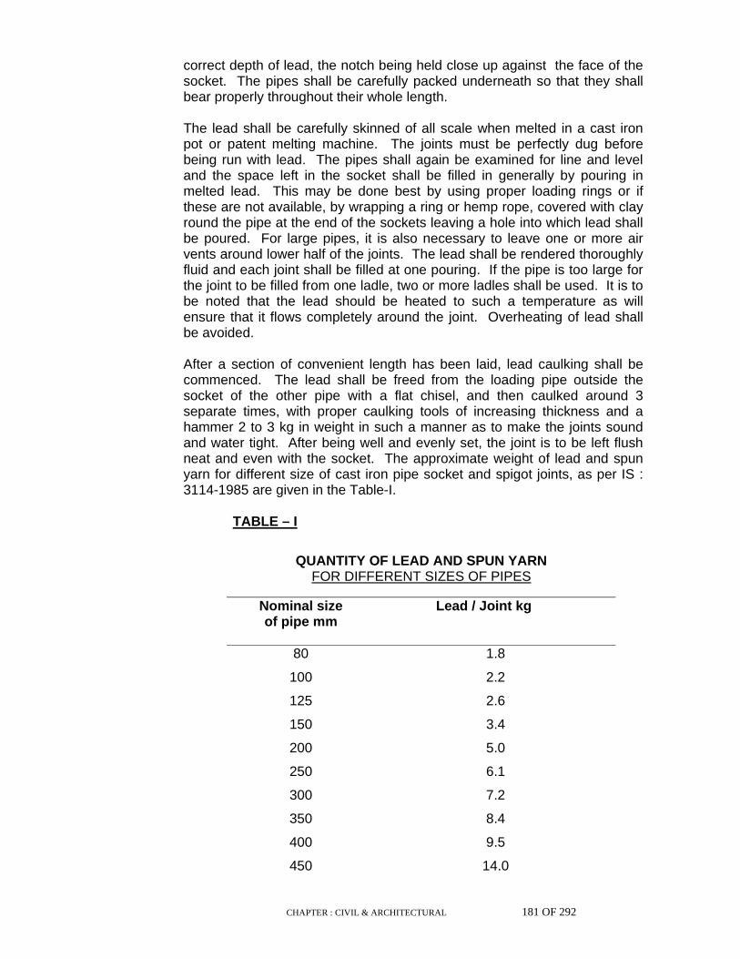
CHAPTER : CIVIL & ARCHITECTURAL 181 OF 292
correct depth of lead, the notch being held close up against the face of the socket. The pipes shall be carefully packed underneath so that they shall bear properly throughout their whole length.
The lead shall be carefully skinned of all scale when melted in a cast iron pot or patent melting machine. The joints must be perfectly dug before being run with lead. The pipes shall again be examined for line and level and the space left in the socket shall be filled in generally by pouring in melted lead. This may be done best by using proper loading rings or if these are not available, by wrapping a ring or hemp rope, covered with clay round the pipe at the end of the sockets leaving a hole into which lead shall be poured. For large pipes, it is also necessary to leave one or more air vents around lower half of the joints. The lead shall be rendered thoroughly fluid and each joint shall be filled at one pouring. If the pipe is too large for the joint to be filled from one ladle, two or more ladles shall be used. It is to be noted that the lead should be heated to such a temperature as will ensure that it flows completely around the joint. Overheating of lead shall be avoided.
After a section of convenient length has been laid, lead caulking shall be commenced. The lead shall be freed from the loading pipe outside the socket of the other pipe with a flat chisel, and then caulked around 3 separate times, with proper caulking tools of increasing thickness and a hammer 2 to 3 kg in weight in such a manner as to make the joints sound and water tight. After being well and evenly set, the joint is to be left flush neat and even with the socket. The approximate weight of lead and spun yarn for different size of cast iron pipe socket and spigot joints, as per IS : 3114-1985 are given in the Table-I.
TABLE – I
QUANTITY OF LEAD AND SPUN YARN
FOR DIFFERENT SIZES OF PIPES
Nominal size of pipe mm
Lead / Joint kg
80 1.8
100 2.2
125 2.6
150 3.4
200 5.0
250 6.1
300 7.2
350 8.4
400 9.5
450 14.0

CHAPTER : CIVIL & ARCHITECTURAL 182 OF 292
500 15.0
600 19.0
700 22.0
750 25.0
800 31.5
900 35.0
1000 41.0
1100 46.0
1200 50.0
1500 66.5
Note : The quantities of lead given are provisional and a variation of 20% is
permissible either way.
b) Lead wool joint
In the event of the Engineer specifying or permitting the use of lead wool the joint shall be made as follows :
Hempen spun yarn shall be driven into the socket and thoroughly caulked with suitable caulking tools. Lead wool shall then be introduced and this caulking shall be repeated with each turn of lead wool under which the socket is full within 3 mm and the wool of the lead wool is compressed into dense mass. The joint shall then be finally pressed with finishing tool. The table giving the quantity of lead wool and yarn to be used in different sizes of pipes is given in the Table-2
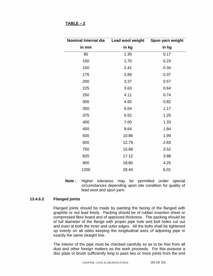
CHAPTER : CIVIL & ARCHITECTURAL 183 OF 292
TABLE – 2
Nominal Internal dia
in mm
Lead wool weight
in kg
Spun yarn weight
in kg
80 1.30 0.17
100 1.70 0.23
150 2.41 0.34
175 2.89 0.37
200 3.37 0.57
225 3.63 0.64
250 4.11 0.74
300 4.82 0.82
350 6.04 1.17
375 6.52 1.25
400 7.00 1.33
450 9.64 1.84
500 10.86 1.99
600 12.79 2.83
750 15.68 3.52
825 17.12 3.88
900 18.80 4.25
1200 28.44 6.01
Note : Higher tolerance may be permitted under special
circumstances depending upon site condition for quality of lead wool and spun yarn.
13.4.6.2 Flanged joints Flanged joints should be made by painting the facing of the flanged with
graphite or red lead freely. Packing should be of rubber insertion sheet or compressed fibre board and of approved thickness. The packing should be of full diameter of the flange with proper pipe hole and bolt holes cut out and even at both the inner and outer edges. All the bolts shall be tightened up evenly on all sides keeping the longitudinal axes of adjoining pipe in exactly the same straight line.
The interior of the pipe must be checked carefully so as to be free from all
dust and other foreign matters as the work proceeds. For this purpose a disc plate or brush sufficiently long to pass two or more joints from the end
CHAPTER : CIVIL & ARCHITECTURAL 184 OF 292
of the pipe last laid shall be continuously drawn forward as the pipes are laid. The ends of the pipes must be securely protected preferably with wooden plugs during the process of the work. The pipes laid must not be made receptacles either for tools, cloth or any other material during progress of the work.
13.4.7 Inspection & testing
a) If required all materials shall be inspected by the Engineer before dispatch to site. All the tests shall be carried out in the manufacturer's works and necessary test certificates shall be furnished as proof of such testing. The Contractor shall intimate the Engineer at least two weeks in advance for any such inspection / testing. All facilities for inspection / testing including necessary test certificates shall be provided by the Contractor at his own cost.
b) After completion of erection all pipelines shall be inspected by the
representative of the Contractor and the Engineer. Any discrepancy, defect pointed out during this inspection shall be made good by the Contractor to the entire satisfaction of the Engineer without additional cost.
c) All pipes with valve and fittings shall be tested to 1.5 times maximum
working pressure. The pressure should remain constant for a period of 8 hours. All arrangements for testing shall be done by the Contractor. Any defect found during testing shall be made good by the Contractor to the entire satisfaction of Engineer and the test shall be repeated till acceptable results are achieved. Any special tools, instrument or equipment required for these tests shall be provided by the Contractor for tests only.
d) All oils, lubricants and other consumables required during tests and
trials of different equipment shall be supplied and arranged by the Contractor at his own cost.
13.4.8 Painting
i) All equipment, valves and other exposed steel parts shall be given a coat of red oxide, zinc chromate or red lead and two coats of final approved quality paint according to the colour scheme of the Purchaser.
ii) All the exposed pipes and fittings shall be painted with two coats of
paints of approved quality. 13.4.9 Commissioning After pressure testing the main, it should be flushed with water of sufficient
velocity to remove all dirt and foreign materials. The system shall be commissioned after all necessary tests have been
conducted successfully. All lubricants, oils, and other consumables required for commissioning of the system shall be supplied by the

CHAPTER : CIVIL & ARCHITECTURAL 185 OF 292
Contractor at no extra cost. Commissioning of the equipment to be supplied, if any, by the Owner, shall be carried out by the Contractor under guidance of the representatives of the supplier of these equipment and Engineer. Any adjustment and/or changes/ rectifications that may be found necessary during commissioning of these equipment shall be carried out by the Contractor at his cost.
13.5. Stoneware Glazed Pipelines (S.W.G) 13.5.1 Back filling Trenches shall not be back filled until the pipe joints have been tested,
alignment and gradient passed by the Engineer, but back filling shall be done at least for a depth equal to the diameter of the pipe or 300 mm whichever is greater over the pipes leaving 450 mm on either side of the joints uncovered with earth till the testing is completed. These joints should however be kept covered with mats, gunny bags, straws etc., to avoid damage to joints by temperature effects.
While back filling care should be taken to ensure that no damage is done to
the pipelines. The first 300 mm of filling material immediately over and around the pipe should be of soft material free from clods and stones etc. The remainder of the filling materials shall be watered and rammed in layers not exceeding 250 mm at a time.
Paving and metalling shall be reinstated in as good order as before laying
of the pipelines. Unless otherwise required by the Engineer, there shall be a minimum cover
of 700 mm over the pipes and at road crossing etc., it shall not be less than 900 mm.

CHAPTER : CIVIL & ARCHITECTURAL 186 OF 292
13.5.2 Laying of pipes The laying of the pipelines shall commence only after the levels of the
bottom of the trench at various points have been checked by the Engineer. Cracked pipes whether at the socket or in the body shall be rejected. All SW pipes shall be fitted together on the surface of the ground to ensure a proper fit before they are lowered. The spigots and sockets shall be properly cleaned and brushed, if necessary & then lowered by hand to the bottom of the trench.
The pipes shall be carefully laid to the alignment, levels and gradients
shown on the plans and sections, and great care shall be taken to prevent, sand, earth or other matter from entering the pipes during laying. As it is not permitted to rectify errors of grade by packing up underneath with earth, care should be taken in excavating and slight scraping, if necessary, done to bring to grade. The pipes between manholes shall be laid truly in straight lines without vertical or horizontal undulations.
Bedding, haunching or encasing of the pipes during laying shall be in
accordance with IS : 4127-1983 and shall be done with cement concrete in proportion (1:4:8) to prevent ground water from entering the pipelines.
All inverts shall be laid from site rail fixed at the true levels, with proper
boning rod. The sight rails and boning rods shall be provided, fixed and maintained by the Contractor at his own expense.
The pipes shall be laid, sockets facing up the gradient, beginning at the
lower end, and with the sockets, resting in the socket rest holes cut in the trench bottom. Each pipe shall be laid singly and no pipe shall be laid until the trench has been excavated to its required depth to a distance of twenty yards in front of the pipes to be laid.
No pipes of any description shall be covered until they have been passed
by the Engineer. 13.5.3 Jointing of pipes
(a) Cement joint
The stoneware pipes shall be cement jointed normally. In case, if specified so, bituminous joints shall be used. In each joint, spun yarn soaked in neat cement slurry or gasket of tarred yarn shall be passed round the joint and inserted in it by means of suitable jointing tools. More skeins of spun yarn or gasket shall then be added and well rammed home. The yarn shall be moistened to avoid absorbing moisture from cement mortar.
The yarn should be so placed as to centre the spigot of one pipe
within the socket of the other and shall prevent the jointing mortar penetrating inside the pipe where it might set and interfere with the flow of sewage.
CHAPTER : CIVIL & ARCHITECTURAL 187 OF 292
Yarn or gasket (cemented or tarred) so rammed shall not occupy
more than one-fourth of the depth of socket. The cement shall be thoroughly mixed with medium sand in the
proportion of 1:1 (1 cement : 1 sand) and then just enough water shall be added to make the mix plastic. On no account, the mortar shall be made soft or sloppy. The mix shall then be carefully inserted by hand into the joint.
Special care shall be taken for inserting the mortar into the portion of
the joint underneath the pipe. When the cement mortar has been inserted, it shall be punched or caulked into the joint with wooden caulking tools, and more cement mortar shall be added until the space of the joint has been filled completely with tightly caulked cement. No fillet of cement shall be added.
No mortar which is older than 30 minutes shall be permitted for
jointing. The cement mortar joints shall be cured at least for seven days before testing.
The inside of each pipe shall be carefully wiped out with a mop or
scrapper sufficiently long to pass two joints from the end of the pipe and any projecting cement shall be removed.
All pipes entering the manholes should be set in cement mortar 1:3
and a completely watertight junction effected.
(b) Bituminous joints
If specified so this joint will be used. Asphalt and sand in the ratio of 1:7 shall be boiled together and filled into the socket in a molten state with the aid of special moulds.
13.5.4 Testing of pipes Testing of pipes shall be done wholly at contractor's expense inclusive of
apparatus, provision of water etc., and/or as per IS : 4127-1983. After cement has had time to set, the pipes shall be tested in lengths
between manholes in the following 'manner'. In the lowest manhole a plug shall be inserted in the pipe. The disc in the pipe and at the upper manhole shall be fitted with a filling pipe with a right angle bend and an air cock. The length of pipe shall then be filled with water by means of the pipe connection on the upper disc. The air cock in the upper disc shall be kept open, while the pipeline is being filled to permit the escape of air.
When the pipes have been filled with water and air excluded, the air cock
shall be shut and water shall be poured into a conical "Filler" attached to the testing and filling pipe of the disc in the upper manhole until water remains in the filler. The testing or filling pipe shall then be raised and fastened so that the height of the pipe is six feet, which will be the usual test pressure for stone ware pipe joints.

CHAPTER : CIVIL & ARCHITECTURAL 188 OF 292
The test will be for an hour or such longer period as may be set by the
Engineer. If the water level does not fall more than 25 mm in the length of 90 metre, the test may be considered satisfactory.
If it is found that certain pipe joints are leaking, the water shall be run off
and joints recaulked with cement mortar and the test repeated till it is proved by the Contractor that the joints are leak-proof.
13.5.5 Concrete bedding, haunching & encasing Unless otherwise specified in the Schedule of Quantities, all SW pipes shall
be laid in accordance with IS: 4127-1983 As per site condition haunching or/and encasing of pipes with cement concrete may be required as per clause 4.2 & 4.3 of IS 4127-1983. The concreting shall be done with 1:4:8 cement sand concrete.
Where sewers have less than 1.2 m cover at places of heavy traffic, these
shall be surrounded with mass concrete if directed by the Engineer. 13.5.6 Handling of pipes While unloading, pipes shall not be dropped from the trucks/carts on the
ground. Timber skids and steadying rope should be used while unloading or lowering in trenches. To avoid damage specially to spigot end, pipes should not be dragged on the hard surface.
13.6 Manholes All manholes shall be of the size and type as given in the Schedule and
shall be provided as per drawing or as directed by the Engineer. All the manholes shall be circular or other shape as shown in drawing. The bed shall be in cement concrete of Mark-10B (or 1:3:6 mix) (Size of coarse aggregate 40 mm and down) of 100 mm thickness or as shown in the drawing and shall be projected out 75 mm from the outside face of the wall all round. or as shown in the drawing. The working part including channelling, benching etc., made of P.C.C. shall be of grade-15C (or 1:2:4 mix). All manholes shall be plastered inside with 1:3 cement plaster 20 mm thick and finished with a floating coat of neat cement unless otherwise specified.
Concrete used for precast RCC cover slabs shall be of grade 20C (or
1:1.5:3 mix)and shall be constructed as per drawing. The top level of manholes shall be generally 100 mm above the
surrounding ground levels or as directed by the Engineer. Channelling inside the manhole shall be done in smooth bends.
The end of pipe shall be neatly built in and finished in cement mortar 1:3. Circular medium duty Cast iron water sealed manhole cover and frames,
560 mm dia (clear opening) and nominal weight 128 kg shall be provided for each manhole and shall be in accordance with IS:1726-1991
CHAPTER : CIVIL & ARCHITECTURAL 189 OF 292
Manhole covers with double seals (Light duty) with wt. as specified in schedule of item shall be provided within compound near the buildings if specified so. If specified heavy duty cover and frames, either circular or double triangular type, shall be provided. Step irons shall be provided with two coats of bituminous paint and shall be as per drawing.
In cases where branch pipe sewers enter the manhole or main pipe sewer
at a level more than 1m, from the main sewer, a drop connection shall be provided. The extra pipe length required for this connection will be paid under item for pipelines. No other extra payment will be allowed.
All exposed surfaces of cast iron frame and cover shall be painted with two
coats of bituminous painting 13.7 Marker plates Marker plate indicating the particular service installed shall be provided
along the routes of pipes laid below ground. These shall be of mild steel, with the type of service and direction of flow, painted on it. The markers shall be set firmly in a concrete base and installed at all corners and turning points. Over straight runs markers shall be spaced at 100 m intervals generally.

CHAPTER : CIVIL & ARCHITECTURAL 190 OF 292
14.0 ROAD WORK 14.1 General Road works in general shall be constructed according to the requirements
to the various specifications and codes of practices of the Indian Roads Congress.
Works such as earthwork, masonry, concreting and the like, wherever they
occur in association with construction of roads, shall be governed by the respective specifications of these series.
14.2 Trenching and Preparation of Subgrade The surface of the formation of width equal to that of soling coat shall first
be cut to a depth below the proposed finished level equal to the combined depth of soling and wearing coat, (due allowance being made for consolidation), and dressed parallel to the finished profile. Any roots of bushes, trees etc., shall be taken out to the full depth and the cavities thus formed shall be filled up and rammed by the contractor at his cost.
In slushy soil or in areas where water logging is frequent, adequate
arrangement shall be made for drainage of the area so that the sub-soil water level is kept as low as possible.
The sub-grade shall then be consolidated with a power road roller of 8-10
tonne capacity by rolling with minimum of 5 numbers of passes till it is densely consolidated to the satisfaction of the Engineer.
Surplus earth shall be disposed of as directed by the Engineer and the
areas where it is disposed of shall be neatly dressed. All undulations of the sub-grade surface that might develop due to rolling
shall be made good with earth and sub-grade re-rolled. 14.3 Ash / Moorum Carpet Wherever the ground is soft and slushy, ash carpet consisting of common
boiler ash shall be laid to 5 cm thickness over the subgrade and then rolled. In firm ground no ash carpet is necessary and boulder soiling shall be laid directly over the sub-grade. If decided by the Engineer, a bed of moorum of specified thickness shall be provided for to form a sub-grade.
CHAPTER : CIVIL & ARCHITECTURAL 191 OF 292
14.4.1 Boulder Soling The width of the soling coat shall be 30cm (15cm on either side) more than
that of the wearing coat. Its depth shall be 15cm in cutting and 23cm in filling and made up soil, unless otherwise specified in the schedule of quantities or shown in the drawing.
The edges of the soling shall be marked out by strings and stakes. Soling
stone shall be hand packed and set on edge with greatest length across the road. This shall be laid closely in position on the sub-grade, firmly set with their broadest side downwards. The joints shall be staggered. All interstices between the stones shall be wedged in with locking smaller stones well driven into gaps to ensure tight packing and complete filling of interstices. Such filling shall be carried out simultaneously with the placing in position of soling stones and shall not lag behind.
After packing, surface shall be checked with template of approved shape
and high and low spots corrected by removing soling and re-packing. The top surface of the soling coat shall be perfectly true to camber and grade.
The soling shall then be thoroughly consolidated with power roller of 8-12
tonne weight depending upon the type of soling stones, starting at "edges" and working towards the centre. In case of super-elevated curve the rolling shall commence from the inside edge of the curve to the outside edge. The roller shall run over the same surface of soling at least 10 times or more till the soling coat is well consolidated to the satisfaction of the Engineer. The surface shall be checked by templates and any disturbance in grade or camber corrected after every rolling and finally consolidated. After that, at least 50mm thick moorum shall be laid on top of soling coat and rolled with water to proper compaction so that the top surface seems smooth. The rate for soling coat shall be inclusive of the cost of the moorum as blinding materials for which no separate payment shall be made.
14.4.2 Laterite soling In case of laterite soling the thickness of soling shall be as follows :
(i) For road width of 7m and above the sub-base shall consist of two layers of laterite stones 150mm maximum size. The sub-base shall be rolled to a thickness of 230mm after compaction.
(ii) For road width of 4m to 7m,the sub-base shall consist of one layer of
laterite stone of 150mm maximum size consolidated to 115mm thick. (iii) A layer of moorum,33.3 % in volume of laterite, shall be spread over
the laterite to a uniform thickness and rolled with 8 tonne roller with constant watering until the mixture penetrates into the voids of laterite layer. Care shall be taken to maintain the camber and slopes.
Other steps for laying, compacting etc. of the laterite soling shall be same
as given under clause 14.4.1 "Boulder soling".
CHAPTER : CIVIL & ARCHITECTURAL 192 OF 292
14.5 Kerbs Concrete or stone kerbs, where shown in drawings, shall be fixed in
position after laying and consolidation of soling. They shall be fixed true to line and level and secured in position by approved means.
14.6 Water Bound Macadam Surfacing The construction of water bound macadam shall be carried out according to
IRC : 19-1981 "Standard Specification and Code of Practice for Water Bound Macadam".
14.7 Preparation of Base and Shoulders The subgrade shall be reshaped to the required grade and camber. Where
water bound macadam is to be laid over existing black top surface, 50 mm x 50 mm furrows shall be cut in the existing surface at 1 m intervals inclined 45 degree to the centre line of the carriageway, before laying of coarse aggregates. Necessary arrangements shall be made for the lateral confinement of aggregates by constructing shoulders in the form of two parallel mud walls 20 x 15cm which shall be made along the outer edges of the wearing course.
14.8 Spreading Coarse Aggregate The coarse aggregates shall be spread uniformly and evenly upon the
prepared base in required quantities from stock piles along the roadside or directly from vehicles. In no case shall these be dumped in heaps directly on the base. The aggregates shall be spread to proper profile by using templates placed across the road about 6m apart. Where possible, mechanical devices shall be used to spread the aggregates uniformly.
The water bound macadam course shall be constructed in layers of not
more than 75 mm thickness. However, the Engineer may permit courses of 100 mm compacted thickness to be constructed in a single layer. Each layer shall be tested by depth blocks. No segregation of large or fine particles shall be allowed.

CHAPTER : CIVIL & ARCHITECTURAL 193 OF 292
14.9 Rolling The coarse aggregates spread as described above shall be compacted to
full width by rolling with either three wheel power roller of 6 to 10 tonnes capacity or an equivalent vibratory roller. The weight of roller shall depend on the type of coarse aggregate.
The rolling shall begin from edges and after the edges have been
compacted, progress gradually towards the centre, parallel to the centre line of the road, uniformly lapping each preceding rear wheel track by one half width. On super elevated portions, rolling shall commence from the lower edge. Where screenings are to be applied, rolling shall be discontinued when the aggregates are partially compacted with sufficient voids to permit application of screenings. Where screenings are not to be applied, as in the case of crushable aggregates compaction shall be continued until the aggregates are thoroughly keyed, with no creeping of stones ahead of the roller. Slight sprinkling of water may be done during rolling, if necessary.
Rolling shall not be done when the subgrade is soft or yielding nor when it
causes a wave like motion in the base course. If irregularities develop during rolling, and exceed 12 mm when tested with a 3m straight edge, the surface shall be loosened and aggregates added or removed before rolling again. The surface shall be checked by template for camber. In no case shall screenings be used to make up depressions.
14.10 Application of Screenings After coarse aggregates have been rolled, screenings to fill the interstices
shall be applied gradually over the surface in thin layers. Dry rolling shall be done when the screenings are being spread, so that the jarring effect of roller causes them to settle into the voids of the coarse aggregates. Damp and wet screenings shall not be used and the spreading, rolling and brooming of screenings shall be taken up on sections which can be completed within one day's operation.
14.11 Sprinkling and Grouting After application of screenings, the surface shall be copiously sprinkled with
water, swept and rolled. The sprinkling, sweeping and rolling operations shall be continued and additional screenings applied where necessary until the coarse aggregates are well blended and firmly set and a grout of screenings and water forms ahead of the wheels of the roller.

CHAPTER : CIVIL & ARCHITECTURAL 194 OF 292
14.12 Application of Binding Material After the application of screenings, approved binding material, where it is
required to be used, shall be applied at a uniform and slow rate in two or more successive thin layers to a thickness of 2.5 cm. After each application of binding material, the suface shall be copiously sprinkled with water and the resulting slurry swept in with brooms, so as to fill the voids properly. This shall be followed by rolling with a 6-10 tonne roller, during which, water shall be applied to the wheels to wash down the binding material that may get stuck to them. The spreading of binding material, sprinkling of water, sweeping with brooms and rolling shall continue until the slurry of binding material and water forms a wave ahead of the wheels of moving roller.
14.13 Setting and Drying After final compaction the road shall be allowed to cure overnight. Next
morning, hungry spots shall be filled with screenings or binding material, lightly sprinkled with water and rolled. No traffic shall be allowed till the macadam sets.
14.14 Surface Evenness The surface evenness of completed water bound macadam course in
longitudinal direction shall be within 12 mm when tested with a 3 m straight edge and in cross profile within 8 mm when checked with a template.
14.15 Bituminous Pavements 14.15.1 Bitumen premix carpet with seal coat The consolidated thickness of this type of treatment shall be
2cm/2.5cm/4cm or as specified. 14.15.1.1 Surface preparation Water bound macadam surface on which black topping is to be provided
shall be thoroughly cleaned of dust, loose materials, caked mud and other foreign material with the help of wire brush, chisel, picks etc. Cleaning shall be such as to expose the stone metal to a depth of about 6mm without dislodging the interlock of the metal. All dust and other materials thus removed shall be thrown away at a suitable place as directed by the Engineer.
Any potholes, depressions and undulations found after cleaning shall be
made good with premixed chippings, and well rammed. 14.15.1.2 Tack coat Just before the application of tack coat, the surface shall be thoroughly
cleaned by brooms and then by fanning with gunny bags.
CHAPTER : CIVIL & ARCHITECTURAL 195 OF 292
Bitumen of specified grade heated to a temperature of 177 to 188 degree
'C' shall be spread on the prepared surface uniformly at the rate of 0.75 kg/sq.m. by means of sprayers. It shall be applied just ahead of and keeping pace with, laying of premix carpet.
14.15.1.3 Preparation of mix, laying & consolidation The stone grit (aggregate) shall be surface dry and contain not more than
2% moisture before use. It shall be first screened of dust and measured in boxes and then loaded into the drum mixer according to the capacity of the mixing drum in the proportion given in the table below. The aggregate shall be heated to facilitate mixing with the binder in cold weather, where so directed by the Engineer.
The binder heated in boilers, to a temperature of 149 to 177 degrees C or
as specified for the grade used and maintained to that temperature, shall be drawn off from the boiler into a suitable container or in bucket gauged to show the weight of bitumen in it. This shall then be poured over the aggregate in the mixer at the correct rate of 64 Kg/cum of aggregate or as specified and mixing started and continued till aggregate is uniformly coated with bitumen.
Immediately after applying the tack coat, the hot mix shall be discharged
from the mixer, carried to the road surface and spread to a thickness sufficient to achieve after consolidation the specified thickness. Rakes or drag spreaders shall be used for spreading the mixture.
When the premix has been laid for a length of 15-20 metres it shall be rolled. Rolling shall commence from edges and proceed towards the centre. The roller wheels shall be moistened continuously so as to prevent metal chips sticking to it. Any high spot or depression which become apparent shall be corrected by addition or removal of premix materials.
Further the prepared finished surface shall be protected from the traffic for
24 hrs or such period as may be specified by the Engineer.

CHAPTER : CIVIL & ARCHITECTURAL 196 OF 292
14.15.1.4 Materials
Quantity of materials required per 100 sqm of road surface shall be as given in the table below, unless otherwise specified.
Binder Sl.
No. Consolidated thickness of
premix carpet
Stone chips (cum)
Sand (cum) Tack
coat (kg)
Carpet (kg/cum)
Seal coat
(kg/cum)Using Paving bitumen80/100 or 30/40 grade
1. Priming tack coat
a) on a water bound macadam surface
75
b) on an existing
black top surface
65
2. Carpet 2 cm 2.4 (10 mm
nominal size) 64
2.5 cm 3.0 (10 mm
nominal size) 64
4.0 cm 4.8 (12 mm
nominal size) 64
3. Seal Coat a) Dry area (Premixed
sand seal coat) 0.6 68
b) Wet area (Liquid seal coat with chips
0.9 98
14.15.2 Seal coat In dry areas where rainfall is under 150cm per year a premix sand seal coat
shall be applied immediately after laying the carpet. The binder shall be heated in boilers of suitable design, to the temperature appropriate to the grade of bitumen. The aggregates shall be dry and suitably heated to a temperature directed by Engineer before the same are placed in the mixer of suitable design. Mixing of binder with aggregates to the specified proportions shall be continued till the latter are thoroughly coated with binder. The mix shall be immediately transported from the mixing plant to the point of use and spread uniformly on the bituminous surface to be sealed. As soon as sufficient length has been covered with premix materials, the surface shall be rolled with 6 to 8 tonne power roller. Rolling shall be continued till the premix material completely seals the voids in the bituminous course and a smooth uniform surface is obtained.

CHAPTER : CIVIL & ARCHITECTURAL 197 OF 292
In wet areas where rainfall is above 150cm per year a liquid seal coat with
chippings (not sand) shall be applied after laying the carpet. The binder shall be heated in boilers of suitable design, to the temperature appropriate to the grade of bitumen and spread on the surface preferably using mechanical sprayers. Immediately following the application of the binder, stone chippings in a perfectly dry condition shall be uniformly spread on the surface. Immediately after the application of the cover material, the entire surface shall be rolled with 8-10 tonne road roller.
14.15.3 Surface dressing The surface shall be prepared in the same way as that for premix carpet
work as per 14.15.1.1. Depression or pot holes, if any, shall be repaired as indicated.
After the surface has been prepared and is in perfectly dry condition,
bitumen heated in the same manner as for premix carpet, shall be sprayed over the surface preferably using mechanical sprayers. It shall be ensured that there is even and uniform distribution of bitumen on the surface. Spraying shall be carried out parallel to the centre line of the road.
Immediately following the application of bitumen, stone chippings in a
perfectly dry condition, shall be uniformly and evenly spread as specified in the item, over the entire sprayed surface. Spreading may be done preferably by means of mechanical gritter. Finally the entire surface shall be broomed to ensure perfect uniform spreading.
The final surface shall be checked by means of camber board etc. The
spread surface shall be rolled with 6 to 8 tonne roller till there is sufficient boundage of chippings with bitumen. The finished surface shall be thrown open to traffic on the following day.
14.15.4 Premixed Bitumen Concrete 14.15.4.1 General In this type of road carpet a mixture of sand and stone aggregate is used as
aggregate producing a dense mixture. Seal coat is not necessary as the sand used in the mix works up to the surface and forms a seal by itself. The consolidated thickness of this type of treatment shall vary from 4cm to 7.5cm as specified.
14.15.4.2 Surface Preparation
Same as in para 14.15.1.1 above. 14.15.4.3 Tack Coat
Same as in para 14.15.1.2 above. 14.15.4.4 Preparation of Mix, Laying & Consolidation
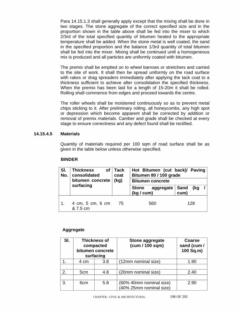
CHAPTER : CIVIL & ARCHITECTURAL 198 OF 292
Para 14.15.1.3 shall generally apply except that the mixing shall be done in
two stages. The stone aggregate of the correct specified size and in the proportion shown in the table above shall be fed into the mixer to which 2/3rd of the total specified quantity of bitumen heated to the appropriate temperature shall be added. When the stone metal is well coated, the sand in the specified proportion and the balance 1/3rd quantity of total bitumen shall be fed into the mixer. Mixing shall be continued until a homogeneous mix is produced and all particles are uniformly coated with bitumen.
The premix shall be emptied on to wheel barrows or stretchers and carried
to the site of work. It shall then be spread uniformly on the road surface with rakes or drag spreaders immediately after applying the tack coat to a thickness sufficient to achieve after consolidation the specified thickness. When the premix has been laid for a length of 15-20m it shall be rolled. Rolling shall commence from edges and proceed towards the centre.
The roller wheels shall be moistened continuously so as to prevent metal
chips sticking to it. After preliminary rolling, all honeycombs, any high spot or depression which become apparent shall be corrected by addition or removal of premix materials. Camber and grade shall be checked at every stage to ensure correctness and any defect found shall be rectified.
14.15.4.5 Materials Quantity of materials required per 100 sqm of road surface shall be as
given in the table below unless otherwise specified.
BINDER
Hot Bitumen (cut back)/ Paving Bitumen 80 / 100 grade Bitumen concrete
Sl. No.
Thickness of consolidated bitumen concrete surfacing
Tack coat (kg)
Stone aggregate (kg / cum)
Sand (kg / cum)
1. 4 cm, 5 cm, 6 cm
& 7.5 cm 75 560 128
Aggregate
Sl. Thickness of compacted
bitumen concrete surfacing
Stone aggregate (cum / 100 sqm)
Coarse sand (cum / 100 Sq.m)
1. 4 cm 3.8 (12mm nominal size) 1.90 2. 5cm 4.8 (20mm nominal size) 2.40 3. 6cm 5.8 (60% 40mm nominal size)
(40% 25mm nominal size) 2.90
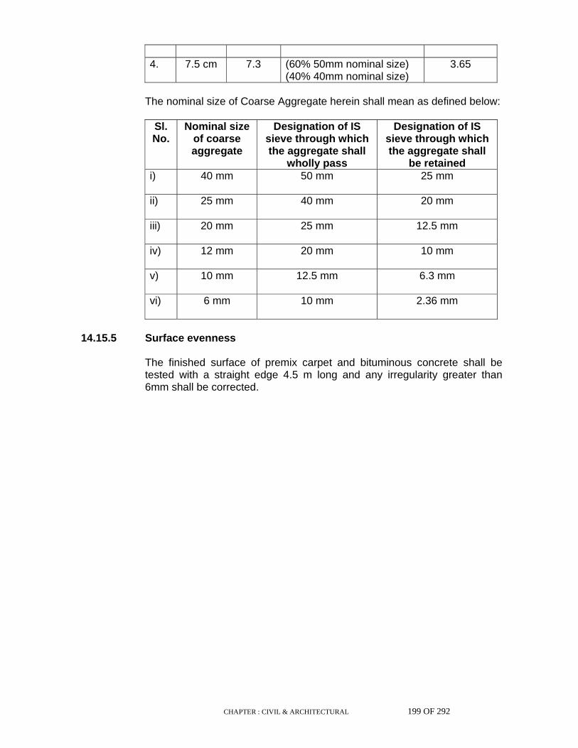
CHAPTER : CIVIL & ARCHITECTURAL 199 OF 292
4. 7.5 cm 7.3 (60% 50mm nominal size)
(40% 40mm nominal size) 3.65
The nominal size of Coarse Aggregate herein shall mean as defined below:
Sl. No.
Nominal size of coarse aggregate
Designation of IS sieve through which the aggregate shall
wholly pass
Designation of IS sieve through which the aggregate shall
be retained i) 40 mm 50 mm 25 mm
ii) 25 mm 40 mm 20 mm
iii) 20 mm 25 mm 12.5 mm
iv) 12 mm 20 mm 10 mm
v) 10 mm 12.5 mm 6.3 mm
vi) 6 mm 10 mm 2.36 mm
14.15.5 Surface evenness The finished surface of premix carpet and bituminous concrete shall be
tested with a straight edge 4.5 m long and any irregularity greater than 6mm shall be corrected.
CHAPTER : CIVIL & ARCHITECTURAL 200 OF 292
14.16 Berms Shoulders and berms shall be prepared as shown on the drawings. Work
on making berms shall not lag more than 100 metres behind the water bound macadam consolidation. Suitable drains shall be cut on the berms so that the water bound macadam surface is kept drained till bituminous macadam is laid.
14.17 Kerbs Kerbs shall be laid and set in place before completing the bituminous or
concrete wearing surface as well as the wearing surface of footpath. Setting shall be done in mortar where so specified with Schedule of Items. They shall be laid and set in such a way as to obtain straight lines in the finished work, the top surface matching with the finished surface of footpath.
Where the road edge forms a curve, the kerbs shall follow such curve.
Gaps shall be left as shown in drawings or as may be required to provide for drainage.
14.18 Bridges and Culverts Bridges and culverts shall be constructed according to the specifications of
Indian Roads Congress. Relevant chapters of earthwork, concrete, masonry etc., of these series shall apply.
14.19 Boulder Pitching Wherever specified, boulder pitching shall be provided at the inlet and
outlet of pipe culverts, or for embankments of bridges. The subgrade shall first be dressed to level or slight slope as indicated. The transverse slope of the pitching shall be made strictly in accordance with the drawings or as directed by the Engineer.
14.20 Scarifying & Dismantling Where a new carriage-way abuts or includes an existing carriage-way and
the Engineer so directs, the surface of the latter shall be scarified, adjusted and reshaped to conform with the existing and new camber or crossfall. Materials from the existing road shall be used or disposed off as directed by the Engineer.
Where dismantling of the existing road has been specified, the various
layers of the road viz., bituminous macadam, water-bound macadam and soling shall be scarified separately. Scarifying can be done either by hand picks, or by means of scarifiers fixed to the roller. When a roller is used for scarifying, crushing of the metal shall be avoided by moving the metal clear of roller wheels after the scarifier has passed over it. The loosened material shall then be combed by means of rakes to bring out most of the larger stone. If necessary, the larger stones thus collected shall be screened to separate fine particles if any.

CHAPTER : CIVIL & ARCHITECTURAL 201 OF 292
The remaining metal shall then be removed and screened to recover
reusable metal. Different grades of metal shall be stacked separately and measured.
14.21 Diversions Where the construction of the road or culvert or bridge is in progress, the
road shall be closed to traffic and a suitable diversion shall be provided for traffic by the Contractor, as directed by the Engineer.
The road shall be closed by the erection of barriers and suitable sign
boards at both ends which shall be provided with lights at night. Both during night and during day, one man shall be posted at each barrier to suitably divert the traffic and to keep the light burning during the night.

CHAPTER : CIVIL & ARCHITECTURAL 202 OF 292
15.0 WATERPROOFING TO ROOFS & WATERPROOFING
PAINTS 15.1 Scope This chapter deals with different types of waterproofing on roof. 15.2 Material The materials shall conform to Part-I. 15.3 General Workmanship The waterproofing to roofs being specialised works the Contractor shall get
these done by specialised firms/agencies. 15.4 Painting with Hot Bitumen The surface to be painted shall be thoroughly dried and then cleaned, with
wire brushes and cotton or gunny cloth, of all loose materials and scales. The surface shall further be cleaned with a piece of cloth lightly soaked in kerosene oil. Bitumen shall be brought to the site in its original container and this shall not be removed from site till the painting job is completed. Before applying the main coatings of hot bitumen paints, one coat of bituminous primer shall be applied. The number of coats of hot bitumen shall either two coats or as specified in the Schedule of Items. The bitumen of approved quality (either of grade 80/100 or 30/40) or as specified shall be applied to the surface after heating it to the manufacturer's specifications. Care shall be taken to see that no blank patches are left and the quality of bitumen to be spread shall be as specified and shall be to the satisfaction of the Engineer.
15.5 Painting with Bitumen Emulsion Before applying, the surface shall be cleaned thoroughly. Generally two
coats of Bitumen Emulsion are provided over a coat of emulsion primer. Since the painting is with emulsion, the surface need not be made dry.
15.6 Waterproofing of Roof 15.6.1 With bitumen felt Prior to laying the insulation, roof gradient shall be checked. If necessary,
the roof shall be re-graded by screed to ensure everywhere a run off gradient of not less than 1 in 120. The screed shall consist of one part cement and four parts medium to coarse sand by volume. The screed shall be cured for 7 days. The surface shall then be cleaned of all foreign matter by wire brushing and dusting.
Waterproofing unless specified otherwise in drawings shall be the "heavy
treatment type" with primer coat as described in IS : 1346-1991. The method of laying roofing treatment, surface finishing with pea gravels,

CHAPTER : CIVIL & ARCHITECTURAL 203 OF 292
special mode of treatment for drain outlets, projecting pipes, parapet walls, expansion joints, gutters, timber roofs etc., shall conform to IS : 1346-1991. The number of layers of felts shall be as specified in the drawing or Schedule of Items. The bonding bituminous material shall be of grade 30/40 or as specified and the minimum quantity of hot bitumen to be applied, shall be 1.2 kg/m2. Unless specified otherwise, the bituminous felts shall be hessian bases of Type-3 Grade-2. Pea gravel finish may be substituted by a coat of bituminous aluminium paint, where so specified in the Schedule of Items.
The cement mortar used for filling the chases shall be of mix 1:4 and the
cement concrete for fillets shall be of the same grade as the roof slab. Where special surface finish with precast concrete or clay tiles is specified,
it shall be in accordance with the relevant chapter of this series. 15.6.2 With bitumen mastic The work shall be carried out generally in accordance with IS : 4365-1967
"Code of Practice for Application of Bitumen Mastic for Waterproofing of Roofs" or according to the manufacturer's specifications. The work shall be carried out by a firm of specialists in the trade.
The type of underlay or primer, thickness of application, surface finish etc.,
shall be as shown on drawing or described in the Schedule of Items. Bitumen melting shall be done in a mechanical mixer by gradually heating to about 200 degree 'C'. Coarse aggregate where required shall be added to the hot bitumen and stirred.
Each coat shall be spread evenly and uniformly by means of a float to the
required thickness. Timber gauges shall be used to regulate the thickness. Particular care shall be taken to tuck the mastic into grooves on vertical surfaces, at joints, around pipes or other projections and at junction of adjoining bays.
15.6.3 Waterproofing of RCC roof with Lime concrete and Pressed clay titles. Lime concrete shall consist of broken brick aggregates and lime. Proportion
of brickbat coba shall be 2.5 parts of brick jelly to one part of lime. The brick jelly shall be hard, well burnt and of size varying from 12mm to 25mm.
The lime concrete is then laid over roof to slope to give specified thickness
and in slope of 1 in 80 or as shown on the drawing for proper roof drainage as per roof drainage plan. The lime concrete is then to be beaten in the manner approved by the Engineer for 48 hours or as directed with hand beaters.
If the surface during the process of compaction becomes so uneven that water lodges in pools, the surface shall be pricked up, and fresh concrete
spread and consolidated as necessary to obtain an even surface.
CHAPTER : CIVIL & ARCHITECTURAL 204 OF 292
The concrete shall then be cured by sprinkling water and allowed to
harden for a period of not less than six days before laying the roof finish. Roof shall be finally finished with one coarse of machine pressed clay titles
20 mm thick laid over a 12mm thick of 1:3 mix cement mortar mixed with 5% crude oil by weight of cement mixed in mortar. The pressed clay tiles shall be immersed in water for two hours before being used. The side joints of the tiles shall be more than 60 mm thick set full in mortar. Before the work dries up completely, the tile joints shall be raked out and pointed with cement mortar 1:3 mixed with crude oil which shall be 5% by mass of cement. The joints shall be well rubbed over with thin bar trowel and excess of mortar scrapped off until the surface of the pointing attains a black polish and becomes hard. As the work proceeds, it shall be kept thoroughly wetted until the mortar has set firm and hard. Watering shall be continued for three weeks after construction.
Lime concrete and tiles shall be taken up the parapet walls to a height of
150 mm or as shown in the drawing. The specification of pressed clay titles shall be as given in IS:2690-1975
(Part-I). The specification of crude oil shall be as per IS:2119-1980. The areas around drain pipes shall be properly finished with provision of
adequate slope. The contractor shall give guarantee for any/all types of waterproofing for a
period of 7 years against bad of faulty material and construction and shall rectify the same at his own cost during the guaranteed period.
15.7 Waterproofing for Basement 15.7.1 The specification covers the requirements of waterproofing of basements,
tunnels, ducts, pits, bunkers, etc. The material used shall be bitumen felt type-3 of grade-2 conforming to IS :
1322-1982, together with the specified bonding material and primer. Waterproofing shall be provided on the outside of walls and top of the floors
and shall be carried 150 mm above ground level. The number of layers of bitumen felt to be used for walls and floor unless
otherwise shown in the drawing shall be :
i) For depths upto five metres below ground : 2 layers. ii) For depths beyond five metres : 3 layers.
The method of laying the bitumen felts and workmanship shall in general
conform to IS : 1609-1991. Waterproofing work shall be taken in hand only when the sub-soil water
level is at its lowest, the site shall be kept dry by adequate arrangements for pumping out water till the work has been completed. For this purpose
CHAPTER : CIVIL & ARCHITECTURAL 205 OF 292
drains shall be formed along the edges of the excavation but beyond the building line, with suitable collecting sumps. In case of large excavation areas where it is necessary to dewater under the floor, additional land drains shall be formed across the excavation, to adequately drain the area. Adequate arrangements shall be made to prevent the sides of excavation from slipping while the work is in progress.
The base concrete of mud-mat shall be rendered smooth by a 20 mm thick
sand-cement plaster (6:1). Any sharp corner over which the waterproofing course is to be laid shall be eased out by means of cement mortar fillets 7.5 cm in radius.
The surface must be dry before the next operation is carried out. Blown
bitumen conforming to IS : 702-1988 shall be applied hot over the prepared surface at the rate of 1.5 kg/m2 for the first layer and for every other subsequent layer(s). The laying of felt over the bitumen so applied shall always commence on the floor, and shall be carried to the walls only after treatment of the floor is complete. The minimum overlapping of joints at sides and ends of felts shall be 10 cm. Joints for subsequent layers of felt shall be staggered. All joints shall be completely sealed by blow lamp.
A protective flooring of either flat bricks in cement mortar 1:3 or 6 cm thick
cement concrete type M15B or a coat of cement sand plaster (1:3) 4 cm thick shall be constructed over the waterproofing treatment to prevent damage to the latter during subsequent construction of the structural floor.
The walls shall be treated in a similar way, the bitumen felts joining at the
base with the projecting felt laid over the mud-mat. The wall surface shall be made smooth, where necessary with a coat of cement plaster 1:5, the felts shall be laid as for the floor ensuring that the surface to be treated is dry and then a protective brick wall, half-brick nominal thickness shall be built in cement mortar 1:6 over the projecting mud-mat, the space between the wall and felt being grouted with cement slurry. Sufficient care shall be taken to ensure a perfect bond between the waterproofing on the floor and that on the walls.
The treatment on the wall shall be carried 150 mm above the surface of
ground and tucked into a grove 6.5 cm. wide and 7.5 cm deep, the chase being filled with cement mortar (1:4).
Where waterproofing is done to the roof of an underground structure, such
as a tunnel, it shall be done in a similar way. The structural concrete shall be rendered smooth, hot bitumen and bitumen felts applied in the same way as for the floor and walls, and over this shall be laid a protective layer of cement concrete grade M10C, 7.5 cm thick.
15.7.2 With epoxy based emulsion Over the mud-mat a 20 mm plaster is to be provided to make the surface
even.

CHAPTER : CIVIL & ARCHITECTURAL 206 OF 292
On the plastered surface of the mud-mat, three coats of epoxy based
leakproof emulsion shall be applied with reasonable gap between each coat in order to permit sufficient drying time.
Precaution should be taken that during the process of rod binding if any
damages happens it should be immediately rectified by making patch painting on the affected portion only and as such a complete vigilance is to be kept to rectify the defect.
After the rod binding is over the concreting should be done with high
polymer based, chloride and sulphide free cement waterproofing additive/admixtures @ 2% by weight of cement all through the floor area and all through the vertically raised walls of four sides which shall remain underground upto a depth of 8 metre and above from ground level.
After the concreting and immediately after de-shuttering cleaning of the
concrete surface on the external faces of the walls are to be done and then three coats of epoxy based leakproof emulsion shall be applied with a reasonable gap between the each coat before back filling. If the back filling is with hard material again a protective layer of plaster shall also be applied on the external faces of walls in order to avoid damages on the painted surface.
If the back filling is with soft sandy or alluvial soil there is no necessity for
protective layer of plastering as mentioned above. Epoxy based paint can be applied on the wet surface hence there shall be
no stoppage of the normal progress of the project works. 15.8 Surface Application Waterproofing done by surface application of bitumen based or epoxy
based material shall conform strictly to the recommendations of the manufacturer. The work shall be carried out by a firm of specialists in the trade.
15.9 Guarantee For the waterproofing on the roof as well as for underground basements the
Contractor shall give guarantee in writing for the period of 7 to 10 years as specified in the Schedule of Item. For such guarantee the Contractor shall get guarantee from the manufacturer/specialised firms and forward the same to the Engineer. However, the Contractor shall be fully responsible for the serviceability of the waterproofing treatment throughout the guarantee period and any leakage during that guarantee period shall be stopped by the Contractor at no cost to the Owner and without disturbing working facility of the Owner.
15.10 Water proofing course with Fibre glass R.P. tissue 15.10.1 Scope

CHAPTER : CIVIL & ARCHITECTURAL 207 OF 292
This section covers the furnishing of all labour, equipment and performing
all operations necessary to complete to provide water proofing course of Fibre glass R.P. tissue all in accordance with the drawing and these specifications.
15.10.2 Terminology For the purpose of these specifications the following definitions detailed
hereinafter shall apply. 15.10.3 Preparation of surfaces Surface to receive waterproofing shall be dry, free from dirt, loose particles
and foreign materials. Projections which might puncture the membrane shall be removed and voids and crevices shall be filled in prior to the start of work.
Adequate covering shall be provided during this work to avoid splashing or
staining of the adjacent work and surfaces. Any work or surface splashed or stained shall be thoroughly cleaned to the satisfaction of the Engineer. Joints in the tissue felt in the different layers shall be staggered.
15.10.4 In built-up roofing Application
i) Suitable slope shall be provided in the roof as per manufacturers specifications. Heat insulation may also be provided if necessary.
ii) Prime the plastered surface primer at the rate of 0.4 Kg/sqm. This
should properly impregnate the surface and should be left till the time it is touch-dry.
iii) Apply first coat of hot bitumen @ 1.8 Kg/sqm. iv) Embed first layer of fibre glass RP tissue. Overlaps shall be 100mm
between the layers in either direction. v) Apply second coat of hot bitumen @ 1.8 Kg/sqm. vi) Embed second layer of fibre glass RP tissue after the surface of the
first layer has become dry. vii) Apply third coat of hot bitumen @ 1.8 Kg/sqm. viii) Embed third layer of fibre glass RP tissue. ix) Apply fourth coat of hot bitumen @ 1.8 Kg/sqm. x) Finish with gravel grit @ 0.006 cum per sqm.
CHAPTER : CIVIL & ARCHITECTURAL 208 OF 292
Guarantee
A written guarantee for the water tightness shall be taken for a minimum
period of 10 years. 15.10.5 Specification Water proofing medium
i) By impregnation into the fibre glass reinforcement membrane forms a monolithic mass.
ii) Prevents the penetration of water/moisture. iii) Acts as a top dressing. Layer
A single thickness of fibre glass tissue impregnated with bituminous
compound.
Multiple layer 2 or more layers of fibre glass tissue laid consecutively with overlapping
joints and impregnation with bitumen.
Bitumen/primer A liquid bitumen of low viscosity which penetrates into a prepared surface
upon application. Half-brick masonry shall be of approved quality 50 class brick work in
cement mortar 1:4 (1cement : 4 sand). Plaster should be in cement mortar 1:4 (1cement : 4 sand). Sand should be fine sand conforming to IS 383
Application
Suitable slope may be provided in lean concrete, if necessary. Over this,
12mm thick plaster with cement mortar 1:4 (1cement : 4 coarse sand)is to be laid.
Prime the plastered surface with primer at the rate of 0.4 Kg/sqm. This
should properly impregnate the surface & then should be left till the time it is touch dry.
Water proofing shall be as follows :-
i) Apply first coat of hot bitumen @ 2.4 Kg/sqm. ii) Embed first layer of fibre glass RP tissue. Overlaps shall be 100mm
between the layers in either direction.

CHAPTER : CIVIL & ARCHITECTURAL 209 OF 292
iii) Apply second coat of hot bitumen @ 2.4 Kg/sqm. iv) Embed second layer of fibre glass RP tissue after the surface of the
first layer has become dry . v) Apply third coat of hot bitumen @ 2.4 Kg/sqm. vi) Embed third layer of fibre glass RP tissue after the surface of the
second layer has become touch-dry. vii) Apply fourth coat of hot bitumen @ 2.4 Kg/sqm. viii) Embed fourth layer of fibre glass RP tissue after the surface of the
third layer has become touch-dry. ix) Apply fifth coat of hot bitumen @ 2.4 Kg/sqm. x) A layer of 12mm thick fine sand is to be laid after completing the
above operations. The layer of sand will not be applied on vertical walls.
The surface should be finished with half-brick masonry in cement mortar
1:4 (1cement : 4 coarse sand).
Guarantee A written guarantee for the water tightness shall be taken for a minimum
period of 10 years.
General The work will be carried out by specialists in the trade. Workers shall be
provided with gum boots and hand gloves. There shall be no air pockets. Corners shall be treated flush without any air pockets or voids.
Measurement
The unit will include supply of materials, transport, preparation of surface,
application of water proofing treatment, plastering, masonry work etc., as specified herein. The measurement of the item will be in square metres nearest to the second decimal of the concrete surface which is to be damp-proofed.
15.11 Water proofing course with P.V.C sheets/ membranes 15.11.1 Jointing The adjacent lengths of the P.V.C sheets shall be jointed by giving an
overlap of 25mm, one over another by sealing with the approved adhesive. A minimum width of the sheet, as specified in the item, shall be used without any joint. Jointing of the sheets, to the extent possible and practicable, shall be done at the site workshop.
CHAPTER : CIVIL & ARCHITECTURAL 210 OF 292
15.11.2 Laying
i) Horizontal areas: The base concrete shall be rendered smooth by cement sand plaster 1:6 mix of 20mm thick unless otherwise specified. It shall be ensured that there are no sharped crivices, projections etc which may puncture and damage the sheet. P.V.C sheets shall then be evenly laid over the smooth rendered surface while it is green.
After laying of sheets a protective cover shall be laid over it. This
cover may be of 1:6 cement sand mortar bed of thickness 20mm and above, flat brick/tile soling over cement sand mortar bed, any other suitable layer or thermal insulation cover as specified in the item. However care is to be taken that sheets do not get damaged while laying the protective cover. The horizontal layer of P.V.C sheets shall be carried over to a minimum of 150mm height and tucked in to the connecting vertical walls as in the case of roof parapets, if there is no provision of continuous laying of the sheets in the adjacent vertical surface.
ii) Vertical surfaces
On vertical concrete surfaces the P.V.C sheets shall be fixed along
with the form work with the knobs projecting toward concrete. The sheets shall be clamped on the top of the form work to keep it in position. Concrete is then poured and knobs are locked in it. After the forms have been stripped off, all the tie bolt holes, cuts and other damages are sealed with additional patches of sheets as per manufacturer's specification.
In case good quality of soil, completely free from foreign materials
like stone piece, hard lumps and rubbish etc, is available, it can be used directly as a back fill. Otherwise a half brick wall or any other measure as specified shall be provided as a protection barrier over the projecting base of the concrete/mud mat. The top edge of the sheet shall be tucked into a chase to be subsequently sealed with cement sand mortar of 1:4 mix.
In case of sheets being laid both on horizontal and adjacent vertical
surfaces, the horizontal sheets shall be carried on the vertical portion as one monolithic layer.
CHAPTER : CIVIL & ARCHITECTURAL 211 OF 292
15.11.3 Agency The execution work including jointing, laying and testing etc. shall be done
by a specialised agency duly approved by the Engineer. 15.11.4 Testing After laying is complete, the sheets shall be tested by an Electronic Pin
hole detector for pin holes, cuts and other damages etc. All such portions shall be patched suitably with additional sheets as directed and again test checked.
15.11.5 Expansion joints All Expansion Joints etc of dimensions as specified, shall be filled up by
Polymer Sealant of pourable grade as per manufacturer's specification on the P.V.C sheets locked in the joint.
15.11.6 Guarantee The contractor shall guarantee the water tightness and leak proofing of the
structure for a period of ten years after certified completion and handing over of the jobs by furnishing a free maintenance guarantee as per prescribed format and as specified.
15.12 Waterproofing with Non-Shrink Polymeric Waterproof Grouting Compound 15.12.1 Work Included The Contractor shall furnish materials, labour, plant, equipment and tools to
complete the work as specified and/or as shown in drawings. 15.12.2 Materials Cement Ordinary portland cement shall conform to IS : 269-1989 and portland blast
furnace cement shall conform to IS : 455-1989. Aggregates All aggregates shall conform to IS : 383-1970 Fine aggregates shall be
approved river or pit sand.
CHAPTER : CIVIL & ARCHITECTURAL 212 OF 292
Cement waterproofing compound All cement waterproofing compound shall conform to IS : 2645-1975 and
shall be of approved quality. Solvent less resin High build polymeric surfacing which forms a thick resilient and flexible
membrane on concrete with high resistance to oil and water. Nozzle 15 mm dia threaded G.I. pipes of suitable length plugged at both ends. Super plasticiser High range water reducing admixture and integral cement waterproofer for
concrete. Super plasticiser shall conform to ASTM C-194 Type F, IS: 9103-1979 & IS:2645-1975.
15.12.3 Waterproofing of underground structures Waterproofing shall be carried out as per the approved manufacturer's
specification and as stated below: 15.12.3.1 Raft The sub-base (PCC) of the underground structure shall be cleaned of all
dirts and kept dry by continuous pumping of water. 20 mm thick plaster with cement-sand mortar (1:3) mixed with approved cement waterproofing compound as per manufacturer's specification shall be laid on top of the sub-base. The plaster shall be finished smooth with a steel trowel.
The plastered surface shall then be painted with two (2) coats of approved
solvent less resin to form a thick resilient and flexible resinous membrane over the plastered surface.
Threaded nozzles of 15 mm dia and of suitable length shall be placed and
fixed in a grid pattern of maximum 1.5 m centre to centre over the whole raft, prior to casting of RCC raft. similar nozzles will also be placed along the construction joint, if any, at regular intervals not exceeding 1.5 m c/c. Adequate precaution shall be taken to keep the nozzles plugged at both ends to prevent them from getting clogged by concrete. Similar nozzles shall also be post fixed at critical points, if required. Approved super plasticiser-cum-cement waterproofer shall be added to the concrete which shall be at least M20 grade as defined by IS : 456-1978 and the water cement ratio of the concrete shall not exceed 0.45. Adequate precaution shall be taken to keep the nozzles vertical while concreting.
Approved non-shrink polymeric waterproof grouting compound mixed with
cement slurry shall be injected through the nozzles under pressure by pump as per the instructions of the manufacturer. When the injection
CHAPTER : CIVIL & ARCHITECTURAL 213 OF 292
operation is over the nozzles shall be sealed with a sealing compound as per manufacturer's specification and instruction.
15.12.3.2 Vertical wall 15 mm dia threaded nozzle of suitable lengths shall be placed and fixed in
a grid pattern of maximum 1.5 m centre to centre over the entire surface prior to concreting of the vertical wall. Similar nozzle are to be also fixed at construction joints, if any, y, at regular intervals not exceeding 1.5 m c/c. Adequate precaution shall be taken to keep the nozzles plugged at both the ends to avoid clogging of the nozzles by concrete. Similar nozzles shall also be post fixed at critical points, if required.
The concrete for the vertical wall shall be at least M20 grade as defined by
IS:456-1978 having a maximum water cement ratio of 0.45. Approved super plasticiser-cum-cement waterproofer shall be added to the concrete as per the manufacturer's specification. Adequate precaution shall be taken to keep the nozzles horizontal during concreting. The exterior surface of the concrete shall be plastered with 12 mm thick cement sand mortar (1:3) mixed with approved cement waterproofing compound conforming to manufacturer's specification. The plastered surface shall then be finished smooth with a neat coat of cement slurry and painted with two coats of approved solventless resin to form a thick resilient and flexible resinous membrane over the plastered surface. Approved non-shrink polymeric waterproof grouting compound mixed with cement slurry shall be injected through the nozzles under pressure by pump as per the manufacturer's specification and shall be sealed with a sealing compound as per manufacturer's specification and instruction.

CHAPTER : CIVIL & ARCHITECTURAL 214 OF 292
16.0 MISCELLANEOUS 16.1 False ceiling 16.1.1 Scope This chapter deals with the specification for various types of false ceiling as
listed below :
a) Wooden ceiling (solid wood) and decorative ply. b) Ceiling with insulating Building Board/Particle Boards etc., c) A.C. Sheet and ply wood ceiling. d) Plaster of Paris ( Gypsum Anhydrous ) ceiling over wooden frame. e) Plaster of paris ( Gypsum Anhydrous ) Tiles ceiling. f) Wooden cover, fillets, beading for ceiling.
16.1.2 General 16.1.2.1 Materials All materials shall be in accordance with the general specifications of
materials, Part-I, Schedule of items and as shown in drawings. Special finishing materials as specified in schedule of item shall be
procured from the specified source and got fixed by employing skilled worker in the trade under direct supervision of the manufacturer.
16.1.3 Openings for installation of light fittings Openings in the ceiling for installation of A/C grills, light fittings shall be
provided as per drawings. 16.1.4 Recess for pelmet Recess for the installation of pelmets shall be provided where shown in
drawings along the windows/ doors.

CHAPTER : CIVIL & ARCHITECTURAL 215 OF 292
16.1.5 Grills Grills made of wooden, M.S., Aluminium, PVC or any other material as
necessary shall be provided as indicated in the drawing. 16.1.6 Frame work The type of frame to receive the ceiling material may be of wood,
aluminium or M.S. as specified in the schedule of item and as mentioned in the drawing.
16.1.7 Wooden framing for false ceiling Unless otherwise specified in schedule of items the wooden frame work
shall be of following description : The frame work for false ceiling shall be of approved quality teak wood
scantlings, the runners shall be 75 x 50 mm size and shall be spaced at 1200 mm c/c and the battens shall be 50 x 50 mm size spaced at 600 mm c/c (approx) forming a grid of 600 x 600 mm or any other grid suitable for fixing the false ceiling material and its size. The runner and battens shall be joined by halving joint using counter sunk 6 mm bolt with washer of required length with soffit of runner and batten in perfect level. The heading joints between runners shall be made with lap joints using 2 nos. 6 mm dia counter sunk bolts with washer. Heading lap joints between battens shall be made with suitable size screws. The wall ends of the runner shall be embedded in the wall (50 mm deep) and shall be grouted with 1:2:4 cement concrete. The soffit of framework shall be made perfectly horizontal. The teak wood frames shall be treated with 2 coats of wood preservations treatment before fixing the tiles/boards as the case may be.
The main runners of frames shall be suspended by M.S. flat 40 x 3 mm
/12mm dia M.S. round/T.S. hangers placed at 1200 mm c/c (approx), the top end of the hangers shall be hocked to R.C.C. reinforcement of slab or fixed to M.S. flat cleats installed in slab for the purpose or hooked to purlins of the trusses. The hangers may be twisted or ends of M.S. round/T.S. hanger flattened to allow for fixing the same with T.W. frame or M.S. cleats with bolts of suitable size.
For teak wood framings of shaped ceilings the spacings of frames and
hangers levels of false ceiling etc., shall be required to obtain the shapes/drops and profile of the ceiling and to the requirement of ceiling material. The frames shall be locally adjusted to create openings of required sizes for installation of light fittings, grills of air conditioning system.

CHAPTER : CIVIL & ARCHITECTURAL 216 OF 292
16.1.8 Metal framing 16.1.8.1 Galvanised pressed steel framing system Galvanised pressed steel framing system for false ceiling shall be procured
from reputed manufacturer and installed by specialist agencies under technical guidance of the manufacturer and strictly as per their specifications. Unless specified otherwise these shall consist of G.I. rectangular pipes at 900 mm c/c suspended by M.S. hanger fixed to R.C.C. slab with M.S. cleats and cross channels fixed to rectangular pipes at 450 mm c/c as per "Galvolock" system of M/s Eastern Interior Pvt Limited or equivalent. Ceiling materials shall be fixed to cross channels as per specifications of the manufacturer.
Framing shall be adjusted to provide openings for the light fittings and air-
conditioning grills but these shall be supported independently and not on the framing.
16.1.8.2 Aluminium grid ceiling framing system Framing for Aluminium grid false ceiling system shall be of reputed
manufacturer Bestlok, Eezilock or equivalent. It shall consist of aluminium main tee and cross tee's suspended by adjustable hangers fixed to R.C.C. floor with cleats. The grid may be 600 x 600 mm, 1200 x 600 mm or as per drawings. Ceiling materials, shall be fixed to frames strictly as per manufacturers specification.
16.1.9 Fixing of Ceiling 16.1.9.1 Wooden ceiling with planks These shall be of class of wood and thickness as specified in Schedule of
items. Unless specified otherwise the width of the ceiling board shall be 100 mm to 150 mm and shall be planed true on the exposed surface. The maximum length of the finished board shall be 1800 mm. The boards/strips shall be joined with tongue and grove joints and heading joints in adjacent board of the same strip shall be square butt type neatly finished. These joints shall be staggered in alternate strip or line. The boards shall be fixed to T.W. battens by headless brass pins. Moulding beads at junctions with walls and other locations as per drawings shall be provided. Necessary opening for installation of light fittings and A/C grill shall be provided and junctions if required shall be finished with moulded beads.
The false ceiling shall finally be checked for line and level, sand papered
and polished with colourless polish to achieve matt satin natural finish. 16.1.9.2 Decorative ply ceiling These shall be with decorative selected group matched ply of Teak Ply,
white cedar ply or any other approved class of veneer ply in strips, square or rectangular panel matching the ply of wall panelling, if any, in the same room and of thickness as per schedule of item and drawings. The strip ply,
CHAPTER : CIVIL & ARCHITECTURAL 217 OF 292
square/rectangular panels shall be fixed to T.W. framework with panel pins. Moulded beads of same wood as that of ply of matching shade shall be provided at junctions with walls and as specified in drawings.
Where specific pattern of grains and shade is required the ply cut into
shapes as per design may be pasted on a backing ply with adhesive and such made panels shall be fixed to framing.
The ceiling shall be checked for line, and levels and exposed surfaces shall
be sand papered and finally polished with colourless polish to achieve matt satin natural finish.
16.1.9.3 Ceiling with insulation board/particle boards Insulation boards shall be of approved manufacturer, shade, design and
thickness as specified in schedule of items and drawings. These may be plain, textured, perforated with natural finish or with white finished surface.
The boards shall be cut to suit the panel sizes of ceiling with special tools
and by skilled workmen strictly as per manufacturers specifications. The board shall be fixed to T.W. frames with brass screws or as per manufacturers recommendation and in case of metal frames as per recommendations of the manufacturer of the ceiling system. The joints where exposed shall be of uniform thickness (3 mm to 6 mm) and pattern as shown in drawings.
The ceiling shall be checked for line and level and exposed surfaces
prepared appropriately to receive the paint as specified in schedule of item and drawing.
16.2. Wooden partitions 16.2.1 Scope All materials for the wooden partitions shall be of respective class as
specified in the part (I) and as mentioned in schedule of items. 16.2.1.2 Frame work Unless otherwise specified in the schedule of items, framing for partitions
shall be made of approved quality teak wood scantlings of sizes as mentioned in schedule of items and drawing. The spacing of frames shall not exceed 1200 mm c/c in both direction. The joints of the frame shall be made as per standard joinery practice using standard adhesive as described in wood work chapter. The faces of the frames to receive ply/wooden board shall be true to line, level and plumb. The frames shall be firmly secured to walls, ceilings, floors by making chases and grouting the frames in 1:2:4 cement concrete or fixing the frames with metal clamps/flats screwed to above elements. The frame shall be treated with 2 coats of wood preservative. Where the panelling material is of decorative ply of 3.5 mm to 4 mm thickness, commercial ply of 6 mm thickness shall be fixed to the frame work for backing purpose. Where sunk (coffered)
CHAPTER : CIVIL & ARCHITECTURAL 218 OF 292
panels are to be made, combination of single and double layers ply shall be used for backing to achieve level difference for sunk panels.
16.2.3 Boarding/facing for partition
a) Wooden plank/board
These shall be of class of wood and thickness as specified in the schedule of item and drawings. These shall be fixed to backing wooden frame work with counter sunk brass screws in pattern and designs, with groves, joints, beads, fillets, cover moulds as shown in drawings. The exposed surfaces shall be sand papered and polished as specified.
b) Decorative ply wood facing
These shall be with decorative teak wood/rose ply/white cedar 3.5 to
4 mm thickness of selected pieces with matching colour, texture and grains and shall be fixed to the backing ply with panel pins in pattern, design, with uniform width of joints, beads, fillets, cover mould as shown in drawings. The exposed surfaces shall be lightly sand papered finished with colourless polish to achieve matt satin finish.
c) Jolly pan (laminated) board
Where specified Jolly pan boards shall be fixed to teak wood frame
work strictly as per manufacturer's specification. The boards after fixing shall be cleaned of all adhesives etc.
d) Formica facing
Formica facing shall be fixed to the backing ply with standard
adhesive as described for panelling works.
CHAPTER : CIVIL & ARCHITECTURAL 219 OF 292
16.3 Expansion and Isolation Joints 16.3.1 General Expansion and isolation joints in concrete structures shall be provided at
specific places as per details indicated on the drawings. The materials and types of joints shall be as specified hereinafter. In case of liquid retaining structures, additional precautions shall be taken to prevent leakage of liquids as may be specified on the drawings or as directed by the Engineer. All materials are to be procured from reliable manufacturers and must have the approval of the Engineer. Where it is the responsibility of the Contractor to supply the material, the Engineer may demand test certificates for the materials and/or instruct the Contractor to get them tested in an approved-laboratory free of cost to the Owner. Joints shall be formed true to line, level, shape, dimension and quality as per drawings and specifications. Prior approval, for the method of forming the joints, should be obtained from the Engineer before starting the work.
16.3.2 Bitumen impregnated board Bitumen impregnated fibre board of approved manufacturer as per IS: 1838
(Part 1)-1983 may be used as fillers for expansion joints. It must be durable and waterproof. It shall be compressible and possess a high degree of rebound. The dimensions of the board should be equal to that of the joint being formed. At the exposed end, the joint shall be sealed with approved sealing compound to a depth of at least 25 mm after application of an approved primer. The sealing compound and the primer shall be applied as specified by the manufacturer.
16.3.3 Joint sealing strips 16.3.3.1 General Joint sealing strips may be provided at the construction, expansion and
isolation joints as a continuous diaphragm to contain the filler material and/or to exclude passage of water. The sealing strips will be either metallic like G.I., Aluminium or Copper, or Non-metallic like rubber or P.V.C.
Sealing strips will not have any longitudinal joint and will be procured and
installed in largest practicable lengths having a minimum number of transverse joints. The jointing procedure shall be as per the manufacturer's recommendations, revised if necessary, by the Engineer. If desired by the Engineer, joints in rubber seals may have to be vulcanised.
16.3.3.2 Metal sealing strips
Metal sealing strips shall be either G.I., Aluminium or Copper and formed straight, U-shaped, Z-shaped or any other shape and of thickness as indicated in the drawing and schedule of items and/or as instructed by the Engineer.
CHAPTER : CIVIL & ARCHITECTURAL 220 OF 292
The transverse joints will be gas welded using brass rods and approved
flux. In case it is found that the joints cannot be made leak proof, longer lap lengths and different method of brazing which will render it leak proof, will be adopted by the Contractor without any additional cost to the Owner. The edges shall be neatly crimped and bent to ensure proper bond with the concrete.
a) G.I. Strips
G.I. strips shall be minimum 1.5 mm thick and 150 mm in width
unless specified otherwise. The Strips shall be strong, durable, without any rust or crease. At the joints, the overlapping should be for a minimum length of 50mm
b) Aluminium strips
Aluminium strips shall be minimum 18 SWG thick and 300 mm wide
unless specified otherwise and shall conform to IS : 737-1986. A minimum lap of 50 mm length is required at the joints.
c) Copper strips
The copper strips shall be minimum 18 SWG in thickness and 300
mm width.
It should be cleaned thoroughly before use so as to expose fresh surface, without any reduction in gauge. A minimum lap of 50 mm in length is required at the joints.
16.3.3.3 Non-metallic sealing strips These will be normally in Rubber or PVC Rubber or PVC joint seals can be
of shape having any combination of the following features :
a) Plain
b) Central bulb
c) Dumb-bell or flattened ends
d) Ribbed and corrugated wings
e) V-shaped
Transverse joints will be allowed only under unavoidable circumstances
and with the specific approval of the Engineer. The actual size and shape shall be as shown in drawings/Schedule of Items and or as directed by the Engineer.
The method of forming these joints, laps etc., shall be as specified by the
Manufacturer and/or as approved by the Engineer taking particular care to match the central bulbs and the edges accurately.
a) Rubber sealing strips

CHAPTER : CIVIL & ARCHITECTURAL 221 OF 292
The minimum thickness of rubber sealing strips shall be 3 mm and
the minimum width 100 mm. The material will be natural rubber and be resistant to corrosion, abrasion and attacks from the acids, alkalies and chemicals normally encountered in service. The physical properties will be generally as follows :
Specific Gravity : 1.1 to 1.15 Shore Hardness : 65A to 75A Tensile Strength : 25 - 30 N/mm2 Maximum Safe Continuous Temperature : 75 Degree 'C' Ultimate Elongation : Not less than 350%
b) P.V.C. sealing strips
The minimum thickness of P.V.C sealing strips will be 3 mm and the
minimum width 100 mm. The material should be of good quality Polyvinyl Chloride highly resistant to tearing, abrasion and corrosion as well as to chemicals likely to come in contact with during use. The physical properties will generally be as follows :
Specific Gravity : 1.3 to 1.35 Shore Hardness : 60A to 80A Tensile Strength : 10 - 15 N/mm2 Maximum Safe Continuous Temperature : 70 Degree 'C' Ultimate Elongation : Not less than 275%
16.3.4 Bitumen compound When directed, the gap in expansion joints shall be thoroughly cleaned and
bitumen compound laid as per manufacturer's specifications. The compound to be used shall be of approved manufacture and shall conform to the requirements of IS: 1834-1984.
16.4 Barbed Wire Fencing 16.4.1 Materials 16.4.1.1 Galvanised barbed wire Barbed wire shall be properly galvanised and shall be obtained from the
approved manufacturer as specified in detail in Part-1. 16.4.1.2 Other materials

CHAPTER : CIVIL & ARCHITECTURAL 222 OF 292
The specifications of materials, for angle iron posts, concrete works,
plasters, if any, and for other works, shall conform to the requirements as specified in Part-I.
16.4.2 Workmanship The work shall comprise of the following :
a) Excavation in ground of required dimensions with all sides vertical in any type of soil including soft rock and removing the soil and dressing it neatly.
b) Filling the holes in full with cement concrete 1:3:6 mix, well packed,
after erecting the posts in correct line, level and plumb. In case of any post coming at local depression, the hole may not be of full depth but the depth of concrete will always be made 60 cm raising it above ground level with necessary shuttering.
c) Where the angle iron posts are specified in the item these shall be
50 mm x 75 mm x 6 mm unless mentioned otherwise. 10 mm dia holes with saw cuts for inserting the wires shall be made as per the spacings of barbed wire shown in drawing or as directed by the Engineer. The foot of the post shall be provided with base plate for anchorage. The spacing shall be 2.5 m or as per drawing. After inserting the wire into holes the socket is to be pressed back.
d) Straining bolts are to be provided 15 m apart from each row of wire
for maintaining proper tension in the wire and without any sag or looseness.
e) Posts are to be painted as directed by the Engineer.
16.5 Chain link fencing 16.5.1 Scope The work under this specification covers the supply and fixing of galvanised
steel chain link fencing with galvanised steel posts chain link fabric. 16.5.2 Material Galvanised steel chain link fabric and galvanised steel pipe posts shall be
obtained from the approved manufacturer as specified in detail in Part - I . 16.5.3 Workmanship The GI pipe posts shall be embedded in plain cement concrete not leaner
than 1:4:8 foundations. The height of posts above top of foundations and spacing of post shall not be more than 3 m. The chain link fabric shall be fixed to the fencing posts with the help of stretcher galvanised bars ( 25 x 6 flats ) which will be bolted to the lugs welded to the posts. The stretcher bars shall be provided in the lapping of fabric also.

CHAPTER : CIVIL & ARCHITECTURAL 223 OF 292
CHAPTER : CIVIL & ARCHITECTURAL 224 OF 292
SPECIFICATION FOR CIVIL & ARCHITECTURAL WORKS: PART III: NORMS OF CEMENT CONSUMPTION
GENERAL For calculating the requirements of cement in various items of work the following standards will be adopted. Over the above theoretical quantity of cement, additional allowance upto plus or minus 3% shall also be allowed as certified by the engineer. For items not covered in this standard, CPWD standards shall be followed or calculated as per uses/requirement in absence of standard norms. Cement required for enabling work and cement required for testing purposes will be taken into account for consumption purpose. However, in no case such quantity should exceed 5% of the total cement used in the work or as certified by the engineer based on actual observation whichever is less.
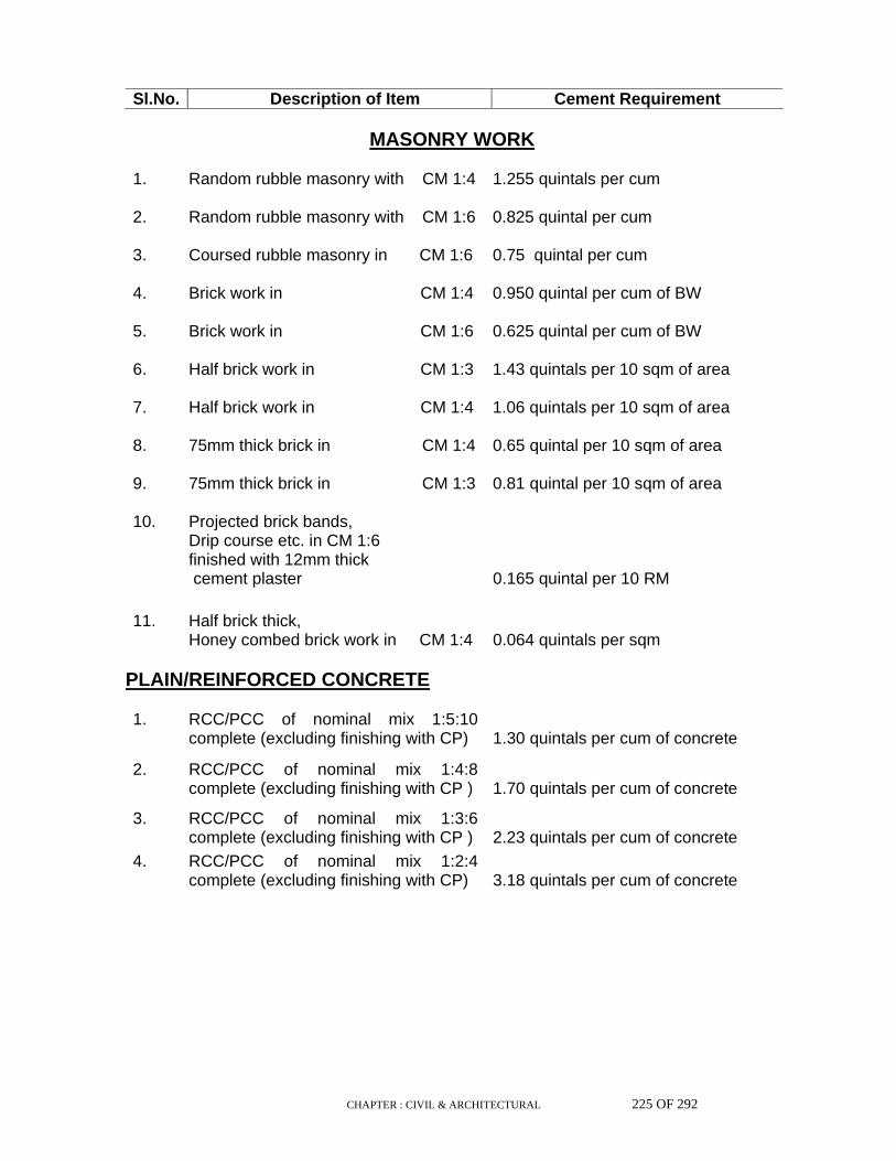
CHAPTER : CIVIL & ARCHITECTURAL 225 OF 292
Sl.No. Description of Item Cement Requirement
MASONRY WORK
1. Random rubble masonry with CM 1:4 1.255 quintals per cum
2. Random rubble masonry with CM 1:6 0.825 quintal per cum
3. Coursed rubble masonry in CM 1:6 0.75 quintal per cum
4. Brick work in CM 1:4 0.950 quintal per cum of BW
5. Brick work in CM 1:6 0.625 quintal per cum of BW
6. Half brick work in CM 1:3 1.43 quintals per 10 sqm of area
7. Half brick work in CM 1:4 1.06 quintals per 10 sqm of area
8. 75mm thick brick in CM 1:4 0.65 quintal per 10 sqm of area
9. 75mm thick brick in CM 1:3 0.81 quintal per 10 sqm of area
10. Projected brick bands, Drip course etc. in CM 1:6 finished with 12mm thick cement plaster
0.165 quintal per 10 RM
11. Half brick thick, Honey combed brick work in CM 1:4
0.064 quintals per sqm
PLAIN/REINFORCED CONCRETE 1. RCC/PCC of nominal mix 1:5:10
complete (excluding finishing with CP) 1.30 quintals per cum of concrete
2. RCC/PCC of nominal mix 1:4:8 complete (excluding finishing with CP )
1.70 quintals per cum of concrete
3. RCC/PCC of nominal mix 1:3:6 complete (excluding finishing with CP )
2.23 quintals per cum of concrete
4. RCC/PCC of nominal mix 1:2:4 complete (excluding finishing with CP)
3.18 quintals per cum of concrete
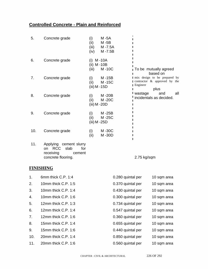
CHAPTER : CIVIL & ARCHITECTURAL 226 OF 292
Controlled Concrete - Plain and Reinforced 5. Concrete grade (i) M -5A
(ii) M -5B (iii) M -7.5A (iv) M -7.5B
6. Concrete grade (i) M -10A (ii) M -10B (iii) M -10C
7. Concrete grade (i) M -15B (ii) M -15C (iii) M -15D
8. Concrete grade (i) M -20B (ii) M -20C (iii) M -20D
9. Concrete grade (i) M -25B (ii) M -25C (iii) M -25D
10. Concrete grade (i) M -30C (ii) M -30D
To be mutually agreed
based on mix design to be prepared by contractor & approved by the Engineer
plus wastage and all incidentals as decided.
11. Applying cement slurry on RCC slab for receiving cement concrete flooring.
2.75 kg/sqm
FINISHING 1. 6mm thick C.P. 1:4 0.280 quintal per 10 sqm area
2. 10mm thick C.P. 1:5 0.370 quintal per 10 sqm area
3. 10mm thick C.P. 1:4 0.430 quintal per 10 sqm area
4. 10mm thick C.P. 1:6 0.300 quintal per 10 sqm area
5. 12mm thick C.P. 1:3 0.734 quintal per 10 sqm area
6. 12mm thick C.P. 1:4 0.547 quintal per 10 sqm area
7. 12mm thick C.P. 1:6 0.360 quintal per 10 sqm area
8. 15mm thick C.P. 1:4 0.655 quintal per 10 sqm area
9. 15mm thick C.P. 1:6 0.440 quintal per 10 sqm area
10. 20mm thick C.P. 1:4 0.850 quintal per 10 sqm area
11. 20mm thick C.P. 1:6 0.560 quintal per 10 sqm area

CHAPTER : CIVIL & ARCHITECTURAL 227 OF 292
12. 12mm thick bearing plaster in CM 1:4 with neat cement finish
0.590 quintal per 10 sqm area
13. Neat cement punning 0.200 quintal per 10 sqm area
14. Flush or ruled or cut or weather pointing on brick work with CM 1:3
0.155 quintal per 10 sqm area
15 Flush or ruled or cut out or weather pointing on brick work with CM 1:2
0.200 quintal per 10 sqm area
16. Raised and cut pointing on brick work with cement mortar 1:3
0.235 quintal per 10 sqm area
17. Flush or ruled pointing on brick flooring with cement mortar 1:4
0.075 quintal per 10 sqm area
18. Flush or ruled pointing on brick flooring with cement mortar 1:6
0.050 quintal per 10 sqm area
FLOORING
1. Brick on edge flooring in cement mortar 1:4
1.100 quintal per
10 sqm area
2. Brick on edge flooring in cement mortar 1:6
0.800 quintal per
10 sqm area
3. 25mm thick (IPS) cement concrete flooring 1:2:4 (1 cement : 2 sand : 4 graded stone chips 12mm nominal size) finished with a floating coat of neat cement.
1.020 quintal per
10 sqm area
4. 40mm thick (IPS) cement concrete flooring 1:2:4 with 20mm and down stone chips finished with a floating coat of neat cement.
1.500 quintal per
10 sqm area
5. 25mm thick (IPS) flooring with base coat 19mm thick 1:2:4 using stone chips 10mm nominal size and 6mm topping coat 1:1 (1 cement : 1 stone chips 3mm size ) with a floating coat of neat cement.
1.370 quintal per
10 sqm area
6. 40mm thick (IPS) flooring with base coat 30mm thick 1:2:4 using stone chips 10mm nominal size and10mm topping coat 1:1 (1 cement : 1 stone chips 3 to 6mm size) with a floating coat of neat cement.
2.320 quintal per
10 sqm area
25mm thick cast-in-situ grey terrazzo
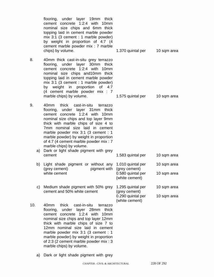
CHAPTER : CIVIL & ARCHITECTURAL 228 OF 292
flooring, under layer 19mm thick cement concrete 1:2:4 with 10mm nominal size chips and 6mm thick topping laid in cement marble powder mix 3:1 (3 cement : 1 marble powder) by weight in proportion of 4:7 (4 cement marble powder mix : 7 marble chips) by volume.
1.370 quintal per
10 sqm area
8. 40mm thick cast-in-situ grey terrazzo flooring, under layer 30mm thick cement concrete 1:2:4 with 10mm nominal size chips and10mm thick topping laid in cement marble powder mix 3:1 (3 cement : 1 marble powder) by weight in proportion of 4:7 (4 cement marble powder mix : 7 marble chips) by volume.
1.575 quintal per
10 sqm area
9. 40mm thick cast-in-situ terrazzo flooring, under layer 31mm thick cement concrete 1:2:4 with 10mm nominal size chips and top layer 9mm thick with marble chips of size 4 to 7mm nominal size laid in cement marble powder mix 3:1 (3 cement : 1 marble powder) by weight in proportion of 4:7 (4 cement marble powder mix : 7 marble chips) by volume.
a) Dark or light shade pigment with grey cement
1.583 quintal per
10 sqm area
b) Light shade pigment or without any (grey cement) pigment with white cement
1.010 quintal per (grey cement) 0.580 quintal per (white cement)
10 sqm area 10 sqm area
c) Medium shade pigment with 50% grey cement and 50% white cement
1.295 quintal per (grey cement) 0.290 quintal per (white cement)
10 sqm area 10 sqm area
10. 40mm thick cast-in-situ terrazzo flooring, under layer 28mm thick cement concrete 1:2:4 with 10mm nominal size chips and top layer 12mm thick with marble chips of size 7 to 12mm nominal size laid in cement marble powder mix 3:1 (3 cement : 1 marble powder) by weight in proportion of 2:3 (2 cement marble powder mix : 3 marble chips) by volume.
a) Dark or light shade pigment with grey
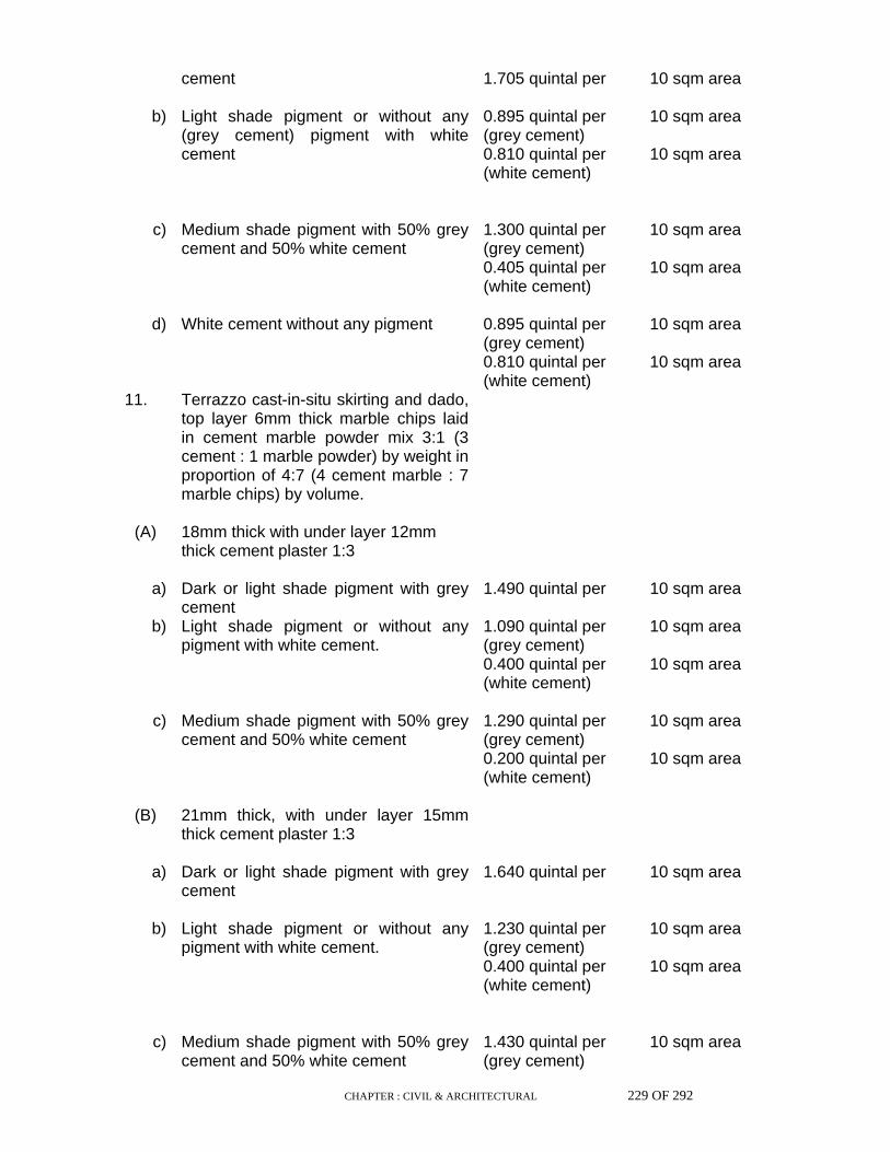
CHAPTER : CIVIL & ARCHITECTURAL 229 OF 292
cement
1.705 quintal per 10 sqm area
b) Light shade pigment or without any (grey cement) pigment with white cement
0.895 quintal per (grey cement) 0.810 quintal per (white cement)
10 sqm area 10 sqm area
c) Medium shade pigment with 50% grey cement and 50% white cement
1.300 quintal per (grey cement) 0.405 quintal per (white cement)
10 sqm area 10 sqm area
d) White cement without any pigment 0.895 quintal per (grey cement) 0.810 quintal per (white cement)
10 sqm area 10 sqm area
11. Terrazzo cast-in-situ skirting and dado, top layer 6mm thick marble chips laid in cement marble powder mix 3:1 (3 cement : 1 marble powder) by weight in proportion of 4:7 (4 cement marble : 7 marble chips) by volume.
(A) 18mm thick with under layer 12mm thick cement plaster 1:3
a) Dark or light shade pigment with grey cement
1.490 quintal per 10 sqm area
b) Light shade pigment or without any pigment with white cement.
1.090 quintal per (grey cement) 0.400 quintal per (white cement)
10 sqm area 10 sqm area
c) Medium shade pigment with 50% grey cement and 50% white cement
1.290 quintal per (grey cement) 0.200 quintal per (white cement)
10 sqm area 10 sqm area
(B) 21mm thick, with under layer 15mm thick cement plaster 1:3
a) Dark or light shade pigment with grey cement
1.640 quintal per 10 sqm area
b) Light shade pigment or without any pigment with white cement.
1.230 quintal per (grey cement) 0.400 quintal per (white cement)
10 sqm area 10 sqm area
c) Medium shade pigment with 50% grey cement and 50% white cement
1.430 quintal per (grey cement)
10 sqm area

CHAPTER : CIVIL & ARCHITECTURAL 230 OF 292
0.200 quintal per (white cement)
10 sqm area
12. Precast terrazzo tiles 20mm thick with marble chips of sizes upto 6mm laid in 25mm thick bed of lime mortar, jointed with neat cement slurry mixed with pigment
a) Dark shades using grey cement
0.88 quintal per 10 sqm area
b) Light shade using white cement. 0.44 quintal per (grey cement) 0.44 quintal per (white cement)
10 sqm area 10 sqm area
c) Medium shade using 50% grey cement and 50% white cement
0.66 quintal per (grey cement) 0.22 quintal per (white cement)
10 sqm area 10 sqm area
13. Precast terrazzo tiles 20mm thick with marble chips of sizes upto 6mm in skirting or on walls, laid on 12mm thick cement plaster 1:3 jointed with neat cement slurry
a) Dark shades using grey cement 1.395 quintal per
10 sqm area
b) Light shade using white cement. 1.175 quintal per (grey cement) 0.22 quintal per (white cement)
10 sqm area 10 sqm area
c) Medium shade using 50% grey cement and 50% white cement
1.285 quintal per (grey cement) 0.11 quintal per (white cement)
10 sqm area 10 sqm area
14. White glazed tiles 5, 6 or 7 mm thick in flooring, skirting and dado on 12 mm thick cement plaster 1 : 3 in base and joined with white cement, slurry etc.
0.942 quintal per (grey cement) 0.25 quintal per (white cement)
10 sqm area 10 sqm area
15. Marble stone slab flooring over 20mm
thick base of lime mortar 1:1:1 (1 lime : 1 surkhi : 1 sand) and jointed with white cement slurry etc.
a) 20 mm thick / 30 mm thick / 40 mm thick
0.075 quintal per (white cement)
10 sqm area
16. Marble stone slab flooring over 20mm thick base of cement mortar 1:4 & jointed with white cement slurry etc.

CHAPTER : CIVIL & ARCHITECTURAL 231 OF 292
a) 20 mm thick 1.275 quintal per (grey cement) 0.075 quintal per (white cement)
10 sqm area 10 sqm area
b) 30 mm thick 1.290 quintal per
(grey cement) 0.075 quintal per (white cement)
10 sqm area 10 sqm area
c) 40 mm thick 1.310 quintal per
(grey cement) 0.075 quintal per (white cement)
10 sqm area 10 sqm area
17. Marble tiles 18 to 24 mm thick in risers of steps, skirting, dado, walls and pillars laid on 12mm thick cement mortar 1:3 (1 cement : 3 sand ) and jointed with white cement slurry
1.16 quintal per (grey cement) 0.075 quintal per (white cement)
10 sqm area 10 sqm area
18. Extra for each additional thickness of 5 mm granolithic layer of 1:2:4 for flooring
0.016 quintal per
10 sqm of area
19 12mm thick cement plaster skirting, dado risers of steps and edges of ground sink with CM 1:3 finished with a floating coat of neat cement.
0.800 quintal per
10 sqm of area
20 15mm thick cement plaster skirting, dado risers of steps and edges of ground sink with CM 1:3 finished with a floating coat of neat cement.
0.995 quintal per
10 sqm of area
21. 19mm thick cement plaster skirting and dado with 12mm thick backing with CM 1:3 and 7mm topping 1:1 (1 cement : 1 stone chips 3mm size) finished with a floating coat of neat cement.
1.35 quintal per
10 sqm of area
22. 25mm thick cement plaster skirting and dado with 18mm thick backing with CM 1:3 and 7mm topping 1:1 (1 cement : 1 stone chips 3mm size) finished with a floating coat of neat cement.
1.85 quintal per
10 sqm of area

CHAPTER : CIVIL & ARCHITECTURAL 232 OF 292
MISCELLANEOUS 1. Marble work for wall lining (Veneer
work) 1.8 to 2.4 cm thick in CM 1:3 including pointing with white cement mortar 1:2 (1 white cement : 2 marble dust)
0.715 quintal per (grey cement) 0.170 quintal per (white cement)
10 sqm of area 10 sqm of area
2. Marble work for wall lining (Veneer work) 4 cm thick in CM 1:3 including pointing with white cement mortar 1:2 (1 white cement : 2 marble dust)
1.020 quintal per (grey cement) 0.170 quintal per (white cement)
10 sqm of area 10 sqm of area
3. Grading roof for water proofing treatment with :-
a) CC 1:2:4 (1 cement : 2 coarse sand : 4
stone aggregate 20mm nominal size) 3.2 quintal per cum of Concrete
b) CM 1:3 5.1 quintal per cum of mortar
c) CM 1:4 3.8 quintal per cum of mortar
4. Providing and fixing MS fan clamps of standard shape and size in existing RCC slab including cutting chase and making good.
0.016 quintal
each
5. Making plinth protection 50mm thick of
CC 1:3:6 (1 cement : 3 sand : 6 graded stone aggregate 20mm nominal size) over 75mm bed of dry brick ballast 40mm nominal size well rammed and consolidated and grouted with fine sand including finishing the top smooth.
1.1 quintal per
10 sqm of area
6. Grouting with
a) CM 1:2 7.18 quintal per cum
b) CM 1:3 5.40 quintal per cum 7. DPC 25mm thick (1:2:4) 0.81 quintal per 10 sqm of area 8. Making plinth protection with bricks on
edge in CM 1:6 over 7.5cm bed of dry brick aggregate 40mm nominal size rammed, consolidated and grouted with fine sand and top of bricks pointed with CM 1:2.
0.86 quintal per
10 sqm of area

CHAPTER : CIVIL & ARCHITECTURAL 233 OF 292
9. Providing and fixing 25mm dia GI pipe
outlet in CM 1:3 including cutting and making good the walls.
0.05 quintal per
10 RM
10. Providing and fixing 40mm dia GI pipe
outlet in CM 1:3 including cutting and making good the walls.
0.075 quintal per
10 RM
11. Providing chases 75mm wide 50mm deep in walls for conduit pipe and filling the same with CC 1:3:6
0.075 quintal per
10 RM
12. Fixing steel windows with 1:2:4 concrete blocks
0.40 quintal per
10 sqm of area
13. Cement-sand mortar :
a) 1:1(1cement :1sand) 10.2 quintals per cum
b) 1:2(1cement : 2sand) 6.8 quintals per cum
c) 1:3(1cement : 3sand) 5.1 quintals per cum
d) 1:4(1cement : 4sand) 3.8 quintals per cum
e) 1:5(1cement : 5sand) 3.1 quintals per cum
f) 1:6(1cement : 6sand) 2.5 quintals per cum
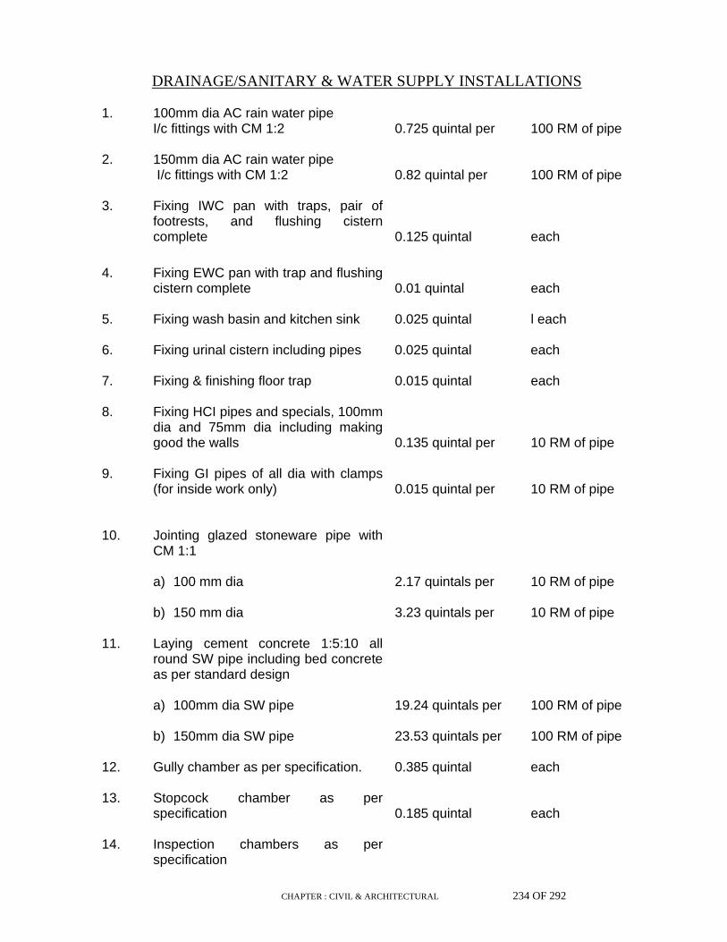
CHAPTER : CIVIL & ARCHITECTURAL 234 OF 292
DRAINAGE/SANITARY & WATER SUPPLY INSTALLATIONS 1. 100mm dia AC rain water pipe
I/c fittings with CM 1:2 0.725 quintal per
100 RM of pipe
2. 150mm dia AC rain water pipe
I/c fittings with CM 1:2 0.82 quintal per
100 RM of pipe
3. Fixing IWC pan with traps, pair of
footrests, and flushing cistern complete
0.125 quintal
each
4. Fixing EWC pan with trap and flushing cistern complete
0.01 quintal
each
5. Fixing wash basin and kitchen sink 0.025 quintal l each 6. Fixing urinal cistern including pipes 0.025 quintal each 7. Fixing & finishing floor trap 0.015 quintal each 8. Fixing HCI pipes and specials, 100mm
dia and 75mm dia including making good the walls
0.135 quintal per
10 RM of pipe
9. Fixing GI pipes of all dia with clamps
(for inside work only) 0.015 quintal per
10 RM of pipe
10. Jointing glazed stoneware pipe with CM 1:1
a) 100 mm dia 2.17 quintals per 10 RM of pipe b) 150 mm dia 3.23 quintals per 10 RM of pipe 11. Laying cement concrete 1:5:10 all
round SW pipe including bed concrete as per standard design
a) 100mm dia SW pipe 19.24 quintals per 100 RM of pipe b) 150mm dia SW pipe 23.53 quintals per 100 RM of pipe 12. Gully chamber as per specification. 0.385 quintal each 13. Stopcock chamber as per
specification 0.185 quintal
each
14. Inspection chambers as per
specification
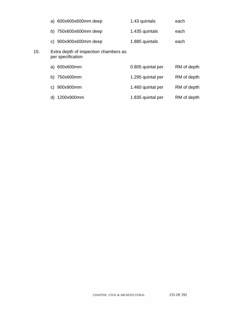
CHAPTER : CIVIL & ARCHITECTURAL 235 OF 292
a) 600x600x600mm deep 1.43 quintals each b) 750x600x600mm deep 1.435 quintals each c) 900x900x600mm deep 1.885 quintals each 15. Extra depth of inspection chambers as
per specification
a) 600x600mm 0.805 quintal per RM of depth b) 750x600mm 1.295 quintal per RM of depth c) 900x900mm 1.460 quintal per RM of depth d) 1200x900mm 1.835 quintal per RM of depth
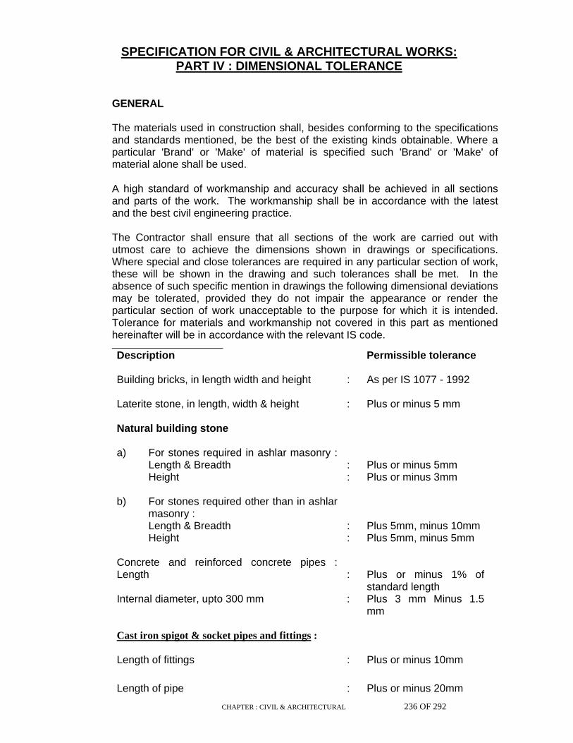
CHAPTER : CIVIL & ARCHITECTURAL 236 OF 292
SPECIFICATION FOR CIVIL & ARCHITECTURAL WORKS:
PART IV : DIMENSIONAL TOLERANCE
GENERAL
The materials used in construction shall, besides conforming to the specifications and standards mentioned, be the best of the existing kinds obtainable. Where a particular 'Brand' or 'Make' of material is specified such 'Brand' or 'Make' of material alone shall be used. A high standard of workmanship and accuracy shall be achieved in all sections and parts of the work. The workmanship shall be in accordance with the latest and the best civil engineering practice. The Contractor shall ensure that all sections of the work are carried out with utmost care to achieve the dimensions shown in drawings or specifications. Where special and close tolerances are required in any particular section of work, these will be shown in the drawing and such tolerances shall be met. In the absence of such specific mention in drawings the following dimensional deviations may be tolerated, provided they do not impair the appearance or render the particular section of work unacceptable to the purpose for which it is intended. Tolerance for materials and workmanship not covered in this part as mentioned hereinafter will be in accordance with the relevant IS code. Description Permissible tolerance Building bricks, in length width and height : As per IS 1077 - 1992 Laterite stone, in length, width & height : Plus or minus 5 mm Natural building stone a) For stones required in ashlar masonry :
Length & Breadth :
Plus or minus 5mm
Height : Plus or minus 3mm b) For stones required other than in ashlar
masonry : Length & Breadth
:
Plus 5mm, minus 10mm
Height : Plus 5mm, minus 5mm Concrete and reinforced concrete pipes : Length
:
Plus or minus 1% of standard length
Internal diameter, upto 300 mm : Plus 3 mm Minus 1.5 mm
Cast iron spigot & socket pipes and fittings :
Length of fittings : Plus or minus 10mm
Length of pipe : Plus or minus 20mm

CHAPTER : CIVIL & ARCHITECTURAL 237 OF 292
Description Permissible tolerance Thickness : minus 1 mm Internal dia of socket : Plus or minus 3 mm Depth of socket : Plus or minus 10mm External dia, upto 75 mm : Plus or minus 3mm 100 mm : Plus or minus 3.5mm 150 mm : Plus or minus 4mm Stoneware pipes, in length upto 75 cm : Plus or minus 10mm Upto 90 cm : Plus or minus 15mm In thickness of barrel and socket not exceeding 450mm
:
Plus or minus 2mm
In thickness of barrel and socket between 500 to 600mm
:
Plus or minus 3mm
Glazed tiles, length of all 4 sides : Plus or minus 0.8mm Individual dimensions and thickness : Plus or minus 0.5 mm Metal doors, windows and ventilators - In overall dimension
:
Plus or minus 1.5 mm
Wooden doors, windows, ventilators Overall dimension of door, window, ventilators
:
Plus or minus 3 mm
All components of shutter except glazing bar Width
:
Plus or minus 3 mm
Thickness : Plus or minus 1 mm Glazing bar, width & thickness : Plus or minus 1 mm
Mild steel tubes, tubulars and other wrought steel fittings a) Thickness
i) butt welded light tubes : Plus not limited minus 8%
medium and heavy tubes : plus not limited minus
10%

CHAPTER : CIVIL & ARCHITECTURAL 238 OF 292
ii) seamless tubes : plus not limited minus
12.5% b) Weight i) single tube (irrespective of the quantity) : + 10% , - 8% ii) for quantity of less than 150m of one
size :
+ 10% , - 8%
iii) for quantity of 150m and over of one
size : + 4% , - 4%
Earth work Finished level of site levelling in hard rock : Plus or minus 50mm Finished level of site levelling except for hard rock
:
Plus or minus 100 mm
Level of pits, trenches foundations : Plus or minus 50mm Concrete & Reinforced concrete Footings, plan dimension : Plus 50 mm Minus 12
mm Eccentricity : 0.02 times the
dimension of footing in the direction limited to 50 mm
Thickness : Plus or minus 0.05 times
the specified thickness Foundations Deviation of planes and lines of their intersection from vertical or inclination along full height
:
Plus or minus 20 mm
Deviation of horizontal plane from horizontal line
for 1 m of the plane in any direction : Plus or minus 5mm for the whole plane : Plus or minus 20mm Sizes of cross section : Plus or minus 8mm Surfaces of inserts to support loads : Plus or minus 5mm Length of elements : Plus or minus 20 mm

CHAPTER : CIVIL & ARCHITECTURAL 239 OF 292
Equipment foundations : Top level of bolt : Plus 20mm Top level of foundation before grouting : Minus 20mm Axes of anchor bolts in plan : Plus or minus 5mm Axis of foundation in either direction : Plus or minus 10mm Deviation in vertical line along height : Plus or minus 10mm Sizes of pits in plan : Plus or minus 20 mm Sizes of steps in plan : minus 20mm Levels of steps, benches and pits : minus 20mm Axes of inserts in plan : Plus or minus 10 mm Basic dimensions in plan : Plus or minus 10mm Deviation of horizontal plan from horizontal line for 1 m of plane in any direction : Plus or minus 5mm for the whole plane : Plus or minus 20mm Local deviations of top surface when checked with a 2 m long straight edge
:
Plus or minus 8mm
Buildings : Surfaces when checked with a 2 m long straight edge
:
Plus or minus 8mm
Sizes of cross section : Plus 8mm Minus 0 mm Length of elements : Plus or minus 20mm Deviation from horizontal plane, for whole building
:
Plus or minus 10mm
Plumb in verticality : 1 in 1000 of height for columns supporting floor beams : Plus or minus 10mm for framed columns linked with crane girders and beams
:
Plus or minus 10mm
Reinforced concrete walls : Length : Plus or minus
20mm

CHAPTER : CIVIL & ARCHITECTURAL 240 OF 292
Flatness of surface when checked with a 2 m long straight edge
:
Plus or minus 8mm
Level of top surface to support assembled elements
:
Plus or minus 5mm
Deviation in planes and lines of intersection from vertical
:
Plus or minus 15mm
Size of cross section : Plus or minus 8mm Placing of reinforcement : Length of bar upto 75 cm long (Other than straight bars)
:
Plus 3 mm Minus 5 mm
75 - 150 cm long : Plus 5 mm Minus 10 mm 150 - 250 cm long : Plus 6 mm Minus 15 mm 250 cm long and above : Plus 7 mm Minus 25 mm Straight bars, all lengths : Plus or minus 25 mm Spacing of bars : Plus or minus 5 mm
Anchor bolts :
Shift in location in plan : Plus or minus 5 mm Same, when bolts are located outside of structural columns
:
Plus or minus 10mm
Top level : Plus 20 mm Threaded length : Plus 30 mm
For Walls For Pillars Masonry Width : Plus or minus 10
mm Plus or minus 10 mm
Shift in axes : Plus or minus 10
mm --- ---
Deviation in row from horizontal line for every 10m length
:
Plus or minus 15 mm
--- ---

CHAPTER : CIVIL & ARCHITECTURAL 241 OF 292
Flatness of surface when checked with a 2 m long straight edge
:
Plus or minus 10 mm
Plus or minus 5 mm
Deviation in lines separating storeys Deviation of surface from vertical and and at angles and corners
:
Plus or minus 15 mm
Plus or minus 15 mm
for 1 storey : Plus or minus 10
mm Plus or minus 10 mm
for whole building : Plus or minus 30
mm Plus or minus 30 mm
Dimensions of openings for doors, windows etc
:
Plus 15 mm Minus 0 mm
Flooring, skirting, dado and plastering
:
Insitu concrete floor : 4 mm Concrete tile and mosaic, in any 3 m length
:
3 mm
in large open area : 15 mm wall tiling - surface should not vary from general plane by more than 1 in 200. Marble and such superior work, in any 2 m length
:
1.5 mm
in any row : 3 mm Plastered surfaces, flatness when checked with a 2 m long straight edge
:
3 mm
Vertical surfaces, upto 1 storey : 5 mm Over full heights : 10 mm Metallic Inserts on assembled components length and width
:
Plus or minus 3 mm
Road work
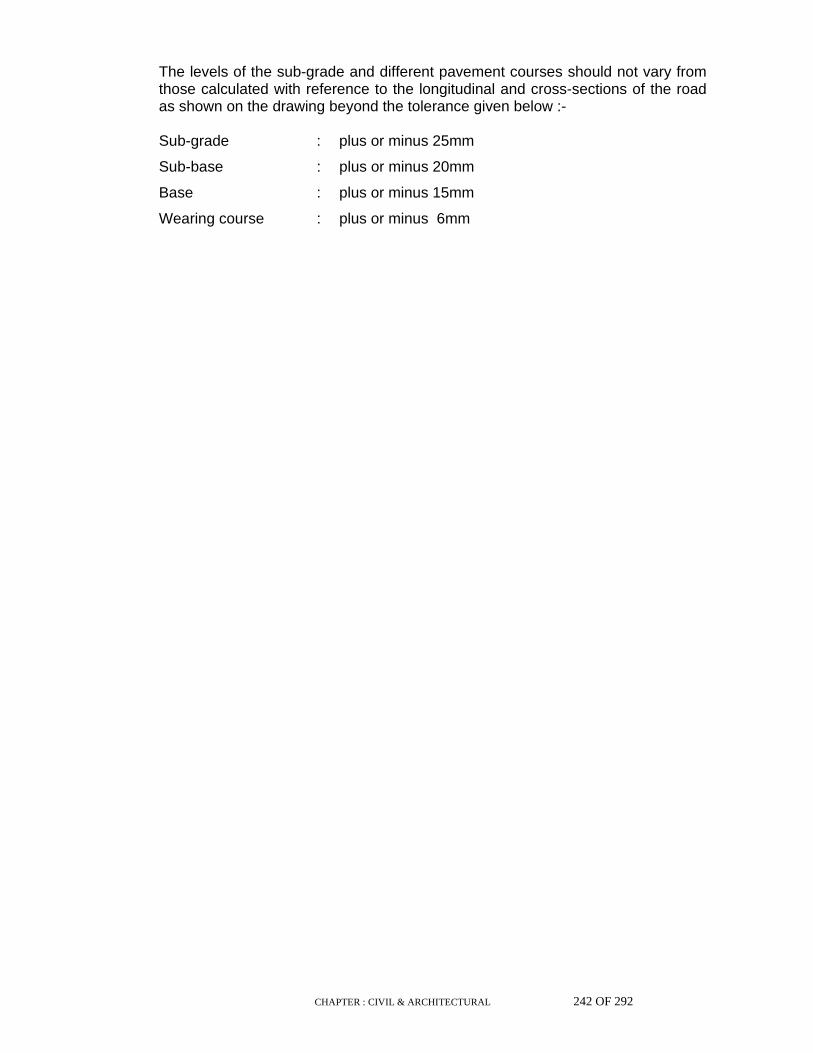
CHAPTER : CIVIL & ARCHITECTURAL 242 OF 292
The levels of the sub-grade and different pavement courses should not vary from those calculated with reference to the longitudinal and cross-sections of the road as shown on the drawing beyond the tolerance given below :-
Sub-grade : plus or minus 25mm
Sub-base : plus or minus 20mm
Base : plus or minus 15mm
Wearing course : plus or minus 6mm
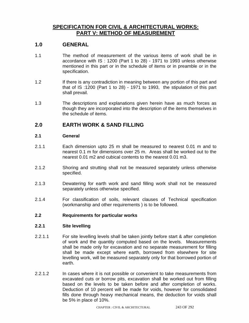
CHAPTER : CIVIL & ARCHITECTURAL 243 OF 292
SPECIFICATION FOR CIVIL & ARCHITECTURAL WORKS: PART V: METHOD OF MEASUREMENT
1.0 GENERAL 1.1 The method of measurement of the various items of work shall be in
accordance with IS : 1200 (Part 1 to 28) - 1971 to 1993 unless otherwise mentioned in this part or in the schedule of items or in preamble or in the specification.
1.2 If there is any contradiction in meaning between any portion of this part and
that of IS :1200 (Part 1 to 28) - 1971 to 1993, the stipulation of this part shall prevail.
1.3 The descriptions and explanations given herein have as much forces as
though they are incorporated into the description of the items themselves in the schedule of items.
2.0 EARTH WORK & SAND FILLING 2.1 General 2.1.1 Each dimension upto 25 m shall be measured to nearest 0.01 m and to
nearest 0.1 m for dimensions over 25 m. Areas shall be worked out to the nearest 0.01 m2 and cubical contents to the nearest 0.01 m3.
2.1.2 Shoring and strutting shall not be measured separately unless otherwise
specified. 2.1.3 Dewatering for earth work and sand filling work shall not be measured
separately unless otherwise specified. 2.1.4 For classification of soils, relevant clauses of Technical specification
(workmanship and other requirements ) is to be followed. 2.2 Requirements for particular works 2.2.1 Site levelling 2.2.1.1 For site levelling levels shall be taken jointly before start & after completion
of work and the quantity computed based on the levels. Measurements shall be made only for excavation and no separate measurement for filling shall be made except where earth, borrowed from elsewhere for site levelling work, will be measured separately only for that borrowed portion of earth.
2.2.1.2 In cases where it is not possible or convenient to take measurements from
excavated cuts or borrow pits, excavation shall be worked out from filling based on the levels to be taken before and after completion of works. Deduction of 10 percent will be made for voids, however for consolidated fills done through heavy mechanical means, the deduction for voids shall be 5% in place of 10%.

CHAPTER : CIVIL & ARCHITECTURAL 244 OF 292
2.2.1.3 In exceptional cases where the quantity is measured on the lorry
measurement, loose stacks, boxes or any other similar method with the approval of the Engineer the deduction for voids shall be 20 per cent from the actual quantity.
2.2.2 Excavation 2.2.2.1 Before commencing excavation of foundations for buildings and structures,
the initial ground levels shall be jointly recorded. The depth of excavation and the calculation of lift shall be based on this. Normally the initial ground level shall be considered as the level of the site as handed over to the contractor. In case excavation is planned and approved to be taken up subsequent to terracing, the terrace level shall be treated as initial ground level.
2.2.2.2 Excavation of foundations, trenches, basements, pits etc., shall be
measured to the dimensions shown in the excavation plan, if any, or of the lowest concrete or masonry course, as the case may be and the actual depth. Working space and slopes shall not be measured.
2.2.2.3 Excavation of rock shall be measured from stacks of excavated rock with a
deduction of 50 per cent for voids or measured in the solid based on levels. 2.2.2.4 In case of following works, no measurement will be recorded for the
excavation beyond drawing / specification.
(a) In work which will be covered externally with damp proof covering. (b) In work which requires formwork.
(c) In work which requires workmen to operate from the outside and for
guniting and post tensioned concrete, ground beams etc. However, if there is a specific provision otherwise in the
item/specification/preamble, for authorised working, it shall be measured accordingly. This working space may be 60 cm. measured from the face of the structure at lowest level, unless otherwise mentioned.

CHAPTER : CIVIL & ARCHITECTURAL 245 OF 292
2.2.2.5 Surface Dressing Trimming of natural ground, excavated surface and filled up area to remove
vegetation and/or small in equalities not exceeding 15 cm deep shall be described as surface dressing and measured in square metres unless otherwise specified in the schedule of items/ preamble.
2.2.2.6 Lead The distance for removal shall be measured over the shortest practicable
route and not necessarily the route actually taken. The description of the item shall include loading and unloading. For the purpose of the measurement of the lead, the area excavated shall
be divided in suitable block and for each block the distance from the centre of the block to the centre of the placed earth pertaining to this block shall be taken as lead.
2.2.3 Back filling/filling 2.2.3.1 In foundations, trenches, basements, pits, etc. and in other like areas, the
measurements shall be the theoretical volume of the filling computed from drawings i.e. the volume measured under excavation minus the volume occupied by the structure and part filling if any, done otherwise.
2.2.3.2 In filling under floors the measurements shall be the theoretical volume as
per drawings after deducting the part filling if any, done otherwise. 2.2.3.3 In embankments, the work shall commence only after recording jointly the
initial ground levels and the measurements shall be made on the basis of finished cross section and initial ground levels. Where controlled compaction by mechanical compaction is done, 5% deduction for voids shall be made. In case controlled compaction by mechanical means is not done then deduction for voids shall be 10%.
2.2.3.4 Filling/Back filling shall not be measured separately for items of excavation,
where filling/back-filling is a part of the composite item and as such is included in excavation item itself.
3.0 ANTI-TERMITE TREATMENT Measurement shall be the plinth area of the ground floor of the building
treated. Dimensions shall be measured to the nearest 0.01 m and area to nearest 0.01 m2.
4.0 CONCRETE (PLAIN & REINFORCED) 4.1 Concrete
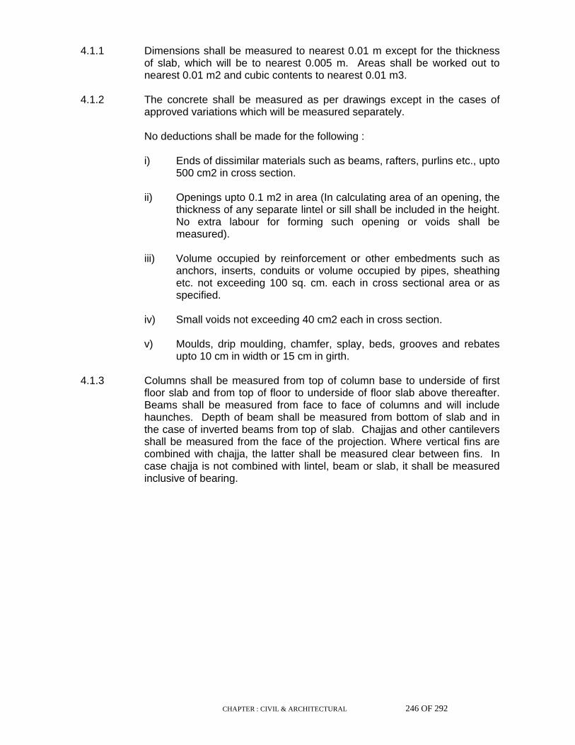
CHAPTER : CIVIL & ARCHITECTURAL 246 OF 292
4.1.1 Dimensions shall be measured to nearest 0.01 m except for the thickness
of slab, which will be to nearest 0.005 m. Areas shall be worked out to nearest 0.01 m2 and cubic contents to nearest 0.01 m3.
4.1.2 The concrete shall be measured as per drawings except in the cases of
approved variations which will be measured separately. No deductions shall be made for the following :
i) Ends of dissimilar materials such as beams, rafters, purlins etc., upto 500 cm2 in cross section.
ii) Openings upto 0.1 m2 in area (In calculating area of an opening, the
thickness of any separate lintel or sill shall be included in the height. No extra labour for forming such opening or voids shall be measured).
iii) Volume occupied by reinforcement or other embedments such as
anchors, inserts, conduits or volume occupied by pipes, sheathing etc. not exceeding 100 sq. cm. each in cross sectional area or as specified.
iv) Small voids not exceeding 40 cm2 each in cross section. v) Moulds, drip moulding, chamfer, splay, beds, grooves and rebates
upto 10 cm in width or 15 cm in girth. 4.1.3 Columns shall be measured from top of column base to underside of first
floor slab and from top of floor to underside of floor slab above thereafter. Beams shall be measured from face to face of columns and will include haunches. Depth of beam shall be measured from bottom of slab and in the case of inverted beams from top of slab. Chajjas and other cantilevers shall be measured from the face of the projection. Where vertical fins are combined with chajja, the latter shall be measured clear between fins. In case chajja is not combined with lintel, beam or slab, it shall be measured inclusive of bearing.
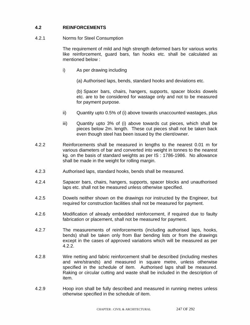
CHAPTER : CIVIL & ARCHITECTURAL 247 OF 292
4.2 REINFORCEMENTS 4.2.1 Norms for Steel Consumption The requirement of mild and high strength deformed bars for various works
like reinforcement, guard bars, fan hooks etc. shall be calculated as mentioned below :
i) As per drawing including (a) Authorised laps, bends, standard hooks and deviations etc. (b) Spacer bars, chairs, hangers, supports, spacer blocks dowels
etc. are to be considered for wastage only and not to be measured for payment purpose.
ii) Quantity upto 0.5% of (i) above towards unaccounted wastages, plus iii) Quantity upto 3% of (i) above towards cut pieces, which shall be
pieces below 2m. length. These cut pieces shall not be taken back even though steel has been issued by the client/owner.
4.2.2 Reinforcements shall be measured in lengths to the nearest 0.01 m for
various diameters of bar and converted into weight in tonnes to the nearest kg. on the basis of standard weights as per IS : 1786-1986. No allowance shall be made in the weight for rolling margin.
4.2.3 Authorised laps, standard hooks, bends shall be measured. 4.2.4 Sapacer bars, chairs, hangers, supports, spacer blocks and unauthorised
laps etc. shall not be measured unless otherwise specified. 4.2.5 Dowels neither shown on the drawings nor instructed by the Engineer, but
required for construction facilities shall not be measured for payment. 4.2.6 Modification of already embedded reinforcement, if required due to faulty
fabrication or placement, shall not be measured for payment. 4.2.7 The measurements of reinforcements (including authorised laps, hooks,
bends) shall be taken only from Bar bending lists or from the drawings except in the cases of approved variations which will be measured as per 4.2.2.
4.2.8 Wire netting and fabric reinforcement shall be described (including meshes
and wire/strands) and measured in square metre, unless otherwise specified in the schedule of item. Authorised laps shall be measured. Raking or circular cutting and waste shall be included in the description of item.
4.2.9 Hoop iron shall be fully described and measured in running metres unless
otherwise specified in the schedule of item.
CHAPTER : CIVIL & ARCHITECTURAL 248 OF 292
4.2.10 Binding wire for the reinforcement shall not be measured separately and
shall be included in the item of reinforcement. 4.3 ADMIXTURE Admixture will be measured separately as specified or on the basis of the
requirement as approved by the Engineer. 4.4 FORMWORK Each dimension shall be measured to the nearest 0.01 m and area to the
nearest 0.01 sq.m. 4.4.1 Formwork shall be measured as the actual surface in contact with concrete
and paid in sq.m. unless included in the rate for concrete in specific item of work.
4.4.2 All the measurements shall be computed from the drawings except in the
cases of approved variations which will be measured separately. 4.4.3 Formwork shall not be measured separately for precast concrete work,
grouting and damp proof course which shall be included in the concrete rates.
4.4.4 No measurement for formwork in construction joints shall be made. 4.4.5 Openings upto 0.1 sq.m. shall be neglected, as if non - existent, for the
purpose of formwork measurement. 4.4.6 No extra measurement or payment shall be made for making the form work
water proof or for supports, scaffolding, staging, centering, approaches etc. 4.4.7 No measurement shall be taken for the formwork in pockets, openings,
chambers, chases etc., in concrete if the cross sectional area is less than or equal to 0.1 sq.m. in each case. If the cross section area of any opening exceeds 0.1 sq.m. the actual area of the formwork shall be measured for payment.
4.5 EMBEDDED PARTS 4.5.1 These shall be measured on the basis of standard theoretical weight of the
complete insert according to the drawing/direction. 4.5.2 Embedded steel, which are the integral parts of the embedment according
to drawing and are required for anchoring the embedded parts in concrete shall be measured on the basis of the theoretical standard weight. In case of anchor bolts the theoretical weights of the nuts, lock nuts, check nuts and washers shall be added in the measurement for payment.
4.5.3 All bye-works such as jigs, fixtures, templates and other arrangements
which are not integral parts of the embedded parts, but necessary to secure those (embedded parts) in position shall not be measured for payment.

CHAPTER : CIVIL & ARCHITECTURAL 249 OF 292
4.5.4 Anti-corrosive paint over the exposed surfaces and protection of the anchor
bolts with grease tc., shall not be measured for payment. 4.5.5 Modification works necessary to rectify the mistake of already placed
embedded parts shall not be measured. 4.6 GROUTING 4.6.1 Grouting shall be measured in volume except in the cases of grouting by
special cement compound or epoxy compound which will be measured by number.
4.6.2 Measurement shall be computed from the drawings except in the cases of
approved variations which shall be measured separately and subsequently added to or deducted from.
4.6.3 Necessary formwork shall not be measured for payment. 4.7 DAMP PROOF COARSE 4.7.1 Measurement shall be in sq.m. stating thickness and computed from the
drawings except in the cases of approved variations which will be measured separately.
4.7.2 Necessary formwork shall not be measured for payment. 5.0 MASONRY 5.1 Dimensions shall be measured to nearest 0.01 m, areas to nearest 0.01 m2
and cubic contents to nearest 0.01 m3. 5.2 No deduction shall be made for :
(i) Ends of dissimilar materials such as joints, beams, posts, girders, trusses, lintels, purlins etc., upto 0.1 m2 in section.
ii) Openings upto 0.1 m2 in area. (iii) Wall plates, bed plates, bearing of slab etc., thickness not exceeding
10 cm. and bearing not extending over the full thickness of wall. (iv) Cement concrete blocks for holdfasts and the like. (v) Iron fixtures such as pipes etc. upto 300 mm. dia. and hold fasts for
doors and windows. 5.3 Dressed stonework such as in sills, cornices , column caps, copings etc.,
shall be measured as the smallest rectangular block from which the finished stone can be worked.
5.4 Honeycomb openings shall not be deducted from the area of honeycomb
brickwork.

CHAPTER : CIVIL & ARCHITECTURAL 250 OF 292
5.5 Brickwork of full brick width or more shall be measured in cu.m. while of
thickness of half brick or less shall be measured in sq.m., unless otherwise specified.
5.6 Reinforcements for reinforced brick work shall be measured separately,
unless otherwise specified and no deduction for reinforcement shall be made from brickwork.
6.0 PLASTERING & POINTING 6.1 All plastering and pointing shall be measured in sq.m. unless otherwise
described. Dimensions shall be measured to nearest 0.01 m and areas to 0.1 sq.m.
6.2 Ceiling shall be measured between walls or partitions (dimensions before
plastering) shall be taken. Measurement of wall plastering shall be taken between walls or partitions for length (dimension before plastering) and from top of floor or skirting to ceiling for height.
6.3 The methods of measurement including the deductions for openings etc.,
shall be according to the relevant part of IS : 1200 (Part 1 to 28) - 1971 to 1993.
7.0 WHITE WASHING, COLOUR WASHING, PAINTING & OTHER
FINISHES. The method of measurement shall be according to the relevant part of IS : 1200 (Part 13 & 15) - 1987. 8.0 FLOORING, PAVING & FACING WORKS 8.1 The work shall be measured as a complete finished item including
necessary underbed, adhesives, dividing strips, joint sealing and necessary grinding, polishing and finishing where specified. The subgrade or the base course shall be measured separately against respective item unless otherwise specified.
8.2 All works shall be measured net, dimensions being measured to nearest
0.01 m and areas to nearest 0.01 sq.m. Any opening less than 0.1 sq.m. in area shall not be deducted nor any extra payment made for that.
8.3 Building paper or water proofing by bituminous felts/mastic asphalt
treatment, where specified to be laid below floor, shall be measured separately for payment unless otherwise specified.
8.4 Laps and seams in sheet finishing (linoleum, cork, PVC, rubber & like) shall
be deemed to be included in the item itself even if not described explicitly and shall not be measured and paid separately.
9.0 WOODWORK
CHAPTER : CIVIL & ARCHITECTURAL 251 OF 292
9.1 All work shall be measured net for finished dimensions as fixed, that is no
extra measurement or allowance shall be made for shape, joints, wastage etc. subject to specific provision made in the IS : 1200 (Part 21) - 1973 and for dimensions supplied beyond those specified in the drawing.
9.2 Wooden frame rought, finished and fixed shall be measured net for overall length nearest
to 0.01 m, width and thickness to the nearest 2mm or as specified in the drawing and cubic contents calculated in cubic metres to the nearest three places of decimals.
Wooden shutters of all types Length and width of the shutters shall be measured net as fixed to the
nearest cm. in closed position covering the rebates of the frame but excluding the gap between the shutter and the floor and the area calculated in square metre upto two places of decimal.
Over lap of two leaves of shutter shall not be measured separately.

CHAPTER : CIVIL & ARCHITECTURAL 252 OF 292
Hand rails Hand rails of finished width and depth as specified in the item shall be
measured in running metres upto two places of decimal. 9.3 Painting and polishing, unless otherwise described in the schedule of
items, shall be measured separately for payment. 9.4 Builder's hardware and fittings for doors windows and ventilators shall be
measured separately, unless stated otherwise in the Schedule of Items. Hardware and fittings shall be measured according to IS : 1200 (Part-VII) - 1972.
9.5 Hold fasts for door, window and ventilator frames shall be measured
separately. 9.6 Timber Partitions This shall be measured in area calculated in sq. m. to the nearest two
places of decimal. 9.7 Glazed shutters and glazed partitions (Wooden) Glazed shutters/glazed partitions with wooden frames shall be measured
as a single item in area calculated in sq.m. to the nearest two places of decimal. No separate measurement for glazing/glass panes shall be made.
9.8 Provision of making holes/opening/chases in masonry/ concrete flooring
etc. for fixing and making good of the same shall not be measured separately for payment.
9.9 Bitumen painting or approved wood preservative of the timber surfaces in
contact with masonry/concrete floor etc. shall not be measured for payment.
10.0 METAL DOORS, WINDOWS & VENTILATORS 10.1 Door, window and ventilator/louvers as fixed, shall be measured net as
clear width between jambs and clear height between floor/sill and underside of lintel, but excluding the gap between door shutters and floor. Dimensions shall be calculated to the nearest 0.01 m., area calculated in sq.m. upto two places of decimal.
10.2 For MS collapsible shutter/gate, rolling shutter sliding folding door, length
and breadth shall be measured to the nearest cm. for the clear area of opening as per drawing in which they are installed and calculated in sq.m. to the nearest two places of decimal.
10.3 M.S. Rolling grills, doors of steel plate, sliding door louvered ventilators,
gates, grills, as fixed, shall be measured and computed to weight from the size as per drawing unless otherwise specified.
CHAPTER : CIVIL & ARCHITECTURAL 253 OF 292
10.4 Glazed doors, windows, louvers, partitions (both steel and aluminium) shall
be measured in sq.m. to the nearest two places of decimal. No separate measurement for glazing/glass panes shall be made for payment.
11.0 GLAZING 11.1 Glazing shall not be separately measured for doors, windows and
ventilators unless otherwise specified. 11.2 North light and roof glazing shall be paid as the area from outside to
outside of glazing including frames, to the nearest 0.01 sq.m. 11.3 Glazing, where shown in the schedule of items as a separate item, shall be
measured from edge to edge of glass as fixed. 12.0 WATER SUPPLY, DRAINAGE, SEWERAGE & SANITATIONS 12.1 All the pipelines buried under soil/masonry/floors/ concrete, laid
over/underground/along masonry/along under floor shall be measured in metres along the centreline together with fittings/specials upto two places of decimal against respective schedule of items for different diameter (the diameter as specified shall mean nominal bore except PVC pipe) unless otherwise specified.
12.2 All necessary earth work in trenches for laying pipe lines including
dewatering, levelling and trimming to the gradient, sand filling in the trenches before laying the pipe, back filling either by sand or by approved borrowed soil after laying the pipe lines including necessary compaction by spraying water and levelling/dressing the same shall not be measured separately for payment unless otherwise specified.
12.3 All required specials, i.e. bends tees, shoes cowls, plug, elbows, unions,
caps, checkout and the like excluding valves shall not be measured separately for payment unless otherwise specified.
12.4 All fixing and supporting arrangement of the pipes like the supports,
saddles, brackets, clamps, cleats, covering the pipes with concrete in case of pipes laid over ground, special arrangement for supporting the pipe like while coming out from the building to the trenches etc. shall not be measured separately for payment, unless otherwise specified.
12.5 All the arrangement in road crossing like cutting the road, diverting the road
and drains, concealing the pipes with suitable approved measures, backfilling the area, covering and making good of the road with similar materials/design shall not be measured separately for payment, unless otherwise specified.
12.6 Septic tanks, inspection pits, manholes etc., shall be considered as a
composite single item including excavation, dewatering, concrete, masonry, back filling, protection of other service lines and all the like works unless otherwise specified.

CHAPTER : CIVIL & ARCHITECTURAL 254 OF 292
12.7 All the valves and all the bathroom/W.C./Kitchen fixures like bib tap, stop
cock, shower, all sanitary wares, towel rails, mirrors etc., shall be measured separately under respective item in the schedule, unless otherwise specified.
13.0 WATER PROOFING, DAMP PROOFING 13.1 Water proofing for roofs 13.1.1 Length and breadth shall be measured in metre upto two places of decimal
and area calculated in sq.m. upto two places of decimal. 13.1.2 Measurement shall be made for the net covered area. No measurement
shall be made for overlapping for end and side joints and for bends around/along the corners, ends and for special treatment around pipes, rain water gulleys, steel structure and the like etc. No deduction shall be made in the measurement for the opening of area less than 0.1 m2 each and no extra payment shall also be made for any special works made around such openings.
13.1.3 Water proofing treatment shall be considered as a single composite item
including priming painting coat, water proofing felts, binding bituminous coats, top bituminous coat and pea size gravel or sand finishing etc.
13.1.4 For lime concrete terracing the consolidated thickness shall be considered
for measurement.

CHAPTER : CIVIL & ARCHITECTURAL 255 OF 292
13.2 For Water proofing treatment in basement 13.2.1 With bituminous felts 13.2.1.1 Length and breadth shall be measured in metre upto two places of decimal
and area calculated in sq.m. utp two places of decimal. 13.2.1.2 Measurement shall be made for the net covered area. Measurement shall
be made from the drawing, except in certain special cases where it is impossible to compute from drawing and the measurement shall be made as executed. No measurement shall be made for overlaps, special measures around projected pipes, sealing the bends/rounds and in other cases, necessary projection/ overlap for the connection between vertical and horizontal junction etc.
13.2.1.3 Water proofing treatment shall be considered as a single composite item,
including priming painting coat, water proofing felts, binding bituminous coats and top bituminous coat etc.
13.3 Mastic Treatment 13.3.1 Length and breadth shall be measured in metres upto two places of
decimal and area calculated in sq.m. upto two places of decimal. 13.3.2 Measurement shall be made for the net covered area. No deduction in
measurement shall be made for opening of area upto 0.1 sq.m. each and no extra payment shall be made for any special treatment around such openings. No measurement shall be made for extra payment for the special works necessary for junctions, corners, roundings, bends for the works around pipes and the like.
14.0 CEILING & LININGS 14.1 Dimensions shall be measured to the nearest 0.01 m., areas to be worked
out to the nearest 0.01 sq.m. 14.2 Work formed to circular surfaces shall be measured separately unless
otherwise specified. 14.3 All work unless otherwise described shall be measured as flat in sq.m. 14.4 No deduction in measurement shall be made for openings not exceeding
0.4 sq.m. and no extra measurement shall be made for forming such openings.
CHAPTER : CIVIL & ARCHITECTURAL 256 OF 292
15.0 ROAD WORK 15.1 Dimensions shall be measured to nearest 0.01 m. Where the thickness is
less than 20 cm., it shall be measured to nearest 0.005 m. Areas shall be worked out to nearest 0.01 sq.m. and cubic contents to the nearest 0.01 cu.m.
15.2 Where thickness is measured, it shall be the minimum thickness after
compaction. 15.3 Cement concrete bases and roads shall be measured either in sq.m. or
cu.m. as specified. 15.4 Unless otherwise specified, expansion and dummy joints shall be described
and measured separately and given in running metres stating the thickness and depth of the joints.

CHAPTER : CIVIL & ARCHITECTURAL 257 OF 292
SPECIFICATION FOR CIVIL & ARCHITECTURAL WORKS: PART VI : SAFETY REQUIREMENT FOR CONSTRUCTION WORKS
1.0 GENERAL
This specification deals with the subject matter of safety and protection to be observed in the Civil Construction. This shall be followed along with all related statutory requirements/obligation including Governmental byelaws, codes, ordinance of local or central authorities related to the construction work. In case of complicated work like deep excavation, intricate shuttering and formwork, excavation in loose soil and below water table, stacking of excavated earth etc., work plan with necessary drawings and documents have to be prepared by the Contractor and got approved by the Engineer. Necessary reference shall be made to the following Indian Standard Codes on safety requirements for various type of work :
Indian Standard 4081 - 1986 Blasting & Drilling.
5916 - 1970 Construction with Hot Bituminous Materials.
4130 - 1991 Demolition of Buildings.
3764 - 1992 Excavation Work
5121 - 1969 Piling & Other Deep Foundations.
4014 - (P-II) - 1967 Scaffolding, Steel Tubular.
3696 - (P-I & P-II) Scaffolds and Ladders.
1987 to 1991
6922 - 1973 Structures Subject to Underground Blasts.
4756 - 1978 Tunneling Work.
5499 - 1969 Underground Air-raid Shelters in Natural Soil.
4138 - 1977 Working in Compressed Air.
7293 - 1974 Working with Construction Machinery
8989 - 1978 Erection of Concrete Framed Structures.
2.0 BLASTING
CHAPTER : CIVIL & ARCHITECTURAL 258 OF 292
2.1 Detonators and other explosive for blasting shall be taken to the blasting
area in the original container or any separate non-metal container. This shall not be carried loose or mixed with other materials. Detonators and explosives must be kept separately.
2.2 No shot for blasting shall be fired except by persons licensed to do so. 2.3 Drilling shall not be resumed after a blast has been fired unless a thorough
examination has been made to make sure that there is no unexploded charge.
2.4 Before firing a shot, sufficient warnings by means of whistling and/or
otherwise shall be given to get men off the danger area. Blasting areas shall be cordoned off & red flags during day time and red lights during night time displayed prominently marking off the cordoned area.
2.5 All people except those who have actually to light the fuses must be
removed to a safe distance of not less than 200 metres as a rule. 2.6 Wherever possible, blasting mats should be used. 2.7 Contractors doing blasting work must have licence and an approved
magazine to store explosives. 2.8 Blasting operations shall be carried out during fixed hours of the day which
shall be notified in writing. 2.9 Provisions in explosives Rules 1940 as amended from time to time, Indian
Explosives Act 1844 (IV of 1884), and others shall be strictly followed. 3.0 EXCAVATIONS 3.1 Sides of all excavations must be sloped to a safe angle, not steeper than
the angle of repose of the particular soil. If it is not possible to give a proper slope, the sides of the excavation where there is a danger of fall or dislodgement of earth or any material, shall be securely supported by timber or other type of shoring.
3.2 No excavation or earth work below the foundation level of an adjoining
building shall be taken up unless adequate steps are taken to prevent damage to the existing structure or fall of any part.
3.3 Every accessible part of an excavation, pit or opening in the ground into
which there is a danger of persons falling shall be suitably fenced with a barrier upto a height of one metre suitably placed from the edge of the excavation as far as practicable.
3.4 No material or load shall be placed or stacked near the edge of the
excavation or opening in the ground. The excavated material shall not be placed within 1.5 m of the trench or half of the depth of the trench whichever is more.
CHAPTER : CIVIL & ARCHITECTURAL 259 OF 292
3.5 Cutting shall be done from top to bottom. No undercutting of sides of
excavation shall be allowed. 3.6 All narrow trenches 1.2 m or more depth, shall at all times be supplied with
atleast one ladder for each 30m in length or fraction thereof. Ladder shall be extended from bottom of the trench to atleast one metre above the surface of the ground. The side of the trenches which are 1.5 m or more in depth shall be stepped back to give suitable slope, or securely held by planking, strutting and bracing so as to avoid the danger of side collapse.
3.7 Materials shall not be dumped against existing walls or partition to a height
that may endanger the stability of the walls. 3.8 While withdrawing piled materials like loose earth, crushed stone, sand,
etc., from the stock piles, no over hanging shall be allowed to be formed in the existing dump.
3.9 No material on any of the sites of work shall be so stacked or placed as to
cause danger or inconvenience to any person or public or any other agency at work.
4.0 DEMOLITION 4.1 On every demolition job, danger signs shall be conspicuously posted all
round the structure and all doors, openings giving access to the structure shall be kept barricaded or marked except during the actual passage of workmen or equipment. However, provision shall be made for at least two independent exits for escape of workmen during any emergency.
4.2 During night, red lights shall be placed on or about all the barricades. 4.3 Where in any work of demolition it is imperative, because of danger existing
to ensure that no unauthorised person shall enter the site of demolition outside working hours, a watchman should be employed. In addition to watching the site he shall also be responsible for maintaining all notices, lights and barricades.
4.4 All the necessary safety appliances as per IS ;4130 shall be issued to the
workers and their use explained. It shall be ensured that the workers are using all the safety appliances while at work.
4.5 The removal of a member may weaken the side wall of an adjoining
structure and to prevent possible damage, these walls shall be supported until such time as permanent protection is provided. In case any danger is anticipated to the adjoining structure the same shall be got vacated to avoid any danger to human life.
4.6 The power on all electrical service lines shall be shut off and all such lines
cut or disconnected at or outside the property line, before the demolition work is started. Prior to cutting of such lines the necessary approval shall be obtained from the electrical authorities concerned. The only exception will be any power line required for demolition work itself.
CHAPTER : CIVIL & ARCHITECTURAL 260 OF 292
4.7 All gas, water, steam and other service lines shall be shut off and capped
or otherwise controlled at or outside the building line, before demolition work is started.
4.8 All the mains and meters of the building shall be removed or protected from
damage. 4.9 If a structure to be demolished has been partially wrecked by fire, explosion
or other catastrophe, the walls and damaged roofs shall be shored or braced suitably.
4.10 Walkways and passage ways shall be provided for the use of the workman
who shall be instructed to use them and all such walkways and passageways shall be kept adequately lighted, free from debris and other materials.
4.11 All nails in any kind of lumber shall be withdrawn, hammered or bent over
as soon as such lumber is removed from the structure being demolished, and placed in piles for future cleaning or burning.
4.12 All the roads and open area adjacent to the work site shall either be closed
or suitably protected. 4.13 No electric cable or apparatus which is liable to be a source of danger or a
cable or apparatus used by the operator shall remain electricity charged. 4.14 All practical steps shall be taken to prevent danger to persons employed
from risk of fire or explosion or flooding. No floor, roof or other part of the building shall be so overloaded with debris or materials as to render it unsafe.
5.0 VEHICLE 5.1 No person shall board any vehicle or equipment when it is in motion. 5.2 Suitable blocks shall be placed against the wheels of a vehicle when it is
used for tipping materials into excavation or a pit or over the edge of any embankment or earthwork to avoid the danger of its running over the edge.
5.3 All workers shall stand clear of the vehicle while it is dumping. If the
material being dumped is very heavy or sticky, dump hooks shall be used or dumper shall be clamped to prevent any danger of its tripping.
5.4 Materials shall not be allowed to be loaded in a vehicle so as to project
horizontally beyond the sides of the body of the vehicle. All materials projecting beyond the front or rear shall be indicated by a red flag in the day and with red light in the night.
5.5 Driver of the truck or any heavy vehicle shall not reverse it unless assisted
by a signal man who shall have a clear view of the driver and the area beyond the truck during reversing operation.
5.6 Maximum speed of a heavy vehicle must not exceed 15 km. per hour.

CHAPTER : CIVIL & ARCHITECTURAL 261 OF 292
6.0 SCAFFOLDING, GANGWAYS, LADDERS & SHUTTERING 6.1 For all work that cannot be done from the ground level or from part of any
permanent structure or from other available means of support, soundly constructed scaffoldings of adequate strength shall be used as a safe means of access to places of work.
6.2 All scaffolding shall be securely supported or suspended and wherever
necessary be properly braced to ensure stability. 6.3 Chains, ropes or other lifting materials used for the suspension of
scaffoldings must be of adequate strength and shall be of tested quality. 6.4 All such chains and ropes used for the suspension of scaffoldings shall be
properly fastened to safe anchorage points. 6.5 The platform of a suspended scaffolding shall be sufficiently wide.
Suspended scaffolding shall have hand rail on 3 sides of about 1.0 m height.
6.6 All working platform and stages from which workers are liable to fall shall
be of adequate width depending on the type of work done and closely boarded and planked.
6.7 Scaffolding or staging more than 3.5 m above the ground or floor,
suspended from an overhead support or erected with stationary support shall have a guard rail properly attached, bolted, braced and otherwise secured atleast 1 m high above the floor or platform of such scaffolding or staging and extending along the entire length of the outside ends thereof with only such opening as may be necessary for the delivery of materials. Such scaffolding or staging shall be so fastened as to prevent it from swaying from the building or structure. The platform shall also be provided with toe boards of atleast 150 mm high so placed as to prevent the fall of materials and tools from there.
6.8 All platforms or gangways, runways and the stairs shall be kept free from
unnecessary obstructions, materials or junk. 6.9 Working platforms, gangways & stairways shall be so constructed that they
shall not sag unduly or unequally, and if the height of the platform or the gangway or the stairway is more than 3.5 m above ground level or floor level they shall be closely boarded, shall be of adequate width and shall be suitably fenced.
6.10 Every opening in the floor of a building or in a working platform shall be
provided with suitable fencing or railing whose minimum height shall be 1 m to prevent the fall of persons or materials.
6.11 Every ladder shall be securely fixed at top and bottom. A ladder more than
5 m long shall have a prop.

CHAPTER : CIVIL & ARCHITECTURAL 262 OF 292
6.12 All ladders used shall be of good construction, sound materials and
adequate strength. Ladders with defective or missing rungs shall not be brought into use. The spacing of rungs shall not exceed 30 cms and these shall be recessed atleast 12 mm into rails.
6.13 All ladders or rungs used for vertical height of more than 10 m shall have
an intermediate landing. All such intermediate landings shall be provided with guard rails to a height of atleast 1 m.
6.14 Every ladder shall be securely placed so that it cannot move either at the
top or at the bottom and it shall rise to a height of atleast 1.2 m above the place of landing.
6.15 No portable single ladder shall be over 8 m in length. 6.16 Spacing between the side rails of the ladder shall not be less than 300 mm
for ladders upto 3 m in length. For longer lengths, this shall be increased at 6 mm for each additional 0.3 m of length.
6.17 Metal ladders must not be used for electrical work or near electric circuit of
equipments. 6.18 All scaffolds, ladders and other safety devices mentioned or described
herein shall be maintained in safe condition and no scaffold, ladder or equipment shall be altered or removed while it is in use.
6.19 Unfinished scaffolding which is under construction shall be prominently marked as unsafe and any access points shall be closed.
6.20 All Planking and Decking on walkways and scaffolds should be adequately
supported at each end of the plank and intermediately if necessary. Planks should not be allowed to cantilever beyond the last support but should be overlapped if necessary on to the next plant.
6.21 Shuttering The above remarks shall be applicable for this also. Shuttering, particularly
for slabs, should be treated as a scaffold. Unfinished shuttering should be marked as dangerous similarly the finished formwork should be adequately supported, care being taken to avoid trap door effects.
7.0 MOBILE LIFTING APPLIANCES 7.1 No mobile lifting appliances shall used on a sloping surface unless
adequate precautions are taken to ensure stability. 7.2 Adequate precautions shall be taken to see that jib of the mobile crane
does not come in contact with overhead electric transmission line. 7.3 Only one person shall give signals to the operator of mobile lifting
appliances.
CHAPTER : CIVIL & ARCHITECTURAL 263 OF 292
7.4 Maximum load to be lifted by lifting appliances shall be marked in a position
where it can be clearly seen by the crane driver and the operator. 7.5 No load shall be raised, lowered or suspended from a chain or rope having
a knot in any of the part. 7.6 No chain which is joined to another chain by means of bolt and nut shall be
used for raising, lowering or suspending any load. 7.7 All chains, ropes and lifting gears shall be carefully examined and tested by
a competent Maintenance Engineer atleast once in every quarter. 7.8 When the work is stopped or when the mobile lifting equipment is not in
operation, the boom must be lowered to the horizontal position and tied securely in place to prevent accidental drop.
7.9 No person shall walk under a load which is swinging by a lifting equipment. Guide rope must be attached to the load to prevent its swinging. 7.10 The foot blocks of the crane before starting work shall be securely
supported and firmly anchored to prevent its movement in any direction. 7.11 Use of Hoisting machines and tackle including their attachments,
anchorage and supports shall conform to the following standards of condition.
7.11.1 These shall be of good mechanical construction, sound material and
adequate strength and free from defect and shall be kept in good working order.
7.11.2 Every rope used in hoisting or lowering materials or as a means of
suspension shall be of durable quality and adequate strength and free from patent defects.
7.11.3 Every crane driver or hoisting appliance operator shall be properly qualified
and no person under the age of 21 years shall be in charge of any hoisting machine or give signals to the operator.
7.11.4 In case of every hoisting machine and every chain ring hook shackle swivel
and pulley block used in hoisting or lowering or as means of suspension the safe working load shall be ascertained by adequate means, every hoisting machine and all gears referred to above shall be plainly marked with the safe working load. In case of hoisting machine having a variable safe working loading, each safe working load of the conditions under which it is applicable shall be clearly indicated. No part of any machine or of any gear referred to above in this paragraph shall be loaded beyond the safe working load except for the purpose of testing. Mobile cranes shall have the working load and the radius of jib for the load marked on it.
7.11.5 The top pulley for hoisting a load shall be opened monthly and the spindle
inspected to see if any undue wear has taken place and for greasing.

CHAPTER : CIVIL & ARCHITECTURAL 264 OF 292
7.11.6 In case of departmental machine, the safe working load shall be notified by
the Engineer concerned. As regards contractor's machines the Contractor shall notify the safe working load of the machine to the Engineer whenever he brings any machinery to site of work and get it verified by the Engineer concerned.
7.12 Motors, gearing, transmission, electric wiring and other dangerous part of
hoisting appliances shall be provided with efficient safeguards. Hoisting appliances shall be provided with such means as will reduce to the minimum, the risk of accidental descent of the load. Adequate precautions shall be taken to reduce to the minimum, risk of any part of a suspended load becoming accidentally displaced.
8.0 RIVETTING, WELDING & GAS CUTTING & STEEL ERECTION 8.1 Rivetting 8.1.1 Bolts covered with wet or slippery compounds shall not be used in
fabricating structural work. 8.1.2 The rivet heater must keep the rivet heating equipment as near as possible
to the place of work. 8.1.3 A pail of water shall always be kept ready for quenching fire when stopping
rivetting work. 8.1.4 Hot rivet shall not be thrown across aisles and shaftways. 8.1.5 Metal buckets for catching hot rivets must have false wooden bottoms to
prevent rivets from rebounding. 8.1.6 All rivets, bolts, nuts, and other tools must be kept in boxes and not left
loose, (For any further safety measures relevant Indian Standards and safety specifications of structural section shall be referred to).
8.2 Welding & Gas Cutting 8.2.1 All cylinders must be used and stored in upright position only. 8.2.2 Cylinders must be stored away from open flames and other source of heat. 8.2.3 Oxygen cylinders must not be stored near other cylinders containing gas or
oil, grease or other combustible materials. 8.2.4 While the cylinder is in use, the cylinder valve key or wrench must be
placed on the valve spindle. 8.2.5 Before a cylinder is moved, the cylinder valve must be closed. 8.2.6 Gas cutting torches must be lighted by means of friction flames or similar
other methods and not with matches.

CHAPTER : CIVIL & ARCHITECTURAL 265 OF 292
8.2.7 When torches are being changed or welding stopped for some time valves
for all cylinders must be closed. 8.2.8 The coloured lenses used for welding or gas cutting must be of proper
shade for the work being done. 8.2.9 Suitable eye protection equipment such as goggles, hand shields etc., must
be used by persons engaged in welding or gas cutting operations. 8.2.10 Before any heavy structural member is gas cut, make sure that it is cleared
and supported by ropes, cables, chains or any other means to prevent its dropping or swinging.
8.2.11 Cylinder valves and connections are not to be lubricated. All oily or greasy
substances must be kept away from cylinders. 8.2.12 Substantial and incombustible screen must be used below or near the
welding operations, if there is a possibility of a spark falling on other workmen engaged in work closely.
8.2.13 All air pipe lines and air hoses must be frequently inspected. Air hoses
shall not be used for dusting or for cooling purposes. 8.3 Steel Erection 8.3.1 All persons shall stand clear when a crane is sorting or shifting steel girders
or other structural materials. 8.3.2 No person shall stand, walk or work beneath any suspended load. 8.3.3 Guide rope must be used for guiding lifting loads. 8.3.4 When guiding a beam or fabricated structure or erection it shall be so held
that the employees hands do not get jammed against other objects. 8.3.5 Safety belts equipped with suitable life lines must be used by persons
working at heights and standing on structural members. Life line must be tied to an independent support. For any further safety measures, for Structural Steel Works, IS : 7205 - 1974 shall be referred to.

CHAPTER : CIVIL & ARCHITECTURAL 266 OF 292
9.0 SAFETY APPLIANCES 9.1 Workers employed on mixing asphaltic materials, cement and lime mortars,
shall be provided with protective footwear and protective goggles. 9.2 Those engaged in white washing and mixing or stacking of cement bags or
any materials which is injurious to the eyes, shall be provided with protective goggles.
9.3 Those engaged in welding works shall be provided with welder's protective
eye-shields. 9.4 Stone breakers shall be provided with protective goggles and protective
clothing and seated at sufficiently safe intervals. 9.5 When workers are employed in sewers and manholes which are in use, the
Contractor shall ensure that the manhole covers are opened and chambers are ventilated atleast for an hour before the workers are allowed to get into the manholes, and the manholes so opened shall be cordoned off with suitable railing and provided with warning signals or boards to prevent accident to the public.
9.6 The Contractor shall not employ men below the age of 18 and women on
the work of painting with products containing lead in any form. Whenever men above the age of 18 are employed on the work of lead painting the following precautions shall be taken :
9.6.1 No paint containing lead or lead products shall be used except in the form
of paste or ready made paint. 9.6.2 Suitable face mask should be supplied for use by them when paint is
applied in the form of spray on a surface having lead paint dry rubbed and scraped.
9.6.3 Overalls shall be supplied by the Contractors to the workmen and adequate
facilities shall be provided to enable the working painters to wash during the cessation of work.
9.7 The workers going into inspection chamber shall have gas masks, gum
boots and rubber gloves while working inside. After coming out they shall have some disinfectant from the first aid box for proper washing
9.8 All necessary personnel safety equipment such as safety helmets, safety
boots, safety belts, leather gloves for welders, clear glass safety goggles etc., as considered adequate by the engineer have to be kept available for the use of persons employed at the site of work and maintained in condition suitable for immediate use and Contractor shall take steps to ensure proper use of equipment by the workers.
9.9 All the persons entering the tunnel shall be provided with protective wear,
such as helmets, steel toe safety shoe, gum boots or other suitable type of
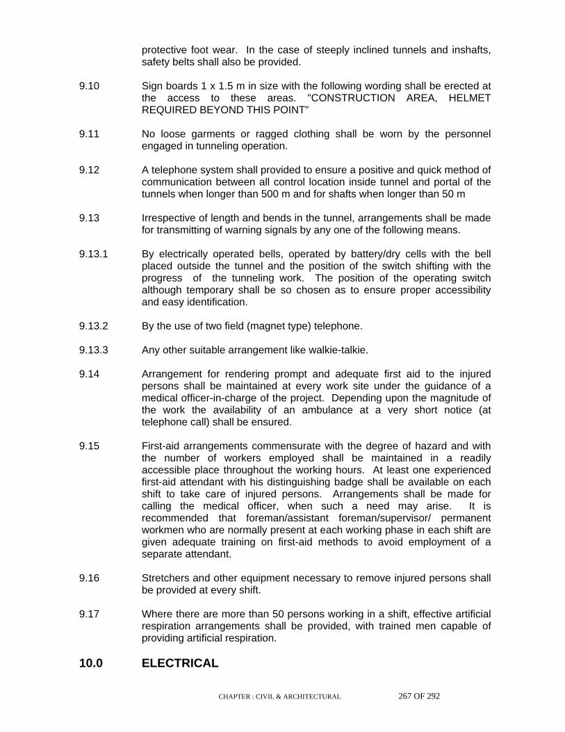
CHAPTER : CIVIL & ARCHITECTURAL 267 OF 292
protective foot wear. In the case of steeply inclined tunnels and inshafts, safety belts shall also be provided.
9.10 Sign boards 1 x 1.5 m in size with the following wording shall be erected at
the access to these areas. "CONSTRUCTION AREA, HELMET REQUIRED BEYOND THIS POINT"
9.11 No loose garments or ragged clothing shall be worn by the personnel
engaged in tunneling operation. 9.12 A telephone system shall provided to ensure a positive and quick method of
communication between all control location inside tunnel and portal of the tunnels when longer than 500 m and for shafts when longer than 50 m
9.13 Irrespective of length and bends in the tunnel, arrangements shall be made
for transmitting of warning signals by any one of the following means. 9.13.1 By electrically operated bells, operated by battery/dry cells with the bell
placed outside the tunnel and the position of the switch shifting with the progress of the tunneling work. The position of the operating switch although temporary shall be so chosen as to ensure proper accessibility and easy identification.
9.13.2 By the use of two field (magnet type) telephone. 9.13.3 Any other suitable arrangement like walkie-talkie. 9.14 Arrangement for rendering prompt and adequate first aid to the injured
persons shall be maintained at every work site under the guidance of a medical officer-in-charge of the project. Depending upon the magnitude of the work the availability of an ambulance at a very short notice (at telephone call) shall be ensured.
9.15 First-aid arrangements commensurate with the degree of hazard and with
the number of workers employed shall be maintained in a readily accessible place throughout the working hours. At least one experienced first-aid attendant with his distinguishing badge shall be available on each shift to take care of injured persons. Arrangements shall be made for calling the medical officer, when such a need may arise. It is recommended that foreman/assistant foreman/supervisor/ permanent workmen who are normally present at each working phase in each shift are given adequate training on first-aid methods to avoid employment of a separate attendant.
9.16 Stretchers and other equipment necessary to remove injured persons shall
be provided at every shift. 9.17 Where there are more than 50 persons working in a shift, effective artificial
respiration arrangements shall be provided, with trained men capable of providing artificial respiration.
10.0 ELECTRICAL
CHAPTER : CIVIL & ARCHITECTURAL 268 OF 292
10.1 Only authorised persons shall handle or otherwise interfere with electrical
equipment. Any person detecting electrical apparatus being handled by an unauthorised person or equipment in unsafe condition must report the matter to the Engineer concerned.
10.2 No person shall work on any live electric conductor or apparatus and no
person shall assist such person on such work, unless he is authorised in that behalf.
10.2.1 After isolating the equipment from the source of supply before the work
begins, a sign 'DONT'T SWITCH ON' must be hung on or near the switch to avoid its being accidentally or inadvertently switched on when persons are working.
10.2.2 Take out the fuses and keep in safe custody. 10.2.3 The switch may be locked if locking arrangement exists. 10.2.4 Earth the equipment, before work, to discharge it and short the terminals as
a precautionary measure against accidental switching ON. 10.2.5 After the work is finished take out Earthing and shorting link. 10.2.6 Remove all tools and materials from the site of work. Replace the fuses
and unlock the switch. 10.2.7 The switch shall only be put 'ON' by the person who switched it 'OFF' or by
the person authorised by him in writing. 10.3 When working on live equipment use one hand only whenever possible, it
is advisable to keep the other hand behind the back. Shocks from hand to hand are most dangerous.
10.4 All persons handling electrical gear in elevated position must use safety
belts. Even a slight shock may cause loss of balance and fall. 10.5 No one shall attempt to extinguish a fire on or near a live electrical
apparatus with water. Water is a good conductor of electricity. Use extinguishers wherever provided. Use sand and blankets etc., if available.
10.6 No person shall use any part of electrical equipment for storing or hanging
clothes, umbrellas or other articles. Serious accidents occur from this practice.
10.7 For attending the work on O.H. lines or equipment use wooden ladders.
Metallic ladders shall not be used. 10.8 Use insulated tools and ensure the insulation is in proper condition
periodically at least once in three months. Use rubber gloves wherever possible.
10.9 As far as possible verbal instructions shall be avoided in case of pre-
arranged shut-down of electrical apparatus.

CHAPTER : CIVIL & ARCHITECTURAL 269 OF 292
10.10 When workers are employed for electrical installations which are already
energised, insulating mats, wearing apparel such as gloves, sleeves and boots as may be necessary shall be provided. The workers shall not wear any rings, watches and carry keys or other materials which are good conductors of electricity.
11.0 MISCELLANEOUS 11.1 The Contractor shall provide necessary fencing and lights to protect the
public from accident. 11.2 Fire extinguishers adequate in number shall be kept by the Contractor at
the site of works where there is risk of fire hazard. 11.3 Adequate washing facilities shall be provided near the place of work. 11.4 When the work is done near any place where there is risk of drowning, all
necessary equipments shall be provided and kept ready for use and all necessary steps taken for prompt rescue of any person in danger and adequate provisions shall be made for prompt first aid treatment of all injuries likely to be sustained during the course of the work.
11.5 These safety provisions shall be brought to the notice of all concerned by
displaying on a Notice Board at a prominent place at the work spot. The persons responsible for compliance of the code shall be named therein by the Contractor.
11.6 To ensure effective enforcement of the rules and regulations relating to
safety precautions, the arrangements made by the Contractor shall be open to inspection by the Engineer and Owner.
11.7 Not withstanding the above clauses there is nothing in those to exempt the
Contractor from the operations of any other Act or Rule in force in the Republic of India.
11.8 All storage, handling and use of flammable liquids shall be under the
supervision of qualified persons. Flammable liquid shall not be stored inside the tunnel
11.9 All sources of ignition shall be prohibited in areas where flammable liquids
are stored, handled and processed. Suitable warning and 'NO SMOKING' signs shall be posted in all such places. Receptacles containing flammable liquids shall be stacked in such a manner as to permit free passage of air between them.
11.10 All combustible materials shall be continuously removed from such areas
where flammable liquids are stored, handled and processed. All spills of flammable liquids shall be cleared up immediately. Containers of flammable liquids shall be tightly capped.
12.0 REPORTING OF ACCIDENT

CHAPTER : CIVIL & ARCHITECTURAL 270 OF 292
All accidents, major or minor must be reported immediately. The
Contractor, will provide first aid to the injured person immediately and the injured person shall report to the first aid station along with the 'INJURED ON WORK' form duly filled in quintuplicate and submit to the Medical Officer of the First Aid Station".
Serious Injury
In case of serious injury, the following procedure shall be adopted by the Contractor :
1. Provide First Aid at his own First Aid Station. 2. Take the injured person to the Hospital along with the "INJURED ON
WORK" form duly filled in. 3. Reporting the accident to the Owner/Engineer by the Contractor.

CHAPTER : CIVIL & ARCHITECTURAL 271 OF 292
Fatal Accident
Fatal accident must be reported immediately to the Engineer/Owner as well as to the Police.
Penalty
Failure to observe the Safety Rules will make the Contractor liable to penalty by way of suspension of work, fine and termination of contract.

CHAPTER : CIVIL & ARCHITECTURAL 272 OF 292
SPECIFICATION FOR CIVIL & ARCHITECTURAL WORKS:
PART VII:LIST OF IS AND IRC CODES REFERRED
ANNEXURE - A
LIST OF IS & IRC CODES REFERRED
IS 383 – 1970 : Specification for coarse & fine aggregates
from natural sources for concrete.
IS 2386 (Part 1 to 8) – 1963 : Method of Test for aggregates for concrete
IS 456 – 2000 : Code of practice for plain and reinforced
concrete.
IS 712 - 1984 : Specification for building limes.
IS 3182 – 1986 : Specification for broken brick (burnt clay )
fine aggregate for use in lime mortar.
IS 269 – 1989 : Specification for 33 grade ordinary Portland
Cement.
IS 455 – 1989 : Code of practice for Portland Slag Cement.
IS 1489 – 1991 : Specification for Portland Pozzolana
Cement.
IS 8041 – 1990 : Specification for rapid hardening Portland
Cement.
IS 8112 – 1989 : Specification for 43 grade ordinary Portland
Cement.
IS 12269 – 1987 : Specification for 53 grade ordinary Portland
Cement.
IS 8043 – 1991. : Specification for Hydrophobic Portland
Cement
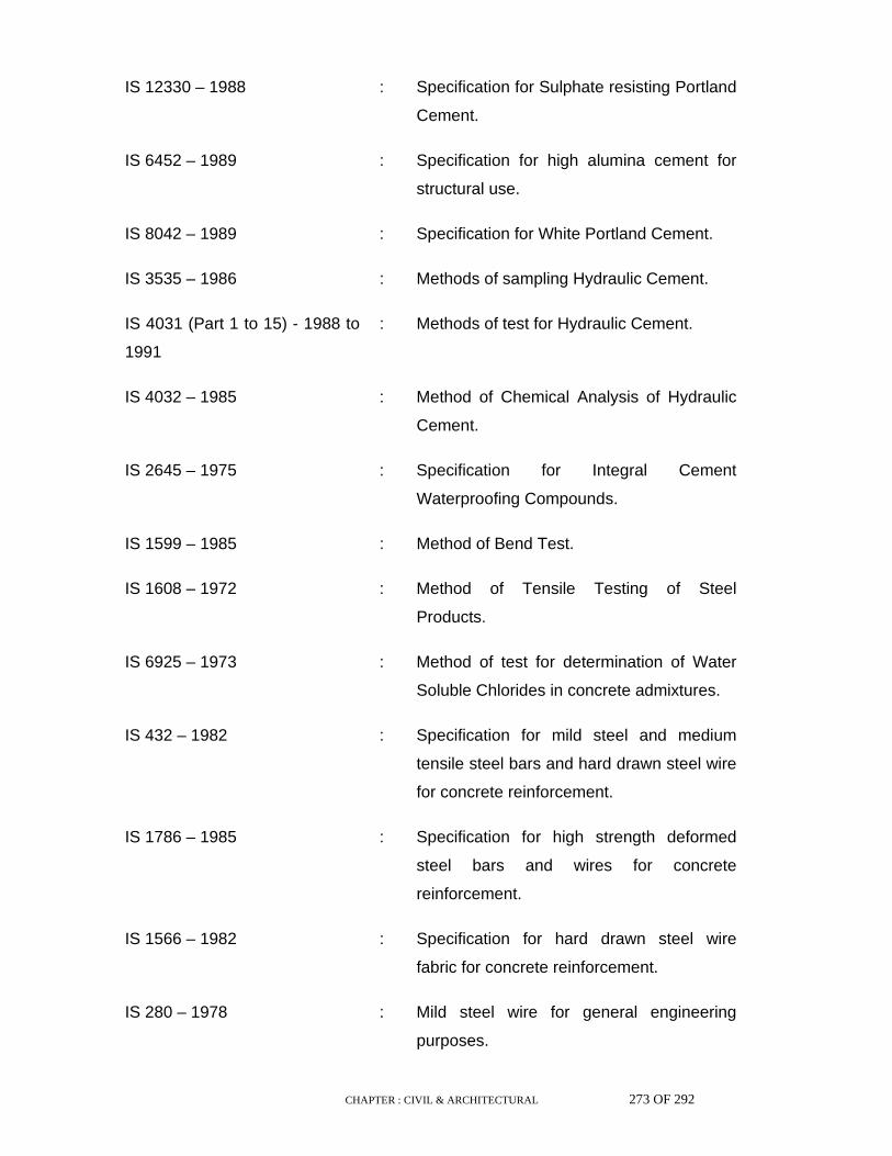
CHAPTER : CIVIL & ARCHITECTURAL 273 OF 292
IS 12330 – 1988 : Specification for Sulphate resisting Portland
Cement.
IS 6452 – 1989 : Specification for high alumina cement for
structural use.
IS 8042 – 1989 : Specification for White Portland Cement.
IS 3535 – 1986 : Methods of sampling Hydraulic Cement.
IS 4031 (Part 1 to 15) - 1988 to
1991
: Methods of test for Hydraulic Cement.
IS 4032 – 1985 : Method of Chemical Analysis of Hydraulic
Cement.
IS 2645 – 1975 : Specification for Integral Cement
Waterproofing Compounds.
IS 1599 – 1985 : Method of Bend Test.
IS 1608 – 1972 : Method of Tensile Testing of Steel
Products.
IS 6925 – 1973 : Method of test for determination of Water
Soluble Chlorides in concrete admixtures.
IS 432 – 1982 : Specification for mild steel and medium
tensile steel bars and hard drawn steel wire
for concrete reinforcement.
IS 1786 – 1985 : Specification for high strength deformed
steel bars and wires for concrete
reinforcement.
IS 1566 – 1982 : Specification for hard drawn steel wire
fabric for concrete reinforcement.
IS 280 – 1978 : Mild steel wire for general engineering
purposes.
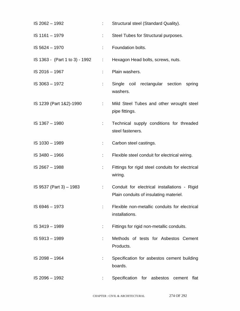
CHAPTER : CIVIL & ARCHITECTURAL 274 OF 292
IS 2062 – 1992 : Structural steel (Standard Quality).
IS 1161 – 1979 : Steel Tubes for Structural purposes.
IS 5624 – 1970 : Foundation bolts.
IS 1363 - (Part 1 to 3) - 1992 : Hexagon Head bolts, screws, nuts.
IS 2016 – 1967 : Plain washers.
IS 3063 – 1972 : Single coil rectangular section spring
washers.
IS 1239 (Part 1&2)-1990 : Mild Steel Tubes and other wrought steel
pipe fittings.
IS 1367 – 1980 : Technical supply conditions for threaded
steel fasteners.
IS 1030 – 1989 : Carbon steel castings.
IS 3480 – 1966 : Flexible steel conduit for electrical wiring.
IS 2667 – 1988 : Fittings for rigid steel conduits for electrical
wiring.
IS 9537 (Part 3) – 1983 : Conduit for electrical installations - Rigid
Plain conduits of insulating materiel.
IS 6946 – 1973 : Flexible non-metallic conduits for electrical
installations.
IS 3419 – 1989 : Fittings for rigid non-metallic conduits.
IS 5913 – 1989 : Methods of tests for Asbestos Cement
Products.
IS 2098 – 1964 : Specification for asbestos cement building
boards.
IS 2096 – 1992 : Specification for asbestos cement flat
CHAPTER : CIVIL & ARCHITECTURAL 275 OF 292
sheets.
IS 9537 (Part 2) – 1981 : Conduit for electrical installations - Rigid
steel conduits.
IS 2614 – 1969 : Method for sampling of fasteners.
IS 1592 – 1989 : Specification for asbestos cement pressure
pipes.
IS 9627 – 1980 : Specification for asbestos cement pressure
pipe (Light duty).
IS 6908 – 1991 : Specification for asbestos cement pipes
and fittings for sewerage and drainage.
IS 1626 (Part 1 to 3) - 1980 to
1991
: Specification for asbestos cement building
pipes & pipe fittings and roofing fittings
IS 459 – 1992 : Specification for unreinforced corrugated
and semi corrugated asbestos cement
sheets
IS 1077 – 1992 : Specification for common burnt clay
building bricks.
IS 3495 (Part 1 to 4) -1992 : Method of Test for burnt clay building
bricks.
IS 3620 – 1979 : Specification for laterite stone block for
masonry.
IS 1121- 1974 : Method of test for determination of strength
properties of natural building stone.
IS 1124 – 1974 : Method of test for determination of water
absorption Sp. Gr. etc. of building stones
IS 1125 – 1974 : Method of test for determination of
weathering of natural building stones.
CHAPTER : CIVIL & ARCHITECTURAL 276 OF 292
IS 1126 – 1974 : Method of test for determination of
durability of building stone.
IS 1127 – 1970 : Recommendation for dimensions and
workmanship of natural building stones for
masonry work.
IS 2185 ( Part-1)-1979 : Specification for concrete masonry unit
Hollow and solid concrete blocks.
IS 2116 – 1980 : Specification for sand for masonry mortar
IS 1542 – 1992 : Specification for sand for plaster.
IS 2185 (Part-2)-1983 : Specification for concrete masonry unit-
Hollow and solid light weight concrete
blocks.
IS 2185 (Part-3)-1984 : Specification for concrete masonry unit -
Auto claved Cellular Aerated concrete
blocks.
IS 6041 – 1985 : Code of practice for construction of Auto
claved Cellular concrete block masonry.
IS 6441 (Part 1 to 9) - 1972 &
1973
: Method of Test for Auto claved Concrete
Products.
IS 3068 – 1986 : Specification for broken brick (burnt clay)
coarse aggregates for use in lime concrete.
IS 2114 – 1984 : Code of practice for laying in-situ terrazo
floor finish.
IS 460 (Part 1 to 3)-1985 : Specification for Test Sieves.
IS 1237 – 1980 : Specification for cement concrete flooring
tiles.
IS 777 – 1988 : Specification for glazed earthen ware wall

CHAPTER : CIVIL & ARCHITECTURAL 277 OF 292
tiles.
IS 1129 – 1972 : Recommendation for dressing of natural
building stone.
IS 1130 – 1969 : Specification for Marble (blocks, slabs and
tiles).
IS 809 – 1992 : Specification for rubber flooring materials
for general purposes.
IS 3462 – 1986 : Specification for unbacked flexible PVC
flooring.
IS 3461 – 1980 : Specification for PVC asbestos floor tiles
IS 2818 – 1990 : Indian Hessians.
IS 653 – 1992 : Linoleum sheets and tiles.
IS 5389 – 1969 : Code of practice for laying hard wood
parquet and wood block flooring.
IS 210 – 1978 : Grey Iron Castings.
IS 2114 – 1984 : Code of practice for laying in-situ terrazzo
finish.
IS 1198 – 1982 : Code of practice for laying of linoleum
flooring.
IS 1003 (Part-2)-1983 : Specification for timber panelled & glazed
shutters, windows and ventilator shutters.
IS 1141 – 1973 : Code of practice for seasoning of timber.
IS 1003 (Part-1) - 1983 & 1991 : Specification for timber panelled & glazed
shutters - Door shutters.
IS 287 – 1973 : Recommendation for maximum permissible
moisture content of timber used for different
CHAPTER : CIVIL & ARCHITECTURAL 278 OF 292
purposes.
IS 2202 (Part-1) - 1983 & 1991 : Specification for wooden flush door shutters
(Solid core type).
IS 2191 (Part-1&2)-1983 : Specification for wooden flush door shutters
(cellular and hollow core type).
IS 3087 – 1985 : Specification for wood particle boards
(Medium density) for general purposes.
IS 3478 – 1966 : Specification for high density wood particle
boards.
IS 3097 – 1980 : Specification for veneered particle boards
IS 303 – 1989 : Specification for plywood for general
purposes.
IS 1328 – 1982 : Specification for veneered decorative
plywood.
IS 205 – 1992 : Specification for non-ferrous metal butt
hinges.
IS 1341 – 1992 : Specification for steel butt hinges.
IS 362 – 1991 : Specification for parliament hinges.
IS 453 – 1973 : Specification for double acting spring
hinges.
IS 3818 – 1992 : Specification for continuous (Piano) hinges.
IS 206 – 1992 : Specification for Tee and Strap hinges.
IS 281 – 1991 : Specification for mild steel sliding door bolts
for use with padlocks.
IS 1019 – 1974 : Specification for rim latches.
IS 2681 – 1979 : Specification for non-ferrous metal sliding

CHAPTER : CIVIL & ARCHITECTURAL 279 OF 292
door bolts for use with padlocks.
IS 204 (Part 1&2)-1991&92 : Specification for tower bolts - Ferrous and
Non-ferrous metals.
IS 208 – 1987 : Specification for door handles.
IS 2209 – 1976 : Specification for mortice locks (vertical
type).
IS 6607 – 1972 : Specification for rebated mortice locks
(vertical type).
IS 1823 – 1980 : Specification for floor door stoppers.
IS 1837 – 1966 : Specification for fan light pivots.
IS 207 – 1964 : Gate and shutter hooks and eyes.
IS 6343 – 1982 : Specification of door closers
(peneumatically regulated) for light door
weighing upto 40 Kg.
IS 8756 – 1978 : Specification for ball catches for use in
wooden Almirah.
IS 6315 – 1992 : Specification for floor springs (hydraulically
regulated) for heavy doors.
IS 7197 – 1974 : Specification for Double action floor spring
(without oil check) for heavy doors
IS 364 – 1993 : Specification for fan light catch.
IS 3828 – 1966 : Specification for ventilator chains.
IS 363 – 1976 : Specification for hasp and staples.
IS 9899 – 1981 : Specification for hat, coat and wardrobe
hooks.
IS 729 – 1979 : Specification for drawer locks, cup-board
CHAPTER : CIVIL & ARCHITECTURAL 280 OF 292
locks and box locks.
IS 3564 – 1986 : Specification for door closers (Hydraulically
regulated).
IS 4351 – 1976 : Specification for steel door frames.
IS 419 – 1967 : Putty for use on window frames.
IS 5187 – 1972 : Specification for flush bolts.
IS 3847 – 1992 : Specification for mortice night latches.
IS 4621 – 1975 : Specification for indicating bolts.
IS 1038 – 1983 : Specification for steel doors, windows and
ventilators.
IS 1977 – 1975 : Structural steel (ordinary quality).
IS 1361 – 1978 : Specification for steel windows for industrial
buildings.
IS 7452 – 1990 : Hot rolled steel sections for doors, windows
and ventilators.
IS 1948 – 1961 : Specification for aluminium doors, windows
and ventilators.
IS 1148 – 1982 : Specification for hot rolled rivet bars for
structural purposes.
IS 1949 – 1961 : Specification for aluminium windows for
industrial buildings.
IS 204 (Part 1) – 1992 : Specification for tower bolts-non-ferrous
metal.
IS 733 – 1983 : Wrought aluminium and aluminium alloy
bars, rods and sections (for general
engineering purposes).

CHAPTER : CIVIL & ARCHITECTURAL 281 OF 292
IS 6248 – 1979 : Specification for metal rolling shutters and
rolling grills.
IS 1081 – 1960 : Code of practice for fixing and glazing of
metal doors, windows and ventilators.
IS 2339 – 1963 : Specification for Aluminium Paint for
general purpose in dual containers.
IS 2835 – 1987 : Flat Transparent sheet glass.
IS 5437 – 1969 : Wired and figured glass.
IS 101 (Part 1 to 8) - 1964 to
1993
: Method of sampling and test for paints,
varnishes and related products.
IS 2074 – 1992 : Ready mixed paint, air drying, red oxide
zink chrome, priming.
IS 5410 – 1992 : Cement paint, colour as required.
IS 427 – 1965 : Distemper, dry, colour as required.
IS 428 – 1969 : Distemper, oil emulsion, colour as required.
IS 348 – 1968 : French polish.
IS 5411 (Part 1&2) - 1972 to
1974
: Plastic emulsion paint.
IS 702 – 1988 : Industrial Bitumen.
IS 73 – 1992 : Paving Bitumen.
IS 217 – 1988 : Cut Back Bitumen.
IS 454 – 1961 : Specification for Digboi type cutback
bitumen.
IS 5467 – 1986 : Specification for shellac Wax.
IS 3384 – 1986 : Specification for Bitumen primer for use in

CHAPTER : CIVIL & ARCHITECTURAL 282 OF 292
water proofing and damp proofing.
IS 290 – 1961 : Specification for Coal Tar Black Paint.
IS 341 – 1973 : Specification for Black Japan, Type A, B &
C.
IS 1322 – 1982 : Specification for bitumen felts for water
proofing and damp proofing.
IS 218 – 1983 : Specification for creosote oil for use as
wood preservative.
IS 3037 – 1986 : Specification for Bitumen mastic for use in
water proofing of roofs.
IS 1580 – 1991 : Specification for Bituminous compound for
water proofing and caulking purposes.
IS 8542 – 1977 : Specification for polish for wooden furniture
paste.
IS 9862 – 1981 : Ready mixed paint, brushing etc.
IS 782 – 1978 : Specification for caulking lead.
IS 405 (Part 1&2) – 1992 : Lead sheet and strips.
IS 5134 – 1977 : Bitumen impregnated paper.
IS 2849 – 1983 : Specification for non load bearing gypsum
partition blocks.
IS 8591 – 1977 : Specification for floor polish paste.
IS 2095 – 1982 : Specification for gypsum plaster boards.
IS 77 – 1976 : Specification for linseed oil, boiled for
paints.
IS 533 – 1973 : Gum Spirit of turpentine (oil of Turpentine).

CHAPTER : CIVIL & ARCHITECTURAL 283 OF 292
IS 1504 – 1974 : Bees Wax.
IS 3536 – 1966 : Ready mixed paint, brushing, wood primer
pink.
IS 8273 – 1984 : Specification for gypsum plaster for use in
the manufacture of fibrous plaster board.
IS 5871 – 1987 : Specification for bitumen mastic for tanking
and damp proofing.
IS 651 – 1992 : Specification for salt glazed stoneware pipe
and fittings.
IS 1729 – 1979 : Sand cast iron spigot and socket soil pipe.
IS 771 (Part 1 to 7) - 1979 to
1985
: Specification for glazed fire clay appliances.
IS 1230 – 1979 : Cast iron rain water pipes and fittings.
IS 774 – 1984 : Flushing cisterns for water closets and
urinals.
IS 2548 (Part 1&2) – 1983 : Specification for plastic seats and cover for
water closet.
IS 1726 – 1991 : Specification for cast iron manhole cover
and frames.
IS 1239 (Part 1&2)-1990 to
1992
: Mild steel Tubes and fittings.
IS 4984 – 1987 : Specification for high density polyethylene
pipes for potable water supplies: Sewerage
and industrial effluents.
IS 2556 (Part 1 to 15) - 1972 to
1985
: Specification for vitreous sanitary
appliances (vitreous china).
IS 7328 – 1992 : High density polyethylene materials.
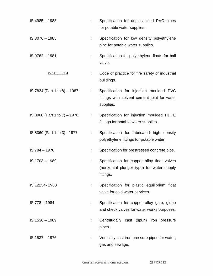
CHAPTER : CIVIL & ARCHITECTURAL 284 OF 292
IS 4985 – 1988 : Specification for unplasticised PVC pipes
for potable water supplies.
IS 3076 – 1985 : Specification for low density polyethylene
pipe for potable water supplies.
IS 9762 – 1981 : Specification for polyethylene floats for ball
valve.
IS 3395 – 1984 : Code of practice for fire safety of industrial
buildings.
IS 7834 (Part 1 to 8) – 1987 : Specification for injection moulded PVC
fittings with solvent cement joint for water
supplies.
IS 8008 (Part 1 to 7) – 1976 : Specification for injection moulded HDPE
fittings for potable water supplies.
IS 8360 (Part 1 to 3) - 1977 : Specification for fabricated high density
polyethylene fittings for potable water.
IS 784 – 1978 : Specification for prestressed concrete pipe.
IS 1703 – 1989 : Specification for copper alloy float valves
(horizontal plunger type) for water supply
fittings.
IS 12234- 1988 : Specification for plastic equilibrium float
valve for cold water services.
IS 778 – 1984 : Specification for copper alloy gate, globe
and check valves for water works purposes.
IS 1536 – 1989 : Centrifugally cast (spun) iron pressure
pipes.
IS 1537 – 1976 : Vertically cast iron pressure pipes for water,
gas and sewage.

CHAPTER : CIVIL & ARCHITECTURAL 285 OF 292
IS 1538 (Part 1 to 23) – 1976 : Sand cast iron spigot and socket soil, waste
and ventilating pipes, fittings and
accessories.
IS 3589 – 1991 : Electrically welded steel pipes for water,
gas and sewage.
IS 781 – 1984 : Specification for cast copper alloy screw
down bib taps and stop valves for water
services.
IS 1239 (Part 1&2) - 1990 to 1992 : Mild steel tubes and fittings.
IS 779 – 1978 : Specification for water meters.
IS 1795 – 1982 : Specification for pillar taps for water supply
purposes.
IS 1363 (Part 1 to 3) - 1992 : Dimensions for screw thread run-outs and
undercuts.
IS 2016 – 1967 : Plain washers.
IS 638 – 1979 : Sheet rubber jointing and rubber insertion
jointing.
IS 4127 – 1983 : Code of practice for laying of glazed
stoneware pipes.
IS 458 – 1988 : Specification for precast concrete pipes.
IRC 19 – 1981 : Standard specification and code of practice
for water Bound macadam.
IRC 29 – 1988 : Tentative specification for 4 cm Asphaltic
concrete surface course.
IRC 15 – 1981 : Standard specification and code of practice
for construction of concrete roads.
IS 6313 – 1981 : Code of practice for antitermite measures in
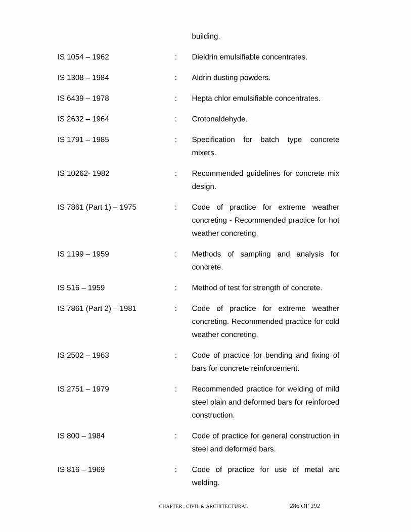
CHAPTER : CIVIL & ARCHITECTURAL 286 OF 292
building.
IS 1054 – 1962 : Dieldrin emulsifiable concentrates.
IS 1308 – 1984 : Aldrin dusting powders.
IS 6439 – 1978 : Hepta chlor emulsifiable concentrates.
IS 2632 – 1964 : Crotonaldehyde.
IS 1791 – 1985 : Specification for batch type concrete
mixers.
IS 10262- 1982 : Recommended guidelines for concrete mix
design.
IS 7861 (Part 1) – 1975 : Code of practice for extreme weather
concreting - Recommended practice for hot
weather concreting.
IS 1199 – 1959 : Methods of sampling and analysis for
concrete.
IS 516 – 1959 : Method of test for strength of concrete.
IS 7861 (Part 2) – 1981 : Code of practice for extreme weather
concreting. Recommended practice for cold
weather concreting.
IS 2502 – 1963 : Code of practice for bending and fixing of
bars for concrete reinforcement.
IS 2751 – 1979 : Recommended practice for welding of mild
steel plain and deformed bars for reinforced
construction.
IS 800 – 1984 : Code of practice for general construction in
steel and deformed bars.
IS 816 – 1969 : Code of practice for use of metal arc
welding.
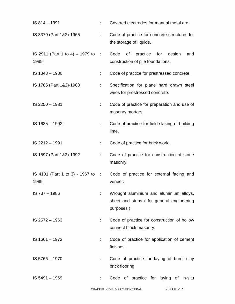
CHAPTER : CIVIL & ARCHITECTURAL 287 OF 292
IS 814 – 1991 : Covered electrodes for manual metal arc.
IS 3370 (Part 1&2)-1965 : Code of practice for concrete structures for
the storage of liquids.
IS 2911 (Part 1 to 4) – 1979 to
1985
: Code of practice for design and
construction of pile foundations.
IS 1343 – 1980 : Code of practice for prestressed concrete.
IS 1785 (Part 1&2)-1983 : Specification for plane hard drawn steel
wires for prestressed concrete.
IS 2250 – 1981 : Code of practice for preparation and use of
masonry mortars.
IS 1635 – 1992: : Code of practice for field slaking of building
lime.
IS 2212 – 1991 : Code of practice for brick work.
IS 1597 (Part 1&2)-1992 : Code of practice for construction of stone
masonry.
IS 4101 (Part 1 to 3) - 1967 to
1985
: Code of practice for external facing and
veneer.
IS 737 – 1986 : Wrought aluminium and aluminium alloys,
sheet and strips ( for general engineering
purposes ).
IS 2572 – 1963 : Code of practice for construction of hollow
connect block masonry.
IS 1661 – 1972 : Code of practice for application of cement
finishes.
IS 5766 – 1970 : Code of practice for laying of burnt clay
brick flooring.
IS 5491 – 1969 : Code of practice for laying of in-situ

CHAPTER : CIVIL & ARCHITECTURAL 288 OF 292
granolithic concrete flooring topping.
IS 3316 – 1974 : Specification for structural granite.
IS 1196 – 1978 : Code of practice for laying bitumen mastic
flooring.
IS 1195 – 1978 : Specification for bitumen mastic for flooring.
IS 3462 – 1986 : Specification for unbacked flexible PVC
flooring.
IS 1198 – 1982 : Code of practice for laying fixing and
maintenance of linoleum floor.
IS 848 – 1974 : Specification for synthetic resin adhesive
for plywood.
IS 4457 – 1982 : Specification for ceramic unglazed vitreous
acid resisting tiles.
IS 851 – 1978 : Specification for synthetic resin adhesive
for construction work (non structural) for
wood.
IS 2202 (Part 1&2) - 1981 to
1991
: Specification for wooden flush door
shutters.
IS 102 – 1962 : Ready mixed paint.
IS 1081 – 1960 : Code of practice for fixing and glazing of
metal doors.
IS 6248 – 1979 : Specification for metal rolling shutters and
rolling grills.
IS 1868 – 1982 : Anodic coatings on aluminium and its
alloys.
IS 2065 – 1983 : Code of practice for water supply in
buildings.
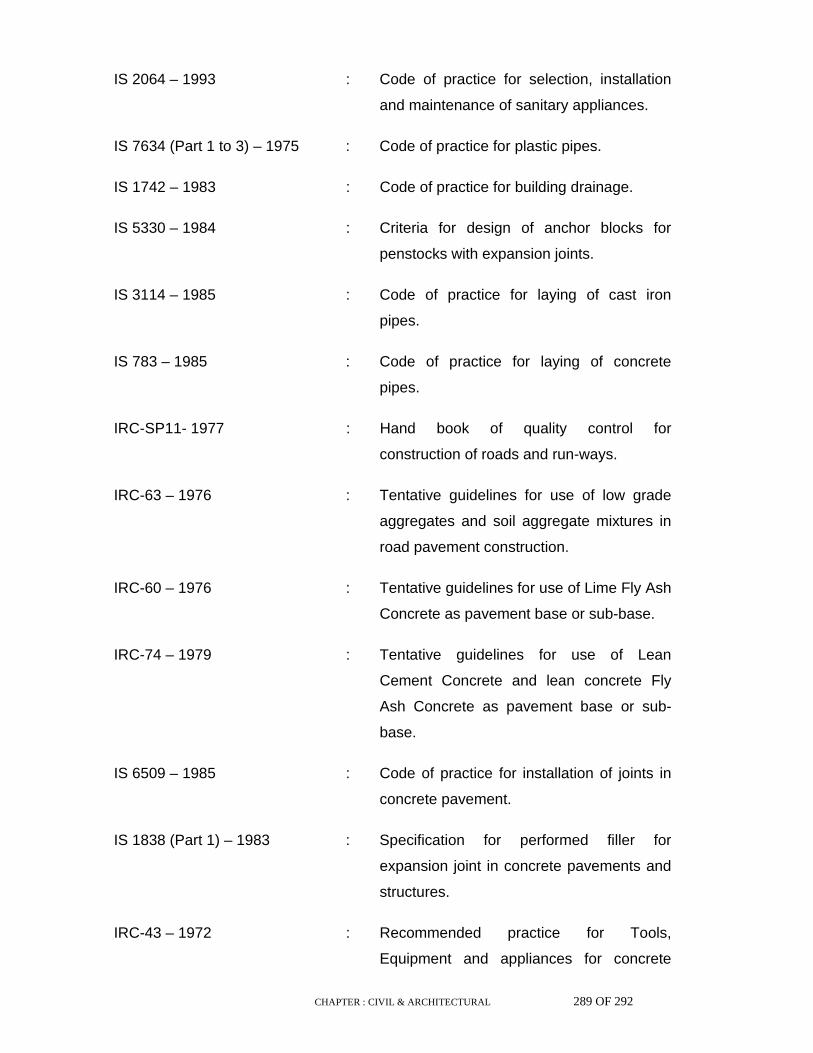
CHAPTER : CIVIL & ARCHITECTURAL 289 OF 292
IS 2064 – 1993 : Code of practice for selection, installation
and maintenance of sanitary appliances.
IS 7634 (Part 1 to 3) – 1975 : Code of practice for plastic pipes.
IS 1742 – 1983 : Code of practice for building drainage.
IS 5330 – 1984 : Criteria for design of anchor blocks for
penstocks with expansion joints.
IS 3114 – 1985 : Code of practice for laying of cast iron
pipes.
IS 783 – 1985 : Code of practice for laying of concrete
pipes.
IRC-SP11- 1977 : Hand book of quality control for
construction of roads and run-ways.
IRC-63 – 1976 : Tentative guidelines for use of low grade
aggregates and soil aggregate mixtures in
road pavement construction.
IRC-60 – 1976 : Tentative guidelines for use of Lime Fly Ash
Concrete as pavement base or sub-base.
IRC-74 – 1979 : Tentative guidelines for use of Lean
Cement Concrete and lean concrete Fly
Ash Concrete as pavement base or sub-
base.
IS 6509 – 1985 : Code of practice for installation of joints in
concrete pavement.
IS 1838 (Part 1) – 1983 : Specification for performed filler for
expansion joint in concrete pavements and
structures.
IRC-43 – 1972 : Recommended practice for Tools,
Equipment and appliances for concrete
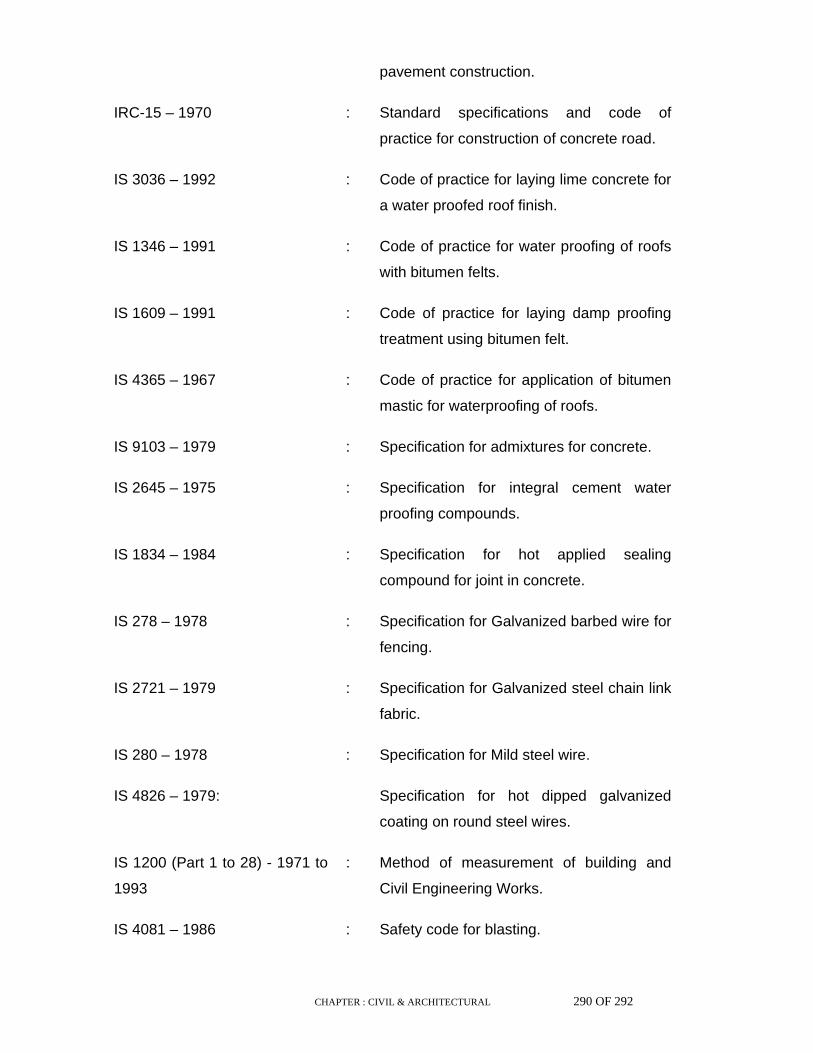
CHAPTER : CIVIL & ARCHITECTURAL 290 OF 292
pavement construction.
IRC-15 – 1970 : Standard specifications and code of
practice for construction of concrete road.
IS 3036 – 1992 : Code of practice for laying lime concrete for
a water proofed roof finish.
IS 1346 – 1991 : Code of practice for water proofing of roofs
with bitumen felts.
IS 1609 – 1991 : Code of practice for laying damp proofing
treatment using bitumen felt.
IS 4365 – 1967 : Code of practice for application of bitumen
mastic for waterproofing of roofs.
IS 9103 – 1979 : Specification for admixtures for concrete.
IS 2645 – 1975 : Specification for integral cement water
proofing compounds.
IS 1834 – 1984 : Specification for hot applied sealing
compound for joint in concrete.
IS 278 – 1978 : Specification for Galvanized barbed wire for
fencing.
IS 2721 – 1979 : Specification for Galvanized steel chain link
fabric.
IS 280 – 1978 : Specification for Mild steel wire.
IS 4826 – 1979: Specification for hot dipped galvanized
coating on round steel wires.
IS 1200 (Part 1 to 28) - 1971 to
1993
: Method of measurement of building and
Civil Engineering Works.
IS 4081 – 1986 : Safety code for blasting.
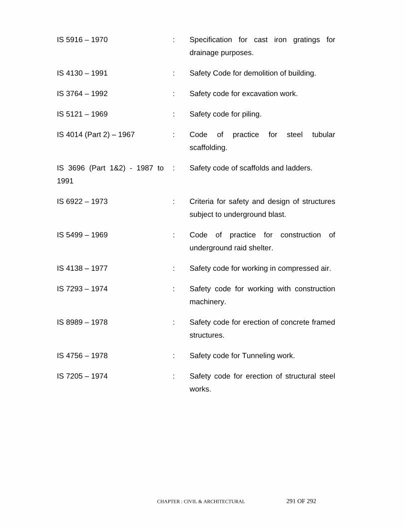
CHAPTER : CIVIL & ARCHITECTURAL 291 OF 292
IS 5916 – 1970 : Specification for cast iron gratings for
drainage purposes.
IS 4130 – 1991 : Safety Code for demolition of building.
IS 3764 – 1992 : Safety code for excavation work.
IS 5121 – 1969 : Safety code for piling.
IS 4014 (Part 2) – 1967 : Code of practice for steel tubular
scaffolding.
IS 3696 (Part 1&2) - 1987 to
1991
: Safety code of scaffolds and ladders.
IS 6922 – 1973 : Criteria for safety and design of structures
subject to underground blast.
IS 5499 – 1969 : Code of practice for construction of
underground raid shelter.
IS 4138 – 1977 : Safety code for working in compressed air.
IS 7293 – 1974 : Safety code for working with construction
machinery.
IS 8989 – 1978 : Safety code for erection of concrete framed
structures.
IS 4756 – 1978 : Safety code for Tunneling work.
IS 7205 – 1974 : Safety code for erection of structural steel
works.

HINDUSTAN PETROLEUM CORPORATION LIMITED
BAHADURGARH TIKRIKALAN PIPE LINE PROJECT
Page 1 of 46
CONTENTS
Sl. No.
Section Description Page Nos.
1 - Scope and general description of work 2 – 3 2 1 Fabrication of Steel Structures 4 – 14 3 2 Erection of Steel Structures 15 – 19 4 3 Fabrication and Erection of Miscellaneous structures 20– 23 5 4 Painting of Steel Structures 24 – 27 6 5 Special conditions of contract 28- 35
LIST OF ANNEXURES
Sl. No.
Annexure Description
1 A Permissible Deviation in pitch and gauge of holes for bolts of normal accuracy.
2 B Tolerance of assembled components of steel structures. 3 C Permissible Deviation in assembly of welded joints. 4 D Tolerance in erected steel structures. 5 E Material of Construction.

HINDUSTAN PETROLEUM CORPORATION LIMITED
BAHADURGARH TIKRIKALAN PIPE LINE PROJECT
Page 2 of 46
01.00 Scope and general description of work 01.01 Scope of work This Specification shall apply to supply, fabrication and erection of steel
structures in Pump Houses, Dosing Shed, Car parking shed and miscellaneous steel structures and general structural work. For technological structures, additional stipulations shall be considered.
There shall be following structural shed and miscellaneous units designated
as follows:
Main Pump House Booster Pump house Dosing Shed Car Parking Cross over and platform at Pump house manifold area Chain link Fencing and Gate
01.02 General description of structures The steel structures shall consist of but not limited to columns, column
bracing, roof Rafters, Crane Girders, Crane Rails, Auxiliary Girder, roof girders, Roof Purlins, side runners, roof bracing, sag angles, sag rods, platforms, walkways, stairs, ladders, handrails, gutters, down-comers, roof cladding, side cladding, Pipe Supports, crossover etc.
This Specification covers the structural steelwork for Pump houses and
general structural steel works. The structural work shall not be limited to the following description but shall be guided by technical/ technological aspects for the total scope of work.
Brief description of major works under the item is as follows:
01.02.1 Main Pump house shed shall be approximately 20m (L) x 7m (w) c/c in plan
and shall have a clear height of 6.0m above FFL. The shed shall have an EOT Crane of 5.0T capacity at 5.1m level for maintenance of pumps. Roof & side cladding shall be of Zincalume high tensile colour coated steel sheets.
01.02.2 Booster Pump house shed shall be approximately 20m (L) x 7m (w) c/c in
plan and shall have a clear height of 6.0m above FFL. The shed shall have an HOT Crane of 5.0T capacity at 5.1m level for maintenance of pumps. Roof & side cladding shall be of Zincalume high tensile colour coated steel sheets

HINDUSTAN PETROLEUM CORPORATION LIMITED
BAHADURGARH TIKRIKALAN PIPE LINE PROJECT
Page 3 of 46
01.02.3 Dosing shed shall be approximately 5m (L) x 3m (w) c/c in plan and shall
have a clear height of 2.5m above FFL. Roof & side cladding shall be of Zincalume high tensile colour coated steel sheets
01.02.4 Car Parking shed shall be approximately 12m (L) x 6m (w) in plan and shall
have a clear height of 3.0 above FFL.Roof & gable end cladding shall be of Zincalume high tensile colour coated steel sheets
01.02.5 Valve operating Platform and crossover /Stair case at Pump house
Manifold area 01.02.6 Pipes and Valves support structures
The description and sizes mentioned above are indicative only. The works shall be executed as per actual sizes specified in the design drawings

HINDUSTAN PETROLEUM CORPORATION LIMITED
BAHADURGARH TIKRIKALAN PIPE LINE PROJECT
Page 4 of 46
SECTION 1- FABRICATION OF STEEL STRUCTURES
02.00 Scope of Work 02.01 The scope of work under fabrication includes, but is not limited to, the
following: a. Preparation and supply of material indents, bolt lists, bought out items list
etc. b. Procurement and collection of all steel materials from stockyards/stores
including loading, transportation, unloading and stacking and storing on skids or supports.
c. Procurement and collection of all consumables like fasteners, bolts, nuts,
washers, electrodes, paints, glass, shims, packs, putty, gases, etc. including allowance for spares and wastage.
d. Preparation and submission of fabrication drawings,
modification/rectification sketches, As-Built drawings, erection drawings, Bill of Materials, and shipping documents for approval of the Owner.
e. Preparation of design calculations for non-standard connections, temporary
bracing etc. for approval of the Owner. f. Cold straightening of section and plates, whenever they are bent and
kinked. g. Fabrication of all steel structural components covered under tender
drawings, design drawings and generally described under the scope of the project.
h. Making arrangements for conducting tests, such as chemical analysis,
physical and mechanical tests on raw materials where specified/as directed by the Owner.
i. Making arrangements for providing all facilities for conducting ultrasonic,
x-ray or -ray tests of welds, getting the tests conducted by reputed testing laboratories making available test films/graphs, reports and interpretation.
j. Control Assembly of steel structural components at shop, wherever
required. k. Preparation of steel structural surfaces for painting as provided in the
Specification/drawings. l. Application for one primer coat of painting at shop, as specified in the
design drawings/Specification.
HINDUSTAN PETROLEUM CORPORATION LIMITED
BAHADURGARH TIKRIKALAN PIPE LINE PROJECT
Page 5 of 46
m Loading, transportation from fabrication workshop to site of erection and
unloading of all steel structural components/units/assemblies at site. n. Preparation of ‘As-Built’ drawings. 03.00 Preparation of fabrication and erection Drawings 03.01 Fabrication drawings shall be prepared based on design drawings
approved by owner for steel structures. 03.02 Drawings shall be prepared in metric system as per IS 696:1972 and IS
813:1986. The fabrication drawings shall specify the following details: a. Type, size and length of welds in case of welded connections (specifying
clearly whether welds are shop welds or site welds). Length of weld specified shall be the effective length (excluding end craters).
b. In case of bolted joints, arrangement of bolts and specification of bolts,
nuts, etc. (specifying clearly whether bolts are shop bolts or site bolts). c. Specification of electrode/wire flux. d. If required, special provisions to be mentioned in the drawings for handling
of structures during and after fabrication. e. Paint Specification and corresponding surface preparation. f. General Arrangement/Marking Plan. g. Reference to corresponding design drawings. h. Bill of Material indicating mark number-wise material requirement giving
details of size, weight, material specification, identification, numbers of each item mark, number of items required etc.
i. Layout showing all connecting members complete with joint details,
wherever required, in order to specify clearly various fabrication and erection requirements as per design drawings.
j. Appropriate edge preparation in case of butt/groove welds in accordance
with IS 9595: 1980 for all plates and sections having thickness greater than 8mm.
k. Erection clearances in order to facilitate smooth erection at site (ref. Clause
no.11.2.2.of IS 800: 2007). l. Each erection piece shall be clearly identified by an erection mark in these
drawings. All loose members shall be given part mark, which shall be 'wired on' the main erection piece for despatch.

HINDUSTAN PETROLEUM CORPORATION LIMITED
BAHADURGARH TIKRIKALAN PIPE LINE PROJECT
Page 6 of 46
03.03 Fabrication drawings shall be prepared in such a manner that fabricated
structures can be dispatched from the fabrication yard to the erection site with maximum economic transportable size so as to reduce work involved at site to a minimum.
03.04 Bracing members shall be connected for 80% of the capacity of the
member or the force specified in the design drawing, whichever is more. For single angle bracing members, full area shall be considered effective for this purpose.
03.05 Standard simple beam connections, unless otherwise stated in the
drawings, shall be designed and detailed for 60% of beam shear/moment carrying capacity.
03.06 Wherever there is a risk of nuts becoming loose due to vibration, lock nuts
shall be provided or nuts shall be welded after alignment and tightening. 03.07 For all connections by permanent bolting, two washers shall be used, one
washer bearing against the head and the other bearing against the nut. 03.08 Detailing of structural steel members subject to dynamic loading shall be
such as to ensure smooth transition of load, as well as best behavior under stress due to fatigue. Welding across tension flange of beams is not permitted.
03.09 For connection details, the allowable stress for materials, welds, bolts etc.,
shall be as per IS 800: 2007 and IS 816: 1969 or as specified in the drawing.
03.10 The Contractor shall be responsible for designing and detailing all
connections. The design of connections shall provide adequate strength for transfer of force in the structural elements as indicated on design drawings. Detailing shall be such that erection shall be convenient and free from all interfaces, drilling and cutting at site.
04.00 Materials 04.01 Structural Steel 04.01.01 Structural steel and other related materials for construction shall conform to
Annexure-E. 04.01.02 Due to non-availability of specified materials, suitable substitutions may be
provided with the consent of the Owner. Such substitution shall be incorporated in the As-Built’ drawings.
04.01.03 All the items are to be cut as per requirements of the drawing. If joints are to
be provided in any item in order to meet requirements of size and shape, cutting plan showing locations of joints shall be prepared for consideration

HINDUSTAN PETROLEUM CORPORATION LIMITED
BAHADURGARH TIKRIKALAN PIPE LINE PROJECT
Page 7 of 46
of the Owner. Joints so provided shall be incorporated in ‘As-Built’ drawings.
04.01.04 Rolling and cutting tolerances shall be as per IS 1852: 1985. 04.01.05 Only tested materials shall be used unless the Owner permits use of
untested materials for certain secondary structural members. If test certificate for the material is not available from the main producer, the following tests shall be carried out at the discretion of the Owner:
a. Chemical Composition b. Mechanical Properties c. Weldability test 04.02 Bolts and Nuts 04.02.01 Black hexagonal bolts, nuts and lock nuts shall conform to IS 1363: 1992. 04.02.02 Precision and semi-precision hexagonal bolts, screws, nuts and lock nuts
shall conform to IS 1364: 1992. 04.02.03 High Tensile Friction Grip (HSFG) bolts, High Strength structural nuts and
hardened steel washers shall conform to IS 3757: 1985, IS 6623: 1985 and IS 6649: 1985 respectively
04.03 Electrodes 04.03.01 Mild steel electrodes shall conform to IS 814: 1991. Electrodes to be used
for submerged arc welding shall conform to IS 7280: 1974. 05.00 Storage of materials 05.01 Materials shall be stored and stacked properly ensuring that place is
properly drained and is free from dirt. It shall be ensured that no damage is caused due to improper stacking.
06.00 Material Preparation 06.01 Cut edges shall be finished smooth by grinding or machining wherever
necessary. Sufficient allowance (3mm to 5mm) should be kept in the items in case machining is necessary.
06.02 Cutting may be done by gas cutting, shearing, cropping or sawing. 06.03 Sufficient shrinkage allowance (@ 1mm/m) shall be kept wherever heavy
welding is involved. 06.04 Straightening and bending shall be done in cold condition as far as
practicable.
HINDUSTAN PETROLEUM CORPORATION LIMITED
BAHADURGARH TIKRIKALAN PIPE LINE PROJECT
Page 8 of 46
06.05 If required, straightening and bending may be done by application of heat
between 900°C and 1100°C. Cooling down of the heated item shall be done slowly.
07.00 Drilling and punching of holes 07.01 Drilling and punching of holes for bolts shall be done as per Clause
no.11.2.4 of IS 800: 2007, unless otherwise specified by the Owner. 07.02 Drifting of holes for bolts during assembly shall not cause enlargement of
holes beyond permissible limit or damage the metal. 07.03 Holes for bolted connection should match well to permit easy entry of bolts.
Gross mismatch of holes shall be avoided. 07.04 Permissible deviation in holes for mild steel bolts of normal accuracy is
given in the Annexure-A. 08.00 Assembly for fabrication 08.01 Fabrication of all structural steelwork shall be in accordance with IS 800
and in conformity with various clauses of this Specification unless otherwise specified in the drawings.
08.02 Fabrication of structures shall preferably be taken up as per the sequence
of erection. 08.03 All erection units shall bear erection mark number and reference drawing
number at a prominent location on the structures for easy identification at site.
08.04 Fabricated structures shall conform to tolerance as specified in this
Specification and in IS 7215: 1974. In case of contradiction, tolerance specified in this Specification shall prevail.
08.05 All the components of structures shall be free from twist, bend, damage,
etc. 08.06 Suitable jigs and fixtures shall be used to avoid any distortion during
welding shall carry out assembly of structures. 08.07 Cutting of items especially for trusses and bracing members shall be done
only after verifying lengths and sections as per layout. 08.08 Surface, wherever machining is specified, shall be either planed or milled or
ground to ensure maximum contact.

HINDUSTAN PETROLEUM CORPORATION LIMITED
BAHADURGARH TIKRIKALAN PIPE LINE PROJECT
Page 9 of 46
08.09 If milling or machining is planned after the assembly is over, sufficient
allowance (5mm to 15mm) shall be kept in the items where milling/machining is to be done.
08.10 If pre-bending of the plate is required to avoid welding distortion, it shall be
done in cold condition. 08.11 If extra joints are required to be provided in any column, prior approval
should be obtained from the Owner. However, as a general guidance, the splice joints of column shall be of full strength butt weld and, wherever possible, shall be located at zones of minimum or substantially lesser stresses.
08.12 Splice joints of flange and web should preferably be staggered. 08.13 Sufficient trial assembly of fabricated components (dispatch elements) shall
be carried out in the fabrication works to control the accuracy of workmanship.
08.14 Where necessary, washers shall be tapered or otherwise suitably shaped to
give the heads of nuts and bolts satisfactory bearing. 08.15 The threaded portion of each bolt shall project through the nut at least by
one thread. 08.16 Tolerance of assembled components of structures shall be as per
Annexure-B. 08.17 Permissible deviation from designed (true) geometrical form of the
despatch elements shall be in accordance with IS 7215: 1974. 09.00 Welding 09.01 Contractor shall work out welding procedure for Owner's approval
considering the following: a. Specification and thickness of steel, b. Specification of electrode or/and base wire, c. Welding process (manual arc welding, submerged arc welding, etc.) d. Type of structures to be welded (thickness of components meeting at a
joint), e. Pre and post heating requirements, f. Preparation of fusion faces, g. Sequence of welding, h. Weather conditions, i. Use of jigs and fixtures, etc., j. Type of non-destructive testing to be carried out, k. Inspection procedure to be followed and l. Design requirements of the joints.

HINDUSTAN PETROLEUM CORPORATION LIMITED
BAHADURGARH TIKRIKALAN PIPE LINE PROJECT
Page 10 of 46
09.02 Welding of any load bearing structure shall be carried out only by the
person who has passed welder's qualification as per IS 7318 (Part 1): 1974. 09.03 All metal arc welding shall be carried out as per IS 9595: 1980. 09.04 Submerged arc welding shall be carried out as per IS 4353: 1967. 09.05 Electrodes shall conform to relevant clauses of this Specification. 09.06 Electrodes shall be stored in a dry place. Electrodes, whose coatings are
damaged due to absorption of moisture or due any other reasons, shall not be used.
09.07 For suitability of wire flux combination, procedure test shall be carried out
as per IS 3613: 1974, if required. 09.08 Welding shall, unless otherwise specified, be done using electric arc
process. Generally submerged arc welding, automatic or semi-automatic shall be employed. Only where it is not practicable, manual arc welding may be resorted to. In case of manual arc welding, recommendations of electrode manufacturer are to be strictly followed.
09.09 Surfaces to be welded shall be smooth, uniform and free from fins, tears,
notches or any other defect that may adversely affect welding. 09.10 For welds with multiple run weld deposits, the subsequent run shall be done
only after thorough removal of slag and proper cleaning of surface. 09.11 Fillet weld shall have the correct profile with smooth transition into parent
metal. Dressing of welds, if specified, shall be done by such method that does not cause grooving or any other surface defects on the weld or on the parent metal.
09.12 All butt welds shall start and end with run-on and run-off plates. All such
plates shall be carefully trimmed off by gas cutting after welding is over. 09.13 Fillet welds shall not be stopped at corners but shall be returned round
them 09.14 If butt weld is to be ground flush with the surface of the member as per
drawing, adequate reinforcement shall be built up and then the same shall be chipped off and ground flush. The grinding is to done in the direction of stress flow till the transverse marks are eliminated.
09.15 Welding shall not be done under such weather conditions that might
adversely affect the efficiency of the welding. 09.16 Manipulators shall be used wherever necessary and shall be designed to
facilitate welding and ensure that all welds are easily accessible to the operators.
HINDUSTAN PETROLEUM CORPORATION LIMITED
BAHADURGARH TIKRIKALAN PIPE LINE PROJECT
Page 11 of 46
09.17 Ends of structural members and portions of gussets to be welded at site
shall be left unpainted. 09.18 Permissible deviation in assembly of weld joints shall be in accordance with
Annexure-C. 10.00 Inspection and Testing 10.01 The Owner/Inspector shall have free access at all times to those parts of
the premises of the Contractor or his Subcontractor that are concerned with the fabrication work. The Owner/Inspector shall be afforded all reasonable facilities at all stages of preparation, fabrication and trial assemblies for satisfying himself that the fabrication is being undertaken strictly as per the approved fabrication drawings and in accordance with the provisions of relevant Specifications.
10.02 The Contractor shall supply free of charge all gauges and templates, tools,
apparatus, labour and assistance for checking the fabricated structures. The Owner/Inspector may, at his discretion, check the test results obtained at the Contractor's works, by independent test at the Government Test House or elsewhere, and should the material so tested be found to be unsatisfactory, the cost of such test shall be borne by the Contractor.
10.03 The Contractor shall make all necessary arrangements for stage inspection
by Owner/Inspector during the fabrication at shop and incorporate all on the spot instructions/changes conveyed in writing to the Contractor.
10.04 Material improperly detailed or wrongly fabricated shall be reported to the
Owner/Inspector and shall be made good as directed. Minor misfits which can be remedied by moderate use of drift pins, moderate amount of reaming and/or slight chipping may be corrected in that manner if, in the opinion of the Owner/Inspector, the strength or appearance of the structure will not be adversely affected. In the event the Owner/Inspector directs otherwise, the items will be rejected and a completely new piece shall be fabricated. The cost of correcting errors shall be to the account of the Contractor.
10.05 a. The Owner /Inspector shall have the power to certify before any structure
Is submitted for inspection that the same is not in accordance with the Contract owing to the adoption of any unsatisfactory method of fabrication, to reject any structure as not being in accordance with Specification and approved fabrication drawings and to insist that no structure or part of the structure once rejected is resubmitted for inspection/test, except in cases where the Owner/Inspector or any

HINDUSTAN PETROLEUM CORPORATION LIMITED
BAHADURGARH TIKRIKALAN PIPE LINE PROJECT
Page 12 of 46
representative authorised by the Owner/Inspector considers the defects as rectifiable.
b. If, on rejection of a structure by the Owner/Inspector, the Contractor fails to
make satisfactory progress within the stipulated period, the Owner shall be at liberty to cancel the Contract and get the structure fabricated or authorise the fabrication of the structures at any other place he chooses at the risk and cost of the Contractor, without prejudice to any action being taken in addition to terms of General Conditions of Contract.
c. The decision of the Owner/Inspector regarding rejection shall be final and
binding on the Contractor. d. The Specification prescribes various tests at specified intervals for
ascertaining the quality of the work done. If the tests prove unsatisfactory, Owner/Inspector shall have liberty to order the Contractor to redo the work done in that period and/or to order such alterations and strengthening as may be necessary at the cost of the Contractor. The Contractor shall be bound to carry out such orders failing which the rectification/redoing will be done by the Owner through other agencies and the cost recovered from the Contractor.
e. Notwithstanding any inspection at the fabrication yard, the Owner/Inspector
shall have the liberty to reject, without being liable for compensation any fabricated members or materials brought to site that do not conform to Specification/approved fabrication drawings/design drawings.
f. All rejected materials shall be removed from the fabrication yard by the
Contractor at his own cost and within the time stipulated by the Owner/Inspector.
11.00 Control in Welding 11.01 The extent of quality control in respect of welds for structural elements
structures shall be as follows and shall be conducted by the Contractor at his own cost:
a. Visual Examination: All welds shall be 100% visually inspected to check the
presence of undercuts, visually identifiable surface cracks in both welds and base metals, unfilled craters, improper weld profile and size, excessive reinforcement in weld, surface porosity etc.
Before inspection, the surface of weld metal shall be cleaned of all slag,
spatter matter, scales etc. by using wire brush or chisel. b. Dye Penetration Test (DPT): This shall be carried out for all important fillet
and groove welds to check surface cracks, surface porosity etc. Dye Penetration Test shall be carried out in accordance with American
National Standard ASTM E165.
HINDUSTAN PETROLEUM CORPORATION LIMITED
BAHADURGARH TIKRIKALAN PIPE LINE PROJECT
Page 13 of 46
c. Ultrasonic testing: This test shall be conducted for heat affected zones in
important load bearing butt welds as desired by the Owner/Inspector to detect cracks, lack of fusion, slag inclusions, gas porosity etc.
Ultrasonic testing shall be carried out in accordance with American National
Standard ANSI/AWS D1.1-96 Chapter -6: Part F. Before ultrasonic test is carried out, any surface irregularities like undercuts,
sharp ridges etc. shall be rectified. Material surface to be used for scanning by probes must allow free movement of probes. For this purpose, surface shall be prepared to make it suitable for carrying out ultrasonic examination.
d. Radiographic Testing (x-ray and γ-ray Examination): This test shall be
limited to 2% of length of welds for welds made by manual or semi- automatic welding and 1% of length of weld if made by automatic welding machines. The location and extent of welds to be tested by this method shall be decided by the Owner/Inspector to detect gas porosity, slag inclusions, lack of penetration, lack of fusion, cracks etc.
Radiographic testing shall be conducted in accordance with American
National Standard ANSI/AWS D1.1-96 Part E. Any surface irregularity like undercuts, craters, pits etc. shall be removed
before conducting radiographic test. The length of weld to be tested shall not be more than 0.75xfocal distance. The width of the radiographic film shall be width of the welded joint plus 20mm on either side of the weld.
12.00 Acceptable limits in Weld Defects 12.01 Limits of Acceptability of weld defects shall be as follows: a. Visual inspection and Dye Penetration Test: The limits of acceptability for
defects detected during visual inspection and Dye Penetration Test shall be in accordance with Clause 8.15.1.
b. Ultrasonic Testing: The limits of acceptability for defects detected during
ultrasonic testing shall be in accordance with Clause 8.15.4 of American National Standard ANSI/AWS D1.1-96 Chapter 6: Part C.
c. Radiographic testing: The limits of acceptability for defects detected during
radiographic testing shall be in accordance with Clause 8.15.3 of American National Standard ANSI/AWS D1.1-96 Chapter 6: Part C.
13.00 Rectification of defects in Welds 13.01 In case of detection of defects in welds, the rectification of the same shall
be done as follows:

HINDUSTAN PETROLEUM CORPORATION LIMITED
BAHADURGARH TIKRIKALAN PIPE LINE PROJECT
Page 14 of 46
a. All craters in the weld and breaks in the weld run shall be thoroughly filled
with weld metal. b. Undercuts beyond acceptable limits shall be repaired with dressing so as to
provide smooth transition of weld to parent metal. c. Welds with cracks and with incomplete penetration, porosity, slag inclusion
etc. exceeding permissible limits shall be rectified by removing the length of weld at the location of such defects plus 10mm from both ends of defective weld and shall be re-welded. Defective weld shall be removed by chipping hammer, gouging torch or grinding wheel. Care shall be taken not to damage the adjacent material.
14.00 Acceptance criteria for machined surface 14.01 Standard of acceptance for machined surfaces, wherever specified (e.g. in
column cap plates, base plates and column shafts etc.) shall be as given as per Clause 14.02 and 14.03.
14.02 Maximum surface unevenness on bearing surface of cap/base plate shall
not exceed 0.5mm. 14.03 When assembled, there must be physical contact for at least 75% of the
contact surface. The checking shall be carried out with 0.2mm gauge. Care shall be taken that these connecting members are fixed with such accuracy that they are not reduced in thickness during machining by more than 1mm.
15.00 Despatch Instructions 15.01 Each structure to be despatched from the fabrication yard shall bear mark
number along with reference drawing number at two prominent locations (e.g. on flange and bottom of base plate of a column).
15.02 ‘As-Built’ drawing shall be prepared after fabrication is completed to
indicate additions/alterations made during the process of fabrication. 15.03 Control assembly of important structures shall be done in the shop floor
before despatch to avoid mismatching. For all such important structures, match marking shall be given at the control assembly stage in the shop floor and such match markings shall be made clearly visible while assembling the structures at site.
15.04 Centre lines of column flanges and both sides of web shall be punched,
preferably at top and bottom to facilitate alignment after erection. 16.00 Completion Documents 16.01 On completion of work, the Contractor shall submit to the Owner the
following documents: a. The technical documents according to which the work was carried out.

HINDUSTAN PETROLEUM CORPORATION LIMITED
BAHADURGARH TIKRIKALAN PIPE LINE PROJECT
Page 15 of 46
b. Copies of ‘As-Built’ drawings showing thereon all additions and alterations
done during the fabrication. c. Manufacturer's Test Certificates. d. Certificates/documents on control checking. e. Test of welds. 16.02 The Owner/Inspector shall issue Inspection Certificates to the Contractor
for the structures found acceptable in all respects.
HINDUSTAN PETROLEUM CORPORATION LIMITED
BAHADURGARH TIKRIKALAN PIPE LINE PROJECT
Page 16 of 46
SECTION 2- ERECTION OF STEEL STRUCTURES
17.01 In addition to providing erection and transport equipment, the Contractor
shall supply all tools and tackles, consumables, materials, labour and supervision and the scope of work shall cover, but not be limited to, the following:
a. Storing and stacking of all fabricated structural
components/units/assemblies at site storage yards till the time of erection. b. Transportation of structures from storage yard to site of erection including
multiple handling, if required. c. All minor rectification/modification such as removal of bends, kinks, twists
etc. for parts damaged during transportation and handling, reaming of holes which do not register or which are damaged for use of next higher size bolt, plug-welding and re-drilling of holes which do not register and which cannot be reamed for use of next higher size bolt, drilling of holes which are either not drilled at all or are drilled in incorrect position during fabrication etc.
d. Fabrication of minor missing items as directed by the Owner/Inspector. e. Verification of the position of embedded anchor bolts and inserts w.r.t. line-
find based on Geodetic Scheme/Bench mark/Reference coordinates to be furnished by the Owner. Installation of levels shall not lie in Structural Contractor’s scope of work.
f. Assembly of steel structural components at site, wherever required,
including temporary supports and staging. g. Marking arrangement for provision of all facilities for conducting ultrasonic,
X-ray or γ-ray tests by reputed testing laboratories, making available test films/graphs with reports/interpretation etc.
h. Rectification at site damaged portions of shop primer by cleaning and
application touch-up paint. i. Erection of structures including making connections by bolts/welding as per
approved fabrication drawings. j. Alignment of all structures true to line, level plumbs and dimensions within
the specified limits of tolerance. k. Application at site, after erection, required number of coats of primer and
finishing paint as per Specification and drawing. l. Rectification of structures as per Preliminary Acceptance Report and Final
Acceptance Report.

HINDUSTAN PETROLEUM CORPORATION LIMITED
BAHADURGARH TIKRIKALAN PIPE LINE PROJECT
Page 17 of 46
18.00 Storage and Handling 18.01 Storage of structures shall be done with due consideration of erection
sequence. 18.02 While storing, care shall be taken so that structures do not come in direct
contact with the earth surface and/or accumulated water. Girders, beams, columns, etc., shall be placed and stored in such a manner that during rain, no rainwater accumulates on the structures.
18.03 Stacking of the structures shall be done in such a way that erection marks
are visible easily and handling does not become difficult. Wherever required, wooden sleepers/grillage may be used.
18.04 Handling and storage of materials shall be as per IS 7969: 1975 to ensure
safety. 19.00 Erection 19.01 General 19.01.01 Erection shall be carried out in accordance with IS 800: 2007 and other
relevant standards referred to therein. 19.01.02 For safe and accurate erection of structural steelwork, the Contractor shall
erect staging, temporary support, false work etc. as required. 19.01.03 The fabricated materials received at erection site shall be verified with
respect of marking on the key plan/marking plan or shipping list. 19.01.04 Any material found damaged or defective shall be stacked separately and
the damaged or defective portions shall be painted in distinct colour for identification and the same shall be brought to the notice of the Owner.
19.02 Erection Drawings 19.02.01 The approved erection drawings and any approved arrangement drawing,
specification or instruction accompanying them shall be followed while erecting structures.
19.03 Erection of Structures 19.03.01 Erection work shall be taken up after receipt of clearance from the Owner. 19.03.02 For safety requirements during erection, provisions in IS 7205: 1974, IS
7969: 1975 and other relevant Indian standards shall be followed. 19.03.03 Erection shall be carried out with the help of maximum mechanisation
possible.
HINDUSTAN PETROLEUM CORPORATION LIMITED
BAHADURGARH TIKRIKALAN PIPE LINE PROJECT
Page 18 of 46
19.03.04 Prior to commencement of erection, all the erection equipment, tools and
tackles, ropes etc. shall be tested for their load carrying capacity. Such tests may be repeated at intermediate stages also if considered necessary and frequent visual inspection shall be done of all vulnerable areas and components to detect damages or distress in the erection equipment, if any.
19.03.05 Following shall be taken care of during erection, wherever necessary: 19.03.05.01 Temporary bracing, wherever required, shall be provided to sustain forces
due to erection loads, equipment etc. Erected parts of the structures shall remain stable during all stages of erection when subjected to the action of wind, dead weight and erection forces. Specified sequence of erection of vertical and horizontal structural members shall be followed.
19.03.05.02 Erected members shall be held securely in place by bolts to take care of
dead load, wind load and erection load. 19.03.05.03 All connections shall achieve free expansion and contraction of structures
wherever provided. 19.03.05.04 No final bolting or welding of joints shall be done until the structure has
been properly aligned. 19.03.05.05 For positioning beams, columns and other steel members, the use of steel
sledges is not permitted. 19.03.05.06 Instrumental checking of correctness of initial setting out of structures and
adjustment of alignment shall be carried out in sequence and at different stages as required. The final leveling and alignment shall be carried out immediately after completion of each section of a building.
19.03.05.07 All structural members shall be erected with erection marks in the same
relative position as shown in the appropriate erection and shop drawings. 19.03.05.08 The Contractor shall design, manufacture, erect and provide false-work,
staging, temporary support etc. required for safe and accurate erection of structural steelwork and shall be fully responsible for the adequacy of the same.
19.03.05.09 The Contractor shall also provide facilities such as adequate temporary
access ladders, gangways, tools and tackles, instruments etc. to the Owner/Inspector for his inspection at any stage during erection.
19.04 Field Connections 19.04.01 Assembly by permanent bolts.
HINDUSTAN PETROLEUM CORPORATION LIMITED
BAHADURGARH TIKRIKALAN PIPE LINE PROJECT
Page 19 of 46
19.04.01.01 The numbers of washers on permanent bolts shall not be more than two
(and not less than one) for the nuts and one for the bolt head. 19.04.01.02 Wooden rams or mallet shall be used in forcing members into position in
order to protect the metal from injury or shock. 19.04.01.03 Where bolting is specified on the drawing, the bolts shall be tightened to the
maximum limit. The threaded portion of the each bolt shall be project through the nut by at least one thread. Tapered washers shall be provided for all heads and nuts to achieve uniform bearing on sloping surface.
19.04.01.04 To prevent loosening of nuts, spring washers or lock nuts shall be provided
as specified in the design/shop drawings. 19.04.01.05 All machine-fitted bolts shall be perfectly tight and the ends shall be
checked to prevent nuts from becoming loose. No unfilled holes shall be left in any part of the structures.
19.04.02 Assembly by welding 19.04.02.01 All field assembly by welding shall be executed in accordance with the
requirements for shop fabrication. Where the steel has been delivered painted, the paint shall be removed before field welding for a distance of at least 50mm on either side of the joints to be welded.
19.04.02.02 All other requirements in welding shall be in accordance with clauses
specified under Section-1 of this Specification 20.00 Acceptable standards of welding 20.01 Acceptance standard of welding shall be as specified in Section-1 of this
Specification. 21.00 Bedding and Grouting 21.01 Base plates shall be set to elevations shown on the drawings, supported,
aligned and leveled using steel wedges and shims or by other approved methods. Plates shall be leveled properly, positioned and the anchor bolts tightened.
21.02 Bedding/grouting shall be carried out by the Contractor doing Civil works.
Bedding/grouting shall not be started until sufficient number of columns have been properly aligned, levelled and plumbed and sufficient number of girders, beams, portals, trusses and bracing members have been put in position to the satisfaction of the Owner.
22.00 Painting after erection 22.01 The painting shall be as per painting specification as per Section-4 of this
Specification and instruction given on drawings.

HINDUSTAN PETROLEUM CORPORATION LIMITED
BAHADURGARH TIKRIKALAN PIPE LINE PROJECT
Page 20 of 46
22.02 Site painting shall not be done in frosty or foggy weather or when humidity
is such as to cause condensation on the surface to be painted. 23.00 Erection tolerance 23.01 Maximum permissible tolerance in erected steel structures shall be as given
in Annexure-D. 24.00 Acceptance of work 24.01 Acceptance of erected steel structures shall be either after completion of
erection of the whole building or in blocks. 24.02 Preliminary Acceptance Certificates (PAC) will be given in the following
cases: a. Any steelwork or part thereof embedded in concrete. b. Steel structures that are to be covered in the process of carrying out further
work. 25.00 Documentation 25.01 The following documents shall be prepared at the time of acceptance of
erected structures: a. Documents showing actual deviations made during execution of erection
work and approval of competent authority. b. Documents showing acceptance of embedded structures. c. Certificate/documents on control checking and test of materials (if any) and
weld. d. Data and result of geodetic measurements obtained while checking the
erection of the structures. 25.02 Copies of ‘As-Built’ drawing showing thereon all additions and alterations,
which took place between approval of drawing and erection of structures.

HINDUSTAN PETROLEUM CORPORATION LIMITED
BAHADURGARH TIKRIKALAN PIPE LINE PROJECT
Page 21 of 46
SECTION 3- FABRICATION AND ERECTION OF MISCELLANEOUS STRUCTURES
30.00 Crane rails & Crane rail joints 30.01 Only tested materials shall be used. Manufacturer's test certificate,
including chemical analysis report shall be supplied. 30.02 Rails shall be free from twist, pitting, laminations and other internal or
external defects. The rail shall be straight and the deviation from straightness shall not exceed +1.5mm. If necessary, the rails shall be cold straightened.
30.03 Unless otherwise specified, the crane rail joints shall be butt-jointed (either
by Thermit or fusion welding) or by fishplates as per Specification/drawings. 30.04 For butt-welding, the Contractor shall take prior approval of the Owner
regarding method of edge preparation, welding procedure and sequence of welding to be done. Edge preparation shall be done by oxy-acetylene flame and shall be neatly finished by chipping and grinding.
30.05 All position low hydrogen electrode conforming to IS 814: 1991 shall be
used for welding. The rail ends shall be preheated to 250C before welding. The electrode shall be preheated as per Manufacturer's instructions. The welded joint shall be allowed to cool slowly. It is recommended that the initial and intermediate layers of deposits may be built by using Ferron-V, super chord or equivalent. Top 3mm layer shall be deposited with Duroid-2A or equivalent, to obtain good wearing surface.
30.06 The joints shall be free from kinks, twists, etc., and shall be ground properly
after welding to ensure smooth running of the crane. 30.07 Method of securing the crane-rail to the crane gantry, alignment and
expansion joints, if any, shall be subject to the Owner's approval. The crane rail clips shall be preferably forged or pressed from steel plates.
31.00 Roof and Side Cladding with Zincalume High Tensile Steel Sheets
31.01 Roof and Side Cladding shall be done with zincalume high tensile steel
sheets (550mpa) 31.02 The scope of work shall cover, but not be limited to:
a. Preparation of Sheeting drawings layout and size of sheets, details of
connections and flashing, Bill of Material etc. The above drawings shall be submitted for approval of the owner prior to procurement of the material.
b. Procurement and supply sheets of all sizes, flashing and corner pieces,
apron pieces, ridges & all other fittings, cutting and bending of sheets,
HINDUSTAN PETROLEUM CORPORATION LIMITED
BAHADURGARH TIKRIKALAN PIPE LINE PROJECT
Page 22 of 46
wherever required, drilling of holes (if required) all as per Specification and Drawings. Material specification & thickness of all fittings, fixtures, corner pieces etc shall be same as that of parent sheeting.
c. Procurement and supply of all fixtures and accessories such as self-drilling,
self-tapping fasteners xylon coated with EPDM seals conforming to AS:3566 class III for external fixing and galvanised fasteners with EPDM seals for internal fixing, washers, sealants, neoprene fillers etc.
d. Loading, transportation, unloading and delivery of sheeting with/without
insulation material from place of procurement to erection site. e. Provision of all tools and tackles, equipment, labour supervision and
services required for the satisfactory completion of the work specified herein and on the drawings.
f. Erection in position of sheets for roofing, walling, louvers, erection of all
flashing, fittings like ridges, valleys, gutters, corners, apron, etc. at all locations all work as per Drawings and Specifications strictly as per manufacturer’s specification subject to approval of Client/Engineer-in charge.
31.03 Fixing of sheets 31.03.01 All fixing of the roof and side sheeting to purlins/side runners/sub-girts shall
be by means of self -drilling, self-tapping fasteners. 31.03.02 Self-tapping screws shall be provided at every crest/valley of at purlin
locations for roof sheets and at all valleys of the corrugations for side sheets.
31.03.03 All sheets shall be stitched together by self-drilling/self-tapping screws at
spacing not more than 500mm. 31.04 Laps 31.04.01 All roofing shall be provided with single corrugation side lap and 150mm
end lap. 31.04.02 All side/gable end sheets shall be provided with single corrugation side lap
and 100mm end lap. 31.04.03 Overhang of sheets on the roof and side cladding shall not exceed 300mm. 31.05 Erection 31.05.01 The sequence of laying of sheeting shall be strictly as per
Manufacturer’s/Supplier’s guidelines/procedures.

HINDUSTAN PETROLEUM CORPORATION LIMITED
BAHADURGARH TIKRIKALAN PIPE LINE PROJECT
Page 23 of 46
31.05.02 Erection of sheeting is to be carried out with the lay of the side laps such
that under the prevailing wind, rain is not driven into the lap. The sheets shall be laid so that side lap in any two consecutive rows is staggered.
31.05.03 Broken or otherwise damaged sheeting shall not be erected. 31.05.04 Cutting, framing and trimming of all openings required shall be carried out
at site.
32.0 CHAIN LINK FENCING AND GATE
The scope of work shall cover:
a) Procurement and supply mesh, line wire, stretcher bar, barbed wire (if shown in the drawings) and other accessories for chain link fencing and gate all as per specifications and drawings.
b) Loading, transportation, unloading and delivery of material for
fencing and gate from place of procurement to erection site. c) Provision of all tools, tackles, equipment, labor, supervision and
services required for the satisfactory completion of the work specified herein and on the drawings.
d) Erection in position of the fencing and gate at all locations, all work
as per specification and drawings.
32.1 Erection 32.1.1 The height of chain link fencing shall be 2m top of vertical post. Where
barbed wire is to be provided, the height shall be an extra 500mm to the top line of barbed wire attached to the cranked top.
32.1.2 Straining posts shall be provided at all ends and corners of fences, at
changes in direction or acute variations in levels and at intervals not exceeding 66m on straight lengths of the fence. Intermediate posts shall be spaced at regular intervals not exceeding 1.5m.
32.1.3 Struts shall be fitted to all straining posts behind the chain link fabric in the
direction of the fence. 32.1.4 There shall be four evenly spaced rows of line wire. The top wire shall be
doubled, making five line wires in all. The bottom wire shall be close to the ground. Each line wire shall be strained lightly by means of eyebolt strainer at each straining point. The eyebolt strainer shall consist of bolt with welded eye. The bolt shall be sufficiently threaded and fitted with a nut and washer. Each line wire shall be secured to each of the intermediate posts by a wire stirrup passing through holes in the posts and secured to the line wire by three complete turns on each side of the post. Two-way eyebolt strainers
HINDUSTAN PETROLEUM CORPORATION LIMITED
BAHADURGARH TIKRIKALAN PIPE LINE PROJECT
Page 24 of 46
shall have suitable ring nuts fitted after wires have been strained on one side.
32.1.5 The mesh shall be strained between each pair of straining posts and shall
be secured to each straining post by means of a stretcher bar. One of the top line wires shall be threaded through the appropriate adjacent rows of mesh, care being taken that no meshes in the rows are by-passed by the line wire except where deviation is necessary at the straining posts. The second top line wire shall be strained in front of the fencing. The mesh shall be attached to top and bottom line wires by wire ties spaced 150mm apart and to other line wires by wire ties spaced 450mm apart..
32.1.6 Four lines of barbed wire shall be provided where specified in the drawing.
The wire shall be attached by eyebolts to the cranked tops of the straining posts. On all the intermediate posts, they shall be secured to cranked tops with stirrup wires. The barbed wire shall be fitted with one dropper at the center of each bay and secured to the wires to prevent them from bunching together.
32.2 Gate 32.2.1 A gate of suitable width shall be provided in the direction of the chain link
fabric. The mesh and barbed wire used for the fabrication of gate shall be identical in all respects to that of chain link fencing. The door may be single leaf or double leaf depending on the width of the gate.
32.2.2 The gate frame shall be an angle frame with stiffeners at mid-height and
mid-width. The mesh shall be welded to the gate frame/stiffeners. 32.2.3 Each leaf of the gate shall be supported on a pivot in the foundation for the
straining post and shall be laterally held at two points, one near the top of the straining post and second near the middle of the straining post. The free end of each leaf shall be provided with a tower bolt at the base of the frame. An aldrop shall be provided at the mid-height of the frame.

HINDUSTAN PETROLEUM CORPORATION LIMITED
BAHADURGARH TIKRIKALAN PIPE LINE PROJECT
Page 25 of 46
HINDUSTAN PETROLEUM CORPORATION LIMITED
BAHADURGARH TIKRIKALAN PIPE LINE PROJECT
Page 26 of 46
SECTION 4 - PAINTING OF STEEL STRUCTURES
33.00 Surface preparation for Painting 33.01 General The steel surface which is to be prepared shall be cleaned of dirt and
grease and the heavier layers of rust shall be removed by grinding prior to actual surface preparation to a specified grade.
Surface preparation to be followed prior to painting shall be based on the
requirement of a particular painting system as per relevant clause of this Specification. One of the following surface preparations is to be followed as per requirement.
33.02 Mechanical Cleaning 33.02.01 Manual/power tool cleaning. Manual/power tool cleaning shall be done as per grade St-2 or St-3 of
Swedish Standard Institution SIS 055900. a. Grade St-2: Thorough scraping and wire brushing, machine brushing,
grinding, etc. This grade of preparation shall remove loose mill scale, rust and foreign matter. Finally, the surface is to be cleaned with a vacuum cleaner or with clean compressed air or with clean brush. After preparation, the surface shall have a faint metallic sheen. The appearance shall correspond to the prints designated as St-2.
b. Grade St-3: Very thorough scraping and wire brushing, machine brushing,
grinding, etc. The surface preparation is same as for grade St-2 but is to be done much more thoroughly. After preparing the surface, it should have a pronounced metallic sheen. The appearance shall correspond to the prints designated as St-3.
33.02.02 Blast Cleaning 33.02.02.01 Blast cleaning shall be done by sand blasting or shot blasting as per
following grades according to Swedish Standard SIS 055900. a. Grade Sa-2: This involves light blast cleaning. Almost all mill scale, rust and
foreign matter shall be removed. Finally, the surface is cleaned with a vacuum cleaner, clean dry compressed air or a clean brush. The surface shall look greyish in colour. The appearance shall correspond to the prints designated as Sa-2.
b. Grade Sa 2½: This involves very thorough blast cleaning. Mill scale, rust
and foreign matter shall be removed to the extent that the only traces
HINDUSTAN PETROLEUM CORPORATION LIMITED
BAHADURGARH TIKRIKALAN PIPE LINE PROJECT
Page 27 of 46
remain in the form of slight stains. Finally, the surface is cleaned with a vacuum cleaner, clean dry compressed air or a clean brush. The appearance shall correspond to the prints designated as Sa 2½.
c. Grade Sa-3: This involves blast cleaning to pure metal surface. Mill scale,
rust and foreign matter shall be removed completely. Finally, the surface is cleaned with a vacuum cleaner, clean dry compressed air or a clean brush. The surface shall have a uniform metallic colour. The appearance shall correspond to the prints designated as Sa-3
33.02.03 Flame cleaning Flame cleaning shall be carried out with the help of a special oxy-acetylene
torch and the loosened mill scale shall be removed with a wire brush. This process is not recommended for cleaning steel sheet or plates less than 6mm thick as it may lead to buckling. The number of flame passes on the surface shall be limited to three. The primer coat of paint shall be applied when the surface is still warm after removing the scales with brushing and wiping.
33.03 If no grade of surface preparation is specified, Grade St-2 shall be followed. 34.00 Paint and Painting 34.01 For use of a specific painting system, the paint Manufacturer's Specification
shall prevail. 34.02 General compatibility between primer and finishing paints shall be
established through the paint Manufacturer. 34.03 Before buying the paint in bulk, it is recommended to obtain sample of paint
and establish control area of painting. On control area, surface preparation and painting shall be carried out in the presence of the paint Manufacturer.
34.04 In order to ensure that the supplied paint meets the stipulations of design
drawings/Specification, samples of paint shall, if required, be tested in laboratories to establish quality of paint with respect to viscosity, adhesion/ bond of paint with steel surfaces, adhesion/simulated salt spray test, chemical analysis (percentage of solids by weight), normal wear resistance as encountered during handling and erection, resistance against exposure to acid fumes, etc.
34.05 Whole quantity of paint for a particular system of paint shall be obtained
from the same paint Manufacturer. 34.06 Thinners, wherever used, shall be as per recommendation of the paint
Manufacturer. 34.07 Areas that become inaccessible after assembly of structures shall be
painted before assembly after cleaning the surfaces as specified.
HINDUSTAN PETROLEUM CORPORATION LIMITED
BAHADURGARH TIKRIKALAN PIPE LINE PROJECT
Page 28 of 46
34.08 Wherever shop primer painting is scratched, abraded or damaged, the
surfaces shall be thoroughly cleaned using emery paper and power driven wire brush, wherever warranted, and touched up with corresponding primer. Touching up paint shall be matched and blended to eliminate conspicuous marks.
34.09 If more than 50% of the painted surface of an item requires repair, the
entire item shall be mechanically cleaned and new primer coats shall be applied followed by finishing coats as per Specification.
All field-welded areas on shop painted item shall be mechanically cleaned
(including the weld area proper, adjacent areas contaminated by weld spatter or fumes and areas where existing primer is burnt). Subsequently, new primer shall be applied.
34.10 Application of paint shall be by spraying or brushing as per IS 487: 1985 in
uniform layers of 50% overlapping strokes. Painting shall not be done when the temperature is less than 5°C or relative humidity more than 85%, unless permitted by the paint Manufacturer's recommendations. Also, painting shall not be done in frosty or foggy weather. During application, paint agitation must be provided wherever the paint Manufacturer recommends such agitation.
34.11 Paint shall be applied at the paint Manufacturer's recommended rates. The
number of coats shall be such that the minimum dry film thickness (DFT) specified in the Specification/drawings is achieved. DFT of painted surfaces shall be checked with elcometer or measuring gauges to ensure application of specified DFT.
34.12 All structures shall receive appropriate number of primer and finishing coats
in order to achieve overall DFT as per design drawings/Specification. First coat of primer paint shall be applied not later than 2-3 hours after preparation of surface, unless specified otherwise.
34.13 The finishing paint shall be of approved colour and quality. The under coat
shall have different tint to distinguish the same from the finishing coat. 34.14 Edges, corners, crevices, depressions, joints and welds shall receive
special attention to ensure that they receive painting coats of the required thickness.
34.15 Machine finished surface shall be coated with white lead and tallow before
shipment or before being put into the open air. 34.16 Parts of surfaces embedded in concrete shall be thoroughly cleaned of
grease, rust, mill scale, etc., and shall be given a protective coat of Portland cement slurry immediately after fabrication. No paint shall be applied on this part.

HINDUSTAN PETROLEUM CORPORATION LIMITED
BAHADURGARH TIKRIKALAN PIPE LINE PROJECT
Page 29 of 46
34.17 Zinc-rich primer paints, which have been exposed several months before
finishing coat is applied, shall be washed down thoroughly to remove soluble zinc salt deposits. In similar circumstances, the surfaces of paint based on epoxy resin should be abraded or lightly blast cleaned to ensure adhesion of next coat.
35.00 Painting system for Structural sheds/ Buildings The recommended paint systems for general service requirement of steel
structures except rain water gutters covering surface preparation, application of primer coats, intermediate coats and final coats to develop the required minimum dry film thickness on steel surface is as below.
a. Surface preparation: Sa-2½ according to Swedish Standard SIS055900 b. Primer paint: Two coats of epoxy Zinc phosphate (DFT 50 μ/coat) c. Intermediate paint: One coat epoxy based micaceous iron oxide (MIO)
(DFT 75μ). d. Finishing paint: Two coats of epoxy polyamide cured finish (DFT 50μ /coat)
35.02 Painting system for Rain Water Gutters
a. Surface preparation: St 3 according to Swedish Standard SIS055900.
b. Primer paint: Two coats of epoxy based red oxide or zinc phosphate (DFT
40μ/coat).
c. Intermediate paint: One coat of epoxy based MIO (DFT 75 μ).
d. Finishing paint: Two coats of wear resistant bituminous pait (DFT 75μ/coat).
HINDUSTAN PETROLEUM CORPORATION LIMITED
BAHADURGARH TIKRIKALAN PIPE LINE PROJECT
Page 30 of 46
SECTION 6 - SPECIAL CONDITION OF CONTRACT
36.00 Quotation 36.01 The Bidder should ascertain himself, by a visit to the site if necessary, the
actual site conditions, local factors, etc. The Contractor shall bear full responsibility for deductions and conclusions as to the nature and conditions under which the work is to be executed, including effect of climate, rainfall, etc. Failure to do so will not absolve the Contractor of his responsibilities about the proper execution of the job. No claims for extra payments due to any special site conditions and ignorance of site conditions will be considered after the acceptance of his quotation.
36.02 The Contractor shall indicate his price as per Schedule of Quantities given
in Annexure , as applicable. 36.03 The enclosed bid drawings are deemed to be sufficient for the Bidder to
assess the nature and quantity of work involved and to quote his prices for the above job. No payment on account of deviations from the bid drawings will be admissible.
36.04 The cost of preparation of fabrication drawings on the basis of design
drawings and submission for approval of owner, etc., as required shall be deemed to be included in the quoted price
36.05 The cost of MS bolts (permanent and erection), washers, electrodes, putty,
all types of fasteners, gases, cost of straightening the raw materials (hot bending not permitted), cutting of flats from plates and providing splices, paints, tools, plants, etc., as required for the work shall be deemed to be included in the quoted price.
36.06 All handling and transport charges of raw materials and fabricated
structures, including double handling if required, for completion of the work in accordance with time schedule are deemed to be included in the quoted price.
36.07 Cost of NDT of welds as per Specification shall be borne by the Contractor.
For the welds found defective, the cost of retest shall be borne by the Contractor in addition to the cost of rectification or replacement of the defective part.
37.00 Programme 37.01 A monthly time bar chart for various activities like procurement of steel,
preparation and approval of fabrication drawings, fabrication, despatch to

HINDUSTAN PETROLEUM CORPORATION LIMITED
BAHADURGARH TIKRIKALAN PIPE LINE PROJECT
Page 31 of 46
site, erection and alignment, sheeting and painting, etc., giving starting and completion dates of all activities, shall be submitted along with the bid, without which, the bid may not be considered for evaluation.
37.02 The Contractor shall also furnish his overall planning of construction
programme, the capacity of equipment he proposes to deploy on various components of work, etc., for prior approval of the Owner.
37.03 The programme for procurement of raw steel and other materials,
preparation of drawings, fabrication and despatch shall match with the sequence of erection of different structural components and different building/units of the project as per network planning.
37.04 The Owner may change or alter the detailed working programme for the
sequence of work and for the fabrication of components of structures, within the framework of the agreed schedule, which will be binding on the Contractor.
37.05 If, due to design or other stipulations in the bid or requirements at site, a
particular sequence of overall construction has to be followed due to which certain interruptions to any one or more items of work are inherent, no claims for such interruption will be admissible.
38.00 Drawings 38.01 The Contractor will be supplied with 3 (three) copies of design drawings by
the Consultant. 38.02 Based on the design drawings, the Contractor shall prepare general
arrangement/marking drawings, fabrication drawings, erection drawings, Bill of Materials, shipping documents and nut and bolt lists. Bill of Materials shall form part of fabrication drawings and shall be included in the body of the drawing or prepared separately. Two copies of drawings and documents shall be submitted to the Owner for their scrutiny and approval. One set of the fabrication drawings will be returned to the Contractor with a stamp signifying ‘Approved’, ‘Approved as noted’ or ‘Not Approved’ on the drawing. Drawings stamped ‘Not Approved’ or ‘Approved as noted’ shall be resubmitted to the Owner and the cycle shall be continued until final approval of the drawings. After the final approval by the Owner, the Contractor shall furnish to the Owner within one week 12(twelve) copies of the approved fabrication and erection drawings.
38.03 Despite approval by the Owner, the Contractor shall not be relieved of his
responsibilities for the accuracy of the detailed dimensions shown thereon and the safety of all structural connections as per forces indicated in the design drawings.
38.04 As soon as the fabrication of steel work pertaining to a particular drawing is
completed, immediate steps shall be taken by the Contractor to incorporate in the approved fabrication drawings, all the authorised corrections,

HINDUSTAN PETROLEUM CORPORATION LIMITED
BAHADURGARH TIKRIKALAN PIPE LINE PROJECT
Page 32 of 46
additions and alterations made during the course of fabrications and two sets of the same shall be submitted to the Owner for his record.
38.05 Notes on design drawings shall be considered as superseding or overriding
the Specification or any other notes given elsewhere in case of conflict. On all drawings, dimensions shown in figures shall be acted upon.
38.06 Two sets of erection drawings shall be submitted to the Owner showing
thereon all authorised additions and alterations during the process of erection. These drawings together with drawings as per Clause 33.04 shall be treated as ‘As-Built’ drawings.
38.07 Supply and distribution of fabrication drawings and other documents like
bolt list, etc., for the Contractor's own use or for the use of his Sub- contractors shall be the responsibility of the Contractor.
39.00 Material 39.01 The Contractor shall arrange and procure all steel sections, plates,
zincalume high tensile colour coated steel sheets, flashings, fixtures and fittings required for sheeting and glazing, aluminium or MS astragals and frames for glazing, clips, all the consumables like screws, bolts, turned and fitted bolts, nuts including spares and service bolts, washers of different types, electrodes, gas, shims, packs, paints, etc., for completing the work satisfactorily and the cost of the same shall be deemed to have been covered in his quoted price.
39.02 If assistance is required by the Contractor in obtaining permits/proprieties in
allotment of controlled/scarce material, if any, the Owner by way of issue of recommendation letter, essentiality certificate, etc., to Government Authorities may extend the same. Delay, if any, in obtaining the materials will not constitute a ground for claiming any compensation or extension of time.
39.03 Where any raw material required for the execution of the contract is
procured with the assistance of the Owner or permit/licence/quota certificate or release order issued by or on behalf of or under authority of the Owner or by any officer empowered on their behalf by law, or where advance payments are made to the Contractor to enable him to purchase such raw material for execution of work, the Contractor shall:
a. hold such materials as trustee for the Owner, b. use such materials economically and solely for the purpose of the contract, c. not dispose of the same without prior permission in writing from the Owner
and d. maintain and produce due documents indicating stock
position/consumption of such materials from time to time, as required by the Owner.

HINDUSTAN PETROLEUM CORPORATION LIMITED
BAHADURGARH TIKRIKALAN PIPE LINE PROJECT
Page 33 of 46
39.04 The Owner may plan to procure and supply from the producers/stockyards
major items of structural steel such as RS Joists, channels, angles, plates, etc., required for the work. In that case these will be supplied to the Contractor in the indented lengths or standard lengths available, as received from the Suppliers.
39.05 When steel is to be supplied by Owner, the Contractor shall be made the
consignee for receiving all such steel materials. On receipt of materials at the nearest rail head, he shall be responsible for clearing, unloading and transporting the materials to his stockyards/place of work at his own cost. All demurrage due to any delay in clearing and/or unloading the steel materials shall be borne by the Contractor. The Contractor shall keep the Owner informed of the receipt of materials regularly.
39.06 When material is issued from the Owner's stores, the Contractor shall be
responsible for taking delivery at the stores and make his own arrangement for transporting the materials to the place of work.
39.07 The Owner reserves the right to take back such sections or quantity of steel
issued in excess of the quantity as per fabrication drawings plus permissible wastage. The Contractor shall return to the Owner all such steel supplied in good and acceptable condition. In case of failure of the Contractor to return such surplus steel on demand by the Owner, the Owner reserves the right to recover the cost of such steel at 20% above the prevailing SAIL stockyard rates inclusive of all taxes.
39.08 In case the Contractor procures the steel, test certificates for the same shall
be made available to the Owner. 40.00 Wastage 40.01 For the purpose of accounting of material supplied by the Owner, free or on
cost recoverable basis, the following wastage including rolling margin, invisible wastage and cut pieces of less than one metre length and plates of size less than 300mmx300mm in steel section, shall be allowed.
a: Structural Steel: i. Rolled Sections: 5% on the quantity by weight computed, based on
fabrication drawings. ii. Plates: 7.5% on the quantity by weight computed, based on
fabrication drawings. b: Other materials: 5% on the quantity by weight computed, based on
manufacturing drawings. 41.00 Contractor’s responsibility
HINDUSTAN PETROLEUM CORPORATION LIMITED
BAHADURGARH TIKRIKALAN PIPE LINE PROJECT
Page 34 of 46
41.01 The Contractor shall, at his own cost, properly store all materials brought by
him to the work site/fabrication shop to prevent damage due to rain, wind, direct exposure to sun, etc., and also from theft, pilferage, etc.
42.00 Equipment 42.01 All construction material and equipment once brought by the Contractor
within the Project Area are not to be removed from there without the written authority from the Owner.
43.00 Despatch of fabricated materials 43.01 The Contractor is solely responsible for any loss or damage during transit to
any of the fabricated members and as such, proper precautions shall be taken by him to guard against such mishaps.
44.00 Setting out 44.01 The Contractor shall be responsible for checking the alignment and levels
of foundations, correctness of foundation, centres of anchor bolts, etc., well in advance of starting erection work and shall be responsible for any consequence for non-compliance thereof. Discrepancies, if any, shall immediately be brought to the notice of the Owner. Any mistake subsequently found in alignment and levels of the structural steelwork due to non-verification of foundation before erection shall be corrected by the Contractor at his own expense.
44.02 One set of reference axes and one benchmark level will be furnished to the
Contractor. These shall be used for setting out of structures. Maintenance of such benchmark shall be the responsibility of the Contractor.
44.03 The Contractor shall provide measuring instruments for setting out, leveling
and aligning steelwork at his own expense. 45.00 Staging 45.01 The Contractor shall provide any staging necessary for the pre-assembly
work of structures at his own expense. 46.00 Rules and regulations of safety, Electricity Boards, Factory, etc. 46.01 The Contractor shall at all times comply with all relevant factory acts,
electricity rules, safety regulations, etc., as per statutory regulations of Central/State Government.
47.00 Deviations 47.01 Should the Contractor wish to deviate from any specification or details
shown on the Owner's approved drawings and/or Technical Specifications,

HINDUSTAN PETROLEUM CORPORATION LIMITED
BAHADURGARH TIKRIKALAN PIPE LINE PROJECT
Page 35 of 46
he shall obtain the Owner's written authority before proceeding with the deviations.
HINDUSTAN PETROLEUM CORPORATION LIMITED
BAHADURGARH TIKRIKALAN PIPE LINE PROJECT
Page 36 of 46
48.00 Basis of payment 48.01 The Tenderer shall give the break-up prices as required in the Schedule of
Items. As the quantities mentioned are estimated quantities, payment will be made on the actuals as per the agreed rates.
49.00 Extra items 49.01 Works which are not included in the Schedule of Items but which are
required to be carried out for completion of the project shall be carried out as per Specification/drawings/sketches to be issued by the Owner. The payment for such items shall be based on rates to be derived wherever possible from available agreed rates. If such derivation of rates is not possible, the rates for such items shall be derived on the basis of actual cost of materials, labour and transportation, which shall be substantiated with relevant documents and records by the Contractor and verified by the Owner or his authorised representatives. An overall margin of 15% towards cost of overhead and profit will be allowed.
50.00 Measurements 50.01 Structural Steel Structural steelwork will be measured by the metric tonne and as per IS
1200 (Part-8): 1993 and IS 1200 (Part-9): 1973 subject to provisions outlined below:
a. The calculation of quantities shall be based on unit weights of structural
sections as given in IS Handbooks. In the case of mild steel plates, the calculated weights shall be based on 78.5kg/m2/cm thickness of plate. The payments will be made on the basis of weights of members given in the approved fabrication drawings. However, if there are any changes on the above weights during fabrication or erection, payment shall be based on sketches approved by the Owner.
b. In the event the BIS does not specify any mode of measurement for a
particular item of work, the same shall be measured as per any other relevant international standard or as directed by the Owner.
c. The weight of all plates and sections shall be calculated from the approved
drawing using the minimum overall square or rectangular dimensions and theoretical weight, no deduction being made for skew cuts, holes, etc. In the case of plates, other than gussets, the actual dimensions shown on approved drawings shall apply unless approved otherwise by the Owner based on cutting diagram of mother plates.
d. The weight of all welding runs, bolts, stanchion base packings, cutting to
waste and rolling margins and coatings of paint will be excluded from the measured weight and shall be deemed to have been allowed for in the rates for structural steelworks quoted by the Contractor.
HINDUSTAN PETROLEUM CORPORATION LIMITED
BAHADURGARH TIKRIKALAN PIPE LINE PROJECT
Page 37 of 46
e. Temporary works and all other materials not included in the permanent
works shall be excluded from any measurement for payment. 50.02 Zincalume High Tensile Colour Coated 50.02.01 Sheeting for sloping roofs, louvers of big size and side cladding shall be
measured by the square metre of net laid area, as specified and shown on the drawings.
50.02.02 No allowance shall be made for wastage, cutouts, overlaps, etc., in the
measurement. 50.02.03 The unit of measurement as specified in Clause 45.02.01 shall include all
fasteners, flashings and fittings such as ridges, corners, aprons and other accessories.
50.02.04 No deductions shall be made for openings for area less than a single sheet.
Also no extra payment will be made for making opening and installing ventilation chimneys on roof.
51.00 Preliminary Acceptance 51.01 After completing the erection of a unit or portion thereof, the Contractor
shall give a notice in writing stating that the job is complete in all respects and ready for preliminary acceptance. The job shall be jointly inspected visually by representatives of the Contractor and the Owner. All observed defects and omissions as per drawing and specification shall be noted down. If the defects are not major in the opinion of the Owner/Owner's representative, the Contractor will be issued a Preliminary Acceptance Certificate (PAC) mentioning the defects, deficiencies and omissions which shall be made good by the Contractor within a period of 4 (four) weeks.
52.00 Final Acceptance 52.01 Before commencement of inspection for final acceptance of the building or
unit, the Contractor shall make available two complete sets of all drawings representing ‘As-Built’ drawings (all additions and alterations done during fabrication and erection shall be incorporated in the drawings).
52.02 The Contractor shall make good all defects, deficiencies and omissions
noted down during Preliminary Acceptance (refer Clause 46.01) and shall inform in advance the Owner/his representative for conducting inspection for Final Acceptance. The Owner/his representative will issue final Acceptance Certificate (FAC) only after all defects/deficiencies/omissions noted under Preliminary Acceptance have been rectified.
HINDUSTAN PETROLEUM CORPORATION LIMITED
BAHADURGARH TIKRIKALAN PIPE LINE PROJECT
Page 38 of 46
53.00 Maintenance and Guarantee 53.01 Commencing from the date of issue of FAC or conclusion of Final
Acceptance inspection, the Contractor shall stand guarantee for a period of 12 (twelve) calendar months for the satisfactory performance of steel structures of the unit. In the event of issue of more than one certificate by the Owner, maintenance period shall commence from the date of issue of last certificate for the particular unit. The Contractor shall replace/rectify all parts/components that become defective due to poor quality of material, bad fabrication or erection or due to any act of oversight or omission. Any leakage noticed in roof or side sheeting during this period shall be rectified or affected sheets shall be replaced. All such rectification or replacements of defective materials or workmanship shall be done free of cost by the Contractor.
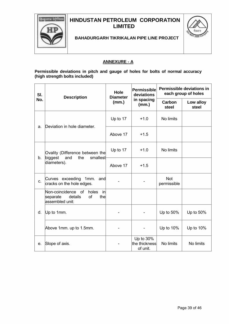
HINDUSTAN PETROLEUM CORPORATION LIMITED
BAHADURGARH TIKRIKALAN PIPE LINE PROJECT
Page 39 of 46
ANNEXURE - A
Permissible deviations in pitch and gauge of holes for bolts of normal accuracy (high strength bolts included)
Permissible deviations in each group of holes Sl.
No. Description
Hole Diameter
(mm.)
Permissible deviations in spacing
(mm.) Carbon steel
Low alloy steel
Up to 17 +1.0 No limits
a. Deviation in hole diameter.
Above 17 +1.5
Up to 17 +1.0 No limits
b. Ovality (Difference between the biggest and the smallest diameters).
Above 17 +1.5
c. Curves exceeding 1mm. and cracks on the hole edges.
- - Not
permissible
Non-coincidence of holes in separate details of the assembled unit:
Up to 1mm. - - Up to 50% Up to 50% d.
Above 1mm. up to 1.5mm. - - Up to 10% Up to 10%
e. Slope of axis. - Up to 30%
the thickness of unit.
No limits No limits

HINDUSTAN PETROLEUM CORPORATION LIMITED
BAHADURGARH TIKRIKALAN PIPE LINE PROJECT
Page 40 of 46
ANNEXURE - B
Tolerance of Assembled Components of Structures
Deviation (±) mm. for elements of structures Sl. No.
Description of components in structures Up to
1m. 1m. to
5m. 5m. to 10m.
10m. to 15m.
15m. to 20m.
20m. to 25m.
Over 25m.
1.
Deviations from the dimensionsassembled.
i.
Length and width of the details cut:
a. Manual gas cutting as per marking 3.0 3.5 4.0 4.5 5.0 - - b. With shears or with saw as per
marking. 2.0 2.5 3.0 3.5 4.0 - -
c. With shears or with a saw with astop.
1.5 2.0 2.5 3.0 3.5 - -
d. Machine gas cutting. 2.0 2.5 3.0 3.5 4.0 - - ii. Length and width of planed
processed on edge planingmachine.
1.0 1.5 2.0 2.5 3.0 - -
2.
i. Distance between centres of the endholes:
a. Drilled according to marking. 2.0 2.5 3.0 3.5 4.0 - - b. Drilled according to a gauge with
bushing. 1.0 1.5 2.0 2.5 3.0 - -
ii. Distance between centres ofadjacent holes:
a. Drilled according to marking or agauge..
1.5 - - - - - -
b. Drilled according to a gauge withbushing.
0.5 - - - - - -
3 Deviation in the dimensions ofdespatch elements after completionof fabrication assembled inpositioners or in other devices withclamps in fixed positioners and also:
a. According to guide blocks with pins. 2.0 3.0 5.0 7.0 8.0 9.0 10.0 b. Assembled with bolts. 3.0 5.0 8.0 11.0 12.0 14.0 15.0 c. Size (length and width) between
milled surface (for all cases ofassembly).
1.0 1.5 2.0 2.5 3.0 3.5 4.0
d. The same made in separate detailsduring machining and fixed duringthe assembly work with clamps.
2.0 3.0 5.0 7.0 8.0 9.0 10.0
e. The same drilled according topositioners in finished structures.
1.0 1.5 2.0 2.5 3.0 3.5 4.0

HINDUSTAN PETROLEUM CORPORATION LIMITED
BAHADURGARH TIKRIKALAN PIPE LINE PROJECT
Page 41 of 46

HINDUSTAN PETROLEUM CORPORATION LIMITED
BAHADURGARH TIKRIKALAN PIPE LINE PROJECT
Page 42 of 46

HINDUSTAN PETROLEUM CORPORATION LIMITED
BAHADURGARH TIKRIKALAN PIPE LINE PROJECT
Page 43 of 46
ANNEXURE - D
Tolerances in Erected Steel Structures
Sl. No.
Description Tolerance
A. COLUMNS 1. Deviation of column axes at foundation top-level w.r.t. true axis a. in longitudinal direction. ±5mm. b. In lateral direction. ±5mm. 2. Deviation in the level of bearing surface of columns at
foundation top w.r.t. true level. ±5mm.
3. Out of plumb of column axis from true vertical axis and measured from column top: a. for columns without any special requirements: i. H ≤ 30m. ±H/1000 or ±25mm. whichever
is less. ii. H > 30m. ±H/1200 or ±35mm. whichever
is less. b. for columns with special requirements like cranes or other similar requirements: i. H ≤ 30m. ±H/1000 or ±20mm. whichever
is less. ii. H > 30m. ±H/1200 or ±25mm. whichever
is less. 4. Deviation in straightness in longitudinal and transverse planes
of columns at any point along the height. ±H/1000 or ±10mm. whichever is less.
5. Difference in the erected position of adjacent pairs of columnsacross length or across width of the building prior to connectingtrusses/beams w.r.t. true distance.
±5mm.
6. Deviation in any bearing or seating w.r.t. true level. ±5mm. 7. Difference in bearing levels of a member on adjacent pair of
columns both across and along the building from the truedifference.
±5mm.
Notes: 1. Tolerance specified under 3.a. and 3.b. should be read in conjunction with 4. and 5. 2. ‘H’ above is the column height in mm.
B. TRUSSES 1 Shift, at the centre of the span of top chord member w.r.t. the
vertical plane passing through centre of the bottom chord. ±1/250 of truss height at centre of span in mm. or ±15mm.whichever is less.
2. Lateral shift of top chord of truss at the centre of span from thevertical plane passing through centre of supports of the truss.
±1/1500 of span of the truss in mm. or ±15mm. whichever isless.
3. Lateral shift in location of truss from its true vertical position. ± 10mm. 4. Lateral shift in location of purlins from true vertical position. ± 5mm. 5. Deviation in difference of bearing levels of trusses or beams
from the true difference.
L/1200 (L is span in mm.) or 20mm. whichever is less.
Notes: 1. The tolerances do not apply to steel structures where deviations from true positions
are intimately linked or directly influenced by technological processes. In such cases,

HINDUSTAN PETROLEUM CORPORATION LIMITED
BAHADURGARH TIKRIKALAN PIPE LINE PROJECT
Page 44 of 46
tolerances on erected steel structures shall be as per recommendations of process technologists/equipment suppliers.
2. The observed or calculated values of deviations of steel structures from their true positions shall be rounded off in accordance with IS: 2-1960 for comparison with permissible tolerances specified in this table. The number of significant places retained in the rounded off value shall be the same as that specified in this table.

HINDUSTAN PETROLEUM CORPORATION LIMITED
BAHADURGARH TIKRIKALAN PIPE LINE PROJECT
Page 45 of 46
ANNEXURE - E
Material of construction (as applicable) 01.00 Unless otherwise specified in the drawing:
a. All rolled sections and plates shall conform to Grade-A as per IS 2062:1992, IS: 8500-1991
b. Plated structures subjected to dynamic loading shall conform to Grade-B as
per IS :2062-1992 c. Plain steel tubes for structural purposes shall be hot finished tubes
conforming to IS 1161:1998(Grade Yst=240).
d. Hollow steel sections shall conform to IS 4923:1997.
e. Expanded metal shall conform to IS 412:1975. f. Steel sheets shall conform to IS 1079:1988.
g. Crane rails shall conform to IS: 3443-1980 02.00 Roof Sheeting & Side Cladding: 02.01 Zincalume high tensile colour coated steel sheet shall be of 0.5mm TCT
and shall have trapezoidal profile with a cover width of 930-1020mm and 28-32mm deep crest at 186-250 c/c with minimum two ribs at centre for stiffening. The sheet shall be made out of steel of minimum fy= 550MPa conforming to AS 1397: 1993. The sheet shall be coated with hot dip metallic zinc aluminium alloy @ 150gsm coating mass total on both sides as per AS 1397: 1993. The colour coating shall be of super polyester XRW or equivalent as per AS/NZS 2728: 1997 Category 3 of approved colour. The zincalume sheet shall have 5μ thick primer coat on both sides of the sheet over which shall be applied 20μ exterior coat on top surface and 5μ reverse coat on inner face. The sheets shall bear manufacturer’s brand marking on the reverse side @ 1m c/c.
2.03 Self-drilling, self-tapping fasteners shall be xylon coated with EPDM
seals conforming to AS: 3566 class III for external fixing and galvanised fasteners with EPDM seals for internal fixing, washers, sealants, neoprene fillers etc.
03.00 Glazing shall be 6mm thick rough cast wired glass as per IS 3548: 1988. 04.00 Gutters shall be of copper bearing steel conforming to IS 2062:1992.
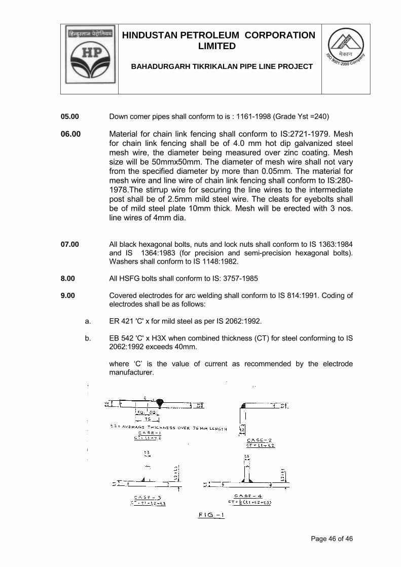
HINDUSTAN PETROLEUM CORPORATION LIMITED
BAHADURGARH TIKRIKALAN PIPE LINE PROJECT
Page 46 of 46
05.00 Down comer pipes shall conform to is : 1161-1998 (Grade Yst =240) 06.00 Material for chain link fencing shall conform to IS:2721-1979. Mesh
for chain link fencing shall be of 4.0 mm hot dip galvanized steel mesh wire, the diameter being measured over zinc coating. Mesh size will be 50mmx50mm. The diameter of mesh wire shall not vary from the specified diameter by more than 0.05mm. The material for mesh wire and line wire of chain link fencing shall conform to IS:280-1978.The stirrup wire for securing the line wires to the intermediate post shall be of 2.5mm mild steel wire. The cleats for eyebolts shall be of mild steel plate 10mm thick. Mesh will be erected with 3 nos. line wires of 4mm dia.
07.00 All black hexagonal bolts, nuts and lock nuts shall conform to IS 1363:1984
and IS 1364:1983 (for precision and semi-precision hexagonal bolts). Washers shall conform to IS 1148:1982.
8.00 All HSFG bolts shall conform to IS: 3757-1985 9.00 Covered electrodes for arc welding shall conform to IS 814:1991. Coding of
electrodes shall be as follows:
a. ER 421 'C' x for mild steel as per IS 2062:1992. b. EB 542 'C' x H3X when combined thickness (CT) for steel conforming to IS
2062:1992 exceeds 40mm. where ‘C’ is the value of current as recommended by the electrode manufacturer.
SPECIFICATION
FOR
INSTALLATION OF INSTRUMENTS
SPECIFICATION NO.: MEC/S/05/26/01
ELECTRICAL & INSTRUMENTATION (OIL & GAS SBU) MECON LIMITED DELHI 110 092
Rev. : 0
Edition: 1

STANDARD SPECIFICATION MECON LIMITED REGD. OFF: RANCHI
834002 ELECTRICAL & INSTRUMENTATION
OIL & GAS SBU, DELHI
INSTALLATION OF DOCUMENT NO. Page 1 of 21
TITLE INSTRUMENTS MEC/S/05/26/01 REVISION : 0
EDITION : 1
AMENDMENT STATUS
Sl. No.
Clause / Paragraph / Annexure / Exhibit / Drawing Amended
Page No.
Revision Date By
(Name)
Verified
(Name)

STANDARD SPECIFICATION MECON LIMITED REGD. OFF: RANCHI
834002 ELECTRICAL & INSTRUMENTATION
OIL & GAS SBU, DELHI
INSTALLATION OF DOCUMENT NO. Page 2 of 21
TITLE INSTRUMENTS MEC/S/05/26/01 REVISION : 0
EDITION : 1
C O N T E N T S
1) SCOPE
2) STANDARDS OF MATERIALS
3) INSTALLATION OF INSTRUMENTS
4) TESTING
5) CALIBRATION OF INSTRUMENTS
PREPARED BY:
(R. SANJAY BABU )
CHECKED BY:
(RAKESH SHUKLA)
APPROVED BY:
(PANKAJ SHIVASTAVA)
ISSUE DATE :
08Th DEC 08

STANDARD SPECIFICATION MECON LIMITED
REGD. OFF: RANCHI 834002 ELECTRICAL & INSTRUMENTATION
OIL & GAS SBU, DELHI
INSTALLATION OF DOCUMENT NO. Page 3 of 21
TITLE INSTRUMENTS MEC/S/05/26/01 REVISION : 0
EDITION : 1
INSTALLATION, TESTING AND CALIBRATION OF
INSTRUMENTATION AND CONTROL SYSTEM 1.0 SCOPE 1.1 The purpose of this specification is to define the general requirements for the
installation, installation materials, testing and calibration of instruments and control system.
1.2 The work shall be carried out in accordance with the codes, standards and
recommended practice listed in this specification and in accordance with local `Statutory regulations'.
1.3 For installation of instruments and control system, of the new material where
quality is of the prescribed standards and which is in every way fit for its intended purpose shall be used.
1.4 Unless otherwise specified all the materials shall be indicated in this specification
except where it is not compatible with fluids being handled. In such cases the selection of the material shall be approved by MECON.
1.5 Only the best trade practices shall be used. All the work shall be carried out in a
neat, workman like manner and to the satisfaction of MECON. 2.0 STANDARDS OF MATERIALS 2.1 Instrument process piping / tubing upto and including the first block valve and
`in-line' instrument equipment shall conform to the line class or vessel rating concerned instrument piping or tubing after the first lock valve may use alternate materials consistent with service conditions. In general they shall conform to the following specification as a minimum.
2.1.1 Stainless tubes shall be fully annealed and cold drawn seam less as per ASTM A
269 TP316 with size 1/2"OD x 0.65" WT (wall thickness). 2.1.2 Monel tubing shall be fully annealed seamless as per ASTM B165 with size 1/2"
OD x 0.35"WT. 2.1.3 Carbon steel pipe shall be 1/2" seamless and shall be as per ASTM A106 Gr B min
of sch 80 & dimensions as per ANSI B36.10. 2.1.4 Seamless stainless steel pipes shall be as per ASTM A 312 Gr TP 316L Sch 80S,
dimensions as per ANSI B 36.19.
STANDARD SPECIFICATION MECON LIMITED
REGD. OFF: RANCHI 834002 ELECTRICAL & INSTRUMENTATION
OIL & GAS SBU, DELHI
INSTALLATION OF DOCUMENT NO. Page 4 of 21
TITLE INSTRUMENTS MEC/S/05/26/01 REVISION : 0
EDITION : 1
2.1.5 Instrument air supply piping from the main instrument air header shall be
galvanised heavy class pipes to IS 1239. 2.2 Individual pneumatic signal and air supply tubing shall conform to the following
specifications: 2.2.1 Stainless tubes shall be used in general and shall be fully annealed and cold drawn
seamless as per ASTM A269 TP 316 with 6mmOD x 1mmWT. 2.2.2 Copper tubing where specified shall be seamless 6mmOD x 1.0mmWT soft
annealed as per ASTM 868.74a cd No. 122 (DHP) sheathed with PVC 1.0mm thick coloured Black.
2.3 All fittings shall be as a minimum of 100 rating except for tube fittings. The fittings
shall have threading as per B2.1 and socket weld connections as per B 16.11. These shall conform to the following specifications in general.
2.3.1 Tube fittings shall be flare type compression fittings Swagelok or equivalents make
double ferrule and pressure seat type. All tube fittings in impulse lines shall be rated to 5000 PSIG at 38oC. 2.3.2 Carbon steel pipe fittings shall be forged as per ASTM A105 stainless steel pipe
fittings shall be as per ASTM –182 Grf 316L 2.4 Valve shall have normally Globe body and shall be fabricated out of Bar-stock and
rated to min. of 1500. These shall be screwed bonnet type with 13% GSS trim and plug shall be integral with the stem. Face to face dimensions shall be approx. 80mm. End connections shall be socket weld to ANSI 16.11 and threaded to B2.1
2.5 Multibore tubing shall have a maximum 19 single polyethylene tubes, 6mmOD x
1mm numbered for easy identification. The bundle shall be marked with inner and outer fire resistance PVC sheath. They shall carry a pair of telephone wire 0.6mm diameter flexible.
2.6 Single pair and multi pair extension cables for Thermocouples shall be matched
and calibrated in accordance with ISA MC 96.1. Conductor size shall be AWG for single pair and 20 A for Multipair.
The cable shall be armoured, each twisted pair shall be individually shielded with
aluminium Mylar tape and a tinned copper drain wire. The wires and the cable shall be colour coded as per ISA recommended practices.

STANDARD SPECIFICATION MECON LIMITED
REGD. OFF: RANCHI 834002 ELECTRICAL & INSTRUMENTATION
OIL & GAS SBU, DELHI
INSTALLATION OF DOCUMENT NO. Page 5 of 21
TITLE INSTRUMENTS MEC/S/05/26/01 REVISION : 0
EDITION : 1
2.7 Instrument Electrical cables shall conform to the following specifications: 2.7.1 Instrument electronic signal cables single pair/ Multipair shall have copper
conductor, twisted in pair and individually shielded with Aluminium Mylar tape with drain wire. In multipair cables, each pair shall be armoured with inner and cut PVC sheath. Minimum conductor size shall be 1.5 mm2.
2.7.2 Control Cables for control signal, alarms actuating devices and solenoid valves of
the interlock and shutdown valves shall generally be 1.5 mm2 copper conductors armoured with inner and cut PVC sheath.
2.7.3 All power supply cables shall have copper/Aluminium conductor depending upon
the conductor size. The cables shall be armoured with inner and cut PVC sheath. The cables shall be sized adequately. Minimum conductor size shall be 2.5 mm2.
2.7.4 2-core armoured cable shall be used for illuminator on level gauges. 2.7.5 The material and construction of all electrical cables shall conform to IS- 1554 Part I or appropriate equivalent code and standard. 3.0 INSTALLATION OF INSTRUMENTS 3.1 Instrument Mounting 3.1.1 No instrument shall be installed in such a way that it bends for support on the
impulse piping or electrical connection on it. 3.1.2 Pressure gauges and temperature indicator shall normally be mounted directly on
line. However direct on line mounting shall be avoided where vibrations are likely to be present.
3.1.3 Local mounted instruments shall be mounted on brackets, panels or placed on a
suitable pedestal. Transmitters shall be mounted on 2” pipe supports where practical. Instruments to be mounted on steel columns, masonary structure etc. These shall not be mounted on heating equipments, pipelines and structures.
3.1.4 Blind transmitters shall be mounted at 130mm above graded platform. Local
controllers, indicating transmitters and indicating instruments shall be mounted at approximately 1500 mm.
3.1.5 All the instruments shall be accessible from grade, ladder or platform etc.
Pressures gauges and other local indicating instruments shall be readable from grade or operating level and if used for manual control shall be visible from the related valve.

STANDARD SPECIFICATION MECON LIMITED
REGD. OFF: RANCHI 834002 ELECTRICAL & INSTRUMENTATION
OIL & GAS SBU, DELHI
INSTALLATION OF DOCUMENT NO. Page 6 of 21
TITLE INSTRUMENTS MEC/S/05/26/01 REVISION : 0
EDITION : 1
All the instruments shall be located such that they don’t impede the process operation.
3.1.6 Local mounted instruments which are not available in weather proof housing shall
be mounted inside a weather proof case. 3.1.7 Items such as pilot valves, solenoid valves etc. shall be located local to its point of
application or near to the device being actuated by them. 3.1.8 For blind transmitters output meters shall be mounted on instrument supports. 3.1.9 Filter regulators shall be mounted on the instrument supports below pneumatic
transmitter or on the control valve yoke. 3.1.10 Instruments or instrument lines shall not be supported on hand rails, in general. 3.1.11 The use of process piping to support instrument lines shall be avoided as far as
possible. 3.1.12 The instrument impulse piping shall be kept as short as possible. 3.1.13 Instruments and impulse lines shall be protected against mechanical damage. 3.1.14 In case of capillary tube instruments, capillary tube is to be supported and
protected against mechanical damage. 3.1.15 Orifice meters shall not be installed on the top of orifice fittings. On horizontal lines
orifice pressure taps shall be located as follows: a) On top for air and gas service b) Horizontal for liquid and condensible vapour service. 3.2 Instrument Piping & Tubing. 3.2.1 Impulse Piping/tubing 3.2.1.1 The primary instrument block valves for all instruments shall be as per piping
specifications. 3.2.1.2 3-Valve manifold in general shall be integral type. For pressure gauges, 2-valve
manifolds shall also be acceptable instead of isolation valve, drain valve and pipe fittings.
3.2.1.3 Differential or static pressure sensing lines shall not exceed 6 mtrs. (20 feet) in
general for direct connected or locally mounted instruments.
STANDARD SPECIFICATION MECON LIMITED
REGD. OFF: RANCHI 834002 ELECTRICAL & INSTRUMENTATION
OIL & GAS SBU, DELHI
INSTALLATION OF DOCUMENT NO. Page 7 of 21
TITLE INSTRUMENTS MEC/S/05/26/01 REVISION : 0
EDITION : 1
3.2.1.4 All impulse lines shall be run with a slope not less than 1 in 12 except where otherwise specified. Direction of slope is to be downward from the process for liquid service and upward from the process for gas service.
3.2.1.5 Tubing shall be joined by compression fittings. 3.2.1.6 Piping shall be joined by pipe fittings/flanges as per the piping specifications. 3.2.1.7 All instruments pipes and tubes shall run in horizontal and vertical planes only and
shall run with minimum number of changes in direction, consistent with good engineering practices and neat appearance.
3.2.1.8 Tubing shall be bent with correct size tube bender as far as possible to avoid use
of fittings. Hot bending shall be totally avoided. Tube cutter shall always be used to cut tubing. The use of short lengths of tubing
in long runs shall be avoided in order to avoid the fittings. 3.2.1.9 All tubing shall run in such a manner as to give the maximum protection against
mechanical damage. Tubing runs shall be grouped together and clamped. 3.2.1.10 Tubing shall be arranged so that the unions can be tightened without distorting
lines. 3.2.1.11 Instrument tubing or piping shall not run on trays intended for cables and shall not
share the same transit. 3.2.1.12 No pipe or tube shall be left with mechanical strain on them. 3.2.1.13 A mechanical ferrule seater shall be used on tubing for 140 kg/cm2 (2000 psi) or
more. 3.2.1.14 Pipe bushings shall not be used. 3.2.1.15 Pipe plugs shall be fabricated out of bar stock and shall have hex-head.
3.2.2 Air/Signal Tubing 3.2.2.1 Signal Transmission tubes shall be laid on perforated trays prefabricated out of min
2.5 mm. thick steel plates. The width of the tray shall be selected as per the number of tubes to be laid.
3.2.2.2 Where tubing is run in permanent enclosures, it should be ensured that entry and
exit of such enclosures is clean and smooth.

STANDARD SPECIFICATION MECON LIMITED
REGD. OFF: RANCHI 834002 ELECTRICAL & INSTRUMENTATION
OIL & GAS SBU, DELHI
INSTALLATION OF DOCUMENT NO. Page 8 of 21
TITLE INSTRUMENTS MEC/S/05/26/01 REVISION : 0
EDITION : 1
3.2.2.3 Tubing run in permanent enclosures shall not have joints, except at special junctions boxes provided for this purpose.
3.2.2.4 Where permanent enclosures are left with space for instrument tubing to be laid at
some later date, a galvanised pull wire of adequate size shall be left in the tray. 3.2.2.5 Where the length of transmission tubing exceeds 60 mtrs (200ft) necessity of
installing signal booster relays shall be considered.
3.2.2.6 In case of `Skidded' equipment or vessels with instrumentation, where off- skid
alarms shutdown or control functions are provided the signal tubes shall be terminated on the control bulk head near the skid boundary.
3.2.3 All threaded pipe joints shall be joined after applying Teflon tape. It should be
applied in a manner to ensure that the tape does not spill over the end of the male fitting. No other pipe joining compound shall be used except on high temperature service where graphite sealing compounds shall be used.
3.2.4 All reasonable precautions shall be taken to prevent foreign materials entering pipe
lines or tubing before and during erection. 3.2.5 Pipes and tubes installed but not connected, shall have the ends clad in approved
fashion to prevent the entry of foreign material. For a period upto one week adhesive tape may be used, for longer periods, caps or plugs shall be used.
3.2.6 Piping/Tubing supports 3.2.6.1 Piping and tubing shall be adequately supported and fixed at a distance not
exceeding that in the following table: Table
----------------------------------------------------------------------------------------------------- Single tubing/Piping Max. distance between supports
----------------------------------------------------------------------------------------------------- 3/8" OD or less Continuous
1/2" to 3/4" Nom. size 2 meters (6ft.)
3/4" to 1" Nom. size 3 meters (9ft.)
Multitube bundle 3 meters (9ft)
---------- -------------------------------------------------------------------------------------------

STANDARD SPECIFICATION MECON LIMITED
REGD. OFF: RANCHI 834002 ELECTRICAL & INSTRUMENTATION
OIL & GAS SBU, DELHI
INSTALLATION OF DOCUMENT NO. Page 9 of 21
TITLE INSTRUMENTS MEC/S/05/26/01 REVISION : 0
EDITION : 1
3.2.6.2 All field mounted instrument air tubing shall be supported with galvanised steel
angles or channels of minimum 1/8" thickness fabricated to present neat appearance.
3.2.6.3 All instruments tubing supports shall be galvanised prior to installation 3.2.6.4 Trays shall be properly supported either from any rigid steel structure or concrete
member. In case of non-availability of above, a suitable support shall be fabricated.
3.3 Instrument Air Supply Distribution 3.3.1 Piping material for instrument main and branched air headers upto the isolation
valve at each take-off from main or branch header shall conform to piping specification.
3.3.2 The air header size shall be established in accordance with the table below, unless
otherwise specified, for a header pressure of 4 to 8.5 kg/cm2
Table – 2 ----------------------------------------------------------------------------------------------------
Max number of users Nominal pipe size ---------------------------------------------------------------------------------------------------- upto 5 1/2" upto 10 3/4" upto 25 1" upto 80 1-1/2" upto 150 2" upto 500 3" --------------------------------------------------------------------------------------------------- 3.2.3 All take off for branch lines are to be from the top of the main header with block
valves equal in size to the branch line. All low point shall have a 1/2" valve installed as a drain and blow down point.
3.3.4 A minimum size of ½” pipe shall be run to the instrument with a ½” valve for each
user. Tubing from the isolation valve to the instrument shall be 6.0 mm. 3.2.5 Union shall be provided at convenient location in the air header. 3.3.6 Filter regulator shall be provided for individual field mounted consumer and shall be
complete with an output gauge. 3.3.7 In case of skid mounted equipments or vessels which incorporate instrumentation
requiring pneumatic supply, on skid supply piping shall terminate at the skid boundary location and size of the supply connections shall be noted on the vendor

STANDARD SPECIFICATION MECON LIMITED
REGD. OFF: RANCHI 834002 ELECTRICAL & INSTRUMENTATION
OIL & GAS SBU, DELHI
INSTALLATION OF DOCUMENT NO. Page 10 of 21
TITLE INSTRUMENTS MEC/S/05/26/01 REVISION : 0
EDITION : 1
approval drawings. 3.4 Installation of multitude and Multicore cables. 3.4.1 Multicore/ Multitube cables shall generally be installed on trays or ducts and
properly clamped. At bends minimum radius shall be maintained as per cable manufacturer’s standards.
3.4.2 All cables shall be rigidly supported on structural steel and masonary. Drilling of
steel member should normally be avoided. However, if the drilling of steel must be resorted to, it must be drilled where minimum of weakening of structure will result cables shall be support at every 500 mm. At every vertical drop these shall be clamped at more frequent intervals max of 300 mm.
3.4.3 Directly buried cables shall be laid underground in excavated cable trenches.
Trenches shall have sufficient depth and width to accommodate all cables correctly spaced and arranged with a view of heat dissipation and economy of design construction of trenches laying of cables and filling up of trenches shall be as per relevant standard.
3.4.4 Each underground cable shall be provided with identifying tag of load securely
fastened every 30 M of its underground length with at least one tag at each end before the cable enters the ground.
Before cables are placed, the trench bottom shall be filled with a layer of sand.
The cables shall be covered with 150 mm of sand on the top of the largest dia. cable tube and sand shall be lightly pressed. A protective covering of 75 mm thick second class red bricks shall be laid flat and the balance portion of the trench shall be filled with soil, compacted and levelled.
3.4.5 At each road crossing and other places where cables enter pipe sleeves, adequate
bed of sand shall be given so that the cables don’t slack and get damaged by pipe ends after back filling.
3.4.6 At the entry into concrete blocks loops shall be provided at either end to prevent
any damage to cable. 3.4.7 The cable entry to control room shall be suitably filled and sealed after laying of
cables so as to achieve a positive sealing against the entry of gas/water. 3.4.8 All wiring, tubing, cables, Junctions boxes and auxiliary equivalent shall be suitably
identified as per applicable codes and practices. All piping and tubing shall be tagged with slip-on or clip on wire marker at both ends.
3.4.9 Jointing of cables is generally not permitted. Cables shall be cut after the exact
site measurements at the cable drums shall be so selected before cutting the lengths as to avoid any unnecessary wastage.
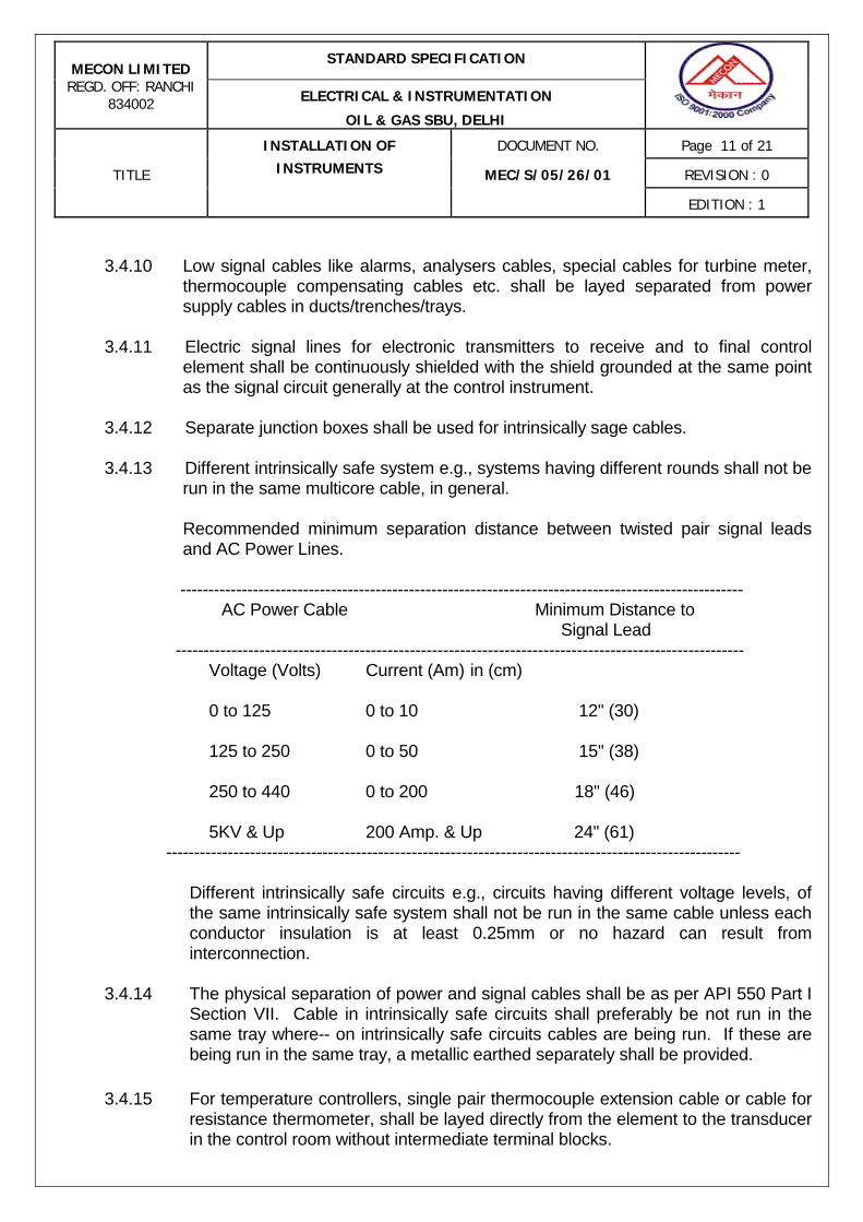
STANDARD SPECIFICATION MECON LIMITED
REGD. OFF: RANCHI 834002 ELECTRICAL & INSTRUMENTATION
OIL & GAS SBU, DELHI
INSTALLATION OF DOCUMENT NO. Page 11 of 21
TITLE INSTRUMENTS MEC/S/05/26/01 REVISION : 0
EDITION : 1
3.4.10 Low signal cables like alarms, analysers cables, special cables for turbine meter,
thermocouple compensating cables etc. shall be layed separated from power supply cables in ducts/trenches/trays.
3.4.11 Electric signal lines for electronic transmitters to receive and to final control
element shall be continuously shielded with the shield grounded at the same point as the signal circuit generally at the control instrument.
3.4.12 Separate junction boxes shall be used for intrinsically sage cables. 3.4.13 Different intrinsically safe system e.g., systems having different rounds shall not be
run in the same multicore cable, in general. Recommended minimum separation distance between twisted pair signal leads
and AC Power Lines. -----------------------------------------------------------------------------------------------------
AC Power Cable Minimum Distance to Signal Lead ------------------------------------------------------------------------------------------------------ Voltage (Volts) Current (Am) in (cm) 0 to 125 0 to 10 12" (30) 125 to 250 0 to 50 15" (38) 250 to 440 0 to 200 18" (46) 5KV & Up 200 Amp. & Up 24" (61) ------------------------------------------------------------------------------------------------------- Different intrinsically safe circuits e.g., circuits having different voltage levels, of
the same intrinsically safe system shall not be run in the same cable unless each conductor insulation is at least 0.25mm or no hazard can result from interconnection.
3.4.14 The physical separation of power and signal cables shall be as per API 550 Part I
Section VII. Cable in intrinsically safe circuits shall preferably be not run in the same tray where-- on intrinsically safe circuits cables are being run. If these are being run in the same tray, a metallic earthed separately shall be provided.
3.4.15 For temperature controllers, single pair thermocouple extension cable or cable for
resistance thermometer, shall be layed directly from the element to the transducer in the control room without intermediate terminal blocks.
STANDARD SPECIFICATION MECON LIMITED
REGD. OFF: RANCHI 834002 ELECTRICAL & INSTRUMENTATION
OIL & GAS SBU, DELHI
INSTALLATION OF DOCUMENT NO. Page 12 of 21
TITLE INSTRUMENTS MEC/S/05/26/01 REVISION : 0
EDITION : 1
3.4.16 In case of skid mounted equipment or equipment which incorporate skid
instrumentation like alarms, shutdown or control function shall terminate signals or control junction box near skid boundary for connection of off skid equipment.
3.4.17 No wire shall be terminated or left with mechanical strain within any conductor. 3.4.18 Splices shall be made only at terminals, in instruments or approval equipment/
junction boxes using lugs and screwed connections. No intermediate splices shall be made in cable trays or in conduct. Number of junction boxes in any cable path shall be limited to only one.
3.5 Installation of Zener barriers
3.5.1 Zener barriers shall be installed in the circuit to make the system intrinsically safe provided:
a) There is no energy storage system in excess to the minimum permitted by the barrier design on the hazardous side of the barrier. The same shall be met by taking intrinsically safe transmitters and selecting the cable electrical parameters like inductance L/R ratio & capacitance in accordance with the maximum parameters given in barrier specifications.
b) No power source exceeding the voltage rating of Zener barrier shall be connected on safe side of the Zener barrier.
c) No outside power source including other intrinsically safe circuits shall be connected to the hazardous side of the barrier.
3.5.2 Zener barriers shall be located as close as possible to the field wiring entry point
in the control room. 3.5.3 Single barrier are bolted directly to copper bus bar and multiple barriers on the
barrier mounting plates. Copper bus or barriers mounting plates shall be isolated from the panel frame.
3.5.4 The signal ground system for intrinsically safe system shall be separate from
power ground system and shall be connected to the signal ground reference point. The maximum resistance allocable between the farthest point on intrinsically safe barrier ground bus and signal ground reference point shall be less than 1 ohm.
3.5.5 Field wires shall directly terminate at the barriers and not through intermediate
terminals.

STANDARD SPECIFICATION MECON LIMITED
REGD. OFF: RANCHI 834002 ELECTRICAL & INSTRUMENTATION
OIL & GAS SBU, DELHI
INSTALLATION OF DOCUMENT NO. Page 13 of 21
TITLE INSTRUMENTS MEC/S/05/26/01 REVISION : 0
EDITION : 1
3.6 Installation of Analyser / Gas Chromatograph 3.6.1 Installation of all analyser shall be in general, as per APIP 550 Part II. 3.6.2 The analyser housing at its installation shall meet all safety requirements as per
classifications. 3.6.3 Sampled process fluid, if not returned to the process shall be disposed to a safe
location. Piping shall be provided so that vapours can be vented to a safe location and liquids shall be drained in a clean and orderly fashion to a safe place. Toxic vapours shall not be vented to atmosphere.
3.6.4 Analyser shall be located as near to the sampling point as possible. 3.6.5 Analyser equipment must be protected from the following: a) Hot equipment b) Severe ambient temperature changes c) Shock d) Mechanical damage e) Vibration 3.6.6 If a separate vent for the analyser is used, the location of that vent shall be in
area of minimum air Turbulence. If the vents of different analysers are vented into a common vent, a back pressure regulator shall be used.
3.6.7 Vent piping shall be designed to prevent condensate from accumulation in low
point and obstruct a free vent flow. 3.7 Ducts, Trays and Supports 3.7.1 Main cable duct shall be of bottom open type with flat/angle --- construction with
side sheet and top cover of 3.2 mm thickness. 3.7.2 The ducts and trays shall be properly supported at regular intervals. Wherever
insert plates are not available, support on concrete structure or ceiling shall be fixed with a minimum of 10 mm expansion bolts Angle supports for ducts shall be fabricated from minimum of 40 mm angle.
3.7.3 All supports shall be neatly cut with hacksaw only and not with gas cutting. Free
ends of angle supports shall not have sharp ends and shall be properly rounded off.
3.7.4 Ducts and supports shall be painted with one coat of Red oxide Zinc chromate
primer conforming to IS-2074 after cleaning to remove scale and then painted with 2 coats of final enamel paint as given below:
STANDARD SPECIFICATION MECON LIMITED
REGD. OFF: RANCHI 834002 ELECTRICAL & INSTRUMENTATION
OIL & GAS SBU, DELHI
INSTALLATION OF DOCUMENT NO. Page 14 of 21
TITLE INSTRUMENTS MEC/S/05/26/01 REVISION : 0
EDITION : 1
a) Duct - Dark admirately Grey as per IS0632. b) Supports - Black.
3.8 Instrument Steam Tracing 3.8.1 Steam for Tracking of instruments shall be taken from main steam header take of
valve through carbon steel pipes supported at regular intervals. 3.8.2 Steam tracing around individual instrument shall be by copper tube of 1/8"
diameter. 3.8.3 Piping or tubing for steam tracing shall be installed in such a way as to avoid
condensate pockets. 3.8.4 After steam tracing, the line is connected to drain funnel through steam trap. 3.9 Identification of Lines and Instruments 3.9.1 All site mounted instruments, junction boxes, air headers, tubing and wiring
terminations shall be labelled or tagged. 3.9.2 Instruments shall be furnished with stainless steel name tags containing Tag no.,
manufacturer’s name, and model no. serial number. This tag number shall be approximately 3"x1" size and shall be attached to the instruments with -- gauge stainless steel wire.
3.9.3 Unused cable entries in junction boxes and field instruments are to be plugged.
4.0 TESTING 4.1 Instrument Impulse piping/Tubing 4.1.1 All process impulse lines shall be disconnected both from the instrument and
vessel/piping end and flushed with water. 4.1.2 After thorough flushing the impulse lines shall be isolated from the instruments
and pressurised hydraulically to 1.5 times the maximum working pressure corrected for ambient temperature. They shall then be isolated from the pressure source and the pressure reading on a test pressure gauge shall not fall at a rate exceeding one psig/hour.
In case no isolation valve is provided near the instrument, impulse piping/tubing
shall be pressurised along with the instrument to the maximum pressure of scale in case of pressure transmitter and max. Operating pressure in case of differential pressure instrument with equalising valve open
STANDARD SPECIFICATION MECON LIMITED
REGD. OFF: RANCHI 834002 ELECTRICAL & INSTRUMENTATION
OIL & GAS SBU, DELHI
INSTALLATION OF DOCUMENT NO. Page 15 of 21
TITLE INSTRUMENTS MEC/S/05/26/01 REVISION : 0
EDITION : 1
4.1.3 In special conditions where hydro- testing is not permissible due to service
requirements, testing shall be carried out by using compressed air/nitrogen. 4.1.4 The external displacer type instruments and cage type level switches shall be
tested to 1.5 times the operating pressure using air/nitrogen after thorough flushing.
4.2 Instrument Air lines/signal tubing. 4.2.1 Instrument air lines/signal tubing shall not be hydrostatically tested. 4.2.2 Instrument air tubing shall be disconnected upstream of all filter regulators and
blown down to remove water, slag and mill scale, from lines at 7.0 kg/cm2 G for fifteen minutes.
Air filter shall be taken in line and tubing shall be disconnected at instrument end,
and blown for 3 minutes to remove traces of dirt. 4.2.3 Testing of instrument air shall be carried out with instrument air at 7 kg/cm2G
upto the upstream of the filter regulator after thorough flushing. All lines shall be checked with soap solution and bubbler unit for possible leak at joints.
4.2.4 All signal tubing shall be checked with 1.5 kg/cm2 after proper flushing. After
pressuring, source shall be cut off and rate of fall in pressure shall be less than IPSL for each 100 feet of tubing for a test period of 2 minutes as per instrument society of American RP 7.1 `Pneumatic Control Circuit Pressure Test'
4.3 Cables 4.3.1 All wiring shall be checked to ensure that it is correctly connected and properly
grounded. 4.3.2 All cables shall be checked for continuity proper connection and insulation
testing. Insulation test shall be carried out on all wiring with a certified magger after
disconnecting the cables at both ends. 4.4 All the results of the above mentioned testing shall be recorded and submitted for
check. 4.5 All the in line instruments like orifice plates, turbine meters, Rotameters, Target
meters, vortex meters, control valves, safety valves etc. shall be removed and spool pieces shall be provided prior to the flushing of the lines.
STANDARD SPECIFICATION MECON LIMITED
REGD. OFF: RANCHI 834002 ELECTRICAL & INSTRUMENTATION
OIL & GAS SBU, DELHI
INSTALLATION OF DOCUMENT NO. Page 16 of 21
TITLE INSTRUMENTS MEC/S/05/26/01 REVISION : 0
EDITION : 1
5.0 CALIBRATION OF INSTRUMENTS 5.1 All instruments shall be calibrated strictly as per manufacturer’s instructions prior
to the installation. In addition to calibration of instruments, setting of safety devices like process switches, safety valves etc. and simulation testing of all interlock and shutdown system shall be carried out.
5.2 In general, all tests shall simulate, as closely as possible, design process
condition by the use of manometers, potentiometers, deadweight testers, test pressure gauges etc. Pour point calibration shall refer to the input signal to an instrument equivalent to 0, 25, 50, 75,100% of instrument range upscale (rising) and 75, 50, 25, 0% of instrument (downscale) (falling).
All instruments unless otherwise noted shall be calibrated in upscale and
downscale direction and if necessary, adjusted until their accuracies conform to those limits state by the manufacturer.
Upon completion of these tests, the instruments shall be drained, completely. 5.3 Temperature Instruments 5.3.1 Temperature Gauges Filled type and Bi metallic dial type Thermometers shall be
four point bench checked for proper operation and calibration using a temperature bath prior to installation.
5.3.2 Temperature Elements and Temperature Transmitters. Temperature Elements and Transmitter shall be four point bench calibrated using
a temperature bath precision meter or precision gauge prior to installation. 5.4 Pressure Instruments 5.4.1 Pressure Gauges 5.4.1.1 Direct connected bourdon type pressure gauges shall be dead weight tested or
tested against a test gauges prior to installation. 5.4.1.2 Receiver type pressure gauges shall be four points calibrated using a precision
gauge and precision air regulator. 5.4.1.3 Pressure and Differential Pressure Transmitters. Pressure and differential pressure transmitters shall be four points calibrated
using a hydraulic or dead weight tester or a precision pneumatic calibrator prior to the installation. A precision output meter or gauge shall be used to monitor the
STANDARD SPECIFICATION MECON LIMITED
REGD. OFF: RANCHI 834002 ELECTRICAL & INSTRUMENTATION
OIL & GAS SBU, DELHI
INSTALLATION OF DOCUMENT NO. Page 17 of 21
TITLE INSTRUMENTS MEC/S/05/26/01 REVISION : 0
EDITION : 1
output. 5.5.1 Orifice plates shall be checked visually for the name plate and for an upstream
sharp edge. Bore dia. shall be checked for compliance with the specification.
5.5.2 Differential pressure type of flow instruments shall be four points calibrated using precision pneumatic calibrator or a manometer and precision regulator. A precision output meter or gauge shall be used to monitor the output of the transmitter.
5.5.3 a) Rotameters shall be installed as received. A check shall be made to confirm that shipping stops have been removed and float has been installed.
b) Where rotameters have transmitting mechanism, the float shall be raised and lowered mechanically and output shall be checked. Vendor calibration data/ curve shall be checked.
C) A check shall be conducted with plumb for a vertical installation. 5.5.4 Turbine meters, Annubar, positive displacement meters, vortex meter, ultrasonic
flow meter, etc. shall be installed as received. 5.5.5 Target meters shall be checked for calibration using calibration weights. Output
shall be monitored using precision output meter. 5.6 Level Instruments 5.6.1 Level Gauge Glasses Gauge glasses shall be installed as received installation of illuminators, frost
protectors and other accessories shall be checked. 5.6.2 Displacer Type, Level Transmitter
- Displacer type level transmitter shall be checked by raising and lowering mechanically the displacement and checking the pilot or transmitter action. Check transmitter with out put gauge or meter for smooth and full output change.
- A check shall be conducted with plumb for a vertical installation. 5.6.3 Differential pressure type level transmitter Differential pressure type level
transmitter shall be calibrated with pneumatic calibrator at four points prior to installation. A precision meter or gauge shall be used to monitor the output of the transmitter.
STANDARD SPECIFICATION MECON LIMITED
REGD. OFF: RANCHI 834002 ELECTRICAL & INSTRUMENTATION
OIL & GAS SBU, DELHI
INSTALLATION OF DOCUMENT NO. Page 18 of 21
TITLE INSTRUMENTS MEC/S/05/26/01 REVISION : 0
EDITION : 1
5.6.4 Tank level gauges a) Tank level gauges shall be checked by raising and lowering mechanically the displacer and checking the indicator on the gauge board. b) Check for proper liquid seal prior to installation in case of liquid seal tank gauges. c) In case of servo type gauges, the displacer is hoisted from the tank into the calibration chamber. 5.7 Control Valves, shutdown valves and self actuated valves 5.7.1 All diaphragm and piston operated control valve shall be stroked pneumatically
using a pressure regulator and pressure gauge against the spring range specified on the name plate of the valve.
5.7.2 Mechanical seating and travel of the valve stem shall be checked against the
side indicator and the name plate 5.7.3 Valve positioner shall be calibrated with the control valve in accordance with the
name plate data and specifications with the help of pneumatic calibrator or gauge with precision regulator. Zero position or fully close position of the valve shall be a live zero i.e., the plug shall be just off the seat at the minimum setting.
5.7.4 Volume bottles, where used shall be checked for proper filling. The signal line
shall be bled to zero pressure and failure action shall be confirmed. 5.7.5 Control valve accessories such as handwheels, boosters, relays etc. shall be
checked operationally. Declutch able handwheel shall be operable both with and without an air signal to the diaphragm.
5.7.6 Self actuated control valves shall be installed as received, checking inlet and
outlet points and name plate data. Regulators with external pressure connections shall be inspected for proper installation.
5.7.7 Butterfly shall be checked carefully to see that the vane moves freely into the
upstream and down stream piping. Proper vane movement to stroke shall be confirmed.
5.7.8 All control valves and regulators shall be removed from the line prior to flushing
and during hydro testing.
STANDARD SPECIFICATION MECON LIMITED
REGD. OFF: RANCHI 834002 ELECTRICAL & INSTRUMENTATION
OIL & GAS SBU, DELHI
INSTALLATION OF DOCUMENT NO. Page 19 of 21
TITLE INSTRUMENTS MEC/S/05/26/01 REVISION : 0
EDITION : 1
5.8 Safety Relief Valves 5.8.1 Safety relief valves shall be installed as received after carefully checking the
name plate data. Pilots, if used, shall be checked carefully for installation on the proper safety valve.
5.8.2 Valves, which are installed in such a manner as to permit on line testing, shall be
pressure tested after installation to determine proper operation and setting. Compressed air or nitrogen shall be used for testing of safety relief valves.
5.9 Switches 5.9.1 Level Switches shall be actuated mechanically for switch operation but shall not
be calibrated for level setting. 5.9.2 Pressure switches shall be calibrated using hydorlic or dead weight tester or
precision air regulator and gauge. The setting/trip point shall be checked using a continuity tester.
5.9.3 Temperature switches shall be calibrated using a temperature both prior to
installation and set to the required alarm/ trip point using a continuity tester. 5.10 Receiver Instruments 5.10.1 Receiver Indicator/Recorders 5.10.1.1 Pneumatic indicators/ Recorders shall be calibrated using pneumatic calibrator/
precision pressure regulator and gauge. 5.10.1.2 Electronics indicators/ Recorders shall be calibrated using a current generator
and a precision meter. 5.10.1.3 Chart drive assembly shall be checked for proper operation. 5.10.2 Controllers 5.10.2.1 Proper balancing of the controller shall be checked as per the manufacturers
catalogues. 5.10.2.2 Controllers shall be checked for manual and Auto operation and Transfer. The
transfer from manual to Auto and vice versa shall be bumpless and smooth. 5.10.3.1 Manual loader station Output of the manual loader shall be checked with a
precision meter.
STANDARD SPECIFICATION MECON LIMITED
REGD. OFF: RANCHI 834002 ELECTRICAL & INSTRUMENTATION
OIL & GAS SBU, DELHI
INSTALLATION OF DOCUMENT NO. Page 20 of 21
TITLE INSTRUMENTS MEC/S/05/26/01 REVISION : 0
EDITION : 1
5.10.4.1 Multipoint Temperature Recorders Each point shall be calibrated using a temperature simulator/ decade box for
RTD / voltage generator and precision meter for the thermocouples. 5.10.4.2 Point synchronisation shall be checked. 5.10.5 Pneumatic receiver switches shall be calibrated using precision air regulator and
gauge. The setting/alarm/trip point shall be checked using continuity tester. 5.10.6 Trip Amplifiers Trip amplifiers shall be calibrated using a temperature simulators
or voltage generator and precision meter for thermocouple or Resistance box for RTD’s. The required setting/ alarm point/ trip point shall be checked using a continuity tester.
5.10.7 Receiver Switch module Receiver switch modules shall be calibrated using a
current source and a precision meter. The required setting/alarm/trip point shall be checked using a continuity tester.
5.10.8 Alarm and Annunciator system 5.10.8.1 Alarm and annunciator system shall be checked for visual and audio alarm
operation using dummy signals. Full alarm sequence of each alarm point shall be checked.
5.10.8.2 Each point shall be checked for proper engraving. 5.10.9 Shutdown System 5.10.9.1 Operation of final actuating elements shall be checked for proper operation using
dummy signals. 5.10.9.2 All timers, push buttons and switches shall also be checked for their proper
operation. 5.11 Analytical Instruments 5.11.1 Check the full analyser system including sample handling system for leakage. 5.11.2 Check the full sample handling system for its proper operation. Calibrate and
check completely all analysers using zero and span samples as per vendor catalogues.

STANDARD SPECIFICATION MECON LIMITED
REGD. OFF: RANCHI 834002 ELECTRICAL & INSTRUMENTATION
OIL & GAS SBU, DELHI
INSTALLATION OF DOCUMENT NO. Page 21 of 21
TITLE INSTRUMENTS MEC/S/05/26/01 REVISION : 0
EDITION : 1
5.12 Flow computer / Volume corrector 5.12.1 Corrected flow values shall be checked for various D.C. inputs and pressure
and temperature variations for upscale and downscale ranges. 5.13 The list of test and calibration instruments with traceability certificates shall be
submitted to MECON for approval before carrying out the tests / calibration of instruments at site.
5.14 The formats / description of tests / calibration of all instruments shall be
submitted to MECON for approval. 5.15 Daily / weekly reports shall be submitted during execution of work at site.
*********************
SPECIFICATION
FOR
INSTRUMENT TUBING
SPECIFICATION NO.: MEC/S/05/26/02
ELECTRICAL & INSTRUMENTATION (OIL & GAS SBU) MECON LIMITED DELHI 110 092
Rev.: 0
Edition: 1
STANDARD SPECIFICATION MECON LIMITED
REGD. OFF: RANCHI 834002 ELECTRICAL & INSTRUMENTATION
OIL & GAS SBU, DELHI
SPECIFICATION FOR DOCUMENT NO. Page 3 of 6
TITLE INSTRUMENT TUBING MEC/S/05/26/02 REVISION : 0
EDITION : 1
AMENDMENT STATUS
Sl. No.
Clause / Paragraph / Annexure / Exhibit / Drawing Amended
Page No.
Revision Date By
(Name)
Verified
(Name)
STANDARD SPECIFICATION MECON LIMITED
REGD. OFF: RANCHI 834002 ELECTRICAL & INSTRUMENTATION
OIL & GAS SBU, DELHI
SPECIFICATION FOR DOCUMENT NO. Page 4 of 6
TITLE INSTRUMENT TUBING MEC/S/05/26/02 REVISION : 0
EDITION : 1
C O N T E N T S 1.0 GENERAL 2.0 CONSTRUCTION 3.0 TESTING 4.0 SHIPPING 5.0 REJECTION
PREPARED BY:
(R. SANJAY BABU )
CHECKED BY:
(RAKESH SHUKLA)
APPROVED BY:
(PANKAJ SHIVASTAVA)
ISSUE DATE :
08Th DEC 08
STANDARD SPECIFICATION MECON LIMITED
REGD. OFF: RANCHI 834002 ELECTRICAL & INSTRUMENTATION
OIL & GAS SBU, DELHI
SPECIFICATION FOR DOCUMENT NO. Page 5 of 6
TITLE INSTRUMENT TUBING MEC/S/05/26/02 REVISION : 0
EDITION : 1
1.0 GENERAL 1.1 Scope 1.1 This standard specifications, together with the data sheets attached herewith,
covers the requirements for the design, materials, testing and shipping of Instrument Tubing which includes the following types:-
a) SS tubes b) Copper tubes 1.1.2 The related standards referred to herein and mentioned below shall be of the
latest edition prior to the date of Purchaser's enquiry: ASTM A 269 - Specification for seamless and welded ferritic
stainless steel tubing for general services. ASTM B 251 - Specification for general requirements for wrought
seamless copper and copper alloy tube. ASTM B 251M - Specification for general requirements for
wrought seamless copper and copper alloy tube (Metric)
ASTM B 68 - Specification for seamless copper tube, bright annealed.
ASTM B 68M - Specification for seamless copper tube, bright annealed. (Metric)
1.1.3 In the event of any conflict between these specifications, data sheets, related
standards, codes, etc., the vendor shall refer the matter to the purchaser for clarifications and only after obtaining the same shall proceed with the manufacture of the items in question.
1.2 Bids 1.2.1 Vendor's quotation shall include a detailed specification sheet for each type of
tube which shall provide the following information: a) All the details regarding the type, construction, materials etc. of the
items. b) Overall the dimensions in mm. 1.2.2 All the units of measurement and material specifications for various parts in the
vendor's specification sheets shall be to same standards as in purchaser's data sheets.
1.2.3 Vendor shall attach a list of items, type wise, summing up all the deviations from this specification and purchaser's data sheets if there are any. Also vendor shall provide reasons for these deviations.

STANDARD SPECIFICATION MECON LIMITED
REGD. OFF: RANCHI 834002 ELECTRICAL & INSTRUMENTATION
OIL & GAS SBU, DELHI
SPECIFICATION FOR DOCUMENT NO. Page 6 of 6
TITLE INSTRUMENT TUBING MEC/S/05/26/02 REVISION : 0
EDITION : 1
1.2.4 Vendor shall enclose catalogues giving detailed technical specifications and
other information for each type of tube in the bid. 1.2.5 Vendor's quotation, catalogues, drawings etc. shall be in English language. 1.3 Drawings, Data and Certification Detailed drawings, data, catalogues and manuals etc. required from the vendor
are indicated by the purchaser in vendor data requirement sheets. The required number of reproducible and prints shall be despatched to the address mentioned, adhering to the time limits indicated.
2.0 CONSTRUCTION 2.1 Stainless Steel Tubes 2.1.1 SS tubes of the tubes shall be Rockwell RB 70-70. Tubes shall be free from
scratches and to be suitable for bending. 2.1.3 Tube wall thickness shall be 0.049" for 1/2" OD and 1mm for 6 mm unless
otherwise specified. 2.1.4 Maximum working pressure shall be 153.0 kg/cm2 at 38oC for 1/2" OD Tube,
unless otherwise specified and 80.0 kg/cm2 at 38o for 6mm OD tube.
2.1.5 Tubes shall be supplied in minimum length of 6 metres without brazing in between.
2.1.6 Dimensional tolerances shall be as per ASTM A 269. 2.1.7 The following shall be marked on the tube: a) Name of manufacturer b) Type and material grade of tube c) Tube O.D. and wall thickness 2.2 Copper Tubes 2.2.1 Copper Tubes (PVC Jacket) 2.2.1.1 The tube shall be soft annealed copper with 6mm OD and a wall thickness of
1.0 mm as per ASTM B 68M Copper No.C12200. 2.2.1.2 The tube shall be jacketed with black PVC. The jacket thickness shall be
1.6mm. The PVC jacket shall confirm to ASTM D-1047.

STANDARD SPECIFICATION MECON LIMITED
REGD. OFF: RANCHI 834002 ELECTRICAL & INSTRUMENTATION
OIL & GAS SBU, DELHI
SPECIFICATION FOR DOCUMENT NO. Page 7 of 6
TITLE INSTRUMENT TUBING MEC/S/05/26/02 REVISION : 0
EDITION : 1
2.2.1.3 The tube ends shall be plugged prior to transportation. 2.2.1.4 The tube shall be of continuous length without any brazing in between for 100
metres length. 2.2.1.5 Minimum length of single tube shall be 100 metres. 2.2.1.6 The dimensional tolerances shall be as per ASTM B 251M. 2.2.2 Bare Copper Tubes (For Steam Tracing) 2.2.2.1 The tube shall be soft annealed copper with 3/8" OD or 6mm OD with a wall
thickness of 1.0 mm as per ASTM B68 copper No.C12200. 2.2.2.2 The tube ends shall be plugged prior to transportation. 2.2.2.3 The tube shall be of continuous length without any brazing in between for 100
metres length. 2.2.2.4 Minimum length of tube shall be 100 metres. 2.2.2.5 The dimensional tolerances shall be as per ASTM B 251. 3.0 TESTING 3.1 The following tests shall be done for SS tubes. a) Hardness test b) Hydrostatic test at 153.0 kg/cm2 at 38o C for 1/2" tube and at 80.0
kg/cm2 at 38oC for 6mm tube, unless otherwise specified. 3.2 PVC jacketed copper tubes shall be tested at 7.0kg/cm2g with dry air for leak
check. 3.3 Bare copper tubes shall be hydrostatically tested at 80.0 kg/cm2g at 38oC. 3.4 Final test before delivery shall include ball test to ensure clear opening of the
tube for copper tubes. The O.D of the ball shall be minimum 1mm for 6mm O.D tube and 2mm for 3/8" tube.
4.0 SHIPPING 4.1 The tubes shall be plugged at both ends to avoid entry of foreign matter. The
tubes shall be packed carefully so as to avoid damage during transport.

STANDARD SPECIFICATION MECON LIMITED
REGD. OFF: RANCHI 834002 ELECTRICAL & INSTRUMENTATION
OIL & GAS SBU, DELHI
SPECIFICATION FOR DOCUMENT NO. Page 8 of 6
TITLE INSTRUMENT TUBING MEC/S/05/26/02 REVISION : 0
EDITION : 1
5.0 REJECTION Vendor shall make his offer in detail, with respect to every item of the
purchaser's specifications. Any offer not conforming to this shall be summarily rejected.
SPECIFICATION
FOR
INLET / OUTLET SECTIONS AND FLOW STRAIGHTENER
SPECIFICATION NO.: MEC/S/05/26/03
ELECTRICAL & INSTRUMENTATION (OIL & GAS SBU) MECON LIMITED DELHI 110 092
Rev.: 0
Edition: 1

STANDARD SPECIFICATION MECON LIMITED
REGD. OFF: RANCHI 834002 ELECTRICAL & INSTRUMENTATION
OIL & GAS SBU, DELHI
SPECIFICATIO FOR DOCUMENT NO. Page 1 of 3
TITLE INLET/ OUTLET SECTIONS AND FLOW STRAIGHTENER MEC/S/05/26/03 REVISION : 0
EDITION : 1
AMENDMENT STATUS
Sl. No.
Clause / Paragraph / Annexure / Exhibit / Drawing Amended
Page No.
Revision Date By
(Name)
Verified
(Name)
STANDARD SPECIFICATION MECON LIMITED
REGD. OFF: RANCHI 834002 ELECTRICAL & INSTRUMENTATION
OIL & GAS SBU, DELHI
SPECIFICATIO FOR DOCUMENT NO. Page 2 of 3
TITLE INLET/ OUTLET SECTIONS AND FLOW STRAIGHTENER MEC/S/05/26/03 REVISION : 0
EDITION : 1
C O N T E N T S 1.0 FLOW STRAIGHTNER 2.0 INLET SECTION/OUTLET SECTION
PREPARED BY:
(R. SANJAY BABU )
CHECKED BY:
(RAKESH SHUKLA)
APPROVED BY:
(PANKAJ SRIVASTAVA)
ISSUE DATE :
08Th DEC 08

STANDARD SPECIFICATION MECON LIMITED
REGD. OFF: RANCHI 834002 ELECTRICAL & INSTRUMENTATION
OIL & GAS SBU, DELHI
SPECIFICATIO FOR DOCUMENT NO. Page 3 of 3
TITLE INLET/ OUTLET SECTIONS AND FLOW STRAIGHTENER MEC/S/05/26/03 REVISION : 0
EDITION : 1
1.0 FLOW STRAIGHTNER
1.1 Flow straightener shall be installed in the inlet section upstream of flow meter. 1.2 Flow straightener shall consist of a bundle of tubes designed and assembled as
per ISO 5167-1980 (E) or AGA Report no.3 or AGA Report no.7. 1.3 Tube diameter shall be 0.2 D or less where D is the diameter of Meter inlet
section pipe. Tube shall be seamless quality of SS 316 material thickness 1.5 or 1 mm Tube shall be hydrostatically tested for 75kg/cm2 pressure and then cut to the required length for assembly.
1.4 On both the sides of tube bundle a very thin retaining rings of SS316 shall be
provided for avoiding the dislocation of pipes. 1.5 The tube bundle shall be kept in position by 6mm threaded bolt. After
tightening the bolt shall seal welded. 1.6 Tube ends shall be tempered at 45o angle. 2.0 INLET SECTION/OUTLET SECTION
2.1 Inlet/Outlet sections of pipe for flow meter shall be of same inside diameter (ID) as turbine meter.
2.2 The pipe used should be circular and with no ovality or any other deformation,
the inside surface of pipe shall be smooth, welded portion shall be grinded to smooth finish.
SPECIFICATION
FOR
INSTRUMENT TUBE FITTINGS
SPECIFICATION NO.: MEC/S/05/26/04
ELECTRICAL & INSTRUMENTATION (OIL & GAS SBU) MECON LIMITED DELHI 110 092
Rev.: 0
Edition: 1

STANDARD SPECIFICATION MECON LIMITED
REGD. OFF: RANCHI 834002 ELECTRICAL & INSTRUMENTATION
OIL & GAS SBU, DELHI
SPECIFICATION FOR DOCUMENT NO. Page 1 of 5
TITLE INSTRUMENT TUBE FITTINGS MEC/S/05/26/04 REVISION : 0
EDITION : 1
AMENDMENT STATUS
Sl. No.
Clause / Paragraph / Annexure / Exhibit / Drawing Amended
Page No.
Revision Date By
(Name)
Verified
(Name)

STANDARD SPECIFICATION MECON LIMITED
REGD. OFF: RANCHI 834002 ELECTRICAL & INSTRUMENTATION
OIL & GAS SBU, DELHI
SPECIFICATION FOR DOCUMENT NO. Page 2 of 5
TITLE INSTRUMENT TUBE FITTINGS MEC/S/05/26/04 REVISION : 0
EDITION : 1
C O N T E N T S 1.0 GENERAL 2.0 CONSTRUCTION 3.0 TESTING 4.0 SHIPPING 5.0 REJECTION
PREPARED BY:
(R. SANJAY BABU )
CHECKED BY:
(RAKESH SHUKLA)
APPROVED BY:
(PANKAJ SHIVASTAVA)
ISSUE DATE :
08Th DEC 08

STANDARD SPECIFICATION MECON LIMITED
REGD. OFF: RANCHI 834002 ELECTRICAL & INSTRUMENTATION
OIL & GAS SBU, DELHI
SPECIFICATION FOR DOCUMENT NO. Page 3 of 5
TITLE INSTRUMENT TUBE FITTINGS MEC/S/05/26/04 REVISION : 0
EDITION : 1
1.0 GENERAL 1.1 Scope 1.1.1 This standard specifications, together with the data sheets attached herewith,
covers the requirements for the design, materials, testing and shipping of instrument tube fittings which includes the following types:-
a) SS compression fittings (SS tube) b) Brass compression fittings (copper tube) 1.1.2 The related standards referred to herein and mentioned below shall be of the
latest edition prior to the date of Purchase's enquiry: ANSI B 2.1 - Pipe Threads B16.11 - Forged steel fittings-socket welding and
threaded. IS:319 - Specification for free cutting brass bars, rods and
sections. ISA RP 42.1 - Nomenclature for instrument tubing - fittings. 1.1.3 In the event of any conflict between these specifications, data sheets, related
standards, codes etc., the vendor shall refer the matter to the purchaser for clarifications and only after obtaining the same shall proceed with the manufacture of the items in question.
1.2 Bids 1.2.1 Vendor's quotation shall include a detailed specification sheet for each type of
tube fittings which shall provide the following information: a) All the details regarding the type, construction, materials, etc. of the
items. b) Overall dimensions in mm. 1.2.2 All the units of measurement and material specifications for various parts in the
vendor's specification sheets shall be to same standards as in purchaser's data sheets.
1.2.3 Vendor shall attach a list of items, typewise, summing up all the deviations from
this specification and purchaser's data sheets if there are any. Also vendor shall provide reasons for these deviations.
1.2.4 Vendor shall enclose catalogues giving detailed technical specifications and
other information for each type of fitting in the bid.

STANDARD SPECIFICATION MECON LIMITED
REGD. OFF: RANCHI 834002 ELECTRICAL & INSTRUMENTATION
OIL & GAS SBU, DELHI
SPECIFICATION FOR DOCUMENT NO. Page 4 of 5
TITLE INSTRUMENT TUBE FITTINGS MEC/S/05/26/04 REVISION : 0
EDITION : 1
1.2.5 Vendor's quotation, catalogues, drawings, etc. shall be in English language.
1.3 Drawings, Data and Certification Detailed drawings, data, catalogues and manuals etc., required from the vendor
are indicated by the purchaser in vendor data requirement sheets. The required number of reproducibles and points shall be despatched to the address mentioned, adhering to the time limits indicated.
2.0 CONSTRUCTION 2.1 SS Tube fittings: 2.1.1 Nomenclature of all tube fittings shall be as per ISA RP 42.1. 2.1.2 Fittings shall be flareless compression type and of three piece construction with
ferrule, nut and body suitable for use on SS tubes conforming to ASTM A 269 TP316, hardness not exceeding RB80.
2.1.3 All parts shall be of SS 316. 2.1.4 Hardness of the ferrules shall be in the range of RB 85-90 so as to ensure a
minimum hardness difference of 5 to 10 between tube and fittings, for better sealing.
2.1.5 Nuts and ferrules of particular size shall be interchangeable for each type. 2.1.6 Spanner hold shall be metric. 2.1.7 Threaded ends of fittings shall be NPT as per ANSI B 2.1. 2.1.8 Copper Tube Fittings 2.2.1 Nomenclature of all tube fittings shall be as per ISA 42.1. 2.2.2 Fittings shall be of flareless compression type and of three-piece construction
consisting of ferrule, nut and body suitable for use on copper tubes conforming to ASTM B 68/B 68M hardnesss not exceeding RB 50.
2.2.3 All parts shall be manufactured from Brass as per IS 319 barstock and Nickel
plated. 2.2.4 For better grip, vendor shall maintain hardness difference between tube &
ferrule and indicate the same along with the offer. 2.2.5 Nuts & ferrules of particular size shall be interchangeable for each type.
STANDARD SPECIFICATION MECON LIMITED
REGD. OFF: RANCHI 834002 ELECTRICAL & INSTRUMENTATION
OIL & GAS SBU, DELHI
SPECIFICATION FOR DOCUMENT NO. Page 5 of 5
TITLE INSTRUMENT TUBE FITTINGS MEC/S/05/26/04 REVISION : 0
EDITION : 1
2.2.6 Threaded ends of fittings shall be NPT as per ANSI B 2.1.
2.2.7 Spanner hold shall be metric. 2.2.8 Vendor shall ensure that the ferrules and nuts supplied for fittings shall be
suitable for sample tube which shall be supplied during manufacture. 3.0 TESTING 3.1 Random samples of SS tube fittings shall be hydrostatically tested as follows:- For 6 mm fittings at 80.0 kg/cm2, 1/2" fittings at 153.0 kg/cm2 at 38oc unless
otherwise specified. 3.2 Random samples of brass compression fittings shall be hydrostatically tested
as follows:- For 1/4" fittings, at 10 kg./cm2, 3/8" at 80.0 Kg/cm2 and all at 38oC. 4.0 SHIPPING 4.1 All thread/ends shall be protected with plastic caps to prevent damage/entry of
foreign matter. 5.0 REJECTION
Vendor shall make his offer in detail, with respect to every item of the purchaser's specifications. Any offer not conforming to this shall be summarily rejected.
SPECIFICATION
FOR
INSTRUMENT VALVES AND MANIFOLDS
SPECIFICATION NO.: MEC/S/05/26/05
ELECTRICAL & INSTRUMENTATION (OIL & GAS SBU) MECON LIMITED DELHI 110 092
Rev.: 0
Edition: 1
STANDARD SPECIFICATION MECON LIMITED
REGD. OFF: RANCHI 834002 ELECTRICAL & INSTRUMENTATION
OIL & GAS SBU, DELHI
SPECIFICATION FOR DOCUMENT NO. Page 1 of 6
TITLE INSTRUMENT VALVES AND
MANIFOLDS MEC/S/05/26/05 REVISION : 0
EDITION : 1
AMENDMENT STATUS
Sl. No.
Clause / Paragraph / Annexure / Exhibit / Drawing Amended
Page No.
Revision Date By
(Name)
Verified
(Name)
STANDARD SPECIFICATION MECON LIMITED
REGD. OFF: RANCHI 834002 ELECTRICAL & INSTRUMENTATION
OIL & GAS SBU, DELHI
SPECIFICATION FOR DOCUMENT NO. Page 2 of 6
TITLE INSTRUMENT VALVES AND
MANIFOLDS MEC/S/05/26/05 REVISION : 0
EDITION : 1
C O N T E N T S 1.0 GENERAL 2.0 CONSTRUCTION 3.0 TESTING 4.0 SHIPPING 5.0 REJECTION
PREPARED BY:
(R. SANJAY BABU )
CHECKED BY:
(RAKESH SHUKLA)
APPROVED BY:
(PANKAJ SRIVASTAVA)
ISSUE DATE :
08Th DEC 08

STANDARD SPECIFICATION MECON LIMITED
REGD. OFF: RANCHI 834002 ELECTRICAL & INSTRUMENTATION
OIL & GAS SBU, DELHI
SPECIFICATION FOR DOCUMENT NO. Page 3 of 6
TITLE INSTRUMENT VALVES AND
MANIFOLDS MEC/S/05/26/05 REVISION : 0
EDITION : 1
1.0 GENERAL
1.1 Scope
1.1.1 This standard specifications, together with the data sheets attached herewith,
covers the requirements for the design, materials, testing and shipping of Instrument Valves & Manifolds which includes the following types:-
a) Miniature instrument valves b) Instrument valve manifolds c) Instrument air valves 1.1.2 The related standards referred to herein and mentioned below shall be of the
latest edition prior to the date of Purchaser's enquiry: ANSI B 2.1 - Pipe threads ANSI B 16.11 - Forged steel fittings-socket welding and threaded. 1.1.3 In the event of any conflict between these specifications, data sheets, related
standards, codes etc, the vendor shall refer the matter to the purchaser for clarifications and only after obtaining the same shall proceed with the manufacture of the items in question.
1.2 Bids 1.2.1 Vendor's quotation shall include a detailed specification sheet for each type of
Valves & Manifolds which shall provide the following information: a) All the details regarding the type, construction, materials etc. of the
items. b) Overall dimensions in mm. 1.2.2 All the units of measurement and material specifications for various parts in the
vendor's specification sheets shall be to same standards as in purchaser's data sheets.
1.2.3 Vendor shall attach a list of items, typewise, summing up all the deviations from
this specification and purchaser's data sheets if there are any. Also vendor shall provide reasons for these in the bid.
1.2.5 Vendor's quotation, catalogues, drawings etc. shall be in English language.
STANDARD SPECIFICATION MECON LIMITED
REGD. OFF: RANCHI 834002 ELECTRICAL & INSTRUMENTATION
OIL & GAS SBU, DELHI
SPECIFICATION FOR DOCUMENT NO. Page 4 of 6
TITLE INSTRUMENT VALVES AND
MANIFOLDS MEC/S/05/26/05 REVISION : 0
EDITION : 1
1.3 Drawings, Data and Certification Detailed drawings, data, catalogues and manual etc. required from the vendor
are indicated by the purchaser in vendor data requirement sheets. The required number of reproducible and prints shall be despatched to the address mentioned, adhering to the time limits indicated.
2.0 CONSTRUCTION 2.1 Instrument Valves (Miniature) 2.1.1 The instrument valves shall be globe pattern-needle valves forged/ barstock
with inside screwed bonnet. 2.1.2 Body and trim material shall be 316 SS unless otherwise specified. 2.1.3 The valve body rating shall be 3000 lbs unless specified in piping material
specification which shall govern in case it is specified. 2.1.4 The end connection shall be 1/2" NPTF to ANSI B2.1. 2.1.5 The packing material shall be teflon unless otherwise specified. 2.1.6 The hand wheel material shall be carbon steel zinc plated. 2.1.7 Flow direction shall be marked on the body. 2.1.8 The valve dimension shall be as follows: a) End to end dimensions 76 mm (approximately). b) Height in fully open condition - 135mm maximum. 2.2 VALVE MANIFOLDS 2.2.1 3-Valve & 5-Valve manifolds: 2.2.1.1 3 Valve manifold shall be designed for direct coupling to differential pressure
transmitters having 2 bolt flanges with 54 mm (2-1/8") centre to centre connections and 41.3 mm (1-5/8") bolt to bolt distance. The manifold shall contain two main block valves and an equalizing by-pass valve. The valves shall be needle valves. They shall use self aligning 316SS ball seats.
2.2.1.2 5 Valve manifold shall contain two main line block valves and a combination
double block and bleed for the bypass line.

STANDARD SPECIFICATION MECON LIMITED
REGD. OFF: RANCHI 834002 ELECTRICAL & INSTRUMENTATION
OIL & GAS SBU, DELHI
SPECIFICATION FOR DOCUMENT NO. Page 5 of 6
TITLE INSTRUMENT VALVES AND
MANIFOLDS MEC/S/05/26/05 REVISION : 0
EDITION : 1
2.2.1.3 The manifold shall be suitably for mounting directly on the stanchion (2" pipe). 2.2.1.4 All bonnets shall have teflon packing unless otherwise specified. 2.2.1.5 The material of construction shall be 316 SS unless otherwise specified. 2.2.1.5 The material of construction shall be 316SS unless otherwise specified.
2.2.1.6 The flanges shall be integral part of the block. 2.2.1.7 The process connection shall be 1/2" NPTF to ANSI B2.1. 2.2.1.8 The manifolds shall be supplied alongwith mounting accessories. The bolts
and nuts shall be alloy steel as per ASTM A 193 Gr B ASTM A 194 GR 2H respectively. Rings shall be teflon and other accessories shall be cadmium plated.
2.2.1.9 Vendor shall furnish the material certificate for body. 2.2.2 3 Way 2 Valve Manifold for pressure gauges. 2.2.2.1 The manifold shall be designed for use with pressure gauges. 2.2.2.2 The valve shall be a ball valve. 2.2.2.3 The body shall be either straight or angle as specified in data sheets. 2.2.2.4 The body and trim material shall be 316SS, packing material shall be teflon
unless otherwise specified. 2.2.2.5 The inlet connection shall be 3/4" plain end (female) for socket weld as per
ANSI B 16.11. 2.2.2.6 The gauge connections shall be with union nut & tail piece threaded 1/2" NPT
(F). 2.2.2.7 The drain connection shall 1/2"NPTF. 2.3 Instrument Air Isolation Valves 2.3.1 The valves shall be full bore ball valves. 2.3.2 Body material shall be Nickel or Cadmium plated carbon steel. 2.3.3 Trim material shall be 316SS.
STANDARD SPECIFICATION MECON LIMITED
REGD. OFF: RANCHI 834002 ELECTRICAL & INSTRUMENTATION
OIL & GAS SBU, DELHI
SPECIFICATION FOR DOCUMENT NO. Page 6 of 6
TITLE INSTRUMENT VALVES AND
MANIFOLDS MEC/S/05/26/05 REVISION : 0
EDITION : 1
2.3.4 The end connection shall be 1/2" NPTF to ANSI B2.1 unless otherwise
specified. 2.3.5 The packing material shall be teflon. 2.3.6 The handle/wrench material shall be cadmium or nickel plated carbon steel. 2.3.7 The valve body rating shall be ANSI 800 lb.
2.3.8 End to end dimensions shall be 70mm (approximately). 3.0 TESTING 3.1 The instrument valves (miniature) shall be hydrostatically tested at 200kg/cm2 g
at 38oC. 3.2 All manifolds (3 valves, 5 valves and 3 ways, 2 valves) shall be hydrostatically
tested at 200 kg/cm2 at 38C. 3.3 The instrument air valves shall be hydrostatically tested at 15.0 kg/cm2g at 38oC
and at 10.5 kg/cm2g with dry air. 4.0 SHIPPING 4.1 All threads/ends shall be protected with plastic caps to prevent damage/entry of
foreign matter. 5.0 REJECTION
Vendor shall make his offer in detail, with respect to every item of the purchaser's specifications. Any offer not conforming to this shall be summarily rejected.

SPECIFICATION
FOR
JUNCTION BOXES AND CABLE GLANDS
SPECIFICATION NO.: MEC/S/05/26/06
ELECTRICAL & INSTRUMENTATION (OIL & GAS SBU) MECON LIMITED DELHI 110 092
Rev.: 0
Edition: 1

STANDARD SPECIFICATION MECON LIMITED
REGD. OFF: RANCHI 834002 ELECTRICAL & INSTRUMENTATION
OIL & GAS SBU, DELHI
SPECIFICATION FOR DOCUMENT NO. Page 1 of 7
TITLE JUNCTION BOXES
AND CABLE GLANDS MEC/S/05/26/06 REVISION : 0
EDITION : 1
AMENDMENT STATUS
Sl. No.
Clause / Paragraph / Annexure / Exhibit / Drawing Amended
Page No.
Revision Date By
(Name)
Verified
(Name)

STANDARD SPECIFICATION MECON LIMITED
REGD. OFF: RANCHI 834002 ELECTRICAL & INSTRUMENTATION
OIL & GAS SBU, DELHI
SPECIFICATION FOR DOCUMENT NO. Page 2 of 7
TITLE JUNCTION BOXES
AND CABLE GLANDS MEC/S/05/26/06 REVISION : 0
EDITION : 1
C O N T E N T S 1.0 GENERAL 2.0 JUNCTION BOXES 3.0 CABLE GLANDS & PLUGS, REDUCERS/ ADAPTORS 4.0 NAME PLATE 5.0 SHIPPING 6.0 REJECTION
PREPARED BY:
(R. SANJAY BABU )
CHECKED BY:
(RAKESH SHUKLA)
APPROVED BY:
(PANKAJ SRIVASTAVA)
ISSUE DATE :
08Th DEC 08

STANDARD SPECIFICATION MECON LIMITED
REGD. OFF: RANCHI 834002 ELECTRICAL & INSTRUMENTATION
OIL & GAS SBU, DELHI
SPECIFICATION FOR DOCUMENT NO. Page 3 of 7
TITLE JUNCTION BOXES
AND CABLE GLANDS MEC/S/05/26/06 REVISION : 0
EDITION : 1
1.0 General 1.1 Scope 1.1.1 This standard specifications, together with the data sheets attached herewith,
covers the requirements for the design, materials, nameplate marking, testing and shifting of junction boxes & cable glands which include the following types:
a) Electrical junction boxes. b) Pneumatic junction boxes c) Cable glands (whenever specified) 1.1.2 The related standards referred to herein and mentioned below shall be of the
latest editions prior to the date of the purchaser's enquiry: ANSI B 2.1 : Pipe threads IS-5 : Colours for ready mixed paints and enamels IS-2147 : Degrees of protection provided by enclosures for Low
voltage switchgear and control gear. IS-2148 : Flame proof enclosure of electrical apparatus. 1.1.3 In the event of any conflict between specifications, data sheets, related
standards, codes etc., the vendor shall refer the matter to the purchaser for clarifications and only after obtaining the same should proceed with the manufacture of the items in questions.
1.2 Bids 1.2.1 Vendor's quotation shall include a detailed specification sheet for each type of
junction box and cable gland which shall provide the following information: a) All the details regarding the type, construction, materials, housing,
entries, etc. b) All dimensions in millimetre. c) Sketch for each type of JB with dimensional details showing the terminal
and entries arrangement. d) Mounting details. e) Vendor shall furnish certificate from statutory body for explosion proof
enclosure, indicating the gas group and temperature class. 1.2.2 All the material specifications for various parts in the vendor's specification
sheets shall be to the same standards as those in purchaser's data sheets (e.g. BS IS, etc.)

STANDARD SPECIFICATION MECON LIMITED
REGD. OFF: RANCHI 834002 ELECTRICAL & INSTRUMENTATION
OIL & GAS SBU, DELHI
SPECIFICATION FOR DOCUMENT NO. Page 4 of 7
TITLE JUNCTION BOXES
AND CABLE GLANDS MEC/S/05/26/06 REVISION : 0
EDITION : 1
1.2.3 Vendor shall attach a list of items, tag number wise, summing up all the deviations from the purchaser's data sheets, if there are any. Also vendor shall furnish reasons for these deviations.
1.2.4 Vendor shall enclose catalogues giving detailed technical specifications and
other information for each type of JB/cable glands and its accessories covered in the bid.
1.2.5 Vendor's quotation, catalogues, drawings, etc. shall be in English language. 1.3 Drawings, Data and Certification 1.3.1 Detailed drawings, data, catalogues required from the vendor are indicated in
vendor data requirements sheets. The required number of reproducible and prints shall be despatched to the address mentioned, adhering to the time limits indicated.
1.3.2 After placement of purchaser order, vendor shall submit certified drawings and
specifications sheets for each type of JB/cable gland which shall include the following:
a) Detailed dimensional drawings b) Weight of each in grams/Kg. c) Certificate from statutory body suitable for installation in specified
hazardous area. 2.1 Junction Boxes 2.0 Junction boxes shall be either of the following type as specified in data sheets. I. Weather proof junction boxes. II. Weather proof & Explosion proof junction boxes. 2.2 The enclosure shall be as per IS-2147 for weather proof junction boxes and for
Explosion proof it shall be as per IS-2148 suitable for the area classification specified.
2.3 Number of entries and locations shall be as per data sheets. 2.4 Junction boxes shall be provided with telephone sockets and plugs for
connection of hand powered telephone set.
STANDARD SPECIFICATION MECON LIMITED
REGD. OFF: RANCHI 834002 ELECTRICAL & INSTRUMENTATION
OIL & GAS SBU, DELHI
SPECIFICATION FOR DOCUMENT NO. Page 5 of 7
TITLE JUNCTION BOXES
AND CABLE GLANDS MEC/S/05/26/06 REVISION : 0
EDITION : 1
2.5 Electrical Junction boxes 2.5.1 Material shall be die-cast aluminium of minimum 5 mm thick (LM-6 alloy) 2.5.2 Explosion proof junction boxes shall have detachable cover which is fixed to the
box by means of cadmium plated triangular head/hexagonal head screws. 2.5.3 Weather proof junction boxes shall have doors which shall be hinged type and
these shall be fixed with cadmium plated countersunk screws. 2.5.4 Explosion proof junction boxes shall have a warning engraved/integrally cast
on the cover as given below: "Isolate power supply elsewhere before opening" 2.5.5 Terminals shall be spring loaded, vibration proof, clip-on type, mounted on
nickel plated steel rails complete with end cover and clamps for each row. 2.5.6 All terminals shall be suitable for accepting minimum 2.5 sq. mm copper
conductor, in general. However for power supply distribution boxes, terminal detail shall be as per job specification/Data sheets.
2.5.7 Sizing shall be done with due consideration for accessibility and maintenance in
accordance with the following guidelines. i) 50 to 60 mm between terminals and sides of box parallel to terminal strip
for upto 50 terminals and additional 25mm for each additional 25 terminals.
ii) 100 to 120mm between terminals for upto 50 terminals and additional 25mm for each additional 25 terminals.
iii) Bottom/top of terminal shall not be less than 100 mm from bottom/top of the junction box.
2.5.8 Terminals shall be marked as per the various types indicated in data sheets. 2.5.9 Shall be provided with external earthing lugs. 2.6 Pneumatic junction boxes 2.6.1 Pneumatic junction boxes shall be made of 3mm thick hot rolled steel. They
shall have necessary neoprene gasket between door and body. Door shall be flush with the box and shall be hinged type and provided with wing nuts.
2.6.2 Single tube entries shall be suitable for 6mm O.D. copper tube with bulk head
fittings. Multi tube bundle entry shall be suitable for the data furnished in data sheets.
STANDARD SPECIFICATION MECON LIMITED
REGD. OFF: RANCHI 834002 ELECTRICAL & INSTRUMENTATION
OIL & GAS SBU, DELHI
SPECIFICATION FOR DOCUMENT NO. Page 6 of 7
TITLE JUNCTION BOXES
AND CABLE GLANDS MEC/S/05/26/06 REVISION : 0
EDITION : 1
2.7 Painting 2.7.1 Surface shall be prepared for painting. It shall be smooth and devoid of rust
and scale. 2.7.2 Two coats of lead-free base primer and two final coats of lead free epoxy
based paint shall be applied both for interior and exterior surfaces. 2.7.3 The colour shall be as specified in data sheets. 3.0 Cable glands & plugs, Reducers/Adaptors 3.1 Cable glands shall be supplied by vendor whenever specified. 3.2 Cable glands shall be double compression type for use with armoured cables. 3.3 The cable glands shall be of Nickel plated brass. 3.4 The cable gland shall be weather proof. Whenever specified they shall be
explosion proof and certificate from statutory body shall be furnished. 3.5 Cable glands shall be supplied to suit the cable dimensions indicated along with
tolerance indicated in data sheets. Various components like rubber ring, metallic ring, metallic cone and the outer/inner nuts etc. shall be capable of adjusting to the above tolerances of cable dimensions.
3.6 Reducers/Adaptors shall be supplied as per details indicated in data sheets.
They shall be nickel plated brass. These shall be weather proof in general. These shall also be explosion proof wherever specified and certificate from statutory body for explosion shall be furnished.
3.7 Plugs shall be provided wherever specified. They shall be of Nickel plated
brass. 3.8 Plugs shall be certified explosion proof when used with explosion and junction
boxes. 4.0 Name Plate 4.1 Each junction box shall have an anodised aluminium name plate permanently
fixed to it at a visible place bearing the tag no. & enclosure. The name plate shall also bear the stamp of certifying agency with certificate number.

STANDARD SPECIFICATION MECON LIMITED
REGD. OFF: RANCHI 834002 ELECTRICAL & INSTRUMENTATION
OIL & GAS SBU, DELHI
SPECIFICATION FOR DOCUMENT NO. Page 7 of 7
TITLE JUNCTION BOXES
AND CABLE GLANDS MEC/S/05/26/06 REVISION : 0
EDITION : 1
5.0 Shipping 5.1 All threaded openings shall be suitably protected to prevent entry of foreign
material. 5.2 All threaded components shall be protected with plastic caps to prevent
damage of threads. 6.0 Rejection Vendor shall furnish his offer in detail, with respect to every item of the
purchaser's specifications. Any offer not conforming to this shall be summararily rejected.

SPECIFICATION
FOR
SIGNAL CABLES
SPECIFICATION NO.: MEC/S/05/26/07
ELECTRICAL & INSTRUMENTATION (OIL & GAS SBU) MECON LIMITED DELHI 110 092
Rev.: 0
Edition: 1
STANDARD SPECIFICATION MECON LIMITED
REGD. OFF: RANCHI 834002 ELECTRICAL & INSTRUMENTATION
OIL & GAS SBU, DELHI
SPECIFICATION DOCUMENT NO. Page 1 of 7
TITLE FOR SIGNAL CABLES MEC/S/05/26/07 REVISION : 0
EDITION : 1
AMENDMENT STATUS
Sl. No.
Clause / Paragraph / Annexure / Exhibit / Drawing Amended
Page No.
Revision Date By
(Name)
Verified
(Name)

STANDARD SPECIFICATION MECON LIMITED
REGD. OFF: RANCHI 834002 ELECTRICAL & INSTRUMENTATION
OIL & GAS SBU, DELHI
SPECIFICATION DOCUMENT NO. Page 2 of 7
TITLE FOR SIGNAL CABLES MEC/S/05/26/07 REVISION : 0
EDITION : 1
CO N T E N T S
1.0 GENERAL 2.0 CONSTRUCTION 3.0 ELECTRICAL CHARACTERISTICS 4.0 TESTING
PREPARED BY:
(R. SANJAY BABU )
CHECKED BY:
(RAKESH SHUKLA)
APPROVED BY:
(PANKAJ SRIVASTAVA)
ISSUE DATE :
08Th DEC 08
STANDARD SPECIFICATION MECON LIMITED
REGD. OFF: RANCHI 834002 ELECTRICAL & INSTRUMENTATION
OIL & GAS SBU, DELHI
SPECIFICATION DOCUMENT NO. Page 3 of 7
TITLE FOR SIGNAL CABLES MEC/S/05/26/07 REVISION : 0
EDITION : 1
1.0 GENERAL 1.1 Scope: This specification together with the job Specifications attached herewith forms
the requirements for design, materials manufacturing, testing and shipping of PVC insulated signal cables.
1.2 Standards: The cables shall conform to the latest editions of the various standards
mentioned in the specification. In case of any conflict between any standard and this - specifications the matter
shall be referred to the purchaser before proceeding with the manufacture of the cables.
1.3 Bids: 1.3.1 Vendor's quotation shall include the following as a minimum. Completed job spec. Pair identification method, type test certificates, technical
literatures, various testing methods and cross sectional dimensional drawings. All information/data shall be in English language.
1.3.2 Vendor's quotation shall include a list of deviations if any from purchaser’s
specifications and shall also indicate the reasons for such deviations for consideration to arrive at mutually agreed deviations. However vendor shall note that no deviation shall be accepted in respect of the permissible limits of resistance capacitance and L/R ratio of cables.
1.3.3 Vendor shall quote unit price per metre for each type of cable. 1.4 Instructions to Bidder: 1.4.1 The quantity indicated against each type of cable in the job specification may
vary by+_ 25% at the time of placement of order. Vendor shall confirm that there shall be no price implication on this account in unit prices typewise.
1.4.2 Drum length for each type of cable shall be 500 to 1000 metres. Vendor shall
indicate the maximum drum length possible for each type of cable in his bid. Exact requirements of drum length will be specified after purchase order during detailed engineering and vendor shall confirm that the same shall not affect the price or delivery schedule. The actual produced drum length shall not vary by more than+_ 5% from the value indicated in the purchase order.

STANDARD SPECIFICATION MECON LIMITED
REGD. OFF: RANCHI 834002 ELECTRICAL & INSTRUMENTATION
OIL & GAS SBU, DELHI
SPECIFICATION DOCUMENT NO. Page 4 of 7
TITLE FOR SIGNAL CABLES MEC/S/05/26/07 REVISION : 0
EDITION : 1
1.4.3 Tolerance over the total ordered length shall be as follows: ± 5% for total length less than 5 km ± 2% for total length 5 km or more 1.4.4 Cable dimensions furnished by vendor in his bid shall be firm. Vendor shall
comply with all the values during execution. 1.5 All cables shall be suitable for laying in open air, corrosive hydrocarbon plant
atmosphere, direct sun and in trenches. The cable shall also be designed for prolonged use in tropical atmosphere.
1.6 On demand vendor shall furnish documents such as invoice and test
certificates to prove the quality and composition of the materials used for manufacturing the cable to the satisfaction of client/ consultant or authorised representative during various stages of expediting and inspection.
2.0 Construction: 2.1 Type 1 (Single pair/triad shielded cable) 2.1.1 Each core shall be 1.5 sq. mm made of 7 stranded annealed electrolytic copper
conductors. Each strand shall be 0.53 mm dia. 2.1.2 Primary insulation shall be 85oC polyvinyl chloride (PVC) as per IS-5831 Type
C. Thickness shall be 0.5 mm minimum. 2.1.3 Each wire shall have twisted cores and No. of twists shall be not less than 10
per metre. Colour of cores insulation shall be black blue in a pair and black, blue and brown in a triad.
2.1.4 Individual pair and triad shall be shielded. Shield shall be Aluminium backed by Mylar/polyester tape bonded together with the metallic side down helically applied with either side - 25% overlap and 100% coverage. Minimum shielded thickness shall be 0.05mm. Drain wire shall be 0.5 sq.mm multistrand bare tinned annealed copy conductor. The drain wire shall be in continuous contact with Aluminium side of the shield.
2.1.5 Inner and outer jacket shall be made of extruded flame retardant 90oC PVC to
IS 5831-Type ST2 Oxygen index of PVC shall be 30. Temp. Index shall be over 250o C.
Inner jacket colour shall be black. Outer jacket colour shall be black except for
cable to be used in intrinsically safe systems it shall be light blue. 2.1.6 Armour over inner jacket shall be of galvanised steel wire/flat as per IS-1554
STANDARD SPECIFICATION MECON LIMITED
REGD. OFF: RANCHI 834002 ELECTRICAL & INSTRUMENTATION
OIL & GAS SBU, DELHI
SPECIFICATION DOCUMENT NO. Page 5 of 7
TITLE FOR SIGNAL CABLES MEC/S/05/26/07 REVISION : 0
EDITION : 1
part-I. 2.1.7 A pair or triad identification shall be with numbers at interval of not more than
250 mm as per vendor's standard. 2.1.8 Tolerance in overall diameter of cable shall be within +_ 2mm over offered
value for cables with OD less than 30mm and+3mm for cables with OD more than 30mm.
2.2 Type-II (Multipair / Multitraid cable with individual pair shield and overall shield) The cable shall be same as single pair shielded cable except conductor size
shall be 0.5 sq.mm made of 16 strands of annealed electrolytic copper conductor. Each strand shall be of 0.2mm dia.
Additional feature shall be as follows: 2.2.1 Overall shield shall be of Aluminium backed up by Mylar/polyester tape helically
applied with the metallic side down either side - 25% overlap and 100% coverage. Minimum shield thickness shall be 0.075mm Drain wire shall be similar to individual pair drain wire and shall be in continuous contact with the Aluminium side of the overall shield.
2.2.2 Overall twist of all pair/triads shall be as per vendor's standard. 2.2.3 A pair of communication wire shall be provided for multipair/multitriad cables.
Each wire shall be 0.5 sq. mm of plain annealed single or multistrand copper conductor with 0.4 mm thick 85oC PVC insulation. Insulation shall be green and red colour coded.
2.3 Type-III (Multipair/Multitriad cable with only overall shield) These cables shall be same as type-II cables except that the individual
pair/triad shall not have shielding. 2.4 Type-IV (Multipair/ multitriad cable with individual pair shield and overall shield) The cable shall be same as Type II except conductor size shall be 1.5 sq.mm
made of 7 stranded annealed electrolytic copper conductor. Each strand shall be 0.53 mm dia.
STANDARD SPECIFICATION MECON LIMITED
REGD. OFF: RANCHI 834002 ELECTRICAL & INSTRUMENTATION
OIL & GAS SBU, DELHI
SPECIFICATION DOCUMENT NO. Page 6 of 7
TITLE FOR SIGNAL CABLES MEC/S/05/26/07 REVISION : 0
EDITION : 1
2.5 Type-V (Multipair/ Multitriad cable with overall shield only)
The cable shall be same as type IV except that the individual pair/triad shall not have the shielding.
3.0 Electrical Characteristics 3.1 Maximum d.c. resistance of the conductor of the completed cable shall not
exceed 12.3 ohms/km at 20o C for cables with 1.5 sq.mm conductor and 39.7 ohms/km at 20oC for cables with 0.5 sq.mm conductor.
3.2 Capacitance 3.2.1 Mutual Capacitance The mutual capacitance of the pairs or adjacent cores shall not exceed a
maximum of 250 pF/Meter at a concequency of 1 KHz.
3.2.2 Capacitance between any core or screen. The capacitance between any core or screen shall not exceed a maximum of
PF/Meter at a frequency of 1KHz. 3.3 L/R ratio of adjacent core shall not exceed 40 micro henry/ohm for cables with
0.5 sq. mm conductor. 3.4 The drain wire resistance including shield shall not exceed 30 ohms/km. 3.5 Electrostatic noise rejection ratio shall be over 76 dB. 4.0 Testing 4.1 Type test: Cable shall be flame retardant to IEC 332 Part III Cat. A. For
qualification certificates from third party or client /consultants authorised representative for this test shall be furnished by vendor for cables similar to those being offered.
4.2 Routine tests: (To be carried out by vendor during various stages of
manufacture. Purchaser shall review the related documentation). 4.2.1 Insulation and jackets: All tests as per IS-5831 except insulation resistance,
voltage and spark test shall be as per BS-5308. Part-II(1986)
STANDARD SPECIFICATION MECON LIMITED
REGD. OFF: RANCHI 834002 ELECTRICAL & INSTRUMENTATION
OIL & GAS SBU, DELHI
SPECIFICATION DOCUMENT NO. Page 7 of 7
TITLE FOR SIGNAL CABLES MEC/S/05/26/07 REVISION : 0
EDITION : 1
4.2.2 Armour test as per IS-3975. 4.2.3 Conductor resistance. 4.2.4 Cable capacitance and L/R ratio.

GENERAL SPECIFICATIONS FOR
INSTRUMENTATION
SPECIFICATION NO.: MEC/S/05/26/08
ELECTRICAL & INSTRUMENTATION (OIL & GAS SBU) MECON LIMITED DELHI 110 092
Rev. : 0
Edition : 1

STANDARD SPECIFICATION MECON LIMITED REGD. OFF: RANCHI
834002 ELECTRICAL & INSTRUMENTATION
OIL & GAS SBU, DELHI
SPECIFICATION FOR DOCUMENT NO. Page 1 of 17
TITLE INSTRUMENTATION MEC/S/05/E5/I/08 REVISION : 0
EDITION : 1
AMENDMENT STATUS
Sl. No.
Clause / Paragraph / Annexure / Exhibit / Drawing Amended
Page No. Revision Date
By
(Name)
Verified
(Name)

STANDARD SPECIFICATION MECON LIMITED REGD. OFF: RANCHI
834002 ELECTRICAL & INSTRUMENTATION
OIL & GAS SBU, DELHI
SPECIFICATION FOR DOCUMENT NO. Page 2 of 17
TITLE INSTRUMENTATION MEC/S/05/E5/I/08 REVISION : 0
EDITION : 1
C O N T E N T S
1.0 GENERAL 2.0 DEFINITIONS 3.0 SCOPE OF WORK 4.0 DESCRIPTION OF WORK 5.0 DRAWINGS AND DOCUMENTS TO BE PROVIDED BY OWNER 6.0 DRAWINGS AND DOCUMENTS TO BE PROVIDED BY CONTRACTOR 7.0 SCRAP AND EXCESS MATERTIAL 8.0 SPECIAL INSTRUCTIONS TO CONTRACTOR
PREPARED BY:
(R. SANJAY BABU )
CHECKED BY:
(RAKESH SHUKLA)
APPROVED BY:
(PANKAJ SRIVASTAVA)
ISSUE DATE :
08Th DEC 08

STANDARD SPECIFICATION MECON LIMITED
REGD. OFF: RANCHI 834002 ELECTRICAL & INSTRUMENTATION
OIL & GAS SBU, DELHI
SPECIFICATION FOR DOCUMENT NO. Page 3 of 17
TITLE INSTRUMENTATION MEC/S/05/E5/I/08 REVISION : 0
EDITION : 1
1.0 GENERAL 1.1 INTRODUCTION 1.1.1 This part of the technical specifications covers in general, definitions,
standards, scope of works, specifications of work, documentation, scope of supply of materials and scrap and excess materials and different requirements to be adhered to during the course of execution of instrumentation works.
1.1.2 Instrumentation works shall be performed in accordance with this technical
specification and various other drawings and schedules supplied during the execution and time to time instructions from Engineer-in-Charge or his authorised representative(s) during the progress of the work.
2.0 DEFINITIONS 2.1 MANIFOLDS 2.1.1 For close coupled instruments "Manifold" shall mean complete piping of
instruments from first block valve upto the instruments, if the distance of the Instrument is within 2 feet (0.6m), from the Instrument tapping. If the distance of instrument is more than 2 feet (0.6m) from primary tapping such as orifice, then the installation is to be considered under remote installation.
2.1.2 For remote mounted instrument, "Manifold" shall mean the assembly of nipples,
valves and fittings around the instrument to form a block and bleed or by pass manifold or drain manifold as the case may be. These shall be generally according to the hook up drawings enclosed with tender. Wherever the instruments are with 3--way-valve manifold, this definition shall not be applicable as 3-way manifold forms part of instrument.
2.2 FIRST BLOCK VALVE First block valve shall mean the valve/valves that are mounted directly on
equipment, columns, pipe, standpipe etc. and shall be operated to isolate the instrument and connected instrument piping from the above items.
2.3 SUPPORTS Supports shall mean the MS angles, flats, channels that are generally provided
to support the main cable ways, cable ducts, junction boxes, angle trays, perforated trays, instrument piping, signal tubing, instrument air supply lines etc., at specified intervals from the structures, concrete columns etc. to keep all items firmly secured against vibration, warping, bending etc.

STANDARD SPECIFICATION MECON LIMITED
REGD. OFF: RANCHI 834002 ELECTRICAL & INSTRUMENTATION
OIL & GAS SBU, DELHI
SPECIFICATION FOR DOCUMENT NO. Page 4 of 17
TITLE INSTRUMENTATION MEC/S/05/E5/I/08 REVISION : 0
EDITION : 1
2.4 SCRAP
2.4.1 Salvageable scraps Salvage scrap shall mean lengths of tubes, pipes, multicables, other cables etc.
that can be used one time or other at later date and normally they are recovered from the cut-pieces of tubes, pipes, multicables, cables, etc.
2.4.2 Non Salvageable Scrap Non salvageable scrap shall mean the lengths of tubes, pipes, multicables,
cables, etc. that cannot be used at all one time or other. 2.5 Standards The instrumentation erection and calibration works shall be carried out
generally in accordance with various international and Indian standards in instrumentation listed below but not limited to the following:
2.5.1 API -RP-550 Manual on Practices for instrumentation. 2.5.2 ISA standards and Practices for instrumentation 2.5.3 Instrumentation hook-up standards enclosed. 2.5.4 Instrumentation supports standard enclosed. 2.5.5 Manufacturer's standards and Practices. 3.0 SCOPE OF WORK 3.1.0 The Scope of work shall consist of supply of instrument items (as per schedule
of quantities/rates and SCC), instruments, their erection, testing, calibration and commissioning and making it ready for commercial operation. The scope covers various jobs listed under the schedule of quantities/rates. However to ensure proper execution and completeness of instrument--work any or all of the following shall also form the part of the scope and shall be covered in the quoted rates.
3.1.1 Fabrication of pipe nipples, including threading whenever required. 3.1.2 Fabrication of seal pot/syphon/drain pot as per standards. Filling of seal pots
with filling liquids as per instructions from Engineer-in-charge. 3.1.3 Back/seal welding of screwed fittings as required by standards.
STANDARD SPECIFICATION MECON LIMITED
REGD. OFF: RANCHI 834002 ELECTRICAL & INSTRUMENTATION
OIL & GAS SBU, DELHI
SPECIFICATION FOR DOCUMENT NO. Page 5 of 17
TITLE INSTRUMENTATION MEC/S/05/E5/I/08 REVISION : 0
EDITION : 1
3.1.4 Laying of cable underground including excavation, sand filling, brick laying and back filling.
3.1.5 Connection of purging devices for instruments to the systems provide as per
drawings. 3.1.6 Civil works including the casting of foundation as per requirements for
instruments supports where paved surface do not exist. 3.1.7 Minor civil works like chipping of pavement and grouting on the pavements the
instrument panels/supports/stanchions, and chipping and refilling of the pavement for conduits.
3.1.8 Sealing of cables/ tube entries into the control room after laying and testing of
all tubes, cables etc. 3.1.9 Degreasing of handwheels of control valves, stud bolts, nuts of side and bottom
flange of control valves, orifice plates, other primary elements flanges, oxygen service impulse lines, instruments as per manufacturers instructions and other items as required by Engineer- in-charge.
3.1.10 Rotation of control valve bonnet wherever required. 3.1.11 Reversing the action of control valves either the replacement of springs,
accessories or in positioner wherever required. 3.1.12 Minor modification/repairs required to be done on the instruments namely,
changing the dial, glasses for pressure gauges, temperature gauges and other instruments, replacement of rotameter tubes, level gauge glasses, replacement of damaged signal tubes, threads, couplings etc.
3.1.13 Painting of all structural supports for trays, pipes, junction boxes, instruments,
etc, as per painting specification. 3.1.14 Identification with approved colour of paint the instruments/impulse, lines
manifold connected with alarm/trap circuit. Also, punching of tag numbers on items shall be carried out as per instructions of Engineer-in-charge.
3.1.15 Coordination with mechanical and other sub-contractors for proper installation
of line/ vessels/ equipment mounted instruments like control valves, orifice assemblies, turbine meters, PD meters, level transmitters, level gauges, level switches etc. which involves removal of instruments, disconnection of tubes/cables, reconnection for alignment proper installation etc.
3.1.16 Drilling holes on all panels, shut down cabinets, power supply cabinets, control panels pneumatic enclosures etc., for cables/ multitubes/ glands/ groomats.
STANDARD SPECIFICATION MECON LIMITED
REGD. OFF: RANCHI 834002 ELECTRICAL & INSTRUMENTATION
OIL & GAS SBU, DELHI
SPECIFICATION FOR DOCUMENT NO. Page 6 of 17
TITLE INSTRUMENTATION MEC/S/05/E5/I/08 REVISION : 0
EDITION : 1
3.1.17 Grounding of shield of all shielded cables to respective instruments earth bus provided in the control room/local panel/thermocouple head.
3.1.18 Laying and termination at both ends between instrument earth buses provided
in control room/ local panel to instrument earth pit provided by others. 3.1.19 Supply of all types of consumables required for the execution of the job. 3.1.20 Submission of monthly material appropriation statements for cables, piping
materials fittings, including the quantity issued and expended in standard proforma.
3.1.21 Completion of owners drawings/documents, as per the execution of work at
site. 3.1.22 Preparation and submission of as built drawings as required. 3.1.23 Start-up and commissioning. 3.1.24 Submission of final material appropriation statements for all the materials
issued by the owner. 3.1.25 Any other work not mentioned above, but required for the proper execution of
the works. 3.1.26 Where requested by owner/Engineer-in-charge or his authorised
representatives, all or any of the works detailed above and schedule quantities shall also be performed on package units, local panels/cabinets/gauge board installed by owner or by others.
3.1.27 Sealing of safety valves/switches with standard lead seals after final setting in
the presence of Engineer- in-charge. 4.0 DESCRIPTION OF WORK 4.1.0 INSTRUMENT PIPING 4.1.1 All primary piping shall be installed in the best workman like manner and shall
follow installation standards in each case. Where there is no installation standard, the instruction of the Engineer-in-charge shall be followed.
4.1.2.1 Horizontal and vertical lines shall be installed using levels and plumo bobs.
4.1.3 Unless otherwise specified in the drawings pipelines shall have a slope of 8% on the horizontal runs.

STANDARD SPECIFICATION MECON LIMITED
REGD. OFF: RANCHI 834002 ELECTRICAL & INSTRUMENTATION
OIL & GAS SBU, DELHI
SPECIFICATION FOR DOCUMENT NO. Page 7 of 17
TITLE INSTRUMENTATION MEC/S/05/E5/I/08 REVISION : 0
EDITION : 1
4.1.4 All welding shall be carried out as per welding procedures and codes with
electrodes approved by Engineer-in-charge. Only qualified welders approved by Engineer-in-charge shall carry out welding. Charges for non-destructive testing like radiography, Dye penetration tests, post heat treatment tests and stress relieving shall be carried out on the basis of actual man hours spent towards these works and man-hour charges with cost of all materials, test equipments, etc. shall be used. However, any materials like electrode, equipments, testing charges for various tests, etc., required for the initial qualification of the welder/welders shall be or the scope of the contractor.
4.1.3.1 Pipe shall be bent using pipe benders only and any bending will be totally
rejected. Pipes shall be cut using pipe cutting device. Hot cutting will not be allowed.
4.1.6 Piping for steam tracing shall be installed according to the standards and
avoiding condensate pockets. 4.1.7 All threaded joints shall be jointed with Teflon tape and no other pipe jointing
compound shall be used except on high temperature service where graphited sealing compounds shall be used.
4.1.8 All primary piping shall be properly supported at regular intervals of 1.0 meters.
Angle supports shall be fabricated from 40mmx40mmx5mm MS angles as minimum.
4.2.0 PVC COVERED/BARE TUBE (COPPER/SS/ALUMINIUM) 4.2.1 Single copper/SS/Aluminium tubes shall be laid as per standards on trays.
Fabricated out of 2.5 mm thick perforated steel plate. The width of the trays shall be selected as per the number of tubes laid. Tubes shall be clamped to the trays at every 300 mm using clamps made of galvanized steel/Aluminium strips. The practice of flattening tubes for clamping purposes shall be avoided. In case of PVC covered tubes, any exposed portion at ends and connection shall be neatly taped to appropriate thickness.
4.2.2 Trays shall be properly supported either from any rigid steel structure or
concrete member as detailed under trays and supports below. 4.2.3 All male/female tube connectors shall be installed with Teflon tape only.
Identification tag plates/ferrules shall be provided on either side of copper tubing as per tubing/junction box schedules. Ferrules shall be single sleeve type with letters and numbers neatly printed.
STANDARD SPECIFICATION MECON LIMITED
REGD. OFF: RANCHI 834002 ELECTRICAL & INSTRUMENTATION
OIL & GAS SBU, DELHI
SPECIFICATION FOR DOCUMENT NO. Page 8 of 17
TITLE INSTRUMENTATION MEC/S/05/E5/I/08 REVISION : 0
EDITION : 1
4.3.0 INSTALLATION OF MULTITUBES AND MULTICORE CABLES 4.3.1 Multiple cables/ multitubes shall always be installed on ducts/trays and properly
clamped. At every vertical drop to junction boxes, they shall be clamped at more frequency intervals (Maximum of 300mm). They shall be connected inside junction boxes strictly according to the number system as mentioned in cable schedule. At bends minimum radius shall be maintained as per manufacturer's standard. The angle tray supports shall be fabricated from 40mmx40mmx5mm angles minimum size.
4.3.2 Identification tags shall be provided on either end of multitubes, multicore
cables as per cable/tubing/cable schedules. Engraved tag plates or PVC ferrules shall be used for identification of tubes/cables.
4.3.3 All Multitubes and Multicables shall be cut after the exact site measurements are taken between ends and the cable/tube drums shall be selected before cutting the lengths so as to avoid any wastage.
4.3.4 In the field, the cables shall be laid in perforated trays as per layout drawings.
Cables shall also be buried or laid in concrete trenches. Inside control room, these shall be laid in concrete trenches or under false floorings.
4.3.5 In the field, the cables shall be laid in perforated trays as per layout drawings.
Cables shall also be buried or laid in concrete trenches. Inside control room, these shall be laid in concrete trenches or under false floorings.
4.4.0 INSTALLATION OF INSTRUMENTS 4.4.1 All instruments shall be generally installed on supports as per installation
standards in each case, and shall be accessible. 4.4.2 Receiver gauges shall be mounted on instrument support itself as per tubing
hook up standards. 4.4.3 Filter regulators shall be mounted on the instruments support itself below the
instruments or on the control yoke. 4.5.0 INSTRUMENT AIR SUPPLY 4.5.1 The main instrument air header in each area is laid by other contractor. Air
supply from the main air header take off valve to individual instrument shall be through either galvanized steel pipe or 1/4" OD PVC covered copper tube or SS tubes.
4.5.2 Individual takes off valves shall always be located on top of the main air header.
Unions shall be provided at convenient locations. There shall be one isolation valve at each instrument end. The galvanised pipe shall be supported at a
STANDARD SPECIFICATION MECON LIMITED
REGD. OFF: RANCHI 834002 ELECTRICAL & INSTRUMENTATION
OIL & GAS SBU, DELHI
SPECIFICATION FOR DOCUMENT NO. Page 9 of 17
TITLE INSTRUMENTATION MEC/S/05/E5/I/08 REVISION : 0
EDITION : 1
minimum interval of 1000 mm with 40mmx40mmx5mm MS angles. Final connection to be instrument shall be copper/SS tubing as per tubing hookup standards.
4.5.3 Teflon tapes shall be used on all threaded joints. 4.6.0 INSTRUMENT STEAM TRACING 4.6.1 The mainsteam header in each area is laid by the other contractor. From the
main steam header take off valve, steam to individual instrument shall be taken through carbon steel pipes supported at regular intervals. Steam tracing around individual instruments shall be to copper tubes. After steam tracing, the line is connected to the drain funnel through individual steam trap/condensate return header/tapper point as the case may be.
4.6.2 Electrical tracing shall be done by others. 4.7.0 PERFORATED TRAYS AND SUPPORTS 4.7.1 The perforated trays / angle trays shall be properly supported at a regular
interval of max. 1000mm from insert plates or steel structures. Wherever insert plates are not available supports on concrete structures on ceiling shall be fixed with a minimum 10mm diameter expansion bolts. Angle supports for perforated trays/angle trays shall be fabricated from 40mmx40mmx5mm M.S. angles minimum size.
4.7.2 All supports shall be cut with hacksaw and any work executed by gas cutting for
cutting and drilling holes will be totally rejected. Free ends of angle support shall not have sharp edges and shall be properly rounded off.
4.7.3 Perforated trays/angle trays shall be used for branching cables and tubes from
main trays. Perforated trays shall be used for branching cables and tubes from main trays. Perforated trays shall be fabricated out of 2.5 mm perforated steel sheet. Width of trays shall be selected according to number of tubes and cables. Trays shall be laid generally as per site conditions with the approval of Engineer-in-charge.
4.8.0 LAYING OF CABLES 4.8.1 All cables shall be laid in accordance with installation drawings and cable
schedules. Before laying, cable/multicable on drums shall be meggered and tested to ascertain the transit damages.
4.8.2 All cables routes shall be carefully measured and cables cut to the required
lengths, leaving sufficient amount for the final connection of the cable to the terminals on either end. The various cable lengths cut from the cable reels shall be carefully selected to prevent undue wastage of cables. Sufficient extra

STANDARD SPECIFICATION MECON LIMITED
REGD. OFF: RANCHI 834002 ELECTRICAL & INSTRUMENTATION
OIL & GAS SBU, DELHI
SPECIFICATION FOR DOCUMENT NO. Page 10 of 17
TITLE INSTRUMENTATION MEC/S/05/E5/I/08 REVISION : 0
EDITION : 1
length of cable shall be kept at the terminal on points. 4.8.3 Cables shall have complete uncut lengths from one terminal to the other. 4.8.4 All cables shall be identified close to their termination point by cables number
as per cable schedules/junction boxes schedules. PVC ferrule/tag plate shall be used and these identification tags shall be securely fastened to the cables.
4.8.5 All cores of electrical cables shall be identified by their wire numbers by means
of the PVC ferrules. Wire numbers shall be as per schedules. All temporary ends of cables shall be protected against dirt and moisture. For this purpose, ends of all PVC insulation cables shall be taped with an approved PVC or rubber insulating tape. Use of function type or other fabric type is not permitted.
4.8.6 The cable shall be bent in a large radius. Cables installed above ground shall
be run exposed on walls, ceilings, structures and shall run parallel or at right angles with beams, walls or columns.
4.8.7 Cables shall be rigidly supported on structural steel and masonary individually
or in groups as required using galvanised clips, multiple cable supports or cable trays. If drilling of steel must be resorted to, approval must be obtained and steel must be drilled where the minimum of weakening of the structure will result. Cable shall be supported at every 500 mm.
4.8.8 All special cables and power supply cables will be laid directly to the field instrument without any junction boxes, unless otherwise specified.
4.8.9 While laying cable in trenches or burying them care shall be taken to ensure
that low signal cables like alarm, analyser cables, special cables, special cables from turbine meters, compensating cable etc. are separated from other power supply cables.
4.8.10 Each underground cable (either in concrete trenches or burried) shall be provided with identifying tag of lead securely fastened every 30m of its underground length with atleast one tag at each end before the cable leaves/enters the ground.
4.8.11 Directly buried cables shall be laid underground in excavated cable trench wherever specified in layout drawings. Trenches shall have sufficient depth and width to accommodate all cables correctly spaced. Before cables are placed the trench bottom shall be filled with 100 mm layer of sand and leveled. Each layer of cables shall be covered with 150 mm of sand on top and sand shall be lightly pressed. A protective covering of 75 mm thick second-class red bricks shall be placed flat on the final layer of sand and cable. The remaining portion of the trench shall be then back filled with soil compacted and leveled. On complete of every group of cable laying and before sand filling, every cable shall be given insulation test in the presence of Engineer-in-charge. Any cable proved to be defective should be replaced before the next groups of cables are laid. Cable route markers indicating number of cables, depth and direction will
STANDARD SPECIFICATION MECON LIMITED
REGD. OFF: RANCHI 834002 ELECTRICAL & INSTRUMENTATION
OIL & GAS SBU, DELHI
SPECIFICATION FOR DOCUMENT NO. Page 11 of 17
TITLE INSTRUMENTATION MEC/S/05/E5/I/08 REVISION : 0
EDITION : 1
be placed enroute, on crossovers/turnings, etc. to mark the cable route. 4.8.12 At each road crossings and other places, where cables enter pipe sleeves,
adequate bed of sand shall be given so that the cables do not slack and get damaged by pipe ends after pack filling.
4.8.13 At the entry into concrete blocks at road crossings cable loops shall be provided
at either end to prevent any damage to cables. Each cable shall have one tag at each end before the cable enters/leaves conduct pipes
4.8.14 After laying of all the cables and multitubings, cables, the cable entry to control
room shall be suitably filled and sealed so as to achieve a positive seal against the entry of gas/water.
4.8.15 All cables and tubes shall be laid in accordance with the layout drawings with sand and precast concrete slabs shall be placed on the trench.
4.8.16 On completion of cable laying in concrete trenches, the trenches shall be filled with sand and precast.
4.9.0 EARTHING 4.9.1 Earthing of junction boxes, local cabinets as per the documents and instruction
from Engineer-in-charge. 4.10.0 PAINTING 4.10.1 This part of the specification is applicable to cable ducts, MS cable ways, angle
trays, instrument supports, perforated trays, all structural supports for the above items, etc.
4.10.2 The surface to be painted shall be thoroughly cleaned with wire brush, sand
paper to remove all scales. After cleaning, the surface is painted with one coat of red oxide zinc chromate primer conforming to IS- 207 and allowed to dry completely.
4.10.3 Primer coated surface is painted with one coat of paint to the colour nearest to
the final paint and allowed to dry. The colour number shall be specified from IS-5.
4.10.4 Final second coating shall be with the paint of desired colours and shall be
selected from IS-5. 4.10.5 It shall be noted that final second coating of external surfaces not covered by
cables, copper tubes etc. shall be applied just before handling over the plant or commissioning of the plant whichever is earlier.
4.10.6 The name of manufacturer, colour and quality of all types of primer paint shall
STANDARD SPECIFICATION MECON LIMITED
REGD. OFF: RANCHI 834002 ELECTRICAL & INSTRUMENTATION
OIL & GAS SBU, DELHI
SPECIFICATION FOR DOCUMENT NO. Page 12 of 17
TITLE INSTRUMENTATION MEC/S/05/E5/I/08 REVISION : 0
EDITION : 1
be subject to approval of Engineer-in-charge. 4.11.0 TESTING 4.11.1 Electrical cables for signal power supply alarms, and compensating cables for
thermocouples; resistance thermometer cables shall be checked for megger values and continuity before proper termination and ferruling.
4.11.2 Testing shall be carried out after the installation of instrument with primary
piping complete in all respects and approved by Engineer-in-charge. 4.11.3 Primary piping shall be tested hydraulically pneumatically to 1.5 times the
operating pressure after isolating the instruments. Flushing of piping shall be carried out as per instructions of Engineer-in-charge. Lines shall be blown after hydro-testing. All external displacement /float type level instrument level gauges shall also be tested as per instructions of Engineer- in-charge.
4.11.4 Tubes and air line shall be tested with compressed air to 7 kg/cm2 upto the filter
regulator. The down steam side of the filter regulator shall be tested for 1.5kg/cm2. The lines shall be blown with the instrument air upto the regulator for 15 minutes to remove any traces of oil, dust & moisture. All lines shall be checked with soap solution and bubbler unit for possible leak at joints. After pressurizing, source shall be cut off and rate of fall in pressure shall be less than 1 p.s.i. for each 100 ft. of copper tubing for a test period of 2 minutes as per I.S.A.R.P.7-1 "Pneumatic control circuit pressure test".
4.11.5 All test results shall be recorded in the approved format. 4.12.0 CALIBRATION 4.12.1 All instruments shall be calibrated strictly as per manufacturer's instructions
prior to installation. The scope of calibration includes all field and control rooms of all types namely, pneumatic, electronic, electrical etc.
4.12.2 Contractor shall use his own oil free instruments, air compressor for calibration
purposes. 4.12.3 The level switches (external cage type) shall be set by filling the cage with
water to the desired alarm/trip level, while setting the switches, it shall be ensured that the micro switches do not reset for full rated travel of the float.

STANDARD SPECIFICATION MECON LIMITED
REGD. OFF: RANCHI 834002 ELECTRICAL & INSTRUMENTATION
OIL & GAS SBU, DELHI
SPECIFICATION FOR DOCUMENT NO. Page 13 of 17
TITLE INSTRUMENTATION MEC/S/05/E5/I/08 REVISION : 0
EDITION : 1
4.12.4 Control valves and positioners shall be checked for hysterisis and linearity and calibration for rated strokes. Prior to calibration, valves shall be cleaned externally. The stem is then lubricated if required, and stroked few times to extreme positions of plug to ensure that movement is free from friction. The valve shall then be calibrated for rated stroke and linearity also. Subsequently the valves shall be checked for hysterisis to the accuracy of 1% FS with positioners and 5% FS without positioners.
Stroke speed has to be evaluated for all trip/shutdown valves. 4.12.5 All calibrations reading shall be recorded in the enclosed format and submitted
to Engineer-in-Charge for approval. Where significant deviations from specifications are obtained, the matter shall be brought to the immediate notice of the Engineer-in- Charge for corrective actions.
4.12.6 Furnished hereunder is a list of recommended calibration and test equipments
required as a minimum for calibration work. The contractor shall clearly state in his offers the complete list of calibration and test equipments along with the range, accuracy and quantity, which he proposes to use for this job. Contractor should also ensure that any equipment not listed below but required at the time of calibration shall be made available at his own cost.
4.12.7 All test equipments/kits shall be approved by NPL authorities. 4.12.7.1 Controller test stands Mft. Standard 4.12.7.2 Indicator/recorder test stands -do- 4.12.7.3 Squeeze bulb (Flow calibrator - Range: 0-770, 10,000 mm wg. 4.12.7.4 Dead weight testers (Budenberg or equivalent) - +/- 0.1% For ranges upto 350 kg/cm2 4.12.7.5 Gauge comparator for pressure gauges - Rating : upto 350 kg/cm2 4.12.7.6 Oil bath for temperature calibrations Mfr's Std max. Temp 350oC. 4.12.8.7 Standard Mercury in glass thermometers Range : -50 to + 50oC. 0 to 100oC +_ 0.25% (NPL certified) 0-250oC, 0-350oC 4.12.7.8 Standard gauges for Ranges upto 350kg/cm2 +_0.25% 4.12.7.9 U-tube differential manometers/inclined tube manometer Static pr. rating : 7 kg/cm2 +_ 1mm
STANDARD SPECIFICATION MECON LIMITED
REGD. OFF: RANCHI 834002 ELECTRICAL & INSTRUMENTATION
OIL & GAS SBU, DELHI
SPECIFICATION FOR DOCUMENT NO. Page 14 of 17
TITLE INSTRUMENTATION MEC/S/05/E5/I/08 REVISION : 0
EDITION : 1
4.12.7.10 Single leg manometers +_ 1mm Scale: -1500 mm water and 1500 mm hg. Static pr. rating : 7 kg/cm2. 4.12.7.11 Decade resistance box MFR' std. 4.12.7.12 Millimeters +_0.05Mv 4.12.7.13 Potentiometer - (Cable of generating and measuring mV) 4.12.7.14 Meggers 500V/1000V - 4.12.7.15 Air hydro pump/hydraulic pump - 4.12.7.16 Vacuum pump - 4.12.7.17 Instrument air compressor with filters and - Regulators and deoilers. 4.12.7.18 Current generator (instrument checker) - 4-20mA dc(YEW make or equivalent) 4.13.0 LOOP TEST 4.13.1 Loop test shall be performed after calibration of all instruments and leak test of
signal lines. Loop tests are conducted to check the functional performance of all elements comprising the loop, thereby ensuring proper connections and operations.
4.13.2 Before proceeding for loop tests the calibration results of individual elements
shall be recorded on the enclosed proforma and shall get it approved by Engineer-in-Charge for correctness of installation, measurements and calibration results.
4.13.3 Loop testing for all control loops shall be generally by simulation of process
conditions and shall fix points namely 0%, 25%, 50%, 75% and 100% of full-

STANDARD SPECIFICATION MECON LIMITED
REGD. OFF: RANCHI 834002 ELECTRICAL & INSTRUMENTATION
OIL & GAS SBU, DELHI
SPECIFICATION FOR DOCUMENT NO. Page 15 of 17
TITLE INSTRUMENTATION MEC/S/05/E5/I/08 REVISION : 0
EDITION : 1
scale inputs. Detailed procedure shall be submitted to Engineer-in-charge for approval before proceeding with the loop testing.
In case of shutdown system field/receiver pressure switches are simulated for
abnormality by disconnecting the wires at terminal and function of all associated systems are checked.
4.13.5 Performance of individual loops may be accepted for an overall accuracy of
+_ 1.5% where deviations exist, contractor shall recalibrate the instruments, which form part of loop testing wherever required, at no extra cost.
4.13.5.1 After the loop test is complete, the contractor shall connect back any
terminations and connections removed for loop test. 4.13.7 A loop shall be considered as handed over only after measurements in that
particular loop are complete and certified by Engineer-in-Charge, in addition to loop sheets being duly filled in all respects and approved and accepted by Engineer-in-Charge and client.
4.13.8 In case of loops in which certain instruments of the loops are calibrated by
other agency, loop testing shall be performed in coordination with the agency involved. Any defect in the calibration of the instrument in contractor’s scope is observed, it shall be rectified to the satisfaction of the Engineer-in- Charge. However, defect in calibration of the instruments in the scope of other agency, same shall be rectified by the agency involved. After the calibration has been rechecked by the other agency/agencies the loop checking would be performed to the satisfaction of Engineer-in-Charge, and this part covers under the scope of the contract.
4.13.9 Final certified loop sheets shall be submitted in 4 copies and one transparency. 5.0.0 DRAWINGS AND DOCUMENTS TO BE SUPPLIED FOR EXECUTION BY
OWNER/ENGINEER IN CHARGE 5.1.1 Piping ad Instrumentation diagrams. 5.1.2 General layout plan for all units, showing all information like position of field
instruments junction boxes indicative routes of cables, main ducts/cable trays.
5.1.3 Cable schedules for alarm, signal, shutdown, power supply and pneumatic cables, earthing guide lines.
5.1.4 Termination details/drawings for connecting at control room end. 5.1.5 Individual Instrument specifications
STANDARD SPECIFICATION MECON LIMITED
REGD. OFF: RANCHI 834002 ELECTRICAL & INSTRUMENTATION
OIL & GAS SBU, DELHI
SPECIFICATION FOR DOCUMENT NO. Page 16 of 17
TITLE INSTRUMENTATION MEC/S/05/E5/I/08 REVISION : 0
EDITION : 1
5.1.6 Bill of materials 5.1.7 Installation standards/ Hook-up 5.1.8 Manufacturers hand book with instructions for installation and calibration
wherever necessary for reference. 6.0 DRAWINGS AND DOCUMENTS TO BE PROVIDED BY CONTRACTOR 6.1.1 The drawings for materials that are included on their supply and erection scope
namely local control panel, junction boxes and local cabinets. 6.1.2 The detailed engineering drawing wherever such drawing is assigned. 6.1.3 Two sets of layout drawings, standards bill of materials cable schedules etc.,
duly incorporating the changes/modification carried out during the course of execution of works.
6.1.4 Final material appropriation statement for all free issue materials indicating
shortages of any in the proforma duly approved by Engineer-in-Charge. 7.1.0 SCRAP AND EXCESS MATERIAL 7.1.1 Every month, the contractor shall submit an account for all the materials issued
by the Owner in the standard proforma prescribed for this purpose by the Engineer- in-Charge.
7.1.2 On completion of the work, the contractor shall submit `Material appropriation'
statements for all materials issued by the Owner in the proforma prescribed by the Engineer-in-Charge.
7.1.3 The following scrap allowances are permissible. ------------------------------------------------------------------------------------------------------- Length below Non-salvageable Unaccountable 0.5 mm ------------------------------------------------------------------------------------------------------- Steel pipes, SS 2% 0.5% Tubes single pair/ Twocore / Three Core cables. ------------------------------------------------------------------------------------------------------- ------------------------------------------------------------------------------------------------------- length below Non-salvageable Unaccountable

STANDARD SPECIFICATION MECON LIMITED
REGD. OFF: RANCHI 834002 ELECTRICAL & INSTRUMENTATION
OIL & GAS SBU, DELHI
SPECIFICATION FOR DOCUMENT NO. Page 17 of 17
TITLE INSTRUMENTATION MEC/S/05/E5/I/08 REVISION : 0
EDITION : 1
20 m ------------------------------------------------------------------------------------------------------- Multitube, 2% 0.5% Multicables -------------------------------------------------------------------------------------------------------
8.0 SPECIAL INSTRUCTIONS TO CONTRACTOR:
8.1.4 All excess materials and scrap shall be returned after duly accounting for, to the
storage points designated by the Owner. Where materials are to be weighed before return, the contractor shall be responsible for making the necessary section obtained during the course of construction for fabricating temporary supports or other items, without prior permission of the Engineer - in -Charge.
8.1.5 If the contractor fails to return the surplus material as aforesaid, the owner will
charge the contractor for such unreturned materials at panel rates, which will deducted from whatever amount is due to the contractor. In case any material issued by the Owner deteriorates during storage by the contractor, new materials will be issued to him at penal rates, but the delay in procuring such materials will be at the contractor's account only.
****************
STANDARD SPECIFICATION
FOR
CABLING
SPECIFICATION NO.: MEC/S/05/E5/021
ELECTRICAL & INSTRUMENTATION (OIL & GAS SBU) MECON LIMITED DELHI 110 092
Rev.: 0
Edition: 1

STANDARD SPECIFICATION MECON LIMITED
REGD. OFF: RANCHI 834002 ELECTRICAL & INSTRUMENTATION
OIL & GAS SBU, DELHI
DOCUMENT NO. Page 1 of 13
TITLE CABLING MEC/S/05/E5/021 REVISION : 0
EDITION : 1
AMENDMENT STATUS
Sl. No.
Clause / Paragraph / Annexure / Exhibit / Drawing Amended
Page No. Revision Date By
(Name)
Verified
(Name)
STANDARD SPECIFICATION MECON LIMITED
REGD. OFF: RANCHI 834002 ELECTRICAL & INSTRUMENTATION
OIL & GAS SBU, DELHI
DOCUMENT NO. Page 2 of 13
TITLE CABLING MEC/S/05/E5/021 REVISION : 0
EDITION : 1
C O N T E N T S 1.0 SCOPE 2.0 STANDARD 3.0 CABLE SPECIFICATIONS 4.0 MISCELLANEOUS MATERIALS SPECIFICATIONS 5.0 CABLE LAYING 6.0 TERMINATION 7.0 TESTING
PREPARED BY:
(R. SANJAY BABU )
CHECKED BY:
(RAKESH SHUKLA)
APPROVED BY:
(PANKAJ SRIVASTAVA)
ISSUE DATE :
08Th DEC 08
STANDARD SPECIFICATION MECON LIMITED
REGD. OFF: RANCHI 834002 ELECTRICAL & INSTRUMENTATION
OIL & GAS SBU, DELHI
DOCUMENT NO. Page 3 of 13
TITLE CABLING MEC/S/05/E5/021 REVISION : 0
EDITION : 1
1.0 SCOPE This is to define the requirements for supply, wherever applicable, the
installation, testing and commissioning of the cabling system. 2.0 STANDARDS The work shall be carried out in the best workman like manner in conformity
with this specification, the relevant specifications, codes of practice of Indian Standards Institution, approved drawings and instructions of Engineer-in-Charge or his authorized representative issued from time to time. In case of any conflict between the standards, the instruction of Engineer-in-Charge shall be binding.
3.0 CABLE SPECIFICATIONS 3.1 Power Cables Power cables for use on 415 V systems shall be of 1100 Volts grade,
aluminium stranded conductor, PVC insulated, PVC sheathed, armoured and overall PVC sheathed. Power cables for 3.3 KV 6.6 KV and 11 KV system shall be aluminium conductor, XLPL insulated, screened, PVC bedded galvanized steel flat armoured and PVC sheathed cable. All L.T. Cables conform to standard specification and relevant sections of IS: 1554 Part-I and H.T. Cables shall conform to IS: 7098 (Part II). Unarmoured cables will be used wherever specified on the cable schedule.
3.2 Control Cables: Control cables shall be 1100 Volt Grade, 2.5 mm2 copper conductor PVC
insulated PVC sheathed, single wire armoured with an overall PVC sheath, as per IS: 1554 Pt. Unarmoured cables shall be used wherever specified on the cable schedule.
3.3 Communication cables: Communication cables shall comprise 1 pair unarmoured, 2-pair, 5-pair and
multipair armoured cables of sizes as specified in the cable schedule. Minimum conductor size shall be 0.5 mm telephone system and 0.71 for plant communication system.

STANDARD SPECIFICATION MECON LIMITED
REGD. OFF: RANCHI 834002 ELECTRICAL & INSTRUMENTATION
OIL & GAS SBU, DELHI
DOCUMENT NO. Page 4 of 13
TITLE CABLING MEC/S/05/E5/021 REVISION : 0
EDITION : 1
4.0 MISCELLANEOUS MATERIALS SPECIFICATIONS 4.1 Connectors: Cable terminations shall be made with aluminium / tinned copper crimped type
solder less lugs of M/s. Dowell’s make or approved equivalent for all aluminium conductors and stud type terminals.
4.2 Cable Identification Cable tags shall be of 2 mm thick, 20 mm wide aluminium strap of suitable
length to contain cable number, equipment no., etc. 4.3 Ferrules Ferrules shall be of approved type size to suit core size mentioned and shall be
employed to designate the various cores of control cable by the terminal numbers to which the cores are connected for case in identification and maintenance.
4.4 Cable Glands: Cable glands to be supplied shall be nickel-plated Brass double compression
type of approved/ reputed make. Glands for classified hazardous areas shall be certified by CMRS.
4.5 Cable Trays: This shall be either prefabricated hot dip galvanized sheet steel trays or site
fabricated angle iron trays as specified elsewhere. Prefabricated hot dip galvanized sheet steel cable trays shall be used for maximum support span of 2000 mm unless design is approved for larger span. For requirements of larger than 750 mm width two trays shall be run side by side. Cable trays shall be suitable for a cable weight of 50 kg/meter running length of tray. Minimum thickness of sheet steel/galvanizing shall be 2mm/86 microns respectively.
Cable trays fabricated from standard rolled sections shall use 50x50x6 /ISMC
100 Sections for runners for supporting spans limited to 2000 mm/more than 2000 mm respectively. Cross support shall be 32 x 6 mm flat/ 25x25x6 angle for width upto 500 mm/ more than 500 mm respectively.
Vertical supports for both the above type of trays shall be fabricated out of ISMC 100 and horizontal supports with 75 x 50 x 6 angle iron/ ISMC 75 as approved by Engineer-in-Charge.
If unit rate is not included in schedule of rates, then cable trays if required, shall be fabricated and installed at site as per tone rate for electrical structural supports etc.

STANDARD SPECIFICATION MECON LIMITED
REGD. OFF: RANCHI 834002 ELECTRICAL & INSTRUMENTATION
OIL & GAS SBU, DELHI
DOCUMENT NO. Page 5 of 13
TITLE CABLING MEC/S/05/E5/021 REVISION : 0
EDITION : 1
5.0 CABLE LAYING 5.1 Cable network shall include power, control, lighting and communication cables,
which shall be laid in trenches, cable trays or conduits as detailed in the relevant drawings and cable schedules. Erection of cable trays as required shall be checked after erection and marked in as built drawings. Cable routing given on the layout drawings shall be checked in the field to avoid interference with structures, heat sources, drains, piping, air-conditioning duct etc. and minor adjustments shall be done to suit the field conditions wherever deemed necessary without any extra cost.
5.2 High voltage, medium voltage and other control cables shall be separated from
each other by adequate spacing or running through independent pipes, trenches or cables trays, as applicable.
All communication cables (telephones, P.A.S.) RTD Cables shall run on
instrument trays/ducts/trenches. Wherever these are not available, cables shall be taken in a separate trench with a minimum clearance of 300 mm away from electrical trench as per the direction of Engineer-in-Charge and Communication cables shall cross power cables at right angles.
All cable routes shall be carefully measured and cables cut to the required
lengths, leaving sufficient lengths for the final connection of the cable to the terminal of the equipment. The various cable lengths cut from the cable reels shall be carefully selected to prevent undue wastage of cables. The quantity indicated in the cable schedule is only approximate. The contractor shall ascertain the exact requirement of cable for a particular feeder by measuring at site and avoiding interference with structure, foundation, pipelines or any other works. Before the start of cable lying, cable drum schedule; shall be prepared be electrician contractor and get that approved by Engineer-in-Charge to minimize/avoid straight through joints required. Contractor shall work out the actual number of straight through joints required.
5.4 Cables as far as possible shall be laid in complete, uncut lengths from one
termination to the other. 5.5 Cables shall be neatly arranged in the trenches/trays in such a manner so that
criss-crossing is avoided and final take off to the motor/switchgear is facilitated. Arrangement of cables within the trenches/trays shall be the responsibility of the Contractor. Cable routing between lined cable trench and equipment/motors shall be taken through GI pipe sleeves of adequate size. Pipe sleeves shall be laid at an angle of maximum 45o to the trench wall. In case of larger dia cables, i.e., 50 mm and above, adequately sized pipe with larger bend radius shall be provided for ease of drawing of cable or for replacement. In places where it is not possible, a smaller trench may be provided if approved by Engineer-in-Charge.
STANDARD SPECIFICATION MECON LIMITED
REGD. OFF: RANCHI 834002 ELECTRICAL & INSTRUMENTATION
OIL & GAS SBU, DELHI
DOCUMENT NO. Page 6 of 13
TITLE CABLING MEC/S/05/E5/021 REVISION : 0
EDITION : 1
5.6 All cables will be identified close to their termination point by cable numbers as
per cable schedule. Cable numbers will be punched on aluminium straps (2 mm thick) securely fastened to the cable and wrapped around it. Alternatively cable tags shall be circular in construction to which cable numbers can be conveniently punched.
Each underground cable shall be provided with identity tags of lead securely
fastened every 30 m of its underground length with at least one tag at each end before the cable enters the ground. In unpaved areas, cable trenches shall be identified by means of markers as per standard drawing. These posts shall be placed at location of changes in the direction of cables and at intervals of not more than 30 M and at cable joint locations.
5.7 All temporary ends of cables must be protected against dirt and moisture to
prevent damage to the insulation. For this purpose, ends of all PVC insulated cables shall be taped with an approved PVC or rubber insulating tape. Use of friction type or other fabric type tape is not permitted. Lead sheathed cables shall be plumbed with lead alloy.
5.8 RCC cable trenches shall be with removable covers. Cables shall be laid in 3 or
4 tiers in these trenches as indicated on the sectional drawings. Concrete cable trenches shall be filled with sand where specified to avoid accumulation of hazardous gases, RCC covers of trenches in process area shall be effectively sealed to avoid ingress of chemicals etc. The electrical Contractor at no extra cost shall do removal of concrete covers for purpose of cable laying and reinstating them in their proper positions after the cables are laid.
Cables shall be handled carefully during installation to prevent mechanical injury to the cables. Ends of cables leaving trenches shall be coiled and provided with a protective pipe or cover, until such times the final termination to the equipment is connected.
5.9 Directly buried cables shall be laid underground in excavated cable trenches
where specified in layout drawings. Trenches shall be of sufficient depth and width for accommodation of all cables correctly spaced and arranged with a view of heat dissipation and economy of design.
Minimum depth of buried cable trench shall be 750 mm for low voltage and 900
mm for H.V. Cables, the depth and the width of the trench shall vary depending upon the number of layers of cables.
Cables shall be laid in trenches at depth as shown in the drawing. Before
cables are placed, the trenches bottom shall be filled with a layer of sand. This sand shall be levelled and cables laid over it. These cables shall be covered
STANDARD SPECIFICATION MECON LIMITED
REGD. OFF: RANCHI 834002 ELECTRICAL & INSTRUMENTATION
OIL & GAS SBU, DELHI
DOCUMENT NO. Page 7 of 13
TITLE CABLING MEC/S/05/E5/021 REVISION : 0
EDITION : 1
with 150 mm of sand on top of the largest diameter cable and sand shall be lightly pressed. A protective covering of 75 mm thick second class red bricks shall then be laid flat. The remainder of the trench shall then be back-filled with soil, rammed and levelled.
5.10 As each row of cables is laid in place and before covering with sand every
cable shall be given an insulation test in the presence of Engineer-in-Charge / Owner. Any cable, which proves defective, shall be replaced before the next group of cables is laid.
All wall openings / pipe sleeves shall be effectively sealed after installation of
cables to avoid seepage of water inside building/-lined trench.
Where cables rise from trenches to motor, control station, lighting panels etc., they shall be taken in G.I. Pipes for mechanical protection upto a minimum of 300 mm above finished ground level.
Cable ends shall be carefully pulled through the conduits, to prevent damage to
the cable. Where required, approved cable lubricant shall be used for this purpose. Where cable enters conduit the cable should be bent in large radius. Radius shall not be less than the recommended bending radius of the cables specified by the manufacturer.
Following grade of the pipe fill shall be used for sizing the pipe size: a) 1 cable in pipe - 53% full b) 2 cables in pipe - 31% full c) 3 or more cables - 43% full d) Multiple cables - 40% full After the cables are installed and all testing is complete, conduit ends above
grade shall be plugged with a suitable weatherproof plastic compound/ `PUTTI' for sealing purpose. Alternatively G.I. Lidsor PVC bushes shall be employed for sealing purposes. The cost for the same shall be deemed to have been included in the installation of G.I. Pipe and no separate payment shall be allowed.
5.11 Where cables pass through foundation walls or other underground structures,
the necessary ducts or openings will be provided in advance for the same. However, should it become necessary to cut holes in existing foundations or structures, the electrical contractor shall determine their location and obtain approval of the Engineer-in-Charge before cutting is done.
5.12 At road crossing and other places where cables enter pipe sleeves adequate
bed of sand shall be given so that the cables do not slack and get damaged by pipe ends.
STANDARD SPECIFICATION MECON LIMITED
REGD. OFF: RANCHI 834002 ELECTRICAL & INSTRUMENTATION
OIL & GAS SBU, DELHI
DOCUMENT NO. Page 8 of 13
TITLE CABLING MEC/S/05/E5/021 REVISION : 0
EDITION : 1
5.13 Drum number of each cable from which it is taken shall be recorded against the
cable number in the cable schedule. 5.14 Cables installed above grade shall be run in trays, exposed on walls, ceilings or
structures and shall be run parallel or at right angles to beams, walls or columns.
Cables shall be so routed that they will not be subjected to heat from adjacent hot piping or vessels. 5.15 Individual cables or small groups which run along structures/walls etc. will be
clamped by means of 10 SWG GI saddles on 25x6 mm saddle bars. The cost of saddle and saddle bars shall be deemed to have been included in the installation of cables and no separate payment shall be made on this account. Alternatively small group of cables can be taken through 100 mm slotted channel/ISMC 100.
They shall be rightly supported on structural steel and masonry, individual or in groups as required, if drilling of steel must be resorted to, approval must be secured and steel must be drilled where the minimum weakening of the structure will result.
Cables shall be supported so as to prevent unsightly sagging. In general distance between supports shall be approximately 300 mm for cables up to 25 mm diameter and maximum 450 mm for cables larger than 25 mm dia.
5.16 All G.I. Pipes shall be laid as per layout drawings and site requirements. Before
fabrication of various profiles of pipe by hydraulically operated bending machine (which is to be arranged by the contractor), all the burrs from the pipes shall be removed. GI Pipes with bends shall be buried in soil/concrete in such way that the bends shall be totally concealed. For G.I. Pipes buried in soil, bitumen coating shall be applied on the buried lengths. Installation of G.I. Pipes shall be undertaken well before paving is completed and necessary co-ordination with paving agency shall be the responsibility of Electrical Contractor. The open ends of pipes shall be suitably plugged with G.I. Plugs after they are laid in final position. The Contractor at no extra cost shall supply G.I. Plugs.
5.17 Cable laid on supporting angle in cable trenches, structures, columns and
vertical run of cable trays shall be suitably clamped by means of G.I. Saddles/Clamps, whereas cable in horizontal run of cable trays shall be tied by means of nylon cords.
5.18 Supporting steel shall be painted before laying of cables. The painting shall be
done with one coat of red lead paint and two coats of approved bituminous aluminium paint unless otherwise specified.

STANDARD SPECIFICATION MECON LIMITED
REGD. OFF: RANCHI 834002 ELECTRICAL & INSTRUMENTATION
OIL & GAS SBU, DELHI
DOCUMENT NO. Page 9 of 13
TITLE CABLING MEC/S/05/E5/021 REVISION : 0
EDITION : 1
6.0 TERMINATION 6.1 All PVC cables up to 1.1 KV grade shall be terminated at the equipments by
means of double compression type cable glands. They shall have a screwed nipple with conduit electrical threads and check nut.
All Cable entries shall be through bottom only and top entry terminations are
made only after getting approval of Engineer-in-Charge. 6.2 Power cables wherever colour coding is not available shall be identified with
red, yellow and blue PVC tapes. Where copper to aluminium connections is made, necessary bimetallic washers shall be used. For trip circuit identification additional red ferrules shall be used only in the particular cores of control cables at the termination points in the Switchgear/Control panels and Control Switches.
6.3 In case of control cables all cables shall be identified at both ends by their
terminal numbers by means of PVC ferrules or Self-sticking cable markers. Wire numbers shall be as per schematic/ wiring /inter- connection diagram. Bidders shall have the samples of PVC ferrules/cable markers approved before starting the work. All unused spare cores of control cables shall be neatly bunched and ferruled with cable tag at both ends.
6.4 Where threaded cable gland is screwed into threaded opening of different size,
suitable galvanized threaded reducing bushing shall be used of approved type, at no extra cost. All switchgear and control panels shall have undrilled gland plate.
Contractor shall drill holes for fixing glands wherever necessary at no extra
cost. Gland plate shall be of non-magnetic material/aluminium sheet in case of single core cables.
6.5 The cable shall be taken through glands inside the panels or any other
electrical equipment such as motors. The individual cores shall then be dressed and taken along the cable ways (if provided) or shall be fixed to the panels with polyethylene straps. Only control cables of single strand and lighting cables may be directly terminated on to the terminals.
In case of termination of cables at the bottom of a panel over a cable trench
having no access from the bottom close fit hole should be drilled in the bottom plate for all the cables in one line, then bottom plate should be split in two parts along the centre line of holes. After installation of bottom plate and cables it should be sealed with cold setting compound. Cables shall be clamped over the open armouring to connect it to earth bus.

STANDARD SPECIFICATION MECON LIMITED
REGD. OFF: RANCHI 834002 ELECTRICAL & INSTRUMENTATION
OIL & GAS SBU, DELHI
DOCUMENT NO. Page 10 of 13
TITLE CABLING MEC/S/05/E5/021 REVISION : 0
EDITION : 1
6.6 Cable leads shall be terminated at the equipment terminals, by means of crimped type solder less connector as manufactured by M/s. Dowell Electro works or approved equivalent.
Crimping shall be done by hand crimping hydraulically operated tool and
conducting jelly shall be applied on the conductor. Insulation of the leads should be removed immediately before the crimping. Conductor surface shall be cleaned and shall not be left open.
6.7 Cable accessories for H.V. Systems 6.7.1 The 11, skilled and experienced jointers duly approved by the
Engineer-in-Charge shall do 6.6 and 3.3 KV cables terminations joints. Termination including supplying of jointing kit shall be threaded in Contractor scope unless specified otherwise.
6.7.2 The termination and straight thro' joint kit. For use on high voltage system shall
be suitable for the type of cables red by the contractor or the type of cables issued by owner for installation. The materials required for termination and straight through joints shall be supplied in kit form. The kit shall include all insulating and sealing materials apart from conductor fitting and consumables items. An installation instruction shall be included in each sheet.
6.7.3 The termination kits shall be suitable for termination of the cables to indoor
switchgear or to a weatherproof cable box of an outdoor mounted transformer motor. The terminating kits shall preferably be of the following types:
a) TAPLEX' of M-seal make using non-linear resistance material fortress
grading. b) `PUSH-ON' type of CCI make using factory - moulded silicone rubber
insulators. c) `TROPOLINK' type of CCI makes. d) Heat-shrinkable sleeve type of M/s. Raychem. For outdoor installations, weather shields/sealing ends and any other
accessories required shall also form part of the kit.

STANDARD SPECIFICATION MECON LIMITED
REGD. OFF: RANCHI 834002 ELECTRICAL & INSTRUMENTATION
OIL & GAS SBU, DELHI
DOCUMENT NO. Page 11 of 13
TITLE CABLING MEC/S/05/E5/021 REVISION : 0
EDITION : 1
6.7.4 The straight thro jointing kits shall be suitable for underground-buried installation with uncontrolled backfill and possibility of flooding by water. The jointing kit shall be one of the following types.
a) `TAPLEX' of M-seal make b) `TROPOLINK' type of CCI make
c) Heat-shrinkable sleeve type of M/s. Raychem.
6.7.5 Makes of kits other than those specified in 6.7.3 and 6.7.4 may be considered provided the Contractor furnishes type test certificates, along with the offer.
6.7.6 Type tests are to be carried out at manufacturer's works to prove the general
qualities and design of a given type of termination/jointing system. The type tests shall include the following tests conforming to the latest IEC 502.2, 466 and VDE 0278 specifications. The Contractor along with the offer for the jointing system considered shall submit the type test certificates.
a) A.C. Voltage withstand dry test for 1 minute b) Partial discharge test - Discharge magnitude small be less than 20 p.c. c) Impulse voltage withstand test with 10 impulses of each polarity. d) A.C. high voltage test following load cycling test with conductor
temperature at 95oC. e) Thermal short circuit test of 250oC for 1 second. f) DC Voltage withstand test for 30 minutes. g) Humidity test. h) Dynamic short circuit test. i) Salt log test j) Impact test

STANDARD SPECIFICATION MECON LIMITED
REGD. OFF: RANCHI 834002 ELECTRICAL & INSTRUMENTATION
OIL & GAS SBU, DELHI
DOCUMENT NO. Page 12 of 13
TITLE CABLING MEC/S/05/E5/021 REVISION : 0
EDITION : 1
7.0 TESTING: 7.1 Before energizing, the insulation resistance of every circuit shall be measured
from phase to phase and from phase to ground. 7.2 Where splices or termination are required in circuits rated above 600 volts,
measure insulation resistance of each length of cable before splicing and or/ terminating. Repeat measurement after splices and/or terminations are completed.
7.3 Measure the insulation resistance of directly buried cable circuits before cable
trenches are back-filled. Repeat measurement after back- filling. For cables up to 1.1 KV grade, 1KV Megger and for H.V. Cables 2.5 KV/5 KV,
2.4 KV/4.9 KV Megger shall be used 7.4 D.C. High Voltage Test shall be conducted after installation on the following
and test results are recorded. a) All 1000volts grade cables in which straight through joints have been
made. b) All cables above 1100 V grade. For record purposes test data shall include the measure values of leakage
current versus time. The D.C. High Voltage test shall be performed as detailed below in the
presence of the Engineer-in- Charge or his authorized representative only. Cables shall be installed in final position with the entire straight through joints
complete. Terminations shall be kept unfinished so that motors, switchgears, transformers etc. are not subjected to test voltage.
The test voltage shall be as under: - i) For cables 3.3 KV grade 5.4 KV DC ii) For cables 6.6 KV grade 10.8 KV DC iii) For cables 11 KV grade 18 KV DC

STANDARD SPECIFICATION MECON LIMITED
REGD. OFF: RANCHI 834002 ELECTRICAL & INSTRUMENTATION
OIL & GAS SBU, DELHI
DOCUMENT NO. Page 13 of 13
TITLE CABLING MEC/S/05/E5/021 REVISION : 0
EDITION : 1
7.5 All cables shall be tested as per standard test Performa available with site engineer.
7.6 Cable schedule and layout drawings must be marked for AS BUILT conditions
during the installation work and shall be approved by Site Engineer.
C:\Documents and Settings\Administrator\Desktop\shared\MEETERING SKID PART-C\Standard. specification\Standard Inst. & electrical\spec for earthing and lightning protection Final 23 A.doc
SPECIFICATION FOR EARTHING AND LIGHTNING PROTECTION SPECIFICATION NO. MEC/S/05/26/23A (ELECTRICAL SECTION) MECON LIMITED DELHI 110 092

C:\Documents and Settings\Administrator\Desktop\shared\MEETERING SKID PART-C\Standard. specification\Standard Inst. & electrical\spec for earthing and lightning protection Final 23 A.doc
MECON LIMITED REGD. OFF: RANCHI (JHARKHAND)
PROCESS & PIPING DESIGN SECTION
NEW DELHI
STANDARD SPECIFICATION
TITLE EARTHING AND LIGHTING PROTECTION
SPECIFICATION NO. PAGE 1 OF 10
MEC/S/05/26/23A REVISION 1
C O N T E N T S 1.0 SCOPE 2.0 STANDARDS 3.0 EARTHING CONDUCTOR/ELECTRODE 4.0 EARTHING NET WORK 5.0 INSTALLATION OF EARTH ELECTRODE 6.0 CONNECTION 7.0 TESTING 8.0 TEST PROFORMA
C:\Documents and Settings\Administrator\Desktop\shared\MEETERING SKID PART-C\Standard. specification\Standard Inst. & electrical\spec for earthing and lightning protection Final 23 A.doc
MECON LIMITED REGD. OFF: RANCHI (JHARKHAND)
PROCESS & PIPING DESIGN SECTION
NEW DELHI
STANDARD SPECIFICATION
TITLE EARTHING AND LIGHTING PROTECTION
SPECIFICATION NO. PAGE 2 OF 10
MEC/S/05/26/23A REVISION 1
1.0 SCOPE: The intent of this specification is to define the requirements for the supply,
installation, testing, and commissioning of the Earthing System. 2.0 STANDARDS: The work shall be carried out in the best workmanlike manner in conformity with
this specification, the relevant specifications/codes of practice of Indian Standard Institution, approved drawings and instructions of the Engineer-in-Charge or his authorized representative issued from time to time. In case of any conflict between the standards, the instructions of Engineer-in-Charge shall be binding.
3.0 CONDUCTOR ELECTRODE: The main grid conductor shall be hot dip galvanized G.I. Flat or PVC insulated
aluminum conductor/copper conductor. Sizes for main conductors shall be marked on the drawings. Thickness of hot dip galvanizing shall not be less than 75 microns.
4.0 EARTHING NETWORK: 4.1 The earthing installation shall be done in accordance with the earthing drawings,
specifications and the standard drawings of reference attached with this document. The entire earthing system shall fully comply with the Indian Electricity Act and Rules framed thereunder. The contractor shall carry out any changes desired by the Electrical Inspector or the owner, in order to make the installation conform to the Indian Electricity Rules at no extra cost. The exact location on the equipment shall be determined in field, in consultation with the Engineer-in-Charge or his authorized representative. Any changes in the methods, routing, size of conductors etc. shall be subject to approval of the Owner/Engineer-in-Charge before execution.
Excavation and refilling of earth, necessary for laying underground earth bus
loops shall be the responsibility of the contractor. 4.3 The earth loop impedance to any point in the electrical system shall have a value
which will ensure satisfactory operation of protective devices.
C:\Documents and Settings\Administrator\Desktop\shared\MEETERING SKID PART-C\Standard. specification\Standard Inst. & electrical\spec for earthing and lightning protection Final 23 A.doc
MECON LIMITED REGD. OFF: RANCHI (JHARKHAND)
PROCESS & PIPING DESIGN SECTION
NEW DELHI
STANDARD SPECIFICATION
TITLE EARTHING AND LIGHTING PROTECTION SPECIFICATION NO. PAGE 3 OF 10
MEC/S/05/26/23A REVISION 1
4.4 The main earth loop shall be laid at a depth of 500 mm below grade level. Wherever cable trenches are available, the earth lead shall be laid in the trenches and shall be firmly cleared to the walls of concrete lined trenches. The earthing strip shall be protected against mechanical damage. 4.5 In process unit areas, the earthing cable shall be run along cable trays wherever
specified in the layout drawings. The earthing cable shall be suitably cleated and electrically bonded to the cable tray at regular intervals.
4.6 Joints and tapping in the main earth loop shall be made in such a way that
reliable and good electrical connections are permanently ensured. All joints below grade shall be welded and suitably protected by giving two coats of bitumen and covering with Hessian tape. All joints above ground shall be by means of connectors/lugs as far as practicable. Tee connectors shall be used for tapping, earth leads from the main earth loop wherever it is installed above ground. Earthing plates shall be provided for earthing of two or more equipment at a place from earth grid. Where aluminum cable risers are to be connected to the underground GI earth bus, the aluminum cable riser shall be taken to the nearest earth pit and terminated through a bolted joint. If this is not practicable, then a G.I. risers shall be brought above grade and a bolted joint shall be made between this GI riser and the aluminum cable termination. This G.I. Riser shall be protected applying two coats of bituminous paint/bitumen on the exposed portion.
4.7 Conduits in which cables have been installed, shall be effectively bonded and
earthed. Cable arm ours shall be earthed at both ends. 5.0 EARTH ELECTRODES: 5.1 Earth pipe electrodes shall be installed as shown in the earthing layout drawings
and in accordance with the standard drawings of reference and IS:3043. Their location shall be marked to enable accurate location by permanent markers.
5.2 All earth electrodes shall preferably be driven to sufficient depth to reach
permanently moist soil. Electrodes shall preferably be situated in a soil which has a fine texture and which is packed by watering and ramming as tightly as possible. Wherever practicable, the soil shall be dug up, all lumps broken and stones removed from the immediate vicinity of the electrodes.

C:\Documents and Settings\Administrator\Desktop\shared\MEETERING SKID PART-C\Standard. specification\Standard Inst. & electrical\spec for earthing and lightning protection Final 23 A.doc
MECON LIMITED REGD. OFF: RANCHI (JHARKHAND)
PROCESS & PIPING DESIGN SECTION
NEW DELHI
STANDARD SPECIFICATION
TITLE EARTHING AND LIGHTING PROTECTION SPECIFICATION NO. PAGE 4 OF 10
MEC/S/05/26/23A REVISION 1
5.3 All earth electrodes shall be tested for earth resistance by means of standard
earth test meter. The tests shall take place in dry months, preferably after a protracted dry spell. If necessary, a number of electrodes shall be connected in parallel to reduce the earth resistance. The distance between two electrodes shall not be less than twice the length of electrode.
5.4 The electrodes shall have a clean surface, not covered by paint, enamel, grease
or other materials of poor conductivity. 5.5 The exact location and number of earth electrodes required at each location shall
be determined in the field in consultation with the owner/Engineer-in- Charge, depending on the soil strata and resistively, to meet the ohmic values prescribed in clause 5.3. Earth Electrodes shall be located avoiding interference with road, building foundation, column etc. Individual earth electrode shall be provided for each lightning arrestor and lightning mast. The electrodes shall be so placed that all lightning protective earths may be brought to earth electrode by a short and straight a path as possible to minimize surge impedance.
5.6 The disconnect facility shall be provided for the individual earth pits to check their
earth resistance periodically. All the earth electrodes shall be suitably numbered and this should be indicated in as built drawings.
6.0 CONNECTION: 6.1 All electrical equipment is to be doubly earthed by connecting two points on
equipment to a main earthing ring. The earthing ring will be connected via links to several earth electrodes. The earth grid formed shall be a closed loop as shown in the drawing with earth electrodes connected to the grid with double strip connection. The cable armour will be earthed through the cable glands.
6.2 In hazardous areas all major process equipments shall be connected to the
earthing ring by means of anti- loosening connections and all pipelines will be bonded and earthed on entering the battery limit of the process area.
6.3 The following shall be earthed.
1. Transformer neutrals, CT/PT neutrals. 2. Neutral Grounding Resistors.
C:\Documents and Settings\Administrator\Desktop\shared\MEETERING SKID PART-C\Standard. specification\Standard Inst. & electrical\spec for earthing and lightning protection Final 23 A.doc
MECON LIMITED REGD. OFF: RANCHI (JHARKHAND)
PROCESS & PIPING DESIGN SECTION
NEW DELHI
STANDARD SPECIFICATION
TITLE EARTHING AND LIGHTING PROTECTION
SPECIFICATION NO. PAGE 5 OF 10
MEC/S/05/26/23A REVISION 1
3. Transformer Housing. 4. Lightning Arrestors. 5. All switchgear and their earth buses, bus duct. 6. Motor Frames. 7. Non-current carrying metallic parts of electrical equipment such as
switchgear, switch racks, panel boards, motor control centers, lighting, power and instrument panels, push button stations, cable trays, pipes, conduits, terminal boxes, etc.
8. All fences, gates/enclosures, housing electrical equipment 9. All steel structures, rails etc. including bonding between sections. 10. Shield Wire 11. Structural steel and Columns. 12. Loading racks. 13. Lighting Mast, poles. 14. Lighting rods (Mast).
15. Tanks and vessels containing flammable materials. 16. Rotating parts of the agitators, pumps etc. through spring loaded brushes
of suitable grade. 17. Earth continuity conductor shall be provided for flanges. Conductor size for connection to various equipments shall be as indicated on
Earthing Layout Drawings. 6.4 Two distinct conductors directly connected to independent earth electrodes,
which in turn, shall be connected to the earth too, shall earth system.

C:\Documents and Settings\Administrator\Desktop\shared\MEETERING SKID PART-C\Standard. specification\Standard Inst. & electrical\spec for earthing and lightning protection Final 23 A.doc
MECON LIMITED REGD. OFF: RANCHI (JHARKHAND)
PROCESS & PIPING DESIGN SECTION
NEW DELHI
STANDARD SPECIFICATION
TITLE EARTHING AND LIGHTING PROTECTION SPECIFICATION NO. PAGE 6 OF 10
MEC/S/05/26/23A REVISION 1
The earth connection shall be properly made. A small flexible aluminum cable loops to bridge the top cover of the transformer and the tank shall be provided to avoid earth fault current passing through fastening bolts when there is a lightning surge, high voltage surge or failure of the bushings. 6.5 Each Lightning Arrestor shall be connected to a separate electrode located as
close as possible to it and within the fenced area for each set of arrestors. The three nos. electrodes for each set of arrestors shall be spaced about 5 meters apart so that they are all within the enclosing fence. Each of these electrodes shall be connected to the main earth grid.
6.6 The shield wire shall be connected with the main grid solidly and not through
supporting steel structures. 6.7 All paint, scale and enamel shall be removed from the contact surface before the
earthing connections are made. 6.8 All earthing connections for equipment earthing shall be preferably from the earth
plate mounted above ground. In case of G.I. Earth Loop all underground "T" connections shall be of the same size as main loop however in case of PVC insulated aluminum conductor loops underground joints shall be completely avoided. Connections to motors from earth plate or main loop conductor brought above ground shall not be less than following:
i) No.8 SWG G.I. Wire upto 3.7 KW motors.
ii) 3/8" DIA G.I. FINE WIRE ROPE for all motors above 3.7 KW upto 30 KW with tinned copper lug at both ends or 35 mm2 PVC insulated stranded aluminum conductor with crimped lug.
iii) 5/8" DIA G.I. FINE WIRE ROPE OR 70 mm2 PVC insulated aluminum
stranded conductor for motors above 30 KW upto 75 KW terminated as described above.
iv) For all motors above 75 KW conductor size shall be same as that of loop
conductor with equivalent size flexible, if required. Anchor bolts or fixing bolts shall not be used for earthing connection.
C:\Documents and Settings\Administrator\Desktop\shared\MEETERING SKID PART-C\Standard. specification\Standard Inst. & electrical\spec for earthing and lightning protection Final 23 A.doc
MECON LIMITED REGD. OFF: RANCHI (JHARKHAND)
PROCESS & PIPING DESIGN SECTION
NEW DELHI
STANDARD SPECIFICATION
TITLE EARTHING AND LIGHTING PROTECTION SPECIFICATION NO. PAGE 7 OF 10
MEC/S/05/26/23A REVISION 1
6.9 All hardware used for earthing installations shall be hot dip galvanized or zinc passivated. Spring washers shall be used for all earthing connections of equipment. 6.10 Lighting fixtures shall be earthed through the extra core provided in the lighting
cable for this purpose. 7.0 TESTING: Earthing systems/connections shall be tested as follows: 7.1 Resistance of individual electrodes shall be measured after disconnecting it from
the grid. 7.2 Earthing resistance of the grid shall be measured after connecting all the
electrodes to the grid. The resistance between any point on the metallic earth grid and the general mass of earth shall not exceed 1 ohm.
7.3 The resistance to earth shall be measured at the following: a) At each electrical system earth or system neutral earth. b) At each earth provided for structure lightning protections. c) At one point on each earthing system used to earth electrical equipment
enclosures.
d) At one point on each earthing system used to earth wiring system enclosures such as metal conduits and cable sheaths or armor.
e) At one point on each fence enclosing electrical equipment. Measurement shall be made before connection is made between the ground and
the object to be grounded.
C:\Documents and Settings\Administrator\Desktop\shared\MEETERING SKID PART-C\Standard. specification\Standard Inst. & electrical\spec for earthing and lightning protection Final 23 A.doc
MECON LIMITED REGD. OFF: RANCHI (JHARKHAND)
PROCESS & PIPING DESIGN SECTION
NEW DELHI
STANDARD SPECIFICATION
TITLE EARTHING AND LIGHTING PROTECTION
SPECIFICATION NO. PAGE 8 OF 10
MEC/S/05/26/23A REVISION 1
8.0 LIGHTNING PROTECTION
8.1 Lightning protection system shall generally comprise lightning finials (air terminals), roof conductors, down conductors, test links, and earth electrodes. the number, types, materials and sizes shall be in accordance with the drawings.
8.2 Air terminals shall be mounted on top of buildings or structure as required. All air terminals shall be inter-connected with roof conductors,pipes,hands rails or any other metallic projection above the roofs shall also be bonded to the roof conductors.
8.3 Down conductors from air terminals or from roof conductors shall be routed as directly as possible to the test links on earth buses, with minimum bends.
8.4 All provisions regarding connections of conductors for equipment earthing system shall also apply to lightning protection system.
8.5 In corrosive atmospheres, plumbing metal for corrosion protection shall cover lightning finials or air terminals.
C:\Documents and Settings\Administrator\Desktop\shared\MEETERING SKID PART-C\Standard. specification\Standard Inst. & electrical\spec for earthing and lightning protection Final 23 A.doc
MECON LIMITED REGD. OFF: RANCHI (JHARKHAND)
PROCESS & PIPING DESIGN SECTION
NEW DELHI
STANDARD SPECIFICATION
TITLE EARTHING AND LIGHTING PROTECTION
SPECIFICATION NO. PAGE 9 OF 10
MEC/S/05/26/23A REVISION 1
9.0 TEST PROFORMA (INSTALLATION TESTING REPORT EARTHING INSTALLATIONS) 1. Earth system data Type of electrode : Total number of electrodes : Main grid size : Material : 2. General checks Put Tick √ if O.K.; otherwise give details. Construction of earth electrodes as per Standard. Size of earth conductor for various equipment O.K. as per Standard. Minimum distance kept between two electrodes. Cleanliness and tightness of connectors. Inspect bolted & clamped connectors.
C:\Documents and Settings\Administrator\Desktop\shared\MEETERING SKID PART-C\Standard. specification\Standard Inst. & electrical\spec for earthing and lightning protection Final 23 A.doc
3. TESTS 3.1 Measured earth resistance of each electrode in ohms No. 1 2 3 4 5 3.2 Measurement of earth grid resistance (with all electrodes connected to grid) a) At each electrical system : earth or system neutral earth. b) At each point provided : for structure lightning protection c) At one point on each : earthing systems used to earth electrical equipment enclosure d) At one point on each : earthing systems used to earth wiring systems such as metal conduits etc. e) At one point on each : fence enclosing electrical equipment.

C:\Documents and Settings\Administrator\Desktop\shared\MEETERING SKID PART-C\Standard. specification\Standard Inst. & electrical\spec for earthing and lightning protection Final 23 A.doc
MECON LIMITED REGD. OFF: RANCHI (JHARKHAND)
PROCESS & PIPING DESIGN SECTION
NEW DELHI
STANDARD SPECIFICATION
TITLE EARTHING AMD LIGHTING PROTECTION
SPECIFICATION NO. PAGE 10 OF 10
MEC/S/05/26/23A REVISION 1
4. Remarks: ____________________________________________________________ |PROJECT: | UNIT: | |_____________________________|______________________________| |TESTED BY | WITNESSED BY | DATE | | |______________________| | | | | | | |CONTRACTOR | MECON | OWNER | | |______________________|___________|___________|______________|
MECON LIMITED DELHI
SPECIFICATION OF OPTICAL FIBER CABLE
& HDPE DUCT LAYING & ASSOCIATED WORKS
SPECIFICATION No. : MEC / S / 05 / E5 / T / 001 ELECT. & INST. SECTION Rev. 0 Page 1 of 1
SPECIFICATION OF
OPTICAL FIBER CABLE & HDPE DUCT LAYING AND ASSOCIATED WORKS
SPECIFICATION No. : MEC / S / 05 / E5 / T / 001
MECON LIMITED DELHI - 110 092
0 27.09.2005 Sudhir Rakesh Shukla Pankaj Shrivastava
Revision Date Prepared by Checked by Approved by

MECON LIMITED DELHI
SPECIFICATION OF OPTICAL FIBER CABLE
& HDPE DUCT LAYING & ASSOCIATED WORKS
SPECIFICATION No. : MEC / S / 05 / E5 / T / 001 ELECT. & INST. SECTION Rev. 0 Page 2 of 2
I N D E X SECTION 1 1.1 INTRODUCTION 1.2 SPECIAL INSTRUCTION TO BIDDER SECTION 2 2.1 DATA TO BE FURNISHED BY THE BIDDER SECTION 3 3.1 GENERAL GUIDELINES FOR THE BIDDER SECTION 4 4.1 OPTICAL FIBER CABLE (for information only) 4.2 JOINTING CLOSURES (for information only) 4.3 PERMANENTLY LUBRICATED HDPE CONDUIT 5.0 OPTICAL FIBER CABLE LAYING 6.0 PERMANENTLY LUBRICATED HDPE CONDUIT LAYING SECTION 5 VENDOR DATA REQUIREMENTS & DOCUMENTATION VENDOR’S SITE OFFICE TESTING & FINAL DOCUMENTATION SECTION 6 (ANNEXURE DRAWINGS/ SKETCH) (Applicable drawing highlighted) MEC/05/E5/T/001 REV 0 MEC/05/E5/T/001A REV 0 MEC/05/E5/T/002 REV 0 MEC/05/E5/T/002 A REV 0 MEC/05/E5/T/003 REV 0 MEC/05/E5/T/003 A REV 0 MEC/05/E5/T/004 REV 0 MEC/05/E5/T/004 A REV 0 MEC/05/E5/T/005 REV 0 MEC/05/E5/T/005 A REV 0 MEC/05/E5/T/006 REV 0 MEC/05/E5/T/007 REV 0 MEC/05/E5/T/008 REV 0 MEC/05/E5/T/009 REV 0 MEC/05/E5/T/010 REV 0 MEC/05/E5/T/011 REV 0

MECON LIMITED DELHI
SPECIFICATION OF OPTICAL FIBER CABLE
& HDPE DUCT LAYING & ASSOCIATED WORKS
SPECIFICATION No. : MEC / S / 05 / E5 / T / 001 ELECT. & INST. SECTION Rev. 0 Page 3 of 3
SECTION 1 1.1 INTRODUCTION
An Optical Fiber (OFC) system for the Telecommunication requirements has been most suitable for gas pipeline project. Laying of OFC along with pipeline are present trend to economized the project cost. The type, mode of laying are varied as per project requirement. Various options mostly used for pipeline project are covered here. Bidder shall refer respective Scope of Work and Schedule of Rates of project for details of suitable option, type of cable and laying process. This specification covers the minimum requirement and guidelines for various activities to be carried out by the contractor. As part of project, this Document / specification provides guideline to be followed for Laying of HDPE duct, Blowing / Laying of Optical fiber cable alone or through duct along the pipeline route. It also covers guidelines for Jointing and testing of the cable, HDPE conduit and associated work. Various proposed option for Scope of Work related to OFC and HDPE duct laying are defined as : a) OFC to be laid directly burial type to meet the present telecommunication requirements. OFC shall be
laid in the same trench as that of the pipeline. b) OFC to be laid directly burial type to meet the present telecommunication requirements and one HDPE
(PLE HDPE) telecom duct shall be laid for future requirement of telecommunication. The both the HDPE duct and OFC shall be laid in the same trench as that of the pipeline.
c) OFC to be laid by blowing technique in permanently lubricated silicore lined HDPE (PLE HDPE)
telecom duct (Conduit) to meet the present telecommunication requirements and one HDPE (PLE HDPE) telecom duct shall be laid for future requirement of telecommunication. The both the HDPE duct and OFC shall be laid in the same trench as that of the pipeline.
1.2 SPECIAL INSTRUCTION TO BIDDER 1.2.1 Agency (Vendor / Contractor) that makes the bid in its name and takes the total responsibility for
the job irrespective of support from any other sub-agency. 1.2.2 Sub-agency identified by the bidder at the bid stage for execution of a predefined part of the work
and details has to be maintained in bid.
1.2.2 The Scope of supply, works, and technical requirements is expiated stated in the Bid document. Bidder is required to study these requirements in detail and make the offer complete in all respects leaving no scope for ambiguity.

MECON LIMITED DELHI
SPECIFICATION OF OPTICAL FIBER CABLE
& HDPE DUCT LAYING & ASSOCIATED WORKS
SPECIFICATION No. : MEC / S / 05 / E5 / T / 001 ELECT. & INST. SECTION Rev. 0 Page 4 of 4
SECTION 2 DATA TO BE FURNISHED BY THE BIDDER
(Bidder shall furnished this information at the time of their offer and it will be part of contract for successful bidder) Bidder shall provide below details of specific experience of the party responsible for HDPE conduit laying, Laying / Blowing of Optical Fiber Cable through HDPE conduit, jointing of HDPE conduit, Optical Fibre cable & testing of HDPE and Optical Fibre cable. The experience record shall be elaborated below, enclosing the copies of the work order & completion certificates. Only those parties shall be accepted for the works, which have proven experience as asked below. Bidder to fill blank (marked (b)), of this form: (The information necessarily to be submitted during the Bid submission otherwise their offer may be rejected / disqualified for OFC work) Sl. No. Description Specification Column to be
filled by bidder 1 Name & address of the party responsible for Laying,
jointing and testing of HDPE conduit in this project. (b)
1.1 Whether the party has done similar works of laying of HDPE conduit
> 50 km in one stretch
Yes / No
1.2 Project name, description, client name, telephone & fax no. of contact person for works done in Sl. No. 1.1 above.
(b)
1.3 Date of completion of work in Sl. No. 1.1 above (b) 1.4 Length of works in Sl. No. 1.1 above In kms (b) 1.5 Supporting documents for works in Sl. No. 1.1 above (a)
work order (b) completion certificate Enclosed Yes / No
2 Name & address of the party responsible Laying of optical fiber cable for direct underground burial/Blowing application in this project.
(b)
2.1 Whether the party has done similar works optical fiber cable.
> 50 km cable Yes / No
2.2 Project names, description, client name, and telephone & fax no. of contact person for works done in Sl. No. 1 above
(b)
2.3 Date of completion of work in Sl. No. 1.1 above (b) 2.4 Length of works in Sl. No. 2.1 above In kms (b) 2.5 Supporting documents for works in Sl. No. 2.1 above (a)
work order (b) completion certificate Enclosed Yes / No
3 Name & Address of the party responsible for jointing and testing of Optical fibre cable in this project
(b)
3.1 Whether the party has done similar works of jointing and testing of Optical fibre cable.
> 50 km cable Yes / No
3.2 Project name, description, client name, telephone & fax no. of contact person for works done in Sl. No. 3.1 above.
(b)
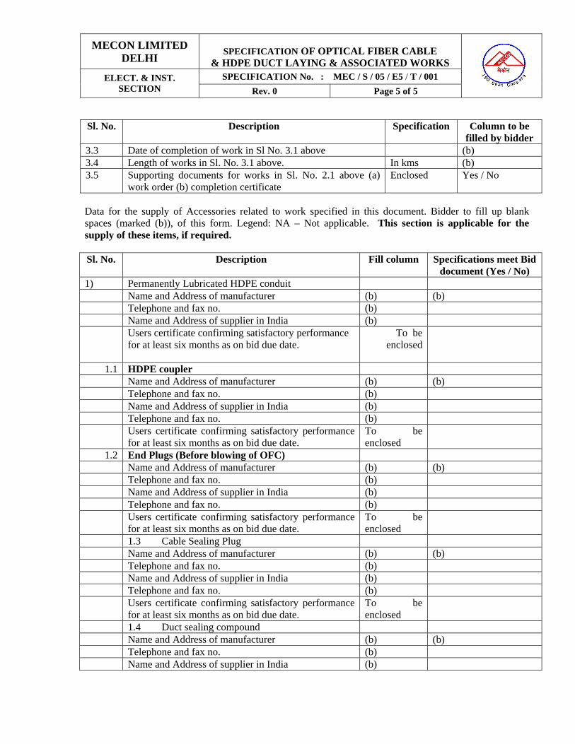
MECON LIMITED DELHI
SPECIFICATION OF OPTICAL FIBER CABLE
& HDPE DUCT LAYING & ASSOCIATED WORKS
SPECIFICATION No. : MEC / S / 05 / E5 / T / 001 ELECT. & INST. SECTION Rev. 0 Page 5 of 5
Sl. No. Description Specification Column to be
filled by bidder 3.3 Date of completion of work in Sl No. 3.1 above (b) 3.4 Length of works in Sl. No. 3.1 above. In kms (b) 3.5 Supporting documents for works in Sl. No. 2.1 above (a)
work order (b) completion certificate Enclosed Yes / No
Data for the supply of Accessories related to work specified in this document. Bidder to fill up blank spaces (marked (b)), of this form. Legend: NA – Not applicable. This section is applicable for the supply of these items, if required. Sl. No. Description Fill column Specifications meet Bid
document (Yes / No) 1) Permanently Lubricated HDPE conduit Name and Address of manufacturer (b) (b) Telephone and fax no. (b) Name and Address of supplier in India (b)
Users certificate confirming satisfactory performance for at least six months as on bid due date.
To be enclosed
1.1 HDPE coupler Name and Address of manufacturer (b) (b) Telephone and fax no. (b) Name and Address of supplier in India (b) Telephone and fax no. (b) Users certificate confirming satisfactory performance
for at least six months as on bid due date. To be enclosed
1.2 End Plugs (Before blowing of OFC) Name and Address of manufacturer (b) (b) Telephone and fax no. (b) Name and Address of supplier in India (b) Telephone and fax no. (b) Users certificate confirming satisfactory performance
for at least six months as on bid due date. To be enclosed
1.3 Cable Sealing Plug Name and Address of manufacturer (b) (b) Telephone and fax no. (b) Name and Address of supplier in India (b) Telephone and fax no. (b) Users certificate confirming satisfactory performance
for at least six months as on bid due date. To be enclosed
1.4 Duct sealing compound Name and Address of manufacturer (b) (b) Telephone and fax no. (b) Name and Address of supplier in India (b)

MECON LIMITED DELHI
SPECIFICATION OF OPTICAL FIBER CABLE
& HDPE DUCT LAYING & ASSOCIATED WORKS
SPECIFICATION No. : MEC / S / 05 / E5 / T / 001 ELECT. & INST. SECTION Rev. 0 Page 6 of 6
Sl. No. Description Fill column Specifications meet Bid
document (Yes / No) Telephone and fax no. (b) Users certificate confirming satisfactory performance
for at least six months as on bid due date. To be enclosed
The Bidder shall be entirely and exclusively responsible for all works under this bid document. Bidder to fill blank spaces (marked (b)), of this form. Legend : NA – Not applicable. Sl. No
Description Performed by (Provide name)
Place of execution of the activity
1.1 Single source responsibility with Performance guarantee for successful completion of scope of work for this project.
Bidder NA
1.2 HDPE conduit laying, sealing and testing (b) Site 1.3 Optical fiber cable Laying (b) Site 1.4 Optical fiber cable jointing & testing (b) Site 1.5 Documentation Bidder NA Bidder shall specifically indicate the deviation related to technical work if any and give proper justification with documentary evidence for specific deviation.
MECON LIMITED DELHI
SPECIFICATION OF OPTICAL FIBER CABLE
& HDPE DUCT LAYING & ASSOCIATED WORKS
SPECIFICATION No. : MEC / S / 05 / E5 / T / 001 ELECT. & INST. SECTION Rev. 0 Page 7 of 7
SECTION 3 (General Guidelines for Bidder): 3.1 The vendor shall be completely responsible for the successful completion of the job. However, to
ensure a good quality of workmanship, and the offered system, vendor shall prepare and submit the documents for approval by the Owner / Consultant.
3.2 Vendor shall be totally responsible for the completion of project. In the event any modifications in
the specification included in the Bid document are warranted, he shall clearly spell out all such requirements at the time of submission of his offer a deviation list for review and approval of owner and consultant.
Vendor may improve upon specification, in such case vendor shall list out all proposed improvements in Deviation list form along-with his offer for review and approval of owner and consultant.
3.3 If during the course of execution of the work, any discrepancy or inconsistency, error or omission
in any or the provisions of the contact is discovered, the same shall be referred to the Consultant for final decision & instruction. He will direct the manner in which the work is to be carried out. The decision of the Owner/Consultant shall be final and conclusive and the vendor shall carry out the work in accordance therewith.
3.4 The data provided in the bid document shall be used for reference purposes for the Bidder. It shall
be the bidder’s responsibility to verify the data & satisfy him in regard to accuracy & utility of their data.
3.5 Splicing and jointing requirements in addition to above, arising out of any negligence on behalf of
the vendor shall be the responsibility of the vendor. In such case, the vendor shall take necessary rectification action at his on cost including necessary materials.

MECON LIMITED DELHI
SPECIFICATION OF OPTICAL FIBER CABLE
& HDPE DUCT LAYING & ASSOCIATED WORKS
SPECIFICATION No. : MEC / S / 05 / E5 / T / 001 ELECT. & INST. SECTION Rev. 0 Page 8 of 8
SECTION 4 (SUB-SYSTEM SPECIFICATIONS) 4.1 OPTICAL FIBER CABLE (for information only)
The selected vendor, before execution of the job may collect the final Optical Fiber cable specification. GENERAL: Corrugated steel tape armored cable or Galvanized steel wire armored optical cable shall be required and it has to cross various roads, railways, canals, small rivers, marshy areas etc. through appropriate casings & directly as per site conditions. The intent of the following specifications is to establish the minimum requirements and guidelines for the Optical fiber cable to be used for this project. Wherever in this section “bidder to specify/bidder to provide” is mentioned, same information can be collected after the award of the contract.
4.1.1 TECHNICAL SPECIFICATIONS OF FIBERS 4.1.1.1 General
The fiber shall fulfil latest ITU-T Recommendation G-652 & G-655 for single mode optical fibers.
a) Total number of fibers Twelve (12) /Twenty four (24) b) Type G.6.25 (12) / G.652 Eighteen (18),G.655 Six(6)
4.1.1.2 Geometrical, optical & physical characteristics of optical fibers
a) Mode field diameter Bidder to specify b) Cladding diameter 125 µm + 2% c) Mode field concentricity error Less than 1 µm d) Cladding non-circularity Less than 2% e) Cut-Off wavelength Bidder to specify f) Protective materials/coatings Optical fibers shall be coated with UV cured
double Acrylic Resin. It should not have any reaction with cladding or core material.
g) Nominal Overall thickness 250 µm
The coatings should provide max. Resistance to micro bending & abrasion and ensure mechanical & optical strength. The coatings shall be easily stripped with mechanical tools.
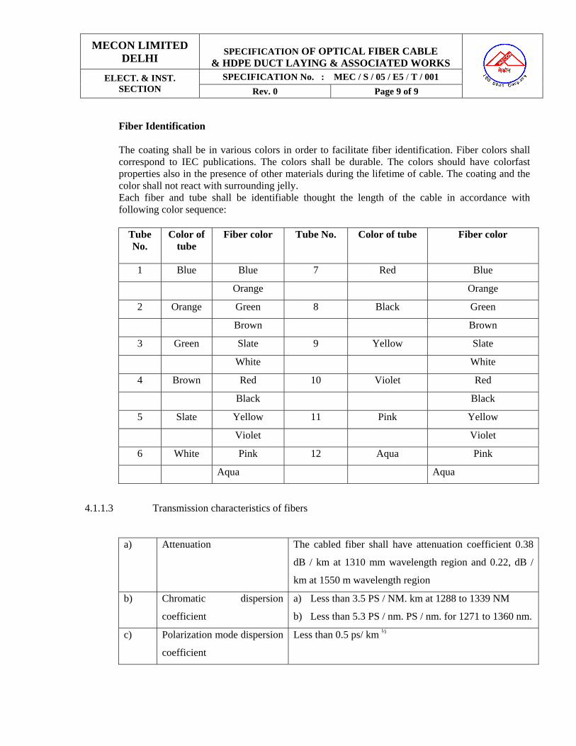
MECON LIMITED DELHI
SPECIFICATION OF OPTICAL FIBER CABLE
& HDPE DUCT LAYING & ASSOCIATED WORKS
SPECIFICATION No. : MEC / S / 05 / E5 / T / 001 ELECT. & INST. SECTION Rev. 0 Page 9 of 9
Fiber Identification The coating shall be in various colors in order to facilitate fiber identification. Fiber colors shall correspond to IEC publications. The colors shall be durable. The colors should have colorfast properties also in the presence of other materials during the lifetime of cable. The coating and the color shall not react with surrounding jelly. Each fiber and tube shall be identifiable thought the length of the cable in accordance with following color sequence:
Tube No.
Color of tube
Fiber color Tube No. Color of tube Fiber color
1 Blue Blue 7 Red Blue
Orange Orange
2 Orange Green 8 Black Green
Brown Brown
3 Green Slate 9 Yellow Slate
White White
4 Brown Red 10 Violet Red
Black Black
5 Slate Yellow 11 Pink Yellow
Violet Violet
6 White Pink 12 Aqua Pink
Aqua Aqua
4.1.1.3 Transmission characteristics of fibers
a) Attenuation The cabled fiber shall have attenuation coefficient 0.38
dB / km at 1310 mm wavelength region and 0.22, dB /
km at 1550 m wavelength region
b) Chromatic dispersion
coefficient
a) Less than 3.5 PS / NM. km at 1288 to 1339 NM
b) Less than 5.3 PS / nm. PS / nm. for 1271 to 1360 nm.
c) Polarization mode dispersion
coefficient
Less than 0.5 ps/ km ½
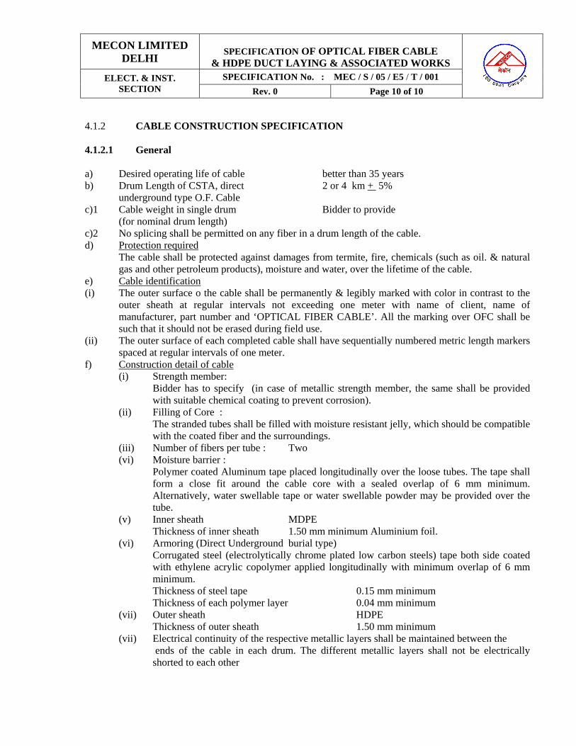
MECON LIMITED DELHI
SPECIFICATION OF OPTICAL FIBER CABLE
& HDPE DUCT LAYING & ASSOCIATED WORKS
SPECIFICATION No. : MEC / S / 05 / E5 / T / 001 ELECT. & INST. SECTION Rev. 0 Page 10 of 10
4.1.2 CABLE CONSTRUCTION SPECIFICATION 4.1.2.1 General a) Desired operating life of cable better than 35 years b) Drum Length of CSTA, direct 2 or 4 km + 5% underground type O.F. Cable c)1 Cable weight in single drum Bidder to provide (for nominal drum length) c)2 No splicing shall be permitted on any fiber in a drum length of the cable. d) Protection required
The cable shall be protected against damages from termite, fire, chemicals (such as oil. & natural gas and other petroleum products), moisture and water, over the lifetime of the cable.
e) Cable identification (i) The outer surface o the cable shall be permanently & legibly marked with color in contrast to the
outer sheath at regular intervals not exceeding one meter with name of client, name of manufacturer, part number and ‘OPTICAL FIBER CABLE’. All the marking over OFC shall be such that it should not be erased during field use.
(ii) The outer surface of each completed cable shall have sequentially numbered metric length markers spaced at regular intervals of one meter.
f) Construction detail of cable (i) Strength member:
Bidder has to specify (in case of metallic strength member, the same shall be provided with suitable chemical coating to prevent corrosion).
(ii) Filling of Core : The stranded tubes shall be filled with moisture resistant jelly, which should be compatible with the coated fiber and the surroundings.
(iii) Number of fibers per tube : Two (vi) Moisture barrier :
Polymer coated Aluminum tape placed longitudinally over the loose tubes. The tape shall form a close fit around the cable core with a sealed overlap of 6 mm minimum. Alternatively, water swellable tape or water swellable powder may be provided over the tube.
(v) Inner sheath MDPE Thickness of inner sheath 1.50 mm minimum Aluminium foil.
(vi) Armoring (Direct Underground burial type) Corrugated steel (electrolytically chrome plated low carbon steels) tape both side coated with ethylene acrylic copolymer applied longitudinally with minimum overlap of 6 mm minimum.
Thickness of steel tape 0.15 mm minimum Thickness of each polymer layer 0.04 mm minimum
(vii) Outer sheath HDPE Thickness of outer sheath 1.50 mm minimum
(vii) Electrical continuity of the respective metallic layers shall be maintained between the ends of the cable in each drum. The different metallic layers shall not be electrically shorted to each other
MECON LIMITED DELHI
SPECIFICATION OF OPTICAL FIBER CABLE
& HDPE DUCT LAYING & ASSOCIATED WORKS
SPECIFICATION No. : MEC / S / 05 / E5 / T / 001 ELECT. & INST. SECTION Rev. 0 Page 11 of 11
4.1.2.2 Mechanical Characteristics of Cable a) Temperature Installation & operation 0° C to + 60° C Storage 0° C to + 65° C b) Tensile strength For CSTA cable 9.81 W Newton (W is weight of 1 km of cable in kg) c) Cable weight in kg/km Bidder to specify d) Minimum bending radius 20 * Cable diameter 4.1.2.3 Average splice loss 0.05 dB / Splice 4.2 JOINTING CLOSURES (for information only)
Jointing closure shall be suitable for armored and unarmored optical fiber cables of all construction designs (slotted core, stranded tube, central tube). Jointing closures shall have 4 entry ports to allow entry/exit of four optical fiber cables. The same shall have provision of blocking/sealing of the ports, if not in use. The fibers and their storage shall be managed with proper bend radius controls and protection. The fiber organizer trays shall have provision of maximum 6 fibers per tray. The trays should be hinged in such a manner that if moved about the hinge, the fibers Are not strained, kinked or stressed. Also, it should be possible to work on the fibers on one tray without disturbing the fibers o the other trays. The jointing closure shall enable the metal parts of the cable and the internal metal parts of the closure to be maintained at earth potential. The sealing of the entry ports, shall provide adequate sealing and shall be capable of withstanding an axial pull applied using 50 kg freely suspended weight of the cable, without using any additional clamps, etc. Jointing closures should be Dust tight (No dust ingress) and protected against immersion in water (suitable for continuous immersion in saline water under 4-meter water-head). It should be complete with all accessories including splice cassettes splice protection and all other accessories including accessories for electrical continuity of metallic layer of optical fiber cable, etc along-with instruction sheets. The jointing closures shall be form one of the following recommended sub-vendors: 1) 3 M, 2) Raychem, 3) Siemens The complete jointing closures including trays, joint protection sleeves etc shall be sourcing form the above sub-vendors as a composite item.

MECON LIMITED DELHI
SPECIFICATION OF OPTICAL FIBER CABLE
& HDPE DUCT LAYING & ASSOCIATED WORKS
SPECIFICATION No. : MEC / S / 05 / E5 / T / 001 ELECT. & INST. SECTION Rev. 0 Page 12 of 12
4.3 SPECIFICATIOS OF PERMANTELY LUBRICATED CONDUIT:
The HDPE conduit shall be permanently lubricated with an inner layer of solid permanent lubricant by co-extrusion method to minimize the internal coefficient of friction. The co-extruded inner layer of above lubricant shall be continuous throughout the length of the HDPE conduit. The HDPE conduits shall also be free of blisters. Shrink hooks, break and other defects. The internal and external pipe surfaces shall be smooth. Pipes shall not display any stress edged grooves or sink marks. The color of the pipes shall be orange and be uniform throughout. The HDPE conduit shall unroll off the drums without snaking or waving having zero coil set. Following are the mechanical and dimensional specifications of HDPE conduit: Pressure Rating : Min. 6 Kg/Cm2
Outer diameter : 4 0 mm. Wall thickness : 4.0 +/- 0.3 mm Tensile strength : 20 N/mm2 or better Density : 940.0 – 950.0 kg/cum at 27° C Melt Flow index : 0.4 to 0.95 gm/10 minutes at 90°
C under 5 Kg load Intrinsic coefficient of friction : 0.06 (max) when tested with respect to Nylon Impact strength : As per IS: 12235 (part 9), 1986 The pipes should confirm to following IS specifications:
1. IS – 7328 4. IS – 2530 2. IS – 9938 5. IS – 4984 3. ASTM D – 1693 HDPE conduit identification : The outer surface of the HDPE conduit shall be permanently & legibly marked with color in contrast to the outer sheath at regular intervals not exceeding one meter with name of client, name of manufacturer and part number. All the markings over HDPE conduit shall be such that it should not be erased during field use. The outer surface of each completed cable shall have sequentially numbered metric length markers spaced at regular intervals of one meter.
5.0 OPTICAL FIBER LAYING PROCEDURE
The cables shall be tested by the bidder himself in the cable drums at the designated stores at site, before installation. The test results pasted on each drum and report to be submitted to site-in-charge. The vendor shall carry out all works concerning the cable laying. The cable shall be laid always on the same side of the pipeline and any crossing of the pipeline shall be avoided. The trench dimensions shall be so taken as to ensure proper laying of the cable including slackness. Vendor

MECON LIMITED DELHI
SPECIFICATION OF OPTICAL FIBER CABLE
& HDPE DUCT LAYING & ASSOCIATED WORKS
SPECIFICATION No. : MEC / S / 05 / E5 / T / 001 ELECT. & INST. SECTION Rev. 0 Page 13 of 13
shall plan the cable-laying schedule such that the complete drum-length of cable can be laid without cutting in-between. The vendor shall prepare the cable drum schedule for this purpose. DIRECT UNDERGROUND BURIAL:
The cable shall be laid in the pipeline trench on the right side of the pipeline in the direction of gas
flow specified by Section in charge. The cable shall be laid in the pipeline trench as shown in Annexure Drawing.
Before laying the cable, 50 mm soft padding of sand or soft soil (riddled earth obtained by passing
through a sieve having meshes not exceeding 15 mm2, or of a natural soft ground not requiring ridding) shall be done as shown in the drawings.
The cable laying (including excavation of trench and installation of cable) shall follow pipeline
lowering. The cable laying, testing and backfilling activities shall preferably be completed before land restoration (e.g. bund preparation, leveling) is started by the pipeline crew.
The cable can be laid using a mobile reel system or a fixed reel system depending on the
characteristics of each section (excavation partially open, crossing etc.) The vendor shall establish section the ways and means for the cable laying taking into account characteristics of the layout.
1) In case of a mobile reel system, the cable shall be laid directly on the prepared bed. Only is special cases, the cable may be laid near the trench and later lowered manually.
The reel support shall be locked in position on the carrier or other means of transportation, as to avoid any rotation on the vertical plane of the reel’s axis.
2) In case of a fixed reel system, the traction stress shall not be more than the permitted
resistance of the cable, prescribed by the cable manufacturer. The pin of the reel shall be put on the proper track. The unwinding shall be supported by hand.
The cable shall be laid near the trench and later lowered in the bed manually, as to avoid damage
to the bed by the operators.
BLOWING / PULLING OF OPTICAL FIBER CABLE
Optical Fiber Cable will be blown into the laid HDPE conduit with the help of a compressor (with minimum pressure of 8 bar and maximum pressure of 12 bar) with flow rate of minimum 10m3/minute) and a blowing machine. The blowing method involves feeding of Optical Fiber Cable into the duct with the help of consistent high-pressure airflow, equally distributed along the entire cable throughout the duct. The Contractor has to ensure the safe blowing of OFC into the duct without any damage to the cable either internally. If at any stage of the project, any damage to the cable due to blowing process is identified, then the Contractor will be fully responsible for that has to ensure the rectification of the damage without any cost implications to the owner. Optical Fiber Cable drum are available in the drum of 2/4 km nominal. There is possible that the Contractor may not able to blow this length continuously. in this case the Contractor should follow steps for safe blowing of OFC as the case may be:

MECON LIMITED DELHI
SPECIFICATION OF OPTICAL FIBER CABLE
& HDPE DUCT LAYING & ASSOCIATED WORKS
SPECIFICATION No. : MEC / S / 05 / E5 / T / 001 ELECT. & INST. SECTION Rev. 0 Page 14 of 14
For Example:-
1. Position the compressor and blowing machine at blowing pit C of 2 Km stretch before A & B as shown below:
Blowing 1 km Blowing 1 Km Blowing Pit A nominal Pit C nominal pit B (Location of comp. & Blowing machine)
2. Uncoil ~ 1 Km of cable in a figure of eight configuration and blow towards blowing pit A and Coil 20 m of OFC in the blowing pit A. Now seal the duct end at location A with the help of cable sealing plug.
3. Coil 20 m of OFC in the blowing pit at location C and seal the duct end with the
help of duct sealing compound.
4. Now uncoil the remaining Optical Fiber Cable from the drum in form of Figure of 8 to have an access to the other end of the cable.
5. Now blow this end of the cable towards the blowing pit B and coil 20 m of OFC
in the blowing pit B. Now seal the duct end at location B with the help of cable sealing plug.
NOTE: Since the cable will be available in length of 2 or 4 KM +/- 5%, the cable length will accordingly vary. So, the Contractor has to plan the location of blowing pits before laying of HDPE conduit. The Contractor has to ensure that excess OFC is not coiled in the blowing pit and also Optical Fiber cable does not fall short of the location of blowing pit. The Contractor has to ensure the safe blowing of OFC for the complete stretch as shown in above figure. To achieve the blowing of above shown stretch, blowing should be carried out downhill wherever possible. The contractor has to do the preliminary survey for proper location of the blowing equipment so that the blowing lengths are not reduced.
CABLE BLOWING PIT /CABLE PULLING PIT
The cable-blowing pit shall enclose HDPE section ends from both sides at every 1-km nominal distance or as per direction of Engineer-in-charge. The cable-blowing pit shall be circular (Internal diameter ~ 1200 mm) and made of reinforced concrete with lifting lungs cast into the lids during contraction itself. The pit shall be provided with suitable arrangement for the entry of HDPE pipes (50/40 mm outer dia ) from both side so that HDPE pipe should enter the pit at a height of 300 mm above the bottom level of the pit and to prevent entry of mud, insects etc.
MECON LIMITED DELHI
SPECIFICATION OF OPTICAL FIBER CABLE
& HDPE DUCT LAYING & ASSOCIATED WORKS
SPECIFICATION No. : MEC / S / 05 / E5 / T / 001 ELECT. & INST. SECTION Rev. 0 Page 15 of 15
CABLE JOINTING PIT
The cable blowing pit as described above will be used as Optical fiber Cable jointing pit every 2 or 4 km nominal distance because the OFC drum length is of 2/4 kM , so at every 2/4 kM nominal distance this pit will be used to enclosed the OFC jointing enclosed of OFC jointing enclosure. Contractor has to leave 20m coil of Optical Fiber Cable from both sides in to leave 20 m coil of Optical Fiber Cable from both sides in the jointing pit i.e. total 40 m of OFC will be coiled in jointing pit. Similarly the Contractor has to leave total 20 m of OFC in the blowing pit
SEALING OF HDPE CONDUIT AFTER BLOWING OF OFC
HDPE conduit will be selected with the help of cable sealing plugs after blowing of Optical Fiber into the duct at jointing pit locations. HDPE conduits will be sealed with the help of Cable Duct Sealing Compound after blowing of Optical Fiber cable into the duct at blowing pit locations.
Cable duct Sealing Compound should be no-toxic, vapor free and should not crack and fail due to vibrations in the duct to temperature changes. Not other sealing material is to be used by the Contractor to seal the ends of HDPE conduit with blown Optical Fiber cable at blowing pit location.
The blowing/ jointing pit will completely filled with sand upto 30 cm from bottom level if the pit
prevent entry of rodents after blowing and jointing of OFC covering joint enclosure and HDPE conduits completely.
5.1 CROSSING (Road, Railways, Nullah, Canal, Minar/ Major River Crossings Cased, Uncased, Marshy area or paddy fields.)
5.1.1 Cased Crossing
For pipeline crossing executed through using pipes or by boring/ jacking/HDD/Thrust Boring methods (Refer Annexure Drawing)
In case of crossing to be done with boring/ jacking/ HDD/ Thrust Boring the OFC shall be laid in HDPE conduit shall be Sub-contractor-ducted in a steel conduit. Easy-to-install cable sealing plug shall be used to seal the ends of the conduit to prevent the ingress of water, dirt and rodents, which may damage of OF Cable. The two ends of each conduit shall be sealed immediately after installation of Sub-contractor-ducts and re-sealed when the cable has been installed inside the conduit.
At bends and leading-in-points, a flexible PVC pipe may be used for protection and maintenance
of the required bending radius of minimum 20 time outer diameter of the cable.

MECON LIMITED DELHI
SPECIFICATION OF OPTICAL FIBER CABLE
& HDPE DUCT LAYING & ASSOCIATED WORKS
SPECIFICATION No. : MEC / S / 05 / E5 / T / 001 ELECT. & INST. SECTION Rev. 0 Page 16 of 16
5.1.2 Uncased Crossings:
For pipeline crossing executed through open cut: For these crossing bidder shall lay the cable through the HDPE conduit. Length of HDPE pipe shall be estimated with the help of survey documents & alignment sheets. For water crossings, HDPE conduit shall be used till ~5m of the normal underground trench depth on either side. The bank protection measure being provided for line pipe shall also be extended to take care of Optical Fiber Cable. For road crossings, the HDPE conduits shall be extended for minimum 3 meters on either side of the road. If casing is provided in open cut crossings then the OFC laying methodology shall be similar to as explain above.
5.2 Terminal and Repeaters
Inside the boundary walls of the terminals and repeaters, the Optical Fiber Cable (s) from each direction shall come to a common point & then shall be laid through HDPE conduit preferably along the wall of the station upto and inside the telecom room. The same shall be similar to Annexure Drawing but with cables/ conduit from both sides. The HDPE pipe used for the leading-in of the Optical Fiber Cable into the telecom room shall be below the ground level without getting exposed outside (which shall be properly sealed after cable installation to avoid entry if rodents, insects, etc.). A 15m length of Optical Fiber Cable shall be kept in the telecom room to facilities termination.
3.3 Tie-in Location At all tie-in location the Optical Fiber Cable shall be laid in a separate trench 3 meter away from
the pipeline to avoid any damage to the Optical Fiber Cable. It shall be as per annexure drawing. The Optical Fiber Cable trench shall extend to 5 meter on both sides of the tie-in locations. The Optical Fiber Cable shall be suitable routed in the separate trench at all tie-in-location considering minimum bending radius of the Optical Fiber Cable. At all these location, the cable shall be laid through HDPE conduits for protection.
5.4 Joint Location The trench shall be enlarged at the splicing points as needed to carry out the splicing works. The
enlargement shall be carried out on the same side of the conduits for protection.
5.5 FIBER TERMINATION CLOSURE (FTC) 5.5.1 TERMINATION
After entering the telecom room the cable shall be secured on `Steel Mesh’ or `Wire Mesh’ by the help ties (-15 cable being kept in turns in oval from) this mesh shall have suitable chemical

MECON LIMITED DELHI
SPECIFICATION OF OPTICAL FIBER CABLE
& HDPE DUCT LAYING & ASSOCIATED WORKS
SPECIFICATION No. : MEC / S / 05 / E5 / T / 001 ELECT. & INST. SECTION Rev. 0 Page 17 of 17
coating/ painted to prevent corrosion. In case of painting, the color shall march the wall color. Further, the cable shall be terminated of Fiber Termination Closure (FTC).
5.5.2 SPECIFICATIONS FOR FIBER TERMINATION CLOSURE
The FTC shall be wall-mounted type as suitable for the Optical Fiber Cable used for this project: (24 Fibers). The FTC shall give grounding arrangement for all the metallic layers of the cable. The cable shall be specified to pigtails on trays provided in the FTC. The connector side for the pigtails shall be secured with suitable coupler/ through adapter provided as integral part of the FTC itself. The FTC shall have trays suitable splicing maximum of 6 Fibers per tray. The arrangement inside the FTC should be simple and in straight line. FTC should have entry points for a minimum of 2 No. of Optical Cable (armored/ non-armored) of diameter up to 20 mm with cable clamps to avoid entry of rodents/ dust in general. It should have a minimum of 2 Nos. of outlets for taking out 24 Nos. Pigtail. The outlets should have cable clamps. The FTC shall be from one of the following makes:
1) 3 M 2) Raychem 3) Krone. The complete Fibre Termination Closure including trays, joint protection sleeves, pigtails, coupler etc. shall be sourced from the above sub-venders as a composite items.
5.5.3 GROUNDING
Grounding arrangement should be provided with the FTC. It should include as minimum 2 Nos. grounding shield bonds with nut and bolts for fixing to the armor of the OFC. 2 Nos. of grounding cable of green color with suitable length & lugs clamped to its end for connecting the armor of OFC with the grounding terminal of the FTC.
5.5.4 SINGLE MODE OPTICAL FIBER PIGTAIL & CONNECTORS TO BE USED IN THE FTC
The single mode fiber pigtails and connectors should meet the TU-T recommendations G-652 & G-655 as required. Both connectors and cable should be robust and should withstand wear and tear due to frequent use, Connection and disconnection. Normal expected life should be 15 year or more. Optical Fiber Cable, connections & pigtails shall be fully compatible and matching to each other.
6.0 LAYING OF PERMANENTLY LUBRICATED HDPE CONDUIT:
Permanently bid lubricated HDPE conduits shall be laid for installation of Optical Fibre Cable. The conduits shall be continuous in length of 1 km. The HDPE laying will follow lowering of pipeline. HDPE conduit should be laid in the pipeline trench bed along with OFC as per Dwg./Sketch enclosed. The duct shall be placed over 50 mm soft padding of sand or soft soil

MECON LIMITED DELHI
SPECIFICATION OF OPTICAL FIBER CABLE
& HDPE DUCT LAYING & ASSOCIATED WORKS
SPECIFICATION No. : MEC / S / 05 / E5 / T / 001 ELECT. & INST. SECTION Rev. 0 Page 18 of 18
(riddled earth obtained by passing through a sieve having meshes not exceeding 15mm2, or of a natural soft ground no requiring riddling) as shown in the drawing. Contractor has to ensure the laying of HDPE conduit without any snaking or waving and the HDPE conduit should rest on the trench bed i.e. the pipe should not hang n the trench bed. The trench will be back filled after ensuring the correct positioning of HDPE conduit as mentioned above. While back filling, the contractor has to ensure that the HDPE conduit is not hanging in the trench bed. Following procedure should be followed for laying HDPE conduits: (A) Moving Trailer Method:
This method should be used when the path of duct does not contain any road/railway bores or utility crossings. Following steps should be followed: 1. Fix the Jack Stand on the trailer properly. 2. Mount the duct coil reel/duct drum on the Jack stand. 3. Bring the trailer at the start point from where the duct is to be laid. 4. Move the trailer slowly along the trench route and uncoil the duct from the bottom
of the reel/drum and place into the trench. Avoid any over spinning of the duct while uncoiling it from the drum.
(B) Manual Laying:
This method is used when there is an obstruction along the route. Following steps should be followed: 1. Place the Jack stand along the side of the trench. Place the drum on the jack with
correct positioning of the drum i.e. the duct reel should uncoil from the bottom of the drum. Duct reel should not uncoil form the top of the drum.
2. Rotate the drum slowly so that the duct comes off the drum slowly and the duct reel should not overseen while pulling HDPE conduit for installation.
3. Unroll the duct to the required length spacing the workers after every 15 to 20 mtrs.
4. If any obstruction like utility crossings or road/railway crossings comes in then ensure the HDPE conduit is drawn under the obstruction or through the crossing without requiring joint in between.
5. The contractor can lay the duct into the trench either directly form the drum or temporally lay the duct along the trench and then place it later in the trench.
C) Tensioning of the HDPE duct after laying :
1. Determine the direction of installation and set the reel. Duct should be unrolled from the bottom of the coil.
2. Place the duct inside the trench.

MECON LIMITED DELHI
SPECIFICATION OF OPTICAL FIBER CABLE
& HDPE DUCT LAYING & ASSOCIATED WORKS
SPECIFICATION No. : MEC / S / 05 / E5 / T / 001 ELECT. & INST. SECTION Rev. 0 Page 19 of 19
3. Let two workers stand on the duct at start point and two other worker stretches the duct, thereby giving tension, upto of 30-40 meters.
4. After covering the 30-40 meter backfill the trench at that point to hold the duct in position and to avoid loss of tension.
5. Repeat the above procedure till the entire duct length of 1 KM laid with proper tensioning.
6. Backfill the entire trenches. To lay the next HDPE duct drum length, couple the laid HDPE ducts to the new drum to be laid with the help of a coupler with same procedure explains above.
6.1 JOINTING OF HDPE CONDUITS:
In case of crossings there may be the possibility that laid HDPE section length may have to be joined to other laid HDPE section length. The jointing of two ends of HDPE conduit should strictly be done with the help of Coupler, which will be made of similar material. Installation of HDPE coupler to join laid HDPE conduits should strictly bee done with the help of C-spanners for proper tightening of Coupler. Joints may also likely to come up due to road/ river/ nallah/ railways crossing. All efforts shall be made to minimize joints. The coupling should be water and airtight and should be able to withstand minimum pressure of 10 bar. Following procedure should be followed for jointing HDPE conduits:
1. Cut the two ducts that are to be jointed at the same place where they overlap.
Cutting should be done in such a way that the duct ends match with the coupler perfectly because is very important that coupling joints be airtight. Proper pipe shears or cutter must be used for smooth cutting Hacksaw should not be used to cut the duct.
2. Debar both the inside and the outside edges of the duct with a debarring tool. 3. Apply a small amount of proper lubricant for better installation of plastic coupler. 4. Tighten the plastic coupler with C-Spanner.
6.2 SEALING OF HDPE CONDUIT:
The Contractor shall supply and put end plugs to seal the end of HDPE ducts after laying of same to prevent ingress of sit, dust etc. Prior to back filling. The end plug should be made of similar material as that HDPE conduit does not change its position due to heavy impact of soils or due to any other cause.
6.3 HDPE CONDUIT TESTING AFTER LAYING: HDPE conduits will be tested for proper laying, crush deformity and pressure testing. The Contractor shall be fully responsible for any obstruction and deformity in the laid HDPE conduit and shall have to remove the obstruction/ deformity of any kind before blowing Optical Fiber Cable into the duct. Following tests are to be carried out on the laid HDPE.

MECON LIMITED DELHI
SPECIFICATION OF OPTICAL FIBER CABLE
& HDPE DUCT LAYING & ASSOCIATED WORKS
SPECIFICATION No. : MEC / S / 05 / E5 / T / 001 ELECT. & INST. SECTION Rev. 0 Page 20 of 20
1) Duct Cleaning: Following steps are to be followed for cleaning the laid HDPE conduit: ♦ Compressed air should be blown through the duct in order to remove any dirt
and water that has accumulated inside the duct with the help of air compressor. A short blast of air of about 1 bar shall be blown through the duct for about 1 minute.
♦ Duct sponges will be blown through the duct to further remove any dirt and water from the duct segment. Sponges should be blown into the duct clean and a dry sponge comes out of the duct.
2) Duct Calibration and integrity Test:
♦ This test is to be done to check the roundness and the integrity of the duct. During installation or backfill process there is possibility of flattening, twisting or
kinking of the duct. This testing process shall be conducted by blowing a plug or probe through the duct segment with compressed air.
♦ Calibration shall be done by a simple sender like small probe,which shall be blown through the duct by compressed air. This probe shall be detectable using a HF Detector.
♦ The calibration process shall be considered completed once the probe exits the duct at the other end after an uninterrupted pass.
♦ When obstruction in the duct are found, these obstruction have to be removed by removing the damaged or deformed portion of the duct and placing a new section of duct.
3) Air Pressure Test :
♦ A static pressure test is to be carried out in order to verify air tightness for the
purpose of cable blowing as well as to prevent ingress of water or dirt during the lifetime of the duct.
♦ To verify the air tightness, pressure inside the duct should be brought up to 10 bar for two minutes. A pressure drop of 0 to 0.5 bar per minute of the test is acceptable. If a higher-pressure drop is detected, no further test should be conducted until the leak has been located and repaired.
♦ After pressure teasing duct ends should be sealed with the help of duct plugs to prevent entering of any dirt and water inside it.
After testing the duct any obstruction both the ends of HDPE conduit shall be plugged
again using end plugs.
MECON LIMITED DELHI
SPECIFICATION OF OPTICAL FIBER CABLE
& HDPE DUCT LAYING & ASSOCIATED WORKS
SPECIFICATION No. : MEC / S / 05 / E5 / T / 001 ELECT. & INST. SECTION Rev. 0 Page 21 of 21
BACK-FILLING
250 mm padding of sand / soft soil shall be done covering the HDPE conduit and then a warning mat (PVC sheet, red color, warning in white, 150mm * 0.1mm in the Bidders scope) shall be placed. After proper padding of the warning mat for min 100mm, the trench shall be backfilled.
WARNING MAT
Bidder shall supply the warning mat as per the MECON Specification No. MEC/TS/05/62/042, Rev-0 and provide Warning mat before back filling. It is Bidder / vendor’s responsibility to collect the information to be printed on the Warning mat before manufacturing. Vendor has to submit Sample print and the all test certificates as per specification to Owner /consultant for review before final dispatch at site. The supplier of the Mat shall have good reputation and past experience for similar job. CABLE MARKERS
The Bidder shall make a 300mm diameter metal plate on the pipeline markers itself (at approx. every kilometer and at crossings). The Bidder shall suitably paint on these metal plates the following:
1. Optical fiber cable. 2. Cable progressive distance w.r.t. the repeater station. This repeater station shall be the
one nearest to the progressive distance in the direction as specified by SIC. 3. Optical fiber cable length 4. Fiber Length. A typical diagram of a joint marker is shown at Annexure, drawing. Cable markers shall be similar to the diagram except the description of joint number.
RECONCILIATION
For accounting of optical fiber cable, all cut pieces measuring in length of 100 meter and above when returned to Owner’s storage points, shall be treated as serviceable materials. All cut pieces of cables measuring less than 100 meter will be treated as scarp.
For accounting of optical fiber cable following allowances shall be permitted:
a) The basic length of optical fiber cable will be the length of pipeline as per pipeline
chainage and not cable length.
b) To take care of the terrain undulations and optical fiber cable slackness in trench and any unaccountable wastage including scrap etc., an allowance of 2% of pipeline length will be considered.

MECON LIMITED DELHI
SPECIFICATION OF OPTICAL FIBER CABLE
& HDPE DUCT LAYING & ASSOCIATED WORKS
SPECIFICATION No. : MEC / S / 05 / E5 / T / 001 ELECT. & INST. SECTION Rev. 0 Page 22 of 22
c) (1) At each planned jointing location, 40m of additional optical fiber cable length shall be considered. The same will not be considered for unplanned joints arising out of vendor negligence (not owner’s requirement).
(2) At blowing pits (other than planned joint location) 20m of additional Optical Fibre
Cable shall be considered.
d) At each repeater locations the following will be considered:
(1) From pipeline limit upto telecom building entry point in separate trench Actual length.
(2) Telecom building entry point into the telecom room-Actual length.
e) At manned locations the following will be considered:
(1) From station limit upto telecom building entry point in separate trench Actual length.
(2) Telecom building entry point into the telecom room-Actual length.
f) Serviceable materials (all cut pieces of cable Measuring 100 meter and above) subject to
the following : </=0.25% of total cable length
1) Acceptable physical conditions i.e. no kinks, no exposure of armor. 2) Successful OTDR testing 3) Both ends being sealed using heat shrinkable end caps.
For unaccounted optical fiber cable not returned to owner after reconciliation, deductions of 1.25 times the landed cost of optical fiber cable will be made.
JOINTING
Each splice loss shall be < 0.1 dB at 1310 nm. In all the jointing locations (normal joints at the end of each drum as well as other joints) at least 20m of cable from each end of the cable shall be left surplus in a coiled. During jointing, electrical continuity of each of the metallic layer in the optical fiber cable shall be maintained. After completion of each joint at site, it shall be tested for water proof-ness by immersing it is water along-with OFC for 5 minutes. Jointing closures shall be issued to the vendor as a free issue material for all planner joints as per the approved cable alignment sheets. (Cable alignment sheets are to be submitted immediately after award of work for approval of owner/consultant). Jointing closures, jointing pits and all

MECON LIMITED DELHI
SPECIFICATION OF OPTICAL FIBER CABLE
& HDPE DUCT LAYING & ASSOCIATED WORKS
SPECIFICATION No. : MEC / S / 05 / E5 / T / 001 ELECT. & INST. SECTION Rev. 0 Page 23 of 23
accessories (along–with jointing, installation of joints, jointing pits etc. all complete) for unplanned joints shall be provided by the vender at their own cost. The OFC coil shall rest on the floor of the pit after turns being secured with cable ties. The lid of the jointing pit should be ~1000mm below the ground level after installation. The HDPE conduit shall enter the pit at the bottom level of the pit. Proper arrangement should be done for protection of the cable at the entry points (Sealing of the HDPE conduit entry points at the jointing / blowing pits e.g. sealing of the cable entry points after cable installation).
Joint markers
All jointing locations shall be marked with proper identification markers. The Bidder shall supply fabricate and install the joint location markers. These markers shall be in line to the markers as given in Annexure Drawing/Sketch of this Bid document. The markers shall show the progressive joint No. and distance of the Joint as directed by site- Incharge. (SIC) These markers shall be installed approximately 1mtr away from the jointing pit in the direction as per the instruction of SIC/Owner.
Electronic markers
Additionally, bidder shall provide electronic locating system suitable for field use to locate underground-buried Optical fiber cable joints. The system shall consist of:
a) Electronic marker (to be buried underground along-with Optical fiber cable joints).
b) Marker locator (including probe & locator electronics). c) The electronic markers shall be placed at all joint locations (planned and
unplanned). The electronic markers shall be lightweight and shall have a passive tuned resonant circuit, enclosed and sealed within a casing. The marker locator shall be able to locate the electronic markers from a distance of 2.2m minimum with the help of audio and visual signals. The markers shall be of color suitable for Oil & Gas application. The marker locator and the probe shall be of lightweight and portable enough to be carried (in suitable carrying case, to be provided) on shoulder. The locator shall be able to work on batteries (dry alkaline) for continuously 8 hours. The electronic locating system shall be able to work in saline atmosphere in coastal area and shall be protected against corrosion. The electronic locating system shall not be affected by any metal, alternating current, etc. The casing of the electronic marker shall be resistant to chemicals, minerals, water ingress and
MECON LIMITED DELHI
SPECIFICATION OF OPTICAL FIBER CABLE
& HDPE DUCT LAYING & ASSOCIATED WORKS
SPECIFICATION No. : MEC / S / 05 / E5 / T / 001 ELECT. & INST. SECTION Rev. 0 Page 24 of 24
temperature variation normally encountered in underground environments. The material used for the manufacture of electronic markers shall be protected against any damage due to rodents or any other insects in the underground environment. Each marker locator provided shall be complete with its set of accessories (i.e. necessary interfaces, connecting cables, software, etc.)
The electronic markers shall be buried underground 30 mm above the lid of the jointing pits and shall not be in direct contract with any metallic body.
MECON LIMITED DELHI
SPECIFICATION OF OPTICAL FIBER CABLE
& HDPE DUCT LAYING & ASSOCIATED WORKS
SPECIFICATION No. : MEC / S / 05 / E5 / T / 001 ELECT. & INST. SECTION Rev. 0 Page 25 of 25
SECTION 5 (GENERAL) 5.1 VENDOR DATA REQUIREMENT AND DOCUMENTATION
(Exclusively for OFC Telecom work) a) Six sets of Documentation shall be supplied with each submission. b) All documents shall be in English language only. c) During engineering stage, owner/consultant shall review/approve
drawings/documents to be mutually agreed with the vendor.
5.1.1 With each initial bid, the following documents shall be submitted (for information only) :
CV’s of key personnel has to be associated in this project.
5.1.2 After the award of work, the Bidder for review and approval from Owner/Consultant shall supply the following documents in order to start cable laying at site:
1) Supply of cable alignment sheet.
Cable alignment shall comprise the following as a minimum. i) Detailed measurement of length of optical fiber cable route along-with details of
road, nullah, river crossings, high Tension lines etc.
ii) Location of Terminals, repeaters and planned joints.
For the sections where the cable route may leave the pipeline route, the vendor shall make a proper topographic survey to define the route and to determine the existence of over ground or underground services that could interfere with the installation. The vendor shall thereafter prepare a cable route sheet with proper scale showing the entire crossing and topographic details as needed to define the route and its characteristics.
2) Procedure for laying Optical Fibre cable through Permanently Lubricated HDPE conduit
across any river / bridge.
3) Procedure for laying Optical Fibre cable through Permanently Lubricated HDPE conduit across Minor River, nullah and road crossing.
4) Optical fiber cable jointing procedure.
5) Quality Assurance program as requested and the following: a) Daily optical fiber laying/ jointing/ testing report formats. b) Approved documents for all the material to be used during optical fiber laying i.e.
HDPE, warning mat etc.
MECON LIMITED DELHI
SPECIFICATION OF OPTICAL FIBER CABLE
& HDPE DUCT LAYING & ASSOCIATED WORKS
SPECIFICATION No. : MEC / S / 05 / E5 / T / 001 ELECT. & INST. SECTION Rev. 0 Page 26 of 26
6) Factory acceptance test procedure for HDPE conduit shall be provided.
7) Any other data, document not specifically mentioned, but required for the satisfactory
completion, operation and maintenance of the system shall be provided.
5.1.3 Documents to be supplied before ‘Final acceptance certificate’ issued by Owner: 1) As built cable route sheets shall comprise the following as a minimum :
i) Location of joints, crossings. ii) At each joint location.
a) Progressive optical fiber cable length, including the additional
length at each joint location. b) Fiber length, fiber length between joints, as measured by OTDR. c) Progressive pipeline chainage. d) Distance of joint from nearest pipeline markers & crossings, etc.
2) Final cable test reports (individual cable drums, hop to hop between repeaters,
section and end to end). 3) All final documents for this project in electronic form.
5.2 VENDOR’S SITE OFFICE
Vendor’s site office shall be capable of performing the following function :
a) Receipt of cable drums / equipment/goods at site, checking them for correctness and
completeness, storage, transportation of good, etc. b) Installation of the optical fiber cable in best engineering practice and workmanship. c) Check out on proper installation. d) Liaison with Vendor’s head office. e) Jointing, Testing and commissioning activities. f) Conducting site acceptance testing to the satisfaction of owner.
5.3 QUALITY ASSURANCE PROGRAM:
a) Bidder shall submit the details of Quality Assurance Program followed by him. Bidder shall obtain and forward the Quality Assurance Program for material supplied by the Sub-Vender.
b) The Owner /Consultant reserves the right to inspect and test each material / equipment at all stages of production and commissioning of the system. The inspection and the testing shall include but not limited to raw materials, components, sub- assemblies, prototypes, final product etc.

MECON LIMITED DELHI
SPECIFICATION OF OPTICAL FIBER CABLE
& HDPE DUCT LAYING & ASSOCIATED WORKS
SPECIFICATION No. : MEC / S / 05 / E5 / T / 001 ELECT. & INST. SECTION Rev. 0 Page 27 of 27
c) For factory inspection and testing, Bidder shall arrange all that is required e.g. QA personnel, space, test equipments etc. for successful carried out of the jab by Owner / consultant at Bidder’s cost at manufacturer’s works. This excluded the costs of transportation, lodgings, boarding of the Owner / consultant.
d) It shall be explicitly understood that under no circumstances shall any approval of the Owner / consultant relieve the Bidder of his responsibility for material, design, quality assurance and the guaranteed performance of the system and its constituents.
e) Bidder shall invite the Owner / consultant, at least 15 days in advance, of the date at which system shall be ready for Inspection and testing. All relevant documents and manuals, approved engineering drawing etc. shall be available with Owner / consultant well in advance of the start of inspection and testing.
f) Owner / consultant or his representative shall after completion of inspection and testing to their satisfactions, issue factory acceptance certificate to release the equipments for shipment. No equipments shall be shipped under any circumstances unless a factory acceptance certificates has been issued for it, unless agreed otherwise by the owner / consultant.
5.4 TESTING & FINAL DOCUMENTATION
The following tests (in the same sequence) shall be conducted final acceptance of material / laid cable.
A1 Factory acceptance testing (if applicable)
A2 Regular Testing
A3 Site Acceptance Testing (SAT)
a) These tests shall be carried out on all material Equipment supplied by bidder including
those supplied by sub vendors, if any b) Bidder shall arrange all necessary test instruments, manpower, testing gear, accessories etc
c) All technical personal assigned by bidder shall be fully conversant with the system
specification and requirements They shall have the specific capability to make the system operative quickly and efficiently and shall not interfere or be interfered by other concurrent testing, construction and commissioning activities in progress. They shall also have the capability to incorporate any minor modification / suggestion put forward by owner / consultant.
d) Power supply and any temporary commissioning facility including communication system
required for installation / testing / commissioning of the material / cable laying etc. shall be arranged by the bidder.
MECON LIMITED DELHI
SPECIFICATION OF OPTICAL FIBER CABLE
& HDPE DUCT LAYING & ASSOCIATED WORKS
SPECIFICATION No. : MEC / S / 05 / E5 / T / 001 ELECT. & INST. SECTION Rev. 0 Page 28 of 28
e) TEST PLAN
Bidder shall submit to owner and consultant ‘Test Plans “ well in advance of commencement of actual testing in each of the above mentioned test categories (refer clause a) The plans shall include: i) Test to be conducted and purpose of test. ii) Test procedure (including time schedule for the tests) and identification of test
inputs details and desired test results.
f) Test Report
The observation and test results obtained during various tests conducted shall be compiled and documented to produce test reports by bidder. The test reports shall be given for each hop of the concerned section. The report shall contain the following information to a minimum. 1. Test Results 2. Comparison of test results with anticipated ( as per specifications) test results as
given in test plans and reason for deviation if any . 3. The data furnished shall prove convincingly that :
a) The system meets the guaranteed performance objectives. b) Mechanical and electrical limits were not exceeded.
Factory Acceptance Testing for the Items to be supplied by the Bidder: ( FAT if applicable)
Factory acceptance test shall be carried out after review and approval of FAT procedures/ documents and shall be conducted at the manufacturing facilities from where the respective material / subsystems are offered. The factory acceptance testing shall be conducted in the presence of the owner / consultant. The test shall be carried out on all equipment/ items including those supplied by sub vendors and factory acceptance certificates shall be issued. The factory test shall include but not limited to :
1. Mechanical checks to the equipment for dimensions, inner and outer supports,
finishing, welds, hinges, terminal boards, connectors, cables, painting etc. 2. Check for assuring compliance with standards mentioned in the specifications 3. Individual check on each / module / sub-assembly in accordance with the modes
and diagnostics programs of the bidder. 4. Environmental testing. 5. Functional tests. 6. Any other test not included in FAT document but relevant to the project as desired
by owner / Consultant at the time of Factory acceptance testing.
MECON LIMITED DELHI
SPECIFICATION OF OPTICAL FIBER CABLE
& HDPE DUCT LAYING & ASSOCIATED WORKS
SPECIFICATION No. : MEC / S / 05 / E5 / T / 001 ELECT. & INST. SECTION Rev. 0 Page 29 of 29
Regular Testing:
After laying and jointing of cables and back – filling of the trench, the cable shall be tested for attenuation over the laid cable and log off the same in Daily optical fibber cable laying, jointing, testing format shall be maintained.
SITE ACCEPTANCE TESTING ( SAT ) & FINAL ACCEPTANCE.
Site acceptance testing for handing over of laid cable and HDPE duct shall be done in the presence of owner / consultant / telecom system vendor in the format provided by site in charge. Upon successful completion of the ‘ Site Acceptance Testing ‘ any shortfalls when compared to the contract shall be made good by the vender. The Bidder shall then provide as built documents as specified. After this, Owner / consultant shall notify the vendor in writing his final acceptance of the laid cable/Duct and the cable /Duct shall be considered ‘commissioned’. Bidder shall hand over to all free issued items after reconciliation to Owners store. Nothing herein above provided, inclusive of the ‘Final Acceptance Certificate’ shall absolve vender of his full liabilities under the contract inclusion of and relative to the system performance and material Guarantee/warranty.
********************
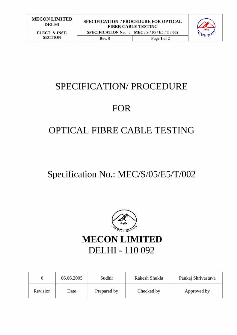
MECON LIMITED DELHI
SPECIFICATION / PROCEDURE FOR OPTICAL
FIBER CABLE TESTING
SPECIFICATION No. : MEC / S / 05 / E5 / T / 002 ELECT. & INST. SECTION Rev. 0 Page 1 of 2
SPECIFICATION/ PROCEDURE
FOR
OPTICAL FIBRE CABLE TESTING
Specification No.: MEC/S/05/E5/T/002
MECON LIMITED DELHI - 110 092
0 06.06.2005 Sudhir Rakesh Shukla Pankaj Shrivastava
Revision Date Prepared by Checked by Approved by

MECON LIMITED DELHI
SPECIFICATION / PROCEDURE FOR OPTICAL
FIBER CABLE TESTING
SPECIFICATION No. : MEC / S / 05 / E5 / T / 002 ELECT. & INST. SECTION Rev. 0 Page 2 of 2
INDEX
1. TEST PROCEDURE 1.1 FIBRE LENGTH MEASUREMENT 1.1.1 Test Description 1.1.2 Test Equipment 1.1.3 Procedure 1.2 INSERTION LOSS MEASUREMENT 1.2.1 Test Description 1.2.2 Tools and Equipment required 1.2.3 Procedure Appendices : Appendix – 1 (A & B) : Test Format : Fibre Length Measurement Appendix – 2 (A & B) : Test Format : Insertion Loss Measurement
MECON LIMITED DELHI
SPECIFICATION / PROCEDURE FOR OPTICAL
FIBER CABLE TESTING
SPECIFICATION No. : MEC / S / 05 / E5 / T / 002 ELECT. & INST. SECTION Rev. 0 Page 1 of 2
TEST PROCEDURE The Optical Fibre cable will be tested for its continuity and average loss in dB/km. The link will be tested and recorded in the format given in Appendix-1 & 2. 1.1 Fibre Length Measurement 1.1.1 Test Description
This test will check the continuity of the fibre from station to station and record the length of fibre. Average loss per kilometer of fibre length shown in dB/km shall be recorded for information only. Testing will be done from both ends and average will be calculated (for both 1310 nm and 1550 nm).
1.1.2 Test Equipment
1. Optical Time Domain Reflectometer (OTDR) 2. Patchcords, pigtails
1.1.3 Procedure
• Power on the OTDR and make the settings as required for the top under test. • Splice a pigtail to one of the fibres • Connect the OTDR with pigtail • Make the laser ON and observe the trace till it gets settled up to the end of the
trace. • Store the results in the hard disk/floppy disk with proper identification of the
fibre under test. • Record the results in format • Repeat the procedure for the Opposite direction. • Test Formats are provided in Appendix-1 (A & B) • Repeat above steps for each fibre
1.2 Insertion Loss Measurement 1.2.1 Test Description
During the insertion loss measurement, light is launched (LASER) in the fibre by using a LASER source from one end at the other end by using an Optical Power meter the received is measured. Fibre loss is calculated by subtracting the receive power from the transmit power. This test also determines the fibre termination continuity on end to end basis as the measurement is done on both the ends of a link.
1.2.2 Tools and Equipment required
1. Power meter working on 1310 nm and 1550 nm 2. Laser source working on 1310 nm and 1550 nm

MECON LIMITED DELHI
SPECIFICATION / PROCEDURE FOR OPTICAL
FIBER CABLE TESTING
SPECIFICATION No. : MEC / S / 05 / E5 / T / 002 ELECT. & INST. SECTION Rev. 0 Page 2 of 2
3. Patchcords (10 mtrs)
1.2.3 Procedure
• One power meter, one laser source and one unit of optical talk set are required at
each end. • At location A, switch ON the laser source, set it to operating wavelength of 1310
nm and connect it to the power meter (set at 1310 nm) by patch cord and record the laser power transmitted. Record it in the test sheet.
• Cut the patch cords, laser source & power meter remaining connected to the 2
halves of the patch cord (i.e. 2 pig tails). • Splice each of the pigtails to two ends of the same fibre under test. • Record the power received in test sheet • To establish communication between two stations A & B, connect the Optical
talk set to one of the fibre (for example fibre No. 24) at both the stations. When that particular fibre is next for testing connects the talk set to one on which testing is complete (for example fibre No.1).
• Confirm on the talk set that the power received is recorded. • Repeats the test for 1550nm. • Connect the source to next connector at Location A and Power Meter at
Location B. • Repeat the same procedure with source at Location B and Power Meter at
Location A. • Continue the above process till all fibres are tested • Average loss of each fibre should be less than the average loss estimated.
• Test formats are provided in Appendix-2 (A & B)

MECON LIMITED DELHI
SPECIFICATION / PROCEDURE FOR OPTICAL
FIBER CABLE TESTING
SPECIFICATION No. : MEC / S / 05 / E5 / T / 002 ELECT. & INST. SECTION Rev. 0 Page 1 of 4
Appendix-1 A FIBRE LENGTH MEASUREMENT
Date : _____________________ Location A : _____________________ Location B : _____________________ Wavelength : 1310 nm Equipment used : _____________________
Tube Fibre Fibre Length Optical loss dB/km No./ color No./ Color (m) From A From B
1. Blue 1. Blue 2. Orange 2. Orange 3. Green 4. Brown 3. Green 5. Slate 6. White 4. Brown 7. Red 8. Black 5. Slate 9. Yellow 10. Violet 6. White 11. Pink 12. Aqua 7. Red 13. Blue 14. Orange 8. Black 15. Green 16. Brown 9. Yellow 17. Slate 18. White 10. Violet 19. Red 20. Black 11. Pink 21. Yellow 22. Violet 12. Aqua 23. Pink 24. Aqua
Cable loss (average of above) : __________________________ km (ALL LOSSES MEASURED IN dB/km) Signature & date Signature & date (Tested & handed over by (Witnessed & Taken over by Cable laying vendor for HDD) Main Line cable laying vendor) Signature & date Witnessed by Client/MECON representative (s)
MECON LIMITED DELHI
SPECIFICATION / PROCEDURE FOR OPTICAL
FIBER CABLE TESTING
SPECIFICATION No. : MEC / S / 05 / E5 / T / 002 ELECT. & INST. SECTION Rev. 0 Page 2 of 4
Appendix-1 B FIBRE LENGTH MEASUREMENT
Date : _____________________ Location A : _____________________ Location B : _____________________ Wavelength : 1550 nm Equipment used : _____________________
Tube Fibre Fibre Length Optical loss dB/km No./ color No./ Color (m) From A From B
1. Blue 1. Blue 2. Orange 2. Orange 3. Green 4. Brown 3. Green 5. Slate 6. White 4. Brown 7. Red 8. Black 5. Slate 9. Yellow 10. Violet 6. White 11. Pink 12. Aqua 7. Red 13. Blue 14. Orange 8. Black 15. Green 16. Brown 9. Yellow 17. Slate 18. White 10. Violet 19. Red 20. Black 11. Pink 21. Yellow 22. Violet 12. Aqua 23. Pink 24. Aqua
Cable loss (average of above) : __________________________ km (ALL LOSSES MEASURED IN dB/km) Signature & date Signature & date (Tested & handed over by (Witnessed & Taken over by Cable laying vendor for HDD) Main Line cable laying vendor) Signature & date Witnessed by Client/MECON representative (s)
MECON LIMITED DELHI
SPECIFICATION / PROCEDURE FOR OPTICAL
FIBER CABLE TESTING
SPECIFICATION No. : MEC / S / 05 / E5 / T / 002 ELECT. & INST. SECTION Rev. 0 Page 3 of 4
Appendix-2 A INSERTION LOSS MEASUREMENT
Date : ___________________ Location A : ___________________Location B : __________________ Wavelength : 1310 nm Equipment used : ___________________ Cable Length from Appendix 1A : _________ km Number of Splices (including Pigtails-N : ________________ Number of connectors-C : ___________________ Average IL = 0.38L + 0.1N + 0.5C : _________ (estimated)
A-B B-A Average Power Transmitted at A Power Transmitted at B
Tube No./ color
Fibre No./ Color
Power received at B
IL (A-B) Power received at A
IL (B-A) IL
1. Blue 1. Blue 2. Orange 2. Orange 3. Green 4. Brown 3. Green 5. Slate 6. White 4. Brown 7. Red 8. Black 5. Slate 9. Yellow 10. Violet 6. White 11. Pink 12. Aqua 7. Red 13. Blue 14. Orange 8. Black 15. Green 16. Brown 9. Yellow 17. Slate 18. White 10. Violet 19. Red 20. Black 11. Pink 21. Yellow 22. Violet 12. Aqua 23. Pink 24. Aqua (ALL LOSSES MEASURED IN dB/km) Signature & date Signature & date (Tested & handed over by (Witnessed & Taken over by Cable laying vendor for HDD) Main Line cable laying vendor) Signature & date Witnessed by Client/MECON representative (s)

MECON LIMITED DELHI
SPECIFICATION / PROCEDURE FOR OPTICAL
FIBER CABLE TESTING
SPECIFICATION No. : MEC / S / 05 / E5 / T / 002 ELECT. & INST. SECTION Rev. 0 Page 4 of 4
Appendix-2 B INSERTION LOSS MEASUREMENT
Date : ___________________ Location A : ___________________Location B : __________________ Wavelength : 1550 nm Equipment used : ___________________ Cable Length from Appendix 1A : _________ km Number of Splices (including Pigtails-N : ________________ Number of connectors-C : ___________________ Average IL = 0.22L + 0.1N + 0.5C : _________ (estimated)
A-B B-A Average Power Transmitted at A Power Transmitted at B
Tube No./ color
Fibre No./ Color
Power received at B
IL (A-B) Power received at A
IL (B-A) IL
1. Blue 1. Blue 2. Orange 2. Orange 3. Green 4. Brown 3. Green 5. Slate 6. White 4. Brown 7. Red 8. Black 5. Slate 9. Yellow 10. Violet 6. White 11. Pink 12. Aqua 7. Red 13. Blue 14. Orange 8. Black 15. Green 16. Brown 9. Yellow 17. Slate 18. White 10. Violet 19. Red 20. Black 11. Pink 21. Yellow 22. Violet 12. Aqua 23. Pink 24. Aqua (ALL LOSSES MEASURED IN dB/km) Signature & date Signature & date (Tested & handed over by (Witnessed & Taken over by Cable laying vendor for HDD) Main Line cable laying vendor) Signature & date Witnessed by Client/MECON representative (s)

MECON LIMITED DELHI
TECHNICAL SPECIFICATION OF
OPTICAL FIBER CABLE & ACCESSORIES
SPECIFICATION No. : MEC / TS / 05 / E5 / T / 096 ELECT. & INST. SECTION
Rev. 1 Page 1 of 1
TECHNICAL SPECIFICATION FOR
OPTICAL FIBRE CABLE &
ASSOCIATED ITEMS
Technical Specification No. : MEC / TS / 05 / E5 / T / 096
MECON LIMITED
DELHI - 110 092
1 28.06.2006 Sachin Agrawal Rakesh Shukla Pankaj Shrivastava
Revision Date Prepared by Checked by Approved by
MECON LIMITED DELHI
TECHNICAL SPECIFICATION OF
OPTICAL FIBER CABLE & ACCESSORIES
SPECIFICATION No. : MEC / TS / 05 / E5 / T / 096 ELECT. & INST. SECTION
Rev. 1 Page 2 of 2
INDEX 1.0 INTRODUCTION 2.0 DATA TO BE FURNISH BY THE BIDDER 3.0 SCOPE OF WORK 4.0 DESIGN OBJECTIVES AND GUIDELINES 4.1 Standards applicable 4.2 Approval of documents 4.3 General Guidelines 5.0 SUB SYSTEM SPECIFICATIONS 5.1 Optical fibre cable 5.2 Jointing Closures with accessories 6.0 GENERAL SPECIFICATIONS 6.1 Vendor data requirements & documentation 6.2 Training 6.3 Packing 6.4 Quality Assurance Programme & Testing Annexure ‘1’ : Cable Construction for 24 count CSTA Optical Fibre Cable Annexure ‘2’ : Unpriced Bill of Materials
MECON LIMITED DELHI
TECHNICAL SPECIFICATION OF
OPTICAL FIBER CABLE & ACCESSORIES
SPECIFICATION No. : MEC / TS / 05 / E5 / T / 096 ELECT. & INST. SECTION
Rev. 1 Page 3 of 3 1.0 INTRODUCTION :
An Optical Fiber (OFC) system for the Telecommunication requirements has been most suitable for gas pipeline project. Laying of OFC along with pipeline are present trend to economized the project cost. It is proposed to procure 24 fibre OFC designated for Blowing through Duct and direct burial application to meet the telecommunications requirements. The OFC shall be blown into the self-lubricated HDPE Duct directly using “Blowing Techniques”.
As part of this project, it is desired to provide necessary OFC and associated items, as per the specifications provided in the Bid documents. This will provide only the Technical requirements for Optical Fibre Cable and Associated items.
2.0 DATA TO BE FURNISHED BY THE BIDDER:
(Bidder shall furnished this information at the time of their offer and it will be part of contract for successful bidder, the information necessarily to be submitted during the Bid submission otherwise their offer may be rejected / disqualified for OFC work)
Sl. No.
Description Specification To be filled by bidder
1 Name & address of the Bidder for OFC. 1.1 Whether Bidder is OFC Manufacturer OFC Yes/ No 1.2 Supply Record 1.2 a Manufacturing facilities from which OFC were
supplied for earlier projects within last three years from the bid date.
- Jelly Filled, 1300nm/ 1550nm, single mode CSTA/ ECCS, slotted core / loose tube OFC, as per ITUG-652 - OFC as per ITUG-655
1.2 b Whether the manufacturing facilities for the cables in 1.2 a above is Bidder’s own facility.
Yes/ No
1.2 c Detail of order in respect of having supplied minimum 155 KMs of OFC in last three years including at least 100 KMs of steel Tap armoured OFC.
1500 KMs (minimum) 100 KMs (minimum)
1.2 d Detail of manufacturing facilities of OFC for the project including locations / capacity etc.
1.2 e Model no. of offered optical fiber cable. 1.2 f Enlist the documentary evidence of Bidder’s capability
to manufacturing and supply of above a) P.O.Copies Order completion certificate
To be enclosed
1.2 g Name of the manufacturer of Optical fibre 2.0 Jointing Closure 2.1 Name and Address of the Bidder / supplier 2.2 Place of manufacturing 2.3 Users certificate confirming satisfactory performance
for at least six months as on bid due date.
2.4 Special tool and Tackles as per the list given in the Bill of quantity
The Bidder shall be entirely and exclusively responsible for all works under this bid document. Bidder to fill blank spaces (marked (b)), of this form. Legend : NA – Not applicable.

MECON LIMITED DELHI
TECHNICAL SPECIFICATION OF
OPTICAL FIBER CABLE & ACCESSORIES
SPECIFICATION No. : MEC / TS / 05 / E5 / T / 096 ELECT. & INST. SECTION
Rev. 1 Page 4 of 4 Sl. No
Description Performed by (Provide name)
Place of execution of the activity
1.1 Single source responsibility with Performance guarantee for successful completion of scope of work for this project.
1.2 Design & Engineering 1.3 Optical fiber cable & accessories 1.4 Documentation
Bidder shall specifically indicate the deviation related to technical work if any and give proper justification with documentary evidence for specific deviation.
3.0 SCOPE OF WORK : 3.1 SCOPE OF WORK 3.1.1 The Scope of work shall include supply of optical fibre cable, joint closure and tools
as per the specification / requirement given in this document
The fibre for the cable can be procured from any reputed fibre manufacturer and the inspection of the offered fibre shall be carried out at the premises of fibre manufacturer or cable manufacturer at Owner’s prerogative.
Compliance with the requirements of this specification does not relieve the Supplier of the equipment of proper design, meeting all the specified rated operating and service conditions The fibre for the cable can be procured from any reputed Optical Fibre manufacturers but preferably from one of the followings:
1. Lucent 2. Fujikura 3. Corning 4. Alcatel 5. Sumitomo 6. Furukawa 7. Sterlite
Optical fibre shall meet all the technical specification mentioned in the tender documents. All technical documents regarding procurement of optical fibre is to be supplied to Owner / MECON. Owner / MECON reserves the right to check the technical specifications of the fibre prior to fabrication/ manufacturing of cable. Supplier has to offer the fibre for inspection either in the premises of fibre manufactures/ cable manufactures or wherever testing facility exists. However, Owner / MECON reserves the rights to get the optical fibre tested for its technical parameters from any recognized independent test houses in India and abroad.
3.1.1.1 Design, Engineering, Manufacture, Testing and supply of Corrugated steel tape armoured (CSTA) or Electrolytically Chrome Plated Low Carbon Steel Armoured (ECCSA) optical fibre cables as follows:
- Multi-grade cable of 24 fibre counts, out of this 6 fibre counts are ITU-T G.655 and 18 fibre counts are ITU-T G.652 specification embedded in one cable suitable for direct underground burial application.
MECON LIMITED DELHI
TECHNICAL SPECIFICATION OF
OPTICAL FIBER CABLE & ACCESSORIES
SPECIFICATION No. : MEC / TS / 05 / E5 / T / 096 ELECT. & INST. SECTION
Rev. 1 Page 5 of 5
However OF cable shall be laid in a permanently lubricated HDPE pipe using blowing techniques.
3.1.1.2 Manufacture/Procurement, Testing and supply of suitable Joint closures including all necessary accessories of any of the following make:
i) Raychem ii) 3M iii) Siemens
3.1.1.3 Supply of Special Tools and Tackles as mentioned in the Bill of quantity. The Tools &
Tackles to be supply for the joints closures should be from the same manufacturing as that of the joint closures.
3.1.1.4 Supply of complete technical literature and documentation as defined in Clause 6.1. 3.1.1.5 Quality Assurance and Testing as described at Clause 6.4 to the complete satisfaction of
the Owner/MECON &/or third appointed agency. 4.0 DESIGN OBJECTIVE AND GUIDELINES 4.1 STANDARDS APPLICABLE
The OF cable/materials provided shall conform to the latest editions of standards like ITU-T, TIA, IEC, EIA, ASTM & BS. International Electro-technical Commission (IEC) IEC 60092-3 Electrical Installations in Ships & semi; Part 3: Cables [Construction,
Testing and Installations] Second Edition & semi; Amendment 1-1969 & semi; Amendment 2-1971 & semi; Amendment 3-1973 & semi; Amendment 4-1974 & semi; Amendment 5-1979 & semi; Amendment 6-1984
IEC 60502 Extruded Solid Dielectric Insulated Power Cables for Rated Voltages from 1 kV up to 30 kV First Edition
International Organization for Standardization (ISO)
ISO 9001 Quality Systems - Model for Quality Assurance in Design/Development, Production, Installation and Servicing
ISO 9003 Quality Systems - Model for Quality Assurance in Final Inspection and Test
ISO 9004 Quality Management and Quality System Elements – Guidelines
Electronic Industries Association (EIA) EIA TIA-455 Standard Test Procedure for Fibre Optic Fibres, Cables, Transducers, Sensors, Connecting and Terminating Devices, and Other Fibre Optic Components
EIA TIA-492AAA-A Detail Specification for 62.5-Micrometer Core Diameter/125-Micrometer Cladding Diameter Class Ia Graded-Index Multimode Optical Fibres
MECON LIMITED DELHI
TECHNICAL SPECIFICATION OF
OPTICAL FIBER CABLE & ACCESSORIES
SPECIFICATION No. : MEC / TS / 05 / E5 / T / 096 ELECT. & INST. SECTION
Rev. 1 Page 6 of 6
EIA TIA 492AAA Detail Specification for Class IV a Dispersion-Unshifted Single-Mode Optical Fibres
International Telecommunications Union
ITU-T G650 Definition and test methods for the relevant parameters of single mode fibres – Series G
ITU-T G651 Characteristics of a 50/125 micrometer multimode graded index optical fibre cable – Series G
ITU-T G652 Characteristics of a single mode non-dispersion – shifted optical fibre cable – Series G
ITU-T-G655 Characteristics of a single mode non-zero dispersion – shifted optical fibre cable – Series G
The optical fibre cable / materials provided shall conform to the latest editions of standards like ITU-T, TIA, IEC, EIA, ASTM & BS.
In case of any conflict between the above standards and the specifications, the matter shall be referred to OWNER/MECON.
Vendor shall proceed with design of the cable/equipment only after obtaining clarifications from OWNER/MECON in all such cases.
4.2 APPROVAL OF DOCUMENTS
The vendor shall be completely responsible for the successful completion of the job. However, to ensure a good quality of workmanship, as also of the offered system, vendor shall prepare and submit the documents (as per clause 6.1 of section 6) to be approved by the OWNER / MECON.
Vendor shall proceed with the manufacture / procurement / installation of the respective materials and/or equipments only after obtaining the necessary approval from the Owner/MECON.
4.3 GENERAL GUIDELINES
a) Vendor shall be totally responsible for the offered Optical Fibre, cable/materials/equipments.
b) OWNER/MECON reserve the right to modify/revise/alter the specifications of
cable/equipments prior to acceptance of any offer.
c) If during the course of execution of the work any discrepancy or inconsistency, error or omission in any of the provisions of the contract is discovered, the same shall be referred to the owner/ MECON who shall give his decision in the matter and issue instruction directing the manner in which the work is to be carried out. The decision of the OWNER/MECON shall be final and conclusive and the contractor shall carry out the work in accordance therewith.
d) The model numbers of jointing closure offered for this project must have been in successful field use for more than one year.

MECON LIMITED DELHI
TECHNICAL SPECIFICATION OF
OPTICAL FIBER CABLE & ACCESSORIES
SPECIFICATION No. : MEC / TS / 05 / E5 / T / 096 ELECT. & INST. SECTION
Rev. 1 Page 7 of 7
e) It shall be strictly as per OWNER prerogative and decision of OWNER in the matter being final, not more than 20% of total quantity ordered may be accepted by OWNER in shorter length than specified 4 KM + 5% at a discounted price by applying a discount to the ex-works price indicated in price schedule as follows:
Drum Length 3000 Mtrs to 3799 Mtrs : 5% discount Drum Length 2000 Mtrs to 2999 Mtrs : 10% discount
5.0 SUB SYSTEM SPECIFICATIONS 5.1 OPTICAL FIBRE CABLE
GENERAL
The vendor shall be totally responsible for the desired performance of the offered Optical fibre, cable including design, engineering, manufacture, testing and supply. The cables should be made with central core tube design. Multi grade mono-mode cable with 24 fibre counts, out of this 6 fibre counts are as per ITU-T G 655 and 18 fibre counts are as per ITU- T G652 specifications.
The types of optical fibre cable required are as follows.
CSTA or ECCSA, direct underground burial type O.F. Cable.
Corrugated steel tape armoured or Electrolytically Chrome Plated Low carbon Steel Armoured cable shall be of direct burial type and shall be laid at an approximate depth of 1.6 meters from the ground level and shall be required to cross various roads, railways, canals, small rivers, marshy areas etc. through appropriate casings & directly as per site conditions. The cable shall be laid in a permanently lubricated HDPE pipe using blowing techniques.
The intent of the following specifications is to establish the minimum requirements and guidelines for the Optical fibre cable to be supplied for this project.
5.1.1. CABLE CONSTRUCTION SPECIFICATIONS FOR 24 FIBRE 5.1.1.1. General
a) Desired operation life of cable Better than 30 years b) Length of CSTA or ECCSA direct underground 4Km + 5%
Burial type O.F. Cable per drum
c)1 Cable weight in single drum Bidder to provide c)1.1 (no splicing shall be permitted on any fibre in a drum length of the cable) d) Protection required
The cable shall be protected against damages from termite, rodent, fire, chemicals (such as oil & natural gas, LPG and other petroleum products), moisture and water over the lifetime of the cable.
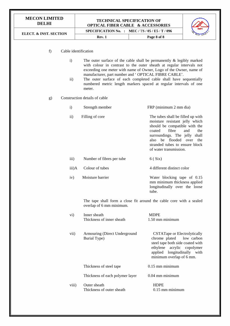
MECON LIMITED DELHI
TECHNICAL SPECIFICATION OF
OPTICAL FIBER CABLE & ACCESSORIES
SPECIFICATION No. : MEC / TS / 05 / E5 / T / 096 ELECT. & INST. SECTION
Rev. 1 Page 8 of 8
f) Cable identification
i) The outer surface of the cable shall be permanently & legibly marked
with colour in contrast to the outer sheath at regular intervals not exceeding one meter with name of Owner, Logo of the Owner, name of manufacturer, part number and ‘ OPTICAL FIBRE CABLE’.
ii) The outer surface of each completed cable shall have sequentially numbered metric length markers spaced at regular intervals of one meter.
g) Construction details of cable
i) Strength member FRP (minimum 2 mm dia)
ii) Filling of core The tubes shall be filled up with moisture resistant jelly which should be compatible with the coated fibre and the surroundings. The jelly shall also be flooded over the stranded tubes to ensure block of water transmission.
iii) Number of fibres per tube 6 ( Six) iii)A Colour of tubes 4 different distinct color
iv) Moisture barrier Water blocking tape of 0.15
mm minimum thickness applied longitudinally over the loose tube.
The tape shall form a close fit around the cable core with a sealed overlap of 6 mm minimum.
vi) Inner sheath MDPE Thickness of inner sheath 1.50 mm minimum vii) Armouring (Direct Underground CSTATape or Electrolytically
Burial Type) chrome plated low carbon steel tape both side coated with ethylene acrylic copolymer applied longitudinally with minimum overlap of 6 mm.
Thickness of steel tape 0.15 mm minimum Thickness of each polymer layer 0.04 mm minimum viii) Outer sheath HDPE Thickness of outer sheath 0.15 mm minimum

MECON LIMITED DELHI
TECHNICAL SPECIFICATION OF
OPTICAL FIBER CABLE & ACCESSORIES
SPECIFICATION No. : MEC / TS / 05 / E5 / T / 096 ELECT. & INST. SECTION
Rev. 1 Page 9 of 9
ix) Electrical continuity of the respective metallic layers shall be maintained between the ends of the cable in each cable drum.
X) Overall cable outer diameter shall not exceed 16 mm.
5.1.1.2 Mechanical Characteristics of cable a) Temperature
Installation & operation 0 Deg. C to 60 Deg. C Storage 0 Deg. C to 65 Deg. C
b) Tensile strength For CSTA, Direct underground The cable shall have burial Type OFC sufficient strength to
withstand a load of value T= 9.81W Newton, Where W = weight of 1Km of cable in Kg.
The load shall not produce total strain exceeding 0.25% in the fibre. c) Cable weight in Kg/Km Bidder to specify d) Minimum bending radius 20*Cable diameter
5.1.1.3 Average splice loss 0.01db/splice 5.1.1.4 Maximum overall diameter of the cable 16 mm 5.1.1.5 Cross sectional diagram of the cable is attached for reference as annexure - 1. Bidder
should submit the proposed / offered cross section diagram of the cable with the bid giving full details. It should confirm to general practice followed internationally.

MECON LIMITED DELHI
TECHNICAL SPECIFICATION OF
OPTICAL FIBER CABLE & ACCESSORIES
SPECIFICATION No. : MEC / TS / 05 / E5 / T / 096 ELECT. & INST. SECTION
Rev. 1 Page 10 of 10 TECHNICAL SPECIFICATIONS OF FIBRES TYPE I Single Mode Optical Fibre, Fully ITU T rec. G652 Oct 2000, IEC60793-1 and Telecordia GR – 20 Core Compliant
Sr. no Parameter Requirement
1.0 Transmission characteristics
1.1
Attenuation coefficient At 1310nm At 1550nm
≤0.35dB/Km ≤0.20dB/Km
1.2 Mode field diameter at 1310nm Nominal Tolerance
Any single value 8.6 – 9.5µm ± 0.7µm
1.3 Cut-off wavelength on 2 mt sample of fibre
≤1320
1.4 Chromatic dispersion 1285-1330nm 1270-1340 nm Zero dispersion wavelength Zero dispersion slope
≤3.5ps/nm-Km ≤5.3ps/nm. Km 1300 –1324nm ≤0.093ps/sqnm. Km
2.0 Dimensional Specification 2.1 Geometrical parameter
• Primary coating diameter • Cladding Diameter • Clad non-circularity • Mode field concentricity error
245 ± 10µ m 125 ± 1µ m ≤ 1% ≤ 0.8µ m
3.0 Mechanical Performance
3.1
Fibre Curl
4m
3.2
Fibre Proof test
1%
a) Protective materials/coatings
Optical fibres shall be coated with UV cured double Acrylate Resin. It should not have any
reaction with cladding or core material. Nominal overall thickness 250 µm The coatings should provide max. resistance to micro bending & abrasion and ensure mechanical & optical strength. The coatings shall be easily stripped with mechanical tools.
b) Fibre Identification
The coatings shall be in various distinct colours in order to facilitate fibre identification. Fibres colours shall correspond to IEC publication 793-2 and 304. The colours shall correspond reasonably with standard colours and shall readily be identifiable and shall be durable. The colours used should have fast colours properties and should not fade during the lifetime of cable. The coating and the colour shall not react with surrounding jelly. The vender shall take prior approval from HPCL for the colour scheme for fibre identification before commencement of manufacture of OFC.

MECON LIMITED DELHI
TECHNICAL SPECIFICATION OF
OPTICAL FIBER CABLE & ACCESSORIES
SPECIFICATION No. : MEC / TS / 05 / E5 / T / 096 ELECT. & INST. SECTION
Rev. 1 Page 11 of 11 TECHNICAL SPECIFICATIONS OF FIBRES TYPE II Single Mode Optical Fibre Type-I Fully ITU-T G-655 October’2000 and IEC60793-2 Complaint
Sr. no Parameter Requirement
1. Transmission characteristics
1.1
Attenuation coefficient At 1550nm At 1625nm
≤0.22dB/Km ≤0.25dB/Km
1.2 Mode field diameter Nominal Tolerance
Any Single value between 8-11µ m + 0.7µm
1.3
Cut-off wavelength on 2 mt sample of fibre
≤1480
1.4
Chromatic dispersion 1530-1565nm 1565-1625 nm Zero Dispersion wavelength Zero dispersion slope
0.1- 6 ps/nm-Km 4 – 11.2 ps/nm. Km ≤ 1530nm ≤ 0.080
1.5
Polarized Mode dispersion IN Cable, maximum individual fibre
≤ 0.15ps/√Km
1.6
Attenuation with bending 100 turns on a mandrel of 60mm diameter 1 turn on mandrel of 32mm diameter
≤ 0.05dB at 1550nm ≤ 0.5dB at 1550nm ≤ 0.6dB at 1625nm
3.0 Dimensional Specification
2.1
Geometrical parameter
1. Primary coating diameter 2. Cladding Diameter 3. Clad non-circularity 4. Mode field concentricity error 5. Effective area
245±10µ m 125 ± 1µ m ≤ 1% ≤ 0.8µ m ≥ 50squm.
4.0 Mechanical Performance
3.1 Fibre Curl
4m
3.2
Fibre Proof test
1%
MECON LIMITED DELHI
TECHNICAL SPECIFICATION OF
OPTICAL FIBER CABLE & ACCESSORIES
SPECIFICATION No. : MEC / TS / 05 / E5 / T / 096 ELECT. & INST. SECTION
Rev. 1 Page 12 of 12 a) Protective materials/coatings
Optical fibres shall be coated with UV cured double Acrylate Resin.
It should not have any reaction with cladding or core material.
The coatings should provide max. resistance to micro bending & abrasion and ensure mechanical & optical strength. The coatings shall be easily stripped with mechanical tools.
b) Fibre Identification
The coatings shall be in various distinct colours in order to facilitate fibre identification. Fibres colours shall correspond to IEC publication 793-2 and 304. The colours shall correspond reasonably with standard colours and shall readily be identifiable and shall be durable. The colours used should have fast colours properties and should not fade during the lifetime of cable. The coating and the colour shall not react with surrounding jelly. The vender shall take prior approval from HPCL for the colour scheme for fibre identification before commencement of manufacture of OFC.
5.1.3 OPTICAL FIBRE CABLE TESTS
The following minimum tests shall be conducted at the factory for the acceptance of the cable (Tests under item No. 5.1.3.1 shall be conducted by the Bidder on his own and test results send to the Owner/MECON for approval/review. Tests under item No. 5.1.3.2 shall be conducted by the Bidder in the presence of Owner/MECON only, after receiving test results under item no. 1)(In addition the Bidder shall provide Supplier's test certificate for the various types of raw materials used in manufacturing of this optical fibre cable):
5.1.3.1 Tests for fibre: Testing Test Reference
a) Core (mode field) diameter and AT ITU-T, G 652 & G.655
concentricity error
b) Cut-off wavelength AT ITU-T, G 652 & G.655
c) Attenuation coefficient c1) at 1300nm AT ITU-T, G 652 &
G.655 c2) at 1550nm AT ITU-T, G 652 &
G.655 C3) Spectral attenuation G.655 AT ITU-T d) Chromatic dispersion d1) at 1300 nm AT ITU-T, G 652 &
G.655 d2) at 1550nm AT ITU-T, G 652 &
G.655 d3) From 1530 to 1565nm G.655 AT ITU-T G.655

MECON LIMITED DELHI
TECHNICAL SPECIFICATION OF
OPTICAL FIBER CABLE & ACCESSORIES
SPECIFICATION No. : MEC / TS / 05 / E5 / T / 096 ELECT. & INST. SECTION
Rev. 1 Page 13 of 13
e) Cladding ei) Diameter AT ITU-T, G 652 &
G.655 eii) Non circularity AT ITU-T, G 652 &
G.655 5.1.3.2 Tests on completed cables: 5.1.3.2.1 Visual inspection:
a) Cable lay-up and fibre ST identification
b1) Identification and length marking ST on outer jacket.
b2) Colour contrast of the marking ST
with the outer sheath of the cables c) Overall diameter of the cable ST
5.1.3.2.2 Tests for moisture barrier:
a) Thickness of layers ST
b) Extent of overlapping ST
c) Electrical continuity of metallic AT layers
d) Water swellable tape or power AT e) Water immersion STIEC – 60793 – 1 – 53
5.1.3.2.3 Tests for corrugated steel tape armouring:
a) Thickness of layers ST
b) Extent of overlapping ST
c) Electrical continuity of AT metallic layers
b) Electrical discontinuity between AT CSTA and moisture barrier
5.1.3.2.4 Other tests:
a) Attenuation at 1310 nm & AT ITU-T, G. 652 1550 nm G.655
Polarization Mode dispersion ST ITU-T
b) Tensile performance ST IEC-794-1-E1
MECON LIMITED DELHI
TECHNICAL SPECIFICATION OF
OPTICAL FIBER CABLE & ACCESSORIES
SPECIFICATION No. : MEC / TS / 05 / E5 / T / 096 ELECT. & INST. SECTION
Rev. 1 Page 14 of 14
b1) CST-ECCSA, direct underground burial type O.F. Cable (with a tensile load of value T= 9.81 W Newton, where W = weight of 1 km `Cable' in kg).
c) Crush ST IEC-794-1-E3
(with 200 kg of load to be slowly placed and held for 60 seconds. The change in attenuation should not exceed 0.1dB/km)
d) Impact ST IEC-794-1-E4
(with a mass of 5 kg allowed to fall freely from 500 mm height on the cable sample 10 times repeatedly with a gap between one impact to another approximately at 60 seconds. The change in attenuation should not exceed 0.05dB/km)
e) Torsion ST IEC-794-1-E7
(with a weight of 7.5 kg attached to the stationery chuck and shall be subjected to 10 cycles. The change in attenuation should not exceed 0.05dB/km)
f) Bend ST IEC-794-1-E11
(To be performed preferably with Procedure 1 (of IEC) with a mandrel diameter of 24D mm, where D is the diameter of the cable and testing shall be done with 4 turns of cable wrapped and then unwrapped for 10 complete cycles. The change in attenuation should not exceed 0.05dB/km)
g) i) Snatch ST IEC-794-1-E9 With a load of 100 N. No damage to the fibre, sheath or to the other cable
elements. ii) Kink ST IEC-794-1-E10 Radius: 10*Cable diameter. No kink shall occur.
h) Temperature cycling ST IEC-794-1-F1
(This test shall be performed with a cable length of 200 m. Temperature cycle shall be taken as: i) at room temperature : 1 hr. ii) at zero degrees : 12 hrs. iii) at 65 degrees : 12hrs and iv) from 65 degrees to room temperature : 1 hr ) (The change in attenuation should not exceed 0.1dB/km)
i) Water penetration test ST IEC-794-1-F5 j) Water immersion ST IEC– 60793 – 53 k) Sheath integrity(Spark test) ST IEC-794-1-F3
The sheath shall withstand a spar test voltage of at least 8KVr.m.s. or 12 KVd.c.
MECON LIMITED DELHI
TECHNICAL SPECIFICATION OF
OPTICAL FIBER CABLE & ACCESSORIES
SPECIFICATION No. : MEC / TS / 05 / E5 / T / 096 ELECT. & INST. SECTION
Rev. 1 Page 15 of 15 LEGEND
AT : All to be tested
ST : Sample test ( 5% )
In case optical fibre cables, tested and inspected in accordance with this specification, fail to pass the test or comply with the specification requirement, the tests shall be repeated on a further representative set of cable pieces, and if it again fails, the whole lot shall be rejected subject to the discretion of the Owner/MECON.
Bidder shall provide detailed test procedures for each of the above-mentioned tests and may improve upon the same.
5.2 JOINTING CLOSURES
Jointing closures shall be suitable for the cables, as mentioned under clause 5.1. Jointing closures should be Dust tight (No dust ingress) and Protected against immersion in water (Suitable for continuous immersion in saline water) and should be complete with all accessories including splice cassettes splice protection and all other accessories including accessories for electrical continuity of metallic layers of optical fibre cable. The jointing closures shall be provided with suitable jointing pit support hardware to secure the jointing closures to a ~1200 mm dia. circular jointing pit.
Jointing Closure Tests
The following tests shall be conducted as a minimum:
a) Water Ingress Test
The cable-jointing box shall be assembled along with a continuous piece of cable passing through. The jointing box shall then be secured at the bottom of a immersion tank containing water upto a height of 2.0 m at normal room temperature for a period of 24 hours. The joint box will then be opened as per the specified procedure and visually examined for any ingress of water. It shall be declared to have passed the test in case there is no water present inside the box.
b) Impact test
The cable joint box shall be kept on a metal platform. A weight of 5 kgs spherical type having radius of R 50mm at striking end will be made to strike the box at the middle after having been released from a height of 500mm for 10 times. The joint box will be declared to have passed the test in case there are no cracks or fracture inside or outside of the box.
c) Drop and topple test
A drop test platform consisting of a steel plate not less than 6.5mm thick has to be used. The steel plate is bolted to a fully set concrete block at least 460mm thick. The joint box shall then be allowed to topple and fall freely from a height of 2000mm. The joint box will be declared to have passed the test in case there is no visible damage to the enclosure.
d) Pulling test
The joint box should be assembled with a long length of cable so that it can be pulled to the required tension of 200 kgs to check the strength of fixing arrangement inside the joint box.

MECON LIMITED DELHI
TECHNICAL SPECIFICATION OF
OPTICAL FIBER CABLE & ACCESSORIES
SPECIFICATION No. : MEC / TS / 05 / E5 / T / 096 ELECT. & INST. SECTION
Rev. 1 Page 16 of 16
e) Static load test
The assembled cable joint closure shall be kept on a platform with dimension more than that of cable joint closure. A curved hollow profiled mandrel shall be used for application of load and the mandrel shall be at the middle straight part of the joint closure. Weights shall be gradually placed on the mandrel till the weight becomes 250 kgs. The joint box shall be kept under the weight for a period of 24 hours. The joint closure shall be declared to have passed the test in case there is no visible damage.
Bidder shall provide detailed test procedures for testing Jointing Closures, and may improve upon the same.
6.0 GENERAL SPECIFICATIONS 6.1 VENDOR DATA REQUIREMENT AND DOCUMENTATION
a) Six sets of Documentation shall be supplied with each submission.
b) All documents shall be in English language only.
c) During system definition /engineering stage, owner/MECON shall review/approve drawings/documents to be mutually agreed with the vendor.
6.1.1 With the initial bid, the following documents shall be submitted:
1) Cable construction-showing cross section of the offered Optical fibre cable, providing details of each layer (Specifically mentioning, material used, thickness etc.).
2) Cable lifetime calculations. 3) Jointing Closure details.
6.1.2 The following documents for the complete system shall be supplied to
Owner/MECON in order to start Factory Acceptance Testing :
a) Following documents shall be supplied for review and approval (all under category ‘*’).
1) Detailed testing procedure for Optical fibre cable. 2) Detailed testing procedure for Joint closures & Test Instruments. 3) Quality Assurance program
4) Any other data, document not specifically mentioned, but required for the
satisfactory completion, operation and maintenance of the system shall be provided.
b) Following documents shall be supplied for information only.
1) Detail Technical manual of Joint closures and each type of
instruments/equipment containing circuit diagrams and description.
2) Maintenance manual of each type of instrument/equipment.

MECON LIMITED DELHI
TECHNICAL SPECIFICATION OF
OPTICAL FIBER CABLE & ACCESSORIES
SPECIFICATION No. : MEC / TS / 05 / E5 / T / 096 ELECT. & INST. SECTION
Rev. 1 Page 17 of 17 6.2 PACKING
All equipments/instruments/cable drums shall be individually packed in suitable containers/crates designed to avoid damage to the equipments during transit and storage in accordance with best commercial practice and with the requirements of applicable specifications. The materials used for packaging, wrapping. Sealing, moisture resistant barriers, corrosion preventers, etc. shall be of recognized brands and shall conform to best standards in the areas in which the articles are packaged. The packing shall protect the equipment from impact, vibration, rough handling, rain, dust, damp, insects, rodents, etc. Each container/crate shall be subjected to impact, vibration and other mechanical tests.
Each container shall have a copy of factory acceptance test report enclosed in it.
Packages for optical fibre cable shall make provision to allow for two (2) meters of excess cable on the inner end of the package to be accessed from outside. The outer end of the cable shall have pulling eye with heat shrinkable sleeves attached to it. The inner end of the cable shall be provided with a heat shrinkable sleeve. The ends shall be adequately protected to allow for normal handling during shipment.
6.4 QUALITY ASSURANCE PROGRAMME & TESTING
QUALITY ASSURANCE PROGRAMME
a) Vendor shall submit the details of Quality Assurance Programme followed by him beginning with raw materials, fabricated components, assemblies, etc. to finished product (AS APPLICABLE). Vendor shall obtain and forward the Quality Assurance Programme for equipment supplied by Sub-contractor, if any.
b) The owner, MECON and/or third appointed agency reserves the right to inspect
and test cable, jointing closures, etc at all stages of production and testing. The inspection and testing shall include but not be limited to materials, sub-assemblies, prototypes, produced units, guaranteed performance specifications, etc.
c) For Factory inspection and testing, Vendor shall arrange all that is required e.g.,
quality assurance personnel, space, test gear etc. for successful carrying out of the job by the Owner's representatives at Vendor's cost at the Vendor's/Manufacturer's works.
d) Owner's representatives shall have free entry and access to any and all parts of
the Vendor's facilities associated with manufacturing and testing of the system at any given time.
e) It shall be explicitly understood that under no circumstances shall any approval
of the Owner or his representatives relieve the Vendor of his responsibility for material, design, quality assurance and the guaranteed performance of the system and its constituents.
f) Vendor shall invite the Owner/MECON, at least 30 days in advance, of the date
on which system shall be ready for Inspection and Testing. All relevant documents and manuals; approved engineering drawings, etc. shall be provided to the Owner's representatives well in advance of the start of Inspection and Testing.

MECON LIMITED DELHI
TECHNICAL SPECIFICATION OF
OPTICAL FIBER CABLE & ACCESSORIES
SPECIFICATION No. : MEC / TS / 05 / E5 / T / 096 ELECT. & INST. SECTION
Rev. 1 Page 18 of 18
g) Owner/MECON shall, after completion of inspection and testing to their satisfaction, issue factory acceptance certificates to release the cable/jointing closures for shipment. No cable/jointing closures shall be shipped under any circumstances unless a factory acceptance certificate has been issued for it, unless agreed otherwise by Owner/MECON.
6.4.1 TESTING
a1) Optical Fibre Cable Factory testing shall be conducted for acceptance of the cable at the manufacturing facility, wherefrom cable is offered for this project before final acceptance, as per the approved test plan.
a2) Jointing closures
Jointing closures shall be tested before final acceptance, as per the approved test plan.
a3) Test Instruments
All test instruments shall be provided with calibration certificates. Test instruments shall be tested for functional operations, as per the approved test plan.
b) Vendor shall arrange all test equipments/instruments, manpower, test-gear,
accessories, etc., necessary for testing.
c) All technical personnel assigned by Vendor shall be fully conversant with the system specifications and requirements. They shall have the specific capability to make the system operative quickly and efficiently and shall not interfere or be interfered by other concurrent construction and commissioning activities in progress. They shall also have the capability to incorporate any minor modifications/suggestions put forward by MECON/Owner.
d) Power supply required for testing shall be arranged by the Vendor.
e) Test Plan
Vendor shall submit to Owner and MECON `Test Plans' well in advance of commencement of actual testing.
The plans shall include:
ei) Functional and performance description (in short) and Tests to be conducted and
purpose of test.
eii) Test procedures (including time schedule for the tests) and identification of test inputs details and desired test results.
f) Test Report
The observations and test results obtained during various tests conducted shall be compiled and documented to produce Test Reports by Vendor. The Test Reports shall be given for each equipment/item and system as a whole. The report shall contain the following information to a minimum:

MECON LIMITED DELHI
TECHNICAL SPECIFICATION OF
OPTICAL FIBER CABLE & ACCESSORIES
SPECIFICATION No. : MEC / TS / 05 / E5 / T / 096 ELECT. & INST. SECTION
Rev. 1 Page 19 of 19
fi) Test results. fii) Comparison of test results with anticipated test result as given in test plans and
reasons for deviations if any. fiii) The data furnished shall prove convincingly that:
I) The system meets the Guaranteed performance objectives. II) Mechanical/Optical/Electrical limits were not exceeded. III) Failure profile during the tests are well within the specified limits.
ANNEXURE Annexure ‘1’ : Cable Construction for 24 count CSTA Optical Fibre Cable
Annexure ‘2’ : Unpriced Bill of Materials.

MECON LIMITED DELHI
TECHNICAL SPECIFICATION OF
OPTICAL FIBER CABLE & ACCESSORIES
SPECIFICATION No. : MEC / TS / 05 / E5 / T / 096 ELECT. & INST. SECTION
Rev. 1 Page 20 of 20
Schematic Constructional Diagram For 24 Fibre OFC
Fibre colors : BI, Or, Gr,, Br, SL, Nat Loose Tube colours : BI, Or, Gr, Br Filler colors : Black/Natural Outer Diameter : 16 mm Maximum

MECON LIMITED DELHI
TECHNICAL SPECIFICATION OF
OPTICAL FIBER CABLE & ACCESSORIES
SPECIFICATION No. : MEC / TS / 05 / E5 / T / 096 ELECT. & INST. SECTION
Rev. 1 Page 21 of 21
Annexure ‘2’
Bill Of Quantity (Optical Fibre Cable and Associated Items) The bidder shall fill quoted for the list provided against each item in the un-priced offer of the bid (Bidder is required to quote for all items in this bid document) ---------------------------------------------------------------------------------------------------------------- Sl.No. Description Unit Quantity ---------------------------------------------------------------------------------------------------------------- A) SUPPLY
Supply of following items as per bid document: a) 24 fibre composite OF cable (G-655 & As per SOR
G-652) 4 Kms +/-5% cable drums. B) Supply of Joint Closures including all accessories (3M, SIEMENS, Raychem make)
a) For 24 fibre Composite OF cable As per SOR C) Special Tools and Tackles
Optical Fibre Cable preparation tool kit (Each set consisting of following, No. of sets as per SOR) 1. Three Wheel cutter (HDPE/ MDPE/ 1 No. CSTA/ ECCS etc. accurately 2. Sheath Cutter (for cutting sheath) 1 No. 3. Adjustible torgue wrench with adopter 1 No. 4. Adjustible Knife 1 No. 5. Hack-Saw (small) 1 No. 6. Armour punch 1 No. 7. Measuring tape - SS (3 meters) 1 No. 8. L-N key 1 No. 9. Cable Cutter 1 No. 10. Crosshead screw driver 1 No. 11. Flat head screw driver 1 No. 12. Combination Plier 1 No. 13. Scissors 1 No. 14. Flat spanners 1 No. 15. Loose tube cutter 1 No. 16. Stripper 1 No. 17. V-Groove 1 No. 18. Installation kit for splice closures 1 No. 19. Fibre Cleaver (Diamond cutter) 1 No. 20. 5 Meter pigtails with FC/ PC
Connector at one end 1 No. 21. 10 meter patch cord with FC/PC
Connector at one end 1 No.
22. Documentation 6 Sets. (Technical literature for Tools and Tackles)
MECON LIMITED DELHI
Technical Specification For Permanently
Lubricated Telecom HDPE Duct & Accessories
SPECIFICATION No. : MEC / TS / 05 / E5 / T / 037 ELECT. & INST. SECTION
Rev.1 Page 1 of 1
TECHNICAL SPECIFICATION FOR
PERMANENTLY LUBRICATED TELECOM HDPE DUCT & ACCESSORIES
Technical Specification No. : MEC / TS / 05 / E5 / T / 037
MECON LIMITED
DELHI - 110 092
1 28.06.2006 Sudhir Rakesh Shukla Pankaj Shrivastava
Revision Date Prepared by Checked by Approved by

MECON LIMITED DELHI
Technical Specification For Permanently
Lubricated Telecom HDPE Duct & Accessories
SPECIFICATION No. : MEC / TS / 05 / E5 / T / 037 ELECT. & INST. SECTION
Rev.1 Page 2 of 2
Contents
Sl. No. Description 1.0 Scope 2.0 Reference Documents 3.0 PLB HDPE Duct Specification 4.0 PLB HDPE Duct Accessories 5.0 Inspection & Testing 6.0 Identification Marking 7.0 Type Approval and Acceptance Test 8.0 Storage at Manufacturing Works 9.0 Quality Assurance Plan and Testing 10.0 Vendor Data Requirement and Documentation 11.0 Packaging and Delivery 12.0 Enclosures: 1. Table – I : Scale of Sampling for visual and
dimensional requirements. 2. Table – 2 : Sampling for Acceptance tests 3. Annexure – I : Oxidation Induction Test 4. Annexure – II : Internal Co-efficient of Friction 5. Data Sheet : Data Sheet for HDPE DUCT
MECON LIMITED DELHI
Technical Specification For Permanently
Lubricated Telecom HDPE Duct & Accessories
SPECIFICATION No. : MEC / TS / 05 / E5 / T / 037 ELECT. & INST. SECTION
Rev.1 Page 3 of 3
1.0 SCOPE This specification covers the minimum generic requirement of permanently self-
lubricated high Density Polyethylene ducts (PLB HDPE ducts) for use as underground conduits for optical fibre cables and associated accessories, suitable for installation of OFC by blowing technique.
The scope of work shall include supply of PLB HDPE ducts and the accessories as per the specification/ requirements given in this document. However Optical Fibre Cable shall be laid in a permanently lubricated HDPE pipe using blowing technique.
1.1 Supply of special tools and tackles as mentioned in the bills of quantity. 1.2 Supply of complete technical literature and documentation as defined in Section 10. 1.3 Quality Assurance and testing as described at section 9, to the complete satisfactory of
the Owner/ Consultant and/or third appointed agency. 2.0 REFERENCE DOCUMENTS Unless otherwise specified, this document requires references to the latest standards of
the following:
IS 2530 Methods for test for Polyethylene Molding Materials and Polyethylene Compounds
IS 4984 High Density Polyethylene Pipes for water supply IS 7328 High Density Polyethylene materials for molding and
extrusion IS 9938 Recommended colours for PVC insulation for LF wires and
cables IS 12235 (Part – 9) Methods of test for unplasticized PVC pipes for potable
water supplies – Impact strength at 0°C IS 14151 (Part – 1) Ployethylene pipes for sprinkler irrigation systems (Part – I
Pipes) ASTMD 1693 Test method for environmental stress cracking of ethylene
plastics. 3.0 PLB HDPE Duct Specification : 3.1 The PLB HDPE duct shall consist of two concentric layers, the outer layer being HDPE,
co-extruded with an inner layer of solid permanent lubricant, to reduce the internal co-efficient of Friction (ICF). The lubricant shall be of a solid layer of uniform thickness so formulated to provide a permanent, low friction boundary layer between the inner surface
MECON LIMITED DELHI
Technical Specification For Permanently
Lubricated Telecom HDPE Duct & Accessories
SPECIFICATION No. : MEC / TS / 05 / E5 / T / 037 ELECT. & INST. SECTION
Rev.1 Page 4 of 4
of the duct and Optical Fiber cable. The lubricant layer shall be clearly visible in cross-section, concentric with the outer layer.
3.2 Alternatively the duct can be of a homogenous construction (without a separate inner
layer) meting all the requirements of this specification. 3.3 The PLB HDPE duct shall be supplied in a continuous length in coil form, suitable for
shipping and handing purposes. 3.4 MATERIAL 3.4.1 Two Layer Construction 3.4.2 Outer Layer
The base HDPE rein used for the outer layer of the PLB HDPE duct shall conform to any designation of IS – 7328 or to any equivalent standard meeting the following requirements, when tested as per IS – 2530. However, the manufacturers shall furnish the designation for the HDPE resin as permanently IS – 7328 as applicable. a) Density : 0.940 TO 0.958 g/cc AT 27°C B) Melt Flow Rate (MFR) : 0.2 to 1.1 g/10 minutes at 190°C & 6 kg
load.
3.4.3 Inner Layer
The inner lubrication material shall be of friction reducing, polymeric material which shall be integral with HDPE layer. The lubricant materials shall have no toxic or dermatic hazards for safe handling. In the finished PLB HDPE duct, the co-extruded layer of solid permanent lubricant shall be integral part with HDPE and shall be white in colour and clearly visible in cross-section of duct.
3.4.4 The inner layer of solid permanent lubricant shall be continuous all through and shall not
come out during storage, usage and throughout the life of the duct. 3.5 Homogenous Construction:
The HDPE material used for this construction shall meet the requirements listed in clause 4.1.1, such that the finished duct shall satisfy the internal Co-efficient of friction (ICF) and all other requirements of this specification.
3.6 The raw material (s) used for the duct shall meet the following requirements :
i) The anti-oxidants used shall be physiologically harmless.
MECON LIMITED DELHI
Technical Specification For Permanently
Lubricated Telecom HDPE Duct & Accessories
SPECIFICATION No. : MEC / TS / 05 / E5 / T / 037 ELECT. & INST. SECTION
Rev.1 Page 5 of 5
ii) None of the additives shall be used separately or together in quantities as to
impair long term physical and chemical properties of the duct. iii) Single pass rework material of the same composition produced from the
manufacturer’s own production shall be used and it shall not exceed 10% in any case.
iv) The raw material used for extrusion shall be dried the moisture content to less than 0.1%.
v) Suitable UV stabilizers shall be used for manufacturer of the duct to protect against ultra violet degradation, when stored in open for a minimum period of 8 months.
vi) The raw material used in the manufacturer of the duct shall be such that the service life of the duct and all its accessories can be expected to be more than 50 years including the life of permanent lubricant.
4.0 PLB HDPE DUCT ACCESSORIES 4.1 The following accessories are required for jointing the ducts and shall be supplied along
with the ducts. The manufacturers shall provide complete design details, procedure for method of installation and type/ grade of the material used for the accessories. The qty. will be as per material requisition (MR). a) Plastic Coupler
It is used to couple two ducts. The design of this shall be simple, easy to install and shall provide airtight and water tight joint between the two ducts. The coupler shall ensure that the two ducts are butted smoothly without any step formation in the inner surface. The jointing shall meet the air pressure test of 10 kg/cm2 for a minimum period of 2 hours without any leakage.
b) End Plug.
This is for sealing the ends of the empty ducts, prior to installation of the Optical Fiber Cable and shall be fitted immediately after laying of the duct, to prevent the entry of any dirt, water, moisture, insects/ rodents etc.
c) Cable Sealing Plug This is used to seal the ends of the ducts perfectly, after the cable is installed in the duct, to prevent the entry of dirt, water, moisture, insects/ rodents etc. This is required at all places where cable has come out of the duct either for jointing or entry into the building as required. The sealing plug shall be capable of accommodating standard sizes of optical fibre cable taking into account the variation in diameter due to tolerance limits, etc.
MECON LIMITED DELHI
Technical Specification For Permanently
Lubricated Telecom HDPE Duct & Accessories
SPECIFICATION No. : MEC / TS / 05 / E5 / T / 037 ELECT. & INST. SECTION
Rev.1 Page 6 of 6
d) End Cap
This cap is made of hard rubber, shall be fitted into both ends of duct coil after manufacturing the duct. This shall avoid entry of duct, mud and rainwater into the duct during the transit and storage.
Note: The Accessories in clause 6.1 (b) and (c) shall be tested for air tightness with a pressure of 1 bar for 30 minutes. For carrying out the tests for the above accessories suitable length of duct shall be taken.
4.2 The following additional tools are required for jointing for the ducts and
installation for optical fibre cable. These items can be procured as per the Manufacturer/ Supplier’s specification, as and when required by the Owner.(This is required if exclusively mention in the Material Requisition).
a) Duct Cutter
This is required to cut the duct ends squarely without any burr or notch.
b) C-Spanner
This is required to tighten Plastic Coupler properly so as to ensure air/water tightness as specified above.
c) Blowing Equipment
The equipment used for installing optical fibre cable by blowing technology shall be capable of pushing 1 km (minimum) cable into the duct with powerful air stream generated by a compressor. The compressor shall have the following characteristics: Pressure : Min 8 bar Max. 12 bar Flow rate : 10 m3/ minute
The mechanical feeder of the equipment shall not cause any damage to the sheath/ jacket of the optical fibre cable.
5.0 INSPECTION AND TESTS:
The manufacturer shall perform all inspection and test as per the requirements of this specification and the relevant codes, prior to shipment at this works. Such inspection and test shall be, but not limited to the following:
MECON LIMITED DELHI
Technical Specification For Permanently
Lubricated Telecom HDPE Duct & Accessories
SPECIFICATION No. : MEC / TS / 05 / E5 / T / 037 ELECT. & INST. SECTION
Rev.1 Page 7 of 7
5.1 Visual Inspection The ducts shall be checked visually for ensuring good workmanship that the ducts shall
be free from blisters, shirks hole, flaking, chips, scratches, roughness, break and other defects. the ducts shall be smooth, clean, round. The ends shall be cleanly cut and shall be square with axis of the duct.
5.2 The colour of the duct shall be green and uniform throughout. Each duct shall contain 4
approximately equi-spaced continuous longitudinal stripes of width 3-mm minimum in white colour. These stripes shall be co-extruded during manufacturing. The material of the stripes shall be same as that of base compound for the duct.
5.2.1 In the case of two layer construction the inner layer (Soil Lubricant) shall be white in
colour. 5.2.2 The colours of the duct, stripe and inner layer (in the case of two layer construction) shall
be identifiable under normal lighting conditions and generally conform to IS-9938. 5.3 Dimension of Ducts
The nominal size of the ducts shall be 40/33 mm & 32/26 mm and shall meet the following requirements. 40 mm/ 33 mm 32 mm/ 26 mm a) Outside diameter 40 mm + 0.4 mm 32 mm + 0.3 mm b) Wall thickness 3.5 mm ± 0.2 mm 3.0 mm ± 0.2 mm c) Standard length 1000 ± 100 mtr. 1000 ± 100 mtr. d) Maximum Outer 16 mm 12 mm Diameter of Optical Fiber Cable (OFC) that can be Installed by air blowing Technique Note: Selection of duct size will depend on the outside diameter of the Optical Fiber Cable (OFC) to be installed.
5.4.1 Tensile Strength and Elongation
The samples removed from the PLB HDPE ducts when tested as permanently IS-14151 (Part – I) shall meet the following requirements.
MECON LIMITED DELHI
Technical Specification For Permanently
Lubricated Telecom HDPE Duct & Accessories
SPECIFICATION No. : MEC / TS / 05 / E5 / T / 037 ELECT. & INST. SECTION
Rev.1 Page 8 of 8
Tensile Strength : Min 20 N/mm2
Elongation : Min. 350%
5.4.2 Reversion Test:
The test shall be carried out as per IS-4984. For this purpose, a duct length of 200 mm shall be placed horizontally in an air-oven or a suitable liquid bath on a support at 110 ± 2°C for 60 minutes so that the dimensional change in duct section are not impeded. After cooling to room temperature the dimensional change of the duct section shall be measured in the longitudinal direction and the deviation from the initial length shall be calculated and stated in percentage. The dimensions shall not changes by more than 3% in the longitudinal direction.
5.4.3 Environmental Stress Crack Resistance Test:
The specimen cut from the PLB HDPE ducts shall meet the environmental stress cracking as described in ASTM D-1693, when tested with 10% Igepal (CO 630) solution at 50 ±1°C for 96 hours. There shall be no failure.
5.4.4 Impact Strength Test:
The test has to be carried as per IS-12235 (Part – 9). A sample duct 150 mm in length shall be placed on heavy rigid block whose faces are at an angle of 120°. A striker with a hemispherical nose of 13 mm radius and loaded to a total weight of 10 kg shall be allowed to fall freely in a suitable vertical guides through a height of 1.5 m before striking the duct. The line of fall of the striker shall coincide with the diameter of the duct. The duct shall not crack or split.
5.4.5 Crush Resistance Test :
Samples of duct of 150 mm ± 2 mm in length shall be subjected to a dead load of not less than 50 kg for one minute and shall be allowed to recover for 5 minutes. The deflection with load on and after recovery period shall not exceed 10% and 2% respectively.
5.4.6 Mandrel Test:
A 150 mm long mandrel of diameter, 3 mm less than the internal diameter of the duct shall be passed through a 5 meter length of duct, freely throughout the length, when the duct is bent to a radius of 5 meters.

MECON LIMITED DELHI
Technical Specification For Permanently
Lubricated Telecom HDPE Duct & Accessories
SPECIFICATION No. : MEC / TS / 05 / E5 / T / 037 ELECT. & INST. SECTION
Rev.1 Page 9 of 9
5.4.7 Ovality Test:
Ovality is the difference between maximum outside diameter and the minimum outside diameter at the same cross-section of the duct, at 300 mm away from the end. The ovality for 40/33 mm and 32/26 mm ducts, when measured as per IS_4984 shall not exceed 1.4 mm and 1.3 mm respectively.
5.4.8 Coil Set Test :
The PLB HDPE duct shall unroll of the drums without snaking or waving having zero coil set. Thus the duct shall lay straight into the trench without re-coiling. For this purpose, when a minimum length of 50 meters duct taken from the coil and laid on the ground, it shall be straight without any bends or kinks and without deformation, except 5 meters from each end.
5.4.9 Oxidation Induction Test:
The induction time in oxygen when tested with a copper pan as per method in Annexure – I, shall not be less than 30 minutes.
5.4.10 Hydraulic Characteristics :
The duct shall be tested for internal pressure creep rupture test as per IS-4984. For this purpose, a sample length of 10 times the outside diameter of the duct shall be taken. At the end of the test, the sample shall not shown signs of localised swelling or leakage and shall not burst during the test duration. The test showing failure within a distance equivalent to the length of end cap from the end shall be disregarded and the test repeated. The test temperature and the duration of the test shall be as follows:
Test Test Temp °C Test Duration (Hrs.) (Min, holding time)
Induced Stress (Mpa)
Type Test 80 165 3.5 Acceptance test 80 48 3.8
5.4.11 Internal Co-efficient of Friction:
The internal Co-efficient of Friction when tested as permanently method in Annxurer – II, shall not exceed 0.06, when tested with respect to Nylon jacketted unarmored Optical Fiber Cable i.e., 24 F Fiber or 12 F as required.
5.4.12 Optical Fiber Cable Blowing Test:
For this test an Optical fiber Cable of a diameter nearest to the diameter indicated in this specification, relevant to the size of duct under test shall be installed by blowing of the cable in a length of 1 km of the duct. The duct shall be laid with bends in the horizontal
MECON LIMITED DELHI
Technical Specification For Permanently
Lubricated Telecom HDPE Duct & Accessories
SPECIFICATION No. : MEC / TS / 05 / E5 / T / 037 ELECT. & INST. SECTION
Rev.1 Page 10 of 10
and vertical planes and a raise in the middle. The 1 km section shall include two couplings at suitable locations.
The OFC shall then be blown out. It shall be inspected for any visual damage. The OFC shall then be blown in again.
It shall be possible to blow in the Optical Fiber Cable through the 1 km duct, each time in not more then 30 minutes. There shall be no visible damage to OFC.
The test will be conducted on two samples out of the five submitted for Type Approval. 5.4.13 Owner/ Consultant reserves the right to perform stage – wise inspection and witness tests
as indicated above at manufacturer’s works prior to shipment. Manufacturer shall give reasonable access and facilities required for inspection to the Owner / Consultant Inspector.
Owner/ Consultant reserved- the right to require additional testing at any time to confirm or further investigation a suspected fault. The cost incurred shall be to manufacturer’s account. In no case shall any action Owner/ Consultant or his Inspector relive the manufacturer of his responsibility for material, design, quality etc. Inspection and test performed / withered by the Owner/ Consultant Inspector shall in no way relieve the manufacturer’s obligation to perform the required inspection and test.
5.4.14 Test Certificate
Manufacturer shall submit all the test report of the test performed as per above requirement. The certificates shall be valid only when signed by Owner/ Consultant Inspector. Only the certificate material shall be dispatched from manufacturer works.
6.0 IDENTIFICATION MARKINGS
The duct shall be prominently marked with indelible link, with the following information at intervals every meter to enable identification of the pipe. The size of ink markings shall be distinct, clearly and easily visible. Client Name Client Logo Manufacturer’s Name (Also can be abbreviated form) Name of the duct with size Machine number/ specific serial number of the duct Date of manufacturing Sequential length marking at every meter.
MECON LIMITED DELHI
Technical Specification For Permanently
Lubricated Telecom HDPE Duct & Accessories
SPECIFICATION No. : MEC / TS / 05 / E5 / T / 037 ELECT. & INST. SECTION
Rev.1 Page 11 of 11
7.0 TYPE APPROVAL AND ACCEPTANCE TEST : 7.1 All the tests mentioned in this document shall be carried out on the 5 standard lengths of
ducts and the samples must pass these tests before according the type approval. The supplier shall furnish 5 standard length for carrying out these tests for according type approval. Bulk manufacturer and supply shall start only after issue of type approval. The type approval certificate shall clearly indicated the type/ grade/ source of high-density polyethylene raw material, the size of the duct and the construction of the duct i.e., Two layer of Homogenous.
7.2 Fresh type approval shall be obtained whenever grade/ source of raw material HDPE
resin or Solid Lubricant is changed. 7.3 Acceptance Tests 7.3.1 The acceptance tests shall be carried out on samples from the lot as per Table – 1 for
Dimensional and Visual requirements. The requirements for Tensile Strength & Elongation, Reversion Test, Environmental Stress Crack resistance, Impact Strength, Crush resistance, Oxidation Induction Test, Hydraulic Characteristics and internal Co-efficient of Friction shall be carried out as per Table – 2.
7.3.2 The Owner at his discretion at any point of time can modify the acceptance tests and the
sampling plan. 8.0 STORAGE
All the material shall be stores in the manufacturer’s premises in such a manner that it will not affect the performance of the product.
9.0 QUALITY ASSURANCE PROGRAM & TESTING 9.1 Quality Assurance Program
a) Vendor shall submit the details for Quality Assurance Program followed by him beginning with raw materials, fabricated components, assemblies, etc., to finished product (AS Applicable). Vendor shall obtain and forward the Quality Assurance Program for equipment supplied by Sub-contractor.
b) The Owner/ Consultant and/ or third appointed agency reserves the right to
inspect and test duct and accessories etc. at all stages of production and testing. The inspection and testing shall include but not be limited to materials, sub-assemblies, prototypes, produced units, guaranteed, performance specifications etc.
MECON LIMITED DELHI
Technical Specification For Permanently
Lubricated Telecom HDPE Duct & Accessories
SPECIFICATION No. : MEC / TS / 05 / E5 / T / 037 ELECT. & INST. SECTION
Rev.1 Page 12 of 12
c) For factory inspection and testing, vendor shall arrange all the is required e.g.,
quality assurance personnel spaces, test gear etc., for successful carrying out of the job by the Owner’s respectively at vendor’s cost at the vendor’s/ Manufacturer ‘s works.
d) Owner’s representatives shall have free entry and access to any and all parts of
the Vendor’s facilities associated with manufacturing and testing of the system at any given time.
e) It shall be explicitly understood that under no circumstances shall any approval
of the Owner or his representatives relieve the vendor of his responsibility of material, design, quantity assurance and the guaranteed performance of the system and its constants.
f) Vendor shall invite the Owner/ Consultant, at least 30 days in advance, of the
date on which material shall be ready for inspection and testing. All relevant documents and manuals approved engineering drawings, etc shall be provided to the Owner’s / consultant’s representative’s well in advance of the start of inspection and Testing.
g) Owner/ Consultant shall, after completion of inspection and testing to their
satisfactory, issues factory acceptance certificate to release duct / accessories for shipment. No. Duct / accessories shall be shipped under any circumstances unless a factory acceptance certificate has been issued for it, unless agreed otherwise by Owner/ Consultant.
h) PLB HDPE Duct Testing
Factory testing shall be conducted for acceptance of the duct at the manufacturing facility, wherefrom duct is offered for this project before final acceptance, as per the approval test plan
i) Accessories Testing :
Accessories shall be tested before final acceptance, as per the approved test plan.
j) Test Instruments :
i) Vendor shall arrange all test equipment’s/ instruments, manpower, test-gear, accessories etc. necessary for testing.
ii) All technical personnel assigned by vendor shall be fully conversant with the system specifications and requirements. They shall have the specific capability to make the system operative quickly and efficiently and shall not interface or be interfered by other concurrent construction and commissioning activities in progress. They shall also have the capability
MECON LIMITED DELHI
Technical Specification For Permanently
Lubricated Telecom HDPE Duct & Accessories
SPECIFICATION No. : MEC / TS / 05 / E5 / T / 037 ELECT. & INST. SECTION
Rev.1 Page 13 of 13
to incorporate any minor modification/ suggestions put forward by Owner/ Consultant.
iii) Power supply required for testing shall be arranged by the vendor
iv) Test Plane
Vendor shall submit to owner and consultant ‘Test Plans’ well in advance of commencement of actual testing. The plans shall include: - Functional and performance description (in short) and tests to be
conducted and purpose of test. - Test procedures (including time schedule for the tests) and
identification of test inputs details and desired test results.
v) Test report
The observation and test results obtained during various tests conducted shall be complied and documented to produce test reports by vendor. The test reports shall be given for each equipment / items and system as a whole. The report contain the following information to a minimum/
vi) Test Results
- Comparison of tests results with anticipated test result as given in test plans and reasons for deviations if any,
- The data furnished shall prove convincingly that: - The system meets the Guaranteed performance objective. - Mechanical/ Optical/ Electrical limits were not exceeded. - Failure profiles during the tests are well within the specified
limits. 10.0 VENDOR DATA REQUIREMENTS AND DOCUMENTATION 10.1 All the documents shall be is English language only. 10.2 Six sets of documents shall be supplied with final submission. 10.3 With the initial bid, the following documents shall be submitted
i) Duct Construction Details and Duct Life. ii) Accessories Details. iii) Technical Literature etc.

MECON LIMITED DELHI
Technical Specification For Permanently
Lubricated Telecom HDPE Duct & Accessories
SPECIFICATION No. : MEC / TS / 05 / E5 / T / 037 ELECT. & INST. SECTION
Rev.1 Page 14 of 14
10.4 Following documents shall be supplied to Owner/ Consultant in order to start Factory
Acceptance Testing
a) For Review Approval
i) Detailed Testing procedure for Duct. ii) Detailed test procedure for accessories iii) Quality assurance program iv) Any other data/ documents not specifically mentioned but required for
the satisfactory completion of the work
b) For Information
i) Detail technical Literature and manuals for duct & accessories ii) Installation, Maintenance & Operation Instruction Manual for all the
supply items 11.0 PACKAGE AND DELIVERY The store shall be supplied in coils of suitable size for delivery in such a manner that they
arrive at their distribution in a safe and undamaged condition and will permit the loading, unloading and handing the stores using standard moving equipment. The minimum inner bending diameter of technical coiled duct shall be 25 times the outer diameter of the cut. The material used for packaging wrapping sealing, moisture, resistant, corrosion prevents etc. as per applicable shall be of recognized brands and shall conform to best standards for packaging. The packing shall protect the material from impact vibration rough handling rain, dust, damp, insects, rodents etc., Each packing should have packing slip and test dispatch clearance documents.
_____________

MECON LIMITED DELHI
Technical Specification For Permanently
Lubricated Telecom HDPE Duct & Accessories
SPECIFICATION No. : MEC / TS / 05 / E5 / T / 037 ELECT. & INST. SECTION
Rev.1 Page 15 of 15
Table – 1
SCALE OF SAMPLING FOR VISUAL AND DIMENSIONAL, REQUIREMENTS No. of coils (Duct) in
the Lot Sample No. Sample Size Cumulative
Sample Size Acceptance
No. Rejection No.
(1) (2) (3) (4) (5) (6) Up to 150 First
Second
13
13
13
26
0
1
2
2 151 to 280 First
Second
20
20
20
40
0
3
3
4 281 to 500 First
Second
32
32
32
64
1
4
4
5 501 to 1200 First
Second
50
50
50
100
2
6
5
7 1201 to 3200 First
Second
80
80
80
160
3
8
7
9 3201 to 10000 First
Second
125
125
125
250
5
12
9
13 10001 to 35000 First
Second
200
200
200 400
7
18
11
19 Criteria: The number of ducts given for the first sample in Column 3 shall be examined for
dimension and visual requirements. A duct failing to satisfy any of these requirements shall be considered as defective. The lot shall be deemed to have satisfied these requirements, if the number of defectives found in the first sample are less than or equal to the corresponding acceptance number given in Column 5. The lot shall be deemed not to have met these requirements of the number of defectives found in the first sample is greater than or equal to the corresponding rejection number given in Column 6. If, however, the number of defectives found in the first sample, lies between the corresponding acceptance and rejection numbers given in Column 5 and 6, the second sample of the size given in Column 3 shall be taken and examined for these requirements. The lot shall be considered to have satisfied these requirements, if the number of defectives found in the cumulative sample is less than or equal to the corresponding acceptance number given in Column 5 otherwise not.
MECON LIMITED DELHI
Technical Specification For Permanently
Lubricated Telecom HDPE Duct & Accessories
SPECIFICATION No. : MEC / TS / 05 / E5 / T / 037 ELECT. & INST. SECTION
Rev.1 Page 16 of 16
TABLE – 2
SAMPLING FOR ACCEPTANCE TESTS
A separate sample size for each of the tests shall be taken as stipulated at random from the samples already examined for dimensions and visual inspection. All the ducts in each of the sample size shall be tested for compliance for the requirements for as per clause no. 5.4 of technical specification:
(a) Tensile Strength & Elongation (b) Reversion Test (c) Environmental Stress Crack Resistance (d) Impact Strength (e) Crush Resistance (f) Oxidation Induction Test (g) Hydraulic Characteristics (h) Internal Co-efficient of Friction
The lot shall be considered to have met the requirements of these tests, if none of samples tested fails.
No. of Coils Sample Size
Up to 150 3
151 to 1200 5
1201 to 35000 8
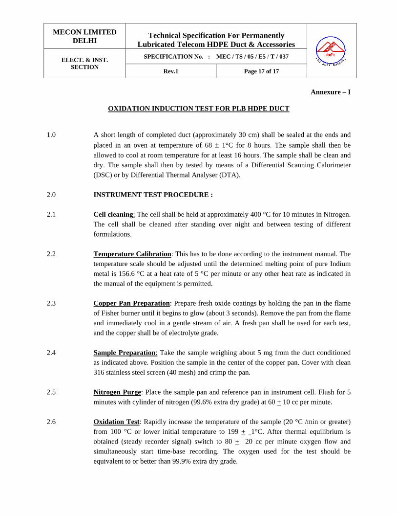
MECON LIMITED DELHI
Technical Specification For Permanently
Lubricated Telecom HDPE Duct & Accessories
SPECIFICATION No. : MEC / TS / 05 / E5 / T / 037 ELECT. & INST. SECTION
Rev.1 Page 17 of 17
Annexure – I
OXIDATION INDUCTION TEST FOR PLB HDPE DUCT
1.0 A short length of completed duct (approximately 30 cm) shall be sealed at the ends and
placed in an oven at temperature of 68 ± 1°C for 8 hours. The sample shall then be
allowed to cool at room temperature for at least 16 hours. The sample shall be clean and dry. The sample shall then by tested by means of a Differential Scanning Calorimeter (DSC) or by Differential Thermal Analyser (DTA).
2.0 INSTRUMENT TEST PROCEDURE : 2.1 Cell cleaning: The cell shall be held at approximately 400 °C for 10 minutes in Nitrogen.
The cell shall be cleaned after standing over night and between testing of different formulations.
2.2 Temperature Calibration: This has to be done according to the instrument manual. The
temperature scale should be adjusted until the determined melting point of pure Indium metal is 156.6 °C at a heat rate of 5 °C per minute or any other heat rate as indicated in the manual of the equipment is permitted.
2.3 Copper Pan Preparation: Prepare fresh oxide coatings by holding the pan in the flame
of Fisher burner until it begins to glow (about 3 seconds). Remove the pan from the flame and immediately cool in a gentle stream of air. A fresh pan shall be used for each test, and the copper shall be of electrolyte grade.
2.4 Sample Preparation: Take the sample weighing about 5 mg from the duct conditioned
as indicated above. Position the sample in the center of the copper pan. Cover with clean 316 stainless steel screen (40 mesh) and crimp the pan.
2.5 Nitrogen Purge: Place the sample pan and reference pan in instrument cell. Flush for 5
minutes with cylinder of nitrogen (99.6% extra dry grade) at 60 + 10 cc per minute.
2.6 Oxidation Test: Rapidly increase the temperature of the sample (20 °C /min or greater) from 100 °C or lower initial temperature to 199 + 1°C. After thermal equilibrium is obtained (steady recorder signal) switch to 80 + 20 cc per minute oxygen flow and simultaneously start time-base recording. The oxygen used for the test should be equivalent to or better than 99.9% extra dry grade.

MECON LIMITED DELHI
Technical Specification For Permanently
Lubricated Telecom HDPE Duct & Accessories
SPECIFICATION No. : MEC / TS / 05 / E5 / T / 037 ELECT. & INST. SECTION
Rev.1 Page 18 of 18
2.7 Induction Period: The oxygen induction point shall be recorded as time zero, and the chart speed shall be sufficient to provide a clearly discernible slope at the start of the exothermic reaction. The test in the pure dry oxygen atmosphere shall continue until the exothermic peak is produced. The intersection of the tangent of the exothermic sloped line with the extended base line will be drawn. The time form time zero to this intersection point is read from the base line and recorded as the oxidative induction time.
----------------------

MECON LIMITED DELHI
Technical Specification For Permanently
Lubricated Telecom HDPE Duct & Accessories
SPECIFICATION No. : MEC / TS / 05 / E5 / T / 037 ELECT. & INST. SECTION
Rev.1 Page 19 of 19
Anenxure – 2
INTERNAL CO-EFFICIENT OF FRICTION TEST FOR PLB HDPE DUCT
1. SCOPE: These procedure details the method employed to determine internal friction properties of the duct.
2. APPARATUS : Extensometer machine, circular test fixture of diameter 750 mm (capable of having secured to it), 25 kg weight, optical fibre cable and pulley wheel.
3. METHOD:
a) A suitable length of the duct, per-conditioned at 23 + 2°C for 2 hours, shall be secured to the text fixture such that the sample completes a 450°C wrap. With one end extending vertically 200 mm towards the floor.
b) A suitable length of optical fibre cable shall be inserted into the sample. c) The extensometer and the test fixture shall be aligned and secured from
movement. d) The 25 kg tail weight shall be attached to the optical fibre cable extending from
the 200 mm vertical extension of the sample such that there is a minimum free travel of 150 mm for the weight.
e) The other end of the optical fibre cable shall be attached via a pulley, to the extensometer such that the planes of travel are in no direction diagonal and there shall be slack remaining in the optical fibre cable.
f) The extensometer shall be operated, and the maximum load applied, in lifting the 25 kg weight to a minimum travel of 150 mm shall be noted.
g) Extensometer conditions Load : kg or Newtons Speed : 500 mm / minute Mode : Tension
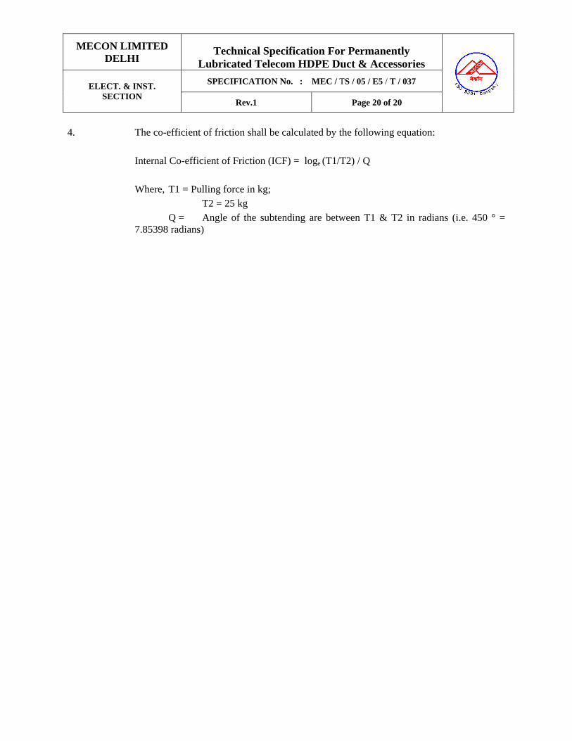
MECON LIMITED DELHI
Technical Specification For Permanently
Lubricated Telecom HDPE Duct & Accessories
SPECIFICATION No. : MEC / TS / 05 / E5 / T / 037 ELECT. & INST. SECTION
Rev.1 Page 20 of 20
4. The co-efficient of friction shall be calculated by the following equation:
Internal Co-efficient of Friction (ICF) = loge (T1/T2) / Q Where, T1 = Pulling force in kg; T2 = 25 kg
Q = Angle of the subtending are between T1 & T2 in radians (i.e. 450 ° = 7.85398 radians)

MECON LIMITED DELHI
Technical Specification For Permanently
Lubricated Telecom HDPE Duct & Accessories
SPECIFICATION No. : MEC / TS / 05 / E5 / T / 037 ELECT. & INST. SECTION
Rev.1 Page 21 of 21
PERMANENTLY LUBRICANT HDPE TELECOM DUCT
(PLB HDPE Duct)
1.0 Design/ Manufacturing : AS per the technical Specification
Requirements. 2.0 Outer Diameter : 40 mm 3.0 Pressure Rating : Min 6 kg/cm2 4.0 Wall Thickness : 4.0 ± 0.3 mm 5.0 Tensite Strength : 20 N/ mm2 or better 6.0 Density : 940 - 950 kg/m3 at 27°C 7.0 Melt Flow Index : 0.4 to 0.95 gm/10 minutes at 90°C under 5 kg
load. 8.0 Intrinsic Coefficient of Friction : 0.06 (max.) when tested with
respect to Nylon. 9.0 Impact Strength : As per IS : 12235 (Part – 9), 1989 10.0 Confirmation to Standards : As per IS : 7328 ( Latest) As per IS : 2530 As per IS : 9938 As per IS : 4984 As per IS : 1693 As per ASTM D : 1693 11.0 Quantity : As per SOR
****************

MECON LIMITED Delhi
ELECT & INST SECTION
TECHNICAL SPECIFICATION FOR
WARNING MATS FOR OFC LAYING
TECHNICAL SPECIFICATION NO. : MEC/TS/05/E5/042 REV-0 Page 1 of 3
ELECTRICAL & INSTRUEMNTATION SECTION MECON LIMITED DELHI 110 092
TECHNICAL SPECIFICATION FOR
WARNING MATS FOR OFC LAYING
SPECIFICATION NO. : MEC/TS/05/E5/042, Rev-0
0 06.06.2009 R Sanjay Rakesh Shukla Pankaj Shrivastava
Revision Date Prepared by Checked by Approved by

MECON LIMITED Delhi
ELECT & INST SECTION
TECHNICAL SPECIFICATION FOR
WARNING MATS FOR OFC LAYING
TECHNICAL SPECIFICATION NO. : MEC/TS/05/E5/042 REV-0 Page 2 of 3
Purpose : For using as a warning sign for Under Ground Natural Gas Pipeline
Width : 300 mm Thickness : 1.00 mm thick Material of the mat : The material shall be of high density Polyethylene. It
shall have Anti – Rodent properties. Colour of the mat : Golden Yellow with letters in RED Art Work : A sample piece of 30mm wide and 200mm long of every
batch shall be checked by immersing in 20% solution of Ammonium Sulphide for period of 2 weeks at a temperature of 15°C for colour intactness of the strip. Copy of Art work is enclosed at Page 2. The Art work shall be printed in English and local language alternatively at every 1 mtr distance
Mechanical Properties of HDPE Tensile Strength : Minimum 1.8 kg/cm2
Elongation at Break : Minimum 125% Bundle Length : 1.0 mm thick warning mat shall be supplied as 1000
mtrs. each bundle. Tests
: Minimum following test has to be done with each batch of warning mat
Tensile Strength test Elongation test Impact Strength test Color fastness test Heat Stability test Print Stability test Oxidation Induction test ESCR test Melt Flow Rate test
Test Certificates : Vendor has to submit the all test certificates to Purchaser
Inspection : The manufacturer has to submit the QAP before commencement of production. Inspection of the material will be done at vendor‘s works by Client / MECON Representative. Vendor has to submit all test reports before inspection call. Any test failed during the inspection for the offered lot, the total lot will be rejected.
Documentation
: Vendor shall submit all test reports and final inspection reports along with the supply of materials.
SPECIFICATION FOR THE WARNING MATS
(Natural Gas Pipeline)
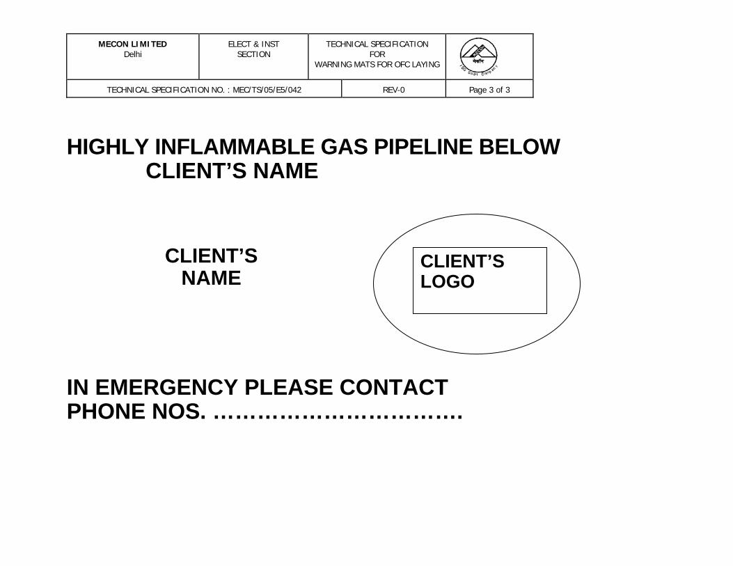
MECON LIMITED Delhi
ELECT & INST SECTION
TECHNICAL SPECIFICATION FOR
WARNING MATS FOR OFC LAYING
TECHNICAL SPECIFICATION NO. : MEC/TS/05/E5/042 REV-0 Page 3 of 3
HIGHLY INFLAMMABLE GAS PIPELINE BELOW
CLIENT’S NAME
CLIENT’SLOGO
CLIENT’S NAME
IN EMERGENCY PLEASE CONTACT PHONE NOS. …………………………….