Vol 6 Tab 1 Catalog Pages - PLATT ELECTRIC SUPPLY · V6-T1-80 Volume 6—Solid-State Motor Control...
16
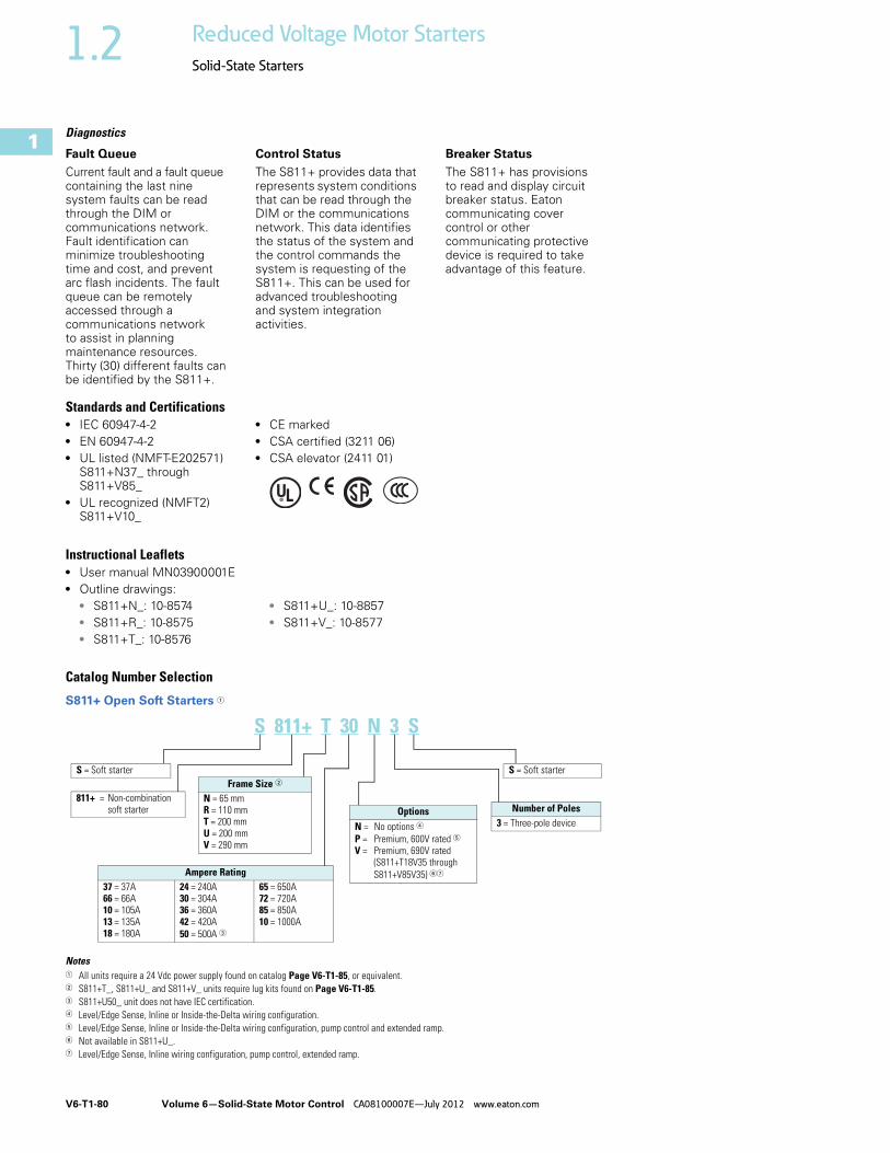
V6-T1-80 Volume 6—Solid-State Motor Control CA08100007E—July 2012 www.eaton.com 1 1 1 1 1 1 1 1 1 1 1 1 1 1 1 1 1 1 1 1 1 1 1 1 1 1 1 1 1 1 1.2 Reduced Voltage Motor Starters Solid-State Starters Diagnostics Fault Queue Current fault and a fault queue containing the last nine system faults can be read through the DIM or communications network. Fault identification can minimize troubleshooting time and cost, and prevent arc flash incidents. The fault queue can be remotely accessed through a communications network to assist in planning maintenance resources. Thirty (30) different faults can be identified by the S811+. Control Status The S811+ provides data that represents system conditions that can be read through the DIM or the communications network. This data identifies the status of the system and the control commands the system is requesting of the S811+. This can be used for advanced troubleshooting and system integration activities. Breaker Status The S811+ has provisions to read and display circuit breaker status. Eaton communicating cover control or other communicating protective device is required to take advantage of this feature. Standards and Certifications ● IEC 60947-4-2 ● EN 60947-4-2 ● UL listed (NMFT-E202571) S811+N37_ through S811+V85_ ● UL recognized (NMFT2) S811+V10_ ● CE marked ● CSA certified (3211 06) ● CSA elevator (2411 01) Instructional Leaflets ● User manual MN03900001E ● Outline drawings: ● S811+N_: 10-8574 ● S811+R_: 10-8575 ● S811+T_: 10-8576 ● S811+U_: 10-8857 ● S811+V_: 10-8577 Catalog Number Selection S811+ Open Soft Starters 1 Notes 1 All units require a 24 Vdc power supply found on catalog Page V6-T1-85, or equivalent. 2 S811+T_, S811+U_ and S811+V_ units require lug kits found on Page V6-T1-85. 3 S811+U50_ unit does not have IEC certification. 4 Level/Edge Sense, Inline or Inside-the-Delta wiring configuration. 5 Level/Edge Sense, Inline or Inside-the-Delta wiring configuration, pump control and extended ramp. 6 Not available in S811+U_. 7 Level/Edge Sense, Inline wiring configuration, pump control, extended ramp. S 811+ T 30 N 3 S Frame Size 2 N = 65 mm R = 110 mm T = 200 mm U = 200 mm V = 290 mm Ampere Rating 37 = 37A 66 = 66A 10 = 105A 13 = 135A 18 = 180A 24 = 240A 30 = 304A 36 = 360A 42 = 420A 50 = 500A 3 65 = 650A 72 = 720A 85 = 850A 10 = 1000A S = Soft starter Number of Poles 3 = Three-pole device Options N = No options 4 P = Premium, 600V rated 5 V = Premium, 690V rated (S811+T18V35 through S811+V85V35) 67 S = Soft starter 811+ = Non-combination soft starter
Transcript of Vol 6 Tab 1 Catalog Pages - PLATT ELECTRIC SUPPLY · V6-T1-80 Volume 6—Solid-State Motor Control...
V6-T1-80 Volume 6—Solid-State Motor Control CA08100007E—July 2012 www.eaton.com
1
1
1
1
1
1
1
1
1
1
1
1
1
1
1
1
1
1
1
1
1
1
1
1
1
1
1
1
1
1
1.2 Reduced Voltage Motor Starters
Solid-State Starters
Diagnostics
Fault QueueCurrent fault and a fault queue containing the last nine system faults can be read through the DIM or communications network. Fault identification can minimize troubleshooting time and cost, and prevent arc flash incidents. The fault queue can be remotely accessed through a communications network to assist in planning maintenance resources. Thirty (30) different faults can be identified by the S811+.
Control StatusThe S811+ provides data that represents system conditions that can be read through the DIM or the communications network. This data identifies the status of the system and the control commands the system is requesting of the S811+. This can be used for advanced troubleshooting and system integration activities.
Breaker StatusThe S811+ has provisions to read and display circuit breaker status. Eaton communicating cover control or other communicating protective device is required to take advantage of this feature.
Standards and Certifications ● IEC 60947-4-2● EN 60947-4-2● UL listed (NMFT-E202571)
S811+N37_ through S811+V85_
● UL recognized (NMFT2)S811+V10_
● CE marked● CSA certified (3211 06)● CSA elevator (2411 01)
Instructional Leaflets● User manual MN03900001E● Outline drawings:
● S811+N_: 10-8574● S811+R_: 10-8575● S811+T_: 10-8576
● S811+U_: 10-8857● S811+V_: 10-8577
Catalog Number Selection
S811+ Open Soft Starters 1
Notes1 All units require a 24 Vdc power supply found on catalog Page V6-T1-85, or equivalent.2 S811+T_, S811+U_ and S811+V_ units require lug kits found on Page V6-T1-85.3 S811+U50_ unit does not have IEC certification. 4 Level/Edge Sense, Inline or Inside-the-Delta wiring configuration.5 Level/Edge Sense, Inline or Inside-the-Delta wiring configuration, pump control and extended ramp.6 Not available in S811+U_.7 Level/Edge Sense, Inline wiring configuration, pump control, extended ramp.
S 811+ T 30 N 3 S
Frame Size 2
N = 65 mmR = 110 mmT = 200 mmU = 200 mmV = 290 mm
Ampere Rating37 = 37A66 = 66A10 = 105A13 = 135A18 = 180A
24 = 240A30 = 304A36 = 360A42 = 420A
50 = 500A 3
65 = 650A72 = 720A85 = 850A10 = 1000A
S = Soft starter
Number of Poles3 = Three-pole device
OptionsN = No options 4
P = Premium, 600V rated 5
V = Premium, 690V rated(S811+T18V35 through
S811+V85V35) 67
S = Soft starter
811+ = Non-combination soft starter

Volume 6—Solid-State Motor Control CA08100007E—July 2012 www.eaton.com V6-T1-81
1
1
1
1
1
1
1
1
1
1
1
1
1
1
1
1
1
1
1
1
1
1
1
1
1
1
1
1
1
1
1.2Reduced Voltage Motor Starters
Solid-State Starters
Product Selection
Standard Duty Ratings
Motor applications and customer needs come in many different varieties. With the standard and severe duty rating tables, we have attempted to provide
guidelines on what the soft starter is capable of. If the application falls under these categories, you can use these charts. For other applications, or when a
question arises, consult with your local Eaton representative or call our Technical Resource Center.
Standard Duty—15 Second Ramp, 300% Current Limit at 40°C, Inline Connection
Notes1 690V is available only from S811+T18V3S through S811+V85V3S. Not available on S811+U…V3S.2 S811+U5O_ rating does not have IEC certification.
Starting MethodRamp Current % of FLA
Ramp Time Seconds Starts per Hour
Ambient Temperature
Soft start 300% 30 sec. 3 50°C
Full voltage 500% 10 sec. 3 50°C
Wye-delta 350% 20 sec. 3 50°C
80% RVAT 480% 20 sec. 2 50°C
65% RVAT 390% 20 sec. 3 50°C
50% RVAT 300% 20 sec. 4 50°C
Max.Current
Three-Phase Motors
CatalogNumber
kW Rating (50 Hz) hp Rating (60 Hz)
230V 380–400V 440V200V 230V 460V 575–690V 1
1.0SF 1.15SF 1.0SF 1.15SF 1.0SF 1.15SF 1.0SF 1.15SF
Frame Size N
37 10 18.5 18.5 10 10 10 10 25 20 30 30 S811+N37N3S
66 18.5 30 37 20 15 20 20 50 40 60 50 S811+N66N3S
Frame Size R
105 30 55 59 30 25 40 30 75 60 100 75 S811+R10N3S
135 40 63 80 40 30 50 40 100 75 125 100 S811+R13N3S
Frame Size T
180 51 90 110 60 50 60 60 150 125 150 150 S811+T18N3S
240 75 110 147 75 60 75 75 200 150 200 200 S811+T24N3S
304 90 160 185 100 75 100 100 250 200 300 250 S811+T30N3S
Frame Size U
360 110 185 220 125 100 150 125 300 250 350 300 S811+U36N3S
420 129 220 257 150 125 175 150 350 300 450 350 S811+U42N3S
500 150 257 300 150 150 200 150 400 350 500 450 S811+U50N3S 2
Frame Size V
360 110 185 220 125 100 150 125 300 250 350 300 S811+V36N3S
420 129 220 257 150 125 175 150 350 300 450 350 S811+V42N3S
500 150 257 300 150 150 200 150 400 350 500 450 S811+V50N3S
650 200 355 425 250 200 250 200 500 450 600 500 S811+V65N3S
720 220 400 450 — — 300 250 600 500 700 600 S811+V72N3S
850 257 475 500 — — 350 300 700 600 900 700 S811+V85N3S
1000 277 525 550 — — 400 350 800 700 900 800 S811+V10N3S
S811+

V6-T1-82 Volume 6—Solid-State Motor Control CA08100007E—July 2012 www.eaton.com
1
1
1
1
1
1
1
1
1
1
1
1
1
1
1
1
1
1
1
1
1
1
1
1
1
1
1
1
1
1
1.2 Reduced Voltage Motor Starters
Solid-State Starters
Severe Duty
Severe Duty Ratings
Severe duty ratings are defined as any combination of parameters that exceed the standard duty ratings where
the ramp time is over 30 seconds, and/or the number of starts per hour exceeds 4, and/or the current limit set is
over 300%. Example: 35-second ramp, 5 starts per hour, 350% current limit at 40°C ambient.
Severe Duty—30 Second Ramp and/or 450% Current Limit at 50°C, Inline Connection
Note1 690V is available only from S811+T18V3S through S811+V85V3S. Not available on S811+U…V3S.
Starting MethodRamp Current % of FLA
Ramp Time Seconds Starts per Hour
Ambient Temperature
Soft start 450% 30 sec. 4 50°C
Full voltage 500% 10 sec. 10 50°C
Wye-delta 350% 65 sec. 3 50°C
80% RVAT 480% 25 sec. 4 50°C
65% RVAT 390% 40 sec. 4 50°C
50% RVAT 300% 60 sec. 4 50°C
Max.Current
Three-Phase Motors
CatalogNumber
kW Rating (50 Hz) hp Rating (60 Hz)
230V 380–400V 440V200V 230V 460V 575–690V 1
1.0SF 1.15SF 1.0SF 1.15SF 1.0SF 1.15SF 1.0SF 1.15SF
Frame Size N
22 5.5 10 11 5 5 7-1/2 5 15 10 20 15 S811+N37N3S
42 11 18.5 22 10 10 15 10 30 25 40 30 S811+N66N3S
Frame Size R
65 15 30 33 15 15 20 15 50 40 50 50 S811+R10N3S
80 22 40 45 25 20 30 25 60 50 75 60 S811+R13N3S
Frame Size T
115 33 59 63 30 30 40 30 75 75 100 100 S811+T18N3S
150 45 80 90 50 40 50 50 100 100 150 125 S811+T24N3S
192 55 100 110 60 50 75 60 150 125 200 150 S811+T30N3S
Frame Size U
240 75 110 147 75 60 75 75 200 150 200 200 S811+U36N3S
305 90 160 185 100 75 100 100 250 200 300 250 S811+U42N3S
Frame Size V
240 75 110 147 75 60 75 75 200 150 200 200 S811+V36N3S
305 90 160 185 100 75 100 100 250 200 300 250 S811+V42N3S
365 110 185 220 125 100 150 125 300 250 350 300 S811+V50N3S
420 129 220 257 150 125 150 150 350 300 450 350 S811+V65N3S
480 147 257 295 150 150 200 150 400 350 500 450 S811+V72N3S
525 160 280 335 150 150 200 150 450 350 500 450 S811+V85N3S
575 172 303 370 200 150 250 200 500 450 600 500 S811+V10N3S
S811+
Volume 6—Solid-State Motor Control CA08100007E—July 2012 www.eaton.com V6-T1-83
1
1
1
1
1
1
1
1
1
1
1
1
1
1
1
1
1
1
1
1
1
1
1
1
1
1
1
1
1
1
1.2Reduced Voltage Motor Starters
Solid-State Starters
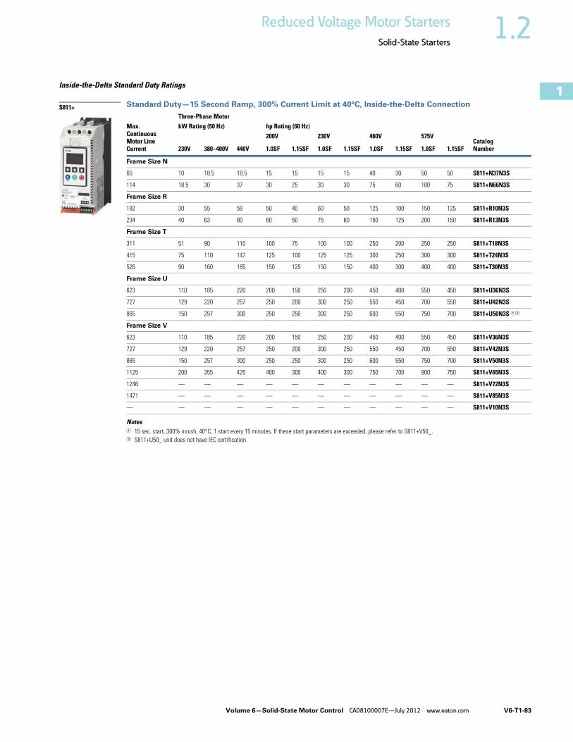
Inside-the-Delta Standard Duty Ratings
Standard Duty—15 Second Ramp, 300% Current Limit at 40°C, Inside-the-Delta Connection
Notes1 15 sec. start, 300% inrush, 40°C, 1 start every 15 minutes. If these start parameters are exceeded, please refer to S811+V50_.2 S811+U50_ unit does not have IEC certification.
Max.ContinuousMotor LineCurrent
Three-Phase Motor
CatalogNumber
kW Rating (50 Hz) hp Rating (60 Hz)
230V 380–400V 440V
200V 230V 460V 575V
1.0SF 1.15SF 1.0SF 1.15SF 1.0SF 1.15SF 1.0SF 1.15SF
Frame Size N
65 10 18.5 18.5 15 15 15 15 40 30 50 50 S811+N37N3S
114 18.5 30 37 30 25 30 30 75 60 100 75 S811+N66N3S
Frame Size R
182 30 55 59 50 40 60 50 125 100 150 125 S811+R10N3S
234 40 63 80 60 50 75 60 150 125 200 150 S811+R13N3S
Frame Size T
311 51 90 110 100 75 100 100 250 200 250 250 S811+T18N3S
415 75 110 147 125 100 125 125 300 250 300 300 S811+T24N3S
526 90 160 185 150 125 150 150 400 300 400 400 S811+T30N3S
Frame Size U
623 110 185 220 200 150 250 200 450 400 550 450 S811+U36N3S
727 129 220 257 250 200 300 250 550 450 700 550 S811+U42N3S
865 150 257 300 250 250 300 250 600 550 750 700 S811+U50N3S 12
Frame Size V
623 110 185 220 200 150 250 200 450 400 550 450 S811+V36N3S
727 129 220 257 250 200 300 250 550 450 700 550 S811+V42N3S
865 150 257 300 250 250 300 250 600 550 750 700 S811+V50N3S
1125 200 355 425 400 300 400 300 750 700 900 750 S811+V65N3S
1246 — — — — — — — — — — — S811+V72N3S
1471 — — — — — — — — — — — S811+V85N3S
— — — — — — — — — — — — S811+V10N3S
S811+

V6-T1-84 Volume 6—Solid-State Motor Control CA08100007E—July 2012 www.eaton.com
1
1
1
1
1
1
1
1
1
1
1
1
1
1
1
1
1
1
1
1
1
1
1
1
1
1
1
1
1
1
1.2 Reduced Voltage Motor Starters
Solid-State Starters
Inside-the-Delta Severe Duty RatingsSevere duty ratings are defined as any combination of parameters that exceed the standard duty ratings where the ramp time is over 30 seconds, and/or the number of starts per hour exceeds 4, and/or the current limit set is over 300%.
Example: 35-second ramp, 5 starts per hour 350% current limit at 40°C ambient.
Severe Duty—30 Second Ramp and/or 450% Current Limit at 50°C, Inside-the-Delta Connection
Note1 S811+U50_ unit does not have IEC certification.
Max.ContinuousMotor LineCurrent
Three-Phase Motor
CatalogNumber
kW Rating (50 Hz) hp Rating (60 Hz)
230V 380–400V 440V
200V 230V 460V 575V
1.0SF 1.15SF 1.0SF 1.15SF 1.0SF 1.15SF 1.0SF 1.15SF
Frame Size N
39 5.5 10 11 7-1/2 7-1/2 10 7-1/2 25 15 30 25 S811+N37N3S
73 11 18.5 22 15 15 25 15 50 40 60 50 S811+N66N3S
Frame Size R
111 15 30 33 25 25 30 25 75 60 75 75 S811+R10N3S
138 22 40 45 40 30 50 40 100 75 120 100 S811+R13N3S
Frame Size T
199 33 59 63 50 50 60 50 125 125 150 150 S811+T18N3S
257 45 80 90 75 60 75 75 150 150 250 200 S811+T24N3S
324 55 100 110 100 75 100 100 250 200 300 250 S811+T30N3S
Frame Size U
415 75 110 147 125 100 125 125 300 250 300 300 S811+U36N3S
526 90 160 185 150 120 150 150 400 300 450 400 S811+U42N3S
623 110 185 220 200 150 250 200 450 400 550 450 S811+U50N3S 1
Frame Size V
415 75 110 147 125 100 125 125 300 250 300 300 S811+V36N3S
526 90 160 185 150 120 150 150 400 300 450 400 S811+V42N3S
623 110 185 220 200 150 250 200 450 400 550 450 S811+V50N3S
727 129 220 257 250 200 250 250 550 450 700 550 S811+V65N3S
816 147 257 295 250 250 300 250 600 550 750 700 S811+V72N3S
908 160 280 335 250 250 300 250 700 550 750 700 S811+V85N3S
— — — — — — — — — — — — S811+V10N3S
S811+

Volume 6—Solid-State Motor Control CA08100007E—July 2012 www.eaton.com V6-T1-85
1
1
1
1
1
1
1
1
1
1
1
1
1
1
1
1
1
1
1
1
1
1
1
1
1
1
1
1
1
1
1.2Reduced Voltage Motor Starters
Solid-State Starters
Accessories
Lug Kits S811+T_, S811U_ and S811+V_ soft starters each have different lug options based on your wiring needs. Each lug kit contains three lugs that can be mounted on either the load or line side.
Lug Kits
Power Supplies24 Vdc power supply that can be used with the S811+ SSRV or as a stand-alone device.
Power Supplies
Lug Cover Kits Replacement covers for the S811+T_, S811+U_ and S811+V_ soft starters are available in case of damage to the existing covers.
Lug Cover Kits
IP20 Kits
IP20 Kits
Surge SuppressorsThe surge suppressor can mount on either the line or load side of the soft starter. It is designed to clip the line voltage (or load side induced voltage).
Surge Suppressors
Notes1 The EML33 does not have a CSA listing. 2 S811+T_ only.
S811+Catalog Number Description
KitsRequired
CatalogNumber
S811+T_,S811+U_
2 cable connections, 4 AWG to 1/0 cable 2 EML22
1 cable connection, 4/0 to 500 kcmil cable EML23
2 cable connections, 4/0 to 500 kcmil cable EML24
1 cable connection, 2/0 to 300 kcmil cable EML25
2 cable connections, 2/0 to 300 kcmil cable EML26
S811+V_ 2 cable connections, 4/0 to 500 kcmil cable 2 EML28
4 cable connections, 4/0 to 500 kcmil cable EML30
6 cable connections, 4/0 to 500 kcmil cable EML32
4 cable connections, 2/0 to 300 kcmil cable EML33 1
Lug Kit
DescriptionCatalogNumber
85–264 Vac input24 Vdc output
PSG240E
360–575 Vac input24 Vdc output
PSG240F
DescriptionCatalogNumber
Lug cover S811+T_, S811+U_ EML27
Lug cover S811+V_ EML34
DescriptionCatalogNumber
S811+N_ SS-IP20-N
S811+R_ SS-IP20-R
S811+T_ and S811+U_ SS-IP20-TU
S811+V_ SS-IP20-V
DescriptionCatalogNumber
600V MOV for S811+_ units EMS39
690V MOV for S811+_ units 2 EMS41
Surge Suppressor
V6-T1-86 Volume 6—Solid-State Motor Control CA08100007E—July 2012 www.eaton.com
1
1
1
1
1
1
1
1
1
1
1
1
1
1
1
1
1
1
1
1
1
1
1
1
1
1
1
1
1
1
1.2 Reduced Voltage Motor Starters
Solid-State Starters
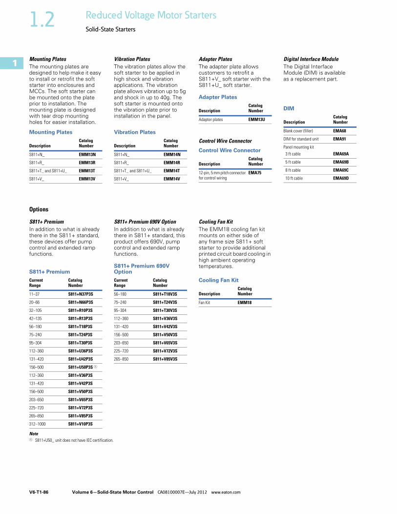
Mounting PlatesThe mounting plates are designed to help make it easy to install or retrofit the soft starter into enclosures and MCCs. The soft starter can be mounted onto the plate prior to installation. The mounting plate is designed with tear drop mounting holes for easier installation.
Mounting Plates
Vibration PlatesThe vibration plates allow the soft starter to be applied in high shock and vibration applications. The vibration plate allows vibration up to 5g and shock in up to 40g. The soft starter is mounted onto the vibration plate prior to installation in the panel.
Vibration Plates
Adapter PlatesThe adapter plate allows customers to retrofit a S811+V_ soft starter with the S811+U_ soft starter.
Adapter Plates
Control Wire Connector
Control Wire Connector
Digital Interface ModuleThe Digital Interface Module (DIM) is available as a replacement part.
DIM
Options
S811+ PremiumIn addition to what is already there in the S811+ standard, these devices offer pump control and extended ramp functions.
S811+ Premium
S811+ Premium 690V OptionIn addition to what is already there in S811+ standard, this product offers 690V, pump control and extended ramp functions.
S811+ Premium 690V Option
Cooling Fan KitThe EMM18 cooling fan kit mounts on either side of any frame size S811+ soft starter to provide additional printed circuit board cooling in high ambient operating temperatures.
Cooling Fan Kit
Note1 S811+U50_ unit does not have IEC certification.
DescriptionCatalogNumber
S811+N_ EMM13N
S811+R_ EMM13R
S811+T_ and S811+U_ EMM13T
S811+V_ EMM13V
DescriptionCatalogNumber
S811+N_ EMM14N
S811+R_ EMM14R
S811+T_ and S811+U_ EMM14T
S811+V_ EMM14V
DescriptionCatalogNumber
Adapter plates EMM13U
DescriptionCatalogNumber
12-pin, 5 mm pitch connector for control wiring
EMA75
DescriptionCatalogNumber
Blank cover (filler) EMA68
DIM for standard unit EMA91
Panel mounting kit
3 ft cable EMA69A
5 ft cable EMA69B
8 ft cable EMA69C
10 ft cable EMA69D
CurrentRange
Catalog Number
11–37 S811+N37P3S
20–66 S811+N66P3S
32–105 S811+R10P3S
42–135 S811+R13P3S
56–180 S811+T18P3S
75–240 S811+T24P3S
95–304 S811+T30P3S
112–360 S811+U36P3S
131–420 S811+U42P3S
156–500 S811+U50P3S 1
112–360 S811+V36P3S
131–420 S811+V42P3S
156–500 S811+V50P3S
203–650 S811+V65P3S
225–720 S811+V72P3S
265–850 S811+V85P3S
312–1000 S811+V10P3S
CurrentRange
Catalog Number
56–180 S811+T18V3S
75–240 S811+T24V3S
95–304 S811+T30V3S
112–360 S811+V36V3S
131–420 S811+V42V3S
156–500 S811+V50V3S
203–650 S811+V65V3S
225–720 S811+V72V3S
265–850 S811+V85V3S
DescriptionCatalogNumber
Fan Kit EMM18

Volume 6—Solid-State Motor Control CA08100007E—July 2012 www.eaton.com V6-T1-87
1
1
1
1
1
1
1
1
1
1
1
1
1
1
1
1
1
1
1
1
1
1
1
1
1
1
1
1
1
1
1.2Reduced Voltage Motor Starters
Solid-State Starters
Technical Data and Specifications
Soft Starters—S811+ Description S811+N37_ S811+N66_ S811+R10+ S811+R13_
Max. current capacity 37 66 105 135
FLA range 11–37 20–66 32–105 42–135
General Information
Bypass mechanical lifespan 10M 10M 10M 10M
Insulating voltage Ui 660V 660V 660V 660V
Ramp time range 0.5–180 seconds (0.5–360 seconds S811+ Premium)
0.5–180 seconds (0.5–360 seconds S811+ Premium)
0.5–180 seconds (0.5–360 seconds S811+ Premium)
0.5–180 seconds (0.5–360 seconds S811+ Premium)
Resistance to vibration 3g 3g 3g 3g
Resistance to shock 15g 15g 15g 15g
Electrical Information
Operating voltage 200–600V 200–600V 200–600V 200–600V
Operating frequency 47–63 Hz 47–63 Hz 47–63 Hz 47–63 Hz
Overload setting 30–100% 30–100% 30–100% 30–100%
Trip class 5, 10, 20 and 30 5, 10, 20 and 30 5, 10, 20 and 30 5, 10, 20 and 30
Cabling Capacity (IEC 947)
Number of conductors 1 1 1 1
Wire sizes 14–2 14–2 14–4/0 14–4/0
Type of connectors Box lug Box lug Box lug Box lug
Control Wiring (12-Pin)
Wire sizes in AWG 22–14 22–14 22–14 22–14
Number of conductors (stranded) 2 (or one AWG 12) 2 (or one AWG 12) 2 (or one AWG 12) 2 (or one AWG 12)
Torque requirements in lb-in 3.5 3.5 3.5 3.5
Solid, stranded or flexible max. size in mm2 3.31 3.31 3.31 3.31
Control Power Requirements
Voltage range (24V ±10%) 21.6–26.4 21.6–26.4 21.6–26.4 21.6–26.4
Steady-state current amps 1.0 1.0 1.0 1.0
Inrush current amps 10 10 10 10
Ripple 1% 1% 1% 1%
Relays (1) Class A and C
Voltage AC—maximum 240 240 240 240
Voltage DC—maximum 120 120 120 120
Amps—maximum 3 3 3 3
Environment
Temperature—operating –30 to 50°C (no derating) consult factory for operation >50°C
–30 to 50°C (no derating) consult factory for operation >50°C
–30 to 50°C (no derating) consult factory for operation >50°C
–30 to 50°C (no derating) consult factory for operation >50°C
Temperature—storage –50 to 70°C –50 to 70°C –50 to 70°C –50 to 70°C
Altitude <2000m—consult factory for operation >2000m
<2000m—consult factory for operation >2000m
<2000m—consult factory for operation >2000m
<2000m—consult factory for operation >2000m
Humidity <95% noncondensing <95% noncondensing <95% noncondensing <95% noncondensing
Operating position Any Any Any Any
Pollution degree IEC947-1 3 3 3 3
Impulse withstand voltage IEC947-4-1 6000V 6000V 6000V 6000V

V6-T1-88 Volume 6—Solid-State Motor Control CA08100007E—July 2012 www.eaton.com
1
1
1
1
1
1
1
1
1
1
1
1
1
1
1
1
1
1
1
1
1
1
1
1
1
1
1
1
1
1
1.2 Reduced Voltage Motor Starters
Solid-State Starters
Soft Starters—S811+, continued Description S811+T18_ S811+T24_ S811+T30_ S811+U36_
Max. current capacity 180 240 304 360
FLA range 56–180 75–240 95–304 112–360
General Information
Bypass mechanical lifespan 10M 10M 10M 10M
Insulating voltage Ui 660V 660V 660V 660V
Ramp time range 0.5–180 seconds (0.5–360 seconds S811+ Premium)
0.5–180 seconds (0.5–360 seconds S811+ Premium)
0.5–180 seconds (0.5–360 seconds S811+ Premium)
0.5–180 seconds (0.5–360 seconds S811+ Premium)
Resistance to vibration 3g 3g 3g 3g
Resistance to shock 15g 15g 15g 15g
Electrical Information
Operating voltage 200–600V 200–600V 200–600V 200–600V
Operating frequency 47–63 Hz 47–63 Hz 47–63 Hz 47–63 Hz
Overload setting 30–100% 30–100% 30–100% 30–100%
Trip class 5, 10, 20 and 30 5, 10, 20 and 30 5, 10, 20 and 30 5, 10, 20 and 30
Cabling Capacity (IEC 947)
Number of conductors 1 or 2 1 or 2 1 or 2 1 or 2
Wire sizes 4 AWG to 500 kcmil 4 AWG to 500 kcmil 4 AWG to 500 kcmil 4 AWG to 500 kcmil
Type of connectors Add-on lug kit Add-on lug kit Add-on lug kit Add-on lug kit
Control Wiring (12-Pin)
Wire sizes in AWG 22–14 22–14 22–14 22–14
Number of conductors (stranded) 2 (or one AWG 12) 2 (or one AWG 12) 2 (or one AWG 12) 2 (or one AWG 12)
Torque requirements in lb-in 3.5 3.5 3.5 3.5
Solid, stranded or flexible max. size in mm2 3.31 3.31 3.31 3.31
Control Power Requirements
Voltage range (24V ±10%) 21.6–26.4 21.6–26.4 21.6–26.4 21.6–26.4
Steady-state current amps 1.0 1.0 1.0 1.0
Inrush current amps 10 10 10 10
Ripple 1% 1% 1% 1%
Relays (1) Class A and C
Voltage AC—maximum 240 240 240 240
Voltage DC—maximum 120 120 120 120
Amps—maximum 3 3 3 3
Environment
Temperature—operating –30 to 50°C (no derating) consult factory for operation >50°C
–30 to 50°C (no derating) consult factory for operation >50°C
–30 to 50°C (no derating) consult factory for operation >50°C
–30 to 50°C (no derating) consult factory for operation >50°C
Temperature—storage –50 to 70°C –50 to 70°C –50 to 70°C –50 to 70°C
Altitude <2000m—consult factory for operation >2000m
<2000m—consult factory for operation >2000m
<2000m—consult factory for operation >2000m
<2000m—consult factory for operation >2000m
Humidity <95% noncondensing <95% noncondensing <95% noncondensing <95% noncondensing
Operating position Any Any Any Any
Pollution degree IEC947-1 3 3 3 3
Impulse withstand voltage IEC947-4-1 6000V 6000V 6000V 6000V

Volume 6—Solid-State Motor Control CA08100007E—July 2012 www.eaton.com V6-T1-89
1
1
1
1
1
1
1
1
1
1
1
1
1
1
1
1
1
1
1
1
1
1
1
1
1
1
1
1
1
1
1.2Reduced Voltage Motor Starters
Solid-State Starters
Soft Starters—S811+, continued
Note1 S811+U50_ unit does not have IEC certification.
Description S811+U42_ S811+U50_ 1 S811+V36_ S811+V42_
Max. current capacity 420 500 360 420
FLA range 131–420 156–500 112–360 131–420
General Information
Bypass mechanical lifespan 10M 10M 10M 10M
Insulating voltage Ui 660V 660V 660V 660V
Ramp time range 0.5–180 seconds (0.5–360 seconds S811+ Premium)
0.5–180 seconds (0.5–360 seconds S811+ Premium)
0.5–180 seconds (0.5–360 seconds S811+ Premium)
0.5–180 seconds (0.5–360 seconds S811+ Premium)
Resistance to vibration 3g 3g 3g 3g
Resistance to shock 15g 15g 15g 15g
Electrical Information
Operating voltage 200–600V 200–600V 200–600V 200–600V
Operating frequency 47–63 Hz 47–63 Hz 47–63 Hz 47–63 Hz
Overload setting 30–100% 30–100% 30–100% 30–100%
Trip class 5, 10, 20 and 30 5, 10, 20 and 30 5, 10, 20 and 30 5, 10, 20 and 30
Cabling Capacity (IEC 947)
Number of conductors 1 or 2 1 or 2 2, 4 or 6 2, 4 or 6
Wire sizes 4 AWG to 500 kcmil 4 AWG to 500 kcmil 4 AWG to 500 kcmil 4 AWG to 500 kcmil
Type of connectors Add-on lug kit Add-on lug kit Add-on lug kit Add-on lug kit
Control Wiring (12-Pin)
Wire sizes in AWG 22–14 22–14 22–14 22–14
Number of conductors (stranded) 2 (or one AWG 12) 2 (or one AWG 12) 2 (or one AWG 12) 2 (or one AWG 12)
Torque requirements in lb-in 3.5 3.5 3.5 3.5
Solid, stranded or flexible max. size in mm2 3.31 3.31 3.31 3.31
Control Power Requirements
Voltage range (24V ±10%) 21.6–26.4 21.6–26.4 21.6–26.4 21.6–26.4
Steady-state current amps 1.0 1.0 1.4 1.4
Inrush current amps 10 10 10 10
Ripple 1% 1% 1% 1%
Relays (1) Class A and C
Voltage AC—maximum 240 240 240 240
Voltage DC—maximum 120 120 120 120
Amps—maximum 3 3 3 3
Environment
Temperature—operating –30 to 50°C (no derating) consult factory for operation >50°C
–30 to 50°C (no derating) consult factory for operation >50°C
–30 to 50°C (no derating) consult factory for operation >50°C
–30 to 50°C (no derating) consult factory for operation >50°C
Temperature—storage –50 to 70°C –50 to 70°C –50 to 70°C –50 to 70°C
Altitude <2000m—consult factory for operation >2000m
<2000m—consult factory for operation >2000m
<2000m—consult factory for operation >2000m
<2000m—consult factory for operation >2000m
Humidity <95% noncondensing <95% noncondensing <95% noncondensing <95% noncondensing
Operating position Any Any Any Any
Pollution degree IEC947-1 3 3 3 3
Impulse withstand voltage IEC947-4-1 6000V 6000V 6000V 6000V
V6-T1-90 Volume 6—Solid-State Motor Control CA08100007E—July 2012 www.eaton.com
1
1
1
1
1
1
1
1
1
1
1
1
1
1
1
1
1
1
1
1
1
1
1
1
1
1
1
1
1
1
1.2 Reduced Voltage Motor Starters
Solid-State Starters
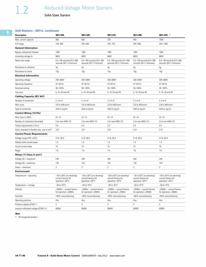
Soft Starters—S811+, continued
Note1 UR recognized product.
Description S811+V50_ S811+V65_ S811+V72_ S811+V85_ S811+V10_ 1
Max. current capacity 500 650 720 850 1000
FLA range 156–500 203–650 225–720 265–580 320–1000
General Information
Bypass mechanical lifespan 10M 10M 10M 10M 10M
Insulating voltage Ui 660V 660V 660V 660V 660V
Ramp time range 0.5–180 seconds (0.5–360 seconds S811+ Premium)
0.5–180 seconds (0.5–360 seconds S811+ Premium)
0.5–180 seconds (0.5–360 seconds S811+ Premium)
0.5–180 seconds (0.5–360 seconds S811+ Premium)
0.5–180 seconds (0.5–360 seconds S811+ Premium)
Resistance to vibration 3g 3g 3g 3g 3g
Resistance to shock 15g 15g 15g 15g 15g
Electrical Information
Operating voltage 200–600V 200–600V 200–600V 200–600V 200–600V
Operating frequency 47–63 Hz 47–63 Hz 47–63 Hz 47–63 Hz 47–63 Hz
Overload setting 30–100% 30–100% 30–100% 30–100% 30–100%
Trip class 5, 10, 20 and 30 5, 10, 20 and 30 5, 10, 20 and 30 5, 10, 20 and 30 5, 10, 20 and 30
Cabling Capacity (IEC 947)
Number of conductors 2, 4 or 6 2, 4 or 6 2, 4 or 6 2, 4 or 6 2, 4 or 6
Wire sizes 2/0 to 500 kcmil 2/0 to 500 kcmil 2/0 to 500 kcmil 2/0 to 500 kcmil 2/0 to 500 kcmil
Type of connectors Add-on lug kit Add-on lug kit Add-on lug kit Add-on lug kit Add-on lug kit
Control Wiring (12-Pin)
Wire sizes in AWG 22–14 22–14 22–14 22–14 22–14
Number of conductors (stranded) 2 (or one AWG 12) 2 (or one AWG 12) 2 (or one AWG 12) 2 (or one AWG 12) 2 (or one AWG 12)
Torque requirements in lb-in 3.5 3.5 3.5 3.5 3.5
Solid, stranded or flexible max. size in mm2 3.31 3.31 3.31 3.31 3.31
Control Power Requirements
Voltage range (24V ±10%) 21.6–26.4 21.6–26.4 21.6–26.4 21.6–26.4 21.6–26.4
Steady-state current amps 1.4 1.4 1.4 1.4 1.4
Inrush current amps 10 10 10 10 10
Ripple 1% 1% 1% 1% 1%
Relays (1) Class A and C
Voltage AC—maximum 240 240 240 240 240
Voltage DC—maximum 120 120 120 120 120
Amps—maximum 3 3 3 3 3
Environment
Temperature—operating –30 to 50°C (no derating) consult factory for operation >50°C
–30 to 50°C (no derating) consult factory for operation >50°C
–30 to 50°C (no derating) consult factory for operation >50°C
–30 to 50°C (no derating) consult factory for operation >50°C
–30 to 50°C (no derating) consult factory for operation >50°C
Temperature—storage –50 to 70°C –50 to 70°C –50 to 70°C –50 to 70°C –50 to 70°C
Altitude <2000m—consult factory for operation >2000m
<2000m—consult factory for operation >2000m
<2000m—consult factory for operation >2000m
<2000m—consult factory for operation >2000m
<2000m—consult factory for operation >2000m
Humidity <95% noncondensing <95% noncondensing <95% noncondensing <95% noncondensing <95% noncondensing
Operating position Any Any Any Any Any
Pollution degree IEC947-1 3 3 3 3 3
Impulse withstand voltage IEC947-4-1 6000V 6000V 6000V 6000V 6000V

Volume 6—Solid-State Motor Control CA08100007E—July 2012 www.eaton.com V6-T1-91
1
1
1
1
1
1
1
1
1
1
1
1
1
1
1
1
1
1
1
1
1
1
1
1
1
1
1
1
1
1
1.2Reduced Voltage Motor Starters
Solid-State Starters
Wiring Diagrams
Line Connected Soft Starter
Inside-the-Delta Connected Soft Starter for a 6-Lead Motor
Inside-the-Delta Connected Soft Starter for a 12-Lead Low Voltage Motor
Inside-the-Delta Connected Soft Starter for a 12-Lead High Voltage Motor
1 L1 3 L2 5 L3
2 T1 4 T2 6 T3
3~M
L1S L2SSupply
L3S
L31L1
3L2
5L3
T5 T4 T6
T3
T3
T3
T6
T4
T1T1
T2
T2
T2
T1
2T1
4T2
6T3
S811
T5
L1
L1
Motor
L3
L2L2
L1S L2SSupply
L3S
L3
L1
1L1
3L2
5L3
T11T5
T11T10T4
T12T6
T3T9
T3
T5
T3
T6T10
T7
T4
T1
T1
T12
T9
T2T8
T2T2
T1T7
2T1
4T2
6T3
T8
L1
Motor
L3
L2L2
12-LeadLow Voltage
S811
L1S L2SSupply 12-Lead
High VoltageL3S
L3
L1
1L1
3L2
5L3
T11
T11
T10 T12
T3
T3
T3
T6T10
T7T4
T1T1
T12
T9
T2
T2
T2
T1
2T1
4T2
6T3
T8T5
T5T8
T6T9
L1
T7T4
Motor
L3
L2L2
S811
V6-T1-92 Volume 6—Solid-State Motor Control CA08100007E—July 2012 www.eaton.com
1
1
1
1
1
1
1
1
1
1
1
1
1
1
1
1
1
1
1
1
1
1
1
1
1
1
1
1
1
1
1.2 Reduced Voltage Motor Starters
Solid-State Starters
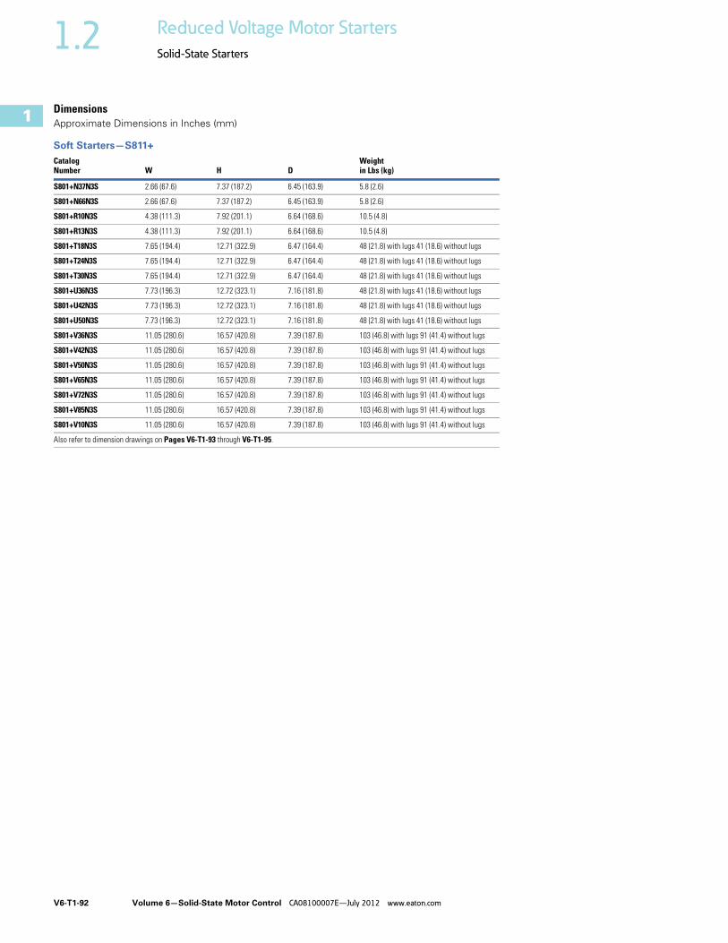
DimensionsApproximate Dimensions in Inches (mm)
Soft Starters—S811+ Catalog Number W H D
Weightin Lbs (kg)
S801+N37N3S 2.66 (67.6) 7.37 (187.2) 6.45 (163.9) 5.8 (2.6)
S801+N66N3S 2.66 (67.6) 7.37 (187.2) 6.45 (163.9) 5.8 (2.6)
S801+R10N3S 4.38 (111.3) 7.92 (201.1) 6.64 (168.6) 10.5 (4.8)
S801+R13N3S 4.38 (111.3) 7.92 (201.1) 6.64 (168.6) 10.5 (4.8)
S801+T18N3S 7.65 (194.4) 12.71 (322.9) 6.47 (164.4) 48 (21.8) with lugs 41 (18.6) without lugs
S801+T24N3S 7.65 (194.4) 12.71 (322.9) 6.47 (164.4) 48 (21.8) with lugs 41 (18.6) without lugs
S801+T30N3S 7.65 (194.4) 12.71 (322.9) 6.47 (164.4) 48 (21.8) with lugs 41 (18.6) without lugs
S801+U36N3S 7.73 (196.3) 12.72 (323.1) 7.16 (181.8) 48 (21.8) with lugs 41 (18.6) without lugs
S801+U42N3S 7.73 (196.3) 12.72 (323.1) 7.16 (181.8) 48 (21.8) with lugs 41 (18.6) without lugs
S801+U50N3S 7.73 (196.3) 12.72 (323.1) 7.16 (181.8) 48 (21.8) with lugs 41 (18.6) without lugs
S801+V36N3S 11.05 (280.6) 16.57 (420.8) 7.39 (187.8) 103 (46.8) with lugs 91 (41.4) without lugs
S801+V42N3S 11.05 (280.6) 16.57 (420.8) 7.39 (187.8) 103 (46.8) with lugs 91 (41.4) without lugs
S801+V50N3S 11.05 (280.6) 16.57 (420.8) 7.39 (187.8) 103 (46.8) with lugs 91 (41.4) without lugs
S801+V65N3S 11.05 (280.6) 16.57 (420.8) 7.39 (187.8) 103 (46.8) with lugs 91 (41.4) without lugs
S801+V72N3S 11.05 (280.6) 16.57 (420.8) 7.39 (187.8) 103 (46.8) with lugs 91 (41.4) without lugs
S801+V85N3S 11.05 (280.6) 16.57 (420.8) 7.39 (187.8) 103 (46.8) with lugs 91 (41.4) without lugs
S801+V10N3S 11.05 (280.6) 16.57 (420.8) 7.39 (187.8) 103 (46.8) with lugs 91 (41.4) without lugs
Also refer to dimension drawings on Pages V6-T1-93 through V6-T1-95.

Volume 6—Solid-State Motor Control CA08100007E—July 2012 www.eaton.com V6-T1-93
1
1
1
1
1
1
1
1
1
1
1
1
1
1
1
1
1
1
1
1
1
1
1
1
1
1
1
1
1
1
1.2Reduced Voltage Motor Starters
Solid-State Starters
Approximate Dimensions in Inches (mm)
S811+N_
S811+R_
6.87(174.5)
1.97 (50.0)
4X Ø 0.22(5.5)
7.37(187.2)
6.45 (163.9)
5.35(135.9)
5.89(149.7)
3.32(84.4)
2.66(67.6)
5.54(140.7)
4.38 (111.3)
3.54 (90.0)
4X Ø 0.27(6.8)
6.64 (168.6)
7.92(201.2)
6.08(154.5)
7.44(189.0)
3.49(88.5)

V6-T1-94 Volume 6—Solid-State Motor Control CA08100007E—July 2012 www.eaton.com
1
1
1
1
1
1
1
1
1
1
1
1
1
1
1
1
1
1
1
1
1
1
1
1
1
1
1
1
1
1
1.2 Reduced Voltage Motor Starters
Solid-State Starters
Approximate Dimensions in Inches (mm)
S811+T_
S811+U_
11.77(299.0) 12.71
(322.9)
6.47 (164.4)
7.65 (194.4)
5.40(137.3)
5.95(151.1)
5.91 (150.0)
0.28(7.1)
6X Ø
2.95(75.0)
7.16 (181.8)
6X Ø
12.72(323.1)11.77
(299.0) 6.09(154.8)
6.64(168.6)
2.60(66.0)
0.28(7.1)
5.20 (132.0)
7.73 (196.3)
Volume 6—Solid-State Motor Control CA08100007E—July 2012 www.eaton.com V6-T1-95
1
1
1
1
1
1
1
1
1
1
1
1
1
1
1
1
1
1
1
1
1
1
1
1
1
1
1
1
1
1
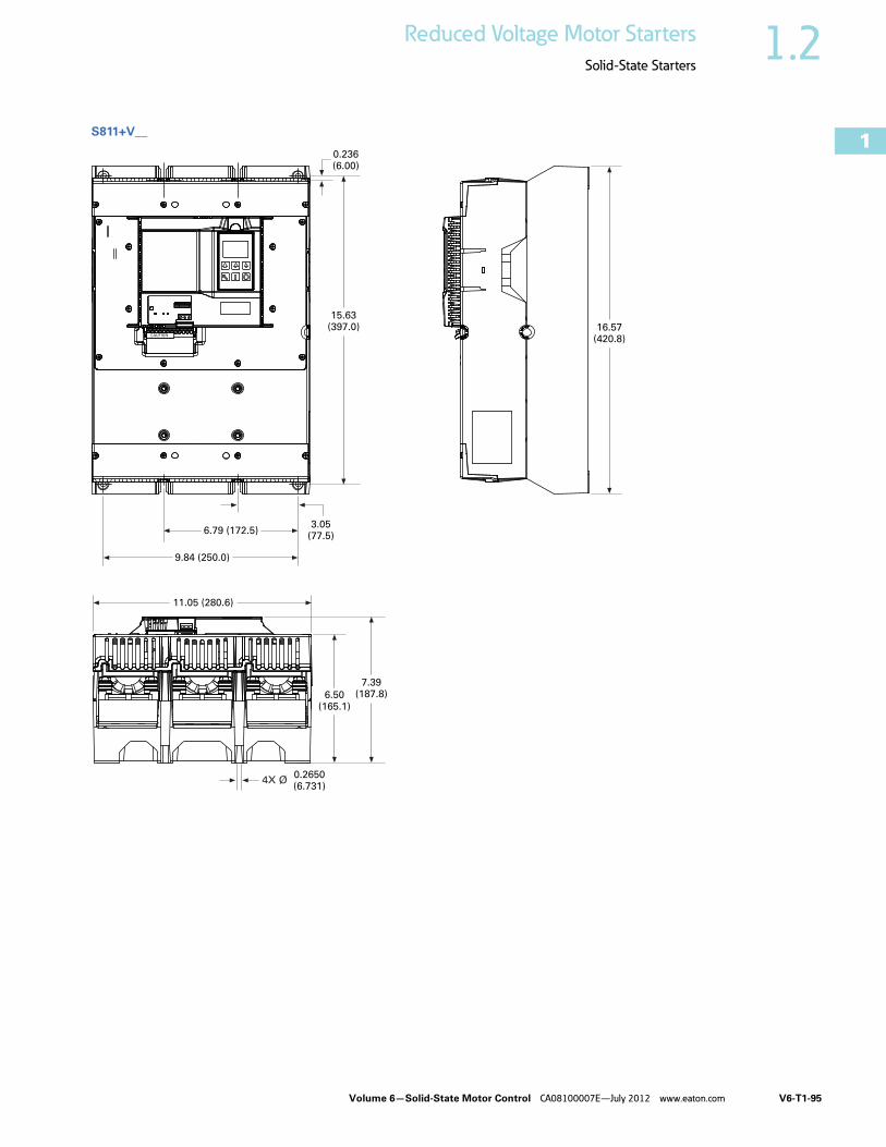
1.2Reduced Voltage Motor Starters
Solid-State Starters
S811+V__
6.79 (172.5)
0.236(6.00)
3.05(77.5)
9.84 (250.0)
15.63(397.0)
4X Ø 0.2650(6.731)
6.50(165.1)
7.39(187.8)
11.05 (280.6)
16.57(420.8)