Vogt Valves - Flow and ControlToday, Vogt Valves supports a worldwide network of distributors with...
53
Vogt Valves Catalog and Application Manual Vogt Valves VVACT0000-01 (Replaces VV200)
Transcript of Vogt Valves - Flow and ControlToday, Vogt Valves supports a worldwide network of distributors with...

Vogt Valves
Catalog and ApplicationManual
Vogt ValvesVVACT0000-01(Replaces VV200)
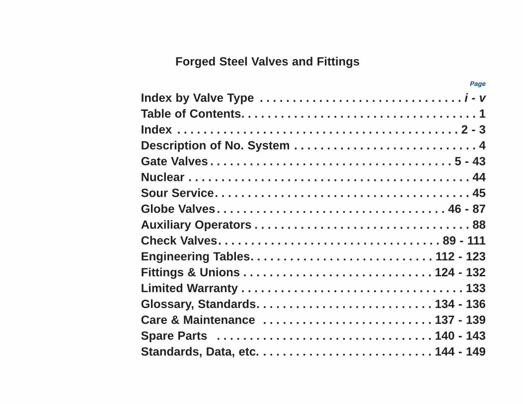
Forged Steel Valves and Fittings
Page
Index by Valve Type . . . . . . . . . . . . . . . . . . . . . . . . . . . . . . . i - vTable of Contents. . . . . . . . . . . . . . . . . . . . . . . . . . . . . . . . . . . . 1Index . . . . . . . . . . . . . . . . . . . . . . . . . . . . . . . . . . . . . . . . . . . 2 - 3Description of No. System . . . . . . . . . . . . . . . . . . . . . . . . . . . . 4Gate Valves . . . . . . . . . . . . . . . . . . . . . . . . . . . . . . . . . . . . . 5 - 43Nuclear . . . . . . . . . . . . . . . . . . . . . . . . . . . . . . . . . . . . . . . . . . . 44Sour Service. . . . . . . . . . . . . . . . . . . . . . . . . . . . . . . . . . . . . . . 45Globe Valves . . . . . . . . . . . . . . . . . . . . . . . . . . . . . . . . . . . 46 - 87Auxiliary Operators . . . . . . . . . . . . . . . . . . . . . . . . . . . . . . . . . 88Check Valves. . . . . . . . . . . . . . . . . . . . . . . . . . . . . . . . . . 89 - 111Engineering Tables. . . . . . . . . . . . . . . . . . . . . . . . . . . . 112 - 123Fittings & Unions . . . . . . . . . . . . . . . . . . . . . . . . . . . . . 124 - 132Limited Warranty . . . . . . . . . . . . . . . . . . . . . . . . . . . . . . . . . . 133Glossary, Standards. . . . . . . . . . . . . . . . . . . . . . . . . . . 134 - 136Care & Maintenance . . . . . . . . . . . . . . . . . . . . . . . . . . 137 - 139Spare Parts . . . . . . . . . . . . . . . . . . . . . . . . . . . . . . . . . 140 - 143Standards, Data, etc. . . . . . . . . . . . . . . . . . . . . . . . . . . 144 - 149

Press. Class Material Bonnet Joint End Connection Bonnet Type SERIES150 A105 Bolted Flanged OS&Y 353
Butt Weld OS&Y BW353THd/SW OS&Y See Class 800
A182 F316/F316 L Bolted Flanged OS&Y 358A350 LF2 Bolted Flanged OS&Y 32353
300 A105 Bolted Flanged OS&Y 363Butt Weld OS&Y BW363Thd/SW OS&Y See Class 800
A182 F316/F316 L Bolted Flanged OS&Y 368A350 LF2 Bolted Flanged OS&Y 32363
600 A105 Bolted Flanged OS&Y 373, 13373, 11403Butt Weld OS&Y BW373Thd/SW OS&Y See Class 800
A182 F316/F316 L Bolted Flanged OS&Y 378A350 LF2 Bolted Flanged OS&Y 32373
Threaded OS&Y 12111, 13111, 11103ISS 12161
Socket Weld OS&Y SW12111, SW13111, SW11103Bolted ISS SW12161
Male Thd x Fem Thd OS&Y TT12111Male Soc x Fem Thd OS&Y ST 12111Male Cpt x Fem Thd OS&Y CT12111
A105 Threaded OS&Y 2801, 2801BISS 2811
Socket Weld OS&Y SW2801, SW2801B Weld ISS SW2811
Male Thd x Fem Thd OS&Y TT2801ISS TT2811
Male Soc x Fem Thd OS&Y ST2801Male Cpt x Fem Thd OS&Y CT 2801, CT 2901
Union Threaded ISS 59851800 Socket Weld ISS SW59851
A350 LF2 Bolted Threaded OS&Y 32111Socket Weld OS&Y SW32111
Bolted Threaded OS&Y 12401, 13401Socket Weld OS&Y SW12401, SW13401Threaded OS&Y 2831Socket Weld OS&Y SW2831
A182 F3/F316L Weld Male Thd x Fem Thd OS&Y TT2831Male Soc x Fem Thd OS&Y ST2831Male Cpt x Fem Thd OS&Y CT2831
Union Threaded ISS 59951Socket Weld ISS SW59951
A182 F316H Bolted Threaded OS&Y 82401Socket Weld OS&Y SW82401
A182 F5 Bolted Threaded OS&Y 12421Socket Weld OS&Y SW12421
A182 F9 Bolted Threaded OS&Y 12921Socket Weld OS&Y SW12921
i
Gate Valve Index

ii
Globe Valve Index
Press. Class Material Bonnet Joint End Connection Bonnet Type SERIES800 (cont.) A182 F11, CL2 Bolted Threaded OS&Y 12321
Socket Weld OS&Y SW12321A182 F22 CL 3 Bolted Threaded OS&Y 12521
Socket Weld OS&Y SW12521Threaded OS&Y 15111, 16111, 1033, 1043
Bolted Socket Weld OS&Y SW15111, SW16111, SW1043, SW1033A105 Flanged OS&Y 15373, 11603, 11683
Weld Threaded OS&Y 15801Socket Weld OS&Y SW15801Male Cpt x Fem Thd OS&Y ST15801
1500 A350 LF2 Bolted Threaded OS&Y 35111Socket Weld OS&Y SW35111
A182 F316/F316L Bolted Threaded OS&Y 15401Socket Weld OS&Y SW15401
Weld Threaded OS&Y 15831Socket Weld OS&Y SW15831
A182 F11, CL.2 Bolted Threaded OS&Y 15321Socket Weld OS&Y SW15321
A105 Welded Threaded OS&Y 66703Socket Weld OS&Y SW66703
2500 A182 F11, CL2 Welded Threaded OS&Y 66713Socket Weld OS&Y SW66713
A182 F22, CL.3 Welded Socket Weld OS&Y SW66773
Press. Class Material Bonnet Joint End Connection Bonnet Type SERIES150 A105 Bolted Flanged OS&Y 473, 473B
Bolted THd/SW OS&Y See Class 800A350 LF2 Bolted Flanged OS&Y 32473
300 A105 Bolted Flanged OS&Y 483, 483B, 22483CLBolted Thd/SW OS&Y See Class 800
A350 LF2 Bolted Flanged OS&Y 32483600 A105 Bolted Flanged OS&Y 493, 493B, 22493CL,
22493MT, 10403Bolted Thd/SW OS&Y See Class 800
A350 LF2 Bolted Flanged OS&Y 32493800 OS&Y 12141, 12141B, 13141, 22141
Threaded 12443, 22461, 10103, 1971ISS 12181
SW12141, 12141B, SW13141Bolted Socket Weld OS&Y SW22141, SW12443, SW22461
SW10103, SW1971ISS SW12181
A105 Male Thd x Fem Thd OS&Y TT12141Male Soc x Fem Thd OS&Y ST 12141Male Cpt x Fem Thd OS&Y CT12141
Weld Threaded OS&Y 2821, 810Socket Weld OS&Y SW2821, SW810
Gate Valve Index (cont.)
iii
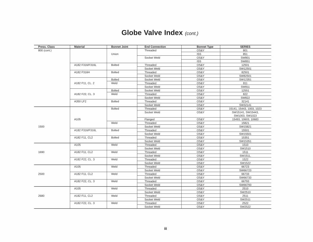
Globe Valve Index (cont.)
Press. Class Material Bonnet Joint End Connection Bonnet Type SERIES800 (cont.) Threaded OS&Y 801
Union ISS 851Socket Weld OS&Y SW801
ISS SW851A182 F316/F316L Bolted Threaded OS&Y 12501
Socket Weld OS&Y SW12501A182 F316H Bolted Threaded OS&Y 82501
Socket Weld OS&Y SW82501Bolted Socket Weld OS&Y SW12351
A182 F11, CL. 2 Weld Threaded OS&Y 811Socket Weld OS&Y SW811
Bolted Socket Weld OS&Y 12551A182 F22, CL. 3 Weld Threaded OS&Y 822
Socket Weld OS&Y SW822A350 LF2 Bolted Threaded OS&Y 32141
Socket Weld OS&Y SW32141Bolted Threaded OS&Y 15141, 15443, 1003, 1023
Socket Weld OS&Y SW15141, SW15443, SW1003, SW1023
A105 Flanged OS&Y 15493, 10603, 10683Weld Threaded OS&Y 15821
1500 Socket Weld OS&Y SW15821A182 F316/F316L Bolted Threaded OS&Y 15501
Socket Weld OS&Y SW15501A182 F11, CL2 Bolted Threaded OS&Y 15351
Socket Weld OS&Y SW15351A105 Weld Threaded OS&Y 1510
Socket Weld OS&Y SW15101690 A182 F11, CL2 Weld Threaded OS&Y 1511
Socket Weld OS&Y SW1511,A182 F22, CL. 3 Weld Threaded OS&Y 1522
Socket Weld OS&Y SW1522A105 Weld Threaded OS&Y 66723
Socket Weld OS&Y SW667232500 A182 F11, CL2 Weld Threaded OS&Y 66733
Socket Weld OS&Y SW66733A182 F22, CL. 3 Weld Threaded OS&Y 66793
Socket Weld OS&Y SW66793A105 Weld Threaded OS&Y 2510
Socket Weld OS&Y SW25102680 A182 F11, CL2 Weld Threaded OS&Y 2511
Socket Weld OS&Y SW2511A182 F22, CL. 3 Weld Threaded OS&Y 2522
Socket Weld OS&Y SW2522
iv
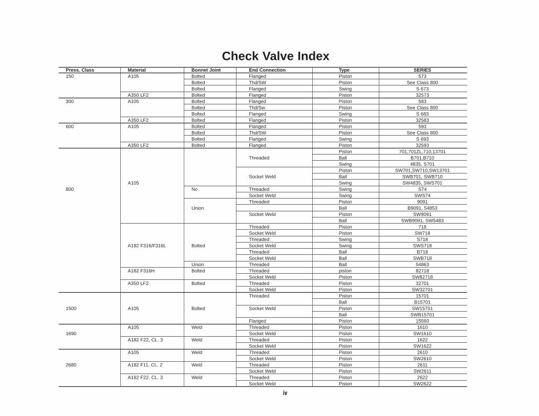
Check Valve IndexPress. Class Material Bonnet Joint End Connection Type SERIES150 A105 Bolted Flanged Piston 573
Bolted Thd/SW Piston See Class 800Bolted Flanged Swing S 673
A350 LF2 Bolted Flanged Piston 32573300 A105 Bolted Flanged Piston 583
Bolted Thd/Sw Piston See Class 800Bolted Flanged Swing S 683
A350 LF2 Bolted Flanged Piston 32583600 A105 Bolted Flanged Piston 593
Bolted Thd/SW Piston See Class 800Bolted Flanged Swing S 693
A350 LF2 Bolted Flanged Piston 32593Piston 701,701ZL,710,13701
Threaded Ball B701,B710Swing 4835, S701Piston SW701,SW710,SW13701
Socket Weld Ball SWB701, SWB710A105 Swing SW4835, SWS701
800 No Threaded Swing S74Socket Weld Swing SWS74Threaded Piston 9091
Union Ball B9091, 54853Socket Weld Piston SW9091
Ball SWB9091, SW5483Threaded Piston 718Socket Weld Piston SW718Threaded Swing S718
A182 F316/F316L Bolted Socket Weld Swing SWS718Threaded Ball B718Socket Weld Ball SWB718
Union Threaded Ball 54863A182 F316H Bolted Threaded piston 82718
Socket Weld Piston SW82718A350 LF2 Bolted Threaded Piston 32701
Socket Weld Piston SW32701Threaded Piston 15701
Ball B157011500 A105 Bolted Socket Weld Piston SW15701
Ball SWB15701Flanged Piston 15593
A105 Weld Threaded Piston 16101690 Socket Weld Piston SW1610
A182 F22, CL. 3 Weld Threaded Piston 1622Socket Weld Piston SW1622
A105 Weld Threaded Piston 2610Socket Weld Piston SW2610
2680 A182 F11, CL. 2 Weld Threaded Piston 2611Socket Weld Piston SW2611
A182 F22, CL. 3 Weld Threaded Piston 2622Socket Weld Piston SW2622

v
Meter Globe Valve Index
Hydraulic Check Valve Index
Press. Class Material Bonnet Joint End Connection Bonnet Type SERIES3000 A105 Screw Threaded ISS 1331T, 1881T, 2891T
Socket Weld ISS SW1871T, SW1331T, SW2891T4000 A105 Union Threaded ISS 54831T
Socket Weld ISS SW54381T5000 A105 Screw Threaded ISS 9871T, 9841T
Socket Weld ISS SW9871T, SW9841TA182 F316/F316L Screw Threaded ISS 98717T, 9841T
Socket Weld ISS SW9871T, SW9841TA182 F316/F316L Screw Threaded ISS 9871T, 9841T
Socket Weld ISS SW9871T, SW9841TA182 F316/F316L Screw Threaded ISS 9821T
Socket Weld ISS SW9821T6000 A105 Screw Threaded ISS 3991T
Socket Weld ISS SW3991T
Press. Class Material Bonnet Joint End Connection Bonnet Type SERIES3000 A105 Screw Threaded Piston 1551, 2191
Socket Weld Piston SW1551, SW2191Threaded Ball B1551Socket Weld Ball SWB1551
6000 A105 Screw Threaded Piston 4881Socket Weld Piston SW4881

vi
In the late 1890s, Vogt pioneered the early development of ammonia absorption refrigerationsystems that made artificial ice. This business, plus Vogt’s fledgling boiler business created aninternal need for quality valves that initiated Vogt’s early entry into the valve manufacturingbusiness. The early reputation of Vogt’s quality valves and the rapidly growing petroleumprocessing industry created an outside demand that would firmly establish Vogt in the massproduction of high quality forged steel valves.
For more than 100 years, Vogt’s leadership has been evident in the production of forged steelfittings, gate, globe, angle and check valves in most popular materials, trims and bonnetconfigurations.
Today, Vogt Valves supports a worldwide network of distributors with access to the world’slargest capability for the manufacturing of forged steel valves and fittings.
Vogt Valves, Sulphur Springs, TX
Vogt Valves – A History in the Making

1
Page Nos.
Index by Valve Type ............................................................................................ i-vIndex .....................................................................................................................2-3Description of No. System .................................................................................... 4Gate Valves.........................................................................................................5-43Nuclear ...................................................................................................................44Sour Service...........................................................................................................45Globe Valves .................................................................................................... 46-87Check Valves ...................................................................................................89-111Engineering Tables ........................................................................................112-123Fittings & Unions...........................................................................................124-132Spare Parts ..................................................................................................140-143
Abbreviations & Terms Used in the Valve & Fitting Industry, Glossary of............134
ASTM Material Specs. Cross Reference ............................................................117
Auxiliary Operators.................................................................................................88
Care & Maintenance of Vogt Valves .............................................................137-139
Conversions: Weight, Pressure & Temperature ..........................................148-149
Cv Factors ....................................................................................................122-123
Page Nos.
Cv Formulas..................................................................................................120-121
Dimensional Data for Standard & Schedule Pipe ........................................145-146
Materials (Forging) ...............................................................................................118Materials (Valve Trim)...........................................................................................119Materials (General Use) .......................................................................................119
Packaging Data for Fittings .................................................................................126
Pressure-Temperature Service Ratings.........................................................112-115
Replacement Parts...............................................................................................138
Series Number Index ............................................................................................2-3
Standards for Valve & Fitting Industry ..........................................................135-136
Limited Warranty ..................................................................................................133
Thread & Socket Weld Standards........................................................................144
Valve Packing Materials .......................................................................................116
Catalog Sections
PAGE NOS.Check Valves Gate Valves Globe Valves
Alkylation (HF) 93, 97 7, 9, 11, 12, 14, 21 53, 54, 55, 59ASTM A350, Gr. LF2 ( to -50°F) 90-92, 99 6-8, 18, 38, 43 47-49, 55API-600 Wall Thicknesses 94 10, 33, 35, 36 51, 71, 72, 73Extended Body 25-29, 41 62Bellowseal 13, 20, 22, 47-49, 52Chlorine 50, 61Cryogenic (to -325°F) F316, F316L 17 57 Flow Control 63, 64, 76Hydraulic 109-111 83-87(NACE MR-01-75) Sour Service * 45 45 45Nuclear 44 44 44Y-Pattern 107, 108 68, 78, 80-82Zero Leakage 100
* GIobe, Angle and Check Valves can be provided with appropriate trim materials for sour service. Valve series with MB6, MB8 and MBS suffixes meet NACE. See pages 4 and 45 for explanation.
Service Application
Table of Contents

2
S 74..........................96SWS 74 .........................96
229...............126-128SW 229 .......126,127,130
243...............126-128 SW 243 .......126,127,130
259...............126-128273...............126-128
353..........................6BW 353..........................6
353F8M .................6BW 363F8M...................7
353FHF...................6353MB8 ..................6353MM....................6353R .....................20
BW 353R .....................20353T........................6358..........................6363..........................7
BW 363..........................7363FHF...................7363MB8 ..................7363MM ...................7
BW 363MM....................7363R .....................20
BW 363R .....................20368..........................7373 .........................8
BW 373..........................8373F8M...................8
BW 373F8M...................8373FHF...................8373MB8 ..................8373MM....................8
BW 373MM....................8373R .....................20
BW 373R .....................20378..........................8
473........................47473B .....................47473F8M.................47473MB8 ................47473MM..................47483........................48483B .....................48483F8M.................48483MB8 ................48483MM..................48493........................49493B .....................49493F8M.................49493MB8 ................49493MM..................49
SW 503...............126,130573........................90573F8M.................90
573MB8 ................90573MBS................90573MM..................90583........................91583F8M.................91583MB8 ................91583MBS................91583MM..................91593........................92593F8M.................92593MB8 ................92593MBS................92593MM..................92
SW 623...............126,130S 673 .....................95AS 683 .....................95BS 693 .....................95C
701......................100S 701........................95
SW 701......................100SWS 701........................95
701F8M...............100SW 701F8M...............100
701MB8 ..............100SW 701MB8 ..............100
701MBS..............100SW 701MBS..............100
701MM................100SW 701MM................100
701ZLB ...............100701ZLE ...............100701ZLN...............100701ZLV ...............100
B 701........................97SWB 701........................97SWB 701HF6.................97SWB 701HF7 .............. 97
710........................98B 710........................98
SW 710........................98SWB 710........................98
710FHF.................98SW 710FHF.................98
718........................99B 718........................97S 718........................95
SW 718........................99SWB 718........................97SWS 718........................95
718T......................99SW 718T......................99
801........................69SW 801........................69
810........................68SW 810........................68
811 ........................68SW 811 ........................68
822........................68SW 822........................68
851........................70SW 851........................70
1003......................73SW 1003......................73
1023......................73SW 1023......................73
1033......................36SW 1033......................36
1043......................36SW 1043......................36
1160.............126-128SW 1160 ......126,127,130
SWT 1160 ......126,128,1301189.............126-128
1211.............126-128SW 1211 ......126,127,130
SWT 1211 ......126,128,1301260.............126-1281280.............126-1281299.............126,127
SW 1299......126-128,130
1331T....................83SW 1331T....................83
1399.............126-128SW 1399......126,127,130
1510......................78R 1510......................80
SW 1510......................78SWR 1510......................80
1511 ......................78R 1511 ......................80
SW 1511 ......................78SWR 1511 ......................80
1522......................78R 1522......................80
SW 1522......................78SWR 1522......................80
1551....................109B 1551....................109
SW 1551....................109SWB 1551....................109
1610....................107SW 1610....................107
1622....................107SW 1622....................107
1800.............126-1281871T....................83
SW 1871T....................831899.............126,127
SW 1899......126-128,130
1931......126,127,132SW 1931.............126,127
1951......126,127,132SW 1951......126,127,132
1961......126,127,132SW 1961.............126,127
1971......................65SW 1971......................65
2001.............126-128SW 2001......126,127,130
2024.............126,127SW 2024......126-128,130
2090.............126-128SW 2090......126,127,130
2110.............126-128SW 2110 ......126,127,130
2130.............126-1282191 ....................110
SW 2191 ....................1102199.............126-128
SW 2199......126,127,130
2271....................125SW 2271....................125
2324.............126-128SW 2324......126,127,130
2350......126-128,130SW 2350.............126,127
2370.............126-128
2400.............126-1282450.............126-128
SW 2450......126,127,130
2510......................81R 2510......................82
SW 2510......................81SWR 2510......................82
2511 ......................81R 2511 ......................82
SW 2511 ......................81SWR 2511 ......................82
2522......................81R 2522......................82
SW 2522......................81SWR 2522......................82
2560.............126-1282580.............126-128
2610....................108SW 2610....................108
2611 ....................108SW 2611 ....................108
2622....................108SW 2622....................108
2670.............127,128SW 2670....................127
2801......................24
SW 2801......................242801B ...................13
SW 2801B ...................132801F8M...............24
SW 2801F8M...............242801FHF...............24
SW 2801FHF...............242801MB6 ..............24
SW 2801MB6 ..............242801MB8 ..............24
SW 2801MB8 ..............242801MBS..............24
SW 2801MBS..............242801MM................24
SW 2801MM................24TSW 2801......................24TSW 2801FHF...............24
CT 2801......................25SS 2801......................26ST 2801......................26TT 2801......................26ST 2801FHF...............26ST 2801F8M...............26TT 2801F8M...............26SS 2801MB6 ..............26ST 2801MB6 ..............26ST 2801MB8 ..............26ST 2801MM................26TT 2801MM................26
2811 ......................312811FHF ...............31
SW 2811FHF ...............31SW 2811 ......................31
TSW 2811 ......................31TT 2811 ......................26
2821......................67SW 2821......................67
2821FHF...............67SW 2821FHF...............67
2821F8M...............67SW 2821F8M...............67
2831......................30CT 2831......................25ST 2831......................26
2831T....................30TT 2831......................26
2891T....................84SW 2891T....................84BT 2901......................25CT 2901......................25CS 2901......................25BT 2901MB6 ..............25CT 2911 ......................25
3991T....................87SW 3991T....................87
4001.............126-128SW 4001......126,127,130
4200.............126-128SW 4200......126,127,130
4823.............126-128SW 4823......126,127,130
4835......................94SW 4835......................94
4881 ....................111SW 4881 ....................111
5061....................125
6281....................125
9091....................104B 9091....................104
SW 9091....................104SWB 9091....................104
9821T....................86SW 9821T....................86
9841T....................86SW 9841T....................86
9871T....................86SW 9871T....................86
10103....................71SW 10103....................71
10403....................5110603....................7210683....................72
11103 ....................33SW 11103 ....................33
11403 ....................1011603 ....................3511683 ....................35
12111 ....................14BS 12111 ....................27BT 12111 ....................27CT 12111 ....................27ST 12111 ....................28
SW 12111 ....................14TSW 12111 ....................14
TT 12111 ....................2912111ER ...............19
ST 12111ER ...............28SW 12111ER ...............19
12111F8M .............14SW 12111F8M .............14
12111FHF .............14TT 12111FHF .............29
SW 12111FHF .............14SW 12111HF6 .............14SW 12111HF7 .............14
12111MM ..............14SW 12111MM ..............14
12111MB6.............14ST 12111MB6.............28
Series No. Page No. Series No. Page No. Series No. Page No. Series No. Page No. Series No. Page No. Series No. Page No.
Index
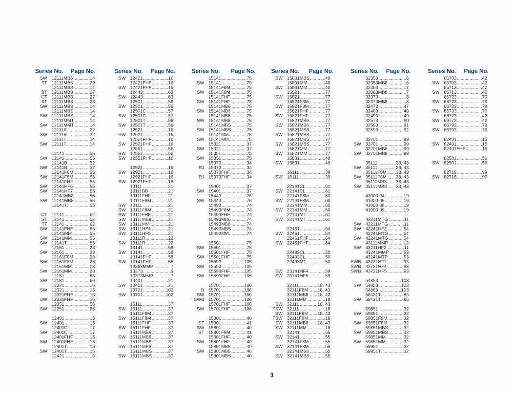
3
SW 12111MB6.............14TT 12111MB6.............29
12111MB8.............14BT 12111MB8.............27CT 12111MB8.............27ST 12111MB8.............28
SW 12111MB8.............1412111MBS ............14
SW 12111MBS ............1412111MMT ............14
SW 12111MMT ............1412111R..................22
SW 12111R..................2212111T ..................14
SW 12111T ..................14
12141....................55SW 12141....................55
12141B .................52SW 12141B .................52
12141F8M.............55SW 12141F8M.............55
12141FHF.............55SW 12141HF6.............55SW 12141HF7.............55
12141MB8 ............55SW 12141MB8 ............55
12141T..................55
CT 12141....................62ST 12141....................62TT 12141....................62
SW 12141FHF.............5512141MM..............55
SW 12141MM..............55SW 12141T..................55
12161....................23SW 12161....................23
12161F8M.............23SW 12161F8M.............23
12161MM..............23SW 12161MM..............23
12181....................66SW 12181....................66
12321....................16SW 12321....................16
12321FHF.............16SW 12321FHF.............16
12351....................56SW 12351....................56
12401....................15SW 12401....................15
12401C .................17SW 12401C .................17
12401FHF.............15SW 12401FHF.............15
12401T..................15SW 12401T..................15
12421....................16
SW 12421....................1612421FHF.............16
SW 12421FHF.............1612443....................63
SW 12443....................6312501....................56
SW 12501....................5612501C .................57
SW 12501C .................5712501T..................56
SW 12501T..................5612521....................16
SW 12521....................1612521FHF.............16
SW 12521FHF.............1612551....................56
SW 12551....................56SW 12551FHF.............16
12921....................16SW 12921....................16
12921FHF.............16SW 12921FHF.............16
13111 ....................2113111BB ...............2113111FHF .............2113111F8M .............21
SW 13111 ....................21SW 13111F8M .............21SW 13111FHF .............21SW 13111MB8.............21SW 13111MM ..............21SW 13111HF4 .............21SW 13111HF5 .............21
13111R..................22SW 13111R..................22
13141....................58SW 13141....................58
13141FHF.............58SW 13141FHF.............58
13363MMP .............713373......................913373MMP .............713401....................21
SW 13401....................2113701..................102
SW 13701..................102
15111 ....................37SW 15111 ....................37
15111F8M .............37SW 15111F8M .............37
15111FHF .............37SW 15111FHF .............37
15111MB6.............37SW 15111MB6.............37
15111MB8.............37SW 15111MB8.............37
15111MBS ............37SW 15111MBS ............37
15141....................75SW 15141....................75
15141F8M.............75SW 15141F8M.............75
15141FHF.............75SW 15141FHF.............75
15141MB6 ............75SW 15141MB6 ............75
15141MB8 ............75SW 15141MB8 ............75
15141MBS............75SW 15141MBS............75
15141MM..............75SW 15141MM..............75
15321....................37SW 15321....................37
15351....................75SW 15351....................75
15373....................34RJ 15373....................34
15373FHF.............34RJ 15373FHF.............34
15401....................37SW 15401....................37
15443....................76SW 15443....................76
15493....................7415493F8M.............7415493FHF.............7415493MB6 ............7415493MB8 ............7415493MBS............7415493MM..............74
15501....................75SW 15501....................75
15501FHF.............75SW 15501FHF.............75
15593..................105SW 15593..................105
15593FHF...........105SW 15593FHF...........105
15701..................106B 15701..................106
SW 15701..................106SWB 15701..................106
15701FHF...........106SW 15701FHF...........106
15801....................40ST 15801....................41
SW 15801....................40ST 15801F8M.............41
15801FHF.............40SW 15801FHF.............40
15801MB8 ............40SW 15801MB8 ............40
15801MBS............40
SW 15801MBS............4015801MM..............40
SW 15801MM..............4015821....................77
SW 15821....................7715821F8M.............77
SW 15821F8M.............7715821FHF.............77
SW 15821FHF.............7715821MB6 ............77
SW 15821MB6 ............7715821MB8 ............77
SW 15821MB8 ............7715821MBS............77
SW 15821MBS............7715821MM..............77
SW 15821MM..............7715831....................40
SW 15831....................40
16111 ....................39SW 16111 ....................39
22141CL ...............61SW 22141CL ...............61
22141F8M.............60SW 22141F8M.............60
22141MM..............60SW 22141MM..............60
22141MT...............61SW 22141MT...............61
22461....................64SW 22461....................64
22461FHF.............64SW 22461FHF.............64
22483CL ...............5022493CL ...............5022493MT...............50
SW 23141HF4.............59SW 23141HF5.............59
32111 ..............18, 4332111F8M.......18, 4332111MB8.......18, 4332111MM ..............18
SW 32111 ..............18, 43TSW 32111 ....................18
SW 32111F8M.......18, 43TSW 32111F8M .............18
SW 32111MB8.......18, 43SW 32111MM ..............18
32141....................55SW 32141....................55
32141F8M.............55SW 32141F8M.............55
32141MB8 ............55SW 32141MB8 ............55
32353......................632353MB8 ..............632363......................732363MB8 ..............732373......................832373MB8 ..............832473....................4732483....................4832493....................4932573....................9032583....................9132593....................92
32701....................99SW 32701....................99
32701MB8 ............99SW 32701MB8 ............99
35111 ..............38, 43SW 35111 ..............38, 43
35111F8M.......38, 43SW 35111F8M.......38, 43
35111MB8.......38, 43SW 35111MB8.......38, 43
41000 04...............1941000 06...............1941000 08...............1941000 09...............19
42211MTG ............11SW 42211MTG ............11SW 42241HF2.............54
42241MTG............54SW 42241MTG............54
43111MMP............12SW 43211HF2 .............11
43241MMP ...........5343241MTP ............53
SWB 43721HF2.............93SWB 43721HF4.............93SWB 43721HF5.............93
54853..................103SW 54853..................103
54863..................10358431T..................85
SW 58431T..................85
59851....................32SW 59851....................32
59851F8M.............32SW 59851F8M.............32
59851MBS............32SW 59851MBS............32
59851MM..............32SW 59851MM..............32
59951....................3259951T..................32
66703....................42SW 66703....................42
66713....................42SW 66713....................42
66723....................79SW 66723....................79
66733....................79SW 66733....................79
66773....................42SW 66773....................42
66793....................79SW 66793....................79
82401....................15SW 82401....................15
82401FHF.............15
82501....................56SW 82501....................56
82718....................99SW 82718....................99
Series No. Page No. Series No. Page No. Series No. Page No. Series No. Page No. Series No. Page No. Series No. Page No.

SW 12111 F8M
Series Number(typical)
Prefix:This maximum 3 alphameric letter beginning the Vogt Valve seriesnumber is normally indicative of the valve connection. Historically, a fewdesign features have also been used as part of the prefix including S, Band R. A fully female threaded valve as the traditional Vogt standarddoes not have a prefix number (see below for prefix descriptions).
Suffix:This maximum 3 alphameric character ending of the Vogt Valveseries number is normally indicative of the valve internal trimpackage. Historically, packing and a few design features have alsobeen used as part of the suffix number including T, B and ER. Avalve with the traditional Vogt standard trim package and packingis not assigned a suffix number (see below for suffix descriptions).
Prefix Description:(Blank) - Female NPT (both ends)B - Ball Check (female NPT)BS - Female SW by Male Butt WeldBT - Female Thd by Male Butt WeldBW - Butt WeldCS - Female SW by Male Couplet CT - Female Thd by Male Couplet R - In-Line Repair (female NPT)RJ - Ring Joint Flanges S - Swing Check (female NPT)SS - Female SW by Male SW ST - Female Thd by Male SW SW - Socket Weld SWB - Ball Check (SW) SWR - In-line Repairable (SW) SWS - Swing Check (SW) TS - Female SW by Male Thd TSW - Female Thd by Female SW TT - Female Thd by Male Thd
Suffix Description:(Blank) – Standard TrimB – Bellows Valve C – Cryogenic Valve CL – Chlorine Valve Trim – Monel/Hastelloy ER – Emissions Reduction – Double Packed with Lantern Ring F8M– 316 TrimFHF – Full Hard Face (unless standard) FH8 – Full Hard Faced F8M TrimFHT – Teflon Packing and Full Hard FaceHF – Hard Faced Disc (F316 Globes and Checks Only) HF2 – UOP Alkylation HF4 – UOP Alkylation HF5 – UOP Alkylation HF6 – UOP Alkylation HF7 – UOP Alkylation L – Locking Device MB6 – 13% Chrome Trim – NACE MB8 – 316 Trim Hard Faced Seats and Disc/Wedge – NACE MBS – Monel Trim – NACE MM – Monel Trim – Grafoil Packing and Gasket MMP – Phillips Alkylation MMT – Monel Trim – Teflon Packing and Gasket MT – Chlorine Valve Trim – Monel/Teflon Disc/HastelloyMTG – Vogt Alkylation MTP – Phillips Alkylation R– Reactive Seal T – Teflon Packing and Gasket ZLB – Zero Leakage Check Valve – Buna N ZLE – Zero Leakage Check Valve – Ethylene Propylene ZLN – Zero Leakage Check Valve – Neoprene ZLV – Zero Leakage Check Valve – Viton 14
Valve Design/Material:This maximum 5 numeric character uniquelyidentifies the valve to its design (gate, globe,angle, check, etc.) and pressure boundary materialof construction (A105, A182-F5, F11, F316, etc.).The prefix and suffix to this number provide detailsto the design, end connections and trim optionincluding packing.
Legend:The prefixes and suffixes based ondesign are limited to S, B, R and ER (as listed above) ONLY.
Expansion of new valve designs areadded as new SERIES NUMBERS.
(See the VV 200 individual pages forstandard series available.)
Description of Series Number System for Vogt Valves(Order Vogt Valves & Fittings by size—series number)
4

5
Gate valves are designed to
operate in a fully open or fully
closed position. When open, the
media will flow with minimal
turbulence and pressure drop
through the valve.
Vogt gate valves are available
with a variety of bonnet types,
body and trim materials and stem
packings in addition to a broad
range of pressure classes, and
end connections including
extended bodies.
The rugged construction of
FORGED gate valves provide
an extended life of safe
operation. Metal-to-metal seating
surfaces accommodate the
widest range of pressure-
temperature service conditions.
Gate Valve Section – Pages 5-43
Dimensions are in inches and millimeters.
Dimensions are subject to change without notice.
Order by Size and Series Number.
SEAL WELDED BONNETGATE VALVE
BOLTED BONNETGATE VALVE
BOLTED BONNETGATE VALVE
6
Forged Gate Valves
GA
TE
CL
AS
S 1
50 (
PN
20)
353,
323
53, 3
58
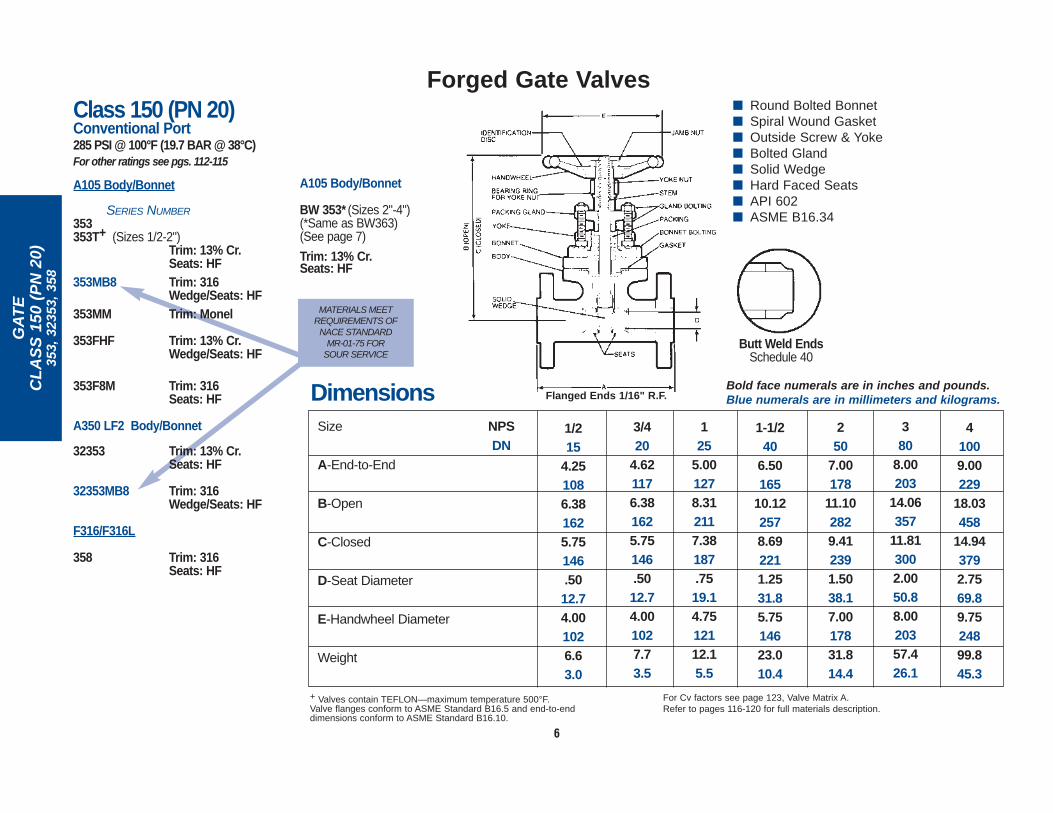
■ Round Bolted Bonnet■ Spiral Wound Gasket■ Outside Screw & Yoke■ Bolted Gland■ Solid Wedge■ Hard Faced Seats■ API 602■ ASME B16.34
Size
A-End-to-End
B-Open
C-Closed
D-Seat Diameter
E-Handwheel Diameter
Weight
Dimensions Bold face numerals are in inches and pounds.Blue numerals are in millimeters and kilograms.
+ Valves contain TEFLON—maximum temperature 500°F.Valve flanges conform to ASME Standard B16.5 and end-to-enddimensions conform to ASME Standard B16.10.
For Cv factors see page 123, Valve Matrix A.Refer to pages 116-120 for full materials description.
250
7.00178
11.102829.412391.5038.17.0017831.814.4
1-1/240
6.50165
10.122578.692211.2531.85.7514623.010.4
380
8.00203
14.06357
11.813002.0050.88.0020357.426.1
41009.00229
18.03458
14.943792.7569.89.7524899.845.3
NPSDN
3/420
4.621176.381625.75146.5012.74.001027.73.5
125
5.001278.312117.38187.7519.14.7512112.15.5
1/215
4.251086.381625.75146.5012.74.001026.63.0
MATERIALS MEETREQUIREMENTS OF
NACE STANDARD MR-01-75 FOR
SOUR SERVICEButt Weld Ends
Schedule 40
A105 Body/Bonnet
BW 353* (Sizes 2"-4")(*Same as BW363)(See page 7)
Trim: 13% Cr. Seats: HF
Class 150 (PN 20)Conventional Port285 PSI @ 100°F (19.7 BAR @ 38°C)For other ratings see pgs. 112-115
A105 Body/Bonnet
SERIES NUMBER353353T+ (Sizes 1/2-2")
Trim: 13% Cr. Seats: HF
353MB8 Trim: 316 Wedge/Seats: HF
353MM Trim: Monel
353FHF Trim: 13% Cr. Wedge/Seats: HF
353F8M Trim: 316Seats: HF
A350 LF2 Body/Bonnet
32353 Trim: 13% Cr. Seats: HF
32353MB8 Trim: 316Wedge/Seats: HF
F316/F316L
358 Trim: 316Seats: HF
Flanged Ends 1/16" R.F.

7
Forged Gate Valves
GA
TE
CL
AS
S 3
00 (
PN
50)
363,
133
63M
MP,
323
63, 3
68
Size
A-End-to-End
B-Open
C-Closed
D-Seat Diameter
E-Handwheel Diameter
Weight
1/215
5.501406.381625.75146.5012.74.001028.03.6
3/420
6.001526.381625.75146.5012.74.0010210.94.9
125
6.501658.312117.38187.7519.14.7512115.47.0
250
8.50216
11.102829.412391.5038.17.0017824.911.3
2-1/265
9.50241
14.06357
11.813002.0050.88.0020334.215.5
380
11.12282
14.06357
11.813002.0050.88.0020344.220.1
4100
12.00305
18.03458
14.943792.7569.89.7524877.135.0
Bold face numerals are in inches and pounds.Blue numerals are in millimeters and kilograms.
Valve flanges conform to ASME Standard B16.5 and end-to-endDimensions conform to ASME Standard B16.10.
For Cv factors see page 123, Valve Matrix A.Refer to pages 116-120 for full materials description.
250
8.50216
11.102829.412391.5038.17.0017839.618.0
1-1/240
7.50190
10.122578.692211.2531.85.7514629.213.3
380
11.12282
14.06357
11.813002.0050.88.0020367.530.6
4100
12.00305
18.03458
14.943792.7569.89.7524812757.7
NPSDN
Butt Weld Ends:
■ Round Bolted Bonnet■ Spiral Wound Gasket■ Outside Screw & Yoke■ Bolted Gland■ Solid Wedge■ Hard Faced Seats■ API 602■ ASME B16.34
Butt Weld EndsSchedule 40
Flanged Ends: 1/16" R.F.
MATERIALS MEETREQUIREMENTS OF
NACE STANDARD MR-01-75 FOR
SOUR SERVICE
Class 300 (PN 50)Conventional Port740PSI @ 100°F (51.0 BAR @ 38°C)For other ratings see pgs. 112-115
A105 Body/Bonnet
SERIES NUMBER363 Trim: 13% Cr.
Seats: HF363MB8 Trim: 316
Wedge/Seats: HF
363FHF Trim: 13% Cr. Wedge/Seats: HF
363MM Trim: Monel
13363MMP (Size 2" Only) (Full Port)Trim: Monel
Listed in Phillips Petroleum Company’s HF Alkylation Process Design Spec. Manual.
BW 363 (Sizes 2"-4") Trim: 13% Cr. Seats: HF
BW 363F8M Trim: 316Seats: HF
BW 363MM Trim: Monel
A350 LF2 Body/Bonnet
32363 Trim: 13% Cr. Seats: HF
32363MB8 Trim: 316Wedge/Seats: HF
F316/F316L
368 Trim: 316Seats: HF
8
Forged Gate Valves
GA
TE
CL
AS
S 6
00 (
PN
110
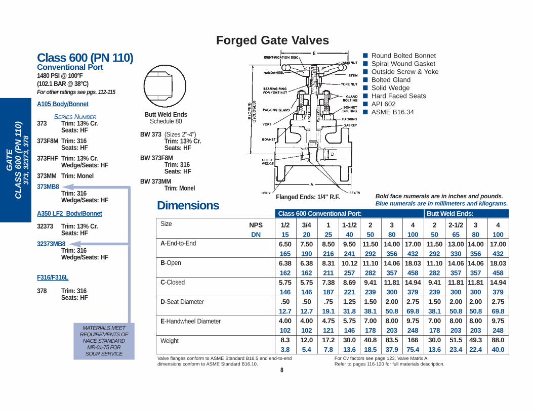
)37
3, 3
2373
, 378
Size
A-End-to-End
B-Open
C-Closed
D-Seat Diameter
E-Handwheel Diameter
Weight
3/420
7.501906.381625.75146.5012.74.0010212.05.4
125
8.502168.312117.38187.7519.14.7512117.27.8
1-1/240
9.50241
10.122578.692211.2531.85.7514630.013.6
250
11.50292
11.102829.412391.5038.17.0017840.818.5
NPSDN
DimensionsBold face numerals are in inches and pounds.Blue numerals are in millimeters and kilograms.
1/215
6.501656.381625.75146.5012.74.001028.33.8
Class 600 Conventional Port: Butt Weld Ends:
Valve flanges conform to ASME Standard B16.5 and end-to-enddimensions conform to ASME Standard B16.10.
For Cv factors see page 123, Valve Matrix A.Refer to pages 116-120 for full materials description.
■ Round Bolted Bonnet■ Spiral Wound Gasket■ Outside Screw & Yoke■ Bolted Gland■ Solid Wedge■ Hard Faced Seats■ API 602■ ASME B16.34
Flanged Ends: 1/4" R.F.
Butt Weld EndsSchedule 80
Class 600 (PN 110)Conventional Port1480 PSI @ 100°F (102.1 BAR @ 38°C)For other ratings see pgs. 112-115
A105 Body/Bonnet
SERIES NUMBER373 Trim: 13% Cr.
Seats: HF
373F8M Trim: 316Seats: HF
373FHF Trim: 13% Cr. Wedge/Seats: HF
373MM Trim: Monel
373MB8Trim: 316 Wedge/Seats: HF
A350 LF2 Body/Bonnet
32373 Trim: 13% Cr. Seats: HF
32373MB8Trim: 316Wedge/Seats: HF
F316/F316L
378 Trim: 316Seats: HF
BW 373 (Sizes 2"-4")Trim: 13% Cr. Seats: HF
BW 373F8MTrim: 316Seats: HF
BW 373MMTrim: Monel
MATERIALS MEETREQUIREMENTS OF
NACE STANDARD MR-01-75 FOR
SOUR SERVICE
380
14.00356
14.06357
11.813002.0050.88.0020383.537.9
4100
17.00432
18.03458
14.943792.7569.89.7524816675.4
250
11.50292
11.102829.412391.5038.17.0017830.013.6
2-1/265
13.00330
14.06357
11.813002.0050.88.0020351.523.4
380
14.00356
14.06357
11.813002.0050.88.0020349.322.4
4100
17.00432
18.03458
14.943792.7569.89.7524888.040.0
9
Forged Gate Valves
GA
TE
CL
AS
S 6
00 (
PN
110
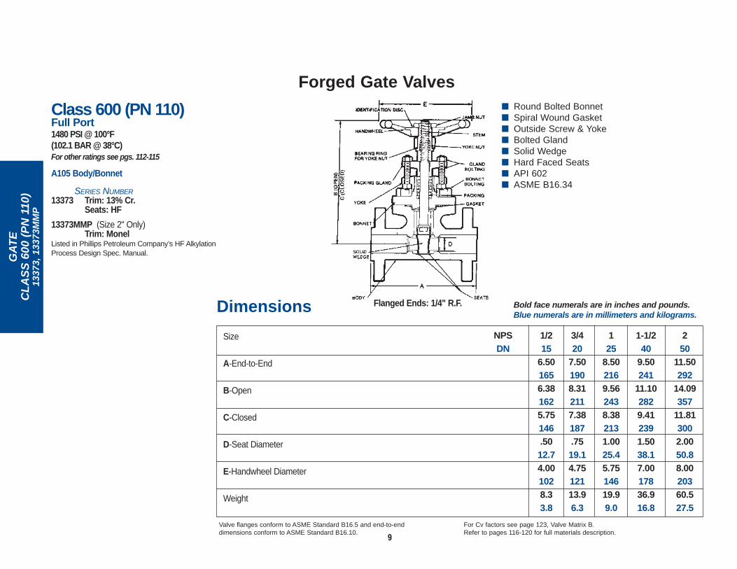
)13
373,
133
73M
MP
Size
A-End-to-End
B-Open
C-Closed
D-Seat Diameter
E-Handwheel Diameter
Weight
NPSDN
Dimensions Bold face numerals are in inches and pounds.Blue numerals are in millimeters and kilograms.
3/420
7.501908.312117.38187.7519.14.7512113.96.3
125
8.502169.562438.382131.0025.45.7514619.99.0
1-1/240
9.50241
11.102829.412391.5038.17.0017836.916.8
250
11.50292
14.09357
11.813002.0050.88.0020360.527.5
1/215
6.501656.381625.75146.5012.74.001028.33.8
Valve flanges conform to ASME Standard B16.5 and end-to-enddimensions conform to ASME Standard B16.10.
For Cv factors see page 123, Valve Matrix B.Refer to pages 116-120 for full materials description.
Flanged Ends: 1/4" R.F.
Class 600 (PN 110)Full Port1480 PSI @ 100°F (102.1 BAR @ 38°C)For other ratings see pgs. 112-115
A105 Body/Bonnet
SERIES NUMBER13373 Trim: 13% Cr.
Seats: HF
13373MMP (Size 2" Only)Trim: Monel
Listed in Phillips Petroleum Company’s HF AlkylationProcess Design Spec. Manual.
■ Round Bolted Bonnet■ Spiral Wound Gasket■ Outside Screw & Yoke■ Bolted Gland■ Solid Wedge■ Hard Faced Seats■ API 602■ ASME B16.34

10
Forged Gate Valves
GA
TE
CL
AS
S 6
00 (
PN
110
)11
403
Size
A-End-to-End
B-Open
C-Closed
D-Seat Diameter
E-Handwheel Diameter
Weight
125
8.50216
12.56319
11.442911.0025.47.0017845.020.4
1-1/432
9.00229
14.12359
12.623211.2531.88.0020357.426.1
Bold face numerals are in inches and pounds.Blue numerals are in millimeters and kilograms.
1/215
6.50165
10.442659.69246.5614.24.7512119.58.9
3/420
7.50190
11.31287
10.38264.7519.15.7514631.214.2
1-1/240
9.50241
16.38416
14.693731.5038.19.7524876.234.6
250
11.50292
19.00483
16.814272.0050.89.7524810547.7
NPSDN
Dimensions
2-1/265
13.00330
21.75552
19.004832.3158.712.0030516976.7
380
14.00356
24.00610
20.755272.8171.413.7534922099.9
Valve flanges conform to ASME Standard B16.5 and end-to-enddimensions conform to ASME Standard B16.10.
For Cv factors see page 123, Valve Matrix C.Refer to pages 116-120 for full materials description.
■ Round Bolted Bonnet■ Spiral Wound Gasket■ Outside Screw & Yoke■ Bolted Gland■ Solid Wedge■ Hard Faced Seats■ ASME B16.34
Flanged Ends: 1/4" R.F.
Class 600 (PN 110)Full Port (Except 2-1/2 & 3)1480 PSI @ 100°F (102.1 BAR @ 38°C)For other ratings see pgs. 112-115
A105 Body/Bonnet
SERIES NUMBER
11403 Trim: 13% Cr. Seats: HF
Meets API-600 required wall thicknesses

11
Forged Gate Valves For HF Alkylation Service
GA
TE
CL
AS
S 8
00 (
PN
130
)42
211M
TG
, 432
11H
F2
■ Round Bolted Bonnet■ Spiral Wound Gasket■ Outside Screw & Yoke■ Bolted Gland■ Double Packing■ Lantern Ring■ Grease Injector■ Solid Wedge■ ASME B16.34
Size
A-End-to-End
B-Open
C-Closed
D-Seat Diameter
E-Handwheel Diameter
Weight
1/215
3.3886
8.162077.56192.5012.74.001025.42.5
3/420
3.3886
8.162077.56192.5012.74.001025.82.6
125
4.00102
10.282619.36238.7519.14.751219.84.4
1-1/240
4.75121
12.12308
10.722721.2531.85.7514617.68.0
250
5.25133
13.38340
11.692971.5038.17.0017823.010.4
NPSDN
DimensionsBold face numerals are in inches and pounds.Blue numerals are in millimeters and kilograms.
+ Valves contain TEFLON—maximum temperature 500°F.Refer to pages 116-120 for full materials description.
For Cv factors see page123, Valve Matrix B.
1/215
3.3886
8.162077.56192.5012.74.001025.82.6
3/420
4.00102
10.282619.36238.7519.14.751219.84.4
125
4.38111
11.38289
10.162581.0025.45.7514617.68.0
42211MTG: SW43211HF2:
For Cv factors see page123, Valve Matrix A.
Class 800 (PN 130)Conventional Port1975 PSI @ 100°F (136.2 BAR @ 38°C)For other ratings see pgs. 112-115
A105 Body/Bonnet
SERIES NUMBERThreaded Socket Weld42211MTG+ SW42211MTG+
Trim: Monel
Class 800 (PN 130)Full Port1975 PSI @ 100°F (136.2 BAR @ 38°C)For other ratings see pg. 121
A105 Body/Bonnet
SERIES NUMBERThreaded Socket Weld
– SW43211HF2Trim: Monel
HYDROFLUORIC ACID (HF)
ALKYLATION VALVES.UOPAPPROVED.

12
Forged Gate Valves For HF Alkylation Service
CL
AS
S 6
00 (
PN
110
)43
111M
MP
■ Round Bolted Bonnet■ Spiral Wound Gasket■ Outside Screw & Yoke■ Bolted Gland■ Solid Wedge■ API 602■ ASME B16.34
Class 600 (PN 110)Full Port1480 PSI @ 100°F (102.1 BAR @ 38°C)For other ratings see pgs. 112-115
A105 Body/Bonnet
SERIES NUMBER Threaded Socket Weld43111MMP+ –Trim: Monel
Listed in Phillips Petroleum Company’s HF Alkylation Process Design Spec. Manual.
Size
A-End-to-End
B-Open
C-Closed
D-Seat Diameter
E-Handwheel Diameter
Weight
NPSDN
Dimensions Bold face numerals are in inches and pounds.Blue numerals are in millimeters and kilograms.
+Valves contain TEFLON — maximum temperature 500°F.Refer to pages 116-120 for full materials description.
For Cv factors see page 123, Valve Matrix B.
1/215
3.3886
6.381625.75146.5012.74.001025.02.3
3/420
4.001028.312117.38187.7519.14.751218.33.8
125
4.381119.562438.382131.0025.45.7514612.15.5

13
Forged Gate Valves Bellowseal
CL
AS
S 8
00 (
PN
130
)28
01B
■ Welded Bonnet■ Outside Screw & Yoke■ Bolted Gland■ Seamless Multi-Ply Bellows■ Full Hard Faced■ ASME B16.34
Class 800 (PN 130)Conventional Port1975 PSI @ 100°F (136.2 BAR @ 38°C)For other ratings see pgs. 112-115
A105 Body/Bonnet
SERIES NUMBER Threaded Socket Weld2801B SW2801B
Stem: 316Bellows: 321SSWedge/Seats: HF
Size
A-End-to-End
B-Open
C-Closed
D-Seat Diameter
E-Handwheel Diameter
Weight
1/215
3.3886
10.56268
10.06256.5012.74.001024.21.9
3/420
3.3886
10.56268
10.06256.5012.74.001028.84.0
125
4.00102
12.88327
12.12308.7519.14.751218.53.9
1-1/240
5.25133
20.25514
18.814781.5038.17.0017828.312.8
250
5.25133
20.25514
18.814781.5038.17.0017827.812.6
NPSDN
Dimensions Bold face numerals are in inches and pounds.Blue numerals are in millimeters and kilograms.
Refer to pages 116-120 for full materials description. For Cv factors see page 123, Valve Matrix D.
14
Forged Gate Valves
GA
TE
CL
AS
S 8
00 (
PN
130
)12
111
MATERIALS MEETREQUIREMENTS OF
NACE STANDARD MR-01-75 FOR
SOUR SERVICE
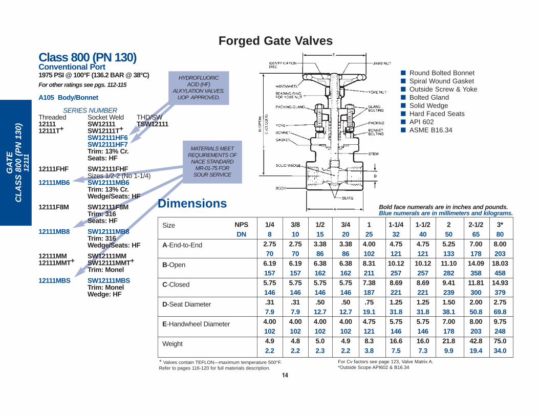
■ Round Bolted Bonnet■ Spiral Wound Gasket■ Outside Screw & Yoke■ Bolted Gland■ Solid Wedge■ Hard Faced Seats■ API 602■ ASME B16.34
Size
A-End-to-End
B-Open
C-Closed
D-Seat Diameter
E-Handwheel Diameter
Weight
1-1/432
4.75121
10.122578.692211.2531.85.7514616.67.5
Bold face numerals are in inches and pounds.Blue numerals are in millimeters and kilograms.
1/215
3.3886
6.381625.75146.5012.74.001025.02.3
3/420
3.3886
6.381625.75146.5012.74.001024.92.2
125
4.001028.312117.38187.7519.14.751218.33.8
1-1/240
4.75121
10.122578.692211.2531.85.7514616.07.3
250
5.25133
11.102829.412391.5038.17.0017821.89.9
NPSDN
Dimensions
+ Valves contain TEFLON—maximum temperature 500°F.Refer to pages 116-120 for full materials description.
For Cv factors see page 123, Valve Matrix A.*Outside Scope API602 & B16.34
1/48
2.7570
6.191575.75146.317.94.001024.92.2
3/810
2.7570
6.191575.75146.317.94.001024.82.2
2-1/265
7.00178
14.09358
11.813002.0050.88.0020342.819.4
3*80
8.00203
18.03458
14.933792.7569.89.7524875.034.0
Class 800 (PN 130)Conventional Port1975 PSI @ 100°F (136.2 BAR @ 38°C)For other ratings see pgs. 112-115
A105 Body/Bonnet
SERIES NUMBER Threaded Socket Weld THD/SW12111 SW12111 TSW1211112111T+ SW12111T+
SW12111HF6SW12111HF7Trim: 13% Cr. Seats: HF
12111FHF SW12111FHF Sizes 1/2-2 (No 1-1/4)
12111MB6 SW12111MB6Trim: 13% Cr. Wedge/Seats: HF
12111F8M SW12111F8MTrim: 316Seats: HF
12111MB8 SW12111MB8Trim: 316Wedge/Seats: HF
12111MM SW12111MM12111MMT+ SW12111MMT+
Trim: Monel
12111MBS SW12111MBSTrim: MonelWedge: HF
HYDROFLUORIC ACID (HF)
ALKYLATION VALVES.UOP APPROVED.

15
Forged Gate Valves
GA
TE
CL
AS
S 8
00 (
PN
130
)12
401,
824
01
Class 800 (PN 130)Conventional Port1920 PSI @ 100°F (132.4 BAR @ 38°C)For other ratings see pgs. 112-115
SERIES NUMBER Body/Bonnet Threaded Socket Weld THD/SWF316/F316L 12401 SW12401 TSW12401
12401T+ SW12401T+Trim: 316Seats: HF
12401FHF SW12401FHF Trim: 316Wedge/Seats: HF
F316H 82401 SW82401 Sizes 1/2-2 (No 1-1/4)Trim: 316HSeats: HF
82401FHF SW82401 Sizes 1/2-2 (No 1-1/4)Trim: 316HWedge/Seats: HF
■ Round Bolted Bonnet■ Spiral Wound Gasket■ Outside Screw & Yoke■ Bolted Gland■ Solid Wedge■ Hard Faced Seats■ API 602■ ASME B16.34
1/48
2.7570
6.191575.75146.317.94.001024.92.2
3/810
2.7570
6.191575.75146.317.94.001024.82.2
250
5.25133
11.102829.412391.5038.17.0017821.89.9
Bold face numerals are in inches and pounds.Blue numerals are in millimeters and kilograms.
1/215
3.3886
6.381625.75146.5012.74.001025.02.3
3/420
3.3886
6.381625.75146.5012.74.001024.92.2
125
4.001028.312117.38187.7519.14.751218.33.8
1-1/240
4.75121
10.122578.692211.2531.85.7514616.07.3
Dimensions
+ Valves contain TEFLON—maximum temperature 500°F.Refer to pages 116-120 for full materials description.
For Cv factors see page 123, Valve Matrix A.
1-1/432
4.75121
10.122578.692211.2531.85.7514616.67.5
Size
A-End-to-End
B-Open
C-Closed
D-Seat Diameter
E-Handwheel Diameter
Weight
NPSDN

Class 800 (PN 130)Conventional Port2000 PSI @ 100°F (137.9 BAR @ 38°C)For other ratings see pgs. 112-115
SERIES NUMBER
Body/Bonnet Threaded Socket WeldF11, Cl. 2 12321 SW12321 (1-1/4% Cr.) Sizes 1/2-2 (No 1-1/4)
Trim: 13% Cr. Seats: HF
12321FHF SW12321FHF Sizes 1/2-2 (No 1-1/4)Trim: 13% Cr. Wedge/Seats: HF
F5 12421 SW12421 (5% Cr.) Sizes 1/2-2 (No 1-1/4)
Trim: 13% Cr. Seats: HF
12421FHF SW12421FHF Sizes 1/2-2 (No 1-1/4)Trim: 13% Cr. Wedge/Seats: HF
F9 12921 SW12921 (9% Cr.) Sizes 1/2-2 (No 1-1/4)
Trim: 13% Cr. Seats: HF
12921FHF SW12921FHF Trim: 13% Cr. Wedge/Seats: HF
F22, Cl. 3 12521 SW12521 (2-1/4% Cr.) Sizes 1/2-2 (No 1-1/4)
Trim: 13% Cr. Seats: HF
12521FHF SW12521FHF Sizes 1/2-2 (No 1-1/4)Trim: 13% Cr. Wedge/Seats: HF
GA
TE
CL
AS
S 8
00 (
PN
130
)12
321,
124
21, 1
2921
, 125
21
16
Size
A-End-to-End
B-Open
C-Closed
D-Seat Diameter
E-Handwheel Diameter
Weight
1/48
2.7570
6.191575.75146.317.94.001024.92.2
3/810
2.7570
6.191575.75146.317.94.001024.82.2
250
5.25133
11.102829.412391.5038.17.0017821.89.9
Dimensions Bold face numerals are in inches and pounds.Blue numerals are in millimeters and kilograms.
Refer to pages 116-120 for full materials description. For Cv factors see page 123, Valve Matrix A.
1/215
3.3886
6.381625.75146.5012.74.001025.02.3
3/420
3.3886
6.381625.75146.5012.74.001024.92.2
125
4.001028.312117.38187.7519.14.751218.33.8
1-1/240
4.75121
10.122578.692211.2531.85.7514616.07.3
NPSDN
1-1/432
4.75121
10.122578.692211.2531.85.7514616.67.5
■ Round Bolted Bonnet■ Spiral Wound Gasket■ Outside Screw & Yoke■ Bolted Gland■ Solid Wedge■ Hard Faced Seats■ API 602■ ASME B16.34
Forged Gate Valves

GA
TE
CL
AS
S 8
00 (
PN
130
)12
401C
17
■ Round Bolted Bonnet■ Spiral Wound Gasket■ Outside Screw & Yoke■ Bolted Gland■ Solid Wedge■ Hard Faced Seats■ Extended Bonnet■ ASME B16.34
Class 800 (PN 130)Conventional Port1920 PSI @ 100°F (132.4 BAR @ 38°C)
1920 PSI @ -325°F (132.4 BAR @-198°C)
For other ratings see pgs. 112-115
F316/F316L Body/Bonnet
SERIES NUMBER
Threaded Socket Weld12401C+ SW12401C+
Trim: 316Seats: HF
Size
A-End-to-End
B-Open
C-Closed
D-Seat Diameter
E-Handwheel Diameter
Weight
1/215
3.3886
18.38467
17.75451.5012.74.001026.63.0
3/420
3.3886
18.38467
17.75451.5012.74.001026.93.1
125
4.00102
22.54573
21.62549.7519.14.7512111.35.1
1-1/240
4.75121
27.06687
25.846561.2531.85.7514619.68.9
250
5.25133
28.21717
26.526741.5038.17.0017825.811.7
NPSDN
Dimensions Bold face numerals are in inches and pounds.Blue numerals are in millimeters and kilograms.
+ Valves contain TEFLON—maximum temperature 500°F.Refer to pages 116-120 for full materials description.
For Cv factors see page 123, Valve Matrix A.
Forged Gate Valves – Cryogenic Service to -325°F (-198°C)
GA
TE
CL
AS
S 8
00 (
PN
130
)32
111
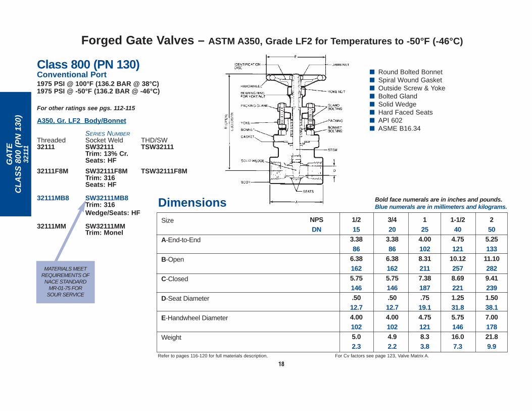
18
MATERIALS MEETREQUIREMENTS OF
NACE STANDARD MR-01-75 FOR
SOUR SERVICE
Size
A-End-to-End
B-Open
C-Closed
D-Seat Diameter
E-Handwheel Diameter
Weight
3/420
3.3886
6.381625.75146.5012.74.001024.92.2
125
4.001028.312117.38187.7519.14.751218.33.8
1/215
3.3886
6.381625.75146.5012.74.001025.02.3
NPSDN
Dimensions Bold face numerals are in inches and pounds.Blue numerals are in millimeters and kilograms.
Refer to pages 116-120 for full materials description. For Cv factors see page 123, Valve Matrix A.
1-1/240
4.75121
10.122578.692211.2531.85.7514616.07.3
250
5.25133
11.102829.412391.5038.17.0017821.89.9
■ Round Bolted Bonnet■ Spiral Wound Gasket■ Outside Screw & Yoke■ Bolted Gland■ Solid Wedge■ Hard Faced Seats■ API 602■ ASME B16.34
Class 800 (PN 130)Conventional Port1975 PSI @ 100°F (136.2 BAR @ 38°C)1975 PSI @ -50°F (136.2 BAR @ -46°C)
For other ratings see pgs. 112-115
A350, Gr. LF2 Body/Bonnet
SERIES NUMBERThreaded Socket Weld THD/SW32111 SW32111 TSW32111
Trim: 13% Cr. Seats: HF
32111F8M SW32111F8M TSW32111F8MTrim: 316 Seats: HF
32111MB8 SW32111MB8Trim: 316Wedge/Seats: HF
32111MM SW32111MMTrim: Monel
Forged Gate Valves – ASTM A350, Grade LF2 for Temperatures to -50°F (-46°C)

GA
TE
CL
AS
S 8
00 (
PN
130
)12
111E
R, 4
1000
19
Size
A-End-to-End
B-Open
C-Closed
D-Seat Diameter
E-Handwheel Diameter
Weight
1/215
3.3886
8.162077.56192.5012.74.001025.92.7
250
5.25133
13.38340
11.692971.5038.17.0017823
10.4
DimensionsBold face numerals are in inches and pounds.Blue numerals are in millimeters and kilograms.
3/420
3.3886
8.162077.56192.5012.74.001025.82.6
125
4.00102
10.282619.36238.7519.14.751219.84.4
1-1/432
4.75121
12.12308
10.722721.2531.85.7514617.78.0
1-1/240
4.75121
12.12308
10.722721.2531.85.7514617.68.0
NPSDN
Refer to pages 116-120 for full materials description. For Cv factors see page 123, Valve Matrix A.
■ Round Bolted Bonnet■ Spiral Wound Gasket■ Outside Screw & Yoke■ Bolted Gland■ Double Packing■ Lantern Ring■ Sealant Injector■ Solid Wedge■ Hard Faced Seats■ API 602■ ASME B16.34
Valve Size Retrofit Bonnet(Series above) Assembly Pkg. No.
1/2, 3/4 41000 04
1 41000 06
1-1/4, 1-1/2 41000 08
2 41000 09
Order by this number:
Class 800 (PN 130)Conventional Port1975 PSI @ 100°F (136.2 BAR @ 38°C)*For other ratings see pgs. 112-115
A105 Body/Bonnet
SERIES NUMBER
Threaded Socket Weld12111ER SW12111ER
Trim: 13% Cr.Seats: HF
EMISSIONS REDUCTION RETROFIT BONNET ASSEMBLY PACKAGES for Field Retrofitting of Vogt Series Nos. 353,363, 373, 12111, SW12111, 12161 and SW12161
*Service temperature will be limited bysealant manufacturer's recommendation.
Forged Gate Valves – Emission Reduction (Including Retrofit Bonnet Assembly)

No Longer Available
Flanged Ends, Class 150 & 300 1/16" R.F.Flanged Ends, Class 600 1/4" R.F.
GA
TE
CL
AS
S 1
50 (
PN
20)
, CL
AS
S 3
00 (
PN
50)
, CL
AS
S 6
00 (
PN
110
)35
3R 3
63R
373
R
20
Class 150 (PN 20)Conventional Port285 PSI @ 100°F (19.7 BAR @ 38°C)
SERIES NUMBER
353R Size 3"BW 353R Sizes 2-1/2", 3"
Trim: Hastelloy Stem & BellowsWedge/Seats: HF
Class 300 (PN 50) Conventional Port740 PSI @ 100°F (51 BAR @ 38°C)
SERIES NUMBER
363R Size 3"BW 363R Sizes 2-1/2", 3"
Trim: Hastelloy Stem & BellowsWedge/Seats: HF
Class 600 (PN 110)Conventional Port1480 PSI @ 100°F (102.1 BAR @ 38°C)
SERIES NUMBER
373R Size 3"BW 373R Sizes 2-1/2", 3"
Trim: Hastelloy Stem & BellowsWedge/Seats: HF
■ Round Bolted Bonnet■ Spiral Wound Gasket■ Outside Screw & Yoke■ Bolted Gland■ Solid Wedge■ Hard Faced Seats■ ASME B16.34■ Five Year Limited Warranty■ Compact Bellows Design
Butt Weld EndsSchedule 40
For Class 150 and 300Schedule 80
For Class 600
380
11.12282
19.84504
17.594472.0050.88.0020359.226.9
Valve flanges conform to ASME Standard B16.5 and end-to-enddimensions conform to ASME Standard B16.10.
For Cv factors see page 123, Valve Matrix A.Refer to pages 116-120 for full materials description.
2-1/265
9.50241
19.84504
17.594472.0050.88.0020349.222.3
2-1/265
13.00330
19.84504
17.594472.0050.88.0020366.530.2
380
14.00356
19.84504
17.594472.0050.88.0020364.329.2
Size
A-End-to-End
B-Open
C-Closed
D-Seat Diameter
E-Handwheel Diameter
Weight
NPSDN
380
11.12282
19.84504
17.594472.0050.88.0020382.537.4
380
14.00356
19.84504
17.594472.0050.88.0020398.544.7
380
8.00203
19.84504
17.594472.0050.88.0020372.432.9
363R 373R BW 353R/363R BW 373R353RDimensions
Zero Fugitive EmissionsTemperature to 425°F (218°C)A105 Body/BonnetFor other ratings see pgs. 112-115
Bold face numerals are in inches and pounds.Blue numerals are in millimeters and kilograms.
Forged Gate Valves – Flexial Design

GA
TE
CL
AS
S 8
00
(PN
130
)13
111,
134
01
21
■ Round Bolted Bonnet■ Spiral Wound Gasket■ Outside Screw & Yoke■ Bolted Gland■ Solid Wedge■ Hard Faced Seats■ API 602■ ASME B16.34
Class 800 (PN 130)Full Port1975 PSI @ 100°F (136.2 BAR @ 38°C)For other ratings see pgs. 112-115
SERIES NUMBER
Body/Bonnet Threaded Socket WeldA105 13111 SW13111
Trim: 13% Cr. Seats: HF
13111FHF SW13111FHFTrim: 13% Cr. Wedge/Seats: HF
13111F8M SW13111F8MTrim: 316Seats: HF
13111MB8 SW13111MB8Trim: 316Wedge/Seats: HF
13111MM SW13111MM– SW13111HF4– SW13111HF5
Trim: Monel
1920 PSI @ 100°F (132.4 BAR @ 38°C)
F316/F316L 13401 SW13401Trim: 316Seats: HF
MATERIALS MEETREQUIREMENTS OF
NACE STANDARD MR-01-75 FOR
SOUR SERVICE
HYDROFLUORIC ACID (HF)ALKYLATION VALVES.
UOPAPPROVED.
Size
A-End-to-End
B-Open
C-Closed
D-Seat Diameter
E-Handwheel Diameter
Weight
1/215
3.3886
6.381625.75146.5012.74.001025.02.3
3/420
4.001028.312117.38187.7519.14.751218.33.8
125
4.381119.562438.382131.0025.45.7514612.15.5
1-1/240
5.25133
11.102829.412391.5038.17.0017822.810.4
250
7.00178
14.09358
11.813002.0050.88.0020342.819.4
NPSDN
Dimensions Bold face numerals are in inches and pounds.Blue numerals are in millimeters and kilograms.
Refer to pages 116-120 for full materials description. For Cv factors see page 123, Valve Matrix B.
Forged Gate Valves

No Longer Available
GA
TE
CL
AS
S 8
00 (
PN
130
)12
111R
, 131
11R
22
■ Round Bolted Bonnet■ Spiral Wound Gasket■ Outside Screw & Yoke■ Bolted Gland■ Solid Wedge■ Hard Faced Seats■ ASME B16.34■ Five Year Limited Warranty■ Compact Bellows Design
Class 800 (PN 130)SERIES NUMBER
Threaded Socket Weld
12111R SW12111R
13111R SW13111R (Full Port)Trim: Hastelloy Stem & BellowsWedge/Seats: HF
Zero Fugitive EmissionsTemperature to 425°F (218°C)A105 Body/Bonnet1975 PSI @ 100°F (136.2 BAR @ 38°C)For other ratings see pgs. 112-115
Size
A-End-to-End
B-Open
C-Closed
D-Seat Diameter
E-Handwheel Diameter
Weight
NPSDN
2-1/265
7.00178
19.84504
17.594472.0050.88.0020357.826.2
250
7.00178
19.84504
17.594472.0050.88.0020357.826.2
DimensionsBold face numerals are in inches and pounds.Blue numerals are in millimeters and kilograms.
Refer to pages 116-120 for full materials description. For Cv factors see page 123, Valve Matrix A or B, as applicable.
12111R 13111R
Forged Gate Valves – Flexial Design

GA
TE
CL
AS
S 8
00 (
PN
130
)12
161
23
Class 800 (PN 130)Conventional Port1975 PSI @ 100°F (136.2 BAR @ 38°C)For other ratings see pgs. 112-115
A105 Body/Bonnet
SERIES NUMBERThreaded Socket Weld12161 SW12161
Trim: 13% Cr. Seats: HF
12161F8M SW12161F8MTrim: 316Seats: HF
12161MM SW12161MMTrim: Monel
■ Round Bolted Bonnet■ Spiral Wound Gasket■ Inside Screw Stem■ Screw Gland■ Solid Wedge■ Hard Faced Seats■ API 602■ ASME B16.34
Dimensions Bold face numerals are in inches and pounds.Blue numerals are in millimeters and kilograms.
Refer to pages 116-120 for full materials description. For Cv factors see page 123, Valve Matrix A.
Size
A-End-to-End
B-Open
C-Closed
D-Seat Diameter
E-Handwheel Diameter
Weight
1/215
3.3870
6.441645.88149.5012.74.001024.82.2
3/420
3.3886
6.441645.88149.5012.74.001024.72.1
125
4.001028.312117.38187.7519.14.751217.93.6
1-1/240
4.75121
10.752739.382381.2531.85.7514616.17.3
250
5.25133
12.25311
10.562681.5038.17.0017823.610.7
NPSDN
1/48
2.7570
6.441645.88149.317.94.001024.32.0
3/810
2.7570
6.441645.88149.317.94.001024.32.0
1-1/432
4.75121
10.752739.382381.2531.85.7514616.47.4
Forged Gate Valves

MATERIALS MEET REQUIREMENTS OF
NACE STANDARD MR-01-75 FOR
SOUR SERVICE
GA
TE
CL
AS
S 8
00 (
PN
130
)28
01
24
■ Welded Bonnet■ Outside Screw & Yoke■ Bolted Gland■ Solid Wedge■ Hard Faced Seats■ API 602■ ASME B16.34
Dimensions Bold face numerals are in inches and pounds.Blue numerals are in millimeters and kilograms.
Refer to pages 116-120 for full materials description. For Cv factors see page 123, Valve Matrix A.
Size
A-End-to-End
B-Open
C-Closed
D-Seat Diameter
E-Handwheel Diameter
Weight
1/215
3.3886
6.501655.88149.5012.74.001023.51.6
3/420
3.3886
6.501655.88149.5012.74.001023.41.5
125
4.001028.312367.38187.7519.14.751216.22.8
1-1/240
4.75121
10.122578.692211.2531.85.7514610.94.9
250
5.25133
11.102829.412391.5038.17.0017816.07.3
NPSDN
1/48
2.7570
6.341615.88149.317.94.001023.01.4
3/810
2.7570
6.341615.88149.317.94.001023.01.4
1-1/432
4.75121
10.122578.692211.2531.85.7514611.55.2
Class 800 (PN 130)Conventional Port1975 PSI @ 100°F (136.2 BAR @ 38°C)For other ratings see pgs. 112-115
A105 Body/Bonnet
SERIES NUMBER
Threaded Socket Weld THD/SW2801 SW2801 TSW2801
Trim: 13% Cr. Seats: HF
2801MM SW2801MMTrim: Monel
2801FHF SW2801FHF TSW2801FHF2801MB6 SW2801MB6
Trim: 13% Cr. Wedge/Seats: HF
2801F8M SW2801F8MTrim: 316 Seats: HF
2801MBS SW2801MBSTrim: MonelWedge: HF
2801MB8 SW2801MB8Trim: 316Wedge/Seats: HF
Forged Gate Valves

GA
TE
CL
AS
S 8
00 (
PN
130
)28
01 2
831,
290
1 29
11, B
T, C
T
25
Size NPS 1/2 3/4 1 1-1/2DN 15 20 25 40
A 4.00 4.00 4.38 5.00102 102 111 127
B 1.69 1.69 2.00 2.3873 73 51 60
C 7.00 7.00 7.50 8.00178 178 190 203
D .47 .47 .69 1.2511.9 11.9 17.5 31.8
E .50 .50 .75 1.2512.7 12.7 19.1 31.8
F 6.50 6.50 8.31 10.12165 165 236 257
G 5.88 5.88 7.38 8.69149 149 187 221
H 4.00 4.00 4.75 5.75102 102 121 146
J .64 .65 .90 1.4716.3 16.5 22.9 37.3
K .75 .75 1.00 1.5019.0 19.0 25.4 38.1
M 1.25 1.25 1.56 2.2531.8 31.8 39.6 57.2
N .81 .81 1.06 1.6920.6 20.6 26.9 42.9
P 1.56 1.56 1.94 2.5639.6 39.6 49.7 65.0
R .97 .97 1.22 1.7224.6 24.6 37.8 43.7
Weight 4.4 4.1 7.3 12.8(Approx.) 2.0 1.9 3.3 5.8
DimensionsClass 800 (PN 130)Conventional PortFor other ratings see pgs. 112-115
A105 BODY/BONNET
1975 PSI @ 100°F (136.2 BAR @ 38°C)
SERIES NUMBER TYPE ENDSCT 2801 Trim: 13% Cr.
Seats: HF
F316, F316L BODY/BONNET1920 PSI @ 100°F (132.4 BAR @ 38°C)
SERIES NUMBERCT 2831 Trim: 316
Seats: HF
A105 BODY/BONNET
1975 PSI @ 100°F (136.2 BAR @ 38°C)
SERIES NUMBER TYPE ENDSCT 2901 Trim: 13% Cr.
Seats: HFCS 2901 Trim: 13% Cr.
Seats: HFCT 2911* Trim: 13% Cr.
Seats: HF
BT 2901 Trim: 13% Cr.Seats: HF
BT 2901MB6 Trim: 13% CrWedge/Seats: HF
}Integrally ReinforcedExtended LengthMale CoupletFemale Socket Weld
Refer to Pages 116-120 for full materials description.For Cv factors see Page 123 Value Matrix E.*Inside Screw Stem valves are not illustrated above; however,OS&Y dimensions shown are applicable, except for theopen/closed dimensions which exceed those shown.
Integrally ReinforcedExtended LengthButt Weld EndFemale Threaded
}}
Bold face numerals are in inches and pounds.Blue numerals are in millimeters and kilograms.
■ Welded Bonnet■ Outside Screw & Yoke■ Bolted Gland■ Solid Wedge■ Hard Faced Seats■ API 602■ ASME B16.34
Integral MaleCoupletFemaleThreaded
MATERIALS MEETREQUIREMENTS OF
NACE STANDARD MR-01-75 FOR
SOUR SERVICE
Forged Gate Valves – Extended Body Valves

GA
TE
CL
AS
S 8
00 (
PN
130
)28
01
2811
, 283
1, S
T, T
T, S
S
26
Size NPS 1/2 3/4 1 1-1/2DN 15 20 25 40
A 4.00 4.00 4.38 5.00102 102 111 127
B 1.69 1.69 2.00 2.3873 73 51 60
D .47 .47 .69 1.2511.9 11.9 17.5 31.8
F 6.50 6.50 8.31 10.12165 165 236 257
G 5.88 5.88 7.38 8.69149 149 187 221
H 4.00 4.00 4.75 5.75102 102 121 146
J .64 .65 .90 1.4716.3 16.5 22.9 37.3
L .84 1.05 1.32 1.9021.3 26.7 33.5 48.3
M 1.25 1.25 1.56 2.2531.8 31.8 39.6 57.2
Weight 4.4 4.1 7.3 12.8(Approx.) 2.0 1.9 3.3 5.8
Dimensions
Bold face numerals are in inches and pounds.Blue numerals are in millimeters and kilograms.
■ Welded Bonnet■ Outside Screw & Yoke■ Bolted Gland■ Solid Wedge■ Hard Faced Seats■ API 602■ ASME B16.34
Class 800 (PN 130)Conventional PortFor other ratings see pgs. 112-115
}}
A105 BODY/BONNET
1975 PSI @ 100°F (136.2 BAR @ 38°C)SERIES NUMBER TYPE ENDS
TT 2801 Trim: 13% Cr.Seat: HF
TT 2801MM Trim: MonelTT 2801F8M Trim: 316
Seats: HFTT 2801MB8 Trim: 316
Wedge/Seats: HFTT 2801MB6 Trim: 13% Cr.
Wedge/Seats: HFTT 2811* Trim: 13% Cr.
Seat: HF
F316/F316L BODY/BONNET1920 PSI @ 100°F (132.4 BAR @ 38°C)TT 2831 Trim: 316
Seat: HF
A105 BODY/BONNET
1975 PSI @ 100°F (136.2 BAR @ 38°C)
SERIES NUMBER TYPE ENDSST 2801 Trim: 13% Cr.
Seats: HFST 2801F8M Trim: 316
Seats: HFST 2801MM Trim: Monel ST 2801FHF Trim: 13% Cr.
Wedge/Seats: HFST 2801MB8 Trim: 316
Wedge/Seats: HFST 2801MB6 Trim: 13% Cr.
Wedge/Seats: HFSS 2801 Trim: 13% Cr.
Seats: HFSS 2801MB6 Trim: 13% Cr.
Wedge/Seats: HF
F316/F316L BODY/BONNET1920 PSI @ 100°F (132.4 BAR @ 38°C)ST 2831 Trim: 316
Seats: HF
}
}
Refer to Pages 116-120 for full materials description.For Cv factors see Page 123 Value Matrix E.*Inside Screw Stem valves are not illustrated above; however,OS&Y dimensions shown are applicable, except for the open/closeddimensions which exceed those shown.1/2" TT 2801, TT 2811 and TT 2831 male threaded valves are notcovered under API 602 rules.
IntegralMale Socket WeldFemaleThreaded
Integral Male SocketWeld Female SocketWeld (Not illus.)
Integral Male SocketWeld Female Threaded(See above illus.)
IntegralMaleThreadedFemaleThreaded
MATERIALS MEETREQUIREMENTS
OF NACESTANDARD
MR-01-75 FOR SOUR SERVICE
MATERIALS MEET REQUIREMENTS OF NACE STANDARD MR-01-75
FOR SOUR SERVICE
Forged Gate Valves – Extended Body Valves

GA
TE
CL
AS
S 8
00 (
PN
130
)C
T 1
2111
, BT
121
11, B
S 1
2111
27
■ Bolted Bonnet■ Outside Screw &Yoke■ Bolted Gland■ Solid Wedge■ Hard Faced Seats■ API 602■ ASME B16.34
Class 800 (PN 130)Conventional PortFor other ratings see pgs. 112-115
A105 Body/Bonnet1975 PSI @ 100°F (136.2 BAR @ 38°C)
SERIES NUMBER TYPE ENDSCT 12111 Trim: 13% Cr. Integrally Reinforced
Seats: HF Extended LengthCT 12111MB8 Trim: 316 Male Couplet
Wedge/Seats: HF Female Threaded}
Size NPS 1/2 3/4 1 1-1/2DN 15 20 25 40
B 1.97 1.97 2.09 2.7250 50 53 69
C 7.00 7.00 7.50 8.00178 178 190 203
E .50 .50 .75 1.2512.7 12.7 19.1 31.8
F 6.38 6.38 8.31 10.12162 162 236 257
G 5.75 5.75 7.38 8.69146 146 187 221
H 4.00 4.00 4.75 5.75102 102 121 146
K .75 .75 1.00 1.5019.1 19.1 25.4 38.1
P 1.56 1.56 1.94 2.5639.6 39.6 49.7 65.0
R .97 .97 1.22 1.7224.6 24.6 37.8 43.7
Weight 6.0 5.6 9.4 16.5(Approx.) 2.7 2.5 4.3 7.5
Dimensions
Bold face numerals are in inches and pounds.Blue numerals are in millimeters and kilograms.
MATERIALS MEET REQUIREMENTSOF NACE STANDARD MR-01-75
FOR SOUR SERVICE
MATERIALS MEETREQUIREMENTS OF
NACE STANDARD MR-01-75 FOR
SOUR SERVICE
SERIES NUMBER TYPE ENDSBT 12111 Trim: 13% Cr. Integrally Reinforced
Seats: HF Extended LengthBT 12111MB8 Trim: 316 Male Butt Weld Couplet
Wedge/Seats: HF Female Threaded
BS 12111 Trim: 13% Cr. Integrally ReinforcedSeats: HF Extended Length
Male Butt Weld CoupletFemale Socket Weld(not illustrated)
}}
Refer to Pages 116-120 for full materials description. For Cv factorssee Page 123 Value Matrix F.Can be disassembled for post weld heat treat procedure afterinstallation if gate orientation is marked and maintained in same valvewhen reassembled.Note: The valves illustrated on this page do not require an interfacingfitting. The valve can be welded directly to a pipe header or vessel. Valve designs similar to the above are available without the 0.38"integral backing ring.
Forged Gate Valves – Extended Body Valves

GA
TE
CL
AS
S 8
00 (
PN
130
)S
T12
111
28
Class 800 (PN 130)Conventional PortFor other ratings see pgs. 112-115
A105 Body/Bonnet
1975 PSI @ 100°F (136.2 BAR @ 38°C)
Refer to Pages 116-120 for full materials description. For Cv factorssee Page 123 Valve Matrix F.Can be disassembled for post weld heat treat procedure afterinstallation if gate orientation is marked and maintained in same valvewhen reassembled.
SERIES NUMBER Type EndsST 12111 Trim: 13% Cr.
Seats: HF
ST 12111MB8 Trim: 316Wedge/Seats: HF
ST 12111MB6 Trim: 13% Cr.Wedge/Seats: HF
} IntegralMaleSocket WeldFemaleThreaded
Size NPS 1/2 3/4 1 1-1/2DN 15 20 25 40
A 6.50 7.00 7.50 8.00165 178 191 203
B 1.97 1.97 2.09 2.7250 50 53 69
D .47 .47 .75 1.2511.9 11.9 19.1 31.8
F 6.38 6.38 8.31 10.12162 162 211 257
G 5.75 5.75 7.38 8.69146 146 187 221
H 4.00 4.00 4.75 5.75102 102 121 146
J .64 .75 1.00 1.5016.3 19.1 25.4 38.1
L .84 1.05 1.32 1.9021 26.7 34 48
M 1.56 1.56 1.94 2.5639.6 39.6 49.7 65.0
Weight 5.7 4.1 7.3 16.5(Approx.) 2.6 1.9 3.3 7.5
Dimensions
Bold face numerals are in inches and pounds.Blue numerals are in millimeters and kilograms.
■ Bolted Bonnet■ Outside Screw & Yoke■ Bolted Gland■ Solid Wedge■ Hard Faced Seats■ API 602■ ASME B16.34
MATERIALS MEETREQUIREMENTS OF
NACE STANDARD MR-01-75 FOR
SOUR SERVICE
Forged Gate Valves – Extended Body Valves
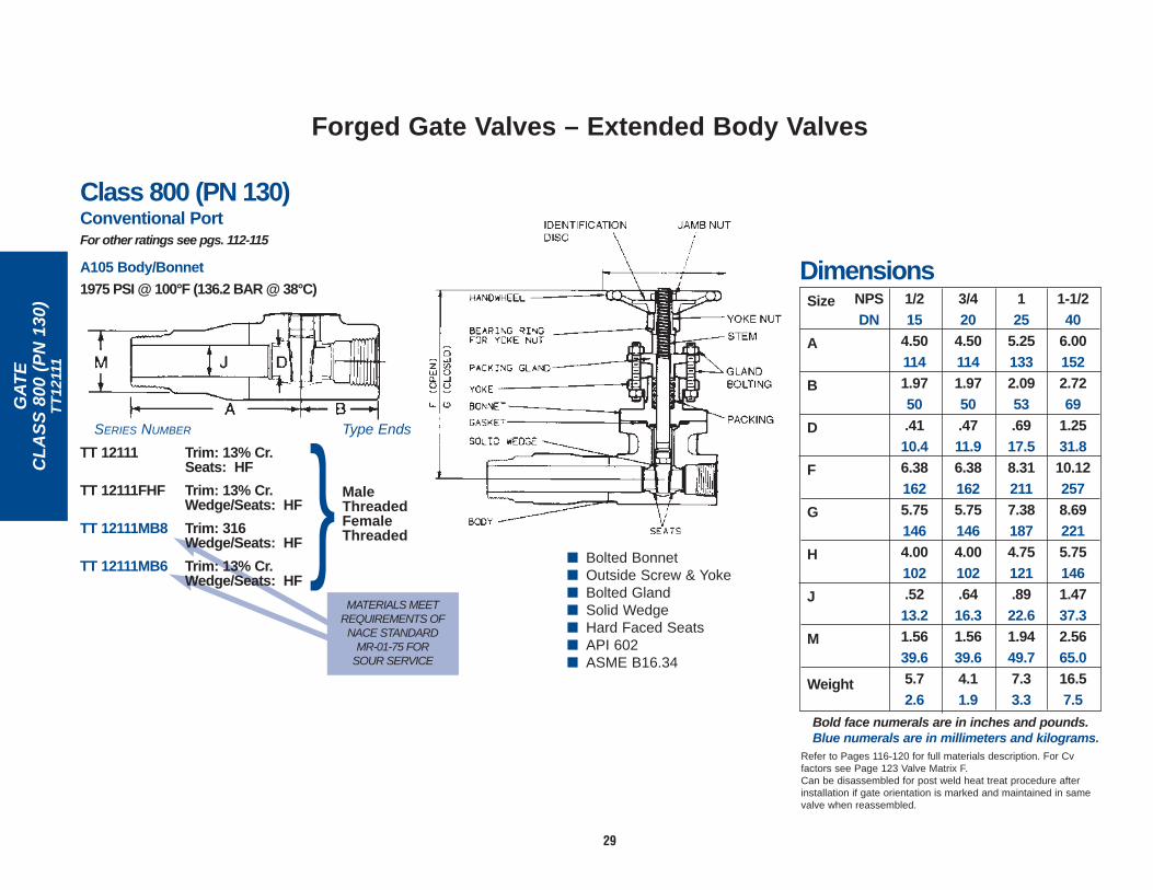
GA
TE
CL
AS
S 8
00 (
PN
130
)T
T12
111
29
Dimensions
Refer to Pages 116-120 for full materials description. For Cvfactors see Page 123 Valve Matrix F.Can be disassembled for post weld heat treat procedure afterinstallation if gate orientation is marked and maintained in samevalve when reassembled.
NPSDN
1-1/240
6.001522.7269
1.2531.810.122578.692215.751461.4737.32.5665.016.57.5
125
5.251332.0953.6917.58.312117.381874.75121.8922.61.9449.77.33.3
3/420
4.501141.9750.4711.96.381625.751464.00102.6416.31.5639.64.11.9
1/215
4.501141.9750.4110.46.381625.751464.00102.5213.21.5639.65.72.6
Size
A
B
D
F
G
H
J
M
Weight
Class 800 (PN 130)Conventional PortFor other ratings see pgs. 112-115
A105 Body/Bonnet
1975 PSI @ 100°F (136.2 BAR @ 38°C)
MATERIALS MEETREQUIREMENTS OF
NACE STANDARD MR-01-75 FOR
SOUR SERVICE
■ Bolted Bonnet■ Outside Screw & Yoke■ Bolted Gland■ Solid Wedge■ Hard Faced Seats■ API 602■ ASME B16.34
SERIES NUMBER Type Ends
TT 12111 Trim: 13% Cr.Seats: HF
TT 12111FHF Trim: 13% Cr.Wedge/Seats: HF
TT 12111MB8 Trim: 316Wedge/Seats: HF
TT 12111MB6 Trim: 13% Cr.Wedge/Seats: HF
} MaleThreadedFemaleThreaded
Bold face numerals are in inches and pounds.Blue numerals are in millimeters and kilograms.
Forged Gate Valves – Extended Body Valves

GA
TE
CL
AS
S 8
00 (
PN
130
)28
31
30
Size
A-End-to-End
B-Open
C-Closed
D-Seat Diameter
E-Handwheel Diameter
Weight
1/215
3.3886
6.501655.88149.5012.74.001023.51.6
3/420
3.3886
6.501655.88149.5012.74.001023.41.5
125
4.001028.312367.38187.7519.14.751216.22.8
1-1/240
4.75121
10.122578.692211.2531.85.7514610.94.9
250
5.25133
11.102829.412391.5038.17.0017816.07.3
NPSDN
Dimensions
+ Valves contain TEFLON—maximum temperature 500°F.Refer to pages 116-120 for full materials description.
For Cv factors see page 123, Valve Matrix A.
Class 800 (PN 130)Conventional Port1920 PSI @ 100°F (132.4 BAR @ 38°C)For other ratings see pgs. 112-115
F316/F316L Body/Bonnet
SERIES NUMBER
Threaded Socket Weld2831 SW 28312831T+ SW 2831T+
Trim: 316 Seats: HF
■ Welded Bonnet■ Outside Screw & Yoke■ Bolted Gland■ Solid Wedge■ Hard Faced Seats■ API 602■ ASME B16.34
Bold face numerals are in inches and pounds.Blue numerals are in millimeters and kilograms.
Forged Gate Valves

GA
TE
CL
AS
S 8
00 (
PN
130
)28
11
31
Forged Gate Valves
Class 800 (PN 130)Conventional Port1975 PSI @ 100°F (136.2 BAR @ 38°C)For other ratings see pgs. 112-115
A105 Body/Bonnet
SERIES NUMBERThreaded Socket Weld THD/SW2811 SW 2811 TSW2811
Trim: 13% Cr. Seats: HF
2811FHF SW2811FHF Trim: 13% Cr. Wedge/Seats: HF
Dimensions Bold face numerals are in inches and pounds.Blue numerals are in millimeters and kilograms.
Refer to pages 116-120 for full materials description. For Cv factors see page 123, Valve Matrix A.
Size
A-End-to-End
B-Open
C-Closed
D-Seat Diameter
E-Handwheel Diameter
Weight
3/420
3.3886
6.621686.00152.5012.74.001023.11.4
125
4.001028.382137.44189.751914.751216.12.8
1-1/432
4.75121
10.812759.382381.2531.85.7514611.65.3
1-1/240
4.75121
10.812759.382381.2531.85.7514611.05.0
250
5.25133
12.12308
10.562681.5038.17.0017818.58.4
NPSDN
1/215
3.3870
6.621686.00152.5012.74.001023.21.5
■ Welded Bonnet■ Inside Screw Stem■ Screw Gland■ Solid Wedge■ Hard Faced Seats■ API 602■ ASME B16.34

GA
TE
CL
AS
S 8
00 (
PN
130
)59
851,
599
51
Forged Gate Valves
■ Union Bonnet■ Spiral Wound Gasket■ Inside Screw Stem■ Screw Gland■ Solid Wedge■ Hard Faced Seats■ API 602■ ASME B16.34
Size
A-End-to-End
B-Open
C-Closed
D-Seat Diameter
E-Handwheel Diameter
Weight
1/215
3.3870
6.441645.88149.5012.74.001023.91.8
3/420
3.3886
6.441645.88149.5012.74.001023.71.7
125
4.001028.382137.44189.7519.14.751216.93.1
1-1/240
4.75121
10.692729.252351.2531.85.7514613.66.2
250
5.25133
12.25311
10.562391.5038.17.0017822.310.1
NPSDN
Dimensions Bold face numerals are in inches and pounds.Blue numerals are in millimeters and kilograms.
+ Valves contain TEFLON—maximum temperature 500°F.Refer to pages 116-120 for full materials description.
For Cv factors see page 123, Valve Matrix A.
1/48
2.7570
6.441645.88149.317.94.001023.71.7
3/810
2.7570
6.441645.88149.317.94.001023.71.7
1-1/432
4.75121
10.692729.252351.2531.85.7514614.26.4
Class 800 (PN 130)Conventional Port1975 PSI @ 100°F (136.2 BAR @ 38°C)For other ratings see pgs. 112-115
SERIES NUMBER
Body/Bonnet Threaded Socket WeldA105 59851 SW59851
Trim: 13% Cr.Seats: HF
59851F8M SW59851F8M Trim: 316Seats: HF
59851MM SW59851MM Trim: Monel
59851MBS SW59851MBSTrim: MonelWedge: HF
1920 PSI @ 100°F (132.4 BAR @ 38°C)
F316/ 59951F316L (Sizes 1/4-1 Only)
59951T+
(Sizes 1/4-1 Only)Trim: 316Seats: HF
MATERIALS MEETREQUIREMENTS OF
NACE STANDARD MR-01-75 FOR
SOUR SERVICE
32
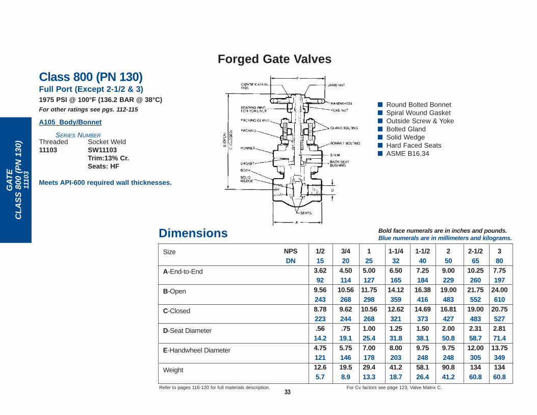
GA
TE
CL
AS
S 8
00 (
PN
130
)11
103
33
Forged Gate Valves
Dimensions Bold face numerals are in inches and pounds.Blue numerals are in millimeters and kilograms.
Refer to pages 116-120 for full materials description. For Cv factors see page 123, Valve Matrix C.
Size
A-End-to-End
B-Open
C-Closed
D-Seat Diameter
E-Handwheel Diameter
Weight
1/215
3.6292
9.562438.78223.5614.24.7512112.65.7
3/420
4.50114
10.562689.62244.7519.15.7514619.58.9
125
5.00127
11.75298
10.562681.0025.47.0017829.413.3
1-1/240
7.25184
16.38416
14.693731.5038.19.7524858.126.4
250
9.00229
19.00483
16.814272.0050.89.7524890.841.2
NPSDN
2-1/265
10.25260
21.75552
19.004832.3158.712.0030513460.8
380
7.75197
24.00610
20.755272.8171.413.7534913460.8
1-1/432
6.50165
14.12359
12.623211.2531.88.0020341.218.7
■ Round Bolted Bonnet■ Spiral Wound Gasket■ Outside Screw & Yoke■ Bolted Gland■ Solid Wedge■ Hard Faced Seats■ ASME B16.34
Class 800 (PN 130)Full Port (Except 2-1/2 & 3)1975 PSI @ 100°F (136.2 BAR @ 38°C)For other ratings see pgs. 112-115
A105 Body/Bonnet
SERIES NUMBERThreaded Socket Weld11103 SW11103
Trim:13% Cr. Seats: HF
Meets API-600 required wall thicknesses.

GA
TE
CL
AS
S 1
500
(PN
260
)15
373
34
Forged Gate Valves
Valve flanges conform to ASME Standard B16.5 and end-to-enddimensions conform to ASME Standard B16.10.
For Cv factors see page 123, Valve Matrix A.Refer to pages 116-120 for full materials description.
DimensionsBold face numerals are in inches and pounds.Blue numerals are in millimeters and kilograms.
Size
A-End-to-End
B-Open
C-Closed
D-Seat Diameter
E-Handwheel Diameter
Weight
NPSDN
1/215
8.502167.472436.88175.5012.74.7512117.27.8
3/420
9.002297.472436.88175.5012.74.7512120.19.1
125
10.002549.692468.78268.7519.17.0017834.615.7
1-1/240
12.00305
11.382899.972531.2531.88.0020348.522.0
250
14.50368
13.84351
12.163091.5038.19.7524894.142.7
Class 1500 (Conventional Port):
■ Round Bolted Bonnet■ Spiral Wound Gasket■ Outside Screw & Yoke■ Bolted Gland■ Solid Wedge■ Hard Faced Seats■ Integral Hard Faced Seat■ ASME B16.34
Class 1500 (PN 260)API 602/ASME B16.34Conventional Port3705 PSI @ 100°F (255.5 BAR @ 38°C)For other ratings see pgs. 112-115
A105 Body/Bonnet
SERIES NUMBER15373 Trim: 13% Cr.
Seats: HF
15373FHF Trim: 13% Cr. Wedge/Seats: HF
RING JOINT FACESRJ15373 Trim: 13% Cr.
Seats: HF
RJ15373FHF Trim: 13% Cr. Wedge/Seats: HF
Flanged Ends 1/4" R.F.

GA
TE
CL
AS
S 1
500
(PN
260
)11
603,
116
83
35
Forged Gate Valves
DimensionsBold face numerals are in inches and pounds.Blue numerals are in millimeters and kilograms.
Size
A-End-to-End
B-Open
C-Closed
D-Seat Diameter
E-Handwheel Diameter
Weight
1/215
8.50216
12.12308
11.38289.5614.27.0017843.319.7
3/420
9.00229
14.00356
12.94329.7519.17.0017855.025.0
125
10.00254
15.62397
14.50368.8822.48.0020376.034.5
1-1/240
12.00305
20.12511
18.384671.3835.012.00305
117.853.5
250
14.50368
23.56598
21.255402.0050.813.75349230
104.4
NPSDN
1-1/432
11.00279
17.75451
16.444181.1228.49.7524892.041.8
Class 1500 (Full Port):
Valve flanges conform to ASME Standard B16.5 and end-to-enddimensions conform to ASME Standard B16.10.
For Cv factors see page 123, Valve Matrix G.Refer to pages 116-120 for full materials description.
Class 1500 (PN 260)ASME B16.34Full Port3705 PSI @ 100°F (255.5 BAR @ 38°C)For other ratings see pgs. 112-115
A105 Body/Bonnet
SERIES NUMBER11603 1/4" Raised Faces 11683 Ring Joint Faces
Trim: 13% Cr. Seats: HF
Meets API-600 required wall thicknesses.
■ Round Bolted Bonnet■ Spiral Wound Gasket■ Outside Screw & Yoke■ Bolted Gland■ Solid Wedge■ Hard Faced Seats■ Integral Hard Faced Seat■ ASME B16.34
Flanged Ends 1/4" R.F.

GA
TE
CL
AS
S 1
500
(PN
260
)10
33, 1
043
36
Forged Gate Valves
Size
A-End-to-End
B-Open
C-Closed
D-Seat Diameter
E-Handwheel Diameter
Weight
250
9.50241
21.00533
18.694752.0050.812.00305
116.352.8
Dimensions Bold face numerals are in inches and pounds.Blue numerals are in millimeters and kilograms.
Refer to pages 116-120 for full materials description. For Cv factors see page 123, Valve Matrix G.
3/420
5.00127
11.69297
10.75273.751917.0017829.913.6
125
6.50165
14.06357
12.94329.8822.38.0020344.420.2
1-1/432
7.25184
16.38416
14.883781.2531.89.7524863.028.6
1-1/240
9.00229
18.75476
17.124351.3835.19.7524810045.4
NPSDN
1/215
4.50114
10.75273
10.00254.5614.25.7514621.99.9
■ Round Bolted Bonnet■ Flat Gasket Joint or
Ring Joint Gasket■ Outside Screw & Yoke■ Bolted Gland■ Solid Wedge■ Hard Faced Seats■ ASME B16.34
Class 1500 (PN 260)Full Port3705 PSI @ 100°F (255.5 BAR @ 38°C)For other ratings see pgs. 112-115
A105 Body/Bonnet
SERIES NUMBERThreaded Socket Weld1033 SW10331043 SW1043 Ring Joint Gasket Bonnet
(Not illustrated)Trim: 13% Cr. Seats: HF
Meets API-600 required wall thicknesses.

GA
TE
CL
AS
S 1
500
(PN
260
)15
111,
153
21, 1
5401
37
Forged Gate Valves
MATERIALS MEETREQUIREMENTS OF
NACE STANDARD MR-01-75 FOR
SOUR SERVICE
Dimensions Bold face numerals are in inches and pounds.Blue numerals are in millimeters and kilograms.
Refer to pages 116-120 for full materials description. For Cv factors see page 123, Valve Matrix A.
Size
A-End-to-End
B-Open
C-Closed
D-Seat Diameter
E-Handwheel Diameter
Weight
3/420
4.001027.471906.88175.5012.74.751218.43.8
125
4.751219.692468.78223.7519.17.0017818.08.2
1-1/432
5.25133
11.382899.972531.2531.88.0020327.012.3
1-1/240
5.25133
11.382899.972531.2531.88.0020326.912.2
250
7.00178
13.84351
12.163091.5038.19.7524848.221.9
NPSDN
1/215
4.001027.471906.88175.5012.74.751218.53.9
■ Round Bolted Bonnet■ Spiral Wound Gasket ■ Outside Screw & Yoke■ Bolted Gland■ Solid Wedge■ Hard Faced Seats■ API 602■ ASME B16.34
Class 1500 (PN 260)Conventional Port3705 PSI @ 100°F (255.5 BAR @ 38°C)
For other ratings see pgs. 112-115SERIES NUMBER
Body/Bonnet Threaded Socket WeldA105 15111 SW15111
Trim: 13% Cr.Seats: HF
15111F8M SW15111F8MTrim: 316Seats: HF
15111FHF SW15111FHFTrim: 13% Cr. Wedge/Seats: HF
15111MB6 SW15111MB6Trim: 13% Cr. Wedge/Seats: HF
15111MBS SW15111MBSTrim: MonelWedge: HF
15111MB8 SW15111MB8Trim: 316Wedge/Seats: HF
F11 CL2 3750 PSI @ 100°F (258.6 BAR @ 38°C)15321 SW15321
Trim: 13% Cr. Seats: HF
F316/ 3600 PSI @ 100°F (248.3 BAR @ 38°C)F316L 15401 SW15401
Sizes 1/2-2 (No 1-1/4)Trim: 316Seats: HF
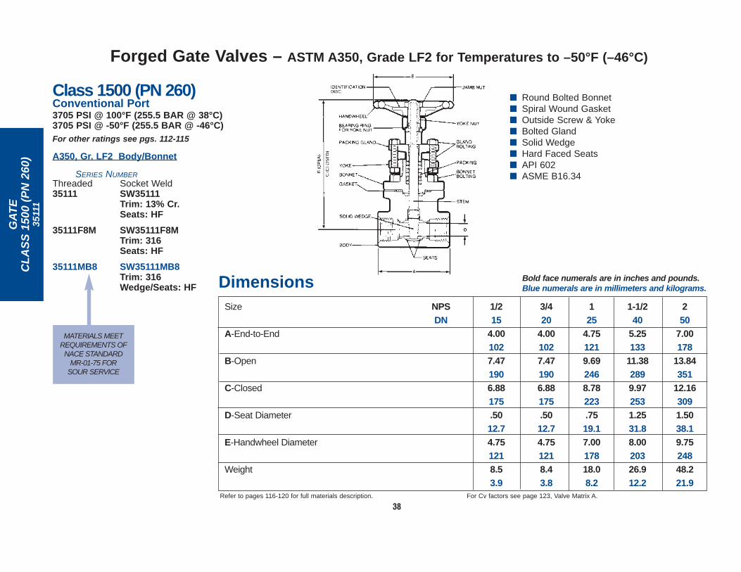
GA
TE
CL
AS
S 1
500
(PN
260
)35
111
38
Size
A-End-to-End
B-Open
C-Closed
D-Seat Diameter
E-Handwheel Diameter
Weight
NPSDN
Dimensions Bold face numerals are in inches and pounds.Blue numerals are in millimeters and kilograms.
Refer to pages 116-120 for full materials description. For Cv factors see page 123, Valve Matrix A.
1/215
4.001027.471906.88175.5012.74.751218.53.9
3/420
4.001027.471906.88175.5012.74.751218.43.8
125
4.751219.692468.78223.7519.17.0017818.08.2
1-1/240
5.25133
11.382899.972531.2531.88.0020326.912.2
250
7.00178
13.84351
12.163091.5038.19.7524848.221.9
■ Round Bolted Bonnet■ Spiral Wound Gasket■ Outside Screw & Yoke■ Bolted Gland■ Solid Wedge■ Hard Faced Seats■ API 602■ ASME B16.34
Class 1500 (PN 260)Conventional Port3705 PSI @ 100°F (255.5 BAR @ 38°C)3705 PSI @ -50°F (255.5 BAR @ -46°C)For other ratings see pgs. 112-115
A350, Gr. LF2 Body/Bonnet
SERIES NUMBERThreaded Socket Weld35111 SW35111
Trim: 13% Cr. Seats: HF
35111F8M SW35111F8MTrim: 316Seats: HF
35111MB8 SW35111MB8Trim: 316 Wedge/Seats: HF
MATERIALS MEETREQUIREMENTS OF
NACE STANDARD MR-01-75 FOR
SOUR SERVICE
Forged Gate Valves – ASTM A350, Grade LF2 for Temperatures to –50°F (–46°C)

GA
TE
CL
AS
S 1
500
(PN
260
)16
111
39
Forged Gate Valves
■ Round Bolted Bonnet■ Spiral Wound Gasket■ Outside Screw & Yoke■ Bolted Gland■ Solid Wedge■ Hard Faced Seats■ API 602■ ASME B16.34
Class 1500 (PN 260)Full Port3705 PSI @ 100°F (255.5 BAR @ 38°C)For other ratings see pgs. 112-115
A105 Body/Bonnet
SERIES NUMBER
Threaded Socket Weld16111 SW16111
Trim: 13% Cr. Seats: HF
Size
A-End-to-End
B-Open
C-Closed
D-Seat Diameter
E-Handwheel Diameter
Weight
NPSDN
Dimensions Bold face numerals are in inches and pounds.Blue numerals are in millimeters and kilograms.
Refer to pages 116-120 for full materials description. For Cv factors see page 123, Valve Matrix B.
1/215
4.001027.471906.88175.5012.74.751218.53.9
3/420
4.751219.692468.78223.7519.17.0017817.57.9
125
5.25133
11.122829.972531.0025.48.0020328.512.9
1-1/240
7.00178
13.84351
12.163091.5038.19.7524848.221.9
1-1/432
5.25133
11.382899.972531.2531.88.0020327.012.3

GA
TE
CL
AS
S 1
500
(PN
260
)15
801,
158
31
40
Forged Gate Valves
■ Welded Bonnet■ Outside Screw & Yoke■ Bolted Gland■ Solid Wedge■ Hard Faced Seats■ API 602■ ASME B16.34
Dimensions Bold face numerals are in inches and pounds.Blue numerals are in millimeters and kilograms.
Size
A-End-to-End
B-Open
C-Closed
D-Seat Diameter
E-Handwheel Diameter
Weight
3/420
4.001027.531916.88175.5012.74.751217.23.3
125
4.751219.692468.78223.7519.17.0017813.56.1
1-1/432
5.25133
11.412909.972531.2531.88.0020318.28.3
1-1/240
5.25133
11.412909.972531.2531.88.0020317.57.9
250
7.00178
13.84352
12.163091.5038.19.7524837.016.8
NPSDN
1/215
4.001027.531916.88175.5012.74.751217.43.4
Refer to pages 116-120 for full materials description. For Cv factors see page 123, Valve Matrix A.
MATERIALS MEETREQUIREMENTS OF
NACE STANDARD MR-01-75 FOR
SOUR SERVICE
Class 1500 (PN 260)Conventional Port3705 PSI @ 100°F (255.5 BAR @ 38°C)For other ratings see pgs. 112-115
A105 Body/Bonnet
SERIES NUMBER
Threaded Socket Weld15801 SW15801
Trim: 13% Cr. Seats: HF
15801FHF SW15801FHFTrim: 13% Cr. Wedge/Seats: HF
15801MM SW15801MMTrim: Monel
15801MB8 SW15801MB8Trim: 316 Wedge/Seats: HF
15801MBS SW15801MBSTrim: MonelWedge: HF
F316/F316L
3600 PSI @ 100°F (248.3 BAR @ 38°C)15831 SW15831
Trim: 316Seats: HF

GA
TE
CL
AS
S 1
500
(PN
260
)S
T 1
5801
41
Forged Gate Valves – Extended Body Valves
■ Welded Bonnet■ Outside Screw & Yoke■ Bolted Gland■ Solid Wedge■ Hard Faced Seats■ API 602■ ASME B16.34
Class 1500 (PN 260)Conventional PortFor other ratings see pgs. 112-115
A105 BODY/BONNET
3705 PSI @ 100°F (255.5 BAR @ 38°C)
SERIES NUMBER TYPE ENDS
ST 15801 Trim: 13% Cr.Seats: HF
ST 15801F8M Trim: 316Seats: HF
Dimensions
Refer to Pages 116-120 for full materials description.For Cv factors see Page 123 Valve Matrix A.
NPSDN
125
5.381372.3860.7519.19.692468.782237.001781.1228.41.3233.52.2557.214.06.4
3/420
4.691192.0051.5012.77.531916.881754.75121.6917.51.0526.71.5639.68.53.9
1/215
4.691192.0051.5012.77.531916.881754.75121.6917.5.8421.31.5639.68.74.0
Size
A
B
D
F
G
H
J
L
M
Weight
Integral MaleSocket WeldFemale Threaded
}

Class 2500 (PN 420)Full Port6250 PSI @ 100°F (431.0 BAR @ 38°C)For other ratings see pgs. 112-115
SERIES NUMBER
Body/Bonnet Threaded Socket WeldA105 66703 SW66703
Trim: 13% Cr. Wedge/Seats: HF
F11, Cl. 2 66713 SW66713 (1-1/4% Cr.) Trim: 13% Cr.
Wedge/Seats: HF
F22, Cl. 3 66773 SW66773(2-1/4% Cr.) Trim: 13% Cr.
Wedge/Seats: HF
GA
TE
CL
AS
S 2
500
(PN
420
)66
703,
667
13, 6
6773
42
Forged Gate Valves
■ Welded Bonnet■ Outside Screw & Yoke■ Bolted Gland■ Solid Hard Faced Wedge■ Hard Faced Seats■ ASME B16.34 LTD. Pressure Class
Size
A-End-to-End
B-Open
C-Closed
D-Seat Diameter
E-Handwheel Diameter
Weight
1/215
4.001028.812248.19208.4110.45.751468.73.9
3/420
5.12130
11.00279
10.00254.7519.18.0020321.09.5
125
5.12130
11.00279
10.00254.7519.18.0020320.19.1
1-1/240
8.50216
15.88403
14.063571.5038.112.0030565.729.8
250
8.50216
15.88403
14.063571.5038.112.0030565.529.7
NPSDN
Dimensions Bold face numerals are in inches and pounds.Blue numerals are in millimeters and kilograms.
Refer to pages 116-120 for full materials description. For Cv factors see page 123, Valve Matrix H.

GA
TE
CL
AS
S 8
00 (
PN
130
), C
LA
SS
150
0 (P
N 2
60)
3211
1, 3
5111
43
Forged Gate Valves – ASTM A350, GRADE LF2 Class 800 and Class 1500 ValvesFOR APPLICATIONS WHERE TEMPERATURES TO –50°F (–46°C) ARE THE RULE NOT THE EXCEPTION!
PRESSURE-TEMPERATURE RATINGS
Service Temperature
(°F)
–50 to 100
200
300
400
500
600
700
800
CLASS 800ASTM A350, GR. LF2
(1) (2)PSI
1975
1800
1750
1690
1595
1460
1420
1100
CLASS 1500ASTM A350, GR. LF2
(1) (2)PSI
3705
3375
3280
3170
2995
2735
2665
2060
PRESSURE-TEMPERATURE RATINGS
Service Temperature
(°C)
–46 to 38
50
100
150
200
250
300
400
425
PN 130 (CLASS 800)ASTM A350, GR. LF2
(1) (2)BAR
136.2
133.5
123.7
120.6
116.9
111.2
103.3
92.1
76.9
PN 260 (CLASS 1500)ASTM A350, GR. LF2
(1) (2)BAR
255.5
250.5
232.0
226.0
219.2
208.8
193.6
172.5
144.0
■ Traceable Parts From Stock
■ Machined Parts HeatTreated to ASTM A350,Grade LF2
■ Charpy Impact Tested■ Verified Strength
and Toughness■ Flexible Graphite
Packing■ Flexible Graphite
Filled Gasket■ API 602 ■ ASME B16.34
(1) Ratings are in accordance with ASME/ANSI B16.34-96.(2) Permissible but not recommended for prolonged use above 800°F
(427°C).
*NOTE: Other Vogtvalves are alsooffered in A350-LF2construction. Seeindividual pages ofVV200 Catalog.
For Cv factors see page 123, Valve Matrix A.Refer to pages 116-120 for full materials description.
MATERIALSMEET
REQUIREMENTSOF NACE
STANDARD MR-01-75 FOR
SOUR SERVICE
Class 800 (PN 130)* Class 1500 (PN 260)* Conventional Port Conventional Port1975 PSI @ 100°F (136.2 BAR @ 38°C) 3705 PSI @ 100°F (255.5 BAR @ 38°C)
A350, GR. LF2 Body/Bonnet A350, GR. LF2 Body/Bonnet
SERIES NUMBER SERIES NUMBER
Threaded Socket Weld Threaded Socket WeldSize 1/2”-2” Size 1/2”-2”
32111 SW32111 35111 SW35111Trim: 13% Cr. Trim: 13% Cr.Seats: HF Seats: HF
32111F8M SW32111F8M 35111F8M SW35111F8MTrim: 316 Trim: 316Seats: HF Seats: HF
32111MB8 SW32111MB8 35111MB8 SW35111MB8Trim: 316 Trim: 316Wedge/Seats: HF Wedge/Seats: HF
See Dimensions on Pg. 18 See Dimensions on Pg. 38

NU
CL
EA
RG
AT
E, G
LO
BE
& C
HE
CK
Forged Nuclear Valves – Nuclear Gate, Globe and Check
Vogt Valves forNuclear ServiceVogt offers Class 1, 2 or 3 gate,
globe and check valves of
forged carbon and stainless
steel in 1/4” to 2” sizes, in
ASME Section III "N" stamp
construction. Pressure classes
150, 300, 600, 900 and 1500
are offered. Unlike many others,
Vogt designs, manufactures and
tests all pressure boundary
parts at one location to insure
complete satisfaction of
customer and N-stamp code
requirements.
The chart shows dimensions of
popular Vogt nuclear valves.
Other Vogt valve designs can
also be constructed to Section
III requirements.
Refer to pages 116-120 for full
materials description.
Class 1, 2, 3
Bold face numerals are in inches. Blue numerals are in millimeters.
The following trims are available: Stems - 316SS, 416SS, 17-4PH Gate Seats - 410SSHF, 316SSHFDisc/Gates - 410SS, 410SSHF, 316SS, 316SSHF Globe Seats - Integral, Integral HF
NPS 1/4 3/8 1/2 3/4 1 1-1/4 1-1/2 2DN 8 10 15 20 25 32 40 50A 3.75 3.75 3.75 4.00 4.62 6.25 6.25 7.75
95 95 95 102 117 159 159 197B 1.00 1.00 1.00 1.12 1.56 2.25 2.25 2.69
25 25 25 28 40 57 57 68C 6.62 6.62 6.62 6.62 8.44 10.38 10.38 10.88
168 168 168 168 214 264 264 276MIN. .38 .38 .38 .50 .50 .50 .50 .62
D 9.7 9.7 9.7 12.7 12.7 12.7 12.7 15.7A 4.50 4.50 4.50 4.50 6.25 7.75 7.75 9.00
114 114 114 114 159 197 197 229B 1.56 1.56 1.56 1.56 2.25 2.69 2.69 3.50
40 40 40 40 57 68 68 89C 7.91 7.91 7.91 7.91 10.00 10.97 10.97 13.31
201 201 201 201 254 279 279 338MIN. .38 .38 .38 .50 .50 .50 .50 .62
D 9.7 9.7 9.7 12.7 12.7 12.7 12.7 15.7A 3.30 3.30 3.30 3.50 4.56 4.75 4.75 5.25
84 84 84 89 116 121 121 133B 1.00 1.00 1.00 1.12 1.56 1.28 1.28 1.56
25 25 25 28 40 33 33 40C 6.50 6.50 6.50 6.50 8.31 10.12 10.12 11.10
165 165 165 165 211 257 257 282MIN. .38 .38 .38 .50 .50 .50 .50 .62
D 9.7 9.7 9.7 12.7 12.7 12.7 12.7 15.7A 4.00 4.00 4.00 4.00 4.75 5.25 5.25 7.00
102 102 102 102 121 133 133 178B .97 .97 .97 .97 1.28 1.56 1.56 1.88
25 25 25 25 33 40 40 48C 7.47 7.47 7.47 7.47 9.69 11.38 11.38 13.84
190 190 190 190 246 289 289 352MIN. .38 .38 .38 .50 .50 .50 .50 .62
D 9.7 9.7 9.7 12.7 12.7 12.7 12.7 15.7A 3.75 3.75 3.75 4.00 4.62 6.25 6.25 7.75
95 95 95 101 117 159 159 197B 1.00 1.00 1.00 1.12 1.56 2.25 2.25 2.69
25 25 25 28 40 57 57 68C 2.56 2.56 2.56 2.56 3.06 4.50 4.50 4.94
65 65 65 65 78 114 114 125MIN. .38 .38 .38 .50 .50 .50 .50 .62
D 9.7 9.7 9.7 12.7 12.7 12.7 12.7 15.7A 4.50 4.50 4.50 4.50 6.25 7.75 7.75 9.00
114 114 114 114 159 197 197 229B 1.56 1.56 1.56 1.56 2.25 2.69 2.69 3.50
40 40 40 40 57 68 68 89C 3.06 3.06 3.06 3.06 4.41 5.03 5.03 6.12
78 78 78 78 112 128 128 155MIN. .38 .38 .38 .50 .50 .50 .50 .62
D 9.7 9.7 9.7 12.7 12.7 12.7 12.7 15.7
SIZE & TYPE
150300600
GLOBE VALVE
9001500
GLOBE VALVE
150300600
GATE VALVE
9001500
GATE VALVE
150300600
CHECK VALVE
9001500
CHECK VALVE
44

NACE (National Association of Corrosion Engineers) Standard MR-01-75:(1)
A number of outside screw and yoke (OS&Y) and inside screw (ISS) valves utilizing fabrication processes, welds and materials selected from NACE MR-01-75 are offered.These valves are carried in stock and are available with written certification to NACE Standard MR-01-75 "SULFlDE STRESS CRACKING (SSC) RESISTANT METALLlCMATERIAL FOR OIL FIELD EQUIPMENT” when specified. Vogt Valve Company takes extreme care to control the manufacturing process for valve trim parts, bolting, and pressureboundary welds to maintain appropriate chemistry and mechanical properties which are resistant to SSC.
In addition to H2S, carbon dioxide (CO2) and water containing chlorides may alsobe present in crude oils and gases. This environment can lead to degradation ofexposed material by weight loss corrosion (pitting, crevice and general corrosion)and other forms of environmental embrittlement.
MR-01-75 covers only materials resistant to SSC but other considerations must berecognized and properly dealt with to assure efficient and safe control of hazardousmedia.
Vogt offers a number of popular trim packages for their NACE valves processed tothe NACE MR-01-75 requirements and noted in the table below.
Fittings: All Vogt fittings noted in the VV200 Catalog meet NACE MR-01-75requirements from stock.
NACE MR-01 75 addresses bolting requirements in two categories:
1. Exposed Bolting: Bolting which in service is exposed directly to the sourenvironment or which will be buried, insulated or equipped with flange protectorsor otherwise denied direct exposure to the open atmosphere.
2. Non Exposed Bolting: Bolting which is exposed to the open atmosphere ratherthan the sour environment.
Vogt NACE valves use bonnet bolting meeting the exposed bolting requirements ofNACE MR-01-75. NACE bolting, other than Vogt standard, can be provided at theoption of the end user.
TRIM SUFFIX DESIGNATIONS:(Used with series numbers to indicate special characteristics of sour service valves).
TRIM SUGGESTIONS CHART:(For oil/gas sour service environments in -20°F to 800°F temperature range).
SUFFIX(2) SPECIAL CHARACTERISTICS
MBS(3) Monel Trim(Monel) Monel/Flexible Graphite Spiral WoundGasket
Flexible Graphite PackingB7M Bonnet BoltingFull Rating
MB8(4) Solution Annealed 316 Trim(316SS) 316/Flexible Graphite Spiral Wound Gasket
Flexible Graphite PackingB8MCL1 Bonnet BoltingHard Faced Seats and Gate (or Disc)Full Rating
MB6 Soft 13Cr. Trim(13 Cr.) 304/Flexible Graphite Spiral Wound Gasket
Flexible Graphite PackingB7M Bonnet BoltingHard Faced Seats and Gate (or Disc)Full Rating
1) MR-01-75 is a material standard—not a design standard. It is an aid in the selection of materials for those “Sour Environment” applicationswith conditions present which could result in SSC. The standard discusses the sour environment and presents guidelines in the H2Sconcentration and pressure relationships where SSC can occur in sour gas and sour multiphase systems. The standard has an excellentlisting of ferrous and non-ferrous materials that are resistant to SSC. Copies of MR-01-75, including revisions, can be obtained by writing:NACE, P. O. Box 218340, Houston, Texas 77218.
2) See the individual pages of the VV200 Catalog for Vogt valves available with the various NACE trim packages. If not listed, please makeinquiry because most Vogt valve designs can be supplied with one of the trim packages listed.
3) In multiphase systems significant general corrosion may occur for monel trim at service temperatures above 300°F when CO2, H2S andChlorides are present.
4) CHECK/GLOBE - Discs and integral seats are hard faced. The disc is solution annealed after machining to assure Rc-22 Max. hardness.GATE - Seats and wedge are hard faced and solution annealed after machining to assure Rc-22 Max. hardness.
Refer to pages 116-120 for full materials description.
ENVIRONMENT SUGGESTED TRIM
H2S and H2O 316 or 13 Cr.
H2S, H2O, CO2 316, 13 Cr. or Monel
H2S, H2O Monel or 13 Cr.and Chlorides
H2S, H2O, CO2 Monel or 13 Cr.and Chlorides
45
Forged Valves and Fittings – For Sour Service