Vocia Protocol (VTP) v1.7
51
i FEBUARY 2017 Vocia Protocol (VTP) v1.7.6
Transcript of Vocia Protocol (VTP) v1.7

i
FEBUARY 2017
Vocia
Protocol (VTP)
v1.7.6

Table of Contents
ii
Table of Contents System Control .............................................................................................................................................. 1
VTP Overview ............................................................................................................................................ 1
VTP ........................................................................................................................................................ 1
MS VTP Glossary .................................................................................................................................. 1
VTP Commands ..................................................................................................................................... 3
XML Responses ........................................................................................................................................ 4
XML Responses ..................................................................................................................................... 4
TTS-1 VTP ................................................................................................................................................. 5
TTS-1e Interface .................................................................................................................................... 5
TTS-1e Glossary .................................................................................................................................... 6
TTS-1 Commands .................................................................................................................................. 7
Auto Repeat options ............................................................................................................................ 11
Internal Function (relayed to MS-1e) ................................................................................................... 11
Control Handle Status .......................................................................................................................... 11
PS VTP .................................................................................................................................................... 15
PS VTP Interface ................................................................................................................................. 15
PS VTP Glossary ................................................................................................................................. 16
PS VTP Commands ............................................................................................................................. 17
PS VTP XML Responses ..................................................................................................................... 28
LSI-16 VTP .............................................................................................................................................. 29
LSI-16(e) VTP Interface ....................................................................................................................... 29
LSI-16 VTP Glossary ........................................................................................................................... 30
LSI-16 VTP Commands ....................................................................................................................... 31
Glossary ...................................................................................................................................................... 47
Index ............................................................................................................................................................ 49

1
System Control
VTP Overview
VTP
Vocia Text Protocol (VTP) is a remote control protocol that provides an interface for third party control. Depending on the interface method used, this either employs a TCP connection method via the use of a unique TCP port number, or via a serial (RS-232) connection. Due to the distributed nature of the Vocia system, the VTP connections have also been designed with this in mind. Therefore there are a number of different hardware configurations supported.
In all connection methods a common message format has been employed. VTP is an ASCII, line based protocol. Commands are entered as a single command letter, followed by a string of arguments relevant to the command, and then executed by a command entered on a new line. VTP commands are not case sensitive, although arguments can be case sensitive. Commands and arguments are separated by a space. All VTP responses are in XML to facilitate parsing by third party applications.
MS VTP – MS-1/MS-1e Vocia Text Protocol - A control system can connect to the IP address of a Vocia MS-1/MS-1e at a specific port address (8020) and the MS-1/MS-1e will accept VTP commands for the Vocia system. A RS-232 serial connection is also supported and can be used in conjunction with IP control. Up to 30 Concurrent VTP sessions are supported. If this limit is exceeded the Logger will indicate a 'no room for new client' message. A MS-1/MS-1e is required for this VTP functionality.
TTS VTP – TTS-1/TTS-1e Vocia Text Protocol - A control system can connect to the IP address of a Vocia TTS-1/TTS-1e at a specific port address (8020) and the TTS-1/TTS-1e will accept VTP commands for the Vocia system. A TTS-1/TTS-1e is required for this VTP functionality.
LSI VTP – LSI-16/LSI-16e Vocia Text Protocol -A control system can connect to the IP address of a Vocia LSI-16/LSI-16e at a specific port address (8050) or via a RS-232 serial connection to the rear of the LSI-16/LSI-16e. The LSI-16/LSI-16e will accept VTP commands for the Emergency elements of a Vocia system. Please note that a LSI-16/LSI-16e is required for this VTP functionality.
PS VTP – Paging Station Vocia Text Protocol - A control system can connect to the Auxiliary Port of a DS-4, DS-10, WS-4, WS-10, EWS-4, EWS-10, PSKIT-1 (configured for VTP Mode) or a VPSI-1 via an RS-232 connection. The Paging Station will accept VTP commands for Paging elements of a Vocia system. EWS-10 and EWS-4 Paging Station will only reference Emergency Zones.
MS VTP Glossary
Found below is a list of all current VTP Commands. For further information on the commands please see the relevant section of this help file.
User Authorization
• U – specify User
• P – specify Password
• A – Authenticate the User’s password
Internal Function
• K – reboots a device
• . – terminate the session
• ? - Lists glossary of MS-VTP commands

System Control
2
Enable Logging and Prompts
• D - enable or disable delimiters
• L – enable/disable logging of VTP activity
• I – enable/disable console prompts confirming VTP actions
• S – enable/disable paging progress messaging
• J - enable/disable Zone status updates
• M - enable/disable System Mute status updates
Background Control Commands
• B I – enable/disable Page Inhibit for current Zone List
• B L P – controls Background audio level as a percentage for current Zone List
• B L A – controls Background audio level as an absolute value for current Zone List
• B M – enable/disable Background Audio Mute for current Zone List
• B Q – display a summary of the current state of the specified zone. This includes Background Level, Background Source, Page Inhibit, and Mute
• B P – enable/disable access to Page Inhibit controls of WR-1 for current Zone List
• B S– controls Background audio selection for current Zone List
• B Z – enable/disable Zone Mute for current Zone List
Configuration Query Commands
• Q A – display summary of available audio files
• Q B – display summary of available background sources for a Zone
• Q C – display summary of the configuration version
• Q D – display summary of the devices that are included in the current configuration
• Q E - Return details of the Emergency Paging Priority Threshold
• Q H – list available control handles
• Q I – list available user audio inputs
• Q L – list available Page Codes
• Q M - return state of System Mute
• Q N - display Network Connection State
• Q P – return Page Code details
• Q S - display zone configuration details
• Q T Z - Return details of the page Inhibit Priority Threshold
• Q U – list of User Audio Inputs
• Q X - List all current and future pages
• Q Z – list available Paging Zones
Set and Execute Commands
• C – set the state of a control handle
• E – set paging sequence elements
• Z – set the destination zone list
• X A -Cancel all pages
• X C - Cancel an individual page
• X D – delete or terminate a User Audio Input request
• X P – execute a specified Page Code
• X S – execute a request to playback a sequence of announcements
• X U – execute a User Audio Input request
• R A - Cancel all repeating recorded Messages
• R C - Cancel a specified repeating recorded message
• R I - Request infinite repeat paging

Vocia_VTP_1.7.5
3
• R L - list currently active repeating announcements
• R N - specify number of times a recorded message should be repeated
• R T - specify the time interval between repeated messages
VTP Commands
Troubleshooting MS-VTP Connections
Example screenshots are shown that detail the connection process to an MS-1e using a terminal emulator software tool called PuTTY. PuTTY is a free implementation of Telnet and SSH for Windows and Unix platforms, along with an xterm terminal emulator. This software can be downloaded from the following link: http://www.chiark.greenend.org.uk/~sgtatham/putty/download.html
Instructions on its use can be found here:http://www.chiark.greenend.org.uk/~sgtatham/putty/docs.html.
Any terminal program can be used and configuration is very similar between each of them however we have chosen PuTTY to demonstrate the communications that would take place between a third party control system and a Vocia MS-1e.
Shown above is a screenshot of the PuTTY connection configuration used to communicate with an MS-1e at IP address 10.21.12.50. The connection type has been set as a RAW socket through port 8020. Selecting Open will initiate communication with the MS-1e and VTP commands can then be sent. Note other devices (i.e. the LSI-16e) may have different connection settings.

System Control
4
XML Responses
XML Responses
A response mark-up language conforming to XML will be used for all responses from the VTP service. This is intended to simplify the information parsing necessary for third party applications to interpret the data. It will take the following form.
Data elements will be identified using tags:
<element> element data </element>
There can be sub elements within elements:
<element> <subelement> subelement data </subelement> </element>
Elements may also have an attribute field:
<element element_attribute= value> element data </element>
Response Element
The response element will be as follows:
<?xml version="1.0"?> <Status Command= Command character>Status data</Status>
The status data may consist of a number of sub elements. There will always be a State sub element if a Status request is made. If a “Query” request is made a State sub element will not be returned.
<State> State string </State>
The state string will vary depending on the command and type of response.
Authorization command response
The response to an authorization command will be as follows:
<?xml version="1.0"?><Status Command=”A”><State> Authorization state string </State></Status>
Where Authorization state string can be:
• AUTH_SUCCESS: Access granted. User has been authenticated
• AUTH_FAIL: Access denied. User could not be authenticated
PS VTP XML Responses
VTP is an ASCII, line based protocol. This makes it simple to debug and experiment without using dedicated tools. Commands are entered as a single command letter, followed by a string of arguments relevant to the command, and a newline <LF> or carriage return <CR> to terminate and execute the command. Commands are case-insensitive, and commands and arguments are separated by whitespace (space, TAB, etc).
All PS VTP responses are in XML to facilitate parsing by third party applications. Each XML Response has been detailed after the appropriate command within the PS VTP Commands section of this help file. A response markup language conforming to XML is used for all responses from the Aux Port Interface. These responses take the following form.
Data elements are identified using tags:

Vocia_VTP_1.7.5
5
<element>element data</element>
There can be sub elements within elements:
<element> <subelement>subelement data</subelement> </element>
Elements may also have an attribute field:
<element attribute=value>element data</element>
A typical response element will be as follows:
<?xml version="1.0"?><Reply Command=”Command character”>Reply data</Reply>
The response echoes the Command character. The reply data may consist of a number of sub elements.
There will always be a State sub element.
<State>State string</State>
The state string will be one of the following:
• STATE_OK - indicating successful execution of the command.
• STATE_FAULT - indicating some form of error occurred.
• AUTH_SUCCESS - indicating that the Validate PIN (V) command successfully unlocked the paging station.
• AUTH_FAIL - indicating that the command failed due to the paging station being PIN locked.
TTS-1 VTP
TTS-1e Interface
Connecting to TTS-1e VTP Service
To communicate with the TTS-1e via VTP a VTP User Account will need to be set up. Create a New User and assign a password in the fields provided. Please note that both the User Name and Password are case sensitive, limited to 16 characters and cannot not contain spaces.
Once you have set up a VTP User Name and Password, send the configuration to the Vocia devices over the network. After this action is completed you can connect to the VTP service using:
• TCP
• Port 8020
• IP Address of the TTS-1e
The TTS-1e will act as a VTP proxy for MS-1e VTP Commands. If TTS Sequences are triggered via VTP, the TTS-1e should be used as the primary VTP Interface for MS VTP and TTS VTP Commands.
The RS-232 port is used to connect Nurse Call systems on TTS-1nce units and is not used for VTP control. Please refer to the wiring and interfacing information in the TTS-1e General section
Unique TTS-1 VTP Commands include
• X T – Execute a specified TTS-1e Sequence.
• Q T – Return list of configured Text to Speech sequences.
• E n s text – Element s will convert the specified text into a .wav file.
• V - Specifies the voice and language used to convert the text elements.

System Control
6
• Q V - Returns a list of voices installed on the TTS-1e.
TTS-1e Glossary
Below is a list of all current TTS-1e supported VTP Commands. For further information on the commands please see TTS VTP Commands and MS VTP.
User Authorization
• U – Specify user
• P – Specify password
• A – Authenticate the user’s password
Internal Function
• K – Reboots a device
• . – Terminate session and close socket
Enable Logging and Prompts
• L – Enable/ Disable logging of VTP activity
• S – Enable/ Disable paging progress messaging
• J - Enable/Disable Zone status updates
• M - Enable/Disable System Mute status updates
Background Control Commands
• B I – Enable/ Disable Page Inhibit for current zone list
• B L P – Controls Background audio level as a percentage for current zone list
• B L A – Controls Background audio level as an absolute value for current zone list
• B M – Enable/ Disable Background audio mute for current zone list
• B Q – Respond with the current state of the specified zone. This includes background level, background source, page inhibit, and mute.
• B P – Enable/disable access to Page Inhibit controls of WR-1 for current zone list
• B S – Controls Background audio selection for current zone list
• B Z – Enable/ disable Zone Mute for current zone list
Configuration Query Commands via MS-1e
• Q A – List available audio files
• Q B – List available background sources for a zone
• Q C – Return the configuration version
• Q D – Display summary of the devices that are included in the current configuration
• Q E - Return details of the Emergency Paging Priority Threshold
• Q H – List available control handles
• Q I – List available user audio inputs
• Q L – List available Page Codes
• Q M - Return state of System Mute
• Q P – Return Page Code details
• Q T Z - Return details of the page Inhibit Priority Threshold
• Q U – List of user audio inputs
• Q Z – List available paging zones

Vocia_VTP_1.7.5
7
Configuration Query Commands Specific to TTS-1e
• Q T – Return list of configured TTS-1 sequences
• Q V - Query List of Installed Voices
Control Handle Status
• C – Request state of control handle
TTS-1e Set and Execute Commands
• E – Set paging sequence elements
• V – Set TTS-1e Voice Language
• Z - Set the destination zone list
• X T – Execute a specified TTS-1e Sequence
• X S – Execute a request to playback a sequence of announcements
Auto Repeat Commands via MS-1e
• R A - used to cancel all repeating recorded messages or paging.
• R C - used to cancel a repeating message or Page.
• R I - used to request infinite playback of announcements.
• R L - List currently repeating announcements
• R N - specify the number of times a particular announcement will be repeated
• R T - specify the time interval in seconds between repetitions for subsequent announcements
TTS-1 Commands
To communicate with the TTS-1e via VTP a VTP User Account will need to be set up. Create a New User and assign a password in the fields provided. When creating a VTP User in the Universe Properties the user name and password fields are limited to 16 characters, are case sensitive and must not contain spaces.
If the connection to the MS-1 or MS-1e is broken and any of the following commands are attempted to be sent a "HOST_CONNECTION_LOST" XML message will be returned.
User Authorization
U – Username
Command Argument
U Username
Provide the username as a string of ASCII characters. Case sensitive.
P – Password
Command Argument
P Password
Provide the username as a string of ASCII characters. Case sensitive.
A – Authorization
Command Argument

System Control
8
A Authorize
Request authorization using the username/password pair previously provided. If the pair is valid the response will be “SUCCESS” otherwise it will respond with “FAILURE”.
Example Sequence with XML Responses
Connection Accepted U admin P admin A <?xml version="1.0"?><Status Command="A"><State>AUTH_SUCCESS</State></Status>
Set and Execute Commands
Any page that is activated via VTP is comprised of a sequence of paging elements. A TTS-1e paging element must be an audio file (.WAV), a text element or an end of sequence marker. A Repeat number and time is also able to be specified. Live pages are not able to be triggered via VTP, only audio files or text elements are permissible.
In addition to the paging elements, a VTP triggered page must have a Zone/s allocation, as well as Preamble and Priority level selection, and finally an ID number. The method for defining elements is shown below, zone allocation is shown under Zone Definition and Page Execute commands are shown under the X S command.
E n – Element definition
As a VTP triggered page consists of elements, we must define the order of the audio files using an element number. This must be is in the range 0-23, and must be in sequential order. This by default means the maximum number of file elements that can be triggered as a single VTP paging event is 24.
Prior to sending an Elements command, the Voice and language need to be defined using the V Command.
Note: A single Vocia page has a maximum system limit of two minutes. Any part of a message that exceeds this time will be lost.
E n e filename
Command Argument Command Argument
E n e Wav filename
Where n is the element number, a value of 0 to 23
Wav filename – should be preceded by the vociawavs/ file marker. This audio filename exists already on the MS-1e file system otherwise an error will occur when the page is executed. The filename should not be quoted even if it contains spaces. A list of available .WAV files can be queried using the Q A command (see VTP Query Commands). The filename should not be put in quotation marks, even if it contains spaces. See the example below for a valid demonstration of this command.
E n S – Element converted from specified text
Command Argument Command Argument
E n S text

Vocia_VTP_1.7.5
9
The S command will convert the specified text into an audio file. This file is then sent to the MS-1 as part of the paging sequence to be executed.
Where n is the element number, a value of 0 to 23
Where text is the text that needs to be converted into a audio file and played by the MS-1e as part of the page sequence.
E n z
Command Argument
E n z
This element is the end-of-sequence marker. There is no need to send this command if all elements (0->24) have been defined, however it must be included if all 24 elements are not defined.
Zone Definition
Command Argument
Z 1 2 3
Where n1 n2 … is a list of zones as decimal numbers each separated by a space.
R N - specify the number of times a particular announcement will be repeated
Command Argument
R N Quantity (number)
Quantity can be specified between 1 and 9999.
R T - specify the time interval in seconds between repetitions for subsequent announcements
Command Argument
R T time (seconds)
The time will be specified in seconds and must be less than or equal to 43200 (12 hours).
X S - Execute a custom Recorded Page Code
Command Argument Argument Argument Argument
X S pre priority id queue
The X S Command is used to execute the custom Recorded Page Code. It specifies the Preamble, Priority and unique ID of the Page which will contain the previously defined Elements.
pre defines what the Page will be preceded by
• pre = Y Page will be preceded by preamble
• pre = N Page will not be preceded by preamble
• pre = P Page will be preceded by preamble (same as above)
priority = This parameter defines the priority of the page (used for resolution of access to zones) and is in the range 1 and the numerical value below the Emergency Priority Threshold specified in the Universe dialog. The Q E command can be used to query the threshold.
Example:

System Control
10
Emergency Priority Threshold Normal Paging Emergency Paging 101 (default) (Low) 1-100 (High) (Low) 101 - 255 (High) 5 (Low) 1-4 (High) (Low) 5 - 255 (High) 252 (Low) 1-251 (High) (Low) 252 - 255 (High)
id = This is an id number provided by the client which the system will use to identify individual page requests when informing the client of progress of an individual page. A number range from 0 to 32767 is supported and each ID sequence should be unique.
queue = This is an optional argument and can either be Y to allow the message to be queued if the destination zones are busy, or N if the message should not be queued and should fail immediately if any of the destination zones are busy. It will default to Y when it hasn’t been specified.
Example Sequence with XML Responses
v donna en-us e 0 e /vociawavs/Pre Recorded Message 01+0.0dB.wav e 1 S "apple", 123456, 'a''p''p''l''e', '1''2''3''4''5''6'', + - * / = e 2 z r n 2 r t 10 x s y 1 1000 n
X T - Execute a specified TTS-1e sequence
Command Argument
X T sequence id
sequence id must refer to a configured TTS-1e sequence. It is a three digit number and can be queried by using a Q T query.
If a configurable text element (other than Read Only and Drop Down List text elements) exist in the selected Sequence but has not been modified, the title for that particular Element will be used for conversion and a XML response of "UNADJUSTED_TEXT_CONVERTED" message will be generated.
V – Voice Language
Command Argument Argument
V voice language
Specify the voice and language used to convert the text elements. A list of installed voices can be queried using the Q V Command.
Z - Zone List Definition
The system will store a list of zones to be used with subsequent page requests. This list of Zones remains current for all future page requests until overridden by a future zonelist definition. All zones are zone numbers in the system to which you are connected. Remote zones of interlinked systems cannot be accessed via this method – access to remote systems must be made to the RPI of those systems directly.
Z n1 n2 …
Where n1 n2 … is a list of zones as decimal numbers each separated by a space.

Vocia_VTP_1.7.5
11
Command Argument
Z 1 2 3
Auto Repeat options
If the selected page code has pre-configured auto-repeat parameters these will override those specified using VTP commands.
By default the number of repeats will be set to 0 implying no repetition of announcements. The repeat count will persist for all subsequent pages. It would be necessary to set the repeat count back to 0 if repetition was no longer required.
• R A - used to cancel all repeating recorded messages or paging.
• R C - used to cancel a repeating message or Page.
• R I - used to request infinite playback of announcements.
• R L - List currently repeating announcements
• R N - specify the number of times a particular announcement will be repeated
• R T - specify the time interval in seconds between repetitions for subsequent
announcements
Internal Function (relayed to MS-1e)
• K – Reboots a device
Control Handle Status
• C – Request state of control handle
TTS Specific Query Commands
Q T Command
Command Argument
Q T not needed
Returns a list of the available configured text to speech sequences on the TTS-1e. Each item in the list consists of a sequence ID followed by the sequence name.
The response to an audio file list query command will be as follows:
<?xml version="1.0"?><Query Command="T"><TTSSequences count="SequenceCount"> <TTSSequence id="SequenceId">SequenceName</TTSSequence> ... <TTSSequence id="SequenceId">SequenceName</TTSSequence> </TTSSequences></Query>
• "SequenceCount" is the number of available TTS sequences,
• "SequenceName" is the name of the sequence.
Q V Returns a list of voices installed on the TTS-1e
Command Argument

System Control
12
Q V not needed
The response will be:
<?xml version="1.0"?><Query Command="V"><TTSVoices count="VoiceCount"> <TTSVoice><Name>VoiceName/Name><Language>VoiceLanguage</Language></TTSVoice> … </TTSVoices></Query>
• "VoiceCount" is the number of available tts voices,
• "VoiceName" is the name of the sequence
• "VoiceLanguage" is the language.
Show Page Progress (S)
The VTP service will provide progress status for the currently active paging announcement via TTS VTP. This information can be used to provide the VTP client with feedback as to the progress of the announcement in the paging system. The Page Progress Responses section defines the allowable page progress responses. This facility can be turned on and off using the ‘S’ command and is turned off by default.
S - Show Page Progress
Command Argument
S On/Off
• S ON - Enable the transmission of paging progress status.
• S OFF - Disable the transmission of paging progress status.
• S ALL - Enable detailed paging progress mode. Sequence element progress will be reported in addition to the standard page progress. See the PAGE_ELEMENT_X for formatting of the Sequence element response. Use the 'S ON' or the 'S OFF' command to disable the detailed paging progress mode.
The page progress responses will be as follows: <?xml version="1.0"?> <Status Command=X> <Id> Page event id </Id> <State> Page progress state </State> </Status>
Where
• Page event id is the id number associated with the page when it was executed
• Page progress state will be one of the following paging states.
• PAGE_NEW_REQ - Page request accepted
• PAGE_FAILED - Page failed for some reason
• PAGE_COMPLETE - Page completed normally
• PAGE_TIMEOUT – Page play-out delayed longer than the store duration
• PAGE_ACTIVE - Page is currently being played back the first time
• PAGE_ELEMENT_X ('S ALL' mode only) – The Sequence element X (where X is 0-23) is currently being played back as part of this page. The preamble if configured is considered sequence element P.
• PAGE_AR_WAITING_FOR_REPEAT_INTERVAL – The page is currently waiting to be re-queued for playback once the repeat interval has expired.
• PAGE_AR_ACTIVE – Repeating page is currently being played back as part of an auto repeating announcement.
• PAGE_OVERIDDEN - Page was overridden by a higher priority announcement

Vocia_VTP_1.7.5
13
• PAGE_TRUNCATED - Page was truncated because it exceeded the maximum page duration
J - Zone Status Updates
Command Argument
J state
State shall be
• ON - Turns on Zone status updates (updates occur anytime the status of a Zone changes)
• OFF - Turns off Zone status updates
• POLL - Will provide the status of all of the Zones in the World
Example
<?xml version="1.0”?> <Status Command="J"> <Zone id=”1” state=”IDLE”/> <Zone id=”2” state=”IDLE”/> <Zone id=”3” state=”IDLE”/> <Zone id=”4” state=”IDLE”/> <Zone id=”6” state=”5”/> <Zone id=”12” state=”5”/> </Status>
The state of a zone can either be IDLE or it will be the numeric priority that is active in that zone in the range 1 to the Emergency Paging Threshold – 1. For example if the Emergency Paging Threshold is 101, the numeric priority will be in the range 1 to 100.
The response for a Zone Status POLL command will be in the same format as a zone status update above, however it will contain all of the Zones configured in a World.
It should be noted that Emergency Paging and/or Emergency Message playback can cause an audio output channel that has been assigned to both a Zone and an Emergency Zone to become unavailable for custom page code playback. As the relationship between Zone and Emergency Zone assignment is complex (Zone and Emergency Zones can overlap) any emergency activity will not be reflected in the zone status information provided (the emergency system operation is intended to occur at the highest level of priority).
M - Enable System Mute Status Updates
The 'M' command supports turning on/off system mute status updates. System mute status updates will be sent anytime the state of system mute changes.
Command Argument
M state
State shall be
• ON - Turns on system mute status updates
• OFF - Turns off system mute status updates
Example

System Control
14
<?xml version="1.0"?> <Status Command=M> <SystemMute>N</SystemMute> </Status>
Terminate Session (.)
A full-stop will terminate the VTP session and close the socket.
Command Argument
. not needed
Control Commands (relayed to MS-1e)
Background
• B I – enable/ Disable Page Inhibit for current zone list
• B L P – controls Background audio level as a percentage for current zone list
• B L A – controls Background audio level as an absolute value for current zone list
• B M – enable/ Disable Background audio mute for current zone list
• B Q – will respond with the current state of the specified zone. This includes background
level, background source,page inhibit, and mute.
• B P – enable/disable access to Page Inhibit controls of WR-1 for current zone list
• B S– controls Background audio selection for current zone list
• B Z – enable/ disable Zone Mute for current zone list
Query Commands (Q)
A third party application using VTP may need to access certain aspects of the MS-1e /TTS-1e configuration. For example it may be necessary to render a list of destination Zones or Page Codes on a user interface. The VTP Configuration Query commands can be used for this purpose. All other commands are listed in the MS VTP protocol documentation. Commands unique to TTS VTP are listed below.
• Q A – list available audio files
• Q B – list available background sources for a zone
• Q C – return the configuration version
• Q D – display summary of the devices that are included in the current configuration
• Q E - Return details of the Emergency Paging Priority Threshold
• Q H – list available control handles
• Q I – list available user audio inputs
• Q L – list available Page Codes
• Q M - return state of System Mute
• Q P – return Page Code details
• Q T Z -Return details of the page Inhibit Priority Threshold
• Q U – list of user audio inputs
• Q Z – list available paging zones

Vocia_VTP_1.7.5
15
PS VTP
PS VTP Interface
The Auxiliary port on the Vocia DS-4, DS-10, WS-4, WS-10, EWS-4 and EWS-10 allows for the ability to expand the uses of the paging station. Please note the WS Paging Stations will only reference Non Emergency Paging Zones. EWS paging stations will only reference Emergency Paging Zones.
Fig 1: DS-4 Auxiliary Port dialog window
For suitable hardware to interface to the Paging Station Auxiliary port please also refer to the VPSI-1 Hardware and VPSI-1 Wiring Topologies sections.
The Auxiliary Port provides:
• A balanced Audio Line Input – this will bypass the paging station microphone.
• An RS-232 input- This will allow a third party control system to send VTP commands to configure page zones. Paging station VTP Commands can be found here.
• A PTT relay – for remote triggering of the currently configured paging zones.
• A 12v DC out –can be used for local power if required. The paging station operates as a slave to the third party controller and as a result will only respond to commands sent to it.

System Control
16
The Vocia software is used to enable and configure the RS-232 connections to the paging station. Once the paging station is placed in the configuration, settings can be configured in the General Settings tab for the relevant paging station.
• The Auxiliary Port Mode can be selected as Disabled, Remote Control mode or Auxiliary Microphone mode.
• When Remote Control Mode is selected, the Remote Control Configuration options become available. The Paging station PTT Source and Audio Source can then be chosen.
• The PTT Source can be configured to operate as either Local (the paging station PTT button), Discrete (the option port relay) or via RS-232 Serial control.
• The Audio source can be selected as either Local (the paging station microphone) or Remote (the Option port line level input).
• The PTT and Audio Source operate in a mutually exclusive manner. For example if PTT Source is set to Local then the Discrete and Serial modes are not operational.
RS-232 Connection
Baud Rate - 57600
Data Bits - 8
Parity- None
Stop Bits - 1
Flow Control - None
PS VTP Glossary
The commands below will follow the same format if you are connected to a WS-4 /10, EWS-4/10 or a PSKIT-1. Due to the different operational requirements, a WS-x and/or non-emergency PSKIT-1 will not page or reference any emergency zones and a EWS-x or an emergency PSKIT-1 will not reference any normal paging zones.
Access Commands
• V – Validate Pin – Unlocks a paging station if PIN access has been enabled
• L – Locks the paging station so that a PIN code will be required to access it
Configuration Query Commands
• Q E - Return details of the Emergency Paging Priority Threshold
• Q T Z -Return details of the page Inhibit Priority Threshold
• Q L – Return a list of Page Codes that have been assigned to the paging station
• Q P – Return the configuration of the specified Page Code
• Q Z – Return a list of available zones in a world
• Q S – Return the current operating state of the paging station
Page Code Commands
• P – allows the selection of a Page Code from one of those in the configured codes (See ‘Q L’)
Zone Page Commands
• Z Z – Specify paging destinations zones using a zone number format.
• Z A – Specify that all available paging zones be used as a destination for the next page.

Vocia_VTP_1.7.5
17
Set Page Options Command (Must be used after ZZ or ZA Command)
• O– Command used to specify a ‘zone page command’ priority, preamble and live or delayed page. (Note: the 'O' command replaces the deprecated 'S' command (pre-1.6)).
Page Code Repeat Commands
• R C - used to cancel a repeating Page.
• R N - specify the number of times a particular announcement will be repeated
• R I - used to request infinite playback of announcements. These announcements can only be stopped using the 'R C' command.
• R T - specify the time interval in seconds between repetitions for subsequent announcements
Other Page Command
• T– Command used to ‘press’ or ‘release’ the PTT
• D– Command used to send or cancel a delayed page
Emergency Paging Station control via LSI-16(e)
• @- Relay a specific VTP command to an Emergency Paging Station in the local World
PS VTP Commands
Access Commands
V – Validate Pin
Command Argument
V Four Digit Pin
This command is used to supply a PIN to unlock the paging station in the case where PIN access has been configured by use of a PIN Group in the Vocia software. The paging station will validate the supplied PIN then unlock the station if the PIN is OK.
If the PIN is valid and the station has been unlocked the response will be:
<?xml version="1.0"?><Status Command= “V”> <State>AUTH_SUCCESS</State></Status>
If the PIN is not valid, the paging station will be locked and the response will be:
<?xml version="1.0"?><Status Command= “V”> <State>AUTH_FAIL</State></Status>
Example Sequence with XML Responses
V 1234 <?xml version="1.0"?><Status Command="V"><State>AUTH_SUCCESS</State></Status>
L – Lock Paging Station
Command Argument
L Not needed

System Control
18
The “L” command can be used by the third party application to lock the paging station after it has been unlocked using the “V” command.
When the paging station is configured for serial control, the paging station default time out lock feature is disabled. If a timeout lock is required this would need to be provided by a third party control system.
The Lock Command is disabled if there is active paging occuring on the paging station. Therefore a paging station will not lock while the PTT button is enabled. Also If serial PTT is enabled and the PTT has been enabled (with a 'T Y' command). A 'T N' command should be used immediately before a Lock command.
The response will be:
<?xml version="1.0"?><Status Command= “L”> <State>state string</State></Status>
• Where state string will be one of:
• STATE_OK – if the paging station was successfully locked.
• STATE_FAULT – if the paging station could not be locked due to an error.
Example Sequence with XML Responses
V 1234 <?xml version="1.0"?><Status Command="V"><State>AUTH_SUCCESS</State></Status> L <?xml version="1.0"?><Status Command="L"><State>STATE_OK</State></Status>
Query configuration command (Q)
The “Q” command can be used to query aspects of the paging station’s configuration. Commands are provided to display a list of available Page Codes, details of a particular Page Code’s configuration, and a list of available Local World zones. In addition the query command can be used to request the current paging station status.
The “Q” command can be executed whether or not the paging station is PIN locked.
In the case of EWS emergency paging stations the list of Page Codes will include only emergency Page Codes (those that page to Emergency Zones).
Q E - Query Emergency Paging Priority Threshold
Command Argument
Q E Not needed
The response will be:
<?xml version="1.0"?> <Query Command=”E”> <EmergencyPagingPriorityThreshold>Priority</EmergencyPagingPriorityThreshold> </Query>
Where
• Priority is between 5 and 252
Vocia_VTP_1.7.5
19
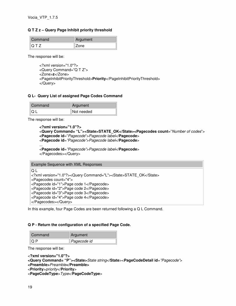
Q T Z z – Query Page Inhibit priority threshold
Command Argument
Q T Z Zone
The response will be:
<?xml version="1.0"?> <Query Command=”Q T Z”> <Zone>z</Zone> <PageInhibitPriorityThreshold>Priority</PageInhibitPriorityThreshold> </Query>
Q L- Query List of assigned Page Codes Command
Command Argument
Q L Not needed
The response will be:
<?xml version="1.0"?> <Query Command= “L”><State>STATE_OK</State><Pagecodes count=”Number of codes”> <Pagecode id=”Pagecode”>Pagecode label</Pagecode> <Pagecode id=”Pagecode”>Pagecode label</Pagecode> ... <Pagecode id=”Pagecode”>Pagecode label</Pagecode> </Pagecodes></Query>
Example Sequence with XML Responses
Q L <?xml version="1.0"?><Query Command="L"><State>STATE_OK</State> <Pagecodes count="4"> <Pagecode id="1">Page code 1</Pagecode> <Pagecode id="2">Page code 2</Pagecode> <Pagecode id="3">Page code 3</Pagecode> <Pagecode id="4">Page code 4</Pagecode> </Pagecodes></Query>
In this example, four Page Codes are been returned following a Q L Command.
Q P - Return the configuration of a specified Page Code.
Command Argument
Q P Pagecode id
The response will be:
<?xml version="1.0"?> <Query Command= “P”><State>State string</State><PageCodeDetail id=”Pagecode”> <Preamble>Preamble</Preamble> <Priority>priority</Priority> <PageCodeType>Type</PageCodeType>

System Control
20
<PageCodeLabel>label</PageCodeLabel> <AutoRepeat enabled=Repeatstate> <Count> <Min>1</Min> <Default>1</Default> <Max>9999</Max> </Count> <Interval> <Min>0</Min> <Default>0</Default> <Max>43200</Max> </Interval> </AutoRepeat> <Zones count=”Number of zones”> <Zone id=”Id”>”Zone name string”</Zone> <Zone id=”Id”>”Zone name string”</Zone> <Zone id=”Id”>”Zone name string”</Zone> </Zones></PageCodeDetail></Query>
Where:
"State string" will be one of:
• STATE_OK – if the command completed successfully.
• STATE_FAULT – if an error occurred.
"Pagecode" is a decimal number between 1 and 999
"Preamble" will be
• Y preamble will be used.
• N preamble will not be used.
"Type" can be one of the following:
• PAGE_TYPE_LIVE – audio from the paging microphone will go live to the destination zones.
• PAGE_TYPE_DELAYED – audio from the paging microphone will be stored before a delayed release.
• PAGE_TYPE_PLAYBACK – initiate a pre-recorded announcement. "RepeatState" can be
• true
• false
If the "RepeatState" is 'true' then the <Count> and <Interval> values will show the Page Code auto repeat configured values.
Example Sequence with XML Responses
Q P 1 <?xml version="1.0"?><Query Command="P"><State>STATE_OK</State><PageCodeDetail id="1"> <Preamble>N</Preamble> <Priority>1</Priority> <PageCodeType>PAGE_TYPE_LIVE</PageCodeType> <PageCodeLabel>Page Code 1</PageCodeLabel> <AutoRepeat enabled=false> <Count> <Min>1</Min> <Default>1</Default> <Max>9999</Max>

Vocia_VTP_1.7.5
21
</Count> <Interval> <Min>0</Min> <Default>0</Default> <Max>43200</Max> </Interval> </AutoRepeat> <Zones count="1"> <Zone id="1">Zone 1</Zone></Zones></PageCodeDetail></Query>
Q S - Return the current operating state of the paging station.
Command Argument
Q S Not needed
The response will be:
<?xml version="1.0"?><Query Command= “S”><State>State string</State>
<PagingStationState>State</PagingStationState></Query>
"State" will be one of the following:
• PXY_DEST_IDLE – The paging station is currently idle and the current destination is also idle.
• PXY_DEST_BUSY – The paging station is currently idle and the current destination is busy at a priority less than the current pagecode.
• PXY_DEST_DELAY – The paging station is currently idle and the current destination is busy at a priority greater than or equal to the current pagecode.
• PXY_NOT_AVAIL – The paging station is not available for use (most likely because it has no configuration).
• PXY_PLEASE_WAIT – The station is waiting for the audio path to be established and the preamble to finish.
• PXY_REQUEST_FAILED – The last recorded announcement request failed.
• PXY_PLEASE_TALK_NOW – The station is paging and is transmitting microphone audio to the destination zones.
• PXY_REQUEST_QUEUED – The recorded announcement request has been accepted and queued for playback.
• PXY_CANCEL_REQUEST – A delayed page has been recorded. The operator now has an opportunity to cancel it.
• PXY_PAGE_WILL_END – The current page is about to time out.
• PXY_SECURITY – The paging station has been locked for security reasons. A PIN is required to unlock it.
• PXY_NO_DEST – The station currently has no current valid destination.
• PXY_REQUEST_TIMEOUT – The current page has now timed out and has been terminated.
• PXY_NO_DEST_REQUESTED – The page failed because there were no destination devices to receive the page.
State string will be one of:
• STATE_OK – if the command completed successfully.
• STATE_FAULT – if an error occurred.
Example Sequence with XML Responses
Q S <?xml version="1.0"?><Query Command="S"><State>STATE_OK</State>

System Control
22
<PagingStationStatus>PXY_SECURITY</PagingStationStatus></Query> V 1234 <?xml version="1.0"?><Status Command="V"> <State>AUTH_SUCCESS</State></Status> Q S <?xml version="1.0"?><Query Command="S"><State>STATE_OK</State> <PagingStationStatus>PXY_DEST_IDLE</PagingStationStatus></Query>
Q Z - Return a list of all the available zones in the world.
Command Argument
Q Z Not needed
The response will be:
<?xml version="1.0"?><Query Command= “Z”><State>State string</State><Zones count=”Number of zones”><Zone id=”Id”>”Zone name string”</Zone><Zone id=”Id”>”Zone name string”</Zone>...<Zone id=”Id”>”Zone name string”</Zone><Zone id=”Id”>”Zone name string”</Zone></Zones></Query>
Where State string will be one of:
• STATE_OK – if the command completed successfully.
• STATE_FAULT – if an error occurred.
Note: The zone “Id” corresponds directly with the Zone numbers configured in the Vocia Configuration.
In the case of EWS emergency paging stations the list of zones will include only emergency zones.
Example Sequence with XML Responses
Q Z <?xml version="1.0"?><Query Command="Z"><State>STATE_OK</State> <Zones count="4"> <Zone id="1">Zone 1</Zone> <Zone id="2">Zone 2</Zone> <Zone id="3">Zone 3</Zone> <Zone id="4">Zone 4</Zone> </Zones></Query>
Pagecode Command (P)
The P command allows the third party application to select a Page Code from one of those in the list of configured codes (see Q L command). This Page Code will then be used for subsequent pages until another Page Code is selected or modified. The page code defines the type of page, its priority, the destination zones, whether or not a preamble will be played prior to the announcement and the default number of repeats and repeat time. The Page Code repeat parameters will always be available via VTP - these can be customized and defined separately using the R N, R I and R T commands. See the Auto_Repeat_options section for more details
Command Argument
P Pagecode id

Vocia_VTP_1.7.5
23
The response will be:
<?xml version="1.0"?><Status Command= “P”> <State>State string</State></Status>
State string will be one of:
• STATE_OK – if the command completed successfully.
• STATE_FAULT – if an error occurred or the requested Page Code does not exist.
• AUTH_FAIL – if the paging station was PIN locked.
Example Sequence with XML Responses
P 1 <?xml version="1.0"?><Status Command="P"><State>STATE_OK</State></Status> P 2 <?xml version="1.0"?><Status Command="P"><State>STATE_OK</State></Status>
Examples of Page Codes with Custom Repeat settings
PageCode Command with Auto Repeat User adjustable repetition count and Interval defined
Command and Sequence Argument
P Pagecode id
R N Quantity
R T Time
Example Sequence with XML Responses - Specifying 5 repeats every 100 seconds
P 1
<?xml version="1.0"?><Status Command="P"><State>STATE_OK</State></Status>
R N 5
<?xml version="1.0"?><Status Command="R"><State>STATE_OK</State></Status>
R T 100
<?xml version="1.0"?><Status Command="R"><State>STATE_OK</State></Status>
Zone Commands (Z)
Use the “Z” command to specify a set of custom destination paging zones for subsequent Live or Pre-recorded pages. This will override the current destination zone selection.
Z Z zones -Specify destination zones using a space delimited list of zone numbers.
Command Argument
Z Z zone/s id
The response will be:
<?xml version="1.0"?><ZonesStatus Command= “Z”><State>State string</State></ZonesStatus>

24
State string will be one of:
• STATE_OK – if the command completed successfully.
• STATE_FAULT – if an error occurred.
• AUTH_FAIL – if the paging station was PIN locked.
Example Sequence with XML Responses
Z Z 1 2 3 55 <?xml version="1.0"?><ZonesStatus Command="Z"><State>STATE_OK</State></ZonesStatus>
Sets zone allocation for zones 1,2,4 & 55.
Z A - Request that all available zones be used as a destination for the next page.
Command Argument
Z A Not needed
Note that for EWS emergency paging stations this command will select only emergency paging zones.
The response will be:
<?xml version="1.0"?><ZonesStatus Command= “A”><State>State string</State></ZonesStatus>
State string will be one of:
• STATE_OK – if the command completed successfully.
• STATE_FAULT – if an error occurred.
• AUTH_FAIL – if the paging station was PIN locked.
Example Sequence with XML Responses
Z A <?xml version="1.0"?><ZonesStatus Command="A"><State>STATE_OK</State></ZonesStatus>
Set Page Options command (O)
The O command is used to “lock in” the zones specified in a previous Z Z or Z A command, as well as specify the priority of the page, whether or not it will use a preamble, and whether it is a live or delayed page. The Page Code repeat parameters will always be available via VTP - these can be customized and defined separately using the R N, R I and R T commands. See the Auto_Repeat_options section for more details. The priority parameter will only accept a priority in the appropriate paging priority range for the paging station (ie. in the regular paging priority range for the DS-4, DS-10, WS-4 and WS10 and in the emergency paging priority range for the EWS-4 and EWS-10). The ‘O’ command will respond with a STATE_FAULT type response if the priority is outside the appropriate paging priority range for the paging station. The 'O' command replaces the depricated 'S' command (pre 1.6)
Command Argument
O pre pri delay
• preamble (pre) is Y if a preamble is required and N otherwise.

Vocia_VTP_1.7.5
25
• priority (pri) is required to be a number within the page priority threshold (regular paging range and emergency paging range depending on device role).
• delayed (delay) is N for a live page, or Y for a delayed page.
The response will be:
<?xml version="1.0"?><Status Command= “O”><State>State string</State></Status>
State string will be one of:
• STATE_OK – if the command completed successfully.
• STATE_FAULT – if an error occurred.
• AUTH_FAIL – if the paging station was PIN locked.
Example Sequence with XML Responses
Z Z 1 2 3
<?xml version="1.0"?><ZonesStatus Command="Z"><State>STATE_OK</State></ZonesStatus> O N 4 N <?xml version="1.0"?><Status Command="O"><State>STATE_OK</State></Status>
Examples of Page Codes with Custom Repeat settings
Set Page Options Command with Auto Repeat User adjustable repetition count and Interval defined.
Command and Sequence Argument
Z Z Zone number
O pre pri delay
R N Quantity
R T Time
Example Sequence with XML Responses - Specifying 5 repeats every 100 seconds
Z Z 1 2 3 <?xml version="1.0"?><ZonesStatus Command="Z"><State>STATE_OK</State></ZonesStatus> O N 4 N <?xml version="1.0"?><Status Command="O"><State>STATE_OK</State></Status> R N 5 <?xml version="1.0"?><Status Command="R"><State>STATE_OK</State></Status> R T 100 <?xml version="1.0"?><Status Command="R"><State>STATE_OK</State></Status>
Auto Repeat options (R)
Auto repeat options are configurable via PS-VTP per paging station and operate regardless of the selected Page Code pre-configured auto-repeat parameters. Repeat parameters must be defined via VTP

26
to suit the required operation. Consideration should be given to track the current active repeat mode of the paging station.
R C - used to cancel a repeating Page.
Command Argument
R C Not needed
Cancels any active repeating pages.
R N - specify the number of times a particular announcement will be repeated
Command Argument
R N Quantity (number)
Quantity can be specified between 1 and 9999.
The ability to specify the number of repeats via VTP will never be inhibited. The number of repeats will default to zero, so no repetition of announcements will occur. If a repeat count has been defined on an earlier VTP command this will persist for all subsequent pages and page codes. Set the repeat count back to zero ( R N 0 ) if repetition is no longer required.
R I - used to request infinite playback of announcements.
Command Argument
R I Not needed
Active Infinite page announcements can only be stopped using the 'R C' command.
The ability to specify infinite playback via VTP will never be inhibited. The infinite playback setting will persist for all subsequent pages and page codes. After being enabled the R I command can be disabled with the R N command.
R T - specify the time interval in seconds between repetitions for subsequent announcements
Command Argument
R T time (seconds)
The time will be specified in seconds and must be less than or equal to 43200 (12 hours).
The ability to specify the repeat interval via VTP will never be inhibited. The repeat interval will default to zero seconds. If the repeat interval has been defined on an earlier VTP command this will persist for all subsequent pages and page codes. Set the repeat interval back to zero ( R T 0 ) if repetition is no longer required.
Examples of Page Codes with Custom Repeat settings
PageCode Command with Auto Repeat User adjustable repetition count and Interval defined
Command and Sequence Argument

Vocia_VTP_1.7.5
27
P Pagecode id
R N Quantity
R T Time
Example Sequence with XML Responses - Specifying 5 repeats every 100 seconds
P 1 <?xml version="1.0"?><Status Command="P"><State>STATE_OK</State></Status> R N 5 <?xml version="1.0"?><Status Command="R"><State>STATE_OK</State></Status> R T 100 <?xml version="1.0"?><Status Command="R"><State>STATE_OK</State></Status>
Push to Talk command (T)
The T command is used to “press” or “depress” the push-to-talk button.
T state
Command Argument
T state
Where state is Y to depress the push-to-talk, or N to release it. If the Push To Talk has been enabled with a T Y it must be reset with a T N before sending any new Paging commands.
The response will be:
<?xml version="1.0"?><Status Command= “T”><State>State string</State></Status>
State string will be one of:
• STATE_OK – if the command completed successfully.
• STATE_FAULT – if an error occurred.
• AUTH_FAIL – if the paging station was PIN locked.
Example Sequence with XML Responses
T Y <?xml version="1.0"?><Status Command="T"><State>STATE_OK</State></Status> T Y <?xml version="1.0"?><Status Command="T"><State>STATE_OK</State></Status>
Delayed Page Send/Cancel command (D)
The “D” command is used to send or cancel a delayed page.
D action
Command Argument
D action
Where action is S to send the delayed page, or C to cancel the delayed page.

28
The response will be:
<?xml version="1.0"?><DelayedPageStatus Command= “S”><State>State string</State></DelayedPageStatus>
State string will be one of:
• STATE_OK – if the command completed successfully.
• STATE_FAULT – if an error occurred.
• AUTH_FAIL – if the paging station was PIN locked.
Set Page Options command (S)
Note
The ‘S’ command has been deprecated in Vocia release 1.6. Please refer to the O_- Set_Page_Options_command . The paging station firmware will include support for it in order to provide backwards compatibility with existing systems. It will continue to accept a paging priority in the range 1-4, provided the Emergency Paging Priority threshold is set to the legacy value = 5. This will mean that for emergency paging stations, the priority used for a page that is setup via PS VTP will be equal to the value of priority supplied via PS VTP plus the Emergency Paging Priority Threshold minus one. For example:
• Emergency Paging Priority Threshold = 5
• Value of priority supplied via PS VTP = 2 (i.e. Emergency Medium)
• Actual priority used for an emergency page = 2 + 5 - 1 = 6 The Vocia logger will also note a 'command has been deprecated' error whenever this command is used.
PS VTP XML Responses
PS VTP is an ASCII, line based protocol. This makes it simple to debug and experiment without using dedicated tools. Commands are entered as a single command letter, followed by a string of arguments relevant to the command, and a newline <LF> or carriage return <CR> to terminate and execute the command. Commands are case-insensitive, and commands and arguments are separated by whitespace (space, TAB, etc).
All PS VTP responses are in XML to facilitate parsing by third party applications. Each XML Response has been detailed after the appropriate command within the PS VTP Commands section of this help file. A response markup language conforming to XML is used for all responses from the Aux Port Interface. These responses take the following form.
Data elements are identified using tags:
<element>element data</element>
There can be sub elements within elements:
<element> <subelement>subelement data</subelement> </element>
Elements may also have an attribute field:
<element attribute=value>element data</element>
A typical response element will be as follows:
<?xml version="1.0"?><Reply Command=”Command character”>Reply data</Reply>
Vocia_VTP_1.7.5
29
The response echoes the Command character. The reply data may consist of a number of sub elements.
There will always be a State sub element.
<State>State string</State>
The state string will be one of the following:
• STATE_OK - indicating successful execution of the command.
• STATE_FAULT - indicating some form of error occurred.
• AUTH_SUCCESS - indicating that the Validate PIN (V) command successfully unlocked the paging station.
• AUTH_FAIL - indicating that the command failed due to the paging station being PIN locked.
LSI-16 VTP
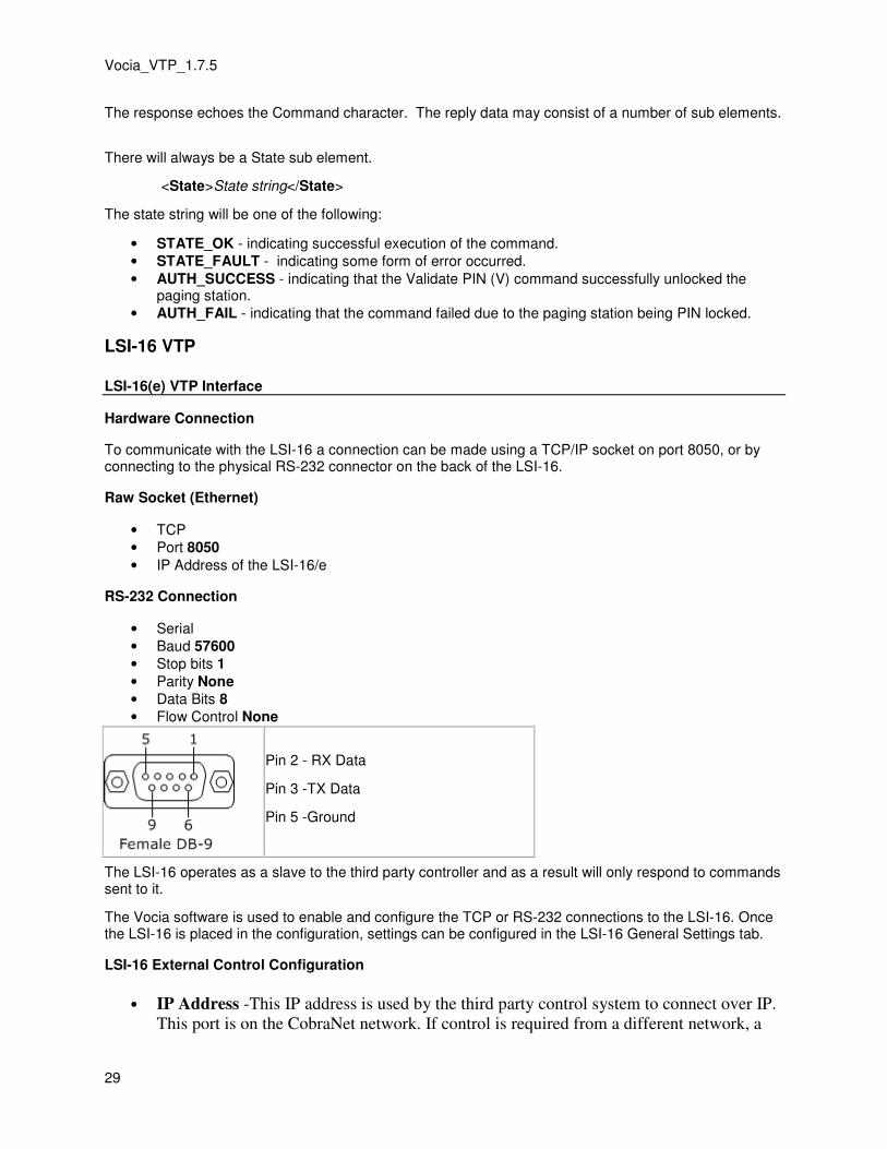
LSI-16(e) VTP Interface
Hardware Connection
To communicate with the LSI-16 a connection can be made using a TCP/IP socket on port 8050, or by connecting to the physical RS-232 connector on the back of the LSI-16.
Raw Socket (Ethernet)
• TCP
• Port 8050
• IP Address of the LSI-16/e
RS-232 Connection
• Serial
• Baud 57600
• Stop bits 1
• Parity None
• Data Bits 8
• Flow Control None
Pin 2 - RX Data
Pin 3 -TX Data
Pin 5 -Ground
The LSI-16 operates as a slave to the third party controller and as a result will only respond to commands sent to it.
The Vocia software is used to enable and configure the TCP or RS-232 connections to the LSI-16. Once the LSI-16 is placed in the configuration, settings can be configured in the LSI-16 General Settings tab.
LSI-16 External Control Configuration
• IP Address -This IP address is used by the third party control system to connect over IP.
This port is on the CobraNet network. If control is required from a different network, a

30
router port will need to be configured and the LSI-16 gateway would need to be specified
to facilitate this.
• Security-User name and password will be used to authenticate a TCP session. The User
Name and Password are case sensitive and must not contain any spaces. VTP Users are
limited to a 16 character user name and password. Authentication is not required for a
RS-232 session.
• Connection Type – the RS-232 and TCP connection method can be selected here.
• TCP Connections (appear if TCP is enabled as a connection type) Up to four
connections can be specified. These connections can be enabled or disabled as required.
The connection name is a customizable field that is used as the ‘connection id’ when
using the H (Handshake) command. Each connection name has to be unique and if the
connection is enabled, the connection must have a name.
Fig 2 – Screenshot of LSI-16 General Settings Tab
LSI-16 VTP Glossary
User Authorization
• U – specify user.
• P – specify password.
• A – authenticate the user’s password.
Handshake Command
• H – enable TCP handshaking using a token. Using RS-232 requires the use of the H handshake command.
Set and Get Commands
• I – set the state of a virtual Input.
• G - set the state of multiple virtual Inputs.
• R S - Reset System Fault
• Z Z– Return the status of a specified emergency zone.
• Z A– Return the status of all emergency zones.
Configuration Query Commands
• Q D – Return a list of all emergency mode devices in a world.
• Q I - Query the type of Virtual Input in the World.
• Q L - Query a list of all Virtual Inputs assigned on a LSI-16.
• Q Z – Return a list of all emergency zones in a world.
Fault Status Commands
• F S – Fault status summary of the LSI-16.
• F D – Fault listing for the specified device being monitored by the LSI-16.
• F F – Returns a summary of all active faults.
• F A – Acknowledge faults. Will de-activate the fault sounder.

Vocia_VTP_1.7.5
31
Emergency Paging Station control via LSI-16(e)
• @- Relay a specific VTP command to an Emergency Paging Station in the local World
LSI-16 VTP Commands
LSI-16 VTP Commands
Login Commands
The U, P and A commands will be the only commands available until the remote LSI-16 VTP user has been authorized.
U – Username
Command Argument
U Username
The U command will be used to supply a Username in order to gain access to the LSI-16 TCP/IP interface. This command must be executed prior to sending the P command. The U, P and A commands will be only ones available until the remote LSI VTP user has been authorized.
If connecting Via RS-232 no authentication is required
P – Password
Command Argument
P Password
The P command will be used to supply a password in order to gain access to the LSI-16 RS-232 or TCP/IP interface. This command must be executed prior to sending the A command. The U, P and A commands will be only ones available until the remote LSI VTP user has been authorized.
If connecting Via RS-232 no authentication is required
A – Authorization
Command Argument
A Not needed
The A command will be used to authorize a LSI-16 VTP User with the LSI-16 and gain access to the protected VTP control via the LSI-16 VTP interface. It is necessary to first send a Username and password using the U and P commands respectively. The U, P and A commands will be only ones available until the remote LSI-16 VTP user has been authorized. Responses will be of the form specified in XML Responses.
If connecting Via RS-232 no authentication is required
Example Sequence with XML Responses

32
### Welcome to the Vocia LSI U admin <?xml version="1.0"?><Status Command="U"><State>STATE_OK</State></Status> P admin <?xml version="1.0"?><Status Command="P"><State>STATE_OK</State></Status> A <?xml version="1.0"?><Status Command="A"><State>AUTH_SUCCESS</State></Status>
Handshake Commands (H)
H – Handshake
Connection Command Argument State
TCP H connection id ( 1, 2, 3, 4 )
token then next token
RS-232 H connection id (0)
token then next token
The H command is used by the LSI-16 to ascertain the integrity of a RS-232 or TCP/IP connection. A token is passed between the LSI-16 VTP user and the LSI-16. This token is an unsigned integer that the LSI-16 compares with a stored copy of the last token transmitted. If these match then the connection will be reported as good. If a matching token is not received by the LSI-16 within 15 seconds of the last good token received the connection will be declared bad and a path fault generated. A valid handshake command should be sent to the LSI-16 every five seconds.
For TCP and RS-232 Connections the remote LSI-16 VTP user will be required to supply a connection ID. For TCP connections this is a numerical value (1-4) and should correspond with one of the four enabled monitored TCP Connections configured in the LSI-16 General Settings tab. For RS-232 connections this is always the number 0. Using RS-232 requires the use of the H handshake command.
If handshake communications are lost, a Path Fault will be indicated on the front panel of the LSI-16, and the LSI-16 Alarms and Log tab will show a bad transmission path alarm. If connected via TCP/IP an LSI-16 TCP/IP transmission path will indicate as BAD. If connected via RS-232 a LSI-16 RS-232 transmission path will indicate as BAD.
• The TCP connectionid is a numerical value of 1 to 4.
• The RS-232 connectionid is always a value of 0.
• The Token will always start at 0 (zero).
• The LSI-16 responds with the next token to be used for the next handshake. This needs to be sent as the new token.
Example Sequence with XML Responses
H 1 0 <?xml version="1.0"?><Status Command="H"><State>STATE_OK</State><Token>1<Token></Status> H 1 1 <?xml version="1.0"?><Status Command="H"><State>STATE_OK</State><Token>2<Token></Status> H 1 2

Vocia_VTP_1.7.5
33
<?xml version="1.0"?><Status Command="H"><State>STATE_OK</State><Token>3<Token></Status>
Input Command (I)
I - Input State
Command Argument Argument
I Input number state
The I command will be used by the LSI-16 VTP User to set the state of a virtual input. Virtual inputs behave much like the inputs of an IM-16. They can be configured in the Vocia GUI in the LSI-16 Virtual Inputs tab to perform one of the following functions:
• Disabled
• Alarm
• Fault
• Reset
• Reset All
• Silence All
Fault inputs are level sensitive. If the input is ON then the fault is active. If the input is OFF the fault is inactive. All other virtual input types are positive edge triggered – they will enable on a low to high transition. So a command to set the input to ON will enable the associated function (the zone virtual input will go active), whereas a command to turn the input OFF will be ignored.
To enable Virtual Input 1 the command will be: I 1 1
To disable Virtual Input 1 the command will be: I 1 0
The Virtual Input Channel Number is the channel number as listed in the Vocia GUI under LSI-16 properties/ Virtual Inputs.
State sets the specified input ON (state = 1) or OFF (state = 0). The response will be:
<?xml version="1.0"?><Status Command= “I”> <State> STATE_OK</State></Status>
Example Sequence with XML Responses
I 1 0 <?xml version="1.0"?><Status Command="I"><State>STATE_OK</State></Status> I 1 0 <?xml version="1.0"?><Status Command="I"><State>STATE_OK</State></Status>
Group Input Command (G)
G - Group Input State
Command Argument Delimiter Argument Argument
G Lowest Input number
- Highest Input number
state

34
The G command can be used to set the state of multiple virtual inputs at once (maximum 50 inputs per 'G' command). Virtual inputs behave much like the inputs of an IM-16. They can be configured in the Vocia GUI in the LSI-16 Virtual Inputs tab to perform one of the following functions:
• Disabled
• Alarm
• Fault
• Reset
• Reset All
• Silence All
Fault inputs are level sensitive. If the input is ON then the fault is active. If the input is OFF the fault is inactive. All other virtual input types are positive edge triggered – they will enable on a low to high transition. So a command to set the input to ON will enable the associated function (the Zone virtual input will go active), whereas a command to turn the input OFF will be ignored.
To enable Virtual Inputs 20 through 30, the command will be: G 20-30 1
To disable Virtual Inputs 5 to 10, command will be: G 5-10 0
Note that the delimiter character ("-") is always required to seperate a range of indexes.
The Virtual Input Channel Number is the channel number as listed in the Vocia GUI under LSI-16 properties/ Virtual Inputs.
State sets the specified input ON (state = 1) or OFF (state = 0). The response will be:
<?xml version="1.0"?><Status Command= “G”> <State> STATE_OK</State></Status>
Example Sequence with XML Responses
G 10-30 0 <?xml version="1.0"?><Status Command="G"><State>STATE_OK</State></Status> G 50-55 1 <?xml version="1.0"?><Status Command="G"><State>STATE_OK</State></Status>
Reset System Fault (R S)
R S - Reset System Fault command
The R S command will allow the System Fault alarm to be reset if the LSI-16(e) has been configured to support remote resetting of system fault via VTP.
In a Master-Slave Emergency system, if this command is issued to the Master LSI-16(e) and the “Reset on Master Triggers Reset on All Slaves” option is enabled then all Slave LSI-16(e)’s will also have their System Fault reset.
Command Argument
R S Not needed
The F S command can be used to obtain the current fault status from the LSI-16(e).
The XML Response if successful will be

Vocia_VTP_1.7.5
35
<?xml version=\"1.0\"?> <Reset Command="R S"> <State>STATE_OK</State> </Reset>
The XML Response if there is an error will be
<?xml version=\"1.0\"?> <Reset Command="R S"> <State>STATE_FAULT</State> </Reset>
Emergency Zone Status Commands (Z)
Z – Zone status command
Command Argument
Z Z zone id
The Z Z command will be used to obtain the current status of a particular emergency zone. The Q Z Command can be used to get a listing of current configured Emergency Zones.
The status of a zone can be Inactive, Muted, or Announcing. If the zone is in the Announcing state, the response will contain the name of the announcement currently playing in that zone.
The Zone Id will be the emergency zone id number assigned in the Vocia configuration. One Emergency Zone can be specified at a time.
• The ZoneState tag will return the default state of the zone as defined by the LSI-16. This state does not incorporate emergency paging in any form. It will report as Inactive, Muted, Announcing
• Inactive : Normal mode paging, background music and emergency pages will be heard in the zone.
• Muted : All normal mode paging, background music and emergency recorded announcements are muted. Only emergency pages will be allowed.
• Announcing: The emergency zone will continually play an emergency announcement in a looping fashion. All normal mode paging, background music will be muted. Emergency pages take priority.
The ZoneAvailable tag indicates if there are available operational output channels for the Emergency Zone. Supported Output devices include the VA-8600, VA-2060, VA-4030 and VO-4e.
Will be either
• Yes - At least one output channel with the specified Emergency Zone is available.
• No - There are no operational emergency output channels available.
The <ZoneMessage> tag is only present if the zone state is Announcing.
XML response <?xml version="1.0"?><ZoneStatus Command= “Z”><State> STATE_OK</State><Zone Id=zone><ZoneState>Zone state</ ZoneState><ZoneAvailable>Yes/No</ZoneAvailable><ZoneMessage>”Message Name”</ ZoneMessage></ZoneStatus>

36
Z A- Specify Zone status of all emergency zones
Command Argument
Z A not needed
The Z A command will be used to obtain the current status of a all emergency zones in a World. The status of a zone can be Inactive, Muted, or Announcing. If the zone is in the Announcing state, the response will contain the name of the announcement currently playing in that zone.
The Zone Id will be the emergency zone id number assigned in the Vocia configuration.
• The ZoneState tag will return the default state of the zone as defined by the LSI-16. This state does not incorporate emergency paging in any form. It will report as Inactive, Muted, Announcing
• Inactive : Normal mode paging, background music and emergency pages will be heard in the zone.
• Muted : All normal mode paging, background music and emergency recorded announcements are muted. Only emergency pages will be allowed.
• Announcing: The emergency zone will continually play an emergency announcement in a looping fashion. All normal mode paging, background music will be muted. Emergency pages take priority.
The ZoneAvailable tag indicates if there are available operational output channels for the Emergency Zone. Supported Output devices include the VA-8600, VA-2060, VA-4030 and VO-4e.
Will be either
• Yes - At least one output channel with the specified Emergency Zone is available.
• No - There are no operational emergency output channels available.
The <ZoneMessage> tag is only present if the zone state is Announcing.
The XML Response will be
<?xml version="1.0"?><ZoneStatus Command= “A”><State> STATE_OK</State><Zones count=number of zones> <Zone Id=zone1><ZoneState>Zone1 state</ ZoneState > <ZoneAvailable>Yes/No</ ZoneAvailable > <ZoneMessage>”Message Name”</ ZoneMessage></Zone> <Zone Id=zone2><ZoneState>Zone2 state</ ZoneState > <ZoneAvailable>Yes/No</ ZoneAvailable > <ZoneMessage>”Message Name”</ ZoneMessage></Zone> <Zone Id=zoneM><ZoneState>ZoneM state</ ZoneState > <ZoneAvailable>Yes/No</ ZoneAvailable > <ZoneMessage>”Message Name”</ ZoneMessage></Zone> <Zone Id=zoneN><ZoneState>ZoneN state</ ZoneState > <ZoneAvailable>Yes/No</ ZoneAvailable > <ZoneMessage>”Message Name”</ ZoneMessage></Zone></Zones</ZoneStatus>
Query configuration command (Q)
The Q command is used to query aspects of the LSI-16’s configuration. Commands are provided to display a list of all emergency mode devices and a list of all emergency zones.
Q D Return a list of all the emergency devices in the world.
Command Argument

Vocia_VTP_1.7.5
37
Q D not needed
The response will be:
<?xml version="1.0"?><Query Command= “D”><State> STATE_OK</State> <Devices count=”Number of devices”> <Device type="Type" id=”Id”>”TypeString”:”Id”</Device> <Device type="Type" id=”Id”>” TypeString”:”Id”</Device> ... <Device type="Type" id=”Id”>” TypeString”:”Id”</Device> <Device type="Type" id=”Id”>” TypeString”:”Id”</Device> </Devices></Query>
"Type" and "Typstring" Values
Valid "Type" and "TypeString" are as follows:
Note:
• The response relates to emergency equipment only. EWS-4 and EWS-10 paging stations are reported as WS-4 and WS10 respectively.
• The VI-8, VOIP-1 and POTS-1 will only be included if configured for emergency paging functions
• The Valid ID range is a hex value based on the MSB and LSB Device ID. For a device that has a MSB of 0 and LSB of 5, the value returned will be 0x05.
Device Type Device Name Valid ID Range
2 WS-4 01 - FF
4 WS-10 01 - FF
8 LSI-16 01 - FF
10 VO-4e 01 - FF
12 VA-8600 01 - FF
14 GPIO-1 01 - FF
17 VA-4030(e) 01 - FF
18 VA-2060(e) 01 - FF
32 VI-8 01 - FF
33 VOIP-1 01 - FF
34 POTS-1 01 - FF
Q I – Query the type of Virtual Input.
Command Argument
Q I InputID

38
InputID is a numerical value of the Virtual Input. This can be obtained using the ‘Q L’ Command. A response with the details of a specific virtual input configuration will be provided. The response format will depend on how the virtual Input is configured.
Possible Virtual Input Configurations with XML Responses
Virtual Input configured as a Fault Input:
The response will be:
<?xml version="1.0"?> <Query Command= “I”><State> STATE_OK</State> < VirtualInputDetail id=”Input Id”><Name>”Input name string”</ Name > <Description>”Input description string”</ Description> <Function>”Fault”</Function> <FaultType>”Input Fault Type”</ FaultType > </VirtualInputDetail ></Query>
The input fault type can be one of the following:
• PSU
• Ethernet
• Protection
• Transmission Path
Virtual Input configured as a Alarm Input:
The response will be:
<?xml version="1.0"?><Query Command= “I”><State> STATE_OK</State> < VirtualInputDetail id=”Input Id”><Name>”Input name string”</ Name > <Description>”Input description string”</ Description> <Function>”Alarm”</Function> <Zone id=”Id”>”Zone name string”</Zone> <ZoneMessage>”Zone message string”</ ZoneMessage > </VirtualInputDetail ></Query>
The zone message string will be the Virtual Input label as configured in the Vocia software or:
• Mute - indicating that this input will mute the associated zone.
• Unknown - indicating a configuration parsing error.
Virtual Input configured as a Zone Reset Input:
The response will be: <?xml version="1.0"?><Query Command= “I”><State> STATE_OK</State> < VirtualInputDetail id=”Input Id”><Name>”Input name string”</ Name > <Description>”Input description string”</ Description> <Function>”Reset”</Function> <Zone id=”Id”>”Zone name string”</Zone> </VirtualInputDetail ></Query>
Virtual Input configured as an All Zone Silence Input:
The response will be: <?xml version="1.0"?> <Query Command= “I”><State> STATE_OK</State> < VirtualInputDetail id=”Input Id”><Name>”Input name string”</ Name > <Description>”Input description string”</ Description> <Function>”All silence”</Function> </VirtualInputDetail ></Query>
Virtual Input configured as a All Zone Reset Input:

Vocia_VTP_1.7.5
39
The response will be: <?xml version="1.0"?><Query Command= “I”><State> STATE_OK</State> < VirtualInputDetail id=”Input Id”><Name>”Input name string”</ Name > <Description>”Input description string”</ Description> <Function>”All reset”</Function> </VirtualInputDetail ></Query>
LSI-16 Virtual Inputs configured as follows
Example Sequence with XML Responses
### Welcome to the Vocia LSI U admin <?xml version="1.0"?><Status Command="U"><State>STATE_OK</State></Status> P admin <?xml version="1.0"?><Status Command="P"><State>STATE_OK</State></Status> A <?xml version="1.0"?><Status Command="A"><State>AUTH_SUCCESS</State></Status> Q I 1 <?xml version="1.0"?><Query Command="I"><State>STATE_OK</State><VirtualInputDetail id="1"> <Name>Virtual Input Channel 1</Name><Description>Virtual Input Channel</Description> <Function>Fault</Function><FaultType>PSU</FaultType></VirtualInputDetail></Query> Q I 2 <?xml version="1.0"?><Query Command="I"><State>STATE_OK</State><VirtualInputDetail id="2"> <Name>Virtual Input Channel 2</Name><Description>Virtual Input Channel</Description> <Function>Fault</Function><FaultType>Ethernet</FaultType></VirtualInputDetail></Query> Q I 3 <?xml version="1.0"?><Query Command="I"><State>STATE_OK</State><VirtualInputDetail id="3"> <Name>Virtual Input Channel 3</Name><Description>Virtual Input Channel</Description> <Function>Fault</Function><FaultType>Protection</FaultType></VirtualInputDetail></Query> Q I 4

40
<?xml version="1.0"?><Query Command="I"><State>STATE_OK</State><VirtualInputDetail id="4"> <Name>Virtual Input Channel 4</Name><Description>Virtual Input Channel</Description> <Function>Fault</Function><FaultType>TransmissionPath</FaultType></VirtualInputDetail></Query> Q I 5 <?xml version="1.0"?><Query Command="I"><State>STATE_OK</State><VirtualInputDetail id="5"> <Name>Virtual Input Channel 5</Name><Description>Virtual Input Channel</Description> <Function>Alarm</Function><Zone id="1">Emergency Zone 1</Zone> <ZoneMessage>Mute</ZoneMessage></VirtualInputDetail></Query> Q I 6 <?xml version="1.0"?><Query Command="I"><State>STATE_OK</State><VirtualInputDetail id="6"> <Name>Virtual Input Channel 6</Name><Description>Virtual Input Channel</Description> <Function>Reset</Function><Zone id="1">Emergency Zone 1</Zone></VirtualInputDetail></Query> Q I 7 <?xml version="1.0"?><Query Command="I"><State>STATE_OK</State><VirtualInputDetail id="7"> <Name>Virtual Input Channel 7</Name><Description>Virtual Input Channel</Description> <Function>All reset</Function></VirtualInputDetail></Query> Q I 8 <?xml version="1.0"?><Query Command="I"><State>STATE_OK</State><VirtualInputDetail id="8"> <Name>Virtual Input Channel 8</Name><Description>Virtual Input Channel</Description> <Function>All silence</Function></VirtualInputDetail></Query>
Q L - Return a list of all the virtual inputs configured for this LSI-16.
Command Argument
Q L not needed
The response will be:
<?xml version="1.0"?> <Query Command= “L”><State> STATE_OK</State> <VirtualInputs count=”Number of inputs”> <VirtualInput id=”Id”>”Input name string”</VirtualInput> <VirtualInput id=”Id”>”Input name string”</VirtualInput> ... <VirtualInput id=”Id”>”Input name string”</VirtualInput> </ VirtualInputs></Query>
The input “Id” is a 1 based input number.
Q Z Return a list of all the emergency zones in the World.
Command Argument
Q Z not needed
The response will be:
<?xml version="1.0"?><Query Command= “Z”><State> STATE_OK</State> <Zones count=”Number of zones”> <Zones id=”Id”>”Zone name string”</Zone>

Vocia_VTP_1.7.5
41
<Zones id=”Id”>”Zone name string”</Zone> ... <Zones id=”Id”>”Zone name string”</Zone> <Zones id=”Id”>”Zone name string”</Zone> </Zones></Query>
The zone “Id” is the zone number.
Example Sequence with XML Responses
QZ
<?xml version="1.0"?><Query Command="Z"><State>STATE_OK</State><Zones count="3">
<Zone id="1">Emergency Zone 1</Zone> <Zone id="2">Emergency Zone 2</Zone> <Zone id="3">Emergency Zone 3</Zone>
</Zones></Query>
Fault status command (F)
The F command will be used to obtain the current fault status from the LSI-16. Commands are provided to display a summary list of emergency faults, device specific faults all current faults.
F S - Requests the emergency fault summary status from the LSI-16.
Command Argument
F S not needed
Example Sequence with XML Responses
F S <?xml version="1.0"?><Faults Command="S"><State>STATE_OK</State><EmergencyFaults > <Fault type="Voice Alarm Active">STATE_OK</Fault> <Fault type="System Fault">STATE_FAULT</Fault> <Fault type="General Fault">STATE_FAULT</Fault> <Fault type="VACIE Power Fault">STATE_FAULT</Fault> <Fault type="Protection Fault">STATE_OK</Fault> <Fault type="Transmission Path Fault">STATE_OK</Fault> <Fault type="System Available">STATE_OK</Fault> <Fault type="System Configuration">STATE_OK</Fault> <Fault type="Multiple LSI-16 Masters">STATE_OK</Fault> <Fault type="Audio Path Fault">STATE_OK</Fault> <Fault type="Fault Sounder Active">STATE_FAULT</Fault> <Fault type="Software Fault">STATE_OK</Fault> <Fault type="Device Memory Failure">STATE_OK</Fault> <Fault type="Device Offline">STATE_OK</Fault> <Fault type="Unknown Device Detected">STATE_OK</Fault> <Fault type="Excessive Device Restarts">STATE_OK</Fault> <Fault type="Emergency Detection System Fault">STATE_FAULT</Fault> <Fault type="LSI-16 Master Restart">STATE_FAULT</Fault> <Fault type="Network Fault">STATE_OK</Fault> </EmergencyFaults></Faults>

42
F D - Return a fault listing for the specified device.
Command Argument Argument
F D DevType Devid
The F D command will return a fault listing for all Emergency Devices excluding the LSI-16(e)
The nature of the response will depend on the specified device and will include all information provided by the device to the LSI-16.
The response will be: <?xml version="1.0"?> <Faults Command= “D”><State> STATE_OK</State> <DeviceFaults type=" Type" Id= "Id"> <Fault type="System Fault">STATE_FAULT</Fault> <Fault type="General Fault">STATE_FAULT</Fault> <Fault type="Protection Fault">STATE_OK</Fault> <Fault type="System Configuration">STATE_OK</Fault> <Fault type="Audio Path Fault">STATE_FAULT</Fault> <Fault type="Device Memory Failure">STATE_OK</Fault> <Fault type="Device Offline">STATE_OK</Fault> </DeviceFaults></Faults>
Valid type and id strings are as follows:
Note:
• The response relates to emergency equipment only. EWS-4 and EWS-10 paging stations are reported as WS-4 and WS10 respectively.
• The VI-8, VOIP-1 and POTS-1 will only be included if configured for emergency paging functions
• The Valid ID range is a hex value based on the MSB and LSB Device ID. For a device that has a MSB of 0 and LSB of 5, the value returned will be 0x05.
Device Type Device Name Valid ID Range
2 WS-4 01 - FF
4 WS-10 01 - FF
8 LSI-16 01 - FF
10 VO-4e 01 - FF
12 VA-8600 01 - FF
14 GPIO-1 01 - FF
17 VA-4030(e) 01 - FF
18 VA-2060(e) 01 - FF
32 VI-8 01 - FF
33 VOIP-1 01 - FF
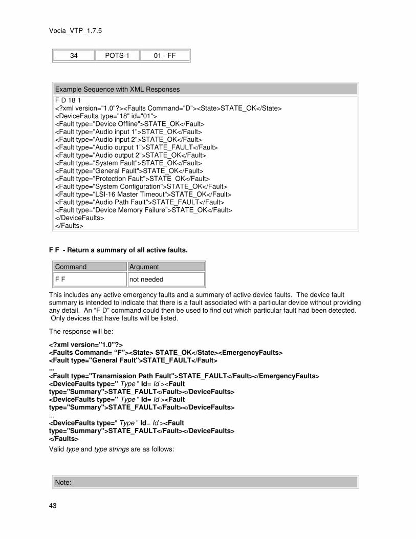
Vocia_VTP_1.7.5
43
34 POTS-1 01 - FF
Example Sequence with XML Responses
F D 18 1 <?xml version="1.0"?><Faults Command="D"><State>STATE_OK</State> <DeviceFaults type="18" id="01"> <Fault type="Device Offline">STATE_OK</Fault> <Fault type="Audio input 1">STATE_OK</Fault> <Fault type="Audio input 2">STATE_OK</Fault> <Fault type="Audio output 1">STATE_FAULT</Fault> <Fault type="Audio output 2">STATE_OK</Fault> <Fault type="System Fault">STATE_OK</Fault> <Fault type="General Fault">STATE_OK</Fault> <Fault type="Protection Fault">STATE_OK</Fault> <Fault type="System Configuration">STATE_OK</Fault> <Fault type="LSI-16 Master Timeout">STATE_OK</Fault> <Fault type="Audio Path Fault">STATE_FAULT</Fault> <Fault type="Device Memory Failure">STATE_OK</Fault> </DeviceFaults> </Faults>
F F - Return a summary of all active faults.
Command Argument
F F not needed
This includes any active emergency faults and a summary of active device faults. The device fault summary is intended to indicate that there is a fault associated with a particular device without providing any detail. An “F D” command could then be used to find out which particular fault had been detected. Only devices that have faults will be listed.
The response will be:
<?xml version="1.0"?> <Faults Command= “F”><State> STATE_OK</State><EmergencyFaults> <Fault type="General Fault">STATE_FAULT</Fault> ... <Fault type="Transmission Path Fault">STATE_FAULT</Fault></EmergencyFaults> <DeviceFaults type=" Type " Id= Id ><Fault type="Summary">STATE_FAULT</Fault></DeviceFaults> <DeviceFaults type=" Type " Id= Id ><Fault type="Summary">STATE_FAULT</Fault></DeviceFaults> ... <DeviceFaults type=" Type " Id= Id ><Fault type="Summary">STATE_FAULT</Fault></DeviceFaults> </Faults>
Valid type and type strings are as follows:
Note:

44
• The response relates to emergency equipment only. EWS-4 and EWS-10 paging stations are reported as WS-4 and WS10 respectively.
• The VI-8, VOIP-1 and POTS-1 will only be included if configured for emergency paging functions
• The Valid ID range is a hex value based on the MSB and LSB Device ID. For a device that has a MSB of 0 and LSB of 5, the value returned will be 0x05.
Device Type Device Name Valid ID Range
2 WS-4 01 - FF
4 WS-10 01 - FF
8 LSI-16 01 - FF
10 VO-4e 01 - FF
12 VA-8600 01 - FF
14 GPIO-1 01 - FF
17 VA-4030(e) 01 - FF
18 VA-2060(e) 01 - FF
32 VI-8 01 - FF
33 VOIP-1 01 - FF
34 POTS-1 01 - FF
Example Sequence with XML Responses
F F <?xml version="1.0"?><Faults Command="F"><State>STATE_OK</State><EmergencyFaults> <Fault type="General Fault">STATE_FAULT</Fault> <Fault type="Transmission Path Fault">STATE_FAULT</Fault> <Fault type="System Available">STATE_FAULT</Fault> <Fault type="Audio Path Fault">STATE_FAULT</Fault> <Fault type="Fault Sounder Active">STATE_FAULT</Fault> </EmergencyFaults> <DeviceFaults type="18" id="01"><Fault type="Summary">STATE_FAULT</Fault> </DeviceFaults> </Faults>
F A – Fault Acknowledge
Command Argument
F A not needed
This command operates as a virtual 'local Silence'. So performs the same way as physically pressing the 'Local Silence' on a CI-1 front panel.
The response will be:
<?xml version="1.0"?>

Vocia_VTP_1.7.5
45
<Faults Command=“A”> <State>STATE_OK</State></Faults>
Emergency Paging Station control via LSI-16(e) The "@" command is used to relay a specific VTP command to an emergency paging station or LSI-16(e) in the local World, via the LSI-16(e) hosting the current connection.
Command Argument
@ Dev_Type Dev_ID Command
• Device Type (Dev_Type) is '2' for an EWS-4, '4' for an EWS-10 and '8' for an LSI-16(e).
• Device ID (Dev_ID) is the unique identifier the device has been assigned formatted as a hex number. Valid ID range is 01 - FF.
• Command is a PS VTP string as specified. See the PS VTP Glossary for available commands. The response will be: <?xml version="1.0"?> <VTPRelay Command="@"> <Device type=”2” id=”05”>EWS-4:05</Device> <State>STATE_OK</State> <Response>[Response From EWS-4/EWS-10]</Response> </VTPRelay> Where [Response From EWS-4/EWS-10] is the PS-VTP response from the remote device. A <State>STATE_FAULT</State> response will be returned if the device specified is unable to be communicated with.
Example Sequence with XML Responses
@ 2 66 Q L <?xml version="1.0"?> <VTPRelay Command="@"> <Device type="2" id="66">EWS-4:66</Device> <State>STATE_OK</State> <Response> <Query Command="L"><State>STATE_OK</State><Pagecodes count="2"> <Pagecode id="1">Emergency Code 1</Pagecode> <Pagecode id="2">Emergency Code 2</Pagecode> </Pagecodes></Query> </Response> </VTPRelay>
Note: It is not possible to use the relay command to send a command to another LSI-16(e) that asks it to relay the command to a third device.


47
Glossary
T TTS-1 Sequence: This is made up of the zone information, priority level, voice and paging audio that you
require the TTS-1 to serve out to the Vocia devices. At least one sequence must be used if there is a TTS-1 being used.


49
Index
AAAA
Audio Path Fault 31
Auxiliary Port 15
HHHH
Handshake Command 31
Hardware Connection 29
IIII
Input Command 31
Input Fault Type 31
Input Id 31
Input State 31
Internal Function 6
LLLL
LSI VTP 31
LSI-16 VTP Commands 31
LSI-16 VTP Glossary 30
LSI-16 VTP Interface 29
PPPP
Paging Station Option Port 15
Path Fault 31
Port address 1
Possible Virtual Input Configurations 31
PS 16
PS VTP 28
PS VTP Interface 15
PS VTP responses 28
PS VTP XML Responses 28
PuTTY 3
RRRR
Request 31
SSSS
Security 29
Show Page Progress 7
TTTT
Text Protocol 1
Token 31
Transmission Path 31
TTS-1 VTP Commands 7
TTS-1 VTP Glossary 6
TTS-1 VTP Interface 5
VVVV
Vocia Text Protocol 1
VTP 1