VMX VIDEO WALL PROCESSING MATRIX USER MANUAL …€¦ · VMX VIDEO WALL PROCESSING MATRIX USER...
23
Transcript of VMX VIDEO WALL PROCESSING MATRIX USER MANUAL …€¦ · VMX VIDEO WALL PROCESSING MATRIX USER...
VMX VIDEO WALL PROCESSING MATRIX USER MANUAL V1.0
© 2016 Smart-e (UK) Ltd www.smart-e.co.uk PAGE | 2
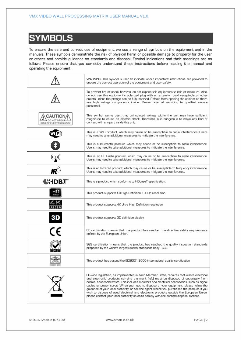
SYMBOLS To ensure the safe and correct use of equipment, we use a range of symbols on the equipment and in the
manuals. These symbols demonstrate the risk of physical harm or possible damage to property for the user
or others and provide guidance on standards and disposal. Symbol indications and their meanings are as
follows. Please ensure that you correctly understand these instructions before reading the manual and
operating the equipment.
WARNING. This symbol is used to indicate where important instructions are provided to ensure the correct operation of the equipment and user safety.
To prevent fire or shock hazards, do not expose this equipment to rain or moisture. Also, do not use this equipment’s polarized plug with an extension cord receptacle or other outlets unless the prongs can be fully inserted. Refrain from opening the cabinet as there are high voltage components inside. Please refer all servicing to qualified service personnel.
This symbol warns user that uninsulated voltage within the unit may have sufficient magnitude to cause an electric shock. Therefore, it is dangerous to make any kind of contact with any part inside this unit.
This is a WiFi product, which may cause or be susceptible to radio interference. Users may need to take additional measures to mitigate the interference.
This is a Bluetooth product, which may cause or be susceptible to radio interference. Users may need to take additional measures to mitigate the interference.
This is an RF Radio product, which may cause or be susceptible to radio interference. Users may need to take additional measures to mitigate the interference.
This is an Infrared product, which may cause or be susceptible to frequency interference. Users may need to take additional measures to mitigate the interference.
This is a product which conforms to HDbaseT specification.
This product supports full High Definition 1080p resolution.
This product supports 4K Ultra High Definition resolution.
This product supports 3D definition display.
CE certification means that the product has reached the directive safety requirements defined by the European Union.
SGS certification means that the product has reached the quality inspection standards proposed by the world's largest quality standards body - SGS.
This product has passed the ISO9001:2000 international quality certification
EU-wide legislation, as implemented in each Member State, requires that waste electrical and electronic products carrying the mark (left) must be disposed of separately from normal household waste. This includes monitors and electrical accessories, such as signal cables or power cords. When you need to dispose of your equipment, please follow the guidance of your local authority, or ask the agent where you purchased the product. If you wish to dispose of used electrical and electronic products outside the European Union, please contact your local authority so as to comply with the correct disposal method.
VMX VIDEO WALL PROCESSING MATRIX USER MANUAL V1.0
© 2016 Smart-e (UK) Ltd www.smart-e.co.uk PAGE | 3
WARNING
In order to ensure the reliable performance of the equipment and the safety of the user, please observe the following
matters during the process of installation, use and maintenance. :
INSTALLATION
Please do not use this product in the following places: places with high levels of dust or soot; places with high electric
conductivity; places with corrosive or combustible gas; places exposed to high temperature, condensation, wind or
rain; places subject to the occasion of vibration or impact.
When installing screw or wiring, make sure that metal scraps and wire heads will not fall into the screw shaft of the
equipment, as it could cause a fire, fault, or incorrect operation.
When the installation work is completed, ensure there is nothing left on the ventilated vents of the equipment,
including packaging items. Blocked vents may cause a fire, fault, incorrect operation.
Avoid wiring and inserting cable plugs in a charged state, otherwise it is easy to cause shock, or electrical damage.
The installation wiring should be strong reliable and earthed.
For installations in areas of high interference, the installer should choose shielded cable as the high frequency signal
input or output cable, so as to improve the anti-interference ability of the system.
Switch off and disconnect the equipment from all power sources prior to handling, installation or wiring, otherwise it
may cause electric shock or equipment damage.
This product grounds to earth by the grounding wires. To avoid electric shocks, grounding wires and the earth must
be linked together. Before the connection of input or output terminals, please make sure this product is correctly
grounded.
All terminals and wiring should be fully sheathed or otherwise covered before connecting the equipment to a power
supply so as to avoid cause electric shock.
OPERATION AND MAINTENANCE
Be sure to read this manual, and fully comply with the safety recommendations, before undertaking maintenance or
operation.
Do not touch terminals whilst the equipment is in a powered state, or it may cause a shock, incorrect operation.
Switch off and disconnect the equipment from all power sources prior to cleaning or tightening terminals or
connections. These operations can lead to electric shock in a live current state.
Switch off and disconnect the equipment from all power sources prior to the connection or disconnection of
communication signal cables, expansion modules, or other adapters, or it may cause damage to the equipment,
incorrect operation, or lead to electric shock in a live current state.
Do not dismantle the equipment, and avoid damaging the internal electrical components. Please refer all servicing to
qualified service personnel.
DISPOSAL
Be sure to dispose of the equipment in accordance with local regulations.
VMX VIDEO WALL PROCESSING MATRIX USER MANUAL V1.0
© 2016 Smart-e (UK) Ltd www.smart-e.co.uk PAGE | 4
CONTENTS
1 FUNCTION ................................................................................................................................................ 5
2 FEATURES ................................................................................................................................................ 6
3 SYSTEM COMPONENTS ......................................................................................................................... 7
3.1 VMX DIGITAL MODULAR MATRIX CHASSIS ........................................................................................... 7
3.2 VMX INPUT BLADES ................................................................................................................................ 7
3.3 VMX OUTPUT BLADES ............................................................................................................................ 7
4 CHASSIS PANEL DESCRIPTION .............................................................................................................. 8
5 INPUT / OUTPUT BLADES .................................................................................................................... 11
5.1 INPUT BLADES ....................................................................................................................................... 11 5.1.1 HDMI 4-WAY INPUT BLADE [VMX-IP4-HDMI] .............................................................................. 11 5.1.2 DVI 4-WAY INPUT BLADE [VMX-IP4-DVI] ...................................................................................... 11 5.1.3 ANALOGUE 4-WAY INPUT BLADE [VMX-IP4-VGA] ....................................................................... 11 5.1.4 HDbaseT 4-WAY RECEIVER BLADE [VMX-RX4-HDBT] ................................................................. 12 5.1.5 FIBRE 4-WAY RECEIVER BLADE [VMX-RX4-MFB]......................................................................... 12 5.1.6 HD/3G SDI InPUT BLADE (VMX-IP4-3GSDI) ................................................................................. 12
5.2 OUTPUT BLADES ................................................................................................................................... 13 5.2.1 HDMI 4-WAY OUTPUT BLADE [VMX-OP4-HDMI] ......................................................................... 13 5.2.2 DVI 4-WAY OUTPUT BLADE [VMX-OP4-DVI] ................................................................................. 13 5.2.3 ANALOGUE 4-WAY OUTPUT BLADE ............................................................................................. 13 5.2.4 HDbaseT 8-WAY TRANSMIT BLADE [VMX-TX4-HDBT] ................................................................ 14 5.2.5 FIBRE 8-WAY TRANSMIT BLADE [DX-TX4-FIBRE] ........................................................................ 14 5.2.6 HD/3G SDI OUTPUT BLADE (VMX-OP4-3GSDI) ........................................................................... 14
6 APPLICATION DIAGRAM ....................................................................................................................... 15
7 REMOTE CONTROL INTERFACES.......................................................................................................... 16
7.1 RS232 SERIAL CONTROL PORT INTERFACE ........................................................................................ 16 7.2 KEYPAD CONTROL PORT INTERFACE ................................................................................................... 16 7.3 TCP/IP CONTROL PORT INTERFACE .................................................................................................... 16
7.3.1 TCP/IP CONNECTION VIA SWITCH ............................................................................................... 16 7.3.2 TCP/IP CONNECTION DIRECT VIA CROSS-CONNECT .................................................................. 16
8 ACCESSORIES ........................................................................................................................................ 17
8.1 MULTIFORMAT ANALOGUE VIDEO ADAPTER CABLE ........................................................................... 17
9 TECHNICAL SPECIFICATION ................................................................................................................. 18
9.1 VMX-8X8 / 16X16 / 36X36 ............................................................................................................... 18
9.2 VMX-IP4-HDMI / VMX-OP4-HDMI ........................................................................................................ 19
9.3 VMX-IP4-DVI / VMX-OP4-DVI ................................................................................................................ 19
9.4 VMX-IP4-VGA / VMX-OP4-VGA ............................................................................................................. 20
9.5 VMX-RX4-HDBT / VMX-TX4-HDBT ....................................................................................................... 21
9.6 VMX-RX4-MFB / VMX-TX4-MFB .......................................................................................................... 22
9.7 VMX-IP4-3GSDI / VMX-OP4-3GSDI ...................................................................................................... 22
VMX VIDEO WALL PROCESSING MATRIX USER MANUAL V1.0
© 2016 Smart-e (UK) Ltd www.smart-e.co.uk PAGE | 5
1 FUNCTION
The VMX Digital Modular Matrix 2 (DMM2) series from Smart-e is a range of rack-mountable Video Wall
Processors incorporating modular analogue/digital audiovisual matrix switchers – providing a high
performance solution to Video Wall applications.
The VMX series comprises:
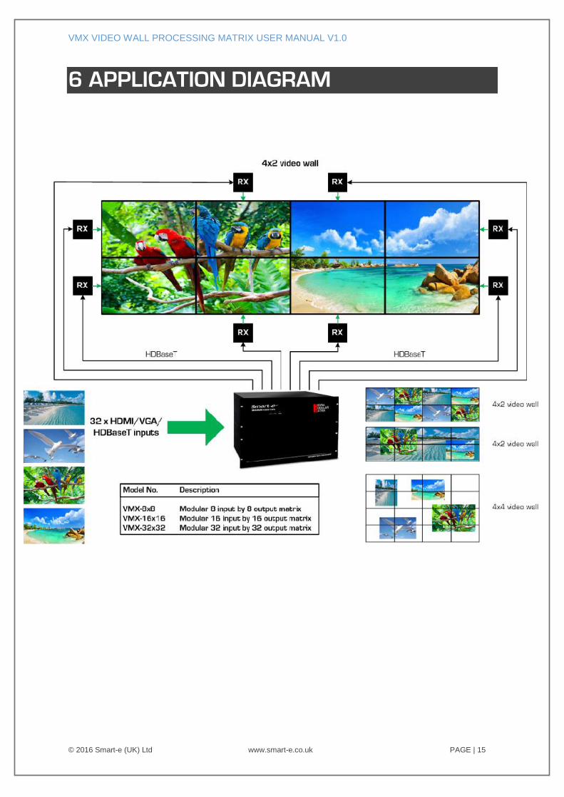
A range of modular matrix chassis, supporting 8x8, 16x16, 36x36 and 72x72 Input and Output
matrix switching
A range of Input Blades – each supporting 4x independent switchable input ports. Input Blades
are available for HDMI, DVI-D, Multi-format Analogue, HDBaseT, 3G-SDI and Fibre
A range of Output Blades – each supporting an array of 4 displays to create a Video Wall
independently switchable and scalable output ports. Output Blades are available for HDMI, DVI-
D, HDBaseT, 3G-SDI and Fibre
A range of accessories including active cooling fan-trays, ventilation panels, blank panels and a
redundant PSU
Input and Output Blades can be mixed & matched to provide the user with a diverse solution in a single
unified system.
DMM2 delivers analogue/digital hybrid capability – enabling the input of multi-format analogue video
(VGA/RGBHV, Component-video YPbPr, S-video and Composite-video) sources to digital output (HDMI, DVI-D
and HDBaseT). Analogue video is digitised and up-scaled as required up to HD 1080p.
The HDMI and DVI Input Blades provide active-input ports, enabling the installer to connect extended cable
lengths ≤15-meters.
The HDBaseT Input Blades enable remote connectivity to source devices fitted with a Smart-e 4K-TX866
Transmitter (or other compliant HDBaseT transmitter) ≤100-meters over copper twisted pair cable. 24V
power is supplied from the matrix to the transmitter through the twisted pair cabling.
The HDBaseT Output Blades enable remote connectivity to display devices fitted with a Smart-e 4K-RX866
Receiver (or other compliant HDBaseT receiver) ≤100-meters over copper twisted pair cable. 24V power is
supplied from the matrix to the transmitter through the twisted pair cabling.
Digital signal processing technology ensures that signals are transported without distortion and the best
quality output is transmitted to the display device. Each output port can have its resolution set to match that
of the connected screen ensuring best quality picture and seamless switching between inputs.
The matrix switching of VMX Blade Inputs/Outputs fully supports bi-directional RS232 control and bi-
directional Infrared control pass-through enabling control connectivity between remote source and display
devices.
The VMX matrices can be controlled by a variety of methods including:
Remote control, via Key Pad accessory.
Remote control via RS232 serial command
Remote control via TCP/IP Ethernet
Control via Smart-iP Interface (separate 1U chassis)
VMX VIDEO WALL PROCESSING MATRIX USER MANUAL V1.0
© 2016 Smart-e (UK) Ltd www.smart-e.co.uk PAGE | 6
2 FEATURES
19-inch Rack Mountable Form Factor.
Chassis versions to support 8x8, 16x16, 36x36 and 72x72 matrices.
Modular design enables variety of Input / Output blades to be populated within the matrix chassis.
Input blades have 4x individually selectable input ports per blade.
Output blades have 4x individually selectable output ports per blade.
Supports multiple format input –
o HDMI
o DVI-D
o Analogue (RGBHV, Component, Composite)
o HDBaseT
o 3G-SDI
o Fibre
Supports multiple format output –
o HDMI
o DVI-D
o Analogue (RGBHV, Component, Composite)
o HDBaseT
o 3G-SDI
o Fibre
Full seamless digital switching between inputs/outputs.
Digitising and up-scaling of analogue input sources
Supports switch throughput of HDBaseT control (RS232 bi-directional, Infrared bi-directional)
Fast channel switching for DVI 1.0 and HDMI 1.4
HDMI HDCP compatible
HDMI CEC compliant
External control via RS232 serial.
External control via TCP/IP.
Supports control via Smart-e web interface software, Smart-iP.
Integrated cooling fan system (with manual activation temperature settings).
Dual redundant power supply.
VMX VIDEO WALL PROCESSING MATRIX USER MANUAL V1.0
© 2016 Smart-e (UK) Ltd www.smart-e.co.uk PAGE | 7
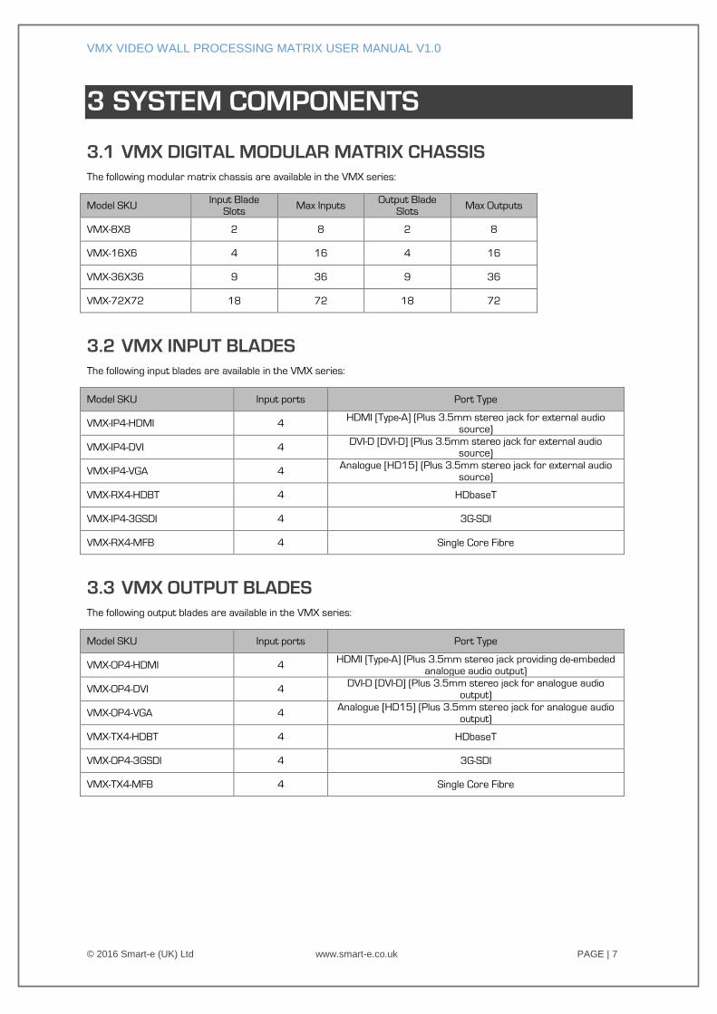
3 SYSTEM COMPONENTS
3.1 VMX DIGITAL MODULAR MATRIX CHASSIS
The following modular matrix chassis are available in the VMX series:
Model SKU Input Blade
Slots Max Inputs
Output Blade Slots
Max Outputs
VMX-8X8 2 8 2 8
VMX-16X6 4 16 4 16
VMX-36X36 9 36 9 36
VMX-72X72 18 72 18 72
3.2 VMX INPUT BLADES
The following input blades are available in the VMX series:
Model SKU Input ports Port Type
VMX-IP4-HDMI 4 HDMI [Type-A] (Plus 3.5mm stereo jack for external audio
source)
VMX-IP4-DVI 4 DVI-D [DVI-D] (Plus 3.5mm stereo jack for external audio
source)
VMX-IP4-VGA 4 Analogue [HD15] (Plus 3.5mm stereo jack for external audio
source)
VMX-RX4-HDBT 4 HDbaseT
VMX-IP4-3GSDI 4 3G-SDI
VMX-RX4-MFB 4 Single Core Fibre
3.3 VMX OUTPUT BLADES
The following output blades are available in the VMX series:
Model SKU Input ports Port Type
VMX-OP4-HDMI 4 HDMI [Type-A] (Plus 3.5mm stereo jack providing de-embeded
analogue audio output)
VMX-OP4-DVI 4 DVI-D [DVI-D] (Plus 3.5mm stereo jack for analogue audio
output)
VMX-OP4-VGA 4 Analogue [HD15] (Plus 3.5mm stereo jack for analogue audio
output)
VMX-TX4-HDBT 4 HDbaseT
VMX-OP4-3GSDI 4 3G-SDI
VMX-TX4-MFB 4 Single Core Fibre
VMX VIDEO WALL PROCESSING MATRIX USER MANUAL V1.0
© 2016 Smart-e (UK) Ltd www.smart-e.co.uk PAGE | 8
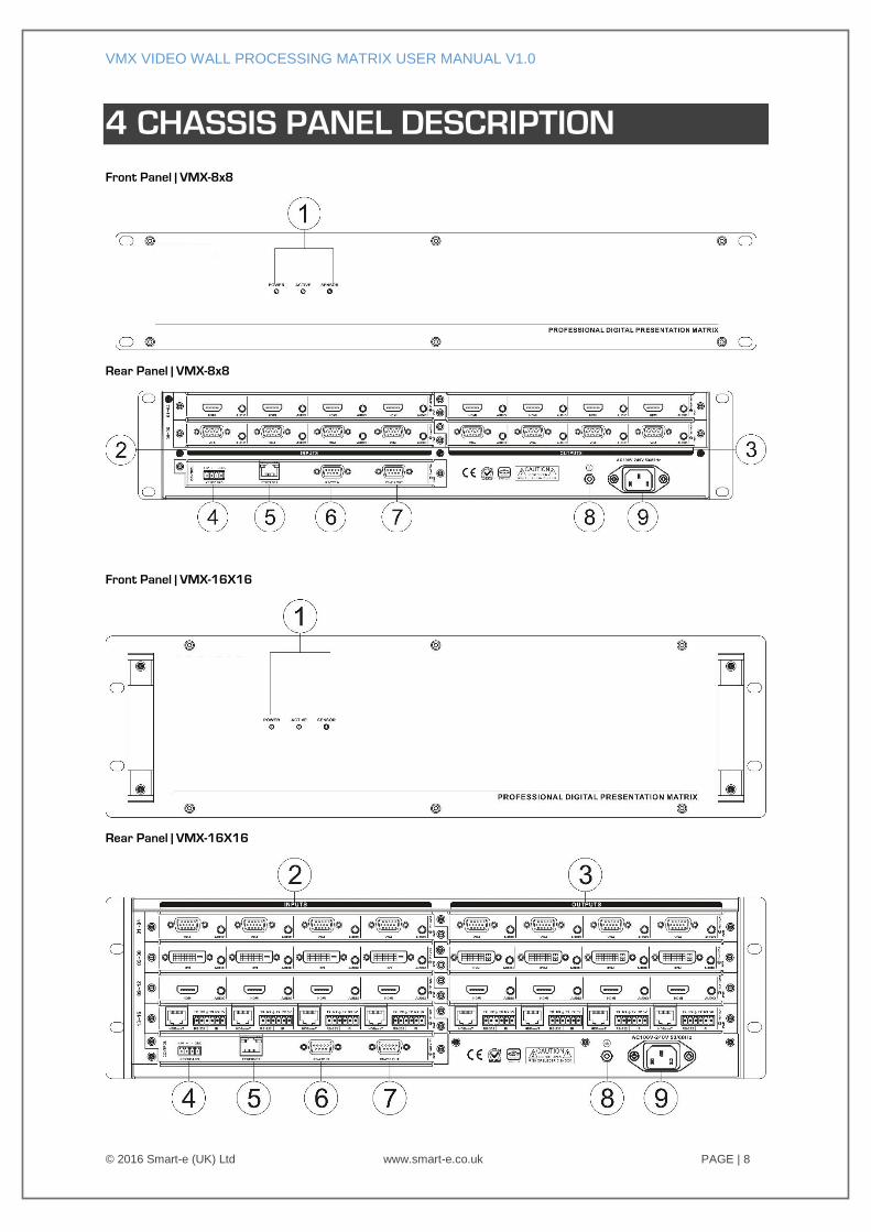
4 CHASSIS PANEL DESCRIPTION
Front Panel | VMX-8x8
Rear Panel | VMX-8x8
Front Panel | VMX-16X16
Rear Panel | VMX-16X16
VMX VIDEO WALL PROCESSING MATRIX USER MANUAL V1.0
© 2016 Smart-e (UK) Ltd www.smart-e.co.uk PAGE | 9
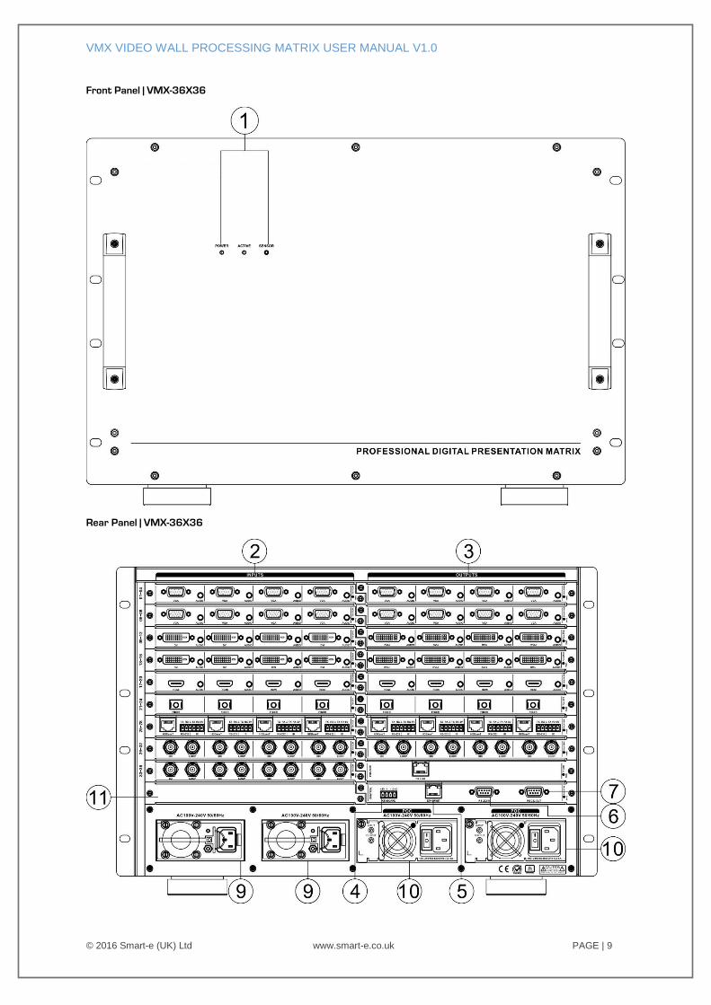
Front Panel | VMX-36X36
Rear Panel | VMX-36X36
VMX VIDEO WALL PROCESSING MATRIX USER MANUAL V1.0
© 2016 Smart-e (UK) Ltd www.smart-e.co.uk PAGE | 10
1 FRONT PANEL INDICATORS
Power LED – Solidly Lit Green When Power Supplies Operating Correctly
Active LED – Pulses Amber When Internal Processor Is Running
Sensor – Infrared Sensor to Control Matrix Functionality
2 INPUT PORTS
Location of VMX Input Blades
3 OUTPUT PORTS
Location of VMX Output Blades
4 KEYPAD CONTROL INPUT
4-way input for control keypad
5 ETHERNET PORT
Ethernet port enabling connection of matrix to LAN and allowing control over TCP/IP
6 D9 CONNECTOR – RS232 In Control Port
Used to connect VMX to control system (PC/SmartiP/3rd Party Controller)
7 D9 CONNECTOR – RS232 Out Port
Can be used to interconnect control systems where feedback or status is required from the VMX
8 EARTHING POINT
9 SYSTEM IEC INLETS
Power supply inlets to power the internal boards of the VMX (AC 100 – 240V 50/60Hz)
10 POC IEC MAINS INLETS
Power supply inlets to power remote transmitter and receiver units (TX/RX 4K-866s – 24V)
11 BLANK SOCKET – NO BLADE CAN BE INSERTED IN THIS SLOT
12 INFRARED SWITCH SLOT – Contact Smart-e for More info on Infrared Applications
VMX VIDEO WALL PROCESSING MATRIX USER MANUAL V1.0
© 2016 Smart-e (UK) Ltd www.smart-e.co.uk PAGE | 11
5 INPUT / OUTPUT BLADES
5.1 INPUT BLADES
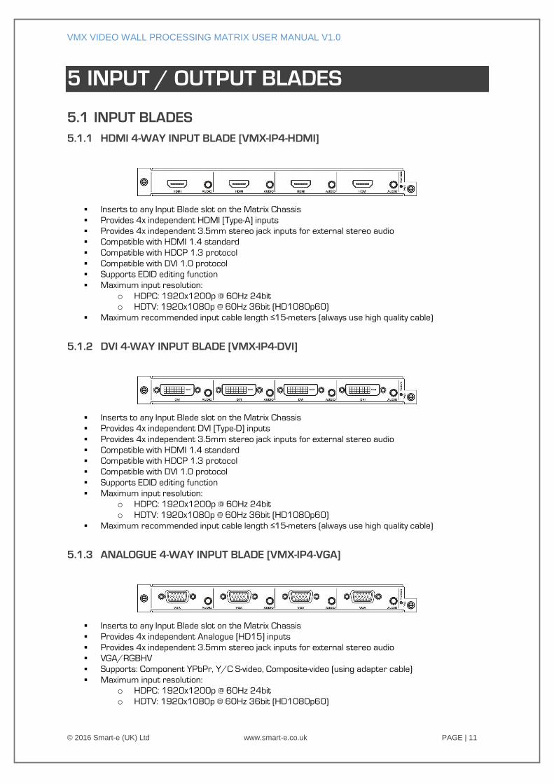
5.1.1 HDMI 4-WAY INPUT BLADE [VMX-IP4-HDMI]
Inserts to any Input Blade slot on the Matrix Chassis
Provides 4x independent HDMI [Type-A] inputs
Provides 4x independent 3.5mm stereo jack inputs for external stereo audio
Compatible with HDMI 1.4 standard
Compatible with HDCP 1.3 protocol
Compatible with DVI 1.0 protocol
Supports EDID editing function
Maximum input resolution:
o HDPC: 1920x1200p @ 60Hz 24bit
o HDTV: 1920x1080p @ 60Hz 36bit (HD1080p60)
Maximum recommended input cable length ≤15-meters (always use high quality cable)
5.1.2 DVI 4-WAY INPUT BLADE [VMX-IP4-DVI]
Inserts to any Input Blade slot on the Matrix Chassis
Provides 4x independent DVI [Type-D] inputs
Provides 4x independent 3.5mm stereo jack inputs for external stereo audio
Compatible with HDMI 1.4 standard
Compatible with HDCP 1.3 protocol
Compatible with DVI 1.0 protocol
Supports EDID editing function
Maximum input resolution:
o HDPC: 1920x1200p @ 60Hz 24bit
o HDTV: 1920x1080p @ 60Hz 36bit (HD1080p60)
Maximum recommended input cable length ≤15-meters (always use high quality cable)
5.1.3 ANALOGUE 4-WAY INPUT BLADE [VMX-IP4-VGA]
Inserts to any Input Blade slot on the Matrix Chassis
Provides 4x independent Analogue [HD15] inputs
Provides 4x independent 3.5mm stereo jack inputs for external stereo audio
VGA/RGBHV
Supports: Component YPbPr, Y/C S-video, Composite-video (using adapter cable)
Maximum input resolution:
o HDPC: 1920x1200p @ 60Hz 24bit
o HDTV: 1920x1080p @ 60Hz 36bit (HD1080p60)
VMX VIDEO WALL PROCESSING MATRIX USER MANUAL V1.0
© 2016 Smart-e (UK) Ltd www.smart-e.co.uk PAGE | 12
Digitises and up-scales input resolution ≤1920x1080p @ 60Hz
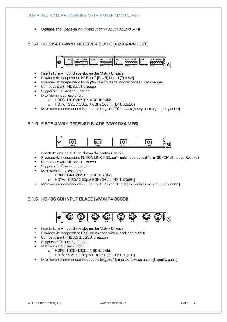
5.1.4 HDBASET 4-WAY RECEIVER BLADE [VMX-RX4-HDBT]
Inserts to any Input Blade slot on the Matrix Chassis
Provides 4x independent HDBaseT [RJ45] inputs (Receive)
Provides 4x independent full duplex RS232 serial connections (1 per channel)
Compatible with HDBaseT protocol
Supports EDID editing function
Maximum input resolution:
o HDPC: 1920x1200p @ 60Hz 24bit
o HDTV: 1920x1080p @ 60Hz 36bit (HD1080p60)
Maximum recommended input cable length ≤100-meters (always use high quality cable)
5.1.5 FIBRE 4-WAY RECEIVER BLADE [VMX-RX4-MFB]
Inserts to any Input Blade slot on the Matrix Chassis
Provides 4x independent FUSION LINK HDBaseT multimode optical fibre [SC/OM3] inputs (Receive)
Compatible with HDBaseT protocol
Supports EDID editing function
Maximum input resolution:
o HDPC: 1920x1200p @ 60Hz 24bit
o HDTV: 1920x1080p @ 60Hz 36bit (HD1080p60)
Maximum recommended input cable length ≤100-meters (always use high quality cable)
5.1.6 HD/3G SDI INPUT BLADE (VMX-IP4-3GSDI)
Inserts to any Input Blade slot on the Matrix Chassis
Provides 4x independent BNC inputs each with a local loop output
Compatible with HDSDI & 3GSDI protocols
Supports EDID editing function
Maximum input resolution:
o HDPC: 1920x1200p @ 60Hz 24bit
o HDTV: 1920x1080p @ 60Hz 36bit (HD1080p60)
Maximum recommended input cable length ≤15-meters (always use high quality cable)
VMX VIDEO WALL PROCESSING MATRIX USER MANUAL V1.0
© 2016 Smart-e (UK) Ltd www.smart-e.co.uk PAGE | 13
5.2 OUTPUT BLADES
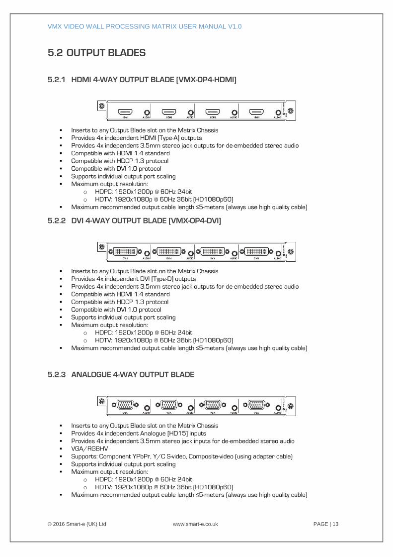
5.2.1 HDMI 4-WAY OUTPUT BLADE [VMX-OP4-HDMI]
Inserts to any Output Blade slot on the Matrix Chassis
Provides 4x independent HDMI [Type-A] outputs
Provides 4x independent 3.5mm stereo jack outputs for de-embedded stereo audio
Compatible with HDMI 1.4 standard
Compatible with HDCP 1.3 protocol
Compatible with DVI 1.0 protocol
Supports individual output port scaling
Maximum output resolution:
o HDPC: 1920x1200p @ 60Hz 24bit
o HDTV: 1920x1080p @ 60Hz 36bit (HD1080p60)
Maximum recommended output cable length ≤5-meters (always use high quality cable)
5.2.2 DVI 4-WAY OUTPUT BLADE [VMX-OP4-DVI]
Inserts to any Output Blade slot on the Matrix Chassis
Provides 4x independent DVI [Type-D] outputs
Provides 4x independent 3.5mm stereo jack outputs for de-embedded stereo audio
Compatible with HDMI 1.4 standard
Compatible with HDCP 1.3 protocol
Compatible with DVI 1.0 protocol
Supports individual output port scaling
Maximum output resolution:
o HDPC: 1920x1200p @ 60Hz 24bit
o HDTV: 1920x1080p @ 60Hz 36bit (HD1080p60)
Maximum recommended output cable length ≤5-meters (always use high quality cable)
5.2.3 ANALOGUE 4-WAY OUTPUT BLADE
Inserts to any Output Blade slot on the Matrix Chassis
Provides 4x independent Analogue [HD15] inputs
Provides 4x independent 3.5mm stereo jack inputs for de-embedded stereo audio
VGA/RGBHV
Supports: Component YPbPr, Y/C S-video, Composite-video (using adapter cable)
Supports individual output port scaling
Maximum output resolution:
o HDPC: 1920x1200p @ 60Hz 24bit
o HDTV: 1920x1080p @ 60Hz 36bit (HD1080p60)
Maximum recommended output cable length ≤5-meters (always use high quality cable)
VMX VIDEO WALL PROCESSING MATRIX USER MANUAL V1.0
© 2016 Smart-e (UK) Ltd www.smart-e.co.uk PAGE | 14
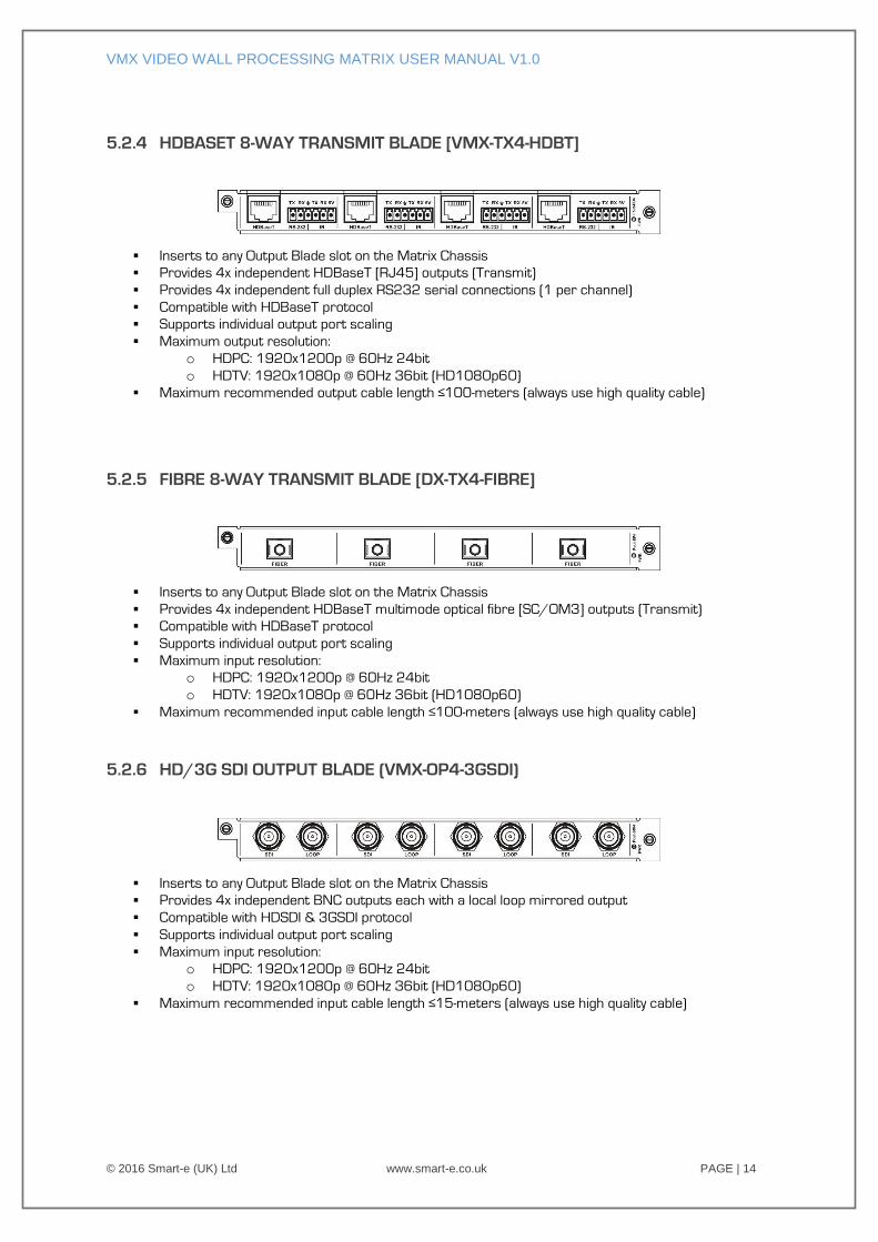
5.2.4 HDBASET 8-WAY TRANSMIT BLADE [VMX-TX4-HDBT]
Inserts to any Output Blade slot on the Matrix Chassis
Provides 4x independent HDBaseT [RJ45] outputs (Transmit)
Provides 4x independent full duplex RS232 serial connections (1 per channel)
Compatible with HDBaseT protocol
Supports individual output port scaling
Maximum output resolution:
o HDPC: 1920x1200p @ 60Hz 24bit
o HDTV: 1920x1080p @ 60Hz 36bit (HD1080p60)
Maximum recommended output cable length ≤100-meters (always use high quality cable)
5.2.5 FIBRE 8-WAY TRANSMIT BLADE [DX-TX4-FIBRE]
Inserts to any Output Blade slot on the Matrix Chassis
Provides 4x independent HDBaseT multimode optical fibre [SC/OM3] outputs (Transmit)
Compatible with HDBaseT protocol
Supports individual output port scaling
Maximum input resolution:
o HDPC: 1920x1200p @ 60Hz 24bit
o HDTV: 1920x1080p @ 60Hz 36bit (HD1080p60)
Maximum recommended input cable length ≤100-meters (always use high quality cable)
5.2.6 HD/3G SDI OUTPUT BLADE (VMX-OP4-3GSDI)
Inserts to any Output Blade slot on the Matrix Chassis
Provides 4x independent BNC outputs each with a local loop mirrored output
Compatible with HDSDI & 3GSDI protocol
Supports individual output port scaling
Maximum input resolution:
o HDPC: 1920x1200p @ 60Hz 24bit
o HDTV: 1920x1080p @ 60Hz 36bit (HD1080p60)
Maximum recommended input cable length ≤15-meters (always use high quality cable)
VMX VIDEO WALL PROCESSING MATRIX USER MANUAL V1.0
© 2016 Smart-e (UK) Ltd www.smart-e.co.uk PAGE | 15
6 APPLICATION DIAGRAM
VMX VIDEO WALL PROCESSING MATRIX USER MANUAL V1.0
© 2016 Smart-e (UK) Ltd www.smart-e.co.uk PAGE | 16
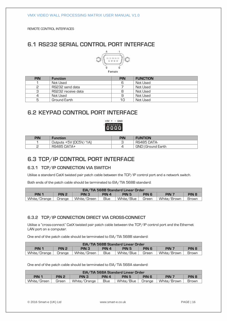
REMOTE CONTROL INTERFACES
6.1 RS232 SERIAL CONTROL PORT INTERFACE
PIN Function PIN FUNCTION
1 Not Used 6 Not Used
2 RS232 send data 7 Not Used
3 RS232 receive data 8 Not Used
4 Not Used 9 Not Used
5 Ground Earth 10 Not Used
6.2 KEYPAD CONTROL PORT INTERFACE
PIN Function PIN FUNTION
1 Outputs +5V (DC5V/1A) 3 RS485 DATA-
2 RS485 DATA+ 4 GND | Ground Earth
6.3 TCP/IP CONTROL PORT INTERFACE
6.3.1 TCP/IP CONNECTION VIA SWITCH
Utilise a standard CatX twisted pair patch cable between the TCP/IP control port and a network switch.
Both ends of the patch cable should be terminated to EIA/TIA 568B standard:
EIA/TIA 568B Standard Linear Order
PIN 1 PIN 2 PIN 3 PIN 4 PIN 5 PIN 6 PIN 7 PIN 8
White/Orange Orange White/Green Blue White/Blue Green White/Brown Brown
6.3.2 TCP/IP CONNECTION DIRECT VIA CROSS-CONNECT
Utilise a “cross-connect” CatX twisted pair patch cable between the TCP/IP control port and the Ethernet
LAN port on a computer.
One end of the patch cable should be terminated to EIA/TIA 568B standard:
EIA/TIA 568B Standard Linear Order
PIN 1 PIN 2 PIN 3 PIN 4 PIN 5 PIN 6 PIN 7 PIN 8
White/Orange Orange White/Green Blue White/Blue Green White/Brown Brown
One end of the patch cable should be terminated to EIA/TIA 568A standard:
EIA/TIA 568A Standard Linear Order
PIN 1 PIN 2 PIN 3 PIN 4 PIN 5 PIN 6 PIN 7 PIN 8
White/Green Green White/Orange Blue White/Blue Orange White/Brown Brown
VMX VIDEO WALL PROCESSING MATRIX USER MANUAL V1.0
© 2016 Smart-e (UK) Ltd www.smart-e.co.uk PAGE | 17
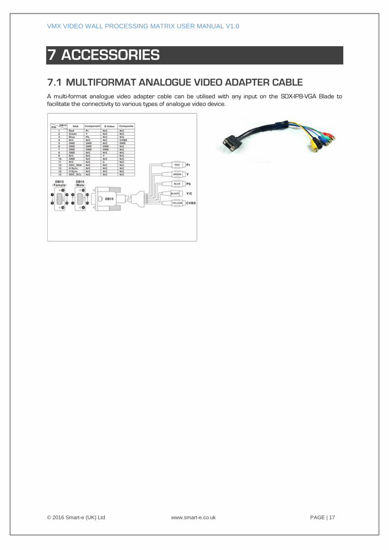
7 ACCESSORIES
7.1 MULTIFORMAT ANALOGUE VIDEO ADAPTER CABLE
A multi-format analogue video adapter cable can be utilised with any input on the SDX-IP8-VGA Blade to
facilitate the connectivity to various types of analogue video device.
VMX VIDEO WALL PROCESSING MATRIX USER MANUAL V1.0
© 2016 Smart-e (UK) Ltd www.smart-e.co.uk PAGE | 18
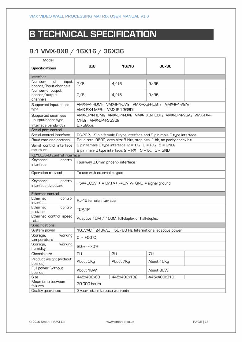
8 TECHNICAL SPECIFICATION
8.1 VMX-8X8 / 16X16 / 36X36
Model
Specifications 8x8 16x16 36x36
Interface
Number of input
boards/input channels 2/8 4/16 9/36
Number of output
boards/output
channels
2/8 4/16 9/36
Supported input board type
VMX-IP4-HDMI;VMX-IP4-DVI; VMX-RX8-HDBT; VMX-IP4-VGA;
VMX-RX4-MFB; VMX-IP4-3GSDI
Supported seamless
output board type
VMX-OP4-HDMI;VMX-OP4-DVI;VMX-TX8-HDBT;VMX-OP4-VGA;VMX-TX4-
MFB; VMX-OP4-3GSDI;
Interface bandwidth 6.75Gbps
Serial port control
Serial control interface RS-232,9 pin female D type interface and 9 pin male D type interface
Baud rate and protocol Baud rate: 9600, data bits: 8 bits, stop bits: 1 bit, no parity check bit
Serial control interface
structure
9 pin female D type interface: 2 = TX,3 = RX,5 = GND;
9 pin male D type interface: 2 = RX,3 =TX,5 = GND
KEYBOARD control interface
Keyboard control
interface Four-way 3.8mm phoenix interface
Operation method To use with external keypad
Keyboard control
interface structure +5V=DC5V, + = DATA+, -=DATA- GND = signal ground
Ethernet control
Ethernet control
interface RJ-45 female interface
Ethernet control protocol
TCP/IP
Ethernet control speed
rate Adaptive 10M / 100M, full-duplex or half-duplex
Specifications
System power 100VAC ~ 240VAC,50/60 Hz, International adaptive power
Storage, working temperature
0~ +50°C
Storage, working humidity
20% ~70%
Chassis size 2U 3U 7U
Product weight (without
boards) About 5Kg About 7Kg About 16Kg
Full power (without
boards) About 18W About 30W
Size 445x400x88 445x400x132 445x400x310
Mean time between
failures 30,000 hours
Quality guarantee 3-year return to base warranty
VMX VIDEO WALL PROCESSING MATRIX USER MANUAL V1.0
© 2016 Smart-e (UK) Ltd www.smart-e.co.uk PAGE | 19
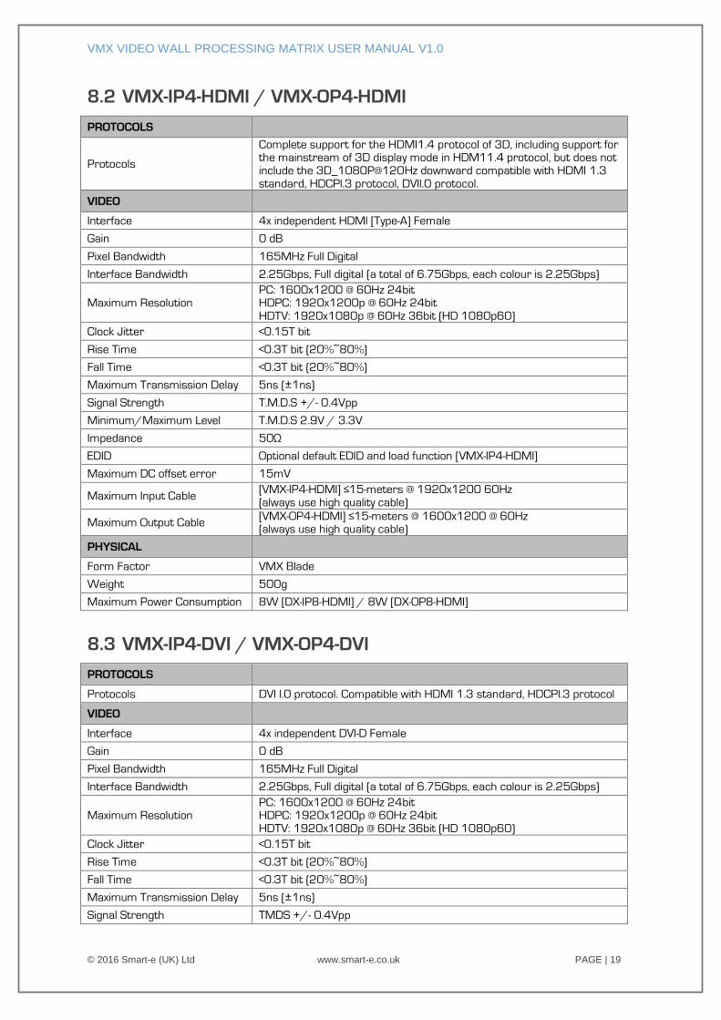
8.2 VMX-IP4-HDMI / VMX-OP4-HDMI
PROTOCOLS
Protocols
Complete support for the HDMI1.4 protocol of 3D, including support for the mainstream of 3D display mode in HDM11.4 protocol, but does not
include the 3D_1080P@120Hz downward compatible with HDMI 1.3
standard, HDCPl.3 protocol, DVIl.0 protocol.
VIDEO
Interface 4x independent HDMI [Type-A] Female
Gain 0 dB
Pixel Bandwidth 165MHz Full Digital
Interface Bandwidth 2.25Gbps, Full digital (a total of 6.75Gbps, each colour is 2.25Gbps)
Maximum Resolution PC: 1600x1200 @ 60Hz 24bit HDPC: 1920x1200p @ 60Hz 24bit
HDTV: 1920x1080p @ 60Hz 36bit (HD 1080p60)
Clock Jitter <0.15T bit
Rise Time <0.3T bit (20%~80%)
Fall Time <0.3T bit (20%~80%)
Maximum Transmission Delay 5ns (±1ns)
Signal Strength T.M.D.S +/- 0.4Vpp
Minimum/Maximum Level T.M.D.S 2.9V / 3.3V
Impedance 50Ω
EDID Optional default EDID and load function [VMX-IP4-HDMI]
Maximum DC offset error 15mV
Maximum Input Cable [VMX-IP4-HDMI] ≤15-meters @ 1920x1200 60Hz
(always use high quality cable)
Maximum Output Cable [VMX-OP4-HDMI] ≤15-meters @ 1600x1200 @ 60Hz (always use high quality cable)
PHYSICAL
Form Factor VMX Blade
Weight 500g
Maximum Power Consumption 8W [DX-IP8-HDMI] / 8W [DX-OP8-HDMI]
8.3 VMX-IP4-DVI / VMX-OP4-DVI
PROTOCOLS
Protocols DVI l.0 protocol. Compatible with HDMI 1.3 standard, HDCPl.3 protocol
VIDEO
Interface 4x independent DVI-D Female
Gain 0 dB
Pixel Bandwidth 165MHz Full Digital
Interface Bandwidth 2.25Gbps, Full digital (a total of 6.75Gbps, each colour is 2.25Gbps)
Maximum Resolution PC: 1600x1200 @ 60Hz 24bit HDPC: 1920x1200p @ 60Hz 24bit
HDTV: 1920x1080p @ 60Hz 36bit (HD 1080p60)
Clock Jitter <0.15T bit
Rise Time <0.3T bit (20%~80%)
Fall Time <0.3T bit (20%~80%)
Maximum Transmission Delay 5ns (±1ns)
Signal Strength TMDS +/- 0.4Vpp
VMX VIDEO WALL PROCESSING MATRIX USER MANUAL V1.0
© 2016 Smart-e (UK) Ltd www.smart-e.co.uk PAGE | 20
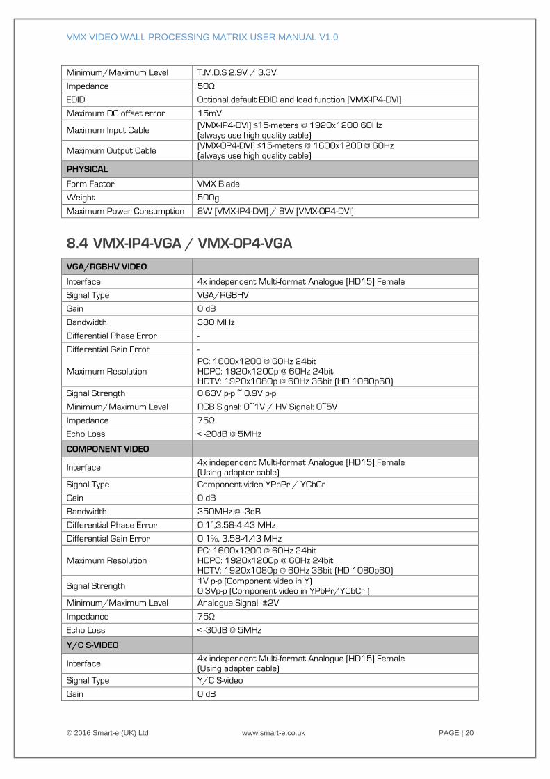
Minimum/Maximum Level T.M.D.S 2.9V / 3.3V
Impedance 50Ω
EDID Optional default EDID and load function [VMX-IP4-DVI]
Maximum DC offset error 15mV
Maximum Input Cable [VMX-IP4-DVI] ≤15-meters @ 1920x1200 60Hz
(always use high quality cable)
Maximum Output Cable [VMX-OP4-DVI] ≤15-meters @ 1600x1200 @ 60Hz (always use high quality cable)
PHYSICAL
Form Factor VMX Blade
Weight 500g
Maximum Power Consumption 8W [VMX-IP4-DVI] / 8W [VMX-OP4-DVI]
8.4 VMX-IP4-VGA / VMX-OP4-VGA
VGA/RGBHV VIDEO
Interface 4x independent Multi-format Analogue [HD15] Female
Signal Type VGA/RGBHV
Gain 0 dB
Bandwidth 380 MHz
Differential Phase Error -
Differential Gain Error -
Maximum Resolution
PC: 1600x1200 @ 60Hz 24bit
HDPC: 1920x1200p @ 60Hz 24bit HDTV: 1920x1080p @ 60Hz 36bit (HD 1080p60)
Signal Strength 0.63V p-p ~ 0.9V p-p
Minimum/Maximum Level RGB Signal: 0~1V / HV Signal: 0~5V
Impedance 75Ω
Echo Loss < -20dB @ 5MHz
COMPONENT VIDEO
Interface 4x independent Multi-format Analogue [HD15] Female
(Using adapter cable)
Signal Type Component-video YPbPr / YCbCr
Gain 0 dB
Bandwidth 350MHz @ -3dB
Differential Phase Error 0.1°,3.58-4.43 MHz
Differential Gain Error 0.1%, 3.58-4.43 MHz
Maximum Resolution
PC: 1600x1200 @ 60Hz 24bit
HDPC: 1920x1200p @ 60Hz 24bit HDTV: 1920x1080p @ 60Hz 36bit (HD 1080p60)
Signal Strength 1V p-p (Component video in Y)
0.3Vp-p (Component video in YPbPr/YCbCr )
Minimum/Maximum Level Analogue Signal: ±2V
Impedance 75Ω
Echo Loss < -30dB @ 5MHz
Y/C S-VIDEO
Interface 4x independent Multi-format Analogue [HD15] Female (Using adapter cable)
Signal Type Y/C S-video
Gain 0 dB
VMX VIDEO WALL PROCESSING MATRIX USER MANUAL V1.0
© 2016 Smart-e (UK) Ltd www.smart-e.co.uk PAGE | 21
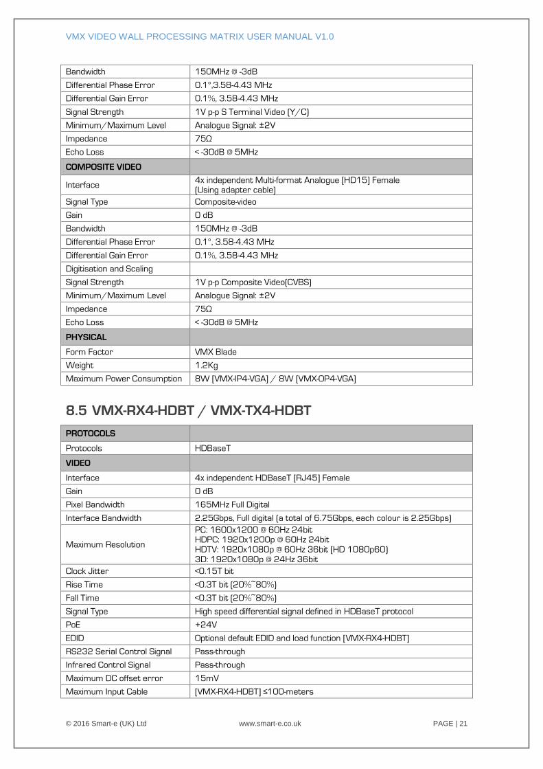
Bandwidth 150MHz @ -3dB
Differential Phase Error 0.1°,3.58-4.43 MHz
Differential Gain Error 0.1%, 3.58-4.43 MHz
Signal Strength 1V p-p S Terminal Video (Y/C)
Minimum/Maximum Level Analogue Signal: ±2V
Impedance 75Ω
Echo Loss < -30dB @ 5MHz
COMPOSITE VIDEO
Interface 4x independent Multi-format Analogue [HD15] Female (Using adapter cable)
Signal Type Composite-video
Gain 0 dB
Bandwidth 150MHz @ -3dB
Differential Phase Error 0.1°, 3.58-4.43 MHz
Differential Gain Error 0.1%, 3.58-4.43 MHz
Digitisation and Scaling
Signal Strength 1V p-p Composite Video(CVBS)
Minimum/Maximum Level Analogue Signal: ±2V
Impedance 75Ω
Echo Loss < -30dB @ 5MHz
PHYSICAL
Form Factor VMX Blade
Weight 1.2Kg
Maximum Power Consumption 8W [VMX-IP4-VGA] / 8W [VMX-OP4-VGA]
8.5 VMX-RX4-HDBT / VMX-TX4-HDBT
PROTOCOLS
Protocols HDBaseT
VIDEO
Interface 4x independent HDBaseT [RJ45] Female
Gain 0 dB
Pixel Bandwidth 165MHz Full Digital
Interface Bandwidth 2.25Gbps, Full digital (a total of 6.75Gbps, each colour is 2.25Gbps)
Maximum Resolution
PC: 1600x1200 @ 60Hz 24bit HDPC: 1920x1200p @ 60Hz 24bit
HDTV: 1920x1080p @ 60Hz 36bit (HD 1080p60)
3D: 1920x1080p @ 24Hz 36bit
Clock Jitter <0.15T bit
Rise Time <0.3T bit (20%~80%)
Fall Time <0.3T bit (20%~80%)
Signal Type High speed differential signal defined in HDBaseT protocol
PoE +24V
EDID Optional default EDID and load function [VMX-RX4-HDBT]
RS232 Serial Control Signal Pass-through
Infrared Control Signal Pass-through
Maximum DC offset error 15mV
Maximum Input Cable [VMX-RX4-HDBT] ≤100-meters
VMX VIDEO WALL PROCESSING MATRIX USER MANUAL V1.0
© 2016 Smart-e (UK) Ltd www.smart-e.co.uk PAGE | 22
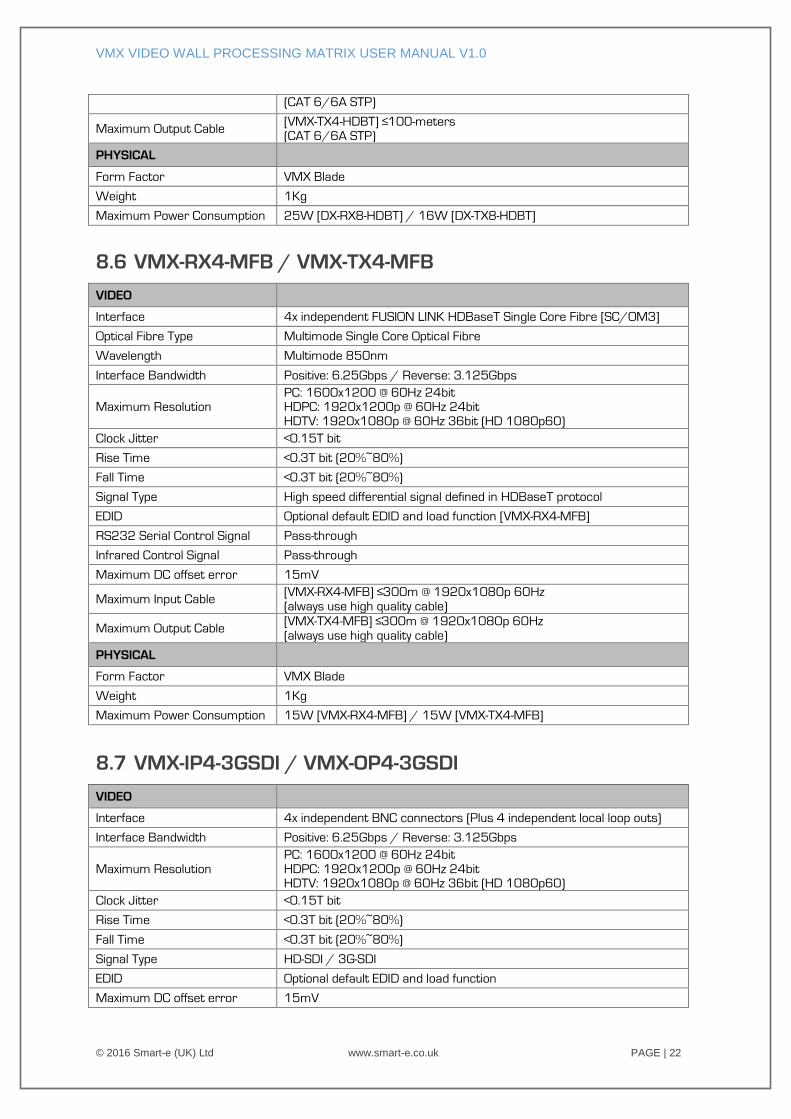
(CAT 6/6A STP)
Maximum Output Cable [VMX-TX4-HDBT] ≤100-meters
(CAT 6/6A STP)
PHYSICAL
Form Factor VMX Blade
Weight 1Kg
Maximum Power Consumption 25W [DX-RX8-HDBT] / 16W [DX-TX8-HDBT]
8.6 VMX-RX4-MFB / VMX-TX4-MFB
VIDEO
Interface 4x independent FUSION LINK HDBaseT Single Core Fibre [SC/OM3]
Optical Fibre Type Multimode Single Core Optical Fibre
Wavelength Multimode 850nm
Interface Bandwidth Positive: 6.25Gbps / Reverse: 3.125Gbps
Maximum Resolution PC: 1600x1200 @ 60Hz 24bit HDPC: 1920x1200p @ 60Hz 24bit
HDTV: 1920x1080p @ 60Hz 36bit (HD 1080p60)
Clock Jitter <0.15T bit
Rise Time <0.3T bit (20%~80%)
Fall Time <0.3T bit (20%~80%)
Signal Type High speed differential signal defined in HDBaseT protocol
EDID Optional default EDID and load function [VMX-RX4-MFB]
RS232 Serial Control Signal Pass-through
Infrared Control Signal Pass-through
Maximum DC offset error 15mV
Maximum Input Cable [VMX-RX4-MFB] ≤300m @ 1920x1080p 60Hz
(always use high quality cable)
Maximum Output Cable [VMX-TX4-MFB] ≤300m @ 1920x1080p 60Hz
(always use high quality cable)
PHYSICAL
Form Factor VMX Blade
Weight 1Kg
Maximum Power Consumption 15W [VMX-RX4-MFB] / 15W [VMX-TX4-MFB]
8.7 VMX-IP4-3GSDI / VMX-OP4-3GSDI
VIDEO
Interface 4x independent BNC connectors (Plus 4 independent local loop outs)
Interface Bandwidth Positive: 6.25Gbps / Reverse: 3.125Gbps
Maximum Resolution
PC: 1600x1200 @ 60Hz 24bit
HDPC: 1920x1200p @ 60Hz 24bit HDTV: 1920x1080p @ 60Hz 36bit (HD 1080p60)
Clock Jitter <0.15T bit
Rise Time <0.3T bit (20%~80%)
Fall Time <0.3T bit (20%~80%)
Signal Type HD-SDI / 3G-SDI
EDID Optional default EDID and load function
Maximum DC offset error 15mV
VMX VIDEO WALL PROCESSING MATRIX USER MANUAL V1.0
© 2016 Smart-e (UK) Ltd www.smart-e.co.uk PAGE | 23
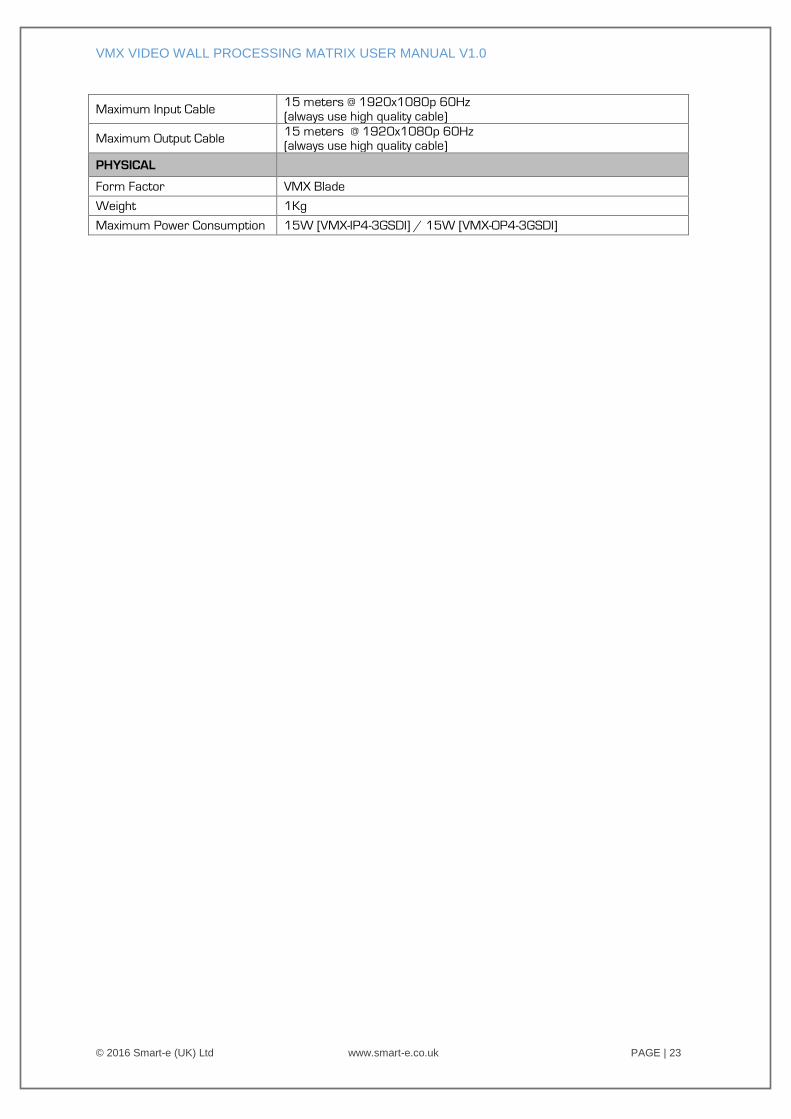
Maximum Input Cable 15 meters @ 1920x1080p 60Hz
(always use high quality cable)
Maximum Output Cable 15 meters @ 1920x1080p 60Hz (always use high quality cable)
PHYSICAL
Form Factor VMX Blade
Weight 1Kg
Maximum Power Consumption 15W [VMX-IP4-3GSDI] / 15W [VMX-OP4-3GSDI]