VMA1891rev2 - Clarion4 OSD Operation VMA1891 18.1Ó TFT LCD Color Monitor OSD OPERATIONDESCRIPTIONS:...
12
18.1” TFT LCD COLOR MONITOR OWNER’S MANUAL INSTALLATION GUIDE VMA1891
Transcript of VMA1891rev2 - Clarion4 OSD Operation VMA1891 18.1Ó TFT LCD Color Monitor OSD OPERATIONDESCRIPTIONS:...
18.1” TFT LCD COLOR
M O N I T O R
OWNER’S MANUAL
INSTALLATION GUIDE
VMA1891


1
Intro
du
ctio
nOWNER’S MANUAL
INTRODUCTION:The Clarion VMA1891 is a full-featured 18.1" TFT LCD Color Monitor. It can beused as:• A stand-alone monitor with a home PC or Laptop Computer.• A monitor integrated into a Clarion mobile multimedia system using auxiliary
built-in Video Composite (RCA) or S-Video inputs.• A mobile PC monitor through the VGA input.ABOUT THE MANUAL AND WARRANTY:To start enjoying your new Clarion VMA1891, please read the instructions listedin this manual. Keep all instructions for future reference. Please fill out and sendin the enclosed warranty card to protect your purchase and aid in warranty service.Also, save your original sales receipt as proof of purchase.
NOTE: When using the VMA1891 with other Clarion multimedia products,please refer to their separate owner’s manuals for operating procedures.
TABLE OF CONTENTS:INTRODUCTION . . . . . . . . . . . . . . . . . . . . . . . . . . . . . . . . . . . . . . 1PRECAUTIONS . . . . . . . . . . . . . . . . . . . . . . . . . . . . . . . . . . . . . . .1PACKAGE CONTENTS . . . . . . . . . . . . . . . . . . . . . . . . . . . . . . . . . .2CONTROL DESCRIPTION AND BUTTON LOCATIONS . . . . . . . . . . . . . . . . . .2REAR CONTROLS AND CONNECTOR LOCATIONS . . . . . . . . . . . . . . . . . . . .3OPERATION DESCRIPTIONS . . . . . . . . . . . . . . . . . . . . . . . . . . . . . . . .3OSD OPERATION DESCRIPTIONS . . . . . . . . . . . . . . . . . . . . . . . . . . . .4CARE AND MAINTENANCE . . . . . . . . . . . . . . . . . . . . . . . . . . . . . . . .5110VAC HOME APPLICATIONS . . . . . . . . . . . . . . . . . . . . . . . . . . . . .6WIRING PRECAUTIONS (+12V OPERATION) . . . . . . . . . . . . . . . . . . . . .712VDC APPLICATIONS . . . . . . . . . . . . . . . . . . . . . . . . . . . . . . . . . .7ABOUT INSTALLATION . . . . . . . . . . . . . . . . . . . . . . . . . . . . . . . . . . .8SPECIFICATIONS & TROUBLESHOOTING . . . . . . . . . . . . . . . . . . . . . . . . .9
PRECAUTIONS:• This set can be use in 12V, negative ground vehicles or home applications. Be
sure to consult your Clarion Dealer before installing it in 24V vehicles.• Do not operate the set in ways other than described in this guide. Doing so may
damage it.• SAFETY FIRST! For rear seat use only. Do not install anywhere that permits
viewing by the driver. Monitor must not be located in a motor vehicle at anypoint forward of the back of the front seats. Monitor must never be used in anymanner that will distract or interfere with driver’s safe operation of the vehicle.
• Be careful not to run down the car battery while using the set with the carstopped.
• For safety, install the set in a position at which the driver cannot see it.
• Do not disassemble or modify the set. Doing so may damage it and voids yourwarranty.
• Keep drinks and drops from umbrellas away from the set. Water may damagethe internal circuitry.
• Do not let the set become hot. If temperature in the car is high or the set hasbeen exposed to direct sunlight and is hot, lower the temperature before usingit. (The liquid crystal panel will work properly within a temperature range of30 – 113 degrees F.)
• In extremely cold temperatures, the movement of the picture may be slow andthe picture may be dark. This is not a malfunction. The set will work normallyonce the temperature increases.
• Small black and shiny dots inside the liquid crystal panel are normal for liquidcrystal products.
PACKAGE CONTENTS:The Clarion VMA1891 comes with the following items:• RGB Cable for PC or Laptop Connection• Video RCA Connector• Three Conductor AC Power Cord• 3.5 mm Stereo Jack to Stereo RCA adapter
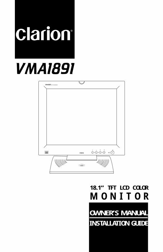
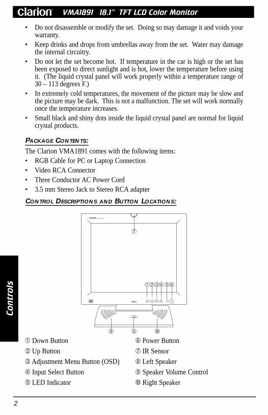
CONTROL DESCRIPTIONS AND BUTTON LOCATIONS:
2
Co
ntr
ols
VMA1891 18.1” TFT LCD Color Monitor
1 Down Button
2 Up Button
3 Adjustment Menu Button (OSD)
4 Input Select Button
5 LED Indicator
6 Power Button
7 IR Sensor
8 Left Speaker
9 Speaker Volume Control
0 Right Speaker
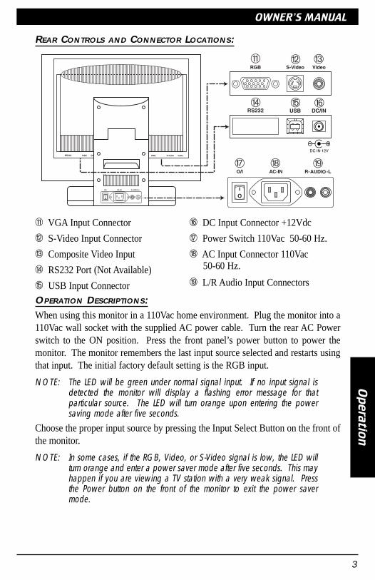
REAR CONTROLS AND CONNECTOR LOCATIONS:
OPERATION DESCRIPTIONS:When using this monitor in a 110Vac home environment. Plug the monitor into a110Vac wall socket with the supplied AC power cable. Turn the rear AC Powerswitch to the ON position. Press the front panel’s power button to power themonitor. The monitor remembers the last input source selected and restarts usingthat input. The initial factory default setting is the RGB input.
NOTE: The LED will be green under normal signal input. If no input signal isdetected the monitor will display a flashing error message for thatparticular source. The LED will turn orange upon entering the powersaving mode after five seconds.
Choose the proper input source by pressing the Input Select Button on the front ofthe monitor.
NOTE: In some cases, if the RGB, Video, or S-Video signal is low, the LED willturn orange and enter a power saver mode after five seconds. This mayhappen if you are viewing a TV station with a very weak signal. Pressthe Power button on the front of the monitor to exit the power savermode.
3
Op
era
tion
OWNER’S MANUAL
q VGA Input Connector
w S-Video Input Connector
e Composite Video Input
r RS232 Port (Not Available)
t USB Input Connector
y DC Input Connector +12Vdc
u Power Switch 110Vac 50-60 Hz.
i AC Input Connector 110Vac50-60 Hz.
o L/R Audio Input Connectors

4
OS
DO
pe
rati
on
VMA1891 18.1” TFT LCD Color Monitor
OSD OPERATION DESCRIPTIONS:1. Press the OSD Menu button 3 to display the on-screen menu. Press the UP2
or DN 1 button to scroll forward or backwards for each monitor settings.2. Press the OSD Menu button 3 again to select the function. See list below for
individual function operations.
Brightness Use UP/DN buttons to increase or decreasethe level. Press the OSD display button twiceto exit the function.
None
OSD FUNCTIONS AND OPERATIONS:Icons Sub Menus Function Operation
Intensity of white light.
Contrast Use UP/DN buttons to increase or decreasethe level. Press the OSD display button twiceto exit the function.
None Ratio of black to whiteintensity.
Color Use UP/DN buttons to select the adjustmentSub Menu. Press the OSD button again. Usethe UP/DN buttons to increase or decrease thelevel. Press the OSD display button to saveand exit to the Main Menu.
1) Red2) Green3) Blue
Intensity of Red colorIntensity of Green colorIntensity of Blue color
Position &Quality
Use UP/DN buttons to select the adjustmentSub Menu. Press the OSD button again. Usethe UP/DN buttons to increase or decreasethe level. Press the OSD display button tosave and exit to the Main Menu.
1) H-Position2) V-Position3) Frequency4) Phase
Horizontal screen positionVertical screen positionVertical flickerHorizontal flicker
Recall Use UP/DN buttons to select the adjustmentSub Menu. Press the OSD button again. Usethe UP/DN buttons to select choice. Press theOSD button again to save. Select Exit, thenpress the OSD button to exit the Main Menu.
1)Factory settingYes/No
2) 9300° K3) 6300° K4) Exit
Recalls the factory settings
Chromaticity coordinateaccording to CIE 1931.Exits Function
96

TILTING THE MONITOR:Gently hold the top and bottom of the monitor panel and tilt the monitor forwardor backwards to achieve the desired viewing angle. Maximum tilt angle is 10°forward and up to 45° backwards.
CARE AND MAINTENANCE:Cleaning the cabinet:• Use a soft, dry cloth and gently wipe off any dirt. For tough dirt, apply some
neutral detergent diluted in water to a soft cloth, wipe off the dirt gently, thenwipe again with a dry cloth.
• Do not use liquid cleaners on any surfaces as they may damage the cabinet orcause the paint to peel. Also leaving rubber or plastic products in contact withthe cabinet for long periods of time may cause stains.
Cleaning the LCD Panel• The LCD panel tends to collect dust, so wipe it off occasionally with a soft dry
cloth. The surface is easily scratched; so wipe with gentle light strokes.• Do not use any type of hard objects to clean the surface. Damage may occur.
5
OS
DF
un
ctio
ns
OWNER’S MANUAL
AutoAdjust
Use UP/DN buttons to select the appropriateSub Menu. Press the OSD display button toactivate the automatic function. Select Exit,then press the OSD button to exit the function
1) All2) Auto Position3) Auto Phase4) Exit
Auto Sets all functionsAuto Screen PositionAuto Phase settingsExits and Auto Saves
InputSource
Use UP/DN buttons to select the appropriateSub Menu. Press the OSD display button toenter the input type. If no signal is present,an error message will appear.
1) RGB2) Video (RCA)3) S-Video
Input for PCInput for Composite VideoInput for High qualityvideo (such as DVD)
DisplaySize
Use UP/DN buttons to select any adjustmentSub Menu. Press the OSD display button tosave choice. Use UP/DN buttons to scroll toExit in Main Menu. Press OSD button to exit
1) Normal2) Expand3) Full
Normal 4/3 ModeWidescreen mode 16/9Fills the height and widthof the screen
Language Use the UP/DN buttons to select theappropriate language. Press the OSD displaybutton again to save the language and exit tothe Main Menu.
1) English2) German3) French4) Italian5) Spanish
Changes the OSD menu tothe user’s preferredlanguage.
OSDControl
Use UP/DN buttons to select the appropriateSub Menu. Press the OSD display button toenter the Sub Menu. Use the UP/DN buttonto scroll through the adjustment choices.Press the OSD display button to save theadjustment. Select Exit and press the OSDdisplay button to exit to the Main Menu.
1) OSD Timeout2) OSD Position3) OSD Color
4) Exit
15, 30, 45, 60 secondsHor. or Ver. PositionBlue, Green, Cyan, Ma-genta, NoneExits and Auto Saves
Exit Use UP/DN buttons to select the Exitfunction. Press the OSD display button againto exit the Main Menu.
None Saves and Exits MainMenu. If OSD Timeout isactivated, the menu willdisappear after timeout.
OSD FUNCTIONS AND OPERATIONS:Icons Sub Menus Function Operation

110 VAC HOME APPLICATION:
Attaching a home VCR player.1. Connect the L/R audio outputs of the VCR player to the R-AUDIO-L inputs.2. Connect the video output to the Video input on the VMA1891.
NOTE: Since there is only one set of L/R audio inputs on the VMA1891,additional components must route their audio signals through the VCRA/V inputs. This may limit the components attached to the VMA1891.
Attaching a home computer or laptop.1. Connect the computer’s audio output (through the provided adapter cable) into
the R-AUDIO-L inputs on the VMA1891 (see diagram above for multiplecomponent attachment).
2. Connect the VGA output on the computer (using the provided VGA cable)directly to the RGB input on the monitor.
Attaching a home DVD/CD Player.1. Connect the DVD/CD player’s audio output into the R-AUDIO-L inputs on the
VMA1891 (see diagram above for multiple component attachment).2. Connect the S-Video output on the DVD/CD (S-Video cable is not supplied)
directly to the S-Video input on the monitor.
6
110
VA
pp
lica
tio
nVMA1891 18.1” TFT LCD Color Monitor

7
12V
Ap
plic
atio
nOWNER’S MANUAL
NOTE: If there is no S-Video output on your DVD/CD player, connect itsvideo output to the video input on the VMA1891. The S-Video outputconnection is preferred over the composite video output due to bettersignal quality.
WIRING PRECAUTIONS (+12VDC OPERATION):Read all wiring precautions. If you are not sure of the connections, contact yourauthorized Clarion dealer.• Be sure to disconnect the car’s negative (-) battery terminal to prevent short
circuits during installation.• When creating passage holes through metal or plastic panels, use grommets to
eliminate any sharp edges created during drilling. This will protect power orvideo wires from nicks or damaged causing a possible short circuit or failure.
• When connecting the ground lead, fasten the ground lead (black) securely to aclean metal plate on the vehicle. Use sandpaper to remove any paint from thesurface where the ground terminal is attached.
• If the fuse should blow, check to see if the wiring is correct.NOTE: This monitor’s audio section can only be power through the 110 Vac
connection. When using the monitor in a +12Vdc application,additional audio components are required. See your Clarion Dealerfor additional equipment.
12VDC APPLICATIONS:

8
12V
Ap
pli
ca
tio
nVMA1891 18.1” TFT LCD Color Monitor
12VDC APPLICATIONS: (CONT)
ABOUT INSTALLATION:Installation of mobile audio and video components requires experience with avariety of mechanical and electrical procedures. Even though this manual providesgeneral application drawings for your new Clarion VMA1891, it does not show theexact installation methods necessary for your particular vehicle.
If you do not have the required knowledge and experience to successfullycomplete the installation, we strongly recommend consulting an authorizedClarion dealer about professional installation options.

9
Sp
ecific
atio
ns
OWNER’S MANUAL
SPECIFICATIONS:Power Requirement: DC Application: +12 volts dc (9-16 volts dc)
AC Application: 90-264 V, 50-60 Hz., 1.1-0.6 APower Consumption: 60 watts, Power On (8-12 W Standby)
5 amps (5000 mA)Weight: 5.4 lb (12 kg)Dimensions: Panel Only: 17-11/16 x 15-3/16 x 3-5/16 in. (449 x 385 x 84 mm)
With Stand 17-11/16 x 18-9/16 x 8-7/8 in. (449 x 470 x 225 mm)View Angle: Hor. +70°/-70° Ver. +70°/-40°Tilt Angle of Hinge 10° Forward 40° BackwardsAudio Output 3W x 2 Max.Display Type: Color TFT Active Matrix LCDScreen Size: 18.1" (Panel Dimensions 359.0 x 287.2 mm)Pixel Pitch 0.2805 x 0.2805 mmPixels: 1280 x 1024Screen Resolution: 1,310,720 DotsVideo Input Level (RCA): 1.0 volts peak to peak, NTSCRGB Input Level: 0.75 volts peak to peak, TTL
No picture on moni-tor.
Set the TV Tuner function to “TV” mode.
The screen will be blank if no picture(signal) is inputted. Choose the properinput source selection.
The TV tuner is notset to TV mode
The Monitor is set tothe wrong signalinput mode.
The LED turnsorange when connect-ed to the TTX001 ora home VCR.
This may due to signals reflected offbuildings, mountains, etc. Check again ina different place and direction or tune to astrong TV station.
The signal conditionis poor. The monitorenters Sleep Mode.
The screen displaysan error message thenthe LED turns orangeafter 10 seconds.
Switch to another signal input. Checkconnections and signal output from yourinput source
No signal or lowsignal on the cho-sen input.
System does notwork.
Replace external fuse with the samevalue. Check the wire connections andconnect it properly.
+12Vdc Fuse blownor AC Power wiresare not connected.
The screen is dark.The LED is orange,not green
Press the power button on the front of themonitor. This will wake up the monitor.This may happen if the temperature in thevehicle is below 30°F or above 113°F.Check again when the temperature isbetween 30 and 113°F.
The monitor is in theSleep Mode.Usage conditions arepoor.
TROUBLESHOOTING:Symptom Cause Solution

FCC STATEMENT
This equipment has been tested and found to comply with the limits for a Class B digital device,pursuant to Part 16 of the FCC Rules. These limits are designed to provide reasonable protectionagainst harmful interference in a residential installation. This equipment generates, uses, and canradiate radio frequency energy and, if not installed and used in accordance with the instructions, maycause harmful interference to radio communications. However, there is no guarantee thatinterference will not occur in a particular installation.
If this equipment does cause harmful interference to radio or television reception, which can beverified by turning the unit off and on, the user is encouraged to consult the dealer or an experiencedradio/television technician for help.
2000-VMA1891-10 Rev. 2 (8/00)
Clarion Corporation of America661 West Redondo Beach Blvd
Gardena, CA 90247800-Go-Clarion
www.clarion-usa.com
©2000 Clarion Corporation, Gardena, CA