
NSWC Handbook of Reliability Prediction Procedures for Mechanical Equipment, Handbook 2010
VM-480BUser Handbook(English Edition)Version 1.3P/N:4.04.000029


Table of Content
General Safety & Care Information·············································································································1
1.1 Who Can Use This Equipment·····································································································1
1.2 Work-site Safety···························································································································1
1.3 Equipment Safety························································································································1
1.4 Batteries and Environmental Safety·····························································································1
1.4.1 Alkaline Batteries (Non Rechargeable)··················································································1
1.4.2 General Rules Regarding Disposal of Batteries·····································································1
1.5 Care of Equipment·······················································································································2
1.6 Care When Interpreting the Information Provided by the Locator·················································2
1.7 American & Canadian Safety Notices··························································································2
Service & Support·······································································································································4
2.1 Serial Number and Software Revision Number············································································4
2.2 Distributors and Service Centers Closest to You··········································································5
Introduction················································································································································6
3.1 VM-480B······································································································································6
3.2 Controls and Indicators of the Model VM-480B Transmitter·························································7
3.3 Controls and Indicators of the VM-480B Receiver········································································8
Checkout Procedure···································································································································9
4.1 To Check the 50/60Hz Power Mode·····························································································9
Operation·················································································································································10
5.1 To Start Locating························································································································10
5.2 Direct (Conductive) Connection··································································································11
5.2.1 Transmitter···························································································································11
5.2.2 Peak Method·······················································································································12
5.2.3 Null Method·························································································································12
5.3 Inductive Coupling with the 4820 Metroclamp ···········································································13
5.4 Inductive (Indirect Method)·········································································································13
5.5 VM-480B 50/60Hz Power Line Locating·····················································································14
5.6 Estimating the Depth of a Conductor··························································································15
5.7 Using the Carrying Handle for Blind Searching, Ground Surveys, and Metal Mass Location ···16
5.7.1 Mounting the VM-480B Transmitter and Receiver to the Carrying Handle···························16
5.7.2 Locating with the Handle-Mounted VM-480B·······································································17
5.7.3 Blind Search, Metal Mass Location, Ground Survey with the Carrying Handle····················18
5.8 Conductor Identification Using a Second 4820 Metroclamp·······················································18
5.9 Marking the Conductor···············································································································19
Tracing Factors and Helpful Information···································································································20
6.1 Soil Conditions···························································································································20
6.2 Field Strength of the Signal········································································································20
6.3 Verifying Versus Tracing·············································································································20

6.4 Adjacent Conductors··················································································································20
6.5 Deep Conductor·························································································································21
6.6 Tracing Long Runs·····················································································································21
6.7 Locating a Service Lateral - Active Range/Inductive Mode························································21
6.8 Locating a Bend or Dead End·····································································································22
6.9 Valves, Manhole Covers, Tees and Risers·················································································22
6.10 Common Bonded Conductors····································································································22
6.11 Congested Areas·····················································································································22
6.12 Pipes with Insulated Junctions···································································································22
6.13 Metroclamp Ground Requirements····························································································23
6.14 Grounding Safety·····················································································································23
6.15 Distribution Systems·················································································································23
Maintenance·············································································································································24
7.1 Checking and Replacing the VM-480B Transmitter and Receiver Batteries·······························24
7.2 Basic Preventive Maintenance···································································································24
Glossary ···················································································································································25

Page 1 of 26
1 General Safety & Care Information
General Safety & Care Information
1.1 Who Can Use This Equipment• This equipment must only be used by people suitably trained in the use of pipe and cable
locators.
1.2 Work-site Safety• Use your companies, or other applicable safety code and rules when using this equipment.
• Unless having the required authorization, license and appropriate training – do NOT make
connections to any pipe, cable or conductor.
• The equipment should not come in contact with corrosive or hazardous chemicals, or gases,
dust.
• Do NOT directly connect this equipment to cables or pipes that have a potential difference to
ground of greater than 25V AC.
1.3 Equipment Safety• Do NOT open the enclosures (housings) of either the transmitter or receiver.
• Place the ground stake firmly in the ground before connecting the cable from the transmitter.
• Do NOT hold any uninsulated portion of the connection leads & clips when the transmitter is
switched on.
1.4 Batteries and Environmental SafetyVivax-Metrotech products use four types of batteries:
• Alkaline batteries
1.4.1 Alkaline Batteries (Non Rechargeable)• When replacing the alkaline batteries – use only the size and type specified – do NOT mix
battery types (rechargeable and alkaline).
• Do NOT mix partially discharged and fully charged cells in the same battery pack – do NOT
mix old with new.
• Never attempt to charge alkaline batteries.
1.4.2 General Rules Regarding Disposal of Batteries• NEVER disassemble a battery, or battery pack.
• Never dispose of in a fire or water.
• Dispose of batteries in accordance with your Company’s work practice/environmental
standards, the prevailing laws, or recognized best practice. Always dispose of batteries
responsibly.

Page 2 of 26
IMPORTANTRemember – Batteries contain dangerous chemicals – They can be affected by many things such as water ingress or heat – In some circumstances they can explode. They also can cause electric shocks!
1.5 Care of Equipment• Use equipment only as directed in this User Handbook.
• Do NOT immerse any part of this equipment in water.
• Store in a dry place.
• Keep equipment in the case provided when not in use.
• If left for prolonged period of time – remove alkaline batteries.
• Keep unit clean and free of dust and dirt.
• Protect against excessive heat.
1.6 Care When Interpreting the Information Provided by the Locator
• Like all locators – this instrument is locating, and providing depth and current readings
based on electromagnetic signals that radiate from the buried cable or pipe. In most cases
these signals will enable the locator to pinpoint both position depth and current correctly.
• BEWARE – in some cases other factors will distort electromagnetic fields radiating from cable
or pipe being located, resulting in incorrect information.
• Always locate responsibly, and use information learned during your training to interpret
the information provided by the locator.
• Do NOT provide information regarding depth of cable or pipe to anyone unless authorized to
do so by your company.
• REMEMBER that depth measurements are to the center of the electromagnetic field or pipe –
In the case of pipes this may be significantly deeper than the top of the pipe.
1.7 American & Canadian Safety NoticesUSA• This transmitter and receiver comply with the general conditions of operation, pursuant to part
15 of the FCC Rules.
• CFR 47 Part 15
• Changes or modifications not expressly approved by the manufacturer could void the user’s
authority to operate the products.
CANADA• Equipment is for use by trained operators only, and not for general household or consumer
use.
• Operation is subject to the following two conditions: (1) this device may not cause interference,
and (2) this device must accept any interference that may cause undesired operation of the
device.
1 General Safety & Care Information

Page 3 of 26
EUROPE• Vivax-Metrotech confirms that the location system is compliant with relevant provision of
European directive 1999/5/EC.
• EN 55011
• EN 61000-4-2: A1 & A2
• EN 61000-4-3
• EN 61000-4-8: A1
1 General Safety & Care Information

Page 4 of 26
2.1 Serial Number and Software Revision NumberAlways quote your receiver and transmitter model number, serial number and software revision
number when requesting product support. They can be found as follows: (for reference only)
NOTEThe transmitter Model & Serial Number can be found on the receiver.
2 Service & Support
Service & Support

Page 5 of 26
2 Service & Support
2.2 Distributors and Service Centers Closest to You:
World Headquaters, United State of America
Vivax-Metrotech Corporation
3251 Olcott Street,
Santa Clara, CA 95054, USAWebsite : www.vivax-metrotech.com
Sales & Sales Support:
T/Free : 800-446-3392
Tel : +1-408-734-1400
Fax : +1-408-734-1415
Email : [email protected]
Service & Repairs:
T/Free : 800-638-7682
Tel : +1-408-962-9990
Fax : +1-408-734-1799
Email : [email protected]
United Kingdom
Free Phone: 0800-0281811
Vivax-Metrotech Ltd.
Unit 18-19, Woodside Road,South Marston Industrial Estate,Swindon, SN3 4WA, UK
Website : www.vivax-metrotech.com
Email : [email protected]
Canada
Vivax Canada Inc.
41 Courtland Ave Unit 6,
Vaughan, ON L4K 3T3, Canada
Tel : +1-289-846-3010
Fax : +1-905-752-0214
Website : www.vivax-metrotech.com
Email : [email protected]
Europe
SebaKMT
Seba Dynatronic
Mess-und Ortungstechnik GmbH
Dr.-Herbert-Iann-Str. 6,
96148 Baunach, Germany
Tel : +49-9544-680
Fax : +49-9544-2273
Website : www.sebakmt.com
Email : [email protected]
Australasia
China
Vivax-Metrotech AUS
Unit 1, 176 South Creek Road,
Cromer NSW 2099, Australia
Tel : +61-2-9972-9244
Fax : +61-2-9972-9433
Website : www.vivax-metrotechaus.com
Email : [email protected]
Central/South America and the Caribbean
Ventas para América Latina
3251 Olcott Street,Santa Clara, CA 95054, USAWebsite : www.vivax-metrotech.com
T/Free : 800-624-6210Tel : +1-408-454-7159Fax : +1-408-743-5597Email : VentasparaAmé[email protected]
France
Vivax-Metrotech SAS
Technoparc - 1 allée du Moulin Berger,
69130 Ecully, France
Tel : +33(0)4-72-53-03-03
Fax : +33(0)4-72-53-03-13
Website : www.vivax-metrotech.com
Email : [email protected]
ALLFIND Ltd.
No. 780, Tianshan Rd,
Shanghai, China 200051
T/Free : 4006-288-062
Tel : +86-21-5101-2862
Fax : +86-21-5235-8365
Website : www.allfind.com.cn
Email : [email protected]
Page 6 of 26
3 Introduction
Introduction
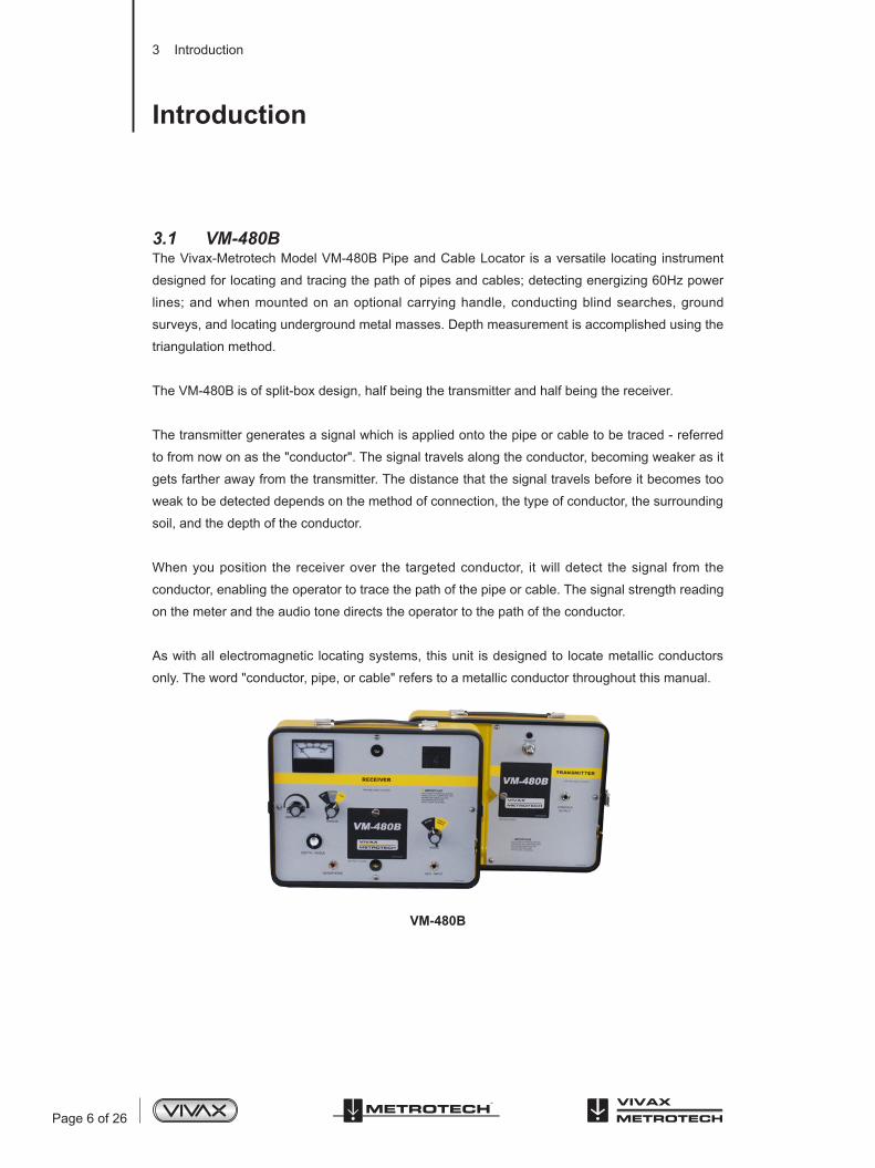
3.1 VM-480BThe Vivax-Metrotech Model VM-480B Pipe and Cable Locator is a versatile locating instrument
designed for locating and tracing the path of pipes and cables; detecting energizing 60Hz power
lines; and when mounted on an optional carrying handle, conducting blind searches, ground
surveys, and locating underground metal masses. Depth measurement is accomplished using the
triangulation method.
The VM-480B is of split-box design, half being the transmitter and half being the receiver.
The transmitter generates a signal which is applied onto the pipe or cable to be traced - referred
to from now on as the "conductor". The signal travels along the conductor, becoming weaker as it
gets farther away from the transmitter. The distance that the signal travels before it becomes too
weak to be detected depends on the method of connection, the type of conductor, the surrounding
soil, and the depth of the conductor.
When you position the receiver over the targeted conductor, it will detect the signal from the
conductor, enabling the operator to trace the path of the pipe or cable. The signal strength reading
on the meter and the audio tone directs the operator to the path of the conductor.
As with all electromagnetic locating systems, this unit is designed to locate metallic conductors
only. The word "conductor, pipe, or cable" refers to a metallic conductor throughout this manual.
VM-480B

Page 7 of 26
3 Introduction
3.2 Controls and Indicators of the Model VM-480B Transmitter
VM-480B Transmitter: Controls and Indicators
1
23
4
1
2
3
4
POWER INDICATOR LAMP
Indicates power is on. Blinks steadily if battery power is good, will slow down according
to power left in batteries. When it stops blinking, replace the batteries.
COND/AUX OUTPUT JACK
Insert either the direct connect cable or the 4820 Metroclamp cable into this jack. The
transmitter’s internal antenna is automatically disconnected when a plug is inserted into
this jack.
BATTERY ACCESS
PUSH/PULL POWER SWITCH
Pull this switch to turn the transmitter on. Power Indicator lamp will blink.

Page 8 of 26
1 2
3
4
5
6
7
89
10
1
2
3
4
5
6
7
8
9
10
FIELD STRENGTH METER
The meter indicates the strength of the signal being received by the receiver. The
reading will vary according to how close the receiver is to the conductor. The receiver
displays the highest reading when it is directly over the target conductor.
BATTERY TEST INDICATOR
When the receiver is turned ON, the needle should move into the BATT test area of the
meter. If it does not, the batteries need to be replaced.
CARRYING HANDLE THREADED BUSHINGS
Connection point for Carrying Handle screws.
SPEAKER
Emits audio tone which guides operator toward the targeted conductor.
MODE SWITCH
Two operating positions:
Active – Direct Connect, Inductive coupling and inductive
Passive – For tracing energizing 50/60Hz power lines
AUX INPUT Jack
Plug in second 4820 Metroclamp (when using two clamps) into this jack.
BATTERY ACCESS
HEADPHONE JACK
Plug in point for headphones.
DEPTH ANGLE BUBBLE
Position the bubble in the indicated area to estimate the depth.
RANGE KNOB
Changes the ratio of the signal amplification.
SENSITIVITY KNOB
Controls the signal gain. Set as low as possible to avoid receiving signal from conductors
other than your target conductor.
3.3 Controls and Indicators of the VM-480B Receiver
VM-480B Receiver: Controls and Indicators
3 Introduction

Page 9 of 26
To insure proper operation of the VM-480B Pipe and Cable Locator, use the checkout procedure
at the following times:
• Upon receiving the equipment
• Before each job, preferably before you leave for the site
• If problems arise during a locate
1. Turn the transmitter on by pulling the PUSH/PULL POWER SWITCH and place the transmitter
on the ground. If the batteries are working, the battery lamp will blink.
2. Turn the receiver ON (if the batteries are working, the meter will move to the BATT section of
the meter) and set to the Active/Norm Mode.
3. Set the SENSITIVITY knob to the “SET” line.
4. Hold the receiver in a position parallel to the transmitter. The meter needle should move all the
way to the right side of the meter, and the audio tone should be loud.
5. Move away from the transmitter, holding the receiver in the same parallel position. At 10-20ft
the signal level should start to drop - the meter needle will move to the left and the audio tone
will begin to fade.
6. Turn the receiver perpendicular to the transmitter - both the meter reading and the audio tone
should suddenly drop.
If either the receiver or the transmitter does not respond to the above tests, check the batteries.
Refer to Section 7, Maintenance for instructions.
4.1 To Check the 50/60Hz Power Mode1. Test the receiver only (the transmitter is not required for passive locating). Stand under an
indoor AC powered light future.
2. Set the range to “HIGH” and the sensitivity to the 12 o’clock position.
3. Hold the receiver in a vertical position and raise the receiver upward toward the light fixture. The
meter reading and audio tone should increase as the receiver gets closer to the light fixture.
If either the receiver or the transmitter does not respond to the above tests, check the batteries.
Refer to Section 7, Maintenance for instructions.
NOTEThe VM-480B receiver features a 30-minute automatic shut-off to prevent the receiver from being accidentally left on. A beep will sound to alert the operator that the receiver is about to shut off. Reactivate the receiver by turning the RANGE KNOB back to “OFF” and then to “NORM” or “HIGH”.
4 Checkout Procedure
Checkout Procedure
Page 10 of 26
5 Operation
Operation
Follow the checkout procedure described in Section 4 before operating the equipment.
To operate the VM-480B pipe and cable locator, use the transmitter to apply the signal to the
conductor, and use the VM-480B receiver to trace the signal coming off the conductor.
For a successful locate you must be sure that you have the best possible connection to the target
conductor and that the conductor is well grounded. If there is a break in the circuit path, very
little transmitter signal will reach the receiver. Look for disconnected leads, circuit breakers, open
switches, insulators, etc.
Power lines and telephone sheaths are assumed to be grounded. If you are tracing a conductor
with an exposed insulated joint, such as a gas pipe with a gas meter, use the jumper cable
to bypass the meter (insulator). Attach each end of the jumper cable to opposite sides of the
insulator.
To trace non-metallic pipe (sewer line) or duct send the signal through the conductor by inserting
a snake or fish tape into the pipe and connecting the Direct Connect Cable from the transmitter to
one end of it.
WARNINGNever make a direct connection to a live power cable. Use a voltmeter to check for active electrical power. Always make sure the power to a cable is turned off before you make a direct connection to it. (Live secondary power can be located safely using an Inductive clamp.)
5.1 To Start LocatingThere are three different methods of applying the signal to the conductor with the transmitter
- Direct Connection, Inductive Coupling and Inductive. A description of each method and use
instructions follow below.
In addition to three different methods of inducing the signal onto the conductor, there are two
methods - PEAK and NULL by which to locate your conductor.
The PEAK method is generally used to follow the path or direction of a line. It is the preferred
method for general locating because the sensitivity or gain can be kept to a minimum which
prevents bleed-off onto nearby lines.
Page 11 of 26
5 Operation
The NULL method is used for more accurate locating of the centerline of a conductor. You
would want to get an accurate locate of a conductor centerline before determining the depth of a
conductor.
PEAK and NULL procedures are described below.
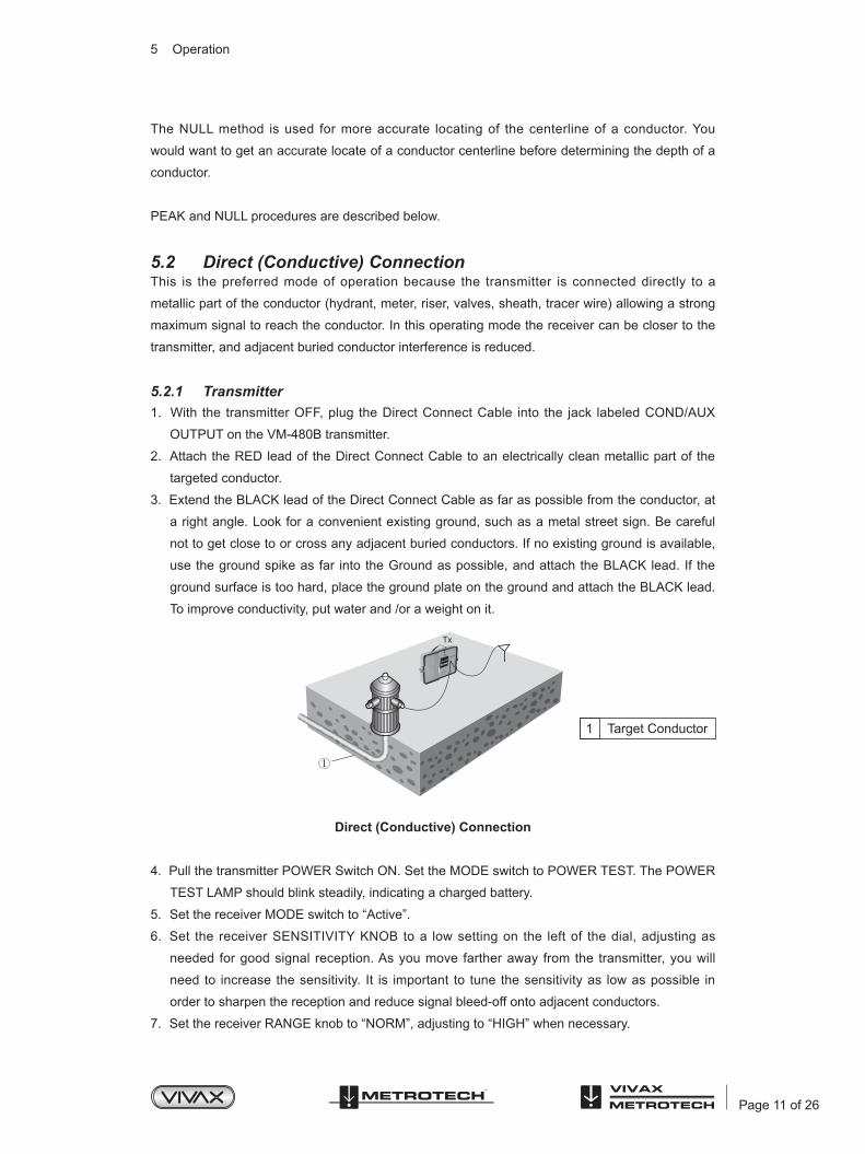
5.2 Direct (Conductive) ConnectionThis is the preferred mode of operation because the transmitter is connected directly to a
metallic part of the conductor (hydrant, meter, riser, valves, sheath, tracer wire) allowing a strong
maximum signal to reach the conductor. In this operating mode the receiver can be closer to the
transmitter, and adjacent buried conductor interference is reduced.
5.2.1 Transmitter1. With the transmitter OFF, plug the Direct Connect Cable into the jack labeled COND/AUX
OUTPUT on the VM-480B transmitter.
2. Attach the RED lead of the Direct Connect Cable to an electrically clean metallic part of the
targeted conductor.
3. Extend the BLACK lead of the Direct Connect Cable as far as possible from the conductor, at
a right angle. Look for a convenient existing ground, such as a metal street sign. Be careful
not to get close to or cross any adjacent buried conductors. If no existing ground is available,
use the ground spike as far into the Ground as possible, and attach the BLACK lead. If the
ground surface is too hard, place the ground plate on the ground and attach the BLACK lead.
To improve conductivity, put water and /or a weight on it.
Direct (Conductive) Connection
4. Pull the transmitter POWER Switch ON. Set the MODE switch to POWER TEST. The POWER
TEST LAMP should blink steadily, indicating a charged battery.
5. Set the receiver MODE switch to “Active”.
6. Set the receiver SENSITIVITY KNOB to a low setting on the left of the dial, adjusting as
needed for good signal reception. As you move farther away from the transmitter, you will
need to increase the sensitivity. It is important to tune the sensitivity as low as possible in
order to sharpen the reception and reduce signal bleed-off onto adjacent conductors.
7. Set the receiver RANGE knob to “NORM”, adjusting to “HIGH” when necessary.
Tx
1 Target Conductor
Page 12 of 26
8. When starting a locate, you need to “prelocate” the targeted conductor by using the broad
range PEAK method first to find the general location of the line. Then hone in on the exact
location of the conductor with the precision NULL method.
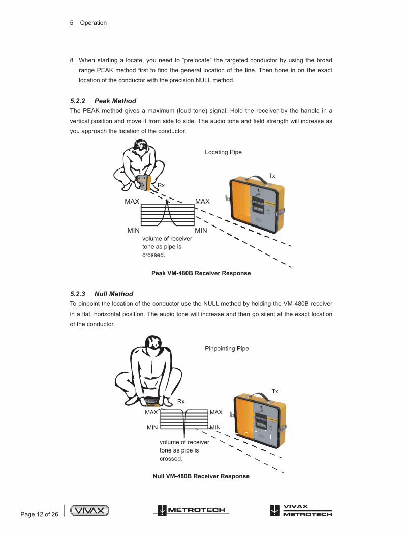
5.2.2 Peak MethodThe PEAK method gives a maximum (loud tone) signal. Hold the receiver by the handle in a
vertical position and move it from side to side. The audio tone and field strength will increase as
you approach the location of the conductor.
Peak VM-480B Receiver Response
5.2.3 Null MethodTo pinpoint the location of the conductor use the NULL method by holding the VM-480B receiver
in a flat, horizontal position. The audio tone will increase and then go silent at the exact location
of the conductor.
Null VM-480B Receiver Response
MAX
MIN
MAX
MIN
RxTx
volume of receivertone as pipe iscrossed.
Locating Pipe
MAX
Rx
Tx
MIN
MAX
MIN
volume of receivertone as pipe iscrossed.
Pinpointing Pipe
5 Operation

Page 13 of 26
WARNINGDo not hold the receiver at an angle – Incorrect information will result!
1. To determine the direction of the conductor, stop and vertically rotate the receiver to the left
and right. The highest signal strength reading indicates the direction of the conductor.
Continue to trace the conductor in the direction indicated by the indicators on the receiver. If
the signal strength drops abruptly, the conductor may have changed direction or stopped.
2. When you have pinpointed the conductor's location, mark it as required. See Section 5.6 for
APWA color markings.
3. When you have finished the locating, turn the transmitter and receiver off and disconnect the
accessories.
5.3 Inductive Coupling with the 4820 MetroclampUse this method if Direct Connection is not possible, but you can position a Metroclamp around
the conductor you want to trace. The Inductive Coupling method uses the 4820 Metroclamp to
induce a signal onto the conductor when direct metallic contact is not possible. The clamp is
placed around the target conductor. The transmitter then induces a signal through the clamp.
When using the Metroclamp the conductor must be well grounded, i.e. with sheaths and neutrals.
When tracing lines that have insulators, the insulators should be bypassed, using the supplied
jumper cable.
1. With the transmitter OFF, plug the 4820 Metroclamp cable into the COND/AUX jack on the
VM-480B transmitter.
2. Place the Metroclamp around the conductor, below the electrical ground. Make sure that the
clamp jaws are completely closed.
Inductive Coupling with the Metroclamp3. Continue your locating by following steps 4 through 11, Section 5.2 Direct Connection.
5.4 Inductive (Indirect Method)If you cannot make a direct connection onto the conductor, or use the Metroclamp, use the
antenna that is mounted on the transmitter case to induce signal onto the conductor.
1 Insulator
2 Pipe
Couplers must be placed below
the electrical ground.
5 Operation

Page 14 of 26
This is the least preferred method of inducing signal onto a conductor because the signal is
broadcast through the soil and air and can be picked up by other conductors in the area. In this
mode the signal radiates from the antenna mounted on the transmitter case and couples to the
conductor by electromagnetic induction.
If no direct connect cable or Metroclamp is attached to the DIRECT/4820 CLAMP jack, the
transmitter automatically broadcasts the signal through the antenna mounted on the transmitter
case.
No ground connection is needed when a signal is induced onto the target conductor.
WARNINGDo not operate the transmitter in the Inductive Mode while it is resting on or near a metal surface or large metal object. Incorrect test readings and damage to the transmitter may result.
1. Position the transmitter over the buried conductor making sure that the transmitter is parallel
or in line directly over the targeted conductor.
2. When using the Inductive method, the receiver must be 35-50 ft. away from the transmitter
depending on how high the sensitivity is set. The higher the sensitivity, the farther from the
transmitter the receiver must be to avoid picking up the transmitter signal traveling through the air.
3. Continue your locate by following steps 4 through 11, Section 5.2 Direct Connection.
5.5 VM-480B 50/60Hz Power Line LocatingWhen locating a power line the VM-480B transmitter is not required as you are locating the power
line by tracking the path of the 50/60 current coming off the line (the line must be loaded).
This method gives a maximum (loud tone) signal. The VM-480B receiver is held in a vertical position at right angles to the line for maximum signal. (Note the logical path of the line from the source).
You will notice a different audio tone when using the 50/60Hz mode, this is normal.
50/60 Power Line Locating Operation:1. Move the VM-480B receiver a few feet away from where you want to start searching.
2. Turn the receiver MODE Switch to “Passive 50/60Hz”.
3. Hold the receiver in a vertical position. Then adjust the SENSITIVITY knob to bring the needle
within the “SET” zone. If the meter does not adjust to “SET”, turn the SENSITIVITY knob
all the way to the right (clockwise) and/or move closer to the conductor. If you still cannot
adjust to the “SET” position, switch the RANGE knob to “HIGH”:, and then attempt to adjust
the SENSITIVITY to “SET”. (If no current is present you will be unable to adjust to “SET”).
4. Hold the receiver in an upright, vertical position with the face of the receiver facing you, and at
right angles to the targeted conductor.
5 Operation

Page 15 of 26
5. Move the receiver from side to side over the targeted conductor location until you obtain the
maximum PEAK response. For better signal reception, hold the receiver close to the ground.
As you move closer to the targeted conductor, the speaker tone will gradually get louder. The
loudest tone will indicate you are over the conductor in the PEAK mode.
6. If the needle is at or close to the end of the meter scale, adjust the SENSITIVITY knob to bring
the needle back to the middle of the meter. (Decreasing the SENSITIVITY will give a sharper
receiver response as you move closer to the target conductor.) Then move to a new position
and note the meter response. The meter reading will increase if the signal gets stronger (closer
to the conductor), or decrease if the signal gets weaker (further from the conductor).
7. Keep adjusting the SENSITIVITY knob and the position of the receiver until you find a place
that gives a maximum reading. (This will occur when the receiver forms an angle of 90
degrees with the target conductor.)
5.6 Estimating the Depth of a ConductorFollow this procedure to estimate the depth of a buried conductor:
1. Using the NULL method, find the exact location of the conductor. At a minimum distance of 35
feet from the transmitter (to prevent air coupling between the transmitter and receiver), locate
and mark the conductor.
2. Then, still in the same mode of operation (NULL), tilt the receiver to 45 degrees (aligning the
bubble), and move off to the side of the conductor. See below graphic.
Estimating the Depth of a Conductor
3. When you "locate" the conductor a second time, with the receiver at a 45 degree angle, mark
the spot on the ground. The distance between this second spot and the true location of the
conductor (A), less the distance between the center of the receiver and the ground (B), is
equal to the depth of the conductor (C). See graphic above.
4. Measurement accuracy is affected by the ratio of the conductor diameter compared to how
deep the conductor is buried. (The larger the pipe the less accurate the depth measurement.)
Depth measurements are also affected by soil conditions, overhead lines, and adjacent
conductors.
Rx45°
B A
C = A·BPIPE
C
C (Depth of Conductor) = A-B
Second “Location”
Pipe Location
5 Operation

Page 16 of 26
5.7 Using the Carrying Handle for Blind Searching, Ground Surveys, and Metal Mass Location
To conduct a blind search, a ground survey, or to locate an underground metal mass, the VM-
480B transmitter and receiver must be mounted on a carrying handle (Part# 200766). The handle
positions the receiver and the transmitter in correct relation to each other.
5.7.1 Mounting the VM-480B Transmitter and Receiver to the Carrying Handle1. Assemble the Carrying Handle as shown below. Do not insert the end pieces beyond the stop
pins. Secure the screws on the center section.
Carrying Handle Assembly
2. Mount the VM-480B transmitter onto the Carrying Handle by placing the single screw-end of
the handle into the transmitter and securing it to the transmitter with the handle screw. See
below graphic, Step 1.
3. Place the mounted transmitter on the ground as shown and attach the VM-480B receiver to
the handle, screwing the two handle screws into the two threaded bushings on the receiver.
The receiver should be perpendicular to the transmitter as shown below, Step 2.
Mounting the Transmitter and Receiver onto the Carrying Handle
4. Pull the transmitter POWER switch on.
5. Set the receiver RANGE switch to "Norm" (the Receiver will turn on).
6. Set the receiver SENSITIVITY Switch to "11 o'clock position."
1 Stop Pin
Step 1 Step 2
1 Receiver
2 Transmitter
5 Operation
Page 17 of 26
7. Set the receiver MODE Switch to "Active".
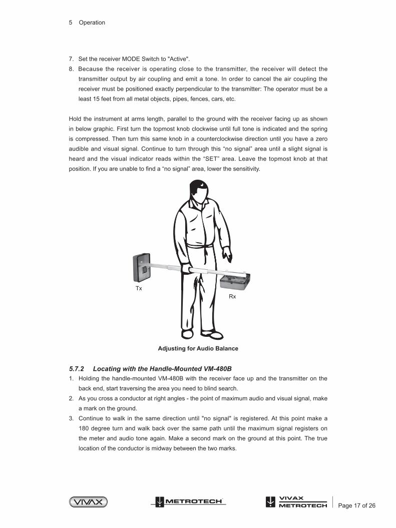
8. Because the receiver is operating close to the transmitter, the receiver will detect the
transmitter output by air coupling and emit a tone. In order to cancel the air coupling the
receiver must be positioned exactly perpendicular to the transmitter: The operator must be a
least 15 feet from all metal objects, pipes, fences, cars, etc.
Hold the instrument at arms length, parallel to the ground with the receiver facing up as shown
in below graphic. First turn the topmost knob clockwise until full tone is indicated and the spring
is compressed. Then turn this same knob in a counterclockwise direction until you have a zero
audible and visual signal. Continue to turn through this “no signal” area until a slight signal is
heard and the visual indicator reads within the “SET” area. Leave the topmost knob at that
position. If you are unable to find a “no signal” area, lower the sensitivity.
Adjusting for Audio Balance
5.7.2 Locating with the Handle-Mounted VM-480B1. Holding the handle-mounted VM-480B with the receiver face up and the transmitter on the
back end, start traversing the area you need to blind search.
2. As you cross a conductor at right angles - the point of maximum audio and visual signal, make
a mark on the ground.
3. Continue to walk in the same direction until "no signal" is registered. At this point make a
180 degree turn and walk back over the same path until the maximum signal registers on
the meter and audio tone again. Make a second mark on the ground at this point. The true
location of the conductor is midway between the two marks.
RxTxTx
5 Operation
Page 18 of 26
5.7.3 Blind Search, Metal Mass Location, Ground Survey with the Carrying Handle
A "blind search" is a search for the location of a conductor with an unknown source or ending.
The VM-480B must be operated in the Inductive Mode using a systematic grid approach. Looking
for a "metal mass", such as a manhole cover or steel drum is the same as a "blind search" with
the exception that the search paths need to be closer together so as not to miss the metal object.
A "ground survey" is a process by which an operator can locate all the underground conductors
within a particular area.
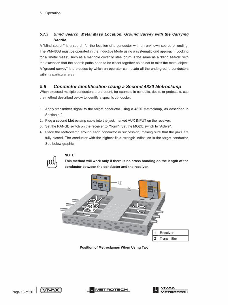
5.8 ConductorIdentificationUsingaSecond4820MetroclampWhen exposed multiple conductors are present, for example in conduits, ducts, or pedestals, use
the method described below to identify a specific conductor.
1. Apply transmitter signal to the target conductor using a 4820 Metroclamp, as described in
Section 4.2.
2. Plug a second Metroclamp cable into the jack marked AUX INPUT on the receiver.
3. Set the RANGE switch on the receiver to "Norm". Set the MODE switch to "Active".
4. Place the Metroclamp around each conductor in succession, making sure that the jaws are
fully closed. The conductor with the highest field strength indication is the target conductor.
See below graphic.
NOTEThis method will work only if there is no cross bonding on the length of the conductor between the conductor and the receiver.
Position of Metroclamps When Using Two
1 Receiver
2 Transmitter
5 Operation

Page 19 of 26
5.9 Marking the ConductorThe following color markings have been established by the American Public Works Association
(APWA):
NOTEIf you have any questions regarding marking requirements or procedures, please call your local One Call Center
ConductorElectric power lines, cables, or conduits
Communication lines, cables, conduits, CATV
Gas, oil, petroleum, or other gaseous materials
Storm and sanitary sewers, drain lines
Water, irrigation, or slurry lines
ColorRed
Orange
Yellow
Green
Blue
5 Operation

Page 20 of 26
6 Tracing Factors and Helpful Information
Tracing Factors and Helpful Information
Many variables affect the process of locating a pipe or cable. The following information gives
guidelines for various problem situations.
6.1 Soil ConditionsGenerally, the effect of soil types on line tracing is as follows:
Soil Type Effect on Line Tracing
Moist, compact Ideal
Dry, sandy, or rocky Little or no moisture content creates a poor tracing environment
Alkaline, high iron content Poor tracing environment
6.2 Field Strength of the SignalWhen the signal is applied to the conductor using any of the three "Active" methods covered
in Section 5.2 – 5.5, an electromagnetic field is created around the conductor. The receiver
measures the strength of this field, displaying it on the field strength meter.
The field strength decreases as you move away from the target conductor and as you move
farther away from the transmitter (in the "Active" mode). For optimum tracing accuracy, the field
strength should read at least 5 on the meter at maximum gain.
6.3 Verifying Versus TracingVerifying means to confirm that a conductor if present, and tracing means to map out its route
along the ground. Besides its use for locating a cable, the VM-480B’s 50/60Hz power line locating
mode is also helpful for determining the presence of energizing power lines and other conductors.
The active range using the transmitter generally produces the best accuracy when tracing.
6.4 Adjacent ConductorsWhen the meter reading drops off more on one side of the conductor than it does on the other,
the receiver may be picking up interference from an adjacent or parallel conductor. Adjust the
sensitivity to compare the signal strength of the conductors. In most cases, the conductor with
the stronger signal is the target conductor. If you are using the Active Mode, confirm the exact
location of the adjacent conductors. Place your ground lead so that it does not cross over any
adjacent conductors, is perpendicular to, but as far away from your target conductor as possible.
Note evidence of other underground utilities in the area, such as transformers, pedestals,
hydrants, meters, etc. which indicate the presence of other underground conductors.

Page 21 of 26
100ftTrace Path
WATER MAIN
5ft
6 Tracing Factors and Helpful Information
6.5 Deep ConductorSignals picked up by the receiver from deep buried pipes are weaker and not as directionally
distinct as those from pipes closer to the surface. In addition, the meter reading will only change
by small increments in relation to moving the receiver antenna.
Using the Inductive (Indirect) Method of coupling signal to the conductor may be difficult if
the target conductor is buried four feet or more. For best results, use the Direct (Conductive)
Connection method of coupling signal to the targeted conductor.
6.6 Tracing Long RunsSignals picked up by the receiver get weaker as you move further and further away from the
transmitter coupling point, especially on long pipe runs. To get a stronger signal, move the
transmitter coupling point closer to the receiver. If forced to use the Inductive Indirect mode, your
tracing job will be easier if an assistant follows behind with the transmitter as you trace with the
receiver.
6.7 Locating a Service Lateral - Active Range/Inductive ModeAfter you have traced the main, you may want to go back and locate the service laterals off the
main. Service lateral traces are easiest to conduct in the Inductive Mode. Two operators are
required for this procedure - Operator 1 remains stationary holding the receiver as if to trace
over and parallel to the main. Operator 2, carrying the transmitter, holding it perpendicular to the
main line, and maintaining a minimum of 100 ft. between himself and the receiver, walks parallel
but 5 feet from the main on the side he expects to find the service laterals as shown below. The
meter reading on the receiver will increase as Operator 2 crosses over the service lateral with
the transmitter. Each time the meter reading increases Operator 1 signals Operator 2 and he/she
marks the lateral locations on the ground.
Locating Service Laterals

Page 22 of 26
6.8 Locating a Bend or Dead EndWhile tracing a line, you may find that the meter reading drops off suddenly, and that there is no
distinct reading when the receiver antenna is moved left or right. Stand in place and continue
sweeping the antenna from side to side but at the same time slowly pivot your body.
If you find a pivot angle at which the meter reading picks up again, it means you've located a
bend and can resume tracing in the new direction.
If you pivot all the way around (360 degrees), without getting any noticeable meter reading, it
means you've reached a dead end.
6.9 Valves, Manhole Covers, Tees and RisersIf the meter reading suddenly increases and then falls back while tracing a pipe you have
probably passed over a buried valve, manhole cover, tee, or riser.
6.10 Common Bonded ConductorsTelephone, power, and CATV sometimes use a common ground bond. If other conductors are
connected to your target conductor, putting a signal on the target can cause all the conductors to
carry the same signal, making it difficult to identify the target conductor.
To verify that you are tracing the targeted conductor, note the field strength at a known location
of the conductor. As you trace, any change in field strength should be gradual. If either reading
changes abruptly you are probably no longer over your targeted conductor.
6.11 Congested AreasIf you suspect that coupling from adjacent conductors is causing interference in the signal picked
up by the receiver try increasing the strength of the signal received from the transmitter and
decreasing the strength of signal from the interfering conductors by:
1. Changing to a different transmitter coupling point or coupling mode.
2. Improving the grounding connection or moving the grounding point.
3. Determine the location of the adjacent conductors. Then check to be sure that neither the
direct connect cable or the ground cable cross over any of the adjacent conductors. Re-
position them if necessary.
4. If you are using the Inductive (Indirect) mode, you may be able to decrease the amount of
interfering signal by changing the orientation of the transmitter to the targeted conductor.
Determine the location of the interfering conductor.
6.12 Pipes with Insulated JunctionsThe high radio frequency signal of the VM-480B Pipe and Cable Locator will jump pipe insulators,
however, the signal will proportionately decrease each time it crosses an insulator. When
possible, such as when tracing a pipe with a meter, bypass the meter (insulator) by using a
jumper cable. Attach each end of the jumper cable on opposite sides of the insulator.
6 Tracing Factors and Helpful Information
Page 23 of 26
6.13 Metroclamp Ground RequirementsIf you are using the Metroclamp around a cable, both ends of the target conductor must be
grounded to insure sufficient field strength. Power lines and telephone sheaths are assumed to
be grounded.
6.14 Grounding SafetyIf you use the direct connect method, be sure that there is no power flowing through the target
conductor. If you use the Metroclamp on energized lines, follow established safety procedures.
6.15 Distribution SystemsTo locate short gas services on a gas distribution system, you should temporarily ground the end
of the service. This can be accomplished by temporarily connecting a jumper cable to a ground
spike at the end of a service, where the pipe or tracer wire comes out of the earth. Be sure to
remove the ground connection after completing the locating so as not to defeat the cathodic
protection system.
6 Tracing Factors and Helpful Information
Page 24 of 26
7 Maintenance
Maintenance
The only routine maintenance required for the Model VM-480B equipment and accessories is
to test and replace, if necessary, the batteries in the transmitter and the receiver. Both possess
battery test features, making it easy to check the condition of the batteries at any time.
We recommend checking the transmitter and receiver batteries before each use, preferably
before leaving for the job site.
7.1 Checking and Replacing the VM-480B Transmitter and Receiver Batteries
Check and replace the transmitter and receiver batteries as follows:
1. Have ready 6 C Cell batteries.
2. To test the transmitter batteries, pull the power switch on. The LED will blink steadily if the
batteries are in good condition. It will begin to slow down as the batteries lose power. If it does
not blink at all, the batteries need to be replaced.
3. To test the receiver batteries, turn the Range Knob to "NORM". The needle on the field
strength indicator should move into the BATT test area. If it does not, the batteries need to be
replaced.
4. To replace batteries in either the transmitter or the receiver, open the BATTERY ACCESS door
on the front of the unit. Extract the battery holder and replace batteries, positioning according
to the indications shown inside the battery holder.
5. Close the battery access panel, ensuring that there are no wires caught between the receiver
body and the access panel. Make sure the latch is securely fastened.
7.2 Basic Preventive MaintenanceThe Model VM-480B is designed for rugged outdoor use, but rough handling should be avoided.
Keep the equipment dry, clean, and free of grit.

Page 25 of 26
A locate where a transmitter is used to apply a signal to a buried pipe
or cable, the position of which is then located by a receiver tuned to
the same frequency.
A signal applied by the locator transmitter to a buried line. Typical this
is a very precise frequency.
The reduction of an electromagnetic signal from a pipe or cable.
An accessory used to apply the transmitter signal to an insulated
line, removing the need to connect the transmitter signal directly to a
conductor or cable sheath.
The act of signals transferring to lines to which they were not originally
applied. Coupling can be “direct” where the target line has an electrical
connection to another line, or “induced” where the signal radiates from
the target line to another line or lines.
The information visually available on the dot matrix display.
A generic term for any buried pipe or cable.
A minimum response to a buried line
A locate where the receiver searches for a wide range of signals that
radiate from buried pipes or cables. These signals come from a variety
of sources in the environment and couple to the buried (& overhead)
lines. Typical examples 50/60Hz and LF/VLF radio.
A wide range of signals that radiate from buried pipes or cables. These
signals come from a variety of sources in the environment and couple
to the buried (& overhead) lines. Typical examples 50/60Hz and LF/
VLF radio.
A maximum response to a buried line
Using a receiver to identify the exact position of a buried line.
Active Locate
Active Signal
Attenuation
Clamp (or Coupler)
Coupling
Display
Line
Null
Passive Locate
Passive signals
Peak
Pinpoint
8 Glossary
Glossary
Page 26 of 26
The indication that the receiver gives which is caused by the signals it
is receiving. This can be visual, audio or both. Typically it is displayed
on the locators dot matrix display and audibly from a loudspeaker in
the receiver housing.
This describes the act of looking for a buried line within a given area.
A small transmitting coil which may be built into a product such as a
sewer camera or packaged as a small self contained battery powered
transmitter. A receiver tuned to the same frequency can locate the
position of the Sonde and hence whatever it is attached to or in.
Frequently used for locating sewer cameras, and the non metallic
pipes.
The buried pipe or cable to be located.
Using a locator to following the path of a buried line.
Response
Search (sweep)
Sonde
Target Line
Trace
Illustrations used in the preparation of this manual will inevitably show some resemblance to
similar illustrations from other Manufacturers-some manufacturers have given permission for the
use of their graphics (Vivax-Metrotech & Seba) is given credit for these uses. This statement is
intended to attribute such credit.
Disclaimer: Product and accessory specification and availability information is subject to change
without prior notice.
8 Glossary

Notes:
Vivax-Metrotech Corporation,3251 Olcott St.,Santa Clara CA 95054, USA
Website: www.vivax-metrotech.com