VLVES N CTATORS - Автоматика CONTROLLIcontrolli.ru/new_catalog.pdf · useR-fRIendlY...
64
VALVES AND ACTUATORS 1
Transcript of VLVES N CTATORS - Автоматика CONTROLLIcontrolli.ru/new_catalog.pdf · useR-fRIendlY...

VALVES AND ACTUATORS
1


CONTROLLI was established in Genoa in 1936 and was the first Italian company to manufac-ture a complete range of controllers, actuators and control valves for heating and air-condi-tioning systems.
Since 1950 the product range was improved by widening the range of control equipments and systems for industrial application.
In the 80s CONTROLLI consolidates its position as the most important Italian manufacturer, with special regard to climate controls, thanks to the development of analogue and digital electronic devices.
In the 90s CONTROLLI gains a position also in the Building Automation market.From 1996 to July 2005 CONTROLLI has been part of the Invensys multinational group. From 2005 to August 2011 CONTROLLI has been part of Schneider Electric S.A.
CONTROLLI core business consists of products and systems for the control and supervision of HVAC plants and industrial processes.
CONTROLLI products are the result of mechani-cal - electric - electronic technology integration, supported by a 75-year experience in HVAC
applications.
An industrial complex of 6,000 m2 in Sant’Olcese (Genoa) is CONTROLLI head office. Production is highly automated with robotic devices for the assembly and calibration of mechanical and electronic spare parts and finished products.It is worth mentioning the robotic plant for pro-cessing, mounting and testing of valve bodies and the robotized workcell for assembly, test-ing and certification of fan-coil valve actuators. CONTROLLI has adopted the SIX SIGMA proce-dures, further elevating the quality standard of its products. CONTROLLI operates under ISO9001-2000 Quality Certificate System and ISO14000. All CONTROLLI valves are PED (Pressure Equip-ment Directive) compliant.Products are tested 100%.
ACTIVITy
RESEARCH &DEVELOPMENT
MANufACTuRINGSITE
*The port of Genoa as seen from uphill

SALES ORGANIZATIONSales & Marketing Dept. is in Sant’Olcese (Genoa).Italian sales network consist of Sales-Offices in Milan, Genoa and Rome, 45 representatives and 75 authorised dealers throughout the Italian territory.Abroad CONTROLLI operates through a widespread net-work of distributors and agents in Europe, Africa, Mid-dle East, Far East, North and South America. By getting in touch with the nearest CONTROLLI sales point, the customers will find solution to any technical and com-mercial issue.
TECHNICAL SuPPORTOur offices will provide a continuous technical assis-tance and support for systems and devices, application information, quotations and wiring diagrams.Moreover, CONTROLLI holds periodically training cours-es for different levels of technical expertise and class of customers.
WHERE TOfIND uSControlli S.p.a.
Via Carlo Levi, 5216010 S. OlceseGenova - Italy
Controlli is located 10 Km north of Genova.
By Car: take the A7 highway (Genova-Milano) and exit at Genova Bolzaneto.
GPS: 44.4862, 8.9223
By Plane: distance from Genova Airport is 15Km
MILANO
GENOVAFCONTROLLI
CH
A
SLO
HR
ITALY

LITERATuREControlli provides a series of resources to make it as easy as possible for you to identify the products you need.
Specify manufacturing and technical characteristics of prod-ucts and their application, installation, wiring connections and start-up instructions.
Gives a brief description of Controlli product range according to different applications.
Provide the information for the correct use of the equipment and for its maintenance.
Advertise single Controlli products or control systems.
Illustrate the most common applications, indicating the equipment of control system, basic system and wiring dia-gram.
Lists the prices and sales conditions.
Our product range catalogue is also available on CD-ROM
Available for technical information, selection, application and quotations of equipment and complete control systems.
Consisting of our technical staff and authorised assistants for technical support, commissioning, repairs and maintenance.
Courses are held periodically for both technical and commer-cial staff on equipment and control systems. Moreover, there are courses aimed at the users of digital supervision systems.
Check our total portfolio by visiting www.controlli.eu, which gives direct access to the latest version of all our data sheets.
DATA SHEETS
PRODuCT SELECTION GuIDE
uSERS’ INSTRuCTIONS
BROCHuRES
APPLICATION DIAGRAMS
PRICE LIST
CD
APPLICATION ENGINEERING OffICE
SALES SERVICE
TECHNICAL TRAINING COuRSES
WEB SITE
SERVICES
WEBuP.CONTROLLI.Euour customers have free access to our WEBUP online service, where they can check the updated situation for any order, shipment, as well as download documents, invoices.

COREBuSINESS
SuPERVISORy SySTEMTo make matters easy, we propose pre-programmed GT (graphic terminals) touch-
screens, with web Server capabilities for remote monitoring through Internet Explorer. GT touch-screens are supplied ready for most of our controllers (W500,
AXCU22/WMB, DG8000, OmniaPro, Liberty). One GT is suitable to approx. 40 con-trollers at one time.
CONTROLLERSTo start with, we will mention our thermostats for heating
and cooling, our fan-coil units controllers, room controllers, ddc controllers with parameter-setting as well as program-mable controllers. Not to forget our KX climatic controllers
with outside temperature compensation. Controllers are offered either as stand-alone or with ModBus connectivity.
Our range includes sensors, transmitters and switches for temperature, humidity, pressure, differential pressure, air
quality, etc.
VALVES & ACTuATORS
We are proud to offer one of the largest range of valves and actuators in the HVAC market. Valves range from 15mm to 200mm for fluids with temperature from -30°C to +350°C, max. pressure 12bar (steam) or 30bar (water). Linear actuators start at 90N and go up to 3000N. Rotary actua-tors for butterfly valves and shoes valves and for direct mounting on air dampers up to 2sqm.
MISCELLANEA PRODuCTSLast but not least, we are continuously improving our range for heat metering systems, variable speed drives, Dynamic Pressure Independent Control Valves, solu-tions for underfloor systems and more.
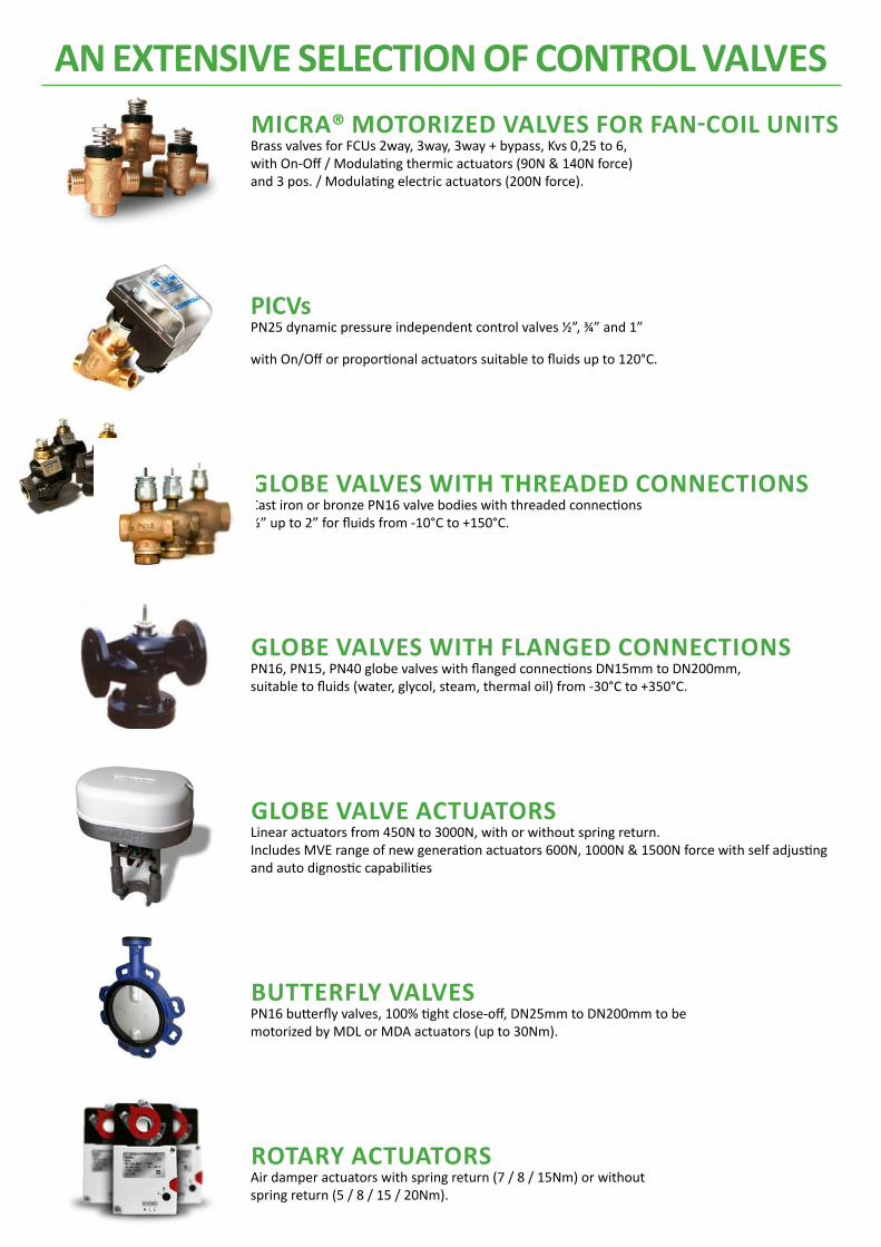
MICRA® MotoRIzed vAlves foR fAn-CoIl unItsBrass valves for FCUs 2way, 3way, 3way + bypass, Kvs 0,25 to 6,with On-Off / Modulating thermic actuators (90N & 140N force)and 3 pos. / Modulating electric actuators (200N force).
PICVsPN25 dynamic pressure independent control valves ½”, ¾” and 1”
with On/Off or proportional actuators suitable to fluids up to 120°C.
GLOBE VALVES WITH THREADED CONNECTIONSCast iron or bronze PN16 valve bodies with threaded connections ½” up to 2” for fluids from -10°C to +150°C.
GLOBE VALVES WITH fLANGED CONNECTIONSPN16, PN15, PN40 globe valves with flanged connections DN15mm to DN200mm, suitable to fluids (water, glycol, steam, thermal oil) from -30°C to +350°C.
GLOBE VALVE ACTuATORS Linear actuators from 450N to 3000N, with or without spring return.Includes MVE range of new generation actuators 600N, 1000N & 1500N force with self adjusting and auto dignostic capabilities
BuTTERfLy VALVESPN16 butterfly valves, 100% tight close-off, DN25mm to DN200mm to be motorized by MDL or MDA actuators (up to 30Nm).
ROTARy ACTuATORSAir damper actuators with spring return (7 / 8 / 15Nm) or withoutspring return (5 / 8 / 15 / 20Nm).
AN EXTENSIVE SELECTION Of CONTROL VALVES

useR-fRIendlY solutIons foR HvACfAN-COIL uNITS CONTROLLERSModels available with On/Off, floating or Proportional control with manual/automatic fan speed selec-tion. Some models (e.g. AXCU22/WMB) offer electric heater, automatic S/W change-over, window contact and ModBus connectivity.
PARAMETER-SETTING CONTROLLERSOMNIA® is the name of our range of digital controllers with 9 Inputs/Outputs for Temperature, Humid-ity and Pressure control. With P+I action, 4 control loops, 24Vac or 230Vac power supply, outside tem-perature compensation, low / high temperature/humidity limits, enthalpy control, free cooling. Models with RS485 provide Modbus connectivity, Real Time Clock, daily & weekly programs. All air handling units, including those with variable speed fan, are easily controlled by OMNIA controllers.
LIBERTY controllers are slightly bigger than Omnia controllers, with 19 I/Os and also include additional I/O modules. Display can be in-built or remote.All these ddc controllers are parameter-setting. No configuration tool is needed.
CONTROLS fOR INDuSTRIAL THERMAL PROCESSESDigital controllers with PID action (Proportional, Integrative, Derivative), with relay and analogue out-puts, display with set-point and actual values, Pt100 temperature sensor, suitable to applications with hot water service, plate heat exchangers, industrial thermal processes and whenever high accuracy control is required.
PROGRAMMABLE CONTROLLERSOMNIA Pro programmable controllers have 6 digital + 5 analogue Inputs and 5 digital + 3 analogue Out-puts, 2 triacs, I/O expansion modules, in-built or remote display, ModBus connectivity RS485 and RTC (option), Temperature & Humidity room sensor with display.
Applications include: AHUs with heating/cooling/humidity control, frost protection, compensation, optimization, free cooling, electric heater, heat pump. Central heating, hot water service, boliers and chillers sequencing and more. Models with with RS485 can be remotely monitored by GT Touch Screens. Maximum number of controllers monitored by one GT touch screen: from 10 to 40 controllers, depend-ing on the architecture.
TOuCH SCREEN THERMOSTATSAXT are user-friendly touch-screens for heating, cooling and many applications with 2-pipe/4-pipe FCUs, including electric heater, manual or automatic S/W change-over, remote control.
ROOM CONTROLLERSNot only FCU control! These DG8000 controllers perform room control management e.g. badge con-tact, room power input, window contact, occupancy control, alarms. Display panel frame can easily customised. Thanks to ModBus connectivity, these controllers are easily monitored through our GT touch-screens, thus representing an ideal solutions for hotels, hospitals, offices.

this page intentionally left blank

VALVES AND ACTUATORS
11
Micra - fan Coil Motorised ValvesActuators series MVX - Electrothermal actuator for normally closed V.X valves - Stroke end indi-cator - 2 m bipolar/tripolar cable - Protection IP44.
MoDElStartinG
tiME s.SUPPlY
VacForCE n aCtion
MVX21R 60 110-230 90 on-off
MVX41R 60 24 90 on-off, PWM
MVX57 60 24 90 proportional 0-10 Vdc
1) These models are also available with 40-mm port-to-port distance, instead of 35 mm. When ordering this version, add “4” at the end of the model code; e.g. VTX12P4.
Series V.X. - PN16 brass valve bodies - Tight close-off both on direct and angle way - NBR plug - Fluid: water and water+glycol 30% max. - Temperature 5 to 95 °C - Stroke 2.5 mm - Threaded connections for conic and flat tight - Motorised by MVX-MVR.
MoDEl
KvsCloSE-oFF
baraCtion tYPE DirECt WaY
tHrEaDED ConnECtionS tiGHtDirECt WaY
anGlE WaY
VSX09P 0.25 - 2.5
2-way n.c.
G 1/2” M flat
VSX10P 0.4 - 2.5 G 1/2” M flat
VSX11P 0.6 - 2.5 G 1/2” M flat
VSX12P 1 - 2.5 G 1/2” M flat
VSX13 1.6 - 2.5 G 1/2” M conic
VSX13P 1.6 - 2.5 G 1/2” M flat
VSX21 2.5 - 1.5 G 3/4” M conic
VSX21P 2.5 - 1.5 G 3/4” M flat
VMX09P 0.5 0.25 2.5
3-way
G 1/2” M flat
VMX10P 0.4 0.4 2.5 G 1/2” M flat
VMX11P 0.6 0.6 2.5 G 1/2” M flat
VMX12P 1 0.8 2.5 G 1/2” M flat
VMX13 1.6 1 2.5 G 1/2” M conic
VMX13P 1.6 1 2.5 G 1/2” M flat
VMX21 2.5 1.6 1.5 G 3/4” M conic
VMX21P 2.5 1.6 1.5 G 3/4” M flat
VTX09P1) 0.25 0.25 2.5
3-way 4-port
G 1/2” M flat
VTX10P1) 0.4 0.4 2.5 G 1/2” M flat
VTX11P1) 0.6 0.6 2.5 G 1/2” M flat
VTX12P1) 1 0.8 2.5 G 1/2” M flat
VTX13 1.6 1 2.5 G 1/2” M conic
VTX13P1) 1.6 1 2.5 G 1/2” M flat
VTX21 2.5 1.6 1.5 G 3/4” M conic
VTX21P 2.5 1.6 1.5 G 3/4” M flat
AccessoriesDESCriPtion
VXC - Manual control for V.X and V.XT series valves
Thermal insulation
Fittings
Customised valve mounting kit
1) These models are also available with auxiliary microswitch. When ordering this version, add the letter “M” at the end of the model code, e.g. MVR230M.
MVR series Electrothermal actuator for V.X valves with reverse action - 0.65 m cable - IP44 protection.
MoDElStartinG
tiME s.SUPPlY Vac ForCE n aCtion
MVR230V1) 60 110-230 90 on-off - normally open for Micra valve
MVR24V1) 60 24 90 on-off - normally open for Micra valve
90 n
90 n
Micra®
12
VALVES AND ACTuATORS
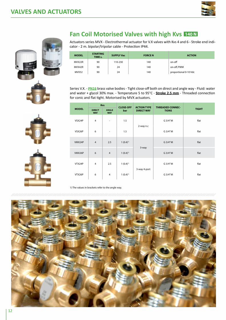
1) The values in brackets refer to the angle way.
Series V.X. - PN16 brass valve bodies - Tight close-off both on direct and angle way - Fluid: water and water + glycol 30% max. - Temperature 5 to 95°C - Stroke 2.5 mm - Threaded connection for conic and flat tight. Motorised by MVX actuators.
MoDEl
KvsCloSE-oFF
baraCtion tYPE DirECt WaY
tHrEaDED ConnEC-tionS
tiGHtDirECt WaY
anGlE WaY
VSX24P 4 - 1.5
2-way n.c
G 3/4” M flat
VSX26P 6 - 1.5 G 3/4” M flat
VMX24P 4 2.5 1 (0.4)1)
3-way
G 3/4” M flat
VMX26P 6 4 1 (0.4)1) G 3/4” M flat
VTX24P 4 2.5 1 (0.4)1)
3-way 4-port
G 3/4” M flat
VTX26P 6 4 1 (0.4)1) G 3/4” M flat
fan Coil Motorised Valves with high KvsActuators series MVX - Electrothermal actuator for V.X valves with Kvs 4 and 6 - Stroke end indi-cator - 2 m. bipolar/tripolar cable - Protection IP44.
MoDElStartinG
tiME s.SUPPlY Vac ForCE n aCtion
MVX22R 90 110-230 140 on-off
MVX42R 90 24 140 on-off, PWM
MVX52 90 24 140 proportional 0-10 Vdc
140 n
VALVES AND ACTUATORS
13
VALVES AND ACTuATORS
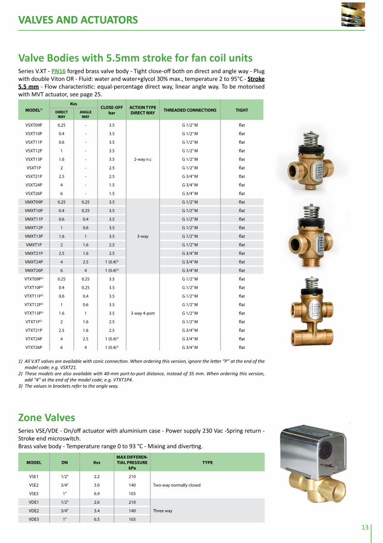
1) All V.XT valves are available with conic connection. When ordering this version, ignore the letter “P” at the end of the model code; e.g. VSXT21.
2) These models are also available with 40-mm port-to-port distance, instead of 35 mm. When ordering this version, add “4” at the end of the model code; e.g. VTXT1P4.
3) The values in brackets refer to the angle way.
Valve Bodies with 5.5mm stroke for fan coil unitsSeries V.XT - PN16 forged brass valve body - Tight close-off both on direct and angle way - Plug with double Viton OR - Fluid: water and water+glycol 30% max., temperature 2 to 95°C - Stroke 5.5 mm - Flow characteristic: equal-percentage direct way, linear angle way. To be motorised with MVT actuator, see page 25.
MoDEl1)
KvsCloSE-oFF
baraCtion tYPE DirECt WaY
tHrEaDED ConnECtionS tiGHtDirECt WaY
anGlE WaY
VSXT09P 0.25 - 3.5
2-way n.c
G 1/2” M flat
VSXT10P 0.4 - 3.5 G 1/2” M flat
VSXT11P 0.6 - 3.5 G 1/2” M flat
VSXT12P 1 - 3.5 G 1/2” M flat
VSXT13P 1.6 - 3.5 G 1/2” M flat
VSXT1P 2 - 2.5 G 1/2” M flat
VSXT21P 2.5 - 2.5 G 3/4” M flat
VSXT24P 4 - 1.5 G 3/4” M flat
VSXT26P 6 - 1.5 G 3/4” M flat
VMXT09P 0.25 0.25 3.5
3-way
G 1/2” M flat
VMXT10P 0.4 0.25 3.5 G 1/2” M flat
VMXT11P 0.6 0.4 3.5 G 1/2” M flat
VMXT12P 1 0.6 3.5 G 1/2” M flat
VMXT13P 1.6 1 3.5 G 1/2” M flat
VMXT1P 2 1.6 2.5 G 1/2” M flat
VMXT21P 2.5 1.6 2.5 G 3/4” M flat
VMXT24P 4 2.5 1 (0.4)3) G 3/4” M flat
VMXT26P 6 4 1 (0.4)3) G 3/4” M flat
VTXT09P2) 0.25 0.25 3.5
3-way 4-port
G 1/2” M flat
VTXT10P2) 0.4 0.25 3.5 G 1/2” M flat
VTXT11P2) 0.6 0.4 3.5 G 1/2” M flat
VTXT12P2) 1 0.6 3.5 G 1/2” M flat
VTXT13P2) 1.6 1 3.5 G 1/2” M flat
VTXT1P2) 2 1.6 2.5 G 1/2” M flat
VTXT21P 2.5 1.6 2.5 G 3/4” M flat
VTXT24P 4 2.5 1 (0.4)3) G 3/4” M flat
VTXT26P 6 4 1 (0.4)3) G 3/4” M flat
Zone ValvesSeries VSE/VDE - On/off actuator with aluminium case - Power supply 230 Vac -Spring return - Stroke end microswitch.Brass valve body - Temperature range 0 to 93 °C - Mixing and diverting.
MoDEl Dn KvsMaX DiFFErEn-tial PrESSUrE
kPatYPE
VSE1 1/2" 2.2 210
Two-way normally closedVSE2 3/4" 3.0 140
VSE3 1" 6.9 103
VDE1 1/2" 2.6 210
Three wayVDE2 3/4" 3.4 140
VDE3 1" 6.5 103
VALVES AND ACTUATORS
14
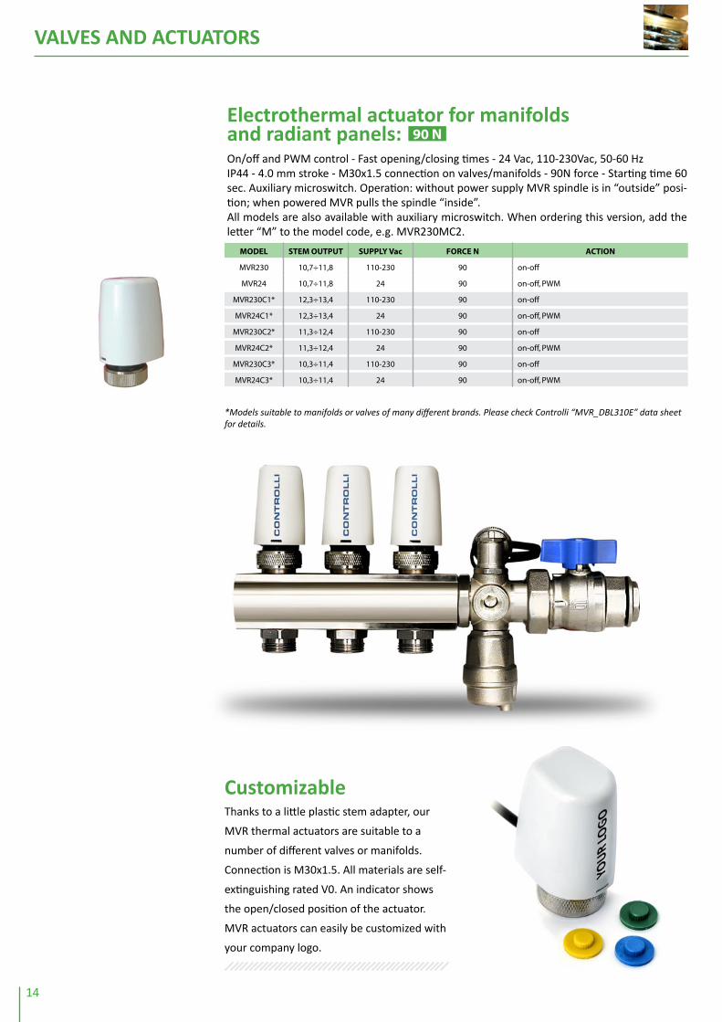
Electrothermal actuator for manifoldsand radiant panels:On/off and PWM control - Fast opening/closing times - 24 Vac, 110-230Vac, 50-60 HzIP44 - 4.0 mm stroke - M30x1.5 connection on valves/manifolds - 90N force - Starting time 60 sec. Auxiliary microswitch. Operation: without power supply MVR spindle is in “outside” posi-tion; when powered MVR pulls the spindle “inside”.All models are also available with auxiliary microswitch. When ordering this version, add the letter “M” to the model code, e.g. MVR230MC2.
MoDEl StEM oUtPUt SUPPlY Vac ForCE n aCtion
MVR230 10,7÷11,8 110-230 90 on-off
MVR24 10,7÷11,8 24 90 on-off, PWM
MVR230C1* 12,3÷13,4 110-230 90 on-off
MVR24C1* 12,3÷13,4 24 90 on-off, PWM
MVR230C2* 11,3÷12,4 110-230 90 on-off
MVR24C2* 11,3÷12,4 24 90 on-off, PWM
MVR230C3* 10,3÷11,4 110-230 90 on-off
MVR24C3* 10,3÷11,4 24 90 on-off, PWM
90 n
*Models suitable to manifolds or valves of many different brands. Please check Controlli “MVR_DBL310E” data sheet for details.
Thanks to a little plastic stem adapter, our
MVR thermal actuators are suitable to a
number of different valves or manifolds.
Connection is M30x1.5. All materials are self-
extinguishing rated V0. An indicator shows
the open/closed position of the actuator.
MVR actuators can easily be customized with
your company logo.
Customizable

VALVES AND ACTUATORS
15
2-way Globe Valves
Series 2T (threaded) - PN16 - Stroke 11.5 mm. To be motorised by MVB (2TGB.B) or MVE.S (2TGB.F) actuators, see page 25.
Values in brackets are max close-off differential pressure. In applications with steam, the value in brackets is not ap-plicable.
tight Close-offSeries VSBPM threaded valves - Modulating tight close-off valves PN16 - Thermal insulation available, see page 27 - To be motorised by MVB actuators, see page 25.
MoDEl Dn KvsStroKE
mmMaX DiFFErEntial
PrESSUrE barotHEr CHaraCtEriStiCS
VSBP3M 3/4" 6.3 16.5 2 (8.8)
- G 25 cast-iron body - Fluid temperature -5 to 95°C- Leakage 0% Kvs
VSBP4M 1" 10 16.5 2 (5.5)
VSBP5M 1 1/4" 16 16.5 2 (5.5)
VSBP6M 1 1/2" 25 16.5 2 (2.5)
VSBP8M 2” 40 16.5 1.8
1) By spring return MVHFA closed, MVHFC open. 2) For applications with ice formation on stem and packing, use the stem heater (see page 23).
MoDEl Dn Kvs
MaX DiFFErEntial PrESSUrE bar
otHEr CHaraCtEriStiCSMVB MVE506 MVE510 MVE515
MVHMVH56FA MVH56FC
MVF59A MVF59C
VSB3 3/4” 6.3 10,9 16 16 16 16 16 - G 25 cast-iron body - Brass internal parts- Female threaded connections:
fluid temperature -102) to 150 °C, with MVB max 120°C (140°C with MVB+MVBHT)
- Equal-percentage control flow cha-racteristic
- Leakage 0.03% Kvs- For MVE actuator, add AG52 linkage - For MVH actuator, add AG62 linkage
VSB4 1” 10 6,9 11,9 16 16 13,9 16
VSB5 11/4” 16 4,2 7,2 12,2 16 8,4 10,7
VSB6 11/2” 22 2,9 5,1 8,6 12,8 5,9 7,6
VSB8 2” 30 2,2 3,8 6,4 9,5 4,4 5,6
VSB8A 2” 40 2,2 3,8 6,4 9,5 4,4 5,6
VSB3F 20 6.3 10,9 16 16 16 16 16
As above but with slip-on flanges
VSB4F 25 8 6,9 11,9 16 16 13,9 16
VSB5F 32 16 4,2 7,2 12,2 16 8,4 10,7
VSB6F 40 22 2,9 5,1 8,6 12,8 5,9 7,6
VSB8F 50 30 2,2 3,8 6,4 9,5 4,4 5,6
VSB8AF 50 40 2,2 3,8 6,4 9,5 4,4 5,6
Series VSB (threaded) - VSB.F (flanged) - PN16 - Stroke 16.5 mm. To be motorised by MVB - MVF - MVH actuators, see pages 25-26 - Thermal insulation available, see page 27.
MoDEl Dn KvsMaX DiFFErEntial
PrESSUrE barotHEr CHaraCtEriStiCS
2TGB15BR00 1/2" 0.4
16
- GJL-250 cast-iron body - Brass internal parts- Equal-percentage control flow characteristic - Leakage 0 to 0.001% Kvs- Female threaded connections: fluid temperature -52) to 140 °C, with
MVB max 120°C (140 °C with MVB+MVBHT)- For MVB actuator
2TGB15BR0 1/2” 0.63
2TGB15BR1 1/2” 1
2TGB15BR2 1/2" 1.6
2TGB15BR3 1/2” 2.5
2TGB15B 1/2” 4
2TGB15FR00 1/2" 0.4
16
- GJL-250 cast-iron body - Brass internal parts- Equal-percentage control flow characteristic - Leakage 0 to 0.001% Kvs- Female threaded connections: fluid temperature -52) to 140 °C- For MVE.S actuator
2TGB15FR0 1/2” 0.63
2TGB15FR1 1/2” 1
2TGB15FR2 1/2" 1.6
2TGB15FR3 1/2” 2.5
2TGB15F 1/2” 4

VALVES AND ACTUATORS
16
Series VSBT in G25 cast-iron PN16 - Stroke 5,5mm - To be motorised by MVT actuators, see page 25.
MoDEl Dn KvsStroKE
mmMaX DiFFErEntial
PrESSUrE barotHEr CHaraCtEriStiCS
VSBT3 3/4" 6.3 5.5 2.5
- Linear control flow characteristics- Leakage 0.03% Kvs- Fluid temperature 5° to 95°C
VSBT4 1" 10 5.5 1.5
VSBT5 1 1/4" 14 5.5 0.9
VSBT6 1 1/2" 18 5.5 0.6
Model Dn Kvs
MaX DiFFErEntial PrESSUrE (bar)
MVE506 MVE510 MVE515MVH56Fa MVH56FC
2TBB15R1 1/2” 0,2 16 16 16 16
2TBB15R2 1/2” 0,5 16 16 16 16
2TBB15R3 1/2” 1 16 16 16 16
2TBB15 1/2” 2,5 16 16 16 16
2TBB20 3/4” 5 16 16 16 16
2TBB25 1” 10 10 16 16 13
2TBB32 1” 1/4 16 6 13 16 8
2TBB40 1” 1/2 25 4,5 9 16 5,5
2TBB50 2” 38 2,5 5 9 3
2TBB Series = 2-way valves, bronze body, with threaded connections up to 2”, brass plug, stainless steel stem. Temperature applications -10°C to 130°C. Rangeability 50:1.To be motorised by MVE and MVH actuators (no adapter needed).1/2” and 3/4” models are tight close-off. Maximum leakage on 1” to 2” models is 0.1% of Kvs.Stroke on 1/2” and 3/4” models is 9.5mm. Stroke on 1” to 2” models is 16mm.
MoDEl Dn KVSMaX. DiFFErEntial
PrESSUrE WitH MVt aCtUatorS
otHEr FEatUrES
2TGA20B 3/4” 5
10 barStainless steel internal
parts (seat, plug, stem)
2TGA25B 1” 8
2TGA32B 1” 1/4 11
2TGA40B 1” 1/2 18
2TGA50B 2” 30
2-way Globe Valves with high performances2TGA.B Series 2-way valves PN16 with pressure balanced plug, compact dimensions, threaded connections up to 2”, maximum temperature 130°C, suitable to applications with high close-off pressure: up to 10 bar close-off. 8,5mm stroke for MVT28, MVT44 (3 pos.) and MVT56L (proportional) actuators. See page 25.
VALVES AND ACTUATORS
17
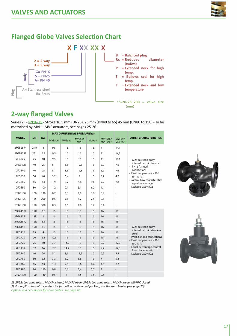
1) 2FGB: by spring return MVHFA closed, MVHFC open. 2FGA: by spring return MVHFA open, MVHFC closed. 2) For applications with eventual ice formation on stem and packing, use the stem heater (see page 20).Options and accessories for valve bodies: see page 20.
2-way flanged valvesSeries 2F - PN16-25 - Stroke 16.5 mm (DN25), 25 mm (DN40 to 65) 45 mm (DN80 to 150) - To be motorised by MVH - MVE actuators, see pages 25-26
MoDEl Dn Kvs
MaX DiFFErEntial PrESSUrE bar
otHEr CHaraCtEriStiCSMVE506 MVE510
MVE515 MVH
MVH3KMVH56FA MVH56FC
MVF59A MVF59C
2FGB25R4 25 R 4 9,5 16 16 16 11 14,1
- G 25 cast-iron body internal parts in bronze
- PN16 flanged connections
- Fluid temperature: - 102) to 150 °C
- Control flow characteristics equal-percentage
- Leakage 0.03% Kvs
2FGB25R7 25 I 6.3 9,5 16 16 16 11 14,1
2FGB25 25 10 9,5 16 16 16 11 14,1
2FGB40R 40 25 5,1 8,6 12,8 16 5,9 7,6
2FGB40 40 25 5,1 8,6 12,8 16 5,9 7,6
2FGB50 50 40 3,2 5,4 8 16 3,7 4,7
2FGB65 65 63 1,9 3,2 4,8 9,6 2,2 2,8
2FGB80 80 100 1,2 2,1 3,1 6,2 1,4 -
2FGB100 100 130 0,7 1,3 1,9 3,9 0,9 -
2FGB125 125 200 0,5 0,8 1,2 2,5 0,5 -
2FGB150 150 300 0,3 0,5 0,8 1,7 0,4 -
2FGA15R0 15R 0.6 16 16 16 16 16 16
- G 25 cast-iron body internal parts in stainless steel
- PN16 flanged connections- Fluid temperature: - 102)
to 200 °C- Equal-percentage control
flow characteristic- Leakage 0.02% Kvs
2FGA15R1 15R 1 16 16 16 16 16 16
2FGA15R2 15R 1.6 16 16 16 16 16 16
2FGA15R3 15R 2.5 16 16 16 16 16 16
2FGA15 15 4 16 16 16 16 16 16
2FGA20 20 6.3 12,6 16 16 16 15,1 16
2FGA25 25 10 7,7 14,2 16 16 9,2 12,3
2FGA32 32 16 7,7 14,2 16 16 9,2 12,3
2FGA40 40 24 5,1 9,6 13,5 16 6,2 8,3
2FGA50 50 32 3,3 6,2 8,8 16 4 5,4
2FGA65 65 63 1,3 2,5 3,6 8,4 1,6 2,2
2FGA80 80 110 0,8 1,6 2,4 5,5 1 -
2FGA100 100 140 0,5 1 1,5 3,5 0,6 -
flanged Globe valves selection Chart
X F XX XX X
2 = 2 way3 = 3 way
G= PN16S = PN25A= PN 40
15-20-25..200 = valve size (mm)
B = Balanced plugRx = Reduced diameter
(x=Kvs)P = Extended neck for high
temp.S = Bellows seal for high
temp.T = Extended neck and low
temperature
Bod
y
A= Stainless steelB= BrassPl
ug

VALVES AND ACTUATORS
18
1) 2FSA: by spring return MVHFA closed, MVHFC open. 2FAA: by spring return MVHFA open, MVHFC closed. 2) For applications with eventual ice formation on stem and packing, use the stem heater (see page 23).3) For fluid applications with temperature below -10 °C, when ordering, add “T” instead of “P” to model, e.g. 2FAA40T.
Series 2F - PN16-25 - Stroke 16.5 mm (DN25), 25 mm (DN40 to 65) 45 mm (DN80 to 150) - To be motorised by MVE - MVF actuators, see pages 25-26.
MoDEl Dn Kvs
MaX DiFFErEntial PrESSUrE bar
otHEr CHaraCtEriStiCSMVE506 MVE510
MVE515 MVH
MVH3KMVH56FA MVH56FC
MVF59A MVF59C
2FSA25R4 25 R 4 18,5 25 25 25 21,6 25- Spheroidal cast-iron body
internal parts in stainless steel
- PN25 flanged connections
- Fluid temperature: -102) to -230°C
- Equal-percentage control flow characteristic
- Leakage 0.02% Kvs
2FSA25R7 25I 6.3 9,3 15,8 21,6 25 10,9 13,9
2FSA25 25 10 9,3 15,8 21,6 25 10,9 13,9
2FSA32 32 16 6,3 10,7 14,6 25 7,3 9,4
2FSA40 40 25 4,5 7,7 10,5 23,1 5,3 6,7
2FSA50 50 40 2,8 4,9 6,7 14,8 3,3 4,3
2FSA65 65 63 1,6 2,8 3,9 8,7 1,9 2,5
2FAA15R2 15 R 1.6 30 30 30 30 30 30
- Fe 52 steel body internal parts in stainless steel
- PN40 flanged connections
- Fluid temperature: - 102) to 230 °C
- Equal-percentage control flow characteristic
- Leakage 0.02% Kvs
2FAA15 15 4 14,5 32,2 30 30 18,8 27
2FAA20 20 6.3 8,6 19,1 28,4 30 11,1 16
2FAA25 25 10 5,2 11,7 17,4 30 6,8 9,8
2FAA32 32 16 5,2 11,7 17,4 30 6,8 9,8
2FAA40 40 24 3,5 7,9 11,8 29,3 4,5 6,6
2FAA50 50 32 2,2 5,1 7,7 19,1 2,9 4,3
2FAA65 65 63 0,9 2,1 3,1 7,9 1,2 1,7
2FAA80 80 110 0,5 1,3 2 5,2 0,7 -
2FAA15PR2 15 R 1.6 30 30 30 30 30 30- Fe 52-steel body with
extended neck internal parts in stainless steel with greaser and special gaskets for high temperatures
- PN40 flanged connections
- Fluid temperature: - 203) to 350°C
- Equal-percentage control flow characteristic
- Leakage 0.02% Kvs
2FAA15P 15 4 14,5 32,2 30 30 18,8 27
2FAA20P 20 6.3 8,6 19,1 28,4 30 11,1 16
2FAA25P 25 10 5,2 11,7 17,4 30 6,8 9,8
2FAA32P 32 16 5,2 11,7 17,4 30 6,8 9,8
2FAA40P 40 24 3,5 7,9 11,8 29,3 4,5 6,6
2FAA50P 50 32 2,2 5,1 7,7 19,1 2,9 4,3
2FAA65P 65 63 0,9 2,1 3,1 7,9 1,2 1,7
2FAA80P 80 110 0,5 1,3 2 5,2 0,7 -

VALVES AND ACTUATORS
19
1) By spring return MVHFA closed, MVHFC open.2) For applications with eventual ice formation on stem and packing, use the stem heater (see page 20).
1) By spring return MVHFA closed, MVHFC open.2) For applications with eventual ice formation on stem and packing, use the stem heater (see page 23).
2-way Balanced Plug ValvesSeries 2F.B PN16-25-40 Stroke 16.5 mm (DN25), 25 mm (DN40 to 65) 45 mm (DN80 to 150). To be motorised by MVH-MVE actuators, see pages 25-26.
MoDEl Dn Kvs
MaX DiFFErEntial PrESSUrE bar
otHEr CHaraCtEriStiCSMVF58 MVF515 MVH
MVHFA/C
MVF59AMVF59C
2FGB65B 65 63 10,8 16 16 14 16- G25 cast iron body, brass plug- PN16 flanged connections- Fluid temperature: -102) to 150°C - Equal-percentage control characteri-
stic - Leakage 0.03% Kvs
2FGB80B 80 100 8,1 16 16 10,7 15,7
2FGB100B 100 130 5,4 14 16 7,5 11,5
2FGB125B 125 200 3,5 10,4 16 5,2 8,4
2FGB150B 150 300 2,2 7,9 12,9 3,5 6,2
2FSA25BR4 25R 4 25 25 25 25 25
- Spheroidal cast iron body, stainless steel internal parts
- PN25 flanged connections - Fluid temperature: -102) to 230°C- Equal-percentage control characteri-
stic - Leakage 0.02% Kvs
2FSA25BR7 25I 6.3 25 25 25 25 25
2FSA25B 25 10 25 25 25 25 25
2FSA32B 32 16 25 25 25 25 25
2FSA40B 40 25 25 25 25 25 25
2FSA50B 50 40 18,4 25 25 25 25
2FSA65B 65 63 12,2 25 25 17,7 25
2FSA80B 80 80 8,3 25 25 12,8 -
2FAA25B 25 10 30 30 30 30 30
- Steel body and stainless steel internal parts
- PN40 flanged connections- Fluid temperature: -202) to 230°C- Equal-percentage control characteri-
stic - Leakage 0.02% Kvs
2FAA32B 32 16 30 30 30 30 30
2FAA40B 40 25 30 30 30 30 30
2FAA50B 50 40 30 30 30 30 30
2FAA65B 65 63 27,7 30 30 30 30
2FAA80B 80 100 21,1 30 30 28,2 30
2FAA100B 100 160 14,9 30 30 20,4 30
2FAA125B 125 200 11,1 29,6 30 15,6 -
2FAA125B 6,5 19,2 30 9,6 -
2FAA125B 4,3 14,4 23,3 6,7 -
2-way Double-seat ValvesSeries 2FGA.B-2FAA.B - Stroke 45 mm - To be motorised by MVH-MVE actuators, see pages 25-26.
MoDEl Dn Kvs
MaX DiFFErEntial PrESSUrE bar
otHEr CHaraCtEriStiCS
MVE510MVE515
MVHMVH56FA MVH56FC
2FAA150B(PN25)
150 300 2.9 12 (17.5) 12 (17.5)
- Fe 52 Steel body and stainless steel internal parts - PN40 flanged connections- Fluid temperature: -102) ÷ 230°C- Equalpercentage control characteristic- Leakage 0.12% Kvs
2FGA200B(PN16)
200 500 1.8 8 (11.6) 8 (11.6)
- G25 cast iron body, stainless steel internal parts- PN16 flanged connections- Fluid temperature: -102) to 200°C - Equalpercentage control characteristic- Leakage 0.12% Kvs

VALVES AND ACTUATORS
20
1) For applications with eventual ice formation on stem and packing, use the stem heater (see page 23).
1) By spring return MVHFA closed, MVHFC open.2) For applications with eventual ice formation on stem and packing, use the stem heater (see page 23).
Series VMB (threaded) - VMBF (flanged) - PN16. To be motorised by MVB - MVE - MVH actua-tors, see pages 25-26. - Thermal insulation available, see page 27.
MoDEl Dn Kvs
MaX DiFFErEntial PrESSUrE bar
otHEr CHaraCtEriStiCSMVB MVE506 MVE510
MVE515 MVH
MVH56FA MVH56FC
MVF59A MVF59C
VMB3 3/4” 6.3 2,7 13,1 16 16 15,7 16- G 25 cast-iron body- Brass internal parts- Female threaded connections- Fluid temperature: -102)÷150°C
(with MVB max 120 °C, with MVB+MVBHT max 140 °C)
- Control characteristic: equal-per-centage on direct way, linear on angle way
- Leakage 0.03% Kvs- For MVF actuator, add AG52 linkage - For MVH actuator, add AG62 lin-
kage
VMB4 1” 10 1,8 8,7 15,7 16 10,4 13,7
VMB5 11/4” 16 1,1 5,5 9,9 13,8 6,6 8,6
VMB6 11/2” 22 0,8 4 7,2 10 4,7 6,2
VMB8 2” 30 0,6 3 5,4 7,5 3,6 4,7
VMB8A 2” 40 0,6 3 5,4 7,5 3,6 4,7
VMB3F 20 6.3 2,7 13,1 16 16 15,7 16
As above with NP16 slip-on flanges
VMB4F 25 8 1,8 8,7 15,7 16 10,4 13,7
VMB5F 32 16 1,1 5,5 9,9 13,8 6,6 8,6
VMB6F 40 22 0,8 4 7,2 10 4,7 6,2
VMB8F 50 30 0,6 3 5,4 7,5 3,6 4,7
VMB8AF 50 40 0,6 3 5,4 7,5 3,6 4,7
1) The values in brackets refer to angle way.
tight Close-offSeries VMBPM threaded valves - Tight close-off modulating valves PN16 - Thermal insulation available, see page 27 - To be motorised by MVB actuators, page 25.
MoDEl Dn KvsStroKE
mmMaX DiFFErEntial PrESSUrE bar otHEr CHaraCtEriStiCS
VMBP3M 3/4” 6.3 16.5 8.8
- G25 cast iron valve body- Fluid temperature -5 to 95°C- Leakage 0% Kvs
VMBP4M 1" 10 16.5 5.5
VMBP5M 11/4” 16 16.5 3.5
VMBP6M 11/2” 25 16.5 2.5
VMBP8M 2” 40 16.5 1.8
Series 3T (threaded) - PN16 - Stroke 11.5 mm. To be motorised by MVB (3TGB.B) - MVE.S (3TGB.F) actuators, see page 25.
MoDEl Dn KvsMaX DiFFErEntial
PrESSUrE baraCtUatorS otHEr CHaraCtEriStiCS
3TGB15BR2 1/2" 1.6
16 For MVB actuator
- GJL-250 cast-iron body - Brass internal parts- Equal-percentage control flow cha-
racteristic - Leakage 0 to 0.001% Kvs- Female threaded connections: fluid
temperature -51) to 140 °C, with MVB max 120°C (140 °C with MVB+MVBHT)
3TGB15BR3 1/2” 2.5
3TGB15B 1/2” 4
3TGB15FR2 1/2" 1.6
16 For MVE.S actuator3TGB15FR3 1/2” 2.5
3TGB15F 1/2” 4
3-way Globe Valves
VALVES AND ACTUATORS
21
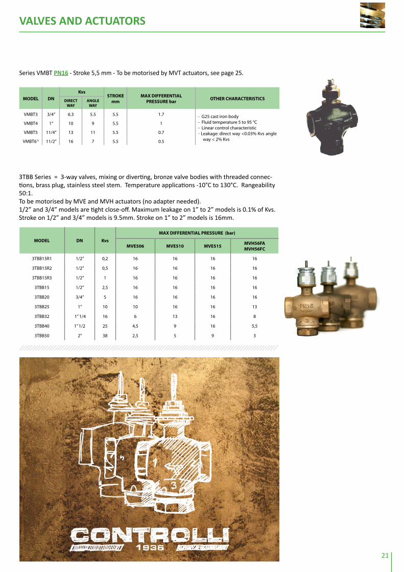
Series VMBT PN16 - Stroke 5,5 mm - To be motorised by MVT actuators, see page 25.
MoDEl Dn
KvsStroKE
mmMaX DiFFErEntial
PrESSUrE barotHEr CHaraCtEriStiCSDirECt
WaYanGlE
WaY
VMBT3 3/4” 6.3 5.5 5.5 1.7 - G25 cast iron body- Fluid temperature 5 to 95 °C- Linear control characteristic- Leakage: direct way <0.03% Kvs angle
way < 2% Kvs
VMBT4 1” 10 9 5.5 1
VMBT5 11/4” 13 11 5.5 0.7
VMBT61) 11/2” 16 7 5.5 0.5
MoDEl Dn Kvs
MaX DiFFErEntial PrESSUrE (bar)
MVE506 MVE510 MVE515MVH56Fa MVH56FC
3TBB15R1 1/2” 0,2 16 16 16 16
3TBB15R2 1/2” 0,5 16 16 16 16
3TBB15R3 1/2” 1 16 16 16 16
3TBB15 1/2” 2,5 16 16 16 16
3TBB20 3/4” 5 16 16 16 16
3TBB25 1” 10 10 16 16 13
3TBB32 1” 1/4 16 6 13 16 8
3TBB40 1” 1/2 25 4,5 9 16 5,5
3TBB50 2” 38 2,5 5 9 3
3TBB Series = 3-way valves, mixing or diverting, bronze valve bodies with threaded connec-tions, brass plug, stainless steel stem. Temperature applications -10°C to 130°C. Rangeability 50:1.To be motorised by MVE and MVH actuators (no adapter needed).1/2” and 3/4” models are tight close-off. Maximum leakage on 1” to 2” models is 0.1% of Kvs.Stroke on 1/2” and 3/4” models is 9.5mm. Stroke on 1” to 2” models is 16mm.

VALVES AND ACTUATORS
22
The values in brackets are max close-off differential pressure. 1) By spring return MVHFA closed, MVHFC open.2) For applications with eventual ice formation on stem and packing, use the stem heater (see page 23).
Series 3F PN16-25 - Stroke 16.5 mm (DN25), 25mm (DN40-65), 45mm (DN80-150) - To be mo-torised by MVE-MVH actuators, see pages 25-26.
MoDEl Dn Kvs
MaX DiFFErEntial PrESSUrE barotHEr CHaraCtEri-
StiCSMVE506 MVE510MVE515
MVHMVH3K
MVH56FA MVH56FC
MVF59A MVF59C
3FGB25R4 25 R 4 7,1 12,7 16 16 8,4 11,1
- G25 cast-iron body brass internal parts
- PN16 flanged connec-tions
- Fluid temperature: - 102)
to 150 °C- Control flow characteri-
stic: direct way: equal-percentage, angle way: linear
- Leakage: direct-way: 0.03% Kvs, angle way: 2% Kvs
3FGB25R7 25 I 6.3 7,1 12,7 16 16 8,4 11,1
3FGB25 25 10 7,1 12,7 16 16 8,4 11,1
3FGB40R19 40 R 19 4 7,2 10 16 4,7 6,2
3FGB40 40 25 4 7,2 10 16 4,7 6,2
3FGB50 50 40 2,5 4,6 6,4 14,5 3 4
3FGB65 65 63 1,5 2,7 3,8 8,6 1,8 2,4
3FGB80 80 100 1 1,8 2,5 5,7 1,2 -
3FGB100 100 130 0,6 1,1 1,6 3,6 0,8 -
3FGB125 125 200 0,4 0,7 1 2,3 0,5 -
3FGB150 150 300 0,3 0,5 0,7 1,6 0,3 -
3FSA25R4 25 R 4 9,5 22,3 25 25 12,6 18,5- G-308 spheroidal cast-
iron body stainless ste-el internal parts
- PN25 flanged connec-tions
- Fluid temperature: -102) to 230 °C
- Control flow characte-ristic: equalpercenta-ge (DN25÷65) linear (DN80), angle way line-ar
- Leakage 0.02% Kvs
3FSA25R7 25 I 6.3 4,7 11,2 17 25 6,3 9,3
3FSA25 25 10 4,7 11,2 17 25 6,3 9,3
3FSA32 32 19 3,2 7,6 11,5 25 4,2 6,3
3FSA40 40 25 2,2 5,4 8,2 20,9 3 4,5
3FSA50 50 40 1,4 3,4 5,2 13,3 1,9 2,8
3FSA65 65 63 0,8 2 3,1 7,8 1,1 1,6
3FSA80 80 110 0,7 1,5 2,2 5,4 0,9 -
3FSA25SR4 25 R 4 5 5 5 5 5 5- G 308 spheroidal cast-
iron body stainless ste-el internal parts with bellows seal
- PN25 flanged connec-tions
- Fluid temperature: -102) to 300 °C
- Control flow characte-ristic: equal percenta-ge (DN25÷65) linear (DN80), angle way line-ar
- Leakage 0.02% Kvs
3FSA25SR7 25 I 6.3 5 5 5 5 5 5
3FSA25S 25 10 5 5 5 5 5 5
3FSA32S 32 16 4,8 5 5 5 5 5
3FSA40S 40 25 3,5 5 5 5 4,2 5
3FSA50S 50 40 2,2 4,3 5 5 2,7 3,7
3FSA65S 65 63 1,3 2,5 3,6 5 1,6 2,2
3FSA80S 80 110 0,9 1,7 2,4 5 1,1 -

VALVES AND ACTUATORS
23
1) By spring return MVHFA closed direct way, MVHFC open2) For fluid applications with temperature below -10 °C, when ordering, add “T” , instead of “P” to model, e.g. 3FAA40T
Series 3F PN40 - Stroke 16.5 mm (DN25), 25mm (DN40-65), 45mm (DN80-125) - To be motor-ised by MVE-MVH actuators, see pages 25-26.
MoDEl Dn Kvs
MaX DiFFErEntial PrESSUrE bar
otHEr CHaraCtEriStiCSMVE506 MVE510
MVE515 MVH
MVH3KMVH56FA MVH56FC
MVF59A MVF59C
3FAA25R4 25 R 4 6 13 19,2 30 7,7 11
- Fe 52 steel body stainless steel internal parts
- PN40 flanged connections- Fluid temperature: -102) to
230 °C- Control flow characteristic:
linear- Leakage 0.02% Kvs
3FAA25R7 25 I 6.3 6 13 19,2 30 7,7 11
3FAA25 25 10 6 13 19,2 30 7,7 11
3FAA32 32 16 3,8 8,2 12,1 30 4,9 6,9
3FAA40 40 22 2,5 5,4 7,9 19,4 3,2 4,5
3FAA50 50 32 1,8 3,8 5,6 13,7 2,3 3,2
3FAA65 65 70 1 2,3 3,3 8,1 1,3 1,9
3FAA80 80 110 0,7 1,5 2,2 5,4 0,9 -
3FAA100 100 140 0,4 1 1,4 3,4 0,6 -
3FAA125 125 250 0,3 0,6 0,9 2,2 0,4 -
3FAA25PR4 25 R 4 6 13 19,2 30 7,7 11
- Fe 52 steel body internal parts in AISI 316 stainless steel with grease-cap and special seals for high tem-perature
- PN40 flanged connections- Fluid temperature: - 202) to
350 °C- Control flow characteristics:
linear- Leakage 0.02% Kvs
3FAA25PR7 25 I 6.3 6 13 19,2 30 7,7 11
3FAA25P 25 10 6 13 19,2 30 7,7 11
3FAA32P 32 16 3,8 8,2 12,1 30 4,9 6,9
3FAA40P 40 22 2,5 5,4 7,9 19,4 3,2 4,5
3FAA50P 50 32 1,8 3,8 5,6 13,7 2,3 3,2
3FAA65P 65 70 1 2,3 3,3 8,1 1,3 1,9
3FAA80P 80 110 0,7 1,5 2,2 5,4 0,9 -
3FAA100P 100 140 0,4 1 1,4 3,4 0,6 -
3FAA125P 125 250 0,3 0,6 0,9 2,2 0,4 -
Accessories(Supplied separately from the valve body, mounting to be carried out by the user)
MoDEl DESCriPtion
AG22 Linkage kit for MVB on V500
AG50 Linkage kit for MVE-MVH on VMB16-VBG-VSG (old type) up to DN65 valves
AG51 Linkage kit for MVE-MVH on other SS-VS-DS-VM-3V (old type) flanged valves
AG52 Linkage kit for MVE-MVH on VSB-VMB, VSB.F-VMB.F valves (pages 52, 56)
AG60-20 Linkage kit for MVE on Honeywell valves
AG60-03 Linkage kit for MVE on Landis valves
AG53 Linkage kit for MVE on Satchwell valves
AG66/AG67 Linkage kit for MVE on Johnson Controls valves
AG60-07 Linkage kit for MVE on Danfoss valves
AG62 Linkage kit for MVH on VSB-VMB, VSB.F-VMB.F valves (pages 52, 56)
AG63 Linkage kit for MVE.S on VSB-VMB, VSB.F-VMB.F valves (pages 52, 56)
AG64 Linkage kit for MVH on SS-DS-VM-3V (old type) up to DN65 valves with MVLHT spacer
AG65 Linkage kit for MVH on SS-DS-VM-3V (old type) DN >80 valves with MVLHT spacer
244Stem heater for VSB/VSB-F- VMB/VMB-F valves motorised by MVB actuator or MVE-MVH actuators with AG52-AG62, supply 24 V a.c.
248 As above for MVH-MVE with 2F-3F flanged valves
3-way Globe Valves

this page intentionally left blank

VALVES AND ACTUATORS
25
Actuators for Zone Valves and Terminal unit ValvesSeries MVT2./4. - Bidirectional type - Driving signal from any floating controller, e.g. DIGITROLL 7000 NR732xB-734xBx, RA735 - Stroke 5.5 mm, stroke time 117 s. - For V.XT - V.BT valve bodies - Protection IP43. Series MVT5. - Bidirectional type with microprocessor module for proportional signal Vdc - 24 Vac power supply - Stroke 5 mm to 5,5 mm, stroke time 117 s. - For V.XT - V.BT valve bodies - Protection IP43.
MoDElPoWEr SUPPlY
VacConSUMPtion
VaotHEr CHaraCtEriStiCS
MVT28 230 5 3-position control
MVT44 24 0.5 3-position control
MVT56 24 10 to 10/ 6 to 10/ 1 to 5/ 2 to 10/ 4 to 7/ 6 to 9/8 to 11 Vdc proportional control - direct/reverse action
MVT56L 24 1 Same as MVT56 but Stroke 8,5 mm
MVT56S 24 1 Same as MVT56 but Stroke 5 mm
MVT57 24 1 0 to 10 Vdc - proportional control - only direct action
Globe Valve ActuatorsSeries MVB - Bidirectional motor for V.B threaded ½” to 2” and flanged 15 to 50 mm valve bod-ies - Supplied with linkage for mounting on 2T-3T and V.B-V.BF valve bodies - IP50 protection.
MoDEl tiMinG s.SUPPlY
VacConSUMPtion
VaotHEr CHaraCtEriStiCS
MVB22 37 230 5
on/off, floatingMVB26 60 230 5
MVB28 370 230 5
MVB46 60 24 5
MVB46P As MVB46 with 1 kOhm auxiliary potentiometer
MVB36 60 24 5 proportional potentiometric
MVB52 37 24 5 Vdc/ current proportional control. Ranges: 6 to 9, 4 to 7, 8 to 11, 0 to 10, 2 to 10, 1 to 5 Vdc, 4 to 20 mA. Default setting: 0 to 10Vdc MVB56 60 24 5
MVBAV MVB mounting on valvebody
200 n
450 n
Actuators
Globe Valve ActuatorsMVE series. Innovative actuator with brush-less motor suitable to all Con-trolli valves.3 pos. & 0-10V proportional control in a single model. Self stroking, self calibrating up to 60mm stroke. IP54 Universal! Suitable to many valves also from other manufacturers (see the list of adapters on page 23)
MoDEl ForCE (n) PoWEr SUPPlY ConSUMPtion
(Va)otHEr FEatUrES
MVE506 600 24Vac/dc 13 3-position and/or proportional control (selectable).Ranges: 6 to 9/4 to 7/ 8 to 11/0 to10/2 to 10/1 to 5 Vdc; current 4 to 20 mA
MVE510 1000 24Vac/dc 18
MVE515 1500 24Vac/dc …
MVE506S 600 24Vac/dc 13 3-position and/or proportional control (selectable).Ranges: 6 to 9/4 to 7/ 8 to 11/0 to10/2 to 10/1 to 5 Vdc; current 4 to 20 mA Short bracket
MVE510S 1000 24Vac/dc 18
MVE515S 1500 24Vac/dc …
600n - 1000n - 1500n
Soon available also with 230 Vac power supply

VALVES AND ACTUATORS
26
Globe Valve Actuators with Spring ReturnSeries MVF59 - Brushless motor for any Controlli valve, flanged DN15÷65 (MVF59) and threa-ded 1/2”÷2” (MVF59.S short bracket with linkage AG63) - Self-stroking, self-adjusting - Power supply 24Vac. For mounting on VSB-VSB-F VMB-VMB-F valves, add linkage AG52 for MVF59 or AG63 for MVF59.S. For 2T-3T valves (MVF.S) no linkage is required - Linkages to valves from other manufacturers available - Contact our customer service for details.
Globe Valve ActuatorsSeries MVH - For all valve bodies, self-adjusting stroke 10 to 45 mm (9 to 50 mm for MVH56F) - For VSB-VSB.F VMB-VMB.F valves only, add linkage AG62, - Manual override - Protection IP55.
MoDEl
tiMinG DEPEnDinG on ValVE StroKE s. SUPPlY
Vac
Con-SUMPtion
Va
ForCEn
aCtion
16.5 25 45
MVH26 22 33 60 230 12
1.500
on/off floatingMVH46 22 33 60 24 12
MVH36 22 33 60 24 12 proportional potentiometric
MVH56 22 33 60 24 12proportional control selectable rangefor industrial applications
MVH56F 22 33 60 24 12 3-position and/or proportional control (selectable) Ranges: 6 to 9/4 to 7/8 to 11/0 to 10/2 to 10/1 to 5 Vdc; current 4 to 20 mA. Default setting: 0 to 10Vdc
MVH3K 26 40 70 24 25 3.000
MVHAV MVH assembly on valve body
Note: The values in brackets indicate the return time by spring return. By spring return: MVHFA closes two-way valves and direct way in three-way valves, MVHFC opens two-way valves and direct way in three-way valves. This is valid for all valves except 2FGA-2FGA.B-2FAA-2FAA150B in which it happens the opposite.
MoDEl
tiMinG DEPEnDinG on ValVE StroKE s. SUPPlY
Vac
Con-SUMPtion
VaaCtion
otHEr CHaraCtE-riStiCS
16.5 25 45
MVH56FA17
(45)25
(60)48
(114)24 15 Vdc/ mA proportio-
nal control or floa-ting control. Default setting: 0 to 10Vdc
with spring return stem up
MVH56FC17
(45)25
(60)48
(114)24 15
with spring return stem down
Globe Valve Actuators with Spring ReturnSeries MVH - For all valve bodies, self-adjusting stroke 9 to 50 mm - Direct-reverse action - For VSB-VSBF VMB-VMBF valves only, add linkage AG62 - Protection IP55.
MoDElProtECtion
DEGrEEaCtion otHEr CHaraCtEriStiCS
MVF59A IP543-position and/or proportional control (selectable). Ranges: 6 to 9/4 to 7/ 8 to 11/0 to 10/2 to 10/1 to 5 Vdc; current 4 to 20 mA
with spring return stem upMVF59AW IP65
MVF59C IP54with spring return stem down
MVF59CW IP65
MVF59AS IP54 3-position and/or proportional control (selectable). Ranges: 6 to 9/4 to 7/ 8 to 11/0 to 10/2 to 10/1 to 5 Vdc; current 4 to 20 mAShort bracket*
with spring return stem upMVF59AWS IP65
MVF59CS IP54with spring return stem down
MVF59CWS IP65
1500 n-3000 n
700 n
900 n
*
VALVES AND ACTUATORS
27
All accessories, except MVBD, are supplied separately. Mounting is carried out by the user.
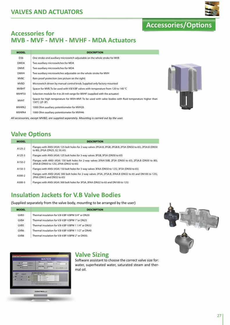
Accessories for MVB - MVf - MVH - MVHf - MDA Actuators
MoDEl DESCriPtion
D36 One stroke-end auxiliary microswitch adjustable on the whole stroke for MVB
DMDA Two auxiliary microswitches for MDA
DMVE Two auxiliary microswitches for MDA
DMVH Two auxiliary microswitches adjustable on the whole stroke for MVH
MVBC Rain-proof protection (see picture on the right)
MVBD Microswitch driven by manual control knob. Supplied only factory-mounted
MVBHT Spacer for MVB. To be used with V.B/V.BF valves with temperature from 120 to 140 °C
MVHFS5 Selection module for 4 to 20 mA range for MVHF (supplied with the actuator)
MVHTSpacer for high temperature for MVH-MVF. To be used with valve bodies with fluid temperature higher than 150°C (2F-3F)
MVHPA2 1000 Ohm auxiliary potentiometer for MVH26
MVHPA4 1000 Ohm auxiliary potentiometer for MVH46
Valve SizingSoftware assistant to choose the correct valve size for: water, superheated water, saturated steam and ther-mal oil.
Accessories/options
valve optionsMoDEl DESCriPtion
A125-2Flanges with ANSI (ASA) 125 bolt holes for 2-way valves 2FGA.B, 2FGB, 2FGB.B, 2FSA (DN50 to 65), 2FSA.B (DN50 to 80), 2FGA (DN25, 32, 50, 65)
A125-3 Flanges with ANSI (ASA) 125 bolt holes for 3-way valves 3FGB, 3FSA (DN50 to 65)
A150-2Flanges with ANSI (ASA) 150 bolt holes for 2-way valves 2FAA150B, 2FSA (DN50 to 65), 2FSA.B (DN50 to 80), 2FAA.B (DN50 to 125), 2FAA (DN32 to 65)
A150-3 Flanges with ANSI (ASA) 150 bolt holes for 3-way valves 3FAA (DN50 to 125), 3FSA (DN50 to 65)
A300-2Flanges with ANSI (ASA) 300 bolt holes for 2-way valves 2FSA, 2FSA.B, 2FAA.B (DN32 to 65 and DN100 to 125), 2FAA (DN15 and DN32 to 65)
A300-3 Flanges with ANSI (ASA) 300 bolt holes for 3FSA, 3FAA (DN32 to 65 and DN100 to 125)
Insulation Jackets for v.B valve Bodies(Supplied separately from the valve body, mounting to be arranged by the user)
MoDEl DESCriPtion
GVB3 Thermal insulation for V.B-V.BF-V.BPM 3/4" or DN20
GVB4 Thermal insulation for V.B-V.BF-V.BPM 1” or DN25
GVB5 Thermal insulation for V.B-V.BF-V.BPM 1 1/4" or DN32
GVB6 Thermal insulation for V.B-V.BF-V.BPM 1 1/2" or DN40
GVB8 Thermal insulation for V.B-V.BF-V.BPM 2" or DN50.

VALVES AND ACTUATORS
28
Shoe ValvesSeries M - Cast-iron NP6 - To be motorised by MDB24-44-54 actuators, see page 30, fitted with AM72.
MoDEl Dn KvsMaX DiFFErEntial PrESSUrE
barotHEr CHaraCtEriStiCS
M3(NP6)
threaded
1” 30 100 - THREE-WAY- NP 6 cast-iron valve body- Female threaded connections- Outlet from angle-way- Fluid temperature: 110 °C max
11/4” 37 100
11/2” 38 100
2” 45 100
M3(NP6)
flanged
40 38 100
As above, with flanged connections
50 70 100
65 80 80
80 90 50
100 110 30
125 120 20
M4(NP6)
threaded
1” 30 100- FOUR-WAY NP 6 cast-iron valve body- Female threaded connections- Fluid temperature: 110 °C max
11/4” 37 100
11/2” 40 100
2” 45 100
M4(NP6)
flanged
50 70 100
As above, with flanged connections65 80 100
80 90 80
100 110 30
Butterfly valvesSeries VFA - The valves are ready for mounting on MDA actuators, see page 29. They can also be motorized by MDL actuators (page 29) by means of AF25 adapter.
MoDEl Dn KvsMaX DiFFErEntial PrESSUrE bar
otHEr CHaraCtEriStiCSMDa22/42/52 MDa24/44/54
VFA(PN10)
25 27.8
600
-
- Spheroidal cast-iron body (EN-JS1030)- Shaft tight O-Ring- Seat EPDM- Fluid temp.: -10 to 100°C- Close-off leakage: leakage rate A (DIN EN
12266-1)
32 28.5 -
40 58 -
50 107 -
65 201 -
80 336 -
100 576 -
125 840 - 600
150 1295 -300
200 2470 -
Butterfly/shoe valves

VALVES AND ACTUATORS
29
VARIANTS: in case the MDL2./4. actuators are needed to be supplied with 1 KOhm auxiliary potentiometer, add PA2 for
MDL20, PA4 for MDL40 and PA6 for MDL60: e.g. MDL24PA2, MDL46PA4 or MDL66PA6. In special applications, the actua-
tors can be supplied with 2 or 3 auxiliary potentiometers.
damper Actuators for Butterfly valvesSeries MDL - Bidirectional motor- Input signal P.C. board - Power consumption 12VA - 2 output shafts: main and secondary shaft Ø 9.5 x 9.5 mm - MDL30-50 angular travel set at 90°adjustable between 55 and 160°- MDL20-40-60 angular travel set at 90°ad-justable between 0 and 160° - Force 500 N - Manual override - IP 55.
MoDEltiMinG
(s. For 90°)torQUE
nm
aDJUStaBlE anGUlar
traVEl
SUPPlY Vac
MaX DaMPEr
SUrFaCE m2
aCtion
MDL22 15 - 27 6 0 to 160 230 1.2 on/off, floating
MDL24 45 - 80 20 0 to 160 230 4 “
MDL26 60 - 107 30 0 to 160 230 6 “
MDL42 15 - 27 6 0 to 160 24 1.2 “
MDL44 45 - 80 20 0 to 160 24 4 “
MDL46 60 - 107 30 0 to 160 24 6 “
MDL62 15 - 27 6 0 to 160 110 1.2 “
MDL64 45 - 80 20 0 to 160 110 4 “
MDL66 60 - 107 30 0 to 160 110 6 “
MDL32 15 - 27 6 55 to 160 24 1.2proportional-potentio-metric (165 Ohm)
MDL34 45 - 80 20 55 to 160 24 4
MDL36 60 - 107 30 55 to 160 24 6
MDL52 15 - 27 6 55 to 160 24 1.2 Vdc/current proportio-nal control. Ranges: 6 to 9, 4 to 7, 8 to 11, 0 to 10, 1 to 5 Vdc, or current 4 to 20 mA
MDL54 45 - 80 20 55 to 160 24 4
MDL56 60 - 107 30 55 to 160 24 6
optionsMoDEl DESCriPtion
MDLS5 Electronic card input signal, range 6 to 9, 4 to 7, 8 to 11, 1 to 5 V d.c., 4 to 20 mA for MDL32/34/36
MDLV5Electronic card input signal, range 0 to 10 V d.c., 4 to 20 mA with adjustable start point and span for MDL32/34/36
DMDL Two auxiliary microswitches SPDT 10 (3) A - 240 V a.c. adjustable on the whole stroke for MDL
MDLA1 Damper drive linkage for MDL
MDLA2 Linkage for mounting MDL when replacing SL
MDLPA2 Board with 1 K Ohm auxiliary potentiometer for MDL2
MDLPA4 Board with 1 K Ohm auxiliary potentiometer for MDL4
MDLPA6 Board with 1 K Ohm auxiliary potentiometer for MDL6
YS7Crank-arm in addition to MDLA1 composed of 2 joints and 8-mm rod for dampers with 10 to 18mm shaft with MDL actuator
Rotary ActuatorsActuators for Butterfly valvesSeries MDA - Bidirectional actuator for VFA butterfly valves, see page 28 - Floating (MDA2.-4.) or proprotional 0-10 V (MDA5.) control signal - Angular stroke 90° - Man-ual control - Supplied with linkage for mounting on valve body - Protection IP54.
MoDEltiMinG
s.PoWEEr SUPPlY
VcatorQUE
nmotHEr CHaraCtEriStiCS
MDA22 90230
20 For VFA valves up to DN100
MDA24 150 40 For VFA valves from DN125 to DN200
MDA42 90
24
20 For VFA valves up to DN100
MDA44 150 40 For VFA valves from DN125 to DN200
MDA52 90 20 For VFA valves up to DN100
MDA54 150 40 For VFA valves from DN125 to DN200
MDAV1MDA actuators are supplied NOT mounted on valve bodies. In case the actuator-valve assembly is required, order the specific part number MDAV1 together with the models of actuator and valve body.
MDAV2 DMDA microswitch assembling on MDA actuator

VALVES AND ACTUATORS
30
MoDEl torQUE PoWEr SUPPlY Control aCtion MiCro-SWitCH
MDB42
5 Nm 24 Vac
2-3 pos.-
MDB42M 2
MDB520-10Vdc
proportional-
MDB24
8 Nm
230 Vac
2-3 pos.
-
MDB24M 1
MDB44
24 Vac
-
MDB44M 1
MDB540-10Vdc
proportional-
MDB26 MDB28
15 Nm20 nm
230 Vac
2-3 pos.
-
MDB26M MDB28M 2
MDB46 MDB48
24 Vac
-
MDB46M MDB48M 2
MDB56 MDB58 0-10Vdc proportional
-
Without Spring Return MDB Series. Maximun rotation 95°. For air dampers up to 2sqm. IP54
Air Damper Actuators
With Spring Return DuraDrive series. With spring return - Protection IP54 (for 7-15 Nm only with conduit connector downwards, otherwise IP30).
MoDElControl
SiGnaltorQUE
nmSUPPlY
Vac
aUXiliarYMi-
CroSWitCH
MaX DaMPEr
SUrFaCE m2
tiMinG(s. For 90°)
MA40-7041-G00 2 pos. 4 230 0.74 50
MA40-7041-G01 2 pos. 4 230 1 0.74 50
MA40-7043-G00 2 pos. 4 24 0.74 50
MA40-7043-G01 2 pos. 4 24 1 0.74 50
MA41-7071-G00 2 pos. 7 230 1.39 80
MA41-7071-G02 2 pos. 7 230 2 1.39 80
MA41-7073-G00 2 pos. 7 24 1.39 80
MA41-7073-G02 2 pos. 7 24 2 1.39 80
MA41-7151-G00 2 pos. 15 230 3.25 190
MA41-7151-G02 2 pos. 15 230 2 3.25 190
MA41-7153-G00 2 pos. 15 24 3.25 190
MA41-7153-G02 2 pos. 15 24 2 3.25 190
MF40-7043-G00 floating 4 24 0.74 130
MF40-7043-G01 floating 4 24 1 0.74 130
MF41-7073-G00 floating 7 24 1.39 195
MF41-7073-G02 floating 7 24 2 1.39 195
MF41-7153-G00 floating 15 2 3.25 190
MF41-7153-G02 floating 15 24 2 3.25 190
MS40-7043-G00 2-10 V 4 24 0.74 130
MS40-7043-G01 2-10 V 4 24 1 0.74 130
MS41-7073-G00 2-10 V 7 24 1.39 195
MS41-7073-G02 2-10 V 7 24 2 1.39 195
MS41-7153-G00 2-10 V 15 24 3.25 190
MS41-7153-G02 2-10 V 15 24 2 3.25 190
4 nm
7 and 15 nm

VALVES AND ACTUATORS
31
PICV
Dymanic pressure independent control valvesVSX..PB and VSXT..PB series. 2-way brass valves PN25. Control and balancing valves with com-pact dimensions for MVR and MVT actuators, as specified below. Dynamic balancing eliminates overflows, regardless of fluctuating pressure conditions in the sys-tem. Male threaded connections. From 0,2 to 1,2 m3/h. Normally closed. Maximum tempera-ture: 120°C
MoDElEXtErnal tHrEaDED
ConnECtionS
StroKE (MM)
SUitaBlE Controlli aCtUa-
torS
Control aCtion
MaXiMUM FloW (l/H)
MaX. DiF-FErEntial PrESSUrE
(kPa)
VSX03PB1/2”
2,5 MVR230C2, MVR24C2 On/Off, PWM 182
400
VSXT03PB 5,0 MVT56S Proportional 360
VSX04PB
3/4”
2,5 MVR230C2, MVR24C2 On/Off, PWM 182
VSXT04PB 5,0 MVT56S Proportional 360
VSX05PB 2,5 MVR230C2, MVR24C2 On/Off, PWM 544
VSX06PB1”
2,5 MVR230C2, MVR24C2 On/Off, PWM 544
VSXT06PB 5,0 MVT56S Proportional 1256

VALVES AND ACTUATORS
32
MVB
MV
EM
VF5
9M
VH
MV
B22
M
VB
26
MV
B28
M
VB
46
MV
B52
M
VB
56
MV
E506
MV
E510
MV
E515
MV
E506
SM
VE5
10S
MV
E515
S
MV
F59A
MV
F59A
WM
VF5
9CM
VF5
9CW
MV
F59A
SM
VF5
9AW
SM
VF5
9CS
MV
F59C
WS
MV
H26
M
VH
46M
VH
36M
VH
56M
VH
56F
MV
H3K
MV
H56
FA
MV
H56
FC
2 -
3 p
os.
24
V; 2
30V
pro
p.
24V
3 p
os.
&
pro
p.
24V
3 p
os.
&
pro
p.
24V,
sh
ort
b
rack
et
3 p
os.
&
pro
p.
24V,
sp
rin
g
retu
rnU
p to
DN
65
3 p
os.
&
pro
p.
24V
sp
rin
g
retu
rn, s
ho
rt
bra
cket
2 -
3 p
os.
24
V; 2
30V
Pro
p.
po
t.o
r Vd
c-m
A24
V
3 p
os.
&
pro
p.
24V
3 p
os.
&
pro
p.
24V
spri
ng
re
turn
450
N60
0 N
1500
N60
0 N
1500
N90
0 N
900
N15
00 N
1500
N15
00 N
3000
N70
0 N
PN16
Th
read
ed V
alve
s
2TG
B.B
2-w
ay t
hre
aded
for M
VB
DN
1/
2”
--
--
--
--
3tG
B.B
3-w
ay t
hre
aded
for M
VB
--
--
--
--
2tG
B.F
2-w
ay t
hre
aded
for M
VE.
SD
N
1/2”
--
--
--
--
3tG
B.F
3-w
ay t
hre
aded
for M
VE.
S-
--
--
--
-
VSB
2-w
ay t
hre
aded
DN
3/
4" -
2"
wit
h A
G52
wit
h A
G63
wit
h A
G52
wit
h A
G63
wit
h A
G62
wit
h A
G62
wit
h A
G62
wit
h A
G62
VM
B3-
way
th
read
ed w
ith
AG
52 w
ith
AG
63 w
ith
AG
52 w
ith
AG
63 w
ith
AG
62 w
ith
AG
62 w
ith
AG
62 w
ith
AG
62
VSB
P. M
2-w
ay t
hre
aded
tig
ht
clo
se-o
ffD
N
3/4”
- 2”
--
--
--
--
VM
BP.
M3-
way
th
read
ed t
igh
t cl
ose
-off
--
--
--
--
2tB
B2-
way
bro
nze
val
veD
N 1
/2” -
2”
*1
*1
*1
- n
o M
VH
3K
3tB
B3-
way
bro
nze
val
ve *
1 *
1 *
1-
no
MV
H 3
K
PN16
Fla
ng
ed V
alve
s
VSB
. F2-
way
slip
-on
flan
ges
DN
20
- 50
wit
h A
G52
wit
h A
G63
wit
h A
G52
wit
h A
G63
wit
h A
G62
wit
h A
G62
wit
h A
G62
wit
h A
G62
VM
B. F
3-w
ay s
lip-o
n fl
ang
es
wit
h A
G52
wit
h A
G63
wit
h A
G52
wit
h A
G63
wit
h A
G62
wit
h A
G62
wit
h A
G62
wit
h A
G62
PN16
, 25,
40
Flan
ged
Val
ves
2FG
B2-
way
flan
ged
PN
16D
N
25-1
50
--
--
3FG
B3-
way
flan
ged
PN
16-
--
-
2FG
a2-
way
flan
ged
PN
16D
N 1
5-10
0-
--
-
2FS
a2-
way
flan
ged
PN
25D
N 2
5-65
--
--
3FS
a
*23-
way
flan
ged
PN
25D
N 2
5-80
--
--
2Fa
a
*2
2-w
ay fl
ang
ed P
N40
DN
15-
80-
--
-
3Fa
a
*23-
way
flan
ged
PN
40D
N 2
5-12
5-
--
-
Fla
ng
ed V
alve
s fo
r Hig
h C
lose
-Off
Pre
ssu
re
2FG
B.B
2-w
ay fl
ang
ed P
N16
, bal
ance
d p
lug
DN
65-
150
--
--
2FS
a.B
2-w
ay fl
ang
ed P
N25
, bal
ance
d p
lug
DN
25-
80-
--
-
2Fa
a.B
2-w
ay fl
ang
ed P
N40
, bal
ance
d p
lug
DN
25-
125
--
--
2Fa
a1
50
B2-
way
do
ub
le s
eat
PN25
DN
150
--
--
-
2FG
a2
00
B2-
way
do
ub
le s
eat
PN16
DN
200
--
--
-
VALV
ES
ACTuATORS
*1 -
Ava
ilabl
e on
requ
est
*2 -
Als
o 2F
AA
.P, 2
FAA
.T, 3
FAA
.P, 3
FAA
.T, 3
RFSA
.S

VALVES AND ACTUATORS
33
MVT
MVX
MV
T28
MV
T44
MV
T56
MV
T57
MV
T56L
M
VX
21R
MV
X41
RM
VX
57M
VX
22R
MV
X42
RM
VX
52
3 p
os.
24
V; 2
30V
pro
p.
24V
pro
p.
24V
2 p
os.
24
V; 2
30V
pro
p.
24V
2 p
os.
24
V; 2
30V
pro
p.
24V
200
N90
N14
0 N
Bra
ss V
alve
s PN
16 -
Kvs
0.25
to 6
VSX
T2-
way
DN
1/
2”-3
/4”
--
--
-
VM
XT
3-w
ay-
--
--
VTX
T3-
way
+b
ypas
s-
--
--
Bra
ss V
alve
s PN
16 -
Kvs
0.25
to 2
.5
VSX
2-w
ay
DN
1/
2”-3
/4”
--
--
-
VM
X3-
way
--
--
-
VTX
3-w
ay +
byp
ass
--
--
-
Bra
ss V
alve
s PN
16 -
Kvs
4 to
6
VSX
24-2
62-
way
DN
3/
4”
--
--
-
VM
X24
-26
3-w
ay-
--
--
VTX
24-2
63-
way
+b
ypas
s-
--
--
Cas
t Ir
on
Val
ves
PN16
- Kv
s 6.
3 to
18
VSB
T2-
way
DN
3/
4”-1
1/2
”
--
--
-
VM
BT3-
way
--
--
-
2TG
A_B
2-w
ayD
N 3
/4-2
”-
--
--
ACTuATORS
VALV
ES
MD
AM
DB
MD
L
MD
A2.
M
DA
4.M
DA
5.M
DB
24M
DB
44M
DB
54M
DL
.4M
DL.
6
2 -
3 p
os.
24
V; 2
30V
pro
p.
24V
3 p
os.
23
0V3
po
s.
24V
pro
p.
24V
3 p
os.
or
pro
p.
24V
or 2
30V
20-4
0 N
m10
Nm
10 N
m10
Nm
20N
m30
Nm
Bu
tter
fly V
alve
s PN
10
VFA
Bu
tter
fly v
alve
PN
10D
N 2
5-20
0-
--
wit
h A
F24
wit
h A
F25
Sho
e Va
lves
PN
6
M3
3 p
ort
s fe
mal
e th
read
DN
1”
-2”
--
wit
h A
M72
wit
h A
M72
wit
h A
M72
--
M4
4 p
ort
s fe
mal
e th
read
--
wit
h A
M72
wit
h A
M72
wit
h A
M72
--
M3
flan
ged
3 p
ort
s fla
ng
ed c
on
nec
tio
ns
DN
40-
125
--
wit
h A
M72
wit
h A
M72
wit
h A
M72
--
M4
flan
ged
4 p
ort
s fla
ng
ed c
on
nec
tio
ns
DN
50-
100
--
wit
h A
M72
wit
h A
M72
wit
h A
M72
--
ACTuATORS
VALV
ES

34
VALVES AND ACTuATORS
olD MoDEl nEW MoDEl
2-way valves Pn16
Cast
iron
val
ves
with
s/s
teel
inte
rnal
par
ts
SSGA11 2FGA15R0
SSGA12 2FGA15R1
SSGA15R 2FGA15R2
SSGA1 2FGA15R3
SSGA15 2FGA15
SSGA20 2FGA20
SSGA25 2FGA25
SSGA32 2FGA32
SSGA40 2FGA40
SSGA50 2FGA50
SSGA65 2FGA65
SSGA80 2FGA80
SSGA100 2FGA100
Cast
iron
val
ves
VSG25R 2FGB25R4
VSG25I 2FGB25R7
VSG25 2FGB25
VSG40 2FGB40
VSG50 2FGB50
VSG65 2FGB65
VSG80 2FGB80
VSG100 2FGB100
VSG125 2FGB125
VSG150 2FGB150
Bala
nced
plu
g va
lves
VBG65 2FGB65B
VBG80 2FGB80B
VBG100 2FGB100B
VBG125 2FGB125B
VBG150 2FGB150B
DSGA200 2FGA200B
olD MoDEl nEW MoDEl
2-way valves Pn25
Sphe
roid
al c
ast i
ron
valv
es
VSS25R 2FSA25R4
VSS25I 2FSA25R7
VSS25 2FSA25
VSS32 2FSA32
VSS40 2FSA40
VSS50 2FSA50
VSS65 2FSA65
Bala
nced
plu
g va
lves
VBS25R 2FSA25BR4
VBS25I 2FSA25BR7
VBS25 2FSA25B
VBS32 2FSA32B
VBS40 2FSA40B
VBS50 2FSA50B
VBS65 2FSA65B
VBS80 2FSA80B
DSAA150 2FAA150B
olD MoDEl nEW MoDEl
2-way valves Pn40
Stee
l val
ves
SSAA15R 2FAA15R2
SSAA15 2FAA15
SSAA20 2FAA20
SSAA25 2FAA25
SSAA32 2FAA32
SSAA40 2FAA40
SSAA50 2FAA50
SSAA65 2FAA65
SSAA80 2FAA80
Stee
l val
ves
for v
ery
high
te
mpe
ratu
res
SSAACP15R 2FAA15PR2
SSAACP15 2FAA15P
SSAACP20 2FAA20P
SSAACP25 2FAA25P
SSAACP32 2FAA32P
SSAACP40 2FAA40P
SSAACP50 2FAA50P
SSAACP65 2FAA65P
SSAACP80 2FAA80P
Stee
l val
ves
for v
ery
low
tem
pera
ture
s
SSAACP15RB 2FAA15TR2
SSAACP15B 2FAA15T
SSAACP20B 2FAA20T
SSAACP25B 2FAA25T
SSAACP32B 2FAA32T
SSAACP40B 2FAA40T
SSAACP50B 2FAA50T
SSAACP65B 2FAA65T
SSAACP80B 2FAA80T
Bala
nced
plu
g va
lves
VBAA25 2FAA25B
VBAA32 2FAA32B
VBAA40 2FAA40B
VBAA50 2FAA50B
VBAA65 2FAA65B
VBAA80 2FAA80B
VBAA100 2FAA100B
VBAA125 2FAA125B
olD MoDEl nEW MoDEl
3-way valves Pn16
Cast
iron
val
ves
VMB1625R 3FGB25R4
VMB1625I 3FGB25R7
VMB1625 3FGB25
VMB1640R 3FGB40R19
VMB1640 3FGB40
VMB1650 3FGB50
VMB1665 3FGB65
VMB1680 3FGB80
VMB16100 3FGB100
VMB16125 3FGB125
VMB16150 3FGB150
olD MoDEl nEW MoDEl
3-way valves Pn25
Sphe
roid
al c
ast i
ron
valv
es
VMS25R 3FSA25R4
VMS25I 3FSA25R7
VMS25 3FSA25
VMS32 3FSA32
VMS40 3FSA40
VMS50 3FSA50
VMS65 3FSA65
3VSA80 3FSA80
Hig
h te
mpe
ratu
re v
alve
s
VMSTS25R 3FSA25SR4
VMSTS25I 3FSA25SR7
VMSTS25 3FSA25S
VMSTS32 3FSA32S
VMSTS40 3FSA40S
VMSTS50 3FSA50S
VMSTS65 3FSA65S
3VSATS80 3FSA80S
olD MoDEl nEW MoDEl
3-way valves Pn40
Stee
l val
ves
3VAA25R 3FAA25R4
3VAA25I 3FAA25R7
3VAA25 3FAA25
3VAA32 3FAA32
3VAA40 3FAA40
3VAA50 3FAA50
3VAA65 3FAA65
3VAA80 3FAA80
3VAA100 3FAA100
3VAA125 3FAA125
Stee
l val
ves
for v
ery
high
te
mpe
ratu
res
3VAACP25R 3FAA25PR4
3VAACP25I 3FAA25PR7
3VAACP25 3FAA25P
3VAACP32 3FAA32P
3VAACP40 3FAA40P
3VAACP50 3FAA50P
3VAACP65 3FAA65P
3VAACP80 3FAA80P
3VAACP100 3FAA100P
3VAACP125 3FAA125P
Stee
l val
ves
for v
ery
low
te
mpe
ratu
res
3VAACP25RB 3FAA25TR4
3VAACP25IB 3FAA25TR7
3VAACP25B 3FAA25T
3VAACP32B 3FAA32T
3VAACP40B 3FAA40T
3VAACP50B 3FAA50T
3VAACP65B 3FAA65T
3VAACP80B 3FAA80T
3VAACP100B 3FAA100T
3VAACP125B 3FAA125T
olD MoDEl nEW MoDEl DESCriPtion
actuators
245248 Stem heater for MVH-MVF with flanged valves
245F
246 244 Stem heater for MVH-MVF with VSB-VMB-VSBF-VMBF valves
AG31 AG62 Linkage for MVH actuators with VSB-VMB-VSBF-VMBF valves
DMVL DMVH Aux. microswitches for MVH
MVLFS5 MVHFS5 4-20 mA input signal
MVLPA2 MVHPA2 1kOhm aux. potentiometer for MVH26
MVLPA4 MVHPA4 1kOhm aux. potentiometer for MVH46
MVLHT MVHT High temperature spacer
2f & 3f VALVES CROSS REfERENCE WITH OLD CONTROLLI VALVES
RETROfITTING

VALVES AND ACTUATORS
35
olD MoDEl nEW MoDEl linKaGE Kit
SH242
=
MVH26
+ AG50 / AG51 / AG62
SH222 MVH46
SH522 MVH56
MVL26 MVH26
MVL36 MVH36
MVL46 MVH46
MVL56 MVH56
MVL56F MVH56F
MVL56A / MVL56FA MVH56FA
MVL56C / MVL56FC MVH56FC
MVL3K MVH3K
In the event of replacing an old Controlli actuator mounted on one of the old valves listed below, here is the equivalent MVH actua-tor model to be used:
linKaGE For MVH aCtUatorSlinKaGE For MVE aCtUa-
torSlinKaGE For MVB
aCtUatorS
OLD threaded valves
S300 - - AG40
V500 - - AG22
OLD flanged valves
VSG, VMB16, VBG (up to 65mm)
AG50 -
VSG, VMB16, VBG (80mm or more)
AG51 -
SS, DS, VSS, VBS, VBAA, 3V, VMS AG51 -
SS, DS, VS, VBS, 3V, VM + MVLHT DN15÷65mm
AG64 - -
SS, DS, VS, VBS, 3V, VM + MVLHT DN80÷200mm
AG65 - -
existing threaded valves
2TGB.B, 3TGB.B - - √2TGB.F, 3TGB.F - √ -
VSB, VMB AG62 AG52 √existing valves with slip-on flanges
VSB_F, VMB_F AG62 AG52 √existing flanged valves
2F, 3F √ √ -
REPLACING OLD CONTROLLI ACTuATORS
VALVES AND ACTUATORS
36
valves sizing
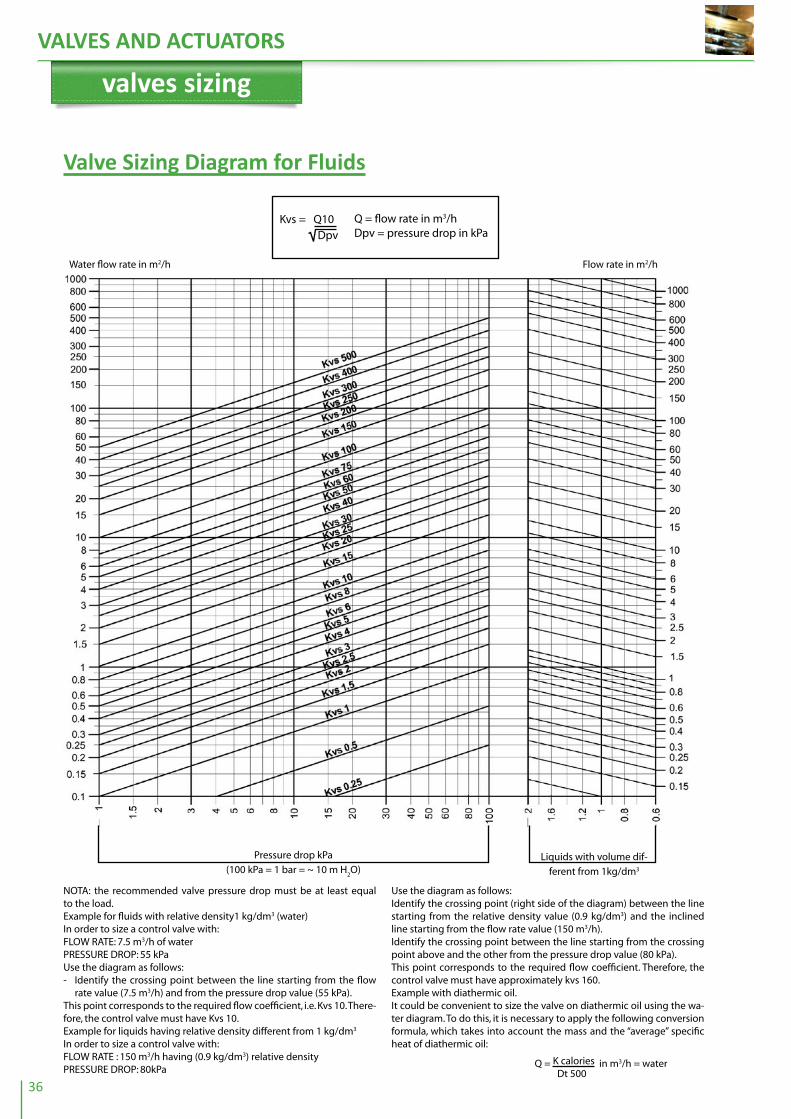
Valve Sizing Diagram for fluids
Kvs = Q10 Dpv
Q = flow rate in m3/hDpv = pressure drop in kPa
Water flow rate in m2/h Flow rate in m2/h
Pressure drop kPa
(100 kPa = 1 bar = ~ 10 m H2O)
Liquids with volume dif-
ferent from 1kg/dm3
NOTA: the recommended valve pressure drop must be at least equal to the load.Example for fluids with relative density1 kg/dm3 (water) In order to size a control valve with: FLOW RATE: 7.5 m3/h of waterPRESSURE DROP: 55 kPaUse the diagram as follows:- Identify the crossing point between the line starting from the flow
rate value (7.5 m3/h) and from the pressure drop value (55 kPa).This point corresponds to the required flow coefficient, i.e. Kvs 10. There-fore, the control valve must have Kvs 10. Example for liquids having relative density different from 1 kg/dm3
In order to size a control valve with:FLOW RATE : 150 m3/h having (0.9 kg/dm3) relative densityPRESSURE DROP: 80kPa
Use the diagram as follows:Identify the crossing point (right side of the diagram) between the line starting from the relative density value (0.9 kg/dm3) and the inclined line starting from the flow rate value (150 m3/h).Identify the crossing point between the line starting from the crossing point above and the other from the pressure drop value (80 kPa).This point corresponds to the required flow coefficient. Therefore, the control valve must have approximately kvs 160.Example with diathermic oil.It could be convenient to size the valve on diathermic oil using the wa-ter diagram. To do this, it is necessary to apply the following conversion formula, which takes into account the mass and the “average” specific heat of diathermic oil:
Q = K calories in m3/h = water Dt 500

VALVES AND ACTUATORS
37
Valve Sizing Diagram for Steam
Saturated steam flow rate kg/h Overheated steam flow rate kg/h
Q = flow rate m3/hDpv = valve leakagePu = absolute pressure downstream the valve (bar)
Kvs = Q 22.8 • Dpv • Pu
Press
ure d
rop
Critical p
ressure
drop
Overheating degree
NOTE: The recommended valve presssure drop is about 30% of the absolute supply pressure.
Example for saturated steam:FLOW RATE: 4700 Kg/h of saturated steamABSOLUTE PRESSURE UPSTREAM: 850 kPaPRESSURE DROP: 160 kPa
Use the diagram as follows:- Identify the crossing point between the line starting from absolute
pressure upstream the valve (850 kPa) and the inclined line corre-sponding to the pressure drop value (160 kPa).
- Identify the crossing point between the line starting from the cross-ing point above and the line from the flow rate value (4700 Kg/h).
This point corresponds to the required flow rate coefficient: Kvs 63.
Example for overheated steam:FLOW RATE: 140 Kg/h of overheated steamABSOLUTE PRESSURE UPSTREAM: 350 kPaTEMPERATURE: 209 °CPRESSURE DROP: 100 kPaCalculate the overheating degree of steam as follows:- On the left side of the diagram, read the temperature value corre-
sponding to 350 kPa (139 °C). The overheating degree is: 209 – 139 = 70 °CUse the diagram as follows:- Identify the crossing point “A” (right side of the diagram) between the
line starting from the overheating value (70 °C) and the inclined line corresponding to the flow rate value (140 Kg/h).
- Identify the crossing point “B” between the line starting from the val-ue of pressure upstream (350 kPa) and the inclined line correspond-ing to the value of pressure drop (100 kPa).
- Identify the crossing point between the line starting from the points “A” and “B”.
VALVES AND ACTUATORS
38
control valves sizingHow to Calculate Kvs
Flow coefficient Kvs is the flow rate of water in m3/h passing through a fully open valve at a 100 kPa pressure drop.
a) Liquids kvs= 10 x Q x r
Dp
Q = flow rate m3/h
Dp = pressure drop (kPa)
r = relative density (kg/dm3)
The Dp pressure drop should be determined as follows:
- Equal or higher than the Dp of the circuit under control, in case of variable flow ap-plications
- Equal or higher than the Dp of the supply circuit, in case of constant flow applications
b) Steam kvs = 100 x G x C
20.3 P2 x Dpv
G = flow rate (kg/h)
C = 1 + 0.0013 (t-ts)
t = steam temperature in working conditions
ts = saturated steam temperature at P2 pressure
P2 = pressure downstream (kPa)
Dpv = pressure drop (kPa)
Choose the valve with the Kvs closest to the calculated one.
Water Systems Two-way valve
For this application the pressure drop through the valve must be high, in order to have a good control flow characteristic and a properly working system.
1) The valve pressure drop must be 30 to 50% of the pressure upstream the valve.
2) The valve pressure drop must be equal to, or higher than the pressure drop of the coil or heat exchanger under control, in particular:
Temperature drop of heat exchanger Design of valve pressure drop
30 °C Equal to pressure drop of heat exchanger
20 °C Twice as pressure drop of heat exchanger
10 °C Three times as pressure drop of heat exchanger
Three- way mixing valveFor mixing valve a high pressure drop is not normally required even when used in pri-mary and secondary water circuits to control supply temperature to users.As a general rule, the valve must have a pressure drop similar to the one of the heat exchanger.
Three-way diverting valveThree-way diverting valves are used to control flow to heat exchanger and, therefore, the pressure drop through the valve. For proportional systems it must be high.
Note: When selecting pressure drop, you must not exceed the above-mentioned values because an undersized valve could produce:
- Noisy operation and vibration of the plug - Rapid wear of plug and seat due to high speed of the fluid through the valve.

VALVES AND ACTUATORS
39
Overheated Water SystemsFor this application the valves can be two- or three-way type.The valve pressure drop must be high, in order to have a good control flow characteristic and a properly working system.The principles and rules for correct sizing are the same as “WATER SYSTEMS”.
Steam SystemsFor low pressure steam systems (up to 2 bar), the pressure drop through the valve must be from 60 to 80 % of the pressure available upstream the valve.
Steam pressure upstream the valve Valve pressure drop
0.5 bar (50 kPa) 40 kPa
1.0 bar (100 kPa) 70 kPa
For high pressure steam systems (above 2 bar) the pressure drop through the valve must be from 30 to 40% of the pressure available upstream the valve.
Steam pressure upstream the valve Valve pressure drop
200 kPa 80 kPa
600 kPa 200 kPa
1,000 kPa 300 kPa
For on/off valves there are no particular rules to follow: pressure drop may be 10 to 20% of inlet pressure, but the valve is normally pipe sized.
Note: Do not size valves for high pressure steam with pressure drop higher than 50% of absolute pressure upstream: beyond this percentage thermodynamic problems could affect valve efficiency and life.
Diathermic Oil SystemsThe most commonly used valve type is three-way with linear characteristics, in order to ensure a constant flow to the boiler by constant speed.
Two-way valves can be used for several low-power users and wherever a balanced-plug valve is mounted between supply and return boiler.
The pressure drop of three-way valves must be at least equal to or higher than the one of the heat exchanger.
For a single user control, the valve must have a pressure drop from 30 to 50% of the system pressure drop.
For two-way valves, see also the “WATER SYSTEMS” section.

this page intentionally left blank

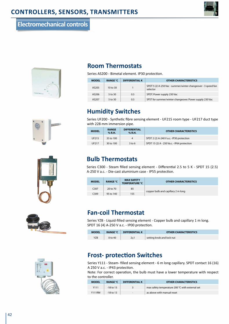
CONTROLLERS, SENSORS, TRANSMITTERS
42
Electromechanical controls
MoDEl ranGE °C DiFFErEntial K otHEr CHaraCtEriStiCS
AS205 10 to 30 1SPDT 5 (2) A-250 Vac - summer/winter changeover - 3 speed fan selector
AS206 5 to 30 0.5 SPDT. Power supply 230 Vac
AS207 5 to 30 0.5 SPST for summer/winter changeover. Power supply 230 Vac
Room ThermostatsSeries AS200 - Bimetal element. IP30 protection.
MoDElranGE % r.H.
DiFFErEntial % r.H.
otHEr CHaraCtEriStiCS
UF215 35 to 100 4 SPDT 2 (2) A-240 V a.c.- IP30 protection
UF217 30 to 100 3 to 6 SPDT 15 (2) A - 250 Va.c. - IP64 protection
Humidity SwitchesSeries UF200 - Synthetic fibre sensing element - UF215 room type - UF217 duct type with 228 mm immersion pipe.
MoDEl ranGE °CMaX SaFEtY
tEMPEratUrE °CotHEr CHaraCtEriStiCS
C307 20 to 70 85copper bulb and capillary 2 m long
C309 95 to 140 155
Bulb ThermostatsSeries C300 - Steam filled sensing element - Differential 2.5 to 5 K - SPDT 15 (2.5) A-250 V a.c. - Die-cast aluminium case - IP55 protection.
MoDEl ranGE °C DiFFErEntial K otHEr CHaraCtEriStiCS
YZB 0 to 40 2+1 setting knob and lock nut
fan-coil ThermostatSeries YZB - Liquid-filled sensing element - Copper bulb and capillary 1 m long.SPDT 16 (4) A-250 V a.c. - IP00 protection.
MoDEl ranGE °C DiFFErEntial K otHEr CHaraCtEriStiCS
Y111 -18 to 13 3 max safety temperature 200 °C with external set
Y111RM -18 to 13 - as above with manual reset
frost- protection switchesSeries Y111 - Steam- filled sensing element - 6 m long capillary. SPDT contact 16 (16) A 250 V a.c. - IP43 protection.Note: For correct operation, the bulb must have a lower temperature with respect to the controller.

43
CONTROLLERS, SENSORS, TRANSMITTERS
MoDEl ranGE °C DiFFErEntial K otHEr CHaraCtEriStiCS
YTC3 0 to 90 6+2 copper well gas 3/4” - 100 mm long
Immersion ThermostatsSeries YTC3 - Liquid-filled sensing element - SPDT 16 (4) A-250 V a.c. - IP43 protection.
MoDElranGE
kPaDiFFErEntial
kPaMaX SaFEtY
PrESSUrE kPaotHEr CHaraCtEriStiCS
B301 10 to 200 7 to 30 600
copper alloy bellowsB302 100 to 600 15 to 120 900
B303 200 to 1400 60 to 400 2200
B304 500 to 3000 80 to 400 3800
B301X 10 to 200 7 to 30 600
AISI 316 stainless steel bellowsB302X 100 to 600 15 to 120 900
B303X 200 to 1400 60 to 400 2200
B304X 500 to 3000 80 to 400 3800
Pressure SwitchesSeries B300 - Metal bellows sensing element - SPDT 15 (2.5) A-250 V a.c. - Die-cast aluminium case - IP55 protection.
MoDElranGE
PaMaX SaFEtY
PrESSUrE kPaotHEr CHaraCtEriStiCS
BD297 30 to 500 50- connections Ø 5 mm for PVC pipe - with 2m tube and bracket for wall mounting
differential Pressure switchesSeries BD200 - Differential pressure switch for signalling dirty air filter - Silver con-tacts - Membrane sensing element - IP54 protection.
MoDEl ranGE otHEr CHaraCtEriStiCS
Y106 1 to 85 m3/h for liquids - 1" screwed connections for pipes Ø 1" to 8"
Y105 1 to 10 m/ s for air - with paddle 175 x 80 mm
flow SwitchesSeries Y100 - Paddle type - Protection degree: Y102 IP55, Y105 IP65. SPDT contact 15 (8) A-230 V a.c.
MoDElMaX WorKinG PrESSUrE kPa
DiFFErEntial mm
MaX WorKinG tEMPEratUrE °C
otHEr CHaraCtEriStiCS
FG601 1600 15 to 60 200 cast-iron body - connections 20 mm
FG603 3000 25 to 60 230 stainless steel body connections 20 mm
Level ControllersSeries FG600 - Float-type - AISI 304 stainless steel - Flanged connections - SPDT 10 (1) A-24 V a.c. - Industrial water-proof case - IP55 protection.

CONTROLLERS, SENSORS, TRANSMITTERS
44
MoDEl ranGE °CProPortional-
BanD KMaX SaFEtY
tEMP.°CotHEr CHaraCtEriStiCS
C357 20 to 70 3 to 10 85 copper bulb and capillary 2 m long
Bulb ThermostatsSeries C350 - Steam filled sensing element - 165 Ohm potentiometer - Die-cast alu-minium case - IP55 protection.
MoDElranGE
kPaProPortional
BanD kPaMaX SaFEtY
PrESSUrE kPaotHEr CHaraCtEriStiCS
B353 200 to 1400 150 to 900 2200copper alloy bellows
B354 500 to 3000 120 to 900 3800
B353X 200 to 1400 150 to 900 2200AISI 316 stainless steel bellows
B354X 500 to 3000 120 to 900 3800
Pressure SwitchesSeries B350 - Metal bellows sensing element - 165 Ohm potentiometer - Die-cast aluminium case - IP55 protection.
MoDElMaX WorKinG-PrESSUrE kPa
ProPortional BanD mm
MaX WorKinG tEMPEratUrE °C
otHEr CHaraCtEriStiCS
FG651 1600 60 200 cast-iron body-connections 20 mm
FG653 3000 60 230 cast-steel body-connections 20 mm
Level ControllersSeries FG650 - AISI 304 stainless steel float - Flanged connections - 165 Ohm poten-tiometer - Industrial water-proof case.
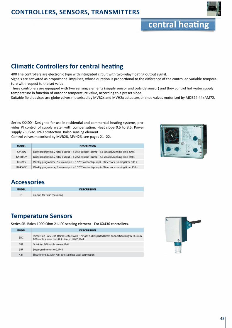
45
CONTROLLERS, SENSORS, TRANSMITTERS
Climatic Controllers for central heating400 line controllers are electronic type with integrated circuit with two-relay floating output signal.Signals are activated as proportional impulses, whose duration is proportional to the difference of the controlled variable tempera-ture with respect to the set value.These controllers are equipped with two sensing elements (supply sensor and outside sensor) and they control hot water supply temperature in function of outdoor temperature value, according to a preset slope. Suitable field devices are globe valves motorised by MVB2x and MVH2x actuators or shoe valves motorised by MDB24-44+AM72.
central heating
MoDEl DESCriPtion
KX436G Daily programme, 2 relay output + 1 SPST contact (pump) - SB sensors, running time 300 s.
KX436GV Daily programme, 2 relay output + 1 SPST contact (pump) - SB sensors, running time 150 s.
KX436S Weekly programme, 2 relay output + 1 SPST contact (pump) - SB sensors, running time 300 s.
KX436SV Weekly programme, 2 relay output + 1 SPST contact (pump) - SB sensors, running time 150 s.
Series KX400 - Designed for use in residential and commercial heating systems, pro-vides PI control of supply water with compensation. Heat slope 0.5 to 3.5. Power supply 230 Vac. IP40 protection. Balco sensing element.Control valves motorised by MVB28, MVH26, see pages 21 -22.
MoDEl DESCriPtion
F1 Bracket for flush mounting
Accessories
MoDEl DESCriPtion
SBCImmersion - AISI 304 stainless steel well, 1/2” gas nickel-plated brass connection length 113 mm, PG9 cable sleeve, max fluid temp.: 140°C, IP44
SBE Outside - PG9 cable sleeve, IP44
SBF Strap-on (immersion), IP44
421 Sheath for SBC with AISI 304 stainless steel connection
Temperature Sensors Series SB. Balco 1000 Ohm 21.1°C sensing element - For KX436 controllers.

CONTROLLERS, SENSORS, TRANSMITTERS
46
MoDEl ranGE °C DiFFErEntial otHEr CHaraCtEriStiCS
AX236 10 to 30hysteresis
0.5 Kon/off, 3 fan speed control
4200-588 Fan coil controller, 2-pipe/4-pipe, SPDT contact, 3 speed fan control, S/W changeover, on/off switch
4200-662 Fan coil controller, 4-pipe, SPDT contact, 3 speed fan control, S/W changeover, on/off switch
4200-953 Fan coil controller with lCD display, 2-pipe, SPDT contact, 3 speed fan control, on/off switch
4200-577 Fan coil controller with lCD display, 4-pipe, SPDT contact, 3 speed fan control, on/off switch
Room ThermostatsThermistor sensing element - Supply 230 V ac.
MoDEl DESCriPtion
AXCU22/W Controller for 2/4-pipe fan coils
AXCU22/WMB Controller for 2/4-pipe fan coils with ModBus connectivity
Electronic Controllers for fCusAXC series - Periodic ventilation, valve protection, set point limit, led indication (He-ating/Cooling/On), hot start (timer), periodic valve opening, Economy switch (on re-quest), 3 fan speed selector, water sensor input, window contact input, automatic changeover, electric heater. IP30 protection, power supply 230Vac, 50/60Hz. Suitable to remote monitoring from GT TouchScreen, page 48.
MoDEl DESCriPtion
SNTC-L Temperature sensor, ABS 7x25mm-cap, PVC cable, range - 30..80°C, cable length 1.5 m.
SNTC-SLTemperature sensor, AISI 304 6x40 mm-steel cap, silicone cable, range - 30..105 °C, cable length 1.5 m.
Water and Air Sensors for AXC ControllersInput ST2 can be connected to a NTC sensor (additional to the internal sensor: by a dip switch it is possible to choose which one to use) installed on the return air flow. Input ST3 can be connected to a NTC sensor to measure the water temperature (to be mounted downstream the valve). This sensor is used to acknowledge operation.
MoDEl DESCriPtion
AXCU/BA Bus Adapter for AXCU22/WMB
Accessories for ModBus version connectivity
controllers for fCus
Room ControllersSeries AX500 - Built-in NTC sensing element - Power supply 24 Vac - IP30 protection - Optional external temperature sensor STR73, see page 49.
MoDEl ranGE °CProPortional
BanD KotHEr CHaraCtEriStiCS
AX526 5 to 30 1.5 2 outputs 0 to 10 Vdc
AX527 5 to 30 3 As AX526 with on/off switch and 3 fan speed control
AX536 5 to 30 1.52 outputs 0 to 10 Vdc with on/off electric heater output and LCD display
AX537 5 to 30 1.5 As AX536 with on/off switch and 3 fan speed control
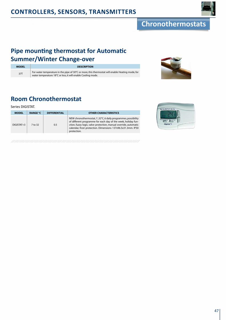
47
CONTROLLERS, SENSORS, TRANSMITTERS
MoDEl ranGE °C DiFFErEntial otHEr CHaraCtEriStiCS
DIGISTAT+3 7 to 32 0.5
NEW chronothermostat, 7..32°C, 6 daily programmes, possibility of different programme for each day of the week, holiday fun-ction, fuzzy logic, valve protection, manual override, automatic calendar, frost protection. Dimensions 137x96.5x31.3mm. IP30 protection.
Room ChronothermostatSeries DIGISTAT.
MoDEl DESCriPtion
37TFor water temperature in the pipe of 30°C or more, this thermostat will enable Heating mode, for water temperature 18°C or less, it will enable Cooling mode.
Pipe mounting thermostat for Automatic Summer/Winter Change-over
Chronothermostats

CONTROLLERS, SENSORS, TRANSMITTERS
48
The new DG8000 series controllers are particularly suitable for temperature control in hotel rooms, hospitals, offices, in applica-tions such as fan coils or small AHU. The controllers can operate stand-alone or can be supervised remotely through ModBus pro-tocol (up to 250 devices).
1) Other frames of different colours or materials are available. Please contact our Sales Support.
Digital fan Coil ControllersSeries DG8000 - Two controller types (floating or on/off valve con-trol) - Fan speed control - 2- or 4-pipe management - Interchange-able user display frames (1) - Power supply 230 Vac - Supervision through ModBus protocol. Badge contact, window contact, alarm, occupancy control.Suitable to remote monitoring from GT TouchScreen, page 56.
MoDEl DESCriPtion
DG8000 Controller for floating valve control
DG8001 Controller for on/off valve control
DG8011 User display with white standard plate1)
DG8022 Return sensor (range 1-55 °C), fixed length 1.5 m
Configuration toolSoftware tool for DG8000 controllers. The programme allows configuring through ModBus protocol (using a opto-isolated RS232/RS485 or USB/RS485 converter) the operation modes and setting values different from default ones. This tool is particularly useful during plant and supervision start-up.
Room controllers
- Set the fan speed (automatic or manual)- Stop the fan when the set value is reached- Enable switch-off by window contact- Select winter or summer operation (only for two-pipe applications)
- Activate automatically control by inserting the badge- Activate electric loads- Detect an alarm signal.

49
CONTROLLERS, SENSORS, TRANSMITTERS
PID controllers
MoDEl oUtPUt inPUt PoWEr SUPPlY Vac
CTY231 2 relay+1 alarm PTC 230
CTY232 2 relay+1 alarm Pt100 and 4-20mA 230
CTY241 2 relay+1 alarm PTC 24
CTY242 2 relay+1 alarm Pt100 and 4-20mA 24
CTY541 0 to 10 V+1 relay+1 alarm PTC 24/230
CTY542 0 to 10 V+1 relay+1 alarm Pt100 and 4-20mA 24/230
Temperature ControllersSeries CTY - DDC controllers with analogue or digital output and PD or PID action. Dimensions 72x72x102mm, panel mounting (cut-out 67x67mm). SPTC sensors see page 58. More features: off-set, copy card, password, alarms, duty-cycle. When pressure or humidity transmitters are connected (4-20 mA) CTY will become pressure or humidity controllers (0-100% range). Available units: °C, °F, bar, %RH, Pa, psi.
MoDEl ranGE °CProPortional
BanD KintEGration
tiME tn (s) DEriVatiVE
tiME tDMoUntinG
CX528 -10 to 120°C 2 to 40 16 to 600 1/4 Tn wall or flush
Series CX500 - Proportional - Integral - Derivative (PID), adjustable on field into Pro-portional - Direct/reverse action - Power supply directly from MVB-MDL-MVF-MVH actuator - Sensing element: see SB sensors, page 58 - IP55 protection.
1) Max load controlled by analogue output: 0-1V = 20mA with 50 Ohm min. load resistance; 0-5V = 20mA with 250 Ohm min. load resistance; 0-10V = 20mA with 500 Ohm min. load resistance; 0-20 mA or 4-20 mA = 350 Ohm.
MoDElPoWEr SUPPlY
VacoUtPUtS inPUt
TX542 24/2301 alarm relay output
1 configurable analogue output1) Pt100
Temperature Controllers for Industrial Applica-tions, Heat exchangers, etc.Series TX500 - P, PD and Proportional - Integral - Derivative action (PID) - Power sup-ply 230 or 24 Vac - Configurable as heating or cooling loop - Supervision by ModBus protocol - Sensing element: see SP-TP below or SPTX-U - Flush mounting with 67x67 mm panel cut-out - IP54 protection.
Copy card
Temperature ControllersSeries RX500 - Direct/reverse action - Sensing elements: see SB sensors at page 58. Power supply from MVB, MVF, MVH, MDL actuators - IP40 protection.
MoDEl ranGE °CProPortional
BanD KSEt Point otHEr CHaraCtEriStiCS
RX513 0÷45 3÷24external wall mounting
RX515 -10÷80 3÷24

CONTROLLERS, SENSORS, TRANSMITTERS
50
MoDEl DESCriPtion
SPTX-UUniversal sensor, Pt100 sensing element, cable length 3 m, sensor material AISI316 steel, max fluid temperature: 350 °C
SPCImmersion, AISI 304 well, 1/2” gas connection, conduit opening Ø 10 mm, 113 mm long, max fluid temperature: 150 °C, IP44 protection
TPCImmersion, 1/2”gas connection, AISI 304 well, conduit opening Ø 10 mm 200 mm long, max fluid temperature: 500 °C - IP55 protection
421 Option for SPC: AISI 304 stainless steel sheath and connection
SensorsTemperature sensors for TX and CTYxx2 with Platinum (100 Ohm at 0°C) sensing ele-ment.
MoDEl DESCriPtion
ARAD9672Hole adapter (96x96 to 72x 72mm) for front panel mounting to replace analogue TX and RX series having 96x96 mm drilling templalte
4200-1322 COPY CARD for data storage and upload/download of parameter settings on CTY and TX
Accessories for CTy-TX

51
CONTROLLERS, SENSORS, TRANSMITTERS
Configurable controllers
DDC Temperature ControllersOmnia series - PTC sensing element - Power supply 230 Vac or 24 Vac - Data exchange through LinkBus - ModBus capability - IP30 protection - Dimensions 70X85X61 mm. For data reading through Touchscreen see page 56.
MoDEl DESCriPtion
W500TDigital temperature controller. P, P+I control, limit and compensation fun-ctions. 3 analogue inputs+ 2 digital inputs, 2 analogue 0÷10 Vdc outputs + 2 relay outputs. 3 ½-digit display. DIN rail mounting, 230 Vac power supply
W500T4 As above with 24 Vac power supply
W500TMB As W500T with RTC clock and ModBus connectivity, 230 Vac power supply
W500TMB4 As W500TMB with 24 Vac power supply
W501TMB As W500TMB with application-specific default values and 3-position output
W500T2 As W500T but with two independent control loops
W500T2MB As W500TMB but with two independent control loops
ddC Controllers for temperature, Humidity and Pressure Omnia series - PTC sensing element - Power supply 230 Vac or 24 Vac - Data exchange through LinkBus - ModBus capability - IP30 protection - Dimensions 70X85X61 mm.For data reading through Touchscreen see page 56.
MoDEl DESCriPtion
W500HDigital temperature and humidity controller. P, P+I control, limit and compensation functions 3 analogue inputs+ 2 digital inputs, 2 analogue 0÷10 Vdc outputs and 2 relay outputs. 3 ½-digit display. DIN rail mounting, 230 Vac power supply
W500H4 As above with 24 Vac power supply
W500HMB As W500H with RTC clock and ModBus connectivity, 230 Vac power supply
W500HMB4 As W500HMB with 24 Vac power supply
Programming ToolProgramming tool for W500T, W500TMB, W500H, W500HMB controllers.You can set all parameters from your PC or Laptop by simply connecting one or more controllers via either a RS232/485 converter or a USB/ RS485 opto-isolated converter.All configurations can be saved on your PC and downloaded onto other controllers.
Temperature Sensors PTC sensing element for Omnia controllers (see also page 58)
MoDEl DESCriPtion
SPTC-A / S23x Room sensor (dimensions 86x86x31 mm) - IP30
SPTC-A5 / S22x Room sensor with set point adjustment (dimensions 86x86x31 mm) - IP30
SPTC-A6 / S21x Room sensor with 10-30 °C scale (dimensions 86x86x31 mm) - IP30
SPTC-C Immersion sensor cable type (provide a well), 1.5 m silicone cable
SPTC-CR Immersion sensor with case and stick enclosed - supplied with brass pocket
SPTC-D Duct sensor cable type (provide a well), 1.5 m silicone cable
SPTC-E Outside sensor - IP44
SPTC-F Strap-on pipe sensor - IP44
SPTC-V As SPTC-D but with case and stick enclosed - IP44
Accessories for Omnia ControllersMoDEl DESCriPtion
LIBO-USB USB-RS485 optically isolated converter
RM500 Remote positioner for Omnia controllers, working range 5÷35 °C
Omnia®

CONTROLLERS, SENSORS, TRANSMITTERS
52
LIBERTy SeriesAlready programmed for specific HVAC applications. No software needed. Same hardware of OmniaPRO controllers.Inputs: 6 digital + 5 analogue (3 passive NTC + 2 NTC or V or mA)Outputs: 5 digital + 3 analogue (0-10Vdc / 4(0)-20mA)I/O additional modules available with 11 inputs + 8 outputsIn-built or remote display. 12-24 Vca power supply. DIN rail mounting.Models with “S” (with RS485) can be remotely moni-tored by GT Touch Screens. Number of controllers that can be connected to one GT touch screen: from 10 to 40 controllers, depending on the architecture.
Model-nuMBeR DESCRIPTION
W551C controller without display
Fresh Air AHUW551C-S controller without display with RS485
W551C-D controller with display
W551C-DS controller with display and RS485
W552C controller without display Constant air volume AHU with heat recovery
W552C-S controller without display with RS485
W552C-D controller with display
W552C-DS controller with display and RS485
W553C controller without displayHeat pump; Pro-portional humidi-fication
W553C-S controller without display with RS485
W553C-D controller with display
W553C-DS controller with display and RS485
W554C controller without display
for swimming pools
W554C-S controller without display with RS485
W554C-D controller with display
W554C-DS controller with display and RS485
W560-EXP additional I/Os module (11 Inputs + 8 Outputs)
W560-RT remote display, flush mountingLiberty
Liberty

53
CONTROLLERS, SENSORS, TRANSMITTERS
Programmable controller for small HVAC installations.Inputs: 6 digital + 5 analogue (3 passive NTC + 2 NTC or V or mA)Outputs: 5 digital + 3 analogue (0-10Vdc / 4(0)-20mA)I/O additional modules available with 11 inputs + 8 outputsIn-built or remote display. 12-24 Vca or 100-240Vac power supply.ModBus connectivity RS485 and RTC (option).Models with “S” (with RS485) can be remotely moni-tored by GT Touch Screens. Number of controllers that can be connected to one GT touch screen: from 10 to 40 controllers, depending on the architecture.Examples of application: AHUs with heating/cooling/humidity control, frost protection, compensation, op-timization, free cooling, electric heater, heat pump. Central heating, hot water service, boiliers and chillers sequencing and more.
Programmable controllers
Model-nuMBeR DESCRIPTION
WPRO-561 controller without display
WPRO-561S controller without display , RS485
WPRO-562 controller without display , 2 triacs
WPRO-562S controller without display , 2 triacs , RS485
WPRO-561D controller with display
WPRO-561DS controller with display , RS485
WPRO-562D controller with display , 2 triacs
WPRO-562DS controller with display , 2 triacs , RS485
W560-EXP additional I/Os module (11 Inputs + 8 Outputs)
W560-RT remote display, flush mounting
WPRO-521 controller without display
WPRO-521S controller without display , RS485
WPRO-521D controller with display
WPRO-521DS controller with display , RS485
W521-EXP additional I/Os module (11 Inputs + 8 Outputs)100-
240V
ac

CONTROLLERS, SENSORS, TRANSMITTERS
54
W560 SeriesConfigurable controller with display for underfloor heating & cooling systems 6 digital inputs + 5 analogue inputs (3 passive NTC + 2 NTC or V or mA)5 digital outputs + 3 analogue outputs + 1 analogue output PWM + 2 triac outputs12-24 Vca power supply ModBus connectivity RS485 (option).
underfloor heating/cooling
Model-number description
W562D controller with 3 pos. control
W562DS controller with 3 pos. control with RS485
W562DM controller with modulating control
W562DSMcontroller with modulating control with RS485
W560-EXPadditional I/Os module (11 Inputs + 8 Out-puts)
W560-RT remote display, flush mounting
STA60L room temperature sensor with display
STA61Lroom temperature + humidity sensor with display
W562 controller will control the 3way mixing valve (0-10V) accord-ing to the set-point temperature from the room sensor. Based on the input from the room thermostats, W562 will abilitate the elec-tro-thermal actuators on the manifold. In case of an alarm, thermal actuators will be closed. External temperature and water return temperature will compensate the set-point temperature for energy saving purposes. Floor temperature sensor is used as a limit. W562 provides deu-midification control to avoid condensation. More features: Summer/Winter change-over; remote On/Off activation; Economy mode.
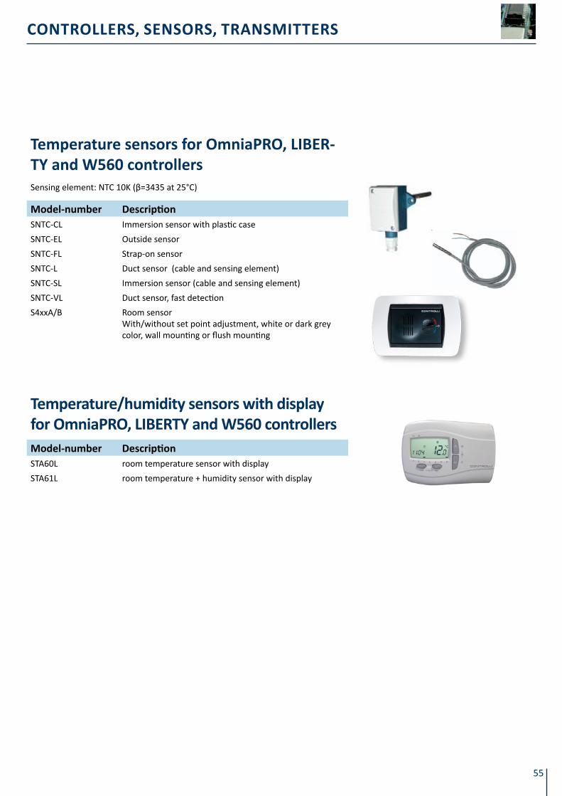
55
CONTROLLERS, SENSORS, TRANSMITTERS
temperature sensors for omniaPRo, lIBeR-Ty and W560 controllersSensing element: NTC 10K (β=3435 at 25°C)
Model-number descriptionSNTC-CL Immersion sensor with plastic case
SNTC-EL Outside sensor
SNTC-FL Strap-on sensor
SNTC-L Duct sensor (cable and sensing element)
SNTC-SL Immersion sensor (cable and sensing element)
SNTC-VL Duct sensor, fast detection
S4xxA/B Room sensor With/without set point adjustment, white or dark grey color, wall mounting or flush mounting
Temperature/humidity sensors with display for omniaPRo, lIBeRtY and W560 controllersModel-number descriptionSTA60L room temperature sensor with display
STA61L room temperature + humidity sensor with display

CONTROLLERS, SENSORS, TRANSMITTERS
56
GT series – Graphic terminals suitable to the following Controlli devices: W500TMB/W500HMB digital controllersAXCU22/WMB fan-coil controllersDG8000 room controllersOmniaPro controllers & Multinet controllersMonochrome and colour touchscreens available in 3 different sizes: 5.7” – 7.5” – 10.4”ModBus protocol, Ethernet port.Web server capabilities: a plant can be monitored remotely via Internet explorer browser.
Html pages browser. Automatic email sending upon specific events.
Hight speed with RISC 64 bit processor40 fonts for various foreingh languages supported.Library with 4000 editable objects.USB flash drive for applications downloadingCompact flash card (1Gb) for storing of all applications/instructions files/images/logs etc..Application memory capacity from 16MB to 32MB.Available with 2 independent serial ports RS485.different controllers – e.g. W500 and AXCu22/WMB – can be simultanely connected to a single touch screen.Alarms and log management. 220/24Vcc transformer included.
Remote monitoring
MoDEl DiMEnSionS SCrEEn SiZE SCrEEn tYPErESolUtion
PiXElEtHErnEt
Port
GT2110
167.5x135 5,7”
blue
320x240
NO
GT2130 grey YES
GT2220 4096 colours NO
GT2330 65536 colours YES
GT4230 215x170 7.5”4096 colours 640x480 YES
GT5230 313x239 10.4”
GT2110xx1) GT2110 with preset application
GT2130xx1) GT2130 with preset application
GT2220xx1) GT2220 with preset application
GT2330xx1) GT2330 with preset application
GT4230xx1) GT4230 with preset application
GT5230xx1) GT5230 with preset application
GTDB9CAV RS232 SUB-D 9 cable
GTRJ45CAV RS485 cable
1) XX=AA max 40 AXCU XX=WW max 20 W500TMB/W500HMB XX=DD max 40 DG8000 XX=AW max 40 AXCU + 8 W500TMB/W500HMB, XX=DW max 40 DG8000 + 8 W500TMB/W500HMB

57
CONTROLLERS, SENSORS, TRANSMITTERS

CONTROLLERS, SENSORS, TRANSMITTERS
58
Temperature Sensors
Temperature Sensors Balco 1000 Ohm at 21.1 °C sensing element - for KX436 and CX528 controllers.
MoDEl DESCriPtion
SBA / S13x Room sensor - IP30
SBA55 / S14x Room sensor with set-point adjustment potentiometer 5 to 35°C - IP30 protection
SBCImmersion - AISI 304 stainless steel well- 1/2” gas nickel-plated brass connection length 113 mm - PG9 cable sleeve - max fluid temperature: 140 °C - IP44 - supplied with brass pocket
SBDDuct - with mounting flange - 7.5 mm - length 300 mm - PG9 cable sleeve, max fluid temperature: 95 °C - IP44
SBE Outside - PG9 cable sleeve - IP44
SBF Strap-on ( immersion) - IP44
SBVAs SBD but with uncovered fast-detecting sensing element - length 315 mm, max fluid tempera-ture: 65 °C - IP44not suitable for applications with possible condensation
421 Well for SBC and SPTC-C with AISI 304 stainless steel connection
Temperature Sensors PTC 1K (SPTC) and PT100 (SPTX-U only) sensing element for Omnia and CTY-TX controllers.
MoDEl DESCriPtion
SPTC-A / S23x Room sensor for Omnia controllers - IP30
SPTC-A5 / S22x Room sensor for Omnia with set point adjustment - IP30
SPTC-A6 / S21x Room sensor for Omnia with 10-30 °C degree scale - IP30
SPTC-C Immersion sensor for CTYxx1 and Omnia cable type, 1.5 m silicone cable
SPTC-CRImmersion sensor for CTYxx1 and Omnia with case and stick enclosed - supplied with brass po-cket
SPTC-D Duct sensor for CTYxx1 and Omnia, cable type, 1.5 m silicone cable
SPTC-E Outside sensor for Omnia with PG9 cable sleeve - IP44
SPTC-F Strap-on pipe sensor for Omnia - IP44
SPTC-VAs SPTC-D but with case and stick enclosed for Omnia and CTYxx1 - length 315 mm - max tem-perature 65 °C - IP44not suitable for applications with possible condensation
SPTX-U Universal sensor for CTYxx2, PT100 sensing element, cable type, 3 m cable
Temperature SensorsNTC sensing element : STA/STR, 5 K Ohm at 25°C, STR72 10 Kohm at 25 °C, STR73 33 Kohm at 25°C - Application range 0 to 50 °C.
MoDEl DESCriPtion
STA71 / S33x Room sensor with set point adjustment 5 to 35°C for NR7000 - IP30
STA75S / S32x Room sensor with set point adjustment 5 to 35°C 3K for NR7000 - IP30
STA80S / S34x Room sensor with set point adjustment 3 K - on/off and fan speed selector for NR7000 - IP30
STR71 Return air sensor with mounting kit for terminal unit for NR7000 - IP30
STR72 Return air or pipe-contact sensor without mounting kit for RA735 - IP30
STR73 Return air or pipe-contact sensor without mounting kit for AX526/527/536/537 - IP30
Part-numbers in red color (new models) available from august 2012.
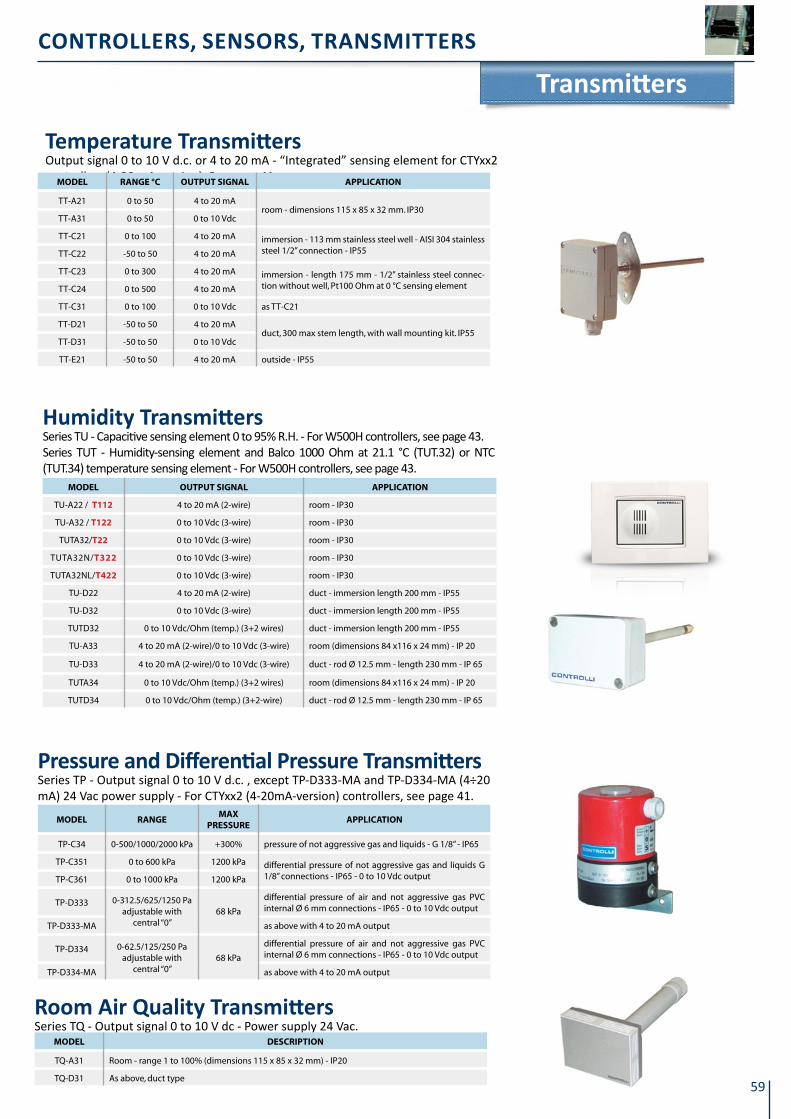
59
CONTROLLERS, SENSORS, TRANSMITTERS
transmitters
temperature transmittersOutput signal 0 to 10 V d.c. or 4 to 20 mA - “Integrated” sensing element for CTYxx2 controllers (4-20 mA-version). See page 41.MoDEl ranGE °C oUtPUt SiGnal aPPliCation
TT-A21 0 to 50 4 to 20 mAroom - dimensions 115 x 85 x 32 mm. IP30
TT-A31 0 to 50 0 to 10 Vdc
TT-C21 0 to 100 4 to 20 mA immersion - 113 mm stainless steel well - AISI 304 stainless steel 1/2” connection - IP55 TT-C22 -50 to 50 4 to 20 mA
TT-C23 0 to 300 4 to 20 mA immersion - length 175 mm - 1/2” stainless steel connec-tion without well, Pt100 Ohm at 0 °C sensing element TT-C24 0 to 500 4 to 20 mA
TT-C31 0 to 100 0 to 10 Vdc as TT-C21
TT-D21 -50 to 50 4 to 20 mAduct, 300 max stem length, with wall mounting kit. IP55
TT-D31 -50 to 50 0 to 10 Vdc
TT-E21 -50 to 50 4 to 20 mA outside - IP55
Humidity transmittersSeries TU - Capacitive sensing eIement 0 to 95% R.H. - For W500H controlIers, see page 43. Series TUT - Humidity-sensing element and Balco 1000 Ohm at 21.1 °C (TUT.32) or NTC (TUT.34) temperature sensing element - For W500H controllers, see page 43.
MoDEl oUtPUt SiGnal aPPliCation
TU-A22 / t112 4 to 20 mA (2-wire) room - IP30
TU-A32 / t122 0 to 10 Vdc (3-wire) room - IP30
TUTA32/t22 0 to 10 Vdc (3-wire) room - IP30
TUTA32N/t322 0 to 10 Vdc (3-wire) room - IP30
TUTA32NL/t422 0 to 10 Vdc (3-wire) room - IP30
TU-D22 4 to 20 mA (2-wire) duct - immersion length 200 mm - IP55
TU-D32 0 to 10 Vdc (3-wire) duct - immersion length 200 mm - IP55
TUTD32 0 to 10 Vdc/Ohm (temp.) (3+2 wires) duct - immersion length 200 mm - IP55
TU-A33 4 to 20 mA (2-wire)/0 to 10 Vdc (3-wire) room (dimensions 84 x116 x 24 mm) - IP 20
TU-D33 4 to 20 mA (2-wire)/0 to 10 Vdc (3-wire) duct - rod Ø 12.5 mm - length 230 mm - IP 65
TUTA34 0 to 10 Vdc/Ohm (temp.) (3+2 wires) room (dimensions 84 x116 x 24 mm) - IP 20
TUTD34 0 to 10 Vdc/Ohm (temp.) (3+2-wire) duct - rod Ø 12.5 mm - length 230 mm - IP 65
Pressure and differential Pressure transmittersSeries TP - Output signal 0 to 10 V d.c. , except TP-D333-MA and TP-D334-MA (4÷20 mA) 24 Vac power supply - For CTYxx2 (4-20mA-version) controllers, see page 41.
MoDEl ranGEMaX
PrESSUrEaPPliCation
TP-C34 0-500/1000/2000 kPa +300% pressure of not aggressive gas and liquids - G 1/8” - IP65
TP-C351 0 to 600 kPa 1200 kPa differential pressure of not aggressive gas and liquids G 1/8” connections - IP65 - 0 to 10 Vdc outputTP-C361 0 to 1000 kPa 1200 kPa
TP-D333 0-312.5/625/1250 Paadjustable with
central “0”68 kPa
differential pressure of air and not aggressive gas PVC internal Ø 6 mm connections - IP65 - 0 to 10 Vdc output
TP-D333-MA as above with 4 to 20 mA output
TP-D334 0-62.5/125/250 Paadjustable with
central “0”68 kPa
differential pressure of air and not aggressive gas PVC internal Ø 6 mm connections - IP65 - 0 to 10 Vdc output
TP-D334-MA as above with 4 to 20 mA output
Room Air Quality transmittersSeries TQ - Output signal 0 to 10 V dc - Power supply 24 Vac.
MoDEl DESCriPtion
TQ-A31 Room - range 1 to 100% (dimensions 115 x 85 x 32 mm) - IP20
TQ-D31 As above, duct type
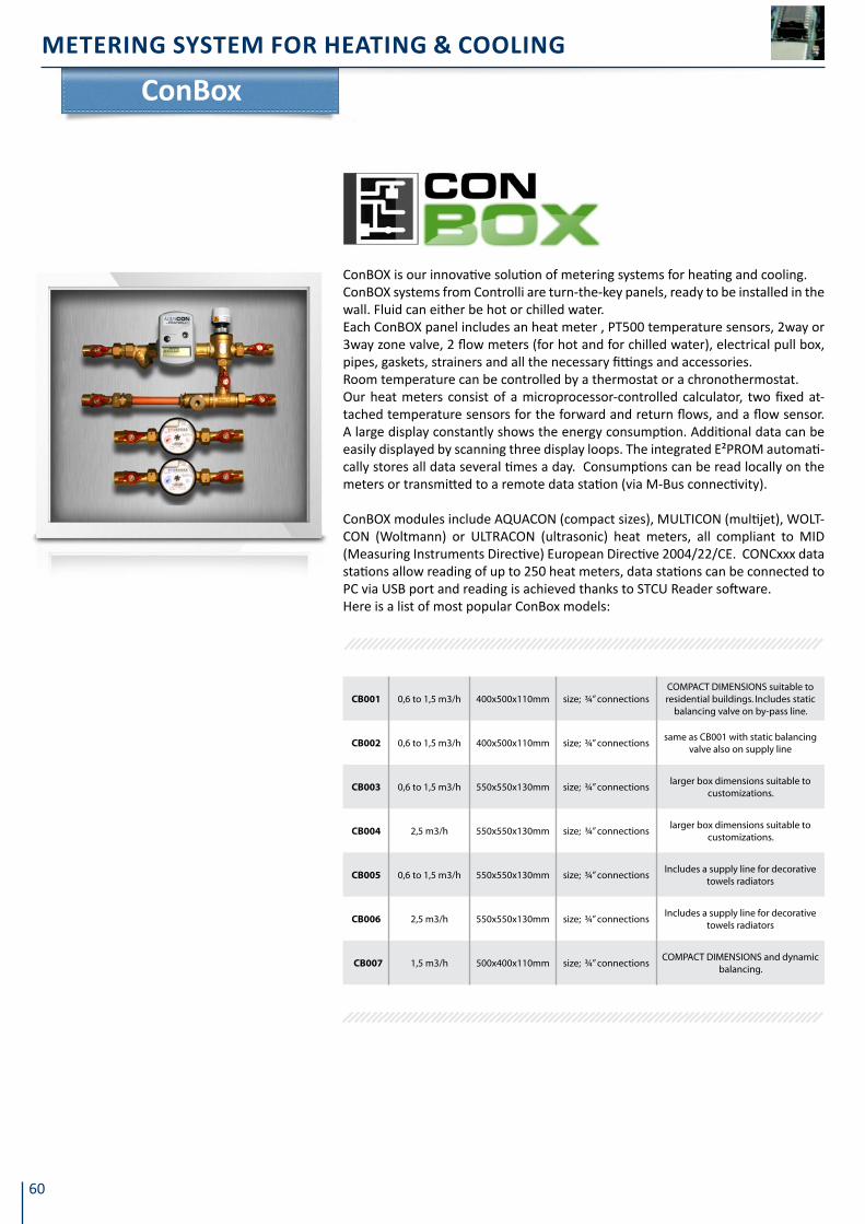
60
METERING SySTEM fOR HEATING & COOLING
ConBOX is our innovative solution of metering systems for heating and cooling. ConBOX systems from Controlli are turn-the-key panels, ready to be installed in the wall. Fluid can either be hot or chilled water.Each ConBOX panel includes an heat meter , PT500 temperature sensors, 2way or 3way zone valve, 2 flow meters (for hot and for chilled water), electrical pull box, pipes, gaskets, strainers and all the necessary fittings and accessories.Room temperature can be controlled by a thermostat or a chronothermostat.Our heat meters consist of a microprocessor-controlled calculator, two fixed at-tached temperature sensors for the forward and return flows, and a flow sensor. A large display constantly shows the energy consumption. Additional data can be easily displayed by scanning three display loops. The integrated E²PROM automati-cally stores all data several times a day. Consumptions can be read locally on the meters or transmitted to a remote data station (via M-Bus connectivity).
ConBOX modules include AQUACON (compact sizes), MULTICON (multijet), WOLT-CON (Woltmann) or ULTRACON (ultrasonic) heat meters, all compliant to MID (Measuring Instruments Directive) European Directive 2004/22/CE. CONCxxx data stations allow reading of up to 250 heat meters, data stations can be connected to PC via USB port and reading is achieved thanks to STCU Reader software.Here is a list of most popular ConBox models:
ConBox
CB001 0,6 to 1,5 m3/h 400x500x110mm size; ¾” connectionsCOMPACT DIMENSIONS suitable to residential buildings. Includes static
balancing valve on by-pass line.
CB002 0,6 to 1,5 m3/h 400x500x110mm size; ¾” connectionssame as CB001 with static balancing
valve also on supply line
CB003 0,6 to 1,5 m3/h 550x550x130mm size; ¾” connectionslarger box dimensions suitable to
customizations.
CB004 2,5 m3/h 550x550x130mm size; ¾” connectionslarger box dimensions suitable to
customizations.
CB005 0,6 to 1,5 m3/h 550x550x130mm size; ¾” connectionsIncludes a supply line for decorative
towels radiators
CB006 2,5 m3/h 550x550x130mm size; ¾” connectionsIncludes a supply line for decorative
towels radiators
CB007 1,5 m3/h 500x400x110mm size; ¾” connectionsCOMPACT DIMENSIONS and dynamic
balancing.

Notes

Notes


Controlli S.p.a.Via Carlo Levi, 5216010 Sant’ OlceseGenovaItalyTel +39 010 73 06 229Fax +39 010 73 06 203
[email protected] www.controlli.eu
2012 Second Edition