VLT Series 2000 Table of Contents - besturingen.com · 1 VLT ® Series 2000 Table of Contents Page...
45
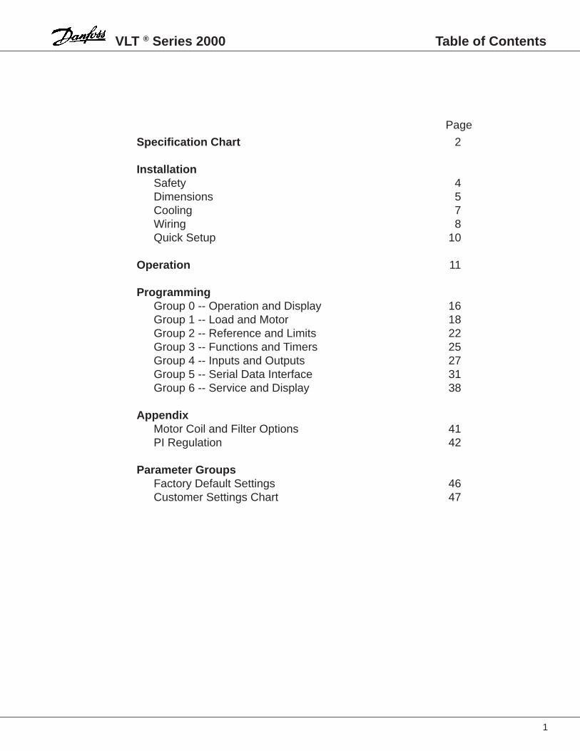
1 VLT ® Series 2000 Table of Contents Page Specification Chart 2 Installation Safety 4 Dimensions 5 Cooling 7 Wiring 8 Quick Setup 10 Operation 11 Programming Group 0 -- Operation and Display 16 Group 1 -- Load and Motor 18 Group 2 -- Reference and Limits 22 Group 3 -- Functions and Timers 25 Group 4 -- Inputs and Outputs 27 Group 5 -- Serial Data Interface 31 Group 6 -- Service and Display 38 Appendix Motor Coil and Filter Options 41 PI Regulation 42 Parameter Groups Factory Default Settings 46 Customer Settings Chart 47
-
Upload
duongxuyen -
Category
Documents
-
view
222 -
download
0
Transcript of VLT Series 2000 Table of Contents - besturingen.com · 1 VLT ® Series 2000 Table of Contents Page...
1
VLT ® Series 2000 Table of Contents
Page
Specification Chart 2
InstallationSafety 4Dimensions 5Cooling 7Wiring 8Quick Setup 10
Operation 11
ProgrammingGroup 0 -- Operation and Display 16Group 1 -- Load and Motor 18Group 2 -- Reference and Limits 22Group 3 -- Functions and Timers 25Group 4 -- Inputs and Outputs 27Group 5 -- Serial Data Interface 31Group 6 -- Service and Display 38
AppendixMotor Coil and Filter Options 41PI Regulation 42
Parameter GroupsFactory Default Settings 46Customer Settings Chart 47

VLT ® Series 2000
4
WARNING
The VLT® Series 2000 AdjustableFrequency Drive (AFD) containsdangerous voltages when connected toline voltage. Only a competent electricianshould carry out the electrical installation.
Improper installation of the motor or the AFD may causeequipment failure, serious injury or death. Follow thismanual and local and national safety codes.
The motor may start without warning during operationand programming of the parameters. Activate the STOPkey on the VLT keypad when changing data.
Danfoss CE marks our VLT® Adjustable FrequencyDrives (AFD) according to the Electro MagneticCompatibility (EMC) Directive 89/336/EEC and Low-Voltage Directive 73/23/EEC.
When the installation specification is followed andshielded motor cables are used per instruction manualsprovided with the drive, we guarantee the AFD complieswith the EMC Directive 89/336/EEC.
It is possible for the VLT to start upon application of ACpower. DO NOT attempt any maintenance on the VLT,motor or system machinery without verifying that the ACpower has been disconnected.
DO NOT touch any electrical parts after the AC line hasbeen disconnected for at least 14 minutes. This allowsfor capacitor discharge.
NOTE: The STOP key on the VLT keypad DOES NOTdisconnect the AC line.
It is the responsibility of the user or the person installingthe AFD to provide proper grounding and branch circuitprotection for incoming power and motor overloadprotection according to the National Electrical Code(NEC) and local codes.
Upon request we will issue a declaration of conformity tothe EMC and low-voltage directives. A manufacturer'sdeclaration for the Machinery Directive 89/392/EEC isalso available.
Caution:
Danfoss VLT ® and CE Marking
Installation; Safety

5
VLT ® Series 2000
VLT 2010-2030Single-phase, 220-240 VThree-phase, 208-240 V
VLT 2010-2030 with moduleSingle-phase, 220-240 VThree-phase, 208-240 V
NOTE:Minimum space above and below the unit is 4 inches.Minimum space to the sides of the unit is 0 inches.
NOTE:Minimum space above and below the unit is 4 inches.Minimum space to the sides of the unit is 0 inches.
Installation; Dimensions
7.1(180)
3.5(90)
4.3(110)
9.3(235)
10.2(260)
0.21(5.5)
0.17(4.5)
0.43(11)
0.29(7.5)
0.21(5.5)
7.1(180)
3.5(90)
4.3(110)
14.3(338)
14.3(363)
0.21(5.5)
0.17(4.5)
0.43(11)
0.29(7.5)
0.21(5.5)

VLT ® Series 2000
6
VLT 2020-2050Three-phase, 380-415/460 VVLT 2040-2050Three-phase, 208-240 V
VLT 2020-2050 with moduleThree-phase, 380-415/460 V
NOTE:Minimum space above and below the unit is 4 inches.Minimum space to the sides of the unit is 0 inches.
NOTE:Minimum space above and below the unit is 4 inches.Minimum space to the sides of the unit is 0 inches.
Installation; Dimensions
7.1(180)
3.5(90)
4.3(110)
13.2(335)
14.2(360)
0.21(5.5)
0.17(4.5)
0.43(11)
0.29(7.5)
0.21(5.5)
7.1(180)
3.5(90)
4.3(110)
17.2(437)
18.2(462)
0.21(5.5)
0.17(4.5)
0.43(11)
0.29(7.5)
0.21(5.5)

7
VLT ® Series 2000
Mechanical Installation
The VLT Series 2000 is cooled by natural or forced airconvection. Therefore air must be able to pass freelyunder and over the unit
The VLT adjustable frequency drive must be mounted ona flat vertical surface.
To enable the VLT to get rid of the cooling air, you mustallow free air space both above and below the adjustablefrequency drive.
The ambient temperature must not exceed 40°C so thatthe VLT can dispose of its power loss.
Side by Side Mounting
The VLT Series 2000 adjustable frequency drive can beinstalled side by side. There is no need for any space forcooling along the side of the enclosure.
Installation; Cooling
MinimumClearance4 Inches(100 mm)
MinimumClearance4 Inches(100 mm)
VLT
VLT®
®
Menu
Data
StopReset
Jog
Start
Fwd.Rev.
+
–
Variable Speed Drive
MOTOR BRLINE
Alarm On
VLT
VLT®
®
Menu
Data
StopReset
Jog
Start
Fwd.Rev.
+
–
Variable Speed Drive
MOTOR BRLINE
Alarm On
VLT
VLT®
®
Menu
Data
StopReset
Jog
Start
Fwd.Rev.
+
–
Variable Speed Drive
MOTOR BRLINE
Alarm On

VLT ® Series 2000
8
CAUTION:It is the responsibility of the user or the person installingthe drive to provide proper grounding and branch circuitprotection for incoming power and motor overload.National Electrical Codes (NEC) and local codes must beobserved.
PrefusesPrefuses must be installed in the AC line feeding theadjustable frequency drive.
WiringCables for the control signals and the brake cable mustbe shielded in order to comply with EMC specifications.The maximum cable length and the maximum cablecross section is listed in the Specification Chart.
The Electronic Thermal Relay (ETR) in UL listed VLT'sprovides class 20 motor overload protection inaccordance with NEC in single motor applications, whenparameter 315 is set to Trip [2] and parameter 107 is setto nominal motor (nameplate) current.
The correct sizes and ratings can be found in theSpecification Chart.
Any motor cable shielding is connected to the groundterminals in the adjustable frequency drive and the motor.If non-shielded cables are used, the control inputs canoccasionally be subject to signal disturbances. Normallysuch a disturbance will not affect the VLT.
Signal Wiring
Line and Motor Wiring
Installation; Wiring
VLT
VLT®
®
Menu
Data
StopReset
Jog
Start
Fwd.Rev.
+
–
Variable Speed Drive
MOTOR BRLINE
Alarm On
01 02 03
0UT
46
+24
V 1
2D
IN1
18
DIN
2 1
9 20D
IN3
27
DIN
4 2
910
V 5
0A
IN 5
3 55A
IN 6
0 61R
S 2
32 R
XD
71
RS
232
TX
D 7
2
L1 L2 L3 PE U V W 81 82
TmaxM

9
VLT ® Series 2000
Typical Wiring Example
Installation; Wiring
L1 L2 L3 PE U V W 81 82
TmaxM
01 02 03
0UT
46
+24
V 1
2D
IN1
18
DIN
2 1
9 20D
IN3
27
DIN
4 2
910
V 5
0A
IN 5
3 55A
IN 6
0 61R
S 2
32 R
XD
71
RS
232
TX
D 7
2
92 L
2
93 L
3
94 94 /
95
96 97 98 81 8291 L
1
1k
ST
AR
T/S
TO
P(p
ar. 4
02)
RE
VE
RS
ING
(par
. 403
)
JOG
GIN
G(p
ar. 4
05)
L1
L2
L3
L1 L2 L3 PE
N
L1
LINE
LINE MOTOR BRAKE
Three-phase connection
Single-phase connection

VLT ® Series 2000
10
Quick Setup
If you know how to operate the VLT Series and and arefamiliar with the menus and parameters, go directly to theHow to Program section of this manual.
How to Program
This setup is based on the assumption that you wantyour VLT to operate with the following:
1. External start/stop2. Potentiometer connected for external speed control3. Option to change rotation direction4. Option to select a fixed speed (Jog)
If you are not familiar with the VLT Series AdjustableFrequency Drive refer first the Operation section of thismanual.
NOTE: If you use a brake module, you must programparameter 300. If you want local operation via the displaykeys you must program parameters 003 and 004. Tostore the data press the "Menu" key.
If you have connected your VLT as shown in the TypicalWiring Example, you must program the parameters aslisted in the chart below.
Standard motor with constant torque load without a brake module on the adjustable frequenct drive
Step Parameter Designation Settings Display Indication
1 000 Language Choose English ENGLISH
2 103 Motor output Read motor plate
3 104 Motor voltage Read motor plate
4 105 Motor frequency Read motor plate
5 201 Minimum frequency Set wanted frequency
6 202 Maximum frequency Set wanted frequency
7 215 Ramp up 1 Set wanted ramping time
8 216 Ramp down 1 Set wanted ramping time
9 Start the This is done by supplying terminals 18 and 27 with 24 VDC fromadjustable frequency the adjustable frequency drive's terminal 12 or by using andrive external 24 VDC voltage.
If a brake module is mounted, program the following parameters
Step Parameter Designation Settings Display Indication
1 300 Brake function If a brake module is used, choose Applied APPLIED
2 Start the This is done by supplying terminals 18 and 27 with 24 VDC fromadjustable frequency the adjustable frequency drive's terminal 12 or by using andrive external 24 VDC voltage.
If you want local operation and start, program the following parameters
Step Parameter Designation Settings Display Indication
1 003 Operation site Choose Loc/ext stop LOC/EXT STOP
2 004 Local reference Record wanted output frequency by means of the "+" and "–" keys
Installation; Quick Setup

11
VLT ® Series 2000 Operation
All Danfoss VLT Series 2000 AC drives utilize the samecontrol card throughout the entire HP range. The VLT controlpanel consists of a keyboard and a display.
The keyboard is used for two purposes: local control andprogramming. The display communicates VLT, motor andapplication information to the operator.
Located on the control panel is a red and green status LED.When the green status LED is illuminated, there is AC powerapplied to the VLT. The red LED is used for alarm indications.In an ALARM MODE, the LED will flash.
The display is a three-line LCD display. Line A is used foroperating displays. It shows the value corresponding to thesetting in DISPLAY MODE. The set value remains in thedisplay line during programming of parameters. Line Bshows information about parameters and direction of motoroperation. Line C shows information about status and setupor data value.
VLT Control Panel
Menu
Data
Jog Fwd.Rev.
StopReset
Start
+
–
Alarm On
0000000000000060USE±000000000015
60 HzA
B
C
VLT ® Series 2000
12
Operation
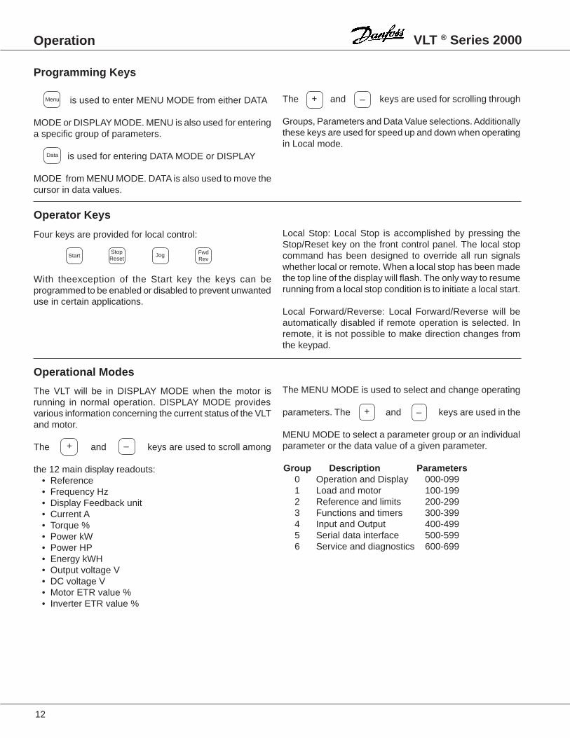
The and keys are used for scrolling through
Groups, Parameters and Data Value selections. Additionallythese keys are used for speed up and down when operatingin Local mode.
Local Stop: Local Stop is accomplished by pressing theStop/Reset key on the front control panel. The local stopcommand has been designed to override all run signalswhether local or remote. When a local stop has been madethe top line of the display will flash. The only way to resumerunning from a local stop condition is to initiate a local start.
Local Forward/Reverse: Local Forward/Reverse will beautomatically disabled if remote operation is selected. Inremote, it is not possible to make direction changes fromthe keypad.
The MENU MODE is used to select and change operating
parameters. The and keys are used in the
MENU MODE to select a parameter group or an individualparameter or the data value of a given parameter.
Group Description Parameters0 Operation and Display 000-0991 Load and motor 100-1992 Reference and limits 200-2993 Functions and timers 300-3994 Input and Output 400-4995 Serial data interface 500-5996 Service and diagnostics 600-699
is used to enter MENU MODE from either DATA
MODE or DISPLAY MODE. MENU is also used for enteringa specific group of parameters.
is used for entering DATA MODE or DISPLAY
MODE from MENU MODE. DATA is also used to move thecursor in data values.
Four keys are provided for local control:
With theexception of the Start key the keys can beprogrammed to be enabled or disabled to prevent unwanteduse in certain applications.
The VLT will be in DISPLAY MODE when the motor isrunning in normal operation. DISPLAY MODE providesvarious information concerning the current status of the VLTand motor.
The and keys are used to scroll among
the 12 main display readouts:• Reference• Frequency Hz• Display Feedback unit• Current A• Torque %• Power kW• Power HP• Energy kWH• Output voltage V• DC voltage V• Motor ETR value %• Inverter ETR value %
Programming Keys
Data
Operator Keys
FwdRev
Menu –+
StartStop
ResetJog
Operational Modes
+ –
–+

13
VLT ® Series 2000 Operation
The parameter number consists of three digits as shown.
The left digit indicates the Group, and the two digits at theright specify the parameter number in the specific Group.
To travel through the available Groups, use the key
followed by the or keys.
or . All the other data value words that can
be chosen will be shown one at a time by using the
or key.
Due to space considerations, several words have beenabbreviated on the display.
When leaving the DATA MODE, the word shown in thedisplay will be stored.
Please Note: In order to change the data value of some
parameters, it is necessary to press .
It is possible to return to DATA MODE and program theparameter that was blocked by the time-out with a single
stroke on .
Note: The 20 second time-out does not occur in parameter004, Local Reference.
After the first power up, the drive is in DISPLAY MODE. Toprogram the VLT's various Groups, use the MENU key toenter the MENU GROUP MODE.
Parameters in each group can be entered in the selected
group by also using the key followed by or
key.
The Data Value can be a continuous (numerical) value offigures within a specified range (i.e., volts, Hz, etc.), or itcan be a discrete value represented by the text.
The new data value will be stored in the software whenleaving the DATA MODE.
Please Note: It is necessary to press to stop the
motor before changing the data value of some parameters.
If the data value of the chosen parameter is a discrete value,a text will appear in the display. The text shown representsthe chosen parameter. In order to change it, press
If the VLT is left in DATA MODE, a 20 second time-out willprevent unwanted change of data.
The software leaves DATA MODE after 20 seconds if nooperation is recorded.
Parameter Numbering
Moving through the Program
Changing a Parameter number in a Group
Changing a Numerical Data Value
Time-out
–+
Menu
+ –
Menu
StopReset
+ –
–
+
StopReset
Data

VLT ® Series 2000
14
Operation
TRIP000000000000MOTOR TRIP000000
ALARM Reset mode —
Cause of alarm —
FREQUENCY RUN OK LOCAL. 1
15.0 HzShows value and unit —
Defines the display —Status, and source of control —
— Parameter name— setup number
0 . .OPERATION AND0DISPLAY 0000
0.0 Hz — Parameter group— Name
0000LANGUAGE0000ENGLISH000000001
0.0 HzFlashing parameter numbe —
0 = Cursor flashes —Selected data value —
LANGUAGE0ENGLISHENGLISH000000001
0.0 Hz
Parameter number flashes — 0.. = Cursor flashes
Display Mode
Menu Mode
Parameter Mode
Data Mode
Alarm Mode
E = Cursor flashes —Selected data value
— Direction of rotation— Setup number
— Parameter name— Setup number
NOTE: To store the newly selected data value, you must quit Data group, by pressing "Menu".
NOTE: If TRIP is displayed the operation has stopped and you must press the "Reset" key to reset the VLT.
NOTE: If TRIP LOCKED is dispalyed you must switch off the VLT and switch it on again. Press the "Reset" key to reset the VLT.
Operational Modes

15
VLT ® Series 2000 Operation
Menu
Data
Jog Fwd.Rev.
StopReset
Start
+
–
Alarm On
0000000000000060USE±000000000015
60 Hz
From any state
Alarm Mode
Group GroupMenu
Data
+
–
0 1
+
–
+
–
6 0
Menu Mode
StopReset
Display Mode
From any state
Menu Data+The figure below shows how to switch between the different groups.
000
001
00X
000
+
+
+
+
–
–
–
–
Menu Menu
Data Menu
English Deutsch
Data Mode
+ +
––
20 Sec.No ActionTime Out
Parameter Mode

16
★ = ROM default setting. Text in ( ) = display text. Figures in [ ] are used when communicating with the bus.
Programming VLT® Series 2000
Group 0 -- Operation and Display
000 Language (LANGUAGE)Value:
★ English (ENGLISH) [0]German (DEUTSCH) [1]French (FRANCAIS) [2]Danish (DANSK) [3]
Function and Description:
Determines the language of the display.You can choose between English, German, French andDanish.
001 Menu Setup Select (MENU SETUP)Value:
★ Setup 1 (SETUP 1) [1]Setup 2 (SETUP 2) [2]Multi-setup (MULTI SETUP) [5]
Setup Terminal 291 02 1
Function:
You can select a menu setup which is different from thefactory setting and store it in Setup 1 or Setup 2.
Description:
You start by selecting the setup you want to make or alter.You can choose between Setup 1 or setup 2. Then you canalter any data value you like. Your alterations make a setupdifferent from the factory setting. If you choose Multi-setupyou can switch between the two setups via terminal 29. Theparameters which can be chosen for the two setups havebeen specially selected. Refer to the Parameter/DefaultSettings chart in the back of this manual.
002 Setup Copy ((MENU SET COPY)Value
★ No copying (DO NOT COPY) [0]Copy setup 1 to 2 (COPY 1 TO 2) [6]Copy to 2 to 1 (COPY 2 TO 1) [7]Copy from fact. setting to 1 (Fact. setting ➔1) [8]Copy from fact. setting to 2 (Fact. setting ➔2) [9]
Function:
You can copy Setup 1 to Setup 2 and vice versa. You canalways copy the factory setting back to Setup 1 or Setup 2.
Description:
The copying starts when you have entered the desiredcopying function and Data mode is left by pressing the“Menu” key, or after 20 seconds of no activity. Line 3 in thedisplay flashes while copying is in progress. Time out doesnot activate the copying function.
003 Operation Site (LOCAL /REMOTE)Value:
★ Remote (REMOTE) [0]Local with external stop (LOC/EXT./STOP) [1]Local (LOCAL) [2]Local and remote (LOCAL - REMOTE) [3]
Function:
You can choose four different operation sites: Remote,Local with external stop, Local and Local and remote.
Description:
If you choose Remote, you can control the adjustablefrequency drive via the control terminals. However, you canstill use the stop key of the control panel (provided youhave not chosen to disable this function in parameter (007).If you choose Local with external stop you must disconnectthe connection between terminals 12 and 27 to activatestop. Local with external stop can only be chosen if Motorcoasting, Quick stop, Reset and motor coasting or Stophave been chosen in parameter 404 (terminal 27).Choose Local if you want to operate the unit via thekeyboard (must be activated in parameter 007). Local andremote adds local and external reference. This function isselected for access to local reference even when the unit isoperated remotely.

17
★ = ROM default setting. Text in ( ) = display text. Figures in [ ] are used when communicating with the bus.
VLT® Series 2000 Programming
004 Local Reference (LOCAL SPEE)Value:
0 to fMAX
Function:
You choose Local reference if you want to set the speed(frequency) via the control panel.
Description of choice:
To use this parameter you must choose Local with externalstop or Local and remote in parameter 003. the outputfrequency of the adjustable frequency drive can bechanged by means of the "+" and "–" keys. If the AC line isdisconnected the value changes to 0.00. Parameter 004cannot be controlled via the serial bus, RS 232.There is no automatic switch back to Parameter Group fromthis parameter. In parameter 010 you can lock datachanges in parameter 004.
005 Display Value (VALUE AT M)Value:
1 to 9999 ★ 1000Function:
Yoy can choose to have the speed/frequency displayedwithout the unit Hz behind the value.
Description of choice:
The value will only be read out if Display is selected inDisplay Group.It is not possible to change Hz to another unit.
006 Local Reset (LOCAL RESE)Value:
Disable (DISABLE) [0]★ Enable (ENABLE) [1]
007 Local Start/Stop (LOCAL START/STOP)Value:
Disable (DISABLE) [0]★ Enable (ENABLE) [1]
008 Local Reversing (LOCAL/FWD/REV)Value:
★ Not possible (DISABLE) [0]Possible (ENABLE) [1]
009 Local Jog (LOCAL JOG)Value:
Disable (DISABLE) [0]★ Enable (ENABLE) [1]
010 Local Reference (LOC REFERE)Value:
Disable (DISABLE) [0]★ Enable (ENABLE) [1]
Enable and save (ENABLE AND SAVE) [2]Function:
You can enable/disable the function via the control panel.You also can choose whether it must be possible to changethe output frequency via parameter 004.
Description:
If you choose Disable in parameter 006, 007, 008 or 009you cannot activate the function via the control panel.If you choose Disable in parameter 010 the outputfrequency cannot be changed via parameter 004.You can prevent data change by setting parameter 013 toLocked.If you choose Enable and savs a change of local speedreference will be saved automattically after 15 sec.
013 Data Change Lock (DATA CHC. LOCK)Value:
★ Not locked (NOT LOCKED) [0]Locked (LOCKED) [1]
Function:
There is a way to avoid unintended programming.Description:
If you choose Locked you cannot make any data change inany parameter. However, it is still possible to change thelocal reference.If data change is attempted with data change lock, thedisplay shows: DATA LOCKED.

18
★ = ROM default setting. Text in ( ) = display text. Figures in [ ] are used when communicating with the bus.
Programming VLT® Series 2000
Group 1 -- Load and Motors
101 Speed Control (SPEED CONT)Value:
Open loop (OPEN LOOP) [0]★ Slip comp. (SLIP COMP) [1]
Closed loop (CLOSED LOOP) [2]Function:
You can choose among three different kinds of speedcontrol: Open loop, Slip compensated and Closed loop.
Description:
Choose Slip compensation for normal operation , where thespeed must be constant no matter what the load is. ChooseOpen loop when the motors used are parrellel connected orwhen synchronous motors are used.Choose Closed loop when you want operation with processfeedback. For closed loop opereation you must choose thefeedback type in parameter 114 (current, voltage or pulses).
102 Setting of Current Limit (SET CUR.LI)Value:
★ Pre-programmed value (VALUE SET) [0]Voltage signal (10VDC SIGNAL) [1]Current signal (20 mA SIGNAL) [2]
Function:
You can choose to control the speed by means of thecurrent limit. This makes indirect torque control possible.The current limit is set in parameter 209, or by means of acurrent or voltage signal in parameter 412 or parameter413.
Description:
Choose between controlling the current limit via parameter209 or one of the analog inputs, terminal 53 0r 60. 10V/20mA corresponds to 160% current (2030: 140%).Do not select the same signal for PI control.
103 Motor Power (MOTOR POWE)Value:
Under size [0]★ Nom. size [1]
Over size [2]Function:
This parameter allows a choice of the kW value that bestmatches the rated motor power.The factory setting will be for the nominal kW equivalent ofthe horsepower size on the drive nameplate.
103 (continued)Description:
Check the rated motor power on the motor nameplate. If itis not equal to the nominal horsepower rating on the drivenameplate, select the most appropriate size (1 HP = 0.746kW). Parameters 107, 108, 109, 110, 111 and 112 changeautomatically when the value in parameter 103 is changed.
104 Motor Voltage (U M,N)(MOTOR VOLT)Value:
Only 200-230 V units200 V [0]208 V [1]
★ 220 V [2]230 V [3]240 V [4]
Only 380-460 V units380 V [0]
★ 400 V [1]415 V [2]440 V [3]460 V [4]
Function:
The rated voltage that most closely matches the motornameplate voltage can be selected.
Description:
You can choose among different voltage values. The valueis selected on the basis of the data on the motor plate.Parameters 107, 108, 109, 110, 111 and 112 changeautomatically when the value in parameter 104 is changed.
105 Motor Frequency (f N)(MOTOR FREQ)Value:
★ 50 Hz (50 Hz) [0]60 Hz (60 Hz) [1]87 Hz (87 Hz) [2]100 Hz (100 Hz) [3]
Function:
Choose the frequency that corresponds to the rated motorfrequency.
Description:
You can choose among 4 different frequency values. Thevalue is selected on the basis of the data on the type plateof the motor.The U/f ratio in parameter 111 is changed automatically.
19
★ = ROM default setting. Text in ( ) = display text. Figures in [ ] are used when communicating with the bus.
VLT® Series 2000 Programming
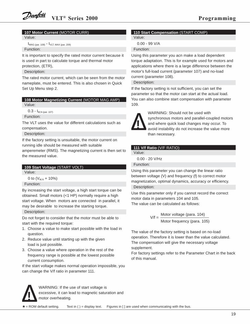
110 Start Compensation (START COMP)Value:
0.00 - 99 V/AFunction:
Using this parameter you acn make a load dependenttorque adaptation. This is for example used for motors andapplications where there is a large difference between themotor's full-load current (parameter 107) and no-loadcurrent (parameter 108).
Description:
If the factory setting is not sufficient, you can set theparameter so that the motor can start at the actual load.You can also combine start compensation with parameter109.
111 V/f Ratio (V/F RATIO)Value:
0.00 - 20 V/HzFunction:
Using this parameter you can change the linear ratiobetween voltage (V) and frequency (f) to correct motormagnetization, optimal dynamics, accuracy or efficiency.
Description:
Use this parameter only if you cannot record the correctmotor data in parameters 104 and 105.The value can be calculated as follows:
Motor voltage (para. 104)
Motor frequency (para. 105)
The value of the factory setting is based on no-loadoperation. Therefore it is lower than the value calculated.The compensation will give the necessary voltagesupplement.For factory settings refer to the Parameter Chart in the backof this manual.
107 Motor Current (MOTOR CURR)Value:
IMAG (par. 108) - IVLT, MAX (par. 209)
Function:
It is important to specify the rated motor current because itis used in part to calculate torque and thermal motorprotection, (ETR),
Description:
The rated motor current, which can be seen from the motornameplate, must be entered. This is also chosen in QuickSet Up Menu step 2.
108 Motor Magnetizing Current (MOTOR MAG AMP)Value:
0.3 - IM,N (par. 107)
Function:
The VLT uses the value for different calculations such ascompensation.
Description:
If the factory setting is unsuitable, the motor current onrunning idle should be measured with suitableamperemeter (RMS). The magnetizing current is then set tothe measured value.
109 Start Voltage (START VOLT)Value:
0 to (VM,N + 10%)Function:
By increasing the start voltage, a high start torque can beobtained. Small motors (<1 HP) normally require a highstart voltage. When motors are connected in parallel, itmay be desirable to increase the starting torque.
Description:
Do not forget to consider that the motor must be able tostart with the required torque:1. Choose a value to make start possible with the load in
question.2. Reduce value until starting up with the given
load is just possible.3. Choose a value where operation in the rest of the
frequency range is possible at the lowest possiblecurrent consumption.
If the start voltage makes normal operation impossible, youcan change the V/f ratio in parameter 111.
V/f =
∆! WARNING: Should not be used withsynchronous motors and parallel-coupled motorsand where quick load changes may occur. Toavoid instability do not increase the value morethan necessary.
∆! WARNING: If the use of start voltage isexcessive, it can lead to magnetic saturation andmotor overheating.

20
★ = ROM default setting. Text in ( ) = display text. Figures in [ ] are used when communicating with the bus.
Programming VLT® Series 2000
112 Slip Compensation (SLIP COMP.)Value:
0.0 - 20 HzFunction:
Slip Compensation increases the output frequency andvoltage of the VLT adjustable frequency drive with anincreasing load to compensate for the motor's increasingslip (loss). This achieves a load-independent speed.
Description:
Choose a value so that the speed remains constant whenthe load increases. If the value is too high the speedincreases with the load. This may lead to unstable motoroperation.When you use synchronous motors and motors connectedin parallel, set slip compensation to 0 Hz. Slipcompensation should be avoided in case of high dynamics.
114 Feedback Signal (FEEDBACK T)Value:
Voltage (VOLTAGE) [0]★ Current (CURRENT) [1]
Pulses (PULSES) [2]Function:
This parameter allows a choice of process feedback signalin a closed loop system, as chosen in parameter 101. It hasno effect if parameter 101 is set to OPEN LOOP.For further information, see the section on the PIDcontroller.
Description of choice:
If a PID controller is used, one of the inputs on terminal 29(parameter 405), terminal 53 (parameter 412) or terminal60 (parameter 413) must be used for the feedback signal.The same type of signal cannot be the reference signal.
119 FF Factor (FEED FWD F)Value:
0 to 500% ★ 100%Function:
This parameter is used in connection with a PI controller.The FF factor makes a large or small part of the referencesignal around the PID controller so that the PI controlleronly affects part of the control signal. Any change of thesetpoint will affect the motor rpm directly. The FF factorgives high dynamics at changes of the setpoint and lessoverswing.
Description of choice:
You can choose the required % value in the interval fMIN-fMAX
Choose a value above 100% if the setpoint variations areonly minor.
120 Control Range (CONTRL RAN)Value:
0 to 100% ★ 100%Function:
The regulator range (bandwidth) limits the output from thePID controller as a % of fMAX.
Description of choice:
A desired % value of fMAX can be selected. If the regulatorrange is reduced, speed variations will become smallerduring initial adjustment.
121 Proportional Gain (PROPRT/L G) Value:
0.01 to 10.00 ★ 0.01Function:
The proportional gain sets the amplification factor of theerror (the difference between the feedback signal and thesetpoint).
Description of choice:
Quick regulation is obtained at a high amplification, but ifthe amplification is too high, the process may becomeunstable due to overshoot.
122 Integral Time (INTEGRAL T)Value:
0.01 to 7200 sec. ★ OFFFunction:
The integral time determines how long the PI controllertakes to correct the fault. The integral time results in a delayof the signal, and therefore has a dampening effect that willimprove stability.
Description of choice:
Quick regulation is obtained through a short integral time.However, if this time is set too short, the process willbecome unstable. If the integral time is set long, regulationbecomes unnecessarily slow. Off means that the function isinactive.
∆! WARNING: The output frequency is limited by0.9 x fMIN and 1.1 x fMAX no matter what the bandwidth setting is. The controller can therefore beactive without affect the output frequency canexceed fMAX by 10%.

21
★ = ROM default setting. Text in ( ) = display text. Figures in [ ] are used when communicating with the bus.
VLT® Series 2000 Programming
125 Feedback Factor (FEEDBACK F)Value:
0 to 500% ★ 100%Function:
The feedback factor is used if the transmitter cannot beselected optimally for the scale range of the setpoint.
Description of choice:
This parameter is only used if the feedback signal inparameter 114 is not of a suitable level. If you choose 100%the feedback signal is not changed.

22
★ = ROM default setting. Text in ( ) = display text. Figures in [ ] are used when communicating with the bus.
Programming VLT® Series 2000
Group 2 -- References and Limits
200 Frequency Range (FREQUE RANGE)Value:
★ 0 to 120 Hz [0]0 to 500 Hz [1]
Function:
Using this parameter you can set and thus limit the outputfrequency range of the VLT adjustable frequency drive.
Description:
In most cases you can use 0-120 Hz.
WARNING: Only choose 0-500 Hz if you usespecial motors designed for high speeds.
201 Minimum Frequency (MIN FREQUE)Value:
0.0 to fMAX ★ 0Function:
Choose the minimum frequency that corresponds to theminimum speed at which the motor is to run. The minimumfrequency can never be higher than the maximumfrequency, fMAX.
Description:
A value from 0.0 Hz to the max. frequency (fMAX) selected inparameter 202 can be chosen. This is also chosen in QuickSet Up Menu step 5.
202 Maximum Frequency (MAX FREQUE)Value:
0.0 - value in para. 200 ★ 60 HzFunction:
Choose a maximum frequency that corresponds to themaximum speed at which the motor is to run. The maximumfrequency can never be lower than the minimum frequency,fMIN.
Description:
A value from fMIN to the value selected in parameter 200 forfMAX (120 Hz or 500 Hz) This is also chosen in Quick SetUp Menu step 6.
When the PI controller is active the maximumfrequency can be exceeded by 10%. The sameapplies when slip compensation is active.
∆!
203 Jog Frequency (JOG FREQUE)Value:
0.0 to fMAX ★10 HzFunction:
The jog frequency is the fixed output frequency at which thedrive runs when the jog function is activated.
Description:
The jog frequency can be selected to be lower than fMIN
(parameter 201) but the highest output frequency is limitedby fMAX (parameter 202).
204 Digital Reference Type (DIG. REF.)Value:
★ Sum (SUM) [0]Relative (RELATIVE) [1]
Function:
The digital references are generated internally in the unitand presented as a percentage of the difference betweenthe fMAX and fMIN selected in parameters 201 and 202, addedto fMIN.
Description:
If Sum is selected, one of the digital references (parameters205-208) is added as a percentage of the differencebetween fMAX and fMIN with the other references. If Relativeis selected, one of the digital references )parameters 205-208) is added as a percentage of the sum of the otherreferences.
205 Digital Reference 1 (REF. 1 DIG)Value:
-100.00% to +100.00% ★ 0 % of fMAX .- fMIN
206 Digital Reference 2 (REF. 2 DIGI)Value:
-100.00% - +100.00% ★ 0 % of fMAX .- fMIN
207 Digital Reference 3 (REF. 3 DIG)Value:
-100.00% - +100.00% ★ 0 % of fMAX. - fMIN

23
★ = ROM default setting. Text in ( ) = display text. Figures in [ ] are used when communicating with the bus.
VLT® Series 2000 Programming
208 Digital Reference 4 (REF. 4 DIG)Value:
-100.00% - +100.00% ★ 0 % of fMAX - fMIN
Function:
The digital speed references are generated internally in theunit and presented as a percentage of the differencebetween the fMAX and fMIN selected in parameters 201 and202, added to fMIN.
Description:
By means of terminal 29 you can switch between the otherreferences (terminal 29 = 0 V) and the sum of the other/digital references (terminal 29 = 24 V).You must select Digital reference in parameter 402 and 403to file one of the digital references:
Terminal 18/27 Terminal 190 0 Digital reference 11 0 Digital reference 20 1 Digital reference 31 1 Digital reference 4
209 Current Limit (CURRENT LI)Value:
0.3 to IVLT,MAX
Function:
Use this parameter to set the maximum intermittent outputcurrent. If the current limit is exceeded, the outputfrequency is reduced until the current falls to below thecurrent limit. The output frequency will not increase to thereference level until the current has fallen below the currentlimit.
Description of choice:
The value set at the factory corresponds to a load which is160% (VLT 2030, 3Ø 208-240 V: 140%) of the rated outputcurrent. If the current limit is to be used as motor protection,the rated motor current must be programmed. Parameter310 determines the length of time that the drive will run incurrent limit before an overcurrent fault. The load rangebetween 100 and 160% can be programmed, but it is onlyintended for intermittent operation therefore the unit canonly give an output of 160% (VLT 2030, 3Ø 208-240 V:140%) for 60 seconds. The intermittent operating time willbe extended as the load drops below 110%, and becomesunlimited at 100%.
If the switching frequency is higher than 4.5 kHzthis period will be shorter.
210 Warning: Low Frequency (LO FREQ. W)Value:
0 to 500 Hz ★ 120 HzFunction:
Set the low frequency (fLOW) at which the warning is tooccur.
Description:
If the output frequency falls below the frequency set (fLOW),the display shows LO FREQ. WARN. You can also choose to program the signal outputs inparameters 408 and 409 to give a signal.
211 Warning: High Frequency (HI FREQ. W)Value:
0 to 500 Hz ★ 120 HzFunction:
Set the high frequency (fHIGH) at which the warning is tooccur.
Description:
If the output frequency increases above the frequency set(fHIGH), the display will read HI FREQ. WARN. You can also choose to program the signal outputs inparameters 408 and 409) to give a signal.
213 Warning: High Current (HI CURR. W)Value:
0.0 to IVLT,MAX ★ IVLT,MAX
Function:
Set the current (IHIGH) at which the warning is to occur.Description of choice:
If the motor current rises above the IHIGH programmed, thedisplay will read HI CURR. WARN.You can also choose to program the signal outputs inparameters 408 and 409 to give a signal.
215 Accel (ramp-up) Time (RAMP UP TI)Value:
0.1 to 800 sec. ★ 5 sFunction:
Using this parameter you can record the requiredacceleration time from 0.1 Hz to the rated output frequency(parameter 105).
Description:
To ensure the fastest possible start, choose a value for theramp-up time so that the current limit is not activated. Theramp-up time is always defined as the acceleration timefrom 0 Hz to the rated motor frequency.

24
★ = ROM default setting. Text in ( ) = display text. Figures in [ ] are used when communicating with the bus.
Programming VLT® Series 2000
216 Decel (ramp-down) Time (RAMP DOWN)Value:
0.1 to 800 sec. ★ 5 sFunction:
Using this parameter you can record the requireddeceleration time from rated output frequency to 0 Hz.
Description:
The ramp-down time can be selected in the range 0.1-800seconds. If the ramp-down time is too short the VLT'svoltage limit becomes active, which will extend the ramp-down time. Short ramp-down times will require a VLT unitwith a brake function and installation of a brake resistor.The ramp-down time is always defined as the decelerationtime from the rated motor frequency to 0 Hz.
218 Quick Stop Ramp (QUICK STOP RAMP)Value:
0.1 - 800 sec. ★ 1 sFunction:
Using this parameter you can choose an alternativedeleceration ramp - a programmable quick stop ramp.
Description of choice:
The ramp-down time can be selected in the range 0.1 - 800seconds, calculated from the rated frequency to 0 Hz. If theramp-down time is too short the VLT's voltage limitbecomes active, which will extend the ramp-down time.Short ramp-down times will require a VLT unit with a brakefunction and installation of a brake resistor.
224 Carrier Frequency (CARRIER FR)Value:
2.0 to 14.0 kHz ★ 4.5 kHzFunction:
The set value determines the carrier frequency of theinverter. Changing the carrier frequency may minimizeacoustic noise from the motor.
Description:
It is possible to change the carrier frequency between 2and 14 kHz. The disadvantages of operating at a highcarrier frequency are:- reduced continuous output current- reduced efficiency- higher capacitive leakage current- increased RFI radiation from the VLT
230 Digital Speed Up/Down (DIG. SPEED UP/DOWN)Value:
★ Disable (DISABLE) [0]Enable (ENABLE) [1]Enable and Save (ENABLE and SAVE) [2]
Function:
Using this parameter you can make the VLT adjustablefrequency drive lock the output frequency to the latestindicated speed reference.
Description:
You can choose to have either digital speed up/down(terminal 18/27 and 19) or other speed references. Whenyou have chosen Enable you must choose Speed Up(terminal 18) and Speed Down (terminal 19) in parameters402/404 and 403.When Enable and Save is selected a speed will be savedautomatically after new start-up.The other references will not be active so that the digitalreferences cannot be combined with other references.

25
★ = ROM default setting. Text in ( ) = display text. Figures in [ ] are used when communicating with the bus.
VLT® Series 2000 Programming
Group 3 -- Functions and Timers
300 Brake Function (START FREQ)Value:
★ Not Applied (NOT APPLIED) [0]Applied (APPLIED) [1]
Function:
Using this parameter you can inform the VLT adjustablefrequency drive that a brake function and a brake resistorhave been connected.
Description:
Choose Applied if you use a brake function and a brakeresistor.
306 DC Braking Time (DC-BRAKE T)Value:
0 to 60 sec. ★ 0 sec.Function:
Using this parameter you can record how long the DCbraking must be active
Description:
When you choose the braking time you must consider if youwant to maintain the braking torque or if you want to use astop function.The DC braking time must be ≠ 0 to activate DC braking.
307 DC Brake Cut-in Frequency (DC-BRK ON)Value:
0 to 500 Hz ★ 1 Hz.Function:
Using this parameter you can record the output frequencyat which DC braking must start when ramping down tostandstill.
Description:
The cut-in frequency depends on the application. The cut-infrequency must be ≠ 0 to activate DC braking. Instaed ofusing this parameter you can activate DC braking viaterminal 27 if a DC braking time and a DC brake voltagehave been recorded.
308 DC Brake Voltage (DC-BRK VOL)Value:
0 to 50 V ★ 10 VFunction:
Using this parameter you can record the DC brake voltagefor the motor.
Description:
The size of the voltage depends on the motor size. Thebigger the motor the lower the DC brake voltage.
WARNING: At frequent DC-braking the DC brakevoltage should not be too high. This is to avoidmotor overload. The DC brake voltage must be ≠0 to activate DC braking.
309 Reset Function (RESET MODE)Value:
★ Manual reset (MANUAL) [0]Automatic reset 1 (AUTO 1) [1]Automatic reset 5 (AUTO 5) [5]
Function:
Using this parameter you can choose how you want toreset an alarm
Description:
If you choose Manual Reset you must reset the VLTadjustable frequency drive via the keyboard or via terminals19, 27, or 29. The display shows TRIP.If you choose Auto Reset 1 the VLT will automatically try toreset once after alarm. The display shows AUTO START.As long as the display shows AUTOSTART the unit will tryto reset every 20 minutes.If you choose Auto Reset 5 thr VLT will automatically try toreset 5 times after alarm. The display shows AUTO START.
WARNING: The motor may start without warning.
∆!
∆!

26
★ = ROM default setting. Text in ( ) = display text. Figures in [ ] are used when communicating with the bus.
Programming VLT® Series 2000
310 Trip Delay at Current Limit (TRIP DLY@C)Value:
0 to 60 secs.★ Infinite at 61
Function:
Using this parameter you can record how long the currentlimit may be active before trip.
Description:
Record the delay time.
WARNING: If you choose Infinite, and your loadis between 105% and 160%, trip may occur aftera given interval.
315 Motor Thermal Protection (MOTOR THER)Value:
★ Off (PROTECT-OFF) [0]Only Warning (ONLY WARNING) [1]Trip (TRIP) [2]
Function:
The VLT adjustable frequency drive calculates whether themotor temperature exceeds the permissible limits. Thecalculation is based on 1.16 x rated motor current, as set inparameter 107.
Description:
Select Off (OFF) if no warning or tripping is required.Select Warning if only a warning is to be displayed whenthe motor is overloaded. The drive can be programmed togive an external warning through the signal outputs set byparameters 408 through 409.Select Trip if you want warning and trip to be displayed.
∆!
2000
1000
65432
100
6050403020
101.0 1.2 1.4 1.6 1.8 2.0
IM
IM NOM
MENU 107
t [s]
PAR 105
2xPAR 1050.2xPAR 105

27
★ = ROM default setting. Text in ( ) = display text. Figures in [ ] are used when communicating with the bus.
VLT® Series 2000 Programming
Group 4 -- Inputs and Outputs
402 Terminal 18 (TERMINAL 18 START)Value:
★ Start (START) [0]Pulse Start (PRESS CONT.) [1]No Function (NO FUNCTION) [2]Speed Up (SPEED UP) [3]Digital Reference Select (SPEED SELECT) [4]Reversing (REVERSING) [5]Reset and Start (RESET&START) [6]Motor Coasting & Start (COASTING/START) [7]
Function:
This parameter gives the motor various start signals.Description:
[0] Start :24 V on terminal 18 will make the motor ramp up to the setreference. 0 V will make the motor ramp down to stop.[1] Pulse Start:On selection of Press Cont. in parameter 402 andapplication of a pulse (24 V) to terminal 18, the motor willramp up to the set reference. Futher pulses do not haveany effect. (Therefore the motor must be stopped viaterminal 27 (parameter 404).[2] No Function:Locks the input.[3] Speed Up :This is used together with parameter 230. It is possible tomake the output frequency increase towards fMAX as longas 24 V is applied to terminal 18.At 0 V on terminal 18 the output frequency is maintained.Also refer to parameter 403).[4] Digital Reference Select:Together with parameter 403 you can choose between fourdifferent digital references:Terminal 18/27 Terminal 19
0 0 Digital reference 11 0 Digital reference 20 1 Digital reference 31 1 Digital reference 4
[5] Reversing:If the motor reverses when 24 V is applied to terminal 18, itwill change direction again when 0 V is applied.[6] Reset and Start:The function can be used as start when terminals 27 and19 are used to select between the digital references andterminal 29 to change setup (8 digital speeds). 24 V appliedto terminal 18 resets the VLT adjustable frequency driveand the motor ramps up to the set reference according tothe ramp-up time set in parameter 215.
[7] Motor Coasting and Start :24 V applied to terminal 18 makes the motor ramp up to theset reference..0 V applied to terminal 18 sets the motor coasting, runningfreely until it stops. This can be used in connection with amechanical brake.
403 Terminal 19 Reversing (TERM 19 REVERSING)Value:
★ Reversing (REVERSING) [0]Start Reversing (START REV) [1]No Function (NO FUNCTION) [2]Speed Down (SPEED DOWN) [3]Digital Reference Select (SPEED SELECT) [4]Reset (RESET) [5]
Function:
Using this parameter (terminal 19) you can e.g. change themotor's direction.
Description:
[0] Reversing:Reverses the motor, when 24 V is applied to terminal 19and changes the rotation direction again when 0 V isapplied to the terminal.[1] Start Reversing:Reverses the motor, when 24 V is applied to terminal 19.The motor stops when 0 V is applied to the terminal.[2] No Function:Locks the input.[3] Speed Down:This is used together with parameter 230. It is possible tomake the output frequency drop towards fMIN, as long as 24V is applied to terminal 19.At 0 V applied to terminal 19, the output frequency inquestion is maintained. Also refer to parameter 402.[4] Digital Reference Select:Together with parameter 402 you can choose between fourdifferent digital references:Terminal 18/27 Terminal 19
0 0 Digital reference 11 0 Digital reference 20 1 Digital reference 31 1 Digital reference 4
[5] Reset:Incase of alarm the VLT can be reset by applying 24 V toterminal 19.

28
★ = ROM default setting. Text in ( ) = display text. Figures in [ ] are used when communicating with the bus.
Programming VLT® Series 2000
404 Terminal 27 Stop (INPUT 27)Value:
Motor Coasting Stop (MTR. COAST) [0]Quick-Stop (Q-STOP) [1]DC Braking (DC-BRAKE) [2]
★ Reset and Motor Coasting (RST & COAST) [3]Stop (STOP=PRESS) [4]Reset and Start (RST & START) [5]Speed Down (SPEED DOWN) [6]Digital Reference Select (SPEED SELECT) [7]
Function:
Using this parameter (terminal 27) you can give the motorvarious stop signals.
Description:
[0] Motor coasting stop:If 0 V is applied to terminal 27 the motor will coast to a stop.[1] Quick Stop:If 0 V is applied to terminal 27 the motor will brake to a stopaccording to the ramp-down time set in parameter 218.A DC current brakes the motor after ramping down to 0,according to the setting of parameters 306-308.[2] DC Brake:If 0 V is applied to terminal 27 the motor will brake to a stopaccording to the settings of parameters 306 and 308.[3] Reset and Motor Coasting:If 0 V is applied to terminal 27 the motor will start coastingand the VLT adjustable frequency drive is reset.[4] Stop = Press:A circuit breaker between terminals 12 and 27, whenopened briefly causes ramp-down to stop.[5] Reset and Start:This can be used as a start function when you useterminals 18 and 19 to select a digital reference. 24 Vapplied to terminal 27 will make the adjustable frequencydrive reset and the motor ramp up to the set referenceaccording to the ramp-up time set in parameter 215.[6] Speed Down:This is used together with parameter 230. It is possible tomake the output frequency drop towards fMIN, as long as 24V is applied to terminal 27.At 0 V applied to terminal 27, the output frequency inquestion is maintained. Also refer to parameter 402.[7] Digital Reference Select:Together with parameter 402 you can choose between fourdifferent digital references:Terminal 18/27 Terminal 19
0 0 Digital reference 11 0 Digital reference 20 1 Digital reference 31 1 Digital reference 4
405 Terminal 29 Jog (TERMINAL 29 JOG)Value:
★ Jog (JOG) [0]Start (START) [1]Digital Reference (DIGITAL REF.) [2]Pulse Input, 100 Hz (PULSES 100 Hz) [3]Pulse Input, 1 KHz (PULSES 1 KHz) [4]Pulse Input, 10 KHz (PULSES 10 KHz) [5]Setup Select (SETUP SELECT) [6]Reset (RESET) [7]Reversing (REVERSING) [8]Speed Down (SPEED DOWN) [9]
Function:
Using this parameter (terminal 29) you can give the motordifferent jog signals.
Description:
You can set the output frequency to a pre-programmedvalue (jog in parameter 203). Recording Digital referenceyou can enable/disable values stored in parameters 205-208.If terminal 29 is used for either pulse signal reference (openloop) or pulse signal feedback (closed loop) choose one ofthe pulse inputs [3] - [5].If Multi Setup is selected in parameter 001, the terminal canbe used to switch between setups 1 and 2.

29
★ = ROM default setting. Text in ( ) = display text. Figures in [ ] are used when communicating with the bus.
VLT® Series 2000 Programming
408 Terminal 46 Output (TERMINAL 46 OUTPUT)Value:
Unit Ready (UNIT READY) [0]★ Unit Ready Remote Control (UNT RDY RCTL) [1]
Enabled not Warning (ENABLED no WR) [2]Running (RUNNING) [3]Running, no warning (RUNNING noWR) [4]Running in range, no warning (RUNinRANGE) [5]Speed = reference, no warning (RUN@REF noWR) [6]Alarm (ALARM) [7]Alarm or warning (ALARM or WARN) [8]Current limit (CURRENT LIMIT) [9]Out of frequency range (OUT FREQ RGE) [10]Out of current range (OUT CURR RGE) [11]Reversing (REVERSING) [12]Pulse output 15 Hz - 1.5 kHz (PULSEOUT 1500) [13]Pulse output 15 Hz - 3.0 kHz (PULSEOUT 3000) [14]Pulse output 15 Hz - value par. 005 (PULSPAR005) [15]Send/receive RS485 (CTS/RTS-RS485) [18]Receive/send RS485 (CTS/RTS-RS485) [19]
Function:
Using this parameter you can choose between differentoutput signals. The output is an open collector output andtherefore a pull-up resistor must be connected to terminal12 (+24 V).
Description:
For the pulse output the lowest output frequency is 15 Hzand the highest output frequency is 5 Hz.RS 485 send/receive control is used when the serial port isconnected to the RS 485 network via a RS 232/RS 485adapter.
VLT 12
46
20
VLT 12
46
20
VLT 12
20
Connection example where the signal is active high:
Connection example where the signal is active low:
Connection example using RS 232/485 adapter:
12V
SND/RCV
Imax = 40mA
Impmin = 600
Impmin = 600
Imax = 30mA
Imax = 40mA
Impmin = 600

30
★ = ROM default setting. Text in ( ) = display text. Figures in [ ] are used when communicating with the bus.
Programming VLT® Series 2000
409 Terminal 01 Relay Output (RELAY 01)Value:
★ Unit ready (UNIT READY) [0]Unit ready - remote control (UNT RDY RCTL) [1]Enabled no warning (ENABLED noWR) [2]Running (RUNNING) [3]Running, no warning (RUNNING noWR) [4]Running in range, no warning (RUNinRANGE) [5]Running on reference, no warn (RUN@REF noWR) [6]Alarm (ALARM) [7]Alarm or warning (ALARM or WARN) [8]Current limit (CURRENT LIMIT) [9]Out of frequency range (OUT FREQ RGE) [10]Out of current range (OUT CURR RGE) [11]Reversing (REVERSING) [12]
Description:
You can use the relay output 01 to indicate selected statusand warnings. The relay is activated when the conditionsfor the selected data values are fulfilled.When relay output 01 is not active, there is no connectionbetween terminal 01 and 02. The relay output is potential-free and the maximum load is 2 A at 24 VDC or 250 VAC.
411 Analog Input Current (ANALOG REFTYPE)Value:
★ Linear between minimum and maximum (LINEAR) [0]Proportional with lower limit (PROP W/LIMIT) [1]
Function:
Is used to determine which frequency converter is to followan analog reference signal.
Description:
When you select [1] the reference signal will not affect theoutput frequency until it reaches a value equivalent to theset minimum frequency (parameter 201).
412 Terminal 53 Analog Input Voltage(INPUT #53)Value:
No Function (NO FUNCTION) [0]★ 0 to 10 V (0 to 10 V DC) [1]
10 to 0 V (10 to 0 V DC) [2]Description:
Record the polarity of analog control signals to inputs 53and 60. You can choose between voltage, current andpolarity.If you use both inputs for reference signals the totalreference signal will be a summation.
413 Terminal 60 Analog Input Current(INPUT #60)Value:
No Function (NO FUNCTION) [0]★ 0 to 20 mA (0 to 20 mA) [1]
4 to 20 mA (4 to 20 mA) [2]20 to 0 mA (20 to 0 mA) [3]20 to 4 mA (20 to 4 mA) [4]
Description:
If you are using a PI controller one of the inputs or the pulseinput must be used for the feedback signal.If you are using current control, one of the inputs must beused to set a current limit.Naturally these choices block the same type of referencesignal.
MAX
MIN
0
1
OutputFrequency
Ref.

31
★ = ROM default setting. Text in ( ) = display text. Figures in [ ] are used when communicating with the bus.
VLT® Series 2000 Programming
Group 5 -- Serial Data Interface
500 Address (ADDRESS)Value:
01 to 99 (echo)101 to 199 ★ 01
Function:
Using this parameter you set the bus address for each VLTvia the control panel. Howeve,r the first telegram after thevoltage connection can change the bus address. Thismeans that address change from the bus is no longerpossible. The echo function enables connection of severalVLT 2000 adjustable frequency drives to the same PC.
Description:
Specify an address of each unit connected. If the PC/PLCaddresses 00, all drives connscted will be written to at thesame time. The units in this case not give a reply to themaster.address change via bus enables address change on unitswithout display.The echo function is active on address 101-199, shown as01-99 ECHO. The ring is built up by connecting Tx on thefirst VLT to Rx on the next VLT.
The last unit's Tx is connected to Rx on the PC. Terminal 20(frame) must be connected throughout, but with the PCconnected at only one end.
501 Bits/Sec. Baud Rate (BAUD RATE)Value:
300, 600, 1200 ★1200Function:
Using this parameter you can set the speed at which a
character is transmitted via the RS 232 port. It is defined asthe number of bits transmitted per second.
Description:
The transmission rate of the VLT must be set in accordancewith the transmission rate of the PLC/PC applied. Thetransmission rate can only be altered via the control panel.
502 Data Readout (DATA READO)Value:
★ [0] Reference (REFERENCE %) %[1] Frequency (FREQUENCY Hz) Hz[2] Display/Feedback (FDBK UNIT) “unit”[3] Current (CURRENT A) A[4] Torque (TORQUE %) %[5] Power (POWER kW) kW[8] Motor voltage (OUTPUT VOLT.V) V[9] DC voltage (DC BUS V) V
[10] Motor thermal load (ETR (MOT) %) %[11] Thermal inverter load (ETR (VLT) %) %[12] Digital input (DIG IN CODE) binary code[13] Analog input 1 (ANALOG IN 53) in terminal 53[14] Analog input 2 (ANALOG IN 60) in terminal 60[15] Warning parameter (WARN CODE) binary code[16] Control word (CONTROL WORD)[17] Status word (STATUS WORD)[18] Alarm parameter (ALARM CODE) binary code[19] Software version no. 4 digits
Description:
NOTE: Menu 502 can only be selected from the bus.These values are read-only values.The PC/PLC may prompt for a value from an indexbetween 0 and 19.

32
★ = ROM default setting. Text in ( ) = display text. Figures in [ ] are used when communicating with the bus.
Programming VLT® Series 2000
503 Coasting (COAST)Value:
Digital (DIGITAL) [0]Bus (BUS) [1]Logical and (AND) [2]
★ Logical or (OR) [3]Description:
In parameters 503 to 510 you can choose to control theVLT adjustable frequency drive via the control unit'sterminals (digitally) and or via the bus.When using Logical and Bus values in parameters 503-510,the digital control terminals are either dependent on oroverruled by the bus commands.
504 Quick-Stop (Q-STOP)Value:
Digital (DIGITAL) [0]Bus (BUS) [1]Logical and (AND) [2]
★ Logical or (OR) [3]Description:
In parameters 503 to 510 you can choose to control theVLT adjustable frequency drive via the control unit'sterminals (digitally) and or via the bus.When using Logical and Bus values in parameters 503-510,the digital control terminals are either dependent on oroverruled by the bus commands.
505 DC Brake (DC-BRAKE)Value:
Digital (DIGITAL) [0]Bus (BUS) [1]Logical and (AND) [2]
★ Logical or (OR) [3]Description:
In parameters 503 to 510 you can choose to control theVLT adjustable frequency drive via the control unit'sterminals (digitally) and or via the bus.When using Logical and Bus values in parameters 503-510,the digital control terminals are either dependent on oroverruled by the bus commands.
506 Start (START)Value:
Digital (DIGITAL) [0]Bus (BUS) [1]Logical and (AND) [2]
★ Logical or (OR) [3]Description:
In parameters 503 to 510 you can choose to control theVLT adjustable frequency drive via the control unit'sterminals (digitally) and or via the bus.
502 Data Read-Out (DATA READOUT) continued[15] Warning parameter messages:
Frequency low re; parameter 210 value: 32768Frequency high re; parameter 211 value: 16384Current limit, re; power section value: 8192Key blocked value: 2048Motor overload value: 1024Inverter overload value: 512Outside frequency range value: 256Current higher than par. 213 value: 128Data locked value: 64Read only value: 32Current limit re; control card value: 16Overvoltage value: 8Undervoltage value: 4Can only be changed in stop mode value: 2Parameter limit value: 1
Usually only one warning occurs at a time, so one of thefigures in parameter 502, index 15, will show. In the eventof several simultaneous warnings, e.g. Motor overload andCurrent limit, re; control card, the two values are added;Motor overload: 512Current limit re; control card: + 16Reading in par. 502, index 15: 528[16] Alarm parameter messages:
Excess temperature, re; power section value: 16384Ground connection value: 4096Overvoltage value: 1024Undervoltage value: 512Unspecified inverter fault value: 236Inverter overload value: 128Motor overload value: 64Short circuit value: 16VLT attempts restart value: 8Overcurrent value: 4Trip locked value: 1
In contrast to warnings, alarms will always be combined,i.e. at least 2 of the alarm parameters apply, e.g.Unspecified inveter fault will usually occur with anotheralarm, e.g. Inverter overload. It will give the followingreading:Unspecified inverter fault: 256Inverter overload: + 128Reading in par. 502, index 18: 384In case of Short circuit Ground connection and Excesstemperature, re; power section, Trip locked will also occur.This will give a typical reading:Groung connection: 4096Unspecified inverter fault: 256Trip locked + 1Reading in par. 502, index 18: 4353

33
★ = ROM default setting. Text in ( ) = display text. Figures in [ ] are used when communicating with the bus.
VLT® Series 2000 Programming
When using Logical and Bus values in parameters 503-510,the digital control terminals are either dependent on oroverruled by the bus commands.
507 Direction of Rotation (DIRECTION)Value:
★ Digital (DIGITAL) [0]Bus (BUS) [1]Logical and (AND) [2]Logical or (OR) [3]
Description:
In parameters 503 to 510 you can choose to control theVLT adjustable frequency drive via the control unit'sterminals (digitally) and or via the bus.When using Logical and Bus values in parameters 503-510,the digital control terminals are either dependent on oroverruled by the bus commands.
508 Reset (RESET)Value:
Digital (DIGITAL) [0]Bus (BUS) [1]Logical and (AND) [2]
★ Logical or (OR) [3]
Description:
In parameters 503 to 510 you can choose to control theVLT adjustable frequency drive via the control unit'sterminals (digitally) and or via the bus.When using Logical and Bus values in parameters 503-510,the digital control terminals are either dependent on oroverruled by the bus commands.
509 Selection of Setup (SETUP SELE)Value:
Digital (DIGITAL) [0]Bus (BUS) [1]Logical and (AND) [2]
★ Logical or (OR) [3]Description:
In parameters 503 to 510 you can choose to control theVLT adjustable frequency drive via the control unit'sterminals (digitally) and or via the bus.When using Logical and Bus values in parameters 503-510,the digital control terminals are either dependent on oroverruled by the bus commands.
510 Selection of Speed (SPEED SELECT)Value:
Digital (DIGITAL) [0]
Bus (BUS) [1]Logical and (AND) [2]
★ Logical or (OR) [3]
Description:
In parameters 503 to 510 you can choose to control theVLT adjustable frequency drive via the control unit'sterminals (digitally) and or via the bus.When using Logical and Bus values in parameters 503-510,the digital control terminals are either dependent on oroverruled by the bus commands.
511 Bus Jogging 1 (BUS JOG 1)Value:
0 to 500 Hz ★ 10 Hz
Function:
Parameter 511 has the same function as parameter 203,but is controlled via the RS 232 port.You can change over to jog frequency, which is a presentmotor speed, by activating the "Jog" key. Using this functionyou have access to one additional jog frequency.
Description:
For the jog frequency you can choose a value which islower than fMIN, but cannot be higher than fMAX.
514 Bus Bit 4 (BUS BIT 4)Value:
★ Quick-stop (Q-STOP) [0]DC braking (DC BRAKE) [1]
Description:
See parameters 404, 306, 307 and 308.
516 Bus Reference (BUS REFERE)Value:
-100.00% to +100.00% ★ 0Description:
If you choose Local Reference in parameter 003 afterchoosing a bus reference, the bus reference will betransferred to local reference.
517 Save Data Values (STORE DATA)Value:
★ Off (OFF) [0]On (ON) [1]
Description:
Setting parameter 517 to On stores the downloaded values.Data values will be stored after you have pressed the"Menu" key.While the unit is storing data, the display will show (SAVEDATA) and flash in line C.

34
Programming VLT® Series 2000
Group 5 -- Serial Data Interface
Using the serial RS 232 port (terminals 71 and 72) you canread and set parameters of the VLT adjustable frequencydrive and issue reference and control commands. Theserial port can be used for point to point communicationbetween the VLT and a PC. Communication takes place bymeans of a protocol specified by Danfoss, and using theecho function (parameter 500) you can connect several VLTadjustable frequency drives.
The data format consists of 10 bits:
One start bit (logical 0)Eight data bitsOne stop bit (logical 1)
Set the baud rate (rate of transmission) in parameter 501and the address of each unit in parameter 500.
Protocol:
The communication protocol for the VLT Series 2000consists of 22 ASCII characters make it possible to operate,set and read parameters, and to receive status feedbackfrom the VLT adjustable frequency drive.
The communication takes place in the following way:
The master sends a telegram to a VLT adjustable frequencydrive. Then the master awaits a reply from the VLT beforesending a new message. The reply to the master resemblesthe telegram sent by the master, but now contains anyupdated data values and the status of the VLT.
Data format Telegram format

35
VLT® Series 2000 Programming
Byte 1:Start byte, which in this case must be the character"<" (ASCII: 60).
Byte 2 and 3:The two-digit address of the adjustable frequency drive.This address is also programmed in parameter 500.Sending to address 00 means transmission to all unitsconnected to the bus. None of the units will reply, but theywill carry out the command.
Byte 4:Control parameter telling the drive what to do with thefollowing data values.
U (update)Means that the data value, bytes (14-18), must be read intothe drive.
R (read)Means that the master wishes to read the data value of theparameter in bytes 9 through 12.
C (control)Means that the drive reads only the four command bytes, 5through 8, and returns with status. Parameter number anddata value are ignored.
I (read index)Means that the drive reads the index and parameter andreturns with status. The parameter is stated in bytes 9through 12 and index is stated in bytes 13 through 18.Parameters with indices are read-only parameters. Actionwill be taken on the control word.
Byte 5 through 8:Control and status words, used to send commands to thefrequency converter and to send status from the frequencyconverter to the master.
Byte 9 through 12:The parameter number is inserted in these bytes.
Byte 13:Used for the sign before data value in bytes 14 through 18.All characters other than “-” are taken as “+”.
Byte 14 through 18:Here is placed the data value of the parameter stated inbytes 9 through 12. The value must be a whole number. If adecimal point is needed, it is stated in byte 19.
NOTE:Some data values have brackets with a number, forexample “[0]”. Use this number instead of the “Text”data value.
Byte 19:The position of the decimal point in the data value stated inbytes 14-18. The number states the number of charactersafter the decimal point. Consequently, byte 19 can be 0, 1,2, 3, 4 or 5. For example, the number 23.75 is stated:Byte no. 13 14 15 16 17 18 19in ASCII character + 2 3 7 5 0 3If byte 19 = 9, this indicates an unknown parameter.
Byte 20 and 21:Used for summary control. If there is to be no control, thefunction can be cancelled by means of the “?” character(ASCII: 63) in the two bytes.
Byte 22:Stop byte, stating the end of the telegram. The character“>” is used (ASCII: 62).
36
Programming VLT® Series 2000
@ABCDEFGHIJKLMNO
0
/
1
15 14 13 12 11 10 09 08 07 06 05 04 03 02 01 00
0 0 0 0 0 0 0 0 0 0 0 0 0 0 0 00 0 0 1 0 0 0 1 0 0 0 1 0 0 0 10 0 1 0 0 0 1 0 0 0 1 0 0 0 1 00 0 1 1 0 0 1 1 0 0 1 1 0 0 1 10 1 0 0 0 1 0 0 0 1 0 0 0 1 0 00 1 0 1 0 1 0 1 0 1 0 1 0 1 0 10 1 1 0 0 1 1 0 0 1 1 0 0 1 1 00 1 1 1 0 1 1 1 0 1 1 1 0 1 1 11 0 0 0 1 0 0 0 1 0 0 0 1 0 0 01 0 0 1 1 0 0 1 1 0 0 1 1 0 0 11 0 1 0 1 0 1 0 1 0 1 0 1 0 1 01 0 1 1 1 0 1 1 1 0 1 1 1 0 1 11 1 0 0 1 1 0 0 1 1 0 0 1 1 0 01 1 0 1 1 1 0 1 1 1 0 1 1 1 0 11 1 1 0 1 1 1 0 1 1 1 0 1 1 1 01 1 1 1 1 1 1 1 1 1 1 1 1 1 1 1
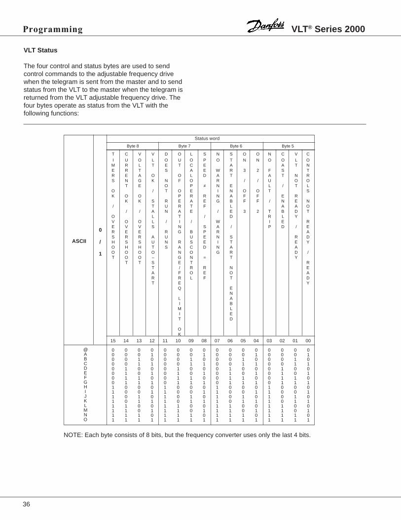
Status word
T C V V D O L S N S O O N C V CI U O L O U O P O T N N O O L OM R L T E T C E A A T NE R T S A E W R 3 2 F S TR E A O O L D A T A T N RS N G K N F O R / / U O O
T E O P ≠ N E L / T LO / T O E I N O O T SK O O P R R N A F F E R
K K S R E A E G B F F / N E N/ T U R T F L A A O
/ / A N A E / E 3 2 T B D TO L T / D R L YV O O L / I / W I E RE V V S N S A / P D / ER E E R G B P R AS R R A U U E N S R DH S S U N R S E I T E YO H H T S A C D N A AO O O O N O G R D /T O O – G N = T Y
T T S E T RT / R R N EA F O E O AR R L F T DT E Y
Q EN
L AI BM LI ET D
OK
ASCII
Byte 8 Byte 7 Byte 6 Byte 5
VLT Status
The four control and status bytes are used to sendcontrol commands to the adjustable frequency drivewhen the telegram is sent from the master and to sendstatus from the VLT to the master when the telegram isreturned from the VLT adjustable frequency drive. Thefour bytes operate as status from the VLT with thefollowing functions:
NOTE: Each byte consists of 8 bits, but the frequency converter uses only the last 4 bits.

37
VLT® Series 2000 Programming
@ABCDEFGHIJKLMNOP
0
/
1
15 14 13 12 11 10 09 08 07 06 05 04 03 02 01 00
0 0 0 0 0 0 0 0 0 0 0 0 0 0 0 00 0 0 1 0 0 0 1 0 0 0 1 0 0 0 10 0 1 0 0 0 1 0 0 0 1 0 0 0 1 00 0 1 1 0 0 1 1 0 0 1 1 0 0 1 10 1 0 0 0 1 0 0 0 1 0 0 0 1 0 00 1 0 1 0 1 0 1 0 1 0 1 0 1 0 10 1 1 0 0 1 1 0 0 1 1 0 0 1 1 00 1 1 1 0 1 1 1 0 1 1 1 0 1 1 11 0 0 0 1 0 0 0 1 0 0 0 1 0 0 01 0 0 1 1 0 0 1 1 0 0 1 1 0 0 11 0 1 0 1 0 1 0 1 0 1 0 1 0 1 01 0 1 1 1 0 1 1 1 0 1 1 1 0 1 11 1 0 0 1 1 0 0 1 1 0 0 1 1 0 01 1 0 1 1 1 0 1 1 1 0 1 1 1 0 11 1 1 0 1 1 1 0 1 1 1 0 1 1 1 01 1 1 1 1 1 1 1 1 1 1 1 1 1 1 1
ASCII
CONTROL WORD
Byte 8 Byte 7 Byte 6 Byte 5
N C C N N D J J N R H Q C O O O0 H H O O A O O O A O U O F F F
O O T G G M L I A F F FF I I F F A F P D C SU C C U U 2 1 U K T 3 2 1N E E N N N N S / -C C C O O O C T S / / / /T O O T T T F F T O R TI F F I I F F I P A O E O O OO O O V O M P N N N NN S S N N A / / N / P A/ E E L / B 3 2 1R T T / / I O O / S E LE - - D N N T N R EV U U C S R A A A DE P P A L / E R B MR T O S T L PS 2 1 C W V E EI H D A T DN - O LG U W I
P N D
NOTE: Each byte consists of 8 bits, but the frequency converter uses only the last 4 bits.
VLT Control Commands
The four control and status bytes are used to send controlcommands to the VLT adjustable frequency drive when thetelegram is sent from the master, and to send status fromthe VLT to the master when the telegram is returned fromthe VLT. When these four bytes are used for control, theyhave the following meaning:
OFF 1: Makes a normal ramp stop of the motor andopens the relay output of the VLT (relay off).
OFF 2: Makes a motor coast and opens the relay output(relay off)
OFF 3: Same as OFF 1, but the motor makes aquick-stop.
Bit 10: This bit has to be 1, if any of the control commandsshould cause a reaction.

38
★ = ROM default setting. Text in ( ) = display text. Figures in [ ] are used when communicating with the bus.
Programming VLT® Series 2000
Group 600 -- Service and Diagnostics
606 Total Operation Hours (TOTAL OP HRS)Description:
See parameter 610.
607 Running Hours (RUNNING HRS)Description:
See parameter 610.
608 Number of Power-ups (NO POWER)Description:
See parameter 610.
609 Number of Over-temperature (NO OVERTE)Description:
See parameter 610.
610 Number of Over-voltage (NO OVERVO)Description:
In formation stored by the VLT adjustable frequency drivefor later analysis.Parameter 606-607 are only updated every hour.
38
39
★ = ROM default setting. Text in ( ) = display text. Figures in [ ] are used when communicating with the bus.
VLT® Series 2000 Programming
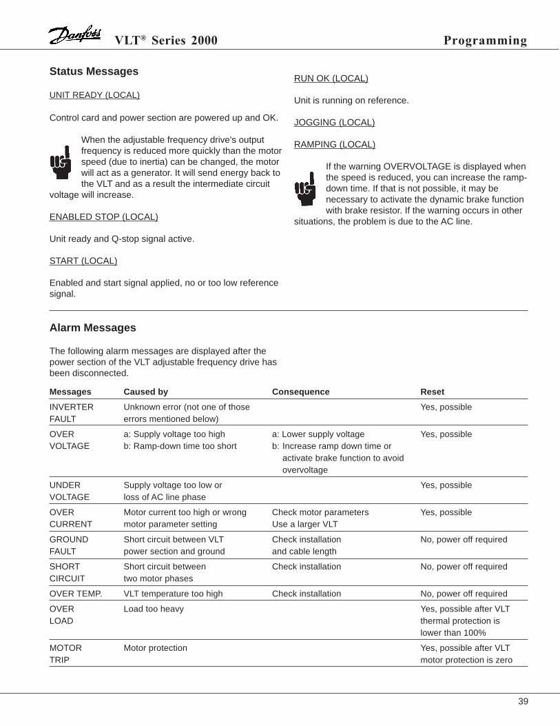
Status Messages
UNIT READY (LOCAL)
Control card and power section are powered up and OK.
When the adjustable frequency drive's outputfrequency is reduced more quickly than the motorspeed (due to inertia) can be changed, the motorwill act as a generator. It will send energy back tothe VLT and as a result the intermediate circuit
voltage will increase.
ENABLED STOP (LOCAL)
Unit ready and Q-stop signal active.
START (LOCAL)
Enabled and start signal applied, no or too low referencesignal.
Alarm Messages
The following alarm messages are displayed after thepower section of the VLT adjustable frequency drive hasbeen disconnected.
RUN OK (LOCAL)
Unit is running on reference.
JOGGING (LOCAL)
RAMPING (LOCAL)
If the warning OVERVOLTAGE is displayed whenthe speed is reduced, you can increase the ramp-down time. If that is not possible, it may benecessary to activate the dynamic brake functionwith brake resistor. If the warning occurs in other
situations, the problem is due to the AC line.
Messages Caused by Consequence Reset
INVERTER Unknown error (not one of those Yes, possibleFAULT errors mentioned below)
OVER a: Supply voltage too high a: Lower supply voltage Yes, possibleVOLTAGE b: Ramp-down time too short b: Increase ramp down time or
activate brake function to avoidovervoltage
UNDER Supply voltage too low or Yes, possibleVOLTAGE loss of AC line phase
OVER Motor current too high or wrong Check motor parameters Yes, possibleCURRENT motor parameter setting Use a larger VLT
GROUND Short circuit between VLT Check installation No, power off requiredFAULT power section and ground and cable length
SHORT Short circuit between Check installation No, power off requiredCIRCUIT two motor phases
OVER TEMP. VLT temperature too high Check installation No, power off required
OVER Load too heavy Yes, possible after VLTLOAD thermal protection is
lower than 100%
MOTOR Motor protection Yes, possible after VLTTRIP motor protection is zero
39

40
★ = ROM default setting. Text in ( ) = display text. Figures in [ ] are used when communicating with the bus.
Programming VLT® Series 2000
Warning Messages
Messages Caused by Consequence Reset
CURRENT LIMIT Over load VLT decreases speed - -
VOLTAGE HIGH Regenerative motor operation or The power section of the VLT - -supply voltage too high stops within 5 sec. - -
VOLTAGE LOW Missing phase or low supply The power section of the VLT - -stops within 5 sec.
INVERTER TIME Inverter overload At 98.2% load VLT displays the - -following warning:"INVERTER TIME"At 100% load:"ALARM OVERLOAD"
MOTOR TIME Motor overload VLT operates at least 60 sec. *) - -VLT operates between 100% and depending on the value of the - -
load before the power section ofthe VLT stops
LOW FRQ WARN Output frequency lower than the Depending on application - -value in parameter 210 Warning only
HI FRQ WARN Output frequency higher than the Depending on application - -value in parameter 211 Warning only
HI CUR WARN Motor current higher than the Depending on application - -value in parameter 213 Warning only
*) The time is reduced at a higher switch frequency.
Reset Messages
Messages Caused by Consequence Reset
AUTO START VLT tripped The VLT attempts to restart - -
TRIP Fault condition of the VLT or the The power section of the VLT Yesmotor stops
TRIP LOCKED Fault condition (over temp., short The power section of the VLT No, power oncircuit, ground fault) of the VLT stops Reset required
40

41
Appendix; Options
Appendix
1Ø / 3Ø (1 x 220-240 V / 3 x 208-240 V) 3Ø (3 x 208-240 V)VLT 2010 VLT 2015 VLT 2020 VLT 2030 VLT 2040 VLT 2050
EMC and motor coil module 195H6523 195H6524 195H6524 195H6525IP20 1-phase
EMC and motor coil module 195H6522 195H6522 195H6522 195H6522IP20 3-phase
EMC-filter module, IP20 (VBG-4) 195H6528 195H6528
Motor coil option, IP00 195H6510 195H6510 195H6510 195H6510
Motor coil option, IP10 (VGB-4) 195H6521 195H6521 195H6521 195H6521
LC and EMC filter module 195H6527 195H6526 195H6526 195H6526IP20 3-phaseMotor coil module IP20 195H6529 195H6529 195H6529 195H6529
3Ø (3 x 380-460 V)VLT 2020 VLT 2025 VLT 2030 VLT 2040 VLT 2050
EMC and motor coil module 195H6522 195H6522 195H6522 195H6522 195H6522IP20, (380-415 V only)
Motor coil option, IP10 (VGB-4) 195H6521 195H6521 195H6521 195H6521 195H6521
LC and EMC filter module 195H6527 195H6527 195H6527 195H6526 195H6526IP20
Motor coil module IP20 195H6529 195H6529 195H6529 195H6529 195H6529
195H6521, IP10
195H6510, IP00 195H6522, 195H6523, 195H6524, 195H6525,195H6526, 195H6527, 195H6528, 195H6529,IP20, Enclosure Module
VLT 2000/2000 PACK, Motor Coil and Filter Options
4.0(102)
3.0(75)
3.1(80)
5.1(130)
7.5(190)
6.3(160)
U1 V1 W1
PE
U2 V2 W2
PE
4.3(110)

42
Appendix; PI Regulation
Parameter 120:Controls the bandwidth of the output from PID controller.Set at 100%.
Parameter 121:Controls the gain of the system. For most fan and pumpsystems it should not be higher than 0.9. If set to highervalues the system may become unstable.• Centrifugal fans - between 0.1 - 0.6• Centrifugal pumps - between 0.3 - 0.8
Parameter 122:Improves the final accuracy by integrating out the error.• Centrifugal fans - between 10-12 seconds• Centrifugal pumps - between 3-8 seconds
Parameter 123:Differential time is not used in pump and fan systems.Set to Off.
Parameter 124:If the feedback signal is fluctuating it can be dampenedwith a time constant. This can occur on pump systemswhere the pipe can be shut off quickly and cause astanding wave of water.Set initially to 0 seconds.
Parameter 125:Leave at the default value of 100% unless thefollowing conditions occur.• If the feedback signal does not match the standard
analog signal choices in parameter 412 & 413 a valuemust be programmed which scales the feedback signalto a standard analog value.
• When using min. speed, parameter 201, it must beensured that the min. speed % value is not greater thanthe set-point % value, otherwise the min. speed willover-ride the set-point.
(See example on page 43.)
The following instructions will enable quick and easy set-up of the PI regulation and associated parametersettings. Detailed information about each parameter canbe found in the parameter section of this manual.
Parameter 100:Set the load type. There are several choices in eachgroup but variable torque medium or variable torquemedium with AEO will suit most pumps or fans.
Parameter 101:Select closed loop operation.
Parameter 114:Choose the type of feedback signal the transmitter isusing. The default value is current as it is the mostwidely used signal type.
Parameter 115 & 116:Are used to scale a display read-out which is proportionalto the feedback transmitter signal. The value is displayedonly if feedback has been selected in display mode. Toget to display mode from any other mode press MENU &DATA keys simultaneously.If a transmitter has a range of 0-5 bar, 0 can be set inparameter 115 and 5 in parameter 116. In parameter 117the unit bar can be programmed.The default values are 0 & 100, to display 0-100%.
Parameter 117:Choose the unit of measurement for scaling thefeedback signal of the transmitter set in parameter 115 &116. The default value is %.
Parameter 119:The feed forward factor allows a part of the set-pointsignal to by-pass the PID regulator. This gives fasterresponse when starting up a system where theintegration time (parameter 122) is very long, and thesystem error is small.Set at 0%. Only add 5% at a time, and only if the systemtakes a long time to start up. The drawing shows theinfluence of the feed forward.
Feedforward
Process
FBfactor
PID Me+
–
+
Feedback signal
Setpointor
Reference
(RampsP: 215, 216)
(P: 119)

43
Appendix; PI Regulation
Example:The set-point is 40%, and the min. speed is 50%.
1. Selecting a new set-point. Choose a value that willraise the set-point about 10% higher than the min.speed.New set-point = % min. speed x 1.1 = 55%
2. Setting parameter 125. Apply the same increase tothis parameter. 100 x 1.1 = 110%
Parameter 201:Set min. frequency if required.If you enter a min. speed you must observe the following:• When min. speed is used parameter 411 must be set
to "proportional with min. limit".• If the min. frequency % is higher than the set-point %
you must re-scale parameter 125 and the set-point.
Parameter 202:Max. frequency is normally set to 50 Hz. Runningcentrifugal pumps and fans above this speed will causeoverload of the pump or fan, as the power increases tothe third power of the speed change.
Example:If the speed increased to 60 Hz the power will increaseby a massive 173%.Set at 50 Hz.
Parameter 205:The internal set-point for the regulator.Enter the set-point % value.
Externally it can be one of the choices of the analogvalues. Use of one of the analog choices will prevent itsuse as the feedback signal.The use of the internal set-point reduces installationcosts. Up to 4 internal set-points (by using parameters205-208) can be selected by a combination of 2 switches.Refer to the instruction manual for further information.The set-point can be found by calculating the percentageof required signal from the transmitter range.
Example:A pressure transmitter has range of 0-10 bar. A set-pointof 4 bar is required.Set-point = 4/10 x 100 = 40%Enter 40 in parameter 205.
Parameter 214:Use only linear ramps.
Parameter 215 & 216:The ramps only function on starting and stopping thesystem.Enter the ramp up and down times in seconds.
Parameter 315:Set the motor thermal protection to trip 1 if thermalprotection of the motor is required.
Parameter 411:This parameter must be changed from its default valuewhen PID regulation is used.Set to "proportional with min. limit".
Parameter 412-413:Set the type of analog input signal for the set-pointand feedback signals. Parameter 114 has previously setup the selection of the feedback signal type.If parameter 205 (internal set-point) is used either currentor voltage can be used as the feedback signal.If one of the inputs is not used it must be set to nooperation.
Normal or Inverse Control
Introduction:The control is called normal, if the motor speed isincreased when the feedback signal goes down, and themotor speed is reduced if the feedback signal goes up.Typical for pump pressure systems and air handling unitsin variable air volume systems.The control is called inverse if the motor speed isincreased when the feedback signal is increased. Typicalfor pit pumping where: the faster the water flows into thepit, the faster the pump must pump out the water.

44
Appendix; PI Regulation
For inverse control; modification of the setpoint andfeedback signal is required.
Example:A transmitter has a 0-15 foot span equal to 0-20mA. ThePID set-point must be set at 12 feet for inverse control.
• Enter 20-0 mA in parameter 413. The normal signal infigure A is converted to an inverse signal as shown infigure B.
• Calculate the set point for inverse control.
Setpoint = 100 – (4/5 x 100) = 20%
It can be seen in figure C how the set point is calculated.
• If the internal set-point is used, ensure that parameter412 (voltage input) is set to no operation.
• The values in parameter 115 & 116 must be reversed.The display at min. feedback in parameter 115 becomesdisplay at max. feedback and parameter 116 becomesdisplay at min. feedback.
• Connections and set-up are identical to normal control.
0 12 15 Feet
Inverted signal from par:413 (current)where 12 ft. represents 100%-80%=20%
Figure C.
Setpoint = 20%
% Setpoint
100
External Setpoint
55
600/4-20 mA transmitterparameter 413 (0/4-20mA)
+
–
–+
External setpointusing potentiometer.1 kOhm wire wound.Parameter 412 (0-10V)
Link
VLT control terminals
12
27
16
18
50
53
55
Internal Setpoint
55
60 0/4-20 mA transmitterparameter 413 (0/4-20mA)
–+
Internal setpointparameter 205
Set parameter 412to (no operation)
LinkStart/StopParameter 402 (start)
VLT control terminals
12
27
16
18
50
53
55
Start/StopParameter 402 (start)
20
mA
Normal signal from transmitter where12 ft. represents 16mA (80%)
0 7.5 15 FtFigure A.
100
%
0 7.5 15 Ft
Figure B.
Inverted signal from par:413 12 ft. represents 100%-80%=20%

45
Appendix; PI Regulation
External Manual Control Over-rideIt is often necessary to run the machine manually formaintenance reasons.Manual control can be carried out manually from thekeypad of all the units.If remote control of the manual over-ride is requiredadditional circuitry is necessary.For the VLT Series 3500 special parameters are availablefor external manual over-ride. Refer to the VLT Series3500 instruction manual.
The following circuit and instructions for external manualover-ride relates to the VLT Series 3000. The proposedcontrol scheme is based on using 2 of the 4 menu set-ups. Menu set-up 1 has the parameters set for PIoperation and Menu set-up 2 has the parameters set formanual control.
1. Set parameter 001 to multi set-up.
2. Set parameter 400 to select set-up.
3. Install an "Auto-Manual" switch across terminals 12 &16. This will allow selection between the 2 menu set-ups. The bottom right hand corner of the display willshow the menu set-up you are in.
4. Program menu set-up 1 for PI operation.
5. Select menu set-up 2 and alter the followingparameters:
• Parameter 100; Set to the same load type as inmenu 1. You can check the parameter data in menu2 against the parameter data in menu 1 by switchingbetween menu set-ups while you are in thatparameter.
• Parameter 107-113; Set to the same load types asin menu 1.
• Parameter 201-201; Max. and Min. Frequency canbe set to suit manual control.
• Parameter 209; Set to the same load type as inmenu 1.
• Parameter 215-216; Set the ramp times to suit theapplication.
• Parameter 315; Set the motor thermal overloadprotection to trip 2.
• Parameter 412; Set to 0-10 V.
• Parameter 413; Set to no operation.
External Manual Control Over-ride
55
600/4-20 mA transmitterparameter 413 (0/4-20mA)
+
–
–+
Manual controlpotentiometer.1 kOhm wire wound.
LinkStart/StopPar: 402 (start)
VLT control terminals
NOTE: All control wiring needs to beshielded and the shield grounded tothe clamps as shown in the respectiveinstruction manuals.
12
27
16
18
50
53
55 InternalsetpointPar: 205
Auto Manual

VLT SERIES 2000 PARAMETER GROUPS AND FACTORY DEFAULT SETTINGS
OPERATION andDISPLAY:000 LANGUAGE SELECT S)
ENGLISH001 MENU SETUP SELECT S)
SETUP 1002 SETUP COPY
DO NOT COPY003 LOCAL REMOTE S)
REMOTE004 LOCAL REFERENCE S)
0 Hz005 DISPLAY VALUE S)
1000006 LOCAL RESET S)
ENABLE007 LOCAL START/STOP S)
ENABLE008 LOCAL REVERSING S)
DISABLE009 LOCAL JOGGING S)
ENABLE010 LOCAL SPEED
SELECT S)
ENABLE013 DATA CHANGE LOCK S)
NOT LOCKED
LOAD andMOTOR:101 SPEED CONTROL 2,S)
SLIP COMPENSATED102 CURRENT LIMIT CONT. S)
PROGRAMMED SET103 MOTOR POWER
NOMINAL SIZE104 MOTOR VOLTAGE
DEPENDING ON UNIT105 MOTOR FREQUENCY
DEPENDING ON UNIT107 MOTOR CURRENT 2, S)
DEPENDING ON UNIT108 MOTOR MAGNETIZE 2,S)
DEPENDING ON UNIT109 START VOLTAGE 2, S)
DEPENDING ON UNIT110 START COMP 2,S)
DEPENDING ON UNIT111 U/F RATIO 2,S)
DEPENDING ON UNIT112 SLIP COMP 2, S)
DEPENDING ON UNIT114 FEEDBACK SIGNAL S)
CURRENT 20mA119 FEED FWD FACTOR 2, S)
100%120 CONTROL RANGE 42 S)
100%121 PROPORTION GAIN 2, S)
0.01122 INTEGRAL TIME 2, S)
OFF125 FEEDBACK SCALING 2, S)
100%
REFERENCES andLIMITS:200 FREQUENCY RANGE
0-120 Hz201 MIN. FREQUENCY 2, S)
0.00 Hz202 MAX. FREQUENCY 2, S)
DEPENDING ON UNIT203 JOG FREQUENCY 2, S)
10204 DIGITAL REF. TYPE 2, S)
SUM205 DIGITAL REF. 1 2, S)
00.0206 DIGITAL REF. 2 2, S)
0207 DIGITAL REF. 3 2, S)
0208 DIGITAL REF. 4 2, S)
0209 CURRENT LIMIT 2, S)
DEPENDING ON UNIT210 WARN FREQ. LOW 2, S)
0211 WARN FREQ. HIGH 2, S)
fRANGE (from 200)213 WARN CURRNT HIGH 2,S)
IVLT MAX (from 209)215 RAMP-UP TIME 2, S)
5 SEC216 RAMP-DOWN TIME 2, S)
5 SEC218 QUICK-STOP RAMP
1 SEC224 CARRIER FREQ 2, S)
4.5230 SPEED UP/DOWN
DISABLE
FUNCTIONS andTIMERS:300 BRAKE FUNCTION S)
NOT APPLIED306 DC BRAKING TIME 2, S)
0307 DC BRAKE CUT-IN
FREQUENCY 2, S)
1308 DC BRAKE VOLTAGE 2, S)
10309 RESET MODE S)
MANUAL RESET310 TRIP DELAY AT
CURRENT LIMIT S)
INFINITE315 MOTOR THERMAL 2, S)
PROTECTIONOFF
INPUTS andOUTPUTS:402 TERMINAL 18 START S)
START403 TERMINAL 19
REVERSING S)
REVERSING404 TERMINAL 27 STOP S)
MOTOR COASTING405 TERMINAL 29 INPUT S)
JOG408 TERMINAL 46 OUTPUT S)
UNIT READYREMOTE CONTROL
409 TERMINAL 01RELAY OUTPUT S)
READY411 ANALOG REF. TYPE S)
LINEAR412 TERMINAL 53
ANALOG VOLTAGE 2, S)
0-10VDC413 TERMINAL 60
ANALOG I 2, S)
0-20 mA
SERIAL DATAINTERFACE:500 ADDRESS
1501 BAUD RATE
1.2 K502* DATA READ-OUT S)
503* COASTING S)
OR504* Q-STOP S)
OR505* DC BRAKE S)
OR506* START S)
OR507* DIRECTION S)
DIGITAL508* RESET S)
OR509* SET-UP SELECT S)
OR510* SPEED SELECT S)
OR511 BUS JOG 1 S)
10514 BUS BIT 4 S)
Q-STOP516 BUS REFERENCE S)
0517 STORE DATA VALUES S)
OFF
SERVICE andDIAGNOSTICS:606 TOTAL OPERATION
HOURS607 RUNNING HOURS
608 NUMBER OFPOWER UPS
609 NIMBER OVER-TEMP
610 NUMBER OFOVER-VOLTAGE
46
DISPLAY MODEREADOUTS:REFERENCE %FREQUENCY HzDISPLAY FEEDBACK "UNIT"CURRENT ATORQUE %POWER kWPOWER HPENERGY KWhOUTPUT VOLYAGE VDC VOLTAGE VMOTOR ETR value %INVERTER ETR value %
* NOTE: Menu 502 can only be selected from the bus.These values are read-only values.
The PC/PLC may prompt for a value from an index
between 0 and 19.
In parameters 503 to 510 you can choose to control
the VLT adjustable frequency drive via the control
unit's terminals (digitally) and or via the bus.
When using Logical and Bus values in parameters
503-510, the digital control terminals are either
dependent on or overruled by the bus commands.2) AVAILABLE IN BOTH SETUPSS) CAN BE CHANGED IN START MODE (RUNNING MOTOR)

REFERENCES & LIMITS:200
201
202
203
204
205
206
207
208
209
210
211
213
215
216
218
224
230
LOAD & MOTOR:101
102
103
104
105
107
108
109
110
111
112
114
119
120
121
122
125
FUNCTIONS & TIMERS:300
306
307
308
309
310
315
INPUTS & OUTPUTS:402
403
404
405
408
409
411
412
413
SERIAL DATA INTER.:500
501
502*
503*
504*
505*
506*
507*
508*
509*
510*
511
514
516
517
SERVICE & DIAG.:606
607
608
609
610
OPERATION & DISPLAY:000
001
002
003
004
005
006
007
008
009
010
013
47
CUSTOMER PARAMETER SETTINGS
* NOTE: Menu 502 can only be selected from the bus.These values are read-only values.
The PC/PLC may prompt for a value from an index
between 0 and 19.
In parameters 503 to 510 you can choose to control
the VLT adjustable frequency drive via the control
unit's terminals (digitally) and or via the bus.
When using Logical and Bus values in parameters
503-510, the digital control terminals are either
dependent on or overruled by the bus commands.