Vlt fc 300 operating instructions
42
VLT® AutomationDrive FC300 Operating Instructions Center Winder Controller MCO 352
-
Upload
toan-huynh -
Category
Technology
-
view
144 -
download
4
description
Tài liệu Biến Tần Vlt fc 300
Transcript of Vlt fc 300 operating instructions
VLT® AutomationDrive FC300
Operating Instructions
Center Winder ControllerMCO 352

Contents
1 How to Read these Operating Instructions 3
How to Read These Operating Instructions 3
Additional Literature for VLT AutomationDrive, MCO 305 and MCT 10 Motion Con-trol Tool 3
Approvals 3
Symbols 3
Abbreviations 4
2 Safety Instructions and General Warnings 5
High Voltage Warning 5
Safety Instructions 5
Before commencing repair work 5
Avoid Unintended Start 5
Safe Stop of VLT AutomationDrive FC302 6
General Warning 6
3 Introduction to Center Winder Controller 7
MCO 352 Center Winder Controller 7
Additional Features 8
System Requirements 9
4 How to Install 11
VLT AutomationDrive Terminals 11
Center Winder Option Terminals 12
Digital and Analog I/Os 13
Read-only Application Parameters 25
5 Center Winder Calibration 27
Frequency Converter Checkout 27
Preset Winder Function Parameters 28
Winder Scaling Factor Calibration – Open loop Speed Adjustments 29
Check Inputs 30
Calibration of Diameter Measurement Signal 30
Check Tension Correction Direction 31
Winder Closed Loop Calibration 31
6 Troubleshooting 33
7 Appendix 35
Center Winder Settings 35
MCO Basic Settings 36
Index 37
VLT® Center Winder MCO 352 Contents
MG.33.T1.02 - VLT® is a registered Danfoss trademark 1

1 How to Read these Operating Instructions VLT® Center Winder MCO 352
2 MG.33.T1.02 - VLT® is a registered Danfoss trademark
1
1 How to Read these Operating Instructions
1.1.1 How to Read These Operating Instructions
These Operating Instructions will help you get started, program, and troubleshoot your Center Winder Option. Please read these operating instructions
in full and, in order to be able to work with the system safely and professionally, particularly observe the hints and cautionary remarks.
Chapter How to Read these Operating Instructions introduces the manual and informs you about the approvals, symbols, and abbreviations used
in this literature.
Chapter Safety Instructions and General Warnings entails instructions on how to handle the Center Winder Controller correctly.
Chapter Introduction to Center Winder Controller informs you in general about center winders and different methods of rewinding and unwinding.
Chapter How to Install informs you how to start up the Center Winder Option. This section includes the description of the terminals and the parameters.
Chapter Center Winder Calibration informs how to calibrate the winder. Detailed instructions on how to proceed can be found in this section.
Chapter Troubleshooting assists you in solving problems that may occur when installing and using the Center Winder Controller.
Chapter Appendix provides information about parameters in clearly arranged lists. Please see the Parameter Reference in the MCO 305 Design Guide
for more details.
1.2.1 Additional Literature for VLT AutomationDrive, MCO 305 and MCT 10 Motion ControlTool
The MCO 305 Operating Instructions provide the necessary information for build-in, set-up, and optimize the controller.
The VLT AutomationDrive FC 300 Operating Instructions provide the necessary information for getting the drive up and running.
The VLT AutomationDrive FC 300 Design Guide entails all technical information about the drive and customer design and applications.
The VLT AutomationDrive FC 300 MCT 10 Operating Instructions provide information for installation and use of the software on a PC.
Danfoss Drives technical literature is also available online at www.danfoss.com/drives.
1.3.1 Approvals
1.4.1 Symbols
Symbols used in this Operating Instructions.
NB!
Indicates something to be noted by the reader.
Indicates a general warning.
VLT® Center Winder MCO 352 1 How to Read these Operating Instructions
MG.33.T1.02 - VLT® is a registered Danfoss trademark 3
1
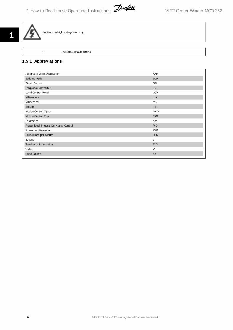
Indicates a high-voltage warning.
∗ Indicates default setting
1.5.1 Abbreviations
Automatic Motor Adaptation AMA
Build-up Ratio BUR
Direct Current DC
Frequency Converter FC
Local Control Panel LCP
Milliampere mA
Millisecond ms
Minute min
Motion Control Option MCO
Motion Control Tool MCT
Parameter par.
Proportional Integral Derivative Control PID
Pulses per Revolution PPR
Revolutions per Minute RPM
Second s
Tension limit detection TLD
Volts V
Quad Counts qc
1 How to Read these Operating Instructions VLT® Center Winder MCO 352
4 MG.33.T1.02 - VLT® is a registered Danfoss trademark
1
2 Safety Instructions and General Warnings
VLT Center Winder MCO352
Operating Instructions
Software version: 1.xx
These Operating Instructions can be used for the VLT Center Winder MCO352 with all FC 300 frequency converters with software version 4.9x.
The software version of FC 300 can be read in parameter 15-43.
2.2.1 High Voltage Warning
The voltage of the VLT AutomationDrive is dangerous whenever the converter is connected to mains. Incorrect fitting of the motor or the VLT Automa-
tionDrive may cause damage to the equipment, serious injury or death. Consequently, it is essential to comply with the instructions in this manual as well
as local and national rules and safety regulations.
2.2.2 Safety Instructions
• Make sure the VLT AutomationDrive is properly connected to earth.
• Do not remove mains plugs or motor plugs while the VLT AutomationDrive is connected to mains.
• Protect users against supply voltage.
• Protect the motor against overloading according to national and local regulations.
Motor overload protection is not included in the default settings. To add this function, set par. 1-90 Motor thermal protection to value ETR trip or ETR
warning.
For the North American market: ETR functions provide class 20 motor overload protection, in accordance with NEC.
The earth leakage current exceeds 3.5 mA.
The [OFF] key is not a safety switch. It does not disconnect the VLT AutomationDrive from mains.
2.2.3 Before commencing repair work
1. Disconnect VLT AutomationDrive from mains.
2. Disconnect DC bus terminals 88 and 89.
3. Wait at least 4 minutes.
4. Remove motor plugs.
2.2.4 Avoid Unintended Start
While VLT AutomationDrive is connected to mains, the motor can be started/stopped using digital commands, bus commands, references or via the LCP.
Disconnect the VLT AutomationDrive from mains whenever personal safety considerations make it necessary to avoid unintended start.
To avoid unintended start, always activate the [OFF] key before changing parameters. Unless terminal 37 is turned off, an electronic fault, temporary
overload, a fault in the mains supply, or lost motor connection may cause a stopped motor to start.
VLT® Center Winder MCO 352 2 Safety Instructions and General Warnings
MG.33.T1.02 - VLT® is a registered Danfoss trademark 5
2
2.2.5 Safe Stop of VLT AutomationDrive FC302
The VLT AutomationDrive FC 302 can perform the Designated Safety Function Uncontrolled Stopping by removal of power (as defined by draft IEC
61800-5-2) or Stop Category 0 (as defined in EN 60204-1). It is designed and approved suitable for the requirements of Safety Category 3 in EN 954-1.
This functionality is called Safe Stop. In order to install and use the Safe Stop function in accordance with the requirements of Safety Category 3 in EN
954-1, the related information and instructions of the VLT AutomationDrive FC 300 Design Guide MG.33.BX.YY must be followed! The information and
instructions of the Operating Instructions are not sufficient for a correct and safe use of the Safe Stop functionality!
2.2.6 General Warning
WARNING:
Touching the electrical parts may be fatal – even after the equipment has been disconnected from mains.
Also make sure that all voltage inputs have been disconnected, such as load-sharing (linkage of DC intermediate circuit), as well as the motor
connection for kinetic back-up.
Using VLT AutomationDrive FC 300 wait at least 15 minutes.
2 Safety Instructions and General Warnings VLT® Center Winder MCO 352
6 MG.33.T1.02 - VLT® is a registered Danfoss trademark
2
3 Introduction to Center Winder Controller
3.1.1 MCO 352 Center Winder Controller
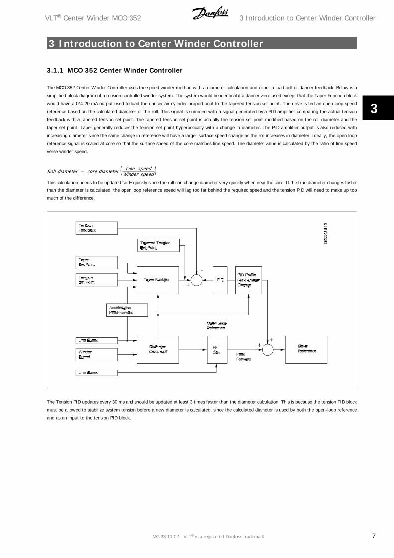
The MCO 352 Center Winder Controller uses the speed winder method with a diameter calculation and either a load cell or dancer feedback. Below is a
simplified block diagram of a tension controlled winder system. The system would be identical if a dancer were used except that the Taper Function block
would have a 0/4-20 mA output used to load the dancer air cylinder proportional to the tapered tension set point. The drive is fed an open loop speed
reference based on the calculated diameter of the roll. This signal is summed with a signal generated by a PID amplifier comparing the actual tension
feedback with a tapered tension set point. The tapered tension set point is actually the tension set point modified based on the roll diameter and the
taper set point. Taper generally reduces the tension set point hyperbolically with a change in diameter. The PID amplifier output is also reduced with
increasing diameter since the same change in reference will have a larger surface speed change as the roll increases in diameter. Ideally, the open loop
reference signal is scaled at core so that the surface speed of the core matches line speed. The diameter value is calculated by the ratio of line speed
verse winder speed.
Roll diameter = core diameter ( Line speedWinder speed )
This calculation needs to be updated fairly quickly since the roll can change diameter very quickly when near the core. If the true diameter changes faster
than the diameter is calculated, the open loop reference speed will lag too far behind the required speed and the tension PID will need to make up too
much of the difference.
The Tension PID updates every 30 ms and should be updated at least 3 times faster than the diameter calculation. This is because the tension PID block
must be allowed to stabilize system tension before a new diameter is calculated, since the calculated diameter is used by both the open-loop reference
and as an input to the tension PID block.
VLT® Center Winder MCO 352 3 Introduction to Center Winder Controller
MG.33.T1.02 - VLT® is a registered Danfoss trademark 7
3
3.1.2 Additional Features
Several features have been included to increase the overall stability of the winder and to increase control and monitoring of the winding process.
• Acceleration Feed-Forward: The Winder block diagram includes an acceleration feed-forward function that allows a shift in the tension/taper set
point based on changes in line speed. This provides a tension boost during initial acceleration to help compensate for system inertia.
• Tension-Taper Set-Point Ramp: The tapered tension set point generator will integrate any changes to the tension or taper set points over multiple
program scans. A parameter is provided to increase or decrease response time.
• Diameter Calculator Limiter: The diameter calculator includes a similar integration technique. A maximum rate of diameter change can be
adjusted by parameter. In addition, the calculated diameter is restricted from moving in the wrong direction to only 20 % of the rate applied to
the expected change in diameter. For example, if the station is rewinding a roll, the diameter is not expected to reduce in diameter.
• Diameter Calculator Minimum Speed: There is also a minimum speed requirement to enable the diameter calculator. At low speeds, the line and
winder speeds may not have enough resolution to accurately calculate diameter. A parameter is provided to define a minimum line speed required
for the diameter calculator to function. Until that speed is reached, the diameter value will not change.
• Programmable Analog Inputs: The VLT AutomationDrive has two analog inputs. Inputs 53 and 54 are analog inputs with a voltage range of ±10
VDC or a current range of 0/4-20mA. Use DIP-switch S201/S202 to select configuration. The source of the tension and taper set-points can be
adjusted by either analog input or parameter setting. The tension feedback and initial diameter measurement can only use analog inputs.
Parameters are provided to select the source of each input. Care must be taken not to program a single input for more than one function.
• Initial Diameter Measurement: In many winding applications there are very few variations in starting core diameter or initial roll size. A choice
of three programmable starting diameters can be programmed and logically selected. For applications where the starting diameter can vary
regularly, the Winder will allow the initial diameter to be measured through an analog input signal. Scaling parameters are provided to set the
analog level at core and at full roll. This function assumes a linear change in the diameter measurement signal.
• End of Roll Detection: An output is provided to indicate a diameter limit. For rewinding applications, the diameter limit occurs when the calculated
diameter exceeds a set limit. For unwinding applications, the diameter limit occurs when the calculated diameter is less than the set limit. The
station will continue to run after a diameter limit is detected. This output can be used to stop the line for a roll change.
• Tension Limit Detector: The Winder includes a tension limit detection (TLD) feature. This feature allows the Winder to trip if a low-tension or
high-tension feedback exists for a period of time. The trip delay includes a normal running delay as well as a secondary starting delay.
3 Introduction to Center Winder Controller VLT® Center Winder MCO 352
8 MG.33.T1.02 - VLT® is a registered Danfoss trademark
3
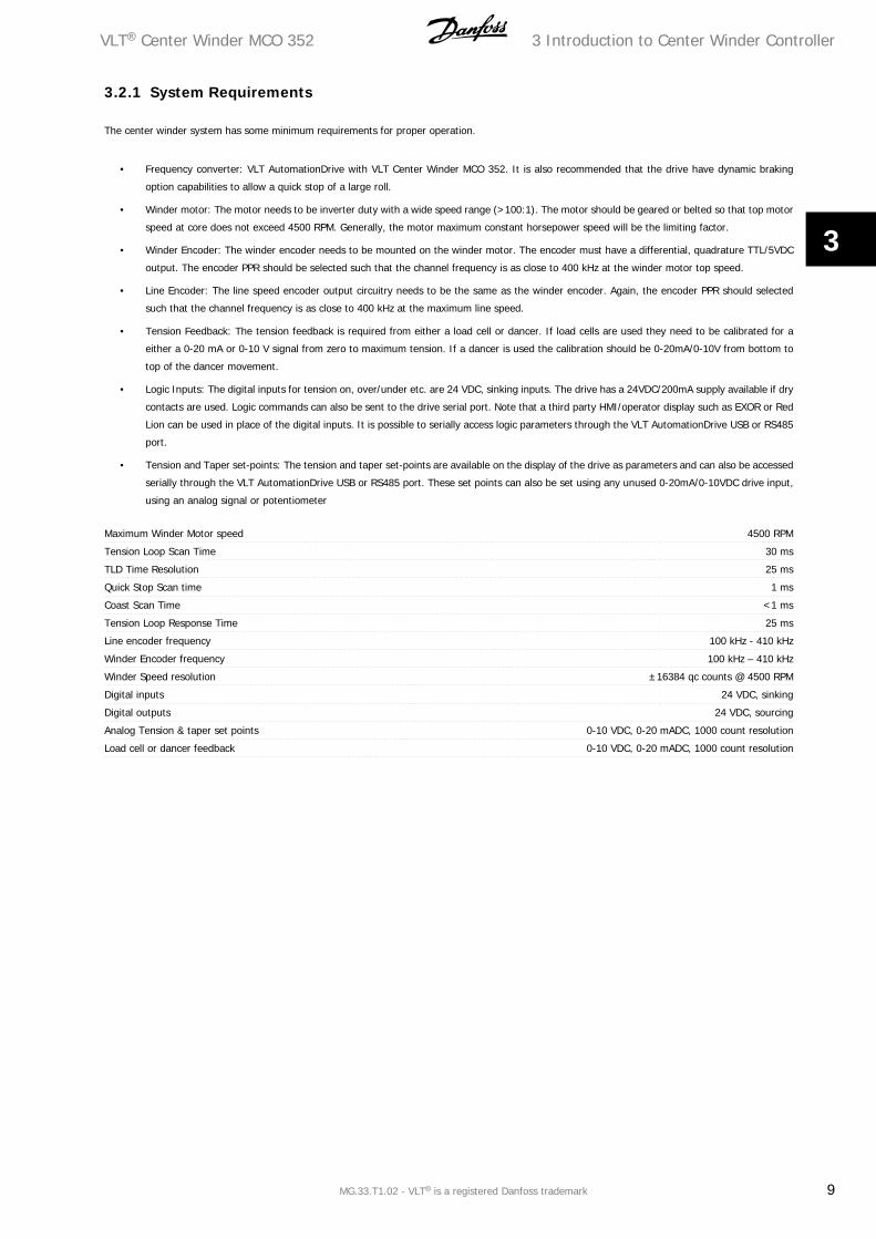
3.2.1 System Requirements
The center winder system has some minimum requirements for proper operation.
• Frequency converter: VLT AutomationDrive with VLT Center Winder MCO 352. It is also recommended that the drive have dynamic braking
option capabilities to allow a quick stop of a large roll.
• Winder motor: The motor needs to be inverter duty with a wide speed range (>100:1). The motor should be geared or belted so that top motor
speed at core does not exceed 4500 RPM. Generally, the motor maximum constant horsepower speed will be the limiting factor.
• Winder Encoder: The winder encoder needs to be mounted on the winder motor. The encoder must have a differential, quadrature TTL/5VDC
output. The encoder PPR should be selected such that the channel frequency is as close to 400 kHz at the winder motor top speed.
• Line Encoder: The line speed encoder output circuitry needs to be the same as the winder encoder. Again, the encoder PPR should selected
such that the channel frequency is as close to 400 kHz at the maximum line speed.
• Tension Feedback: The tension feedback is required from either a load cell or dancer. If load cells are used they need to be calibrated for a
either a 0-20 mA or 0-10 V signal from zero to maximum tension. If a dancer is used the calibration should be 0-20mA/0-10V from bottom to
top of the dancer movement.
• Logic Inputs: The digital inputs for tension on, over/under etc. are 24 VDC, sinking inputs. The drive has a 24VDC/200mA supply available if dry
contacts are used. Logic commands can also be sent to the drive serial port. Note that a third party HMI/operator display such as EXOR or Red
Lion can be used in place of the digital inputs. It is possible to serially access logic parameters through the VLT AutomationDrive USB or RS485
port.
• Tension and Taper set-points: The tension and taper set-points are available on the display of the drive as parameters and can also be accessed
serially through the VLT AutomationDrive USB or RS485 port. These set points can also be set using any unused 0-20mA/0-10VDC drive input,
using an analog signal or potentiometer
Maximum Winder Motor speed 4500 RPM
Tension Loop Scan Time 30 ms
TLD Time Resolution 25 ms
Quick Stop Scan time 1 ms
Coast Scan Time <1 ms
Tension Loop Response Time 25 ms
Line encoder frequency 100 kHz - 410 kHz
Winder Encoder frequency 100 kHz – 410 kHz
Winder Speed resolution ±16384 qc counts @ 4500 RPM
Digital inputs 24 VDC, sinking
Digital outputs 24 VDC, sourcing
Analog Tension & taper set points 0-10 VDC, 0-20 mADC, 1000 count resolution
Load cell or dancer feedback 0-10 VDC, 0-20 mADC, 1000 count resolution
VLT® Center Winder MCO 352 3 Introduction to Center Winder Controller
MG.33.T1.02 - VLT® is a registered Danfoss trademark 9
3

4 How to Install VLT® Center Winder MCO 352
10 MG.33.T1.02 - VLT® is a registered Danfoss trademark
4
4 How to Install
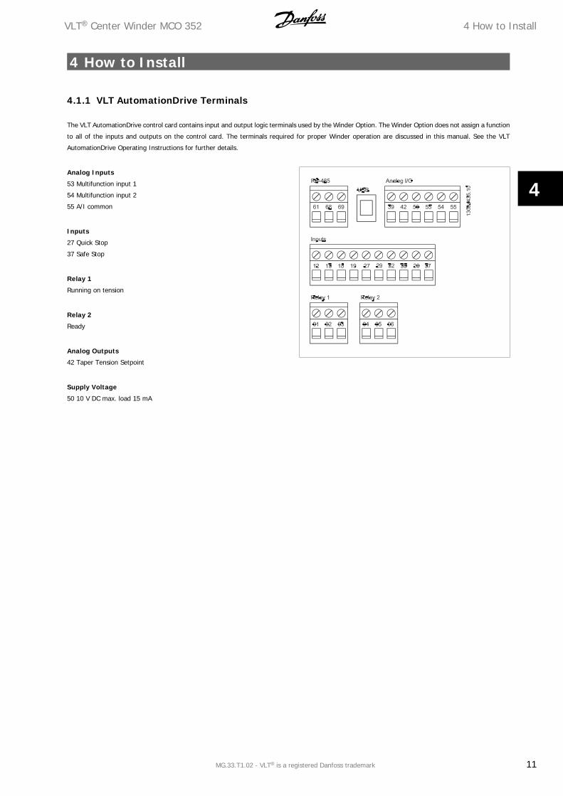
4.1.1 VLT AutomationDrive Terminals
The VLT AutomationDrive control card contains input and output logic terminals used by the Winder Option. The Winder Option does not assign a function
to all of the inputs and outputs on the control card. The terminals required for proper Winder operation are discussed in this manual. See the VLT
AutomationDrive Operating Instructions for further details.
Analog Inputs
53 Multifunction input 1
54 Multifunction input 2
55 A/I common
Inputs
27 Quick Stop
37 Safe Stop
Relay 1
Running on tension
Relay 2
Ready
Analog Outputs
42 Taper Tension Setpoint
Supply Voltage
50 10 V DC max. load 15 mA
VLT® Center Winder MCO 352 4 How to Install
MG.33.T1.02 - VLT® is a registered Danfoss trademark 11
4
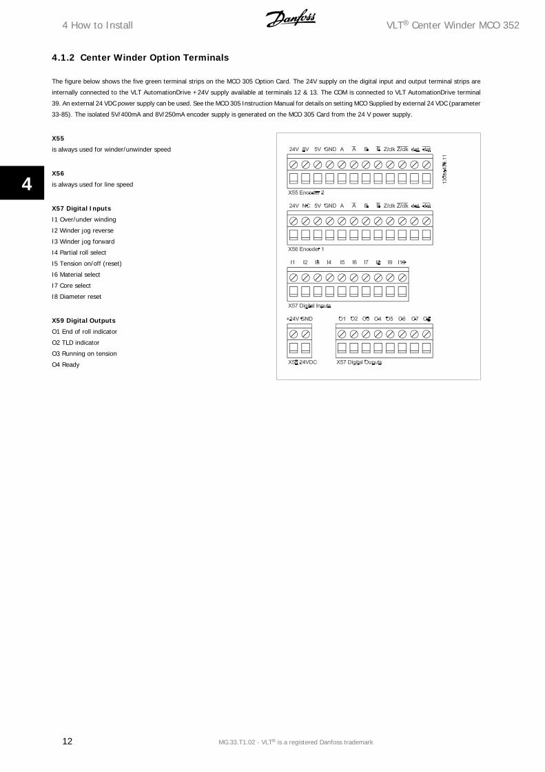
4.1.2 Center Winder Option Terminals
The figure below shows the five green terminal strips on the MCO 305 Option Card. The 24V supply on the digital input and output terminal strips are
internally connected to the VLT AutomationDrive +24V supply available at terminals 12 & 13. The COM is connected to VLT AutomationDrive terminal
39. An external 24 VDC power supply can be used. See the MCO 305 Instruction Manual for details on setting MCO Supplied by external 24 VDC (parameter
33-85). The isolated 5V/400mA and 8V/250mA encoder supply is generated on the MCO 305 Card from the 24 V power supply.
X55
is always used for winder/unwinder speed
X56
is always used for line speed
X57 Digital Inputs
I1 Over/under winding
I2 Winder jog reverse
I3 Winder jog forward
I4 Partial roll select
I5 Tension on/off (reset)
I6 Material select
I7 Core select
I8 Diameter reset
X59 Digital Outputs
O1 End of roll indicator
O2 TLD indicator
O3 Running on tension
O4 Ready
4 How to Install VLT® Center Winder MCO 352
12 MG.33.T1.02 - VLT® is a registered Danfoss trademark
4
4.2 Digital and Analog I/Os
4.2.1 MCO 352 I/O
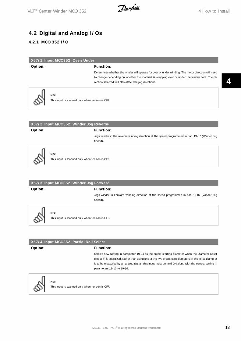
X57/1 Input MCO352 Over/Under
Option: Function:Determines whether the winder will operate for over or under winding. The motor direction will need
to change depending on whether the material is wrapping over or under the winder core. The di-
rection selected will also affect the jog directions.
NB!
This input is scanned only when tension is OFF.
X57/2 Input MCO352 Winder Jog Reverse
Option: Function:Jogs winder in the reverse winding direction at the speed programmed in par. 19-07 (Winder Jog
Speed).
NB!
This input is scanned only when tension is OFF.
X57/3 Input MCO352 Winder Jog Forward
Option: Function:Jogs winder in Forward winding direction at the speed programmed in par. 19-07 (Winder Jog
Speed).
NB!
This input is scanned only when tension is OFF.
X57/4 Input MCO352 Partial Roll Select
Option: Function:Selects new setting in parameter 19-04 as the preset starting diameter when the Diameter Reset
(Input 8) is energized, rather than using one of the two preset core diameters. If the initial diameter
is to be measured by an analog signal, this input must be held ON along with the correct setting in
parameters 19-13 to 19-16.
NB!
This input is scanned only when tension is OFF.
VLT® Center Winder MCO 352 4 How to Install
MG.33.T1.02 - VLT® is a registered Danfoss trademark 13
4
X57/5 Input MCO352 Tension On/Off (Reset)
Option: Function:Turns the tension controller ON and OFF. This input should be energized while the line is at zero
speed. The core will be released when this input is not energized. This input is also used to reset
fault conditions.
X57/6 Input MCO352 Material Select
Option: Function:Selects the Material Type (PAPER/POLY). Different material types such as paper verses poly require
different Tension loop PID settings and Speed loop proportional gain settings. Changing this input
toggles the values in parameters 19-41 to 19-50. If the PID parameter values are changed this input
must be switch to initiate saving the new values.
NB!
This input is scanned only when tension is OFF and when the material selection is to be made by digital input (see par. 19-23).
X57/7 Input MCO352 Core Select
Option: Function:Selects one of two preset core sizes set in parameters 19-05 and 19-06. Core 1 = OFF, Core 2 =
ON. This input is checked when the Diameter Reset (Input 8) in energized and the partial roll select
(Input 4) is not energized. If unwinding, Core 2 can be used as an alternate initial roll diameter, but
Core 1 must always be set for the smallest core diameter used.
NB!
This input is scanned only when tension is OFF.
X57/8 Input MCO352 Diameter Reset
Option: Function:Resets diameter to a new value. If the New Diameter Set (Input 4) is energized, the partial core
diameter value set in parameter 19-04 is used, otherwise the diameter is reset to core1 or core2
values based on Core Select (Input 7).
NB!
This input is scanned only when tension is OFF.
4.2.2 VLT I/O
Input 27 Quick Stop
Option: Function:Terminal 27 must be closed for the drive to run. If this input is opened while running, the frequency
converter will ramp to a stop at a rate set by the Quick Stop Deceleration time (parameter 3-81).
4 How to Install VLT® Center Winder MCO 352
14 MG.33.T1.02 - VLT® is a registered Danfoss trademark
4
Input 37 Safe Stop
Option: Function:Terminal 37 must be closed for the frequency converter to run. If this input is opened while running
the frequency converter will coast to a stop.
Output O1 End of Roll Indicator
Option: Function:This output turns ON to indicate that the diameter has reached the value programmed in parameter
19-12. This output turns OFF when Diameter is reset (Input 8) to a value in normal operating range.
Output O2 TLD Indicator
Option: Function:This output is turned ON when the Tension Limit Detector has sensed that tension has been out of
range as set in parameters 19-08 and 19-09 for the number of scans set in parameter 19-10. A
Tension Limit results in a Winder fault. Turning the tension OFF resets this fault and the output.
Output O3 Running on Tension
Option: Function:This output is turned ON when the winder is regulating tension. The output is turned OFF when
tension is switched off or if there is a station fault. Turning the tension OFF resets this fault and the
output.
Output O4 Ready
Option: Function:This output is turned ON when the station is ready to run. The output turns OFF if there is a TLD
fault, an FC Alarm, an MCO 305 Error, Commanded Quick Stop, or Commanded Coast. Note: Outputs
5-8 are not used.
Relay 01 Running on Tension
Option: Function:This relay output (01, 02, 03) is energized when the winder is regulating tension. The relay output
is de-energized when tension is switched off or if there is a station fault.
NB!
Parameter 5-40 must be set for MCO controlled [51] for this function to work as described.
Relay 02 Ready
Option: Function:This relay output (04, 05, 06) is energized when the station is ready to run. The relay will de-energize
on a TLD fault, an FC Alarm, an MCO 305 Error, Quick Stop, or Coast.
VLT® Center Winder MCO 352 4 How to Install
MG.33.T1.02 - VLT® is a registered Danfoss trademark 15
4
NB!
Parameter 5-40 must be set for MCO controlled (51) for this function to work as described.
4.2.3 Analog Inputs
Parameters 19-14, 19-19 to 19-21 allow setting the two analog inputs from the VLT AutomationDrive for any of the following.
• Tension Set Point
• Taper Set Point
• Tension Feedback
• Initial Diameter measurement
Input 53 Multi-function Input 1
Option: Function:This analog input functions according to the setting of parameter 19-19 to 19-21. Use DIP-switch
S201 to select a current (0-20 mA) or a voltage (-10 V to 10 V) configuration.
Input 54 Multi-function Input 2
Option: Function:This analog input functions according to the setting of parameter 19-19 – 19-21. Use DIP-switch
S201 to select a current (0-20mA) or a voltage (-10 V to 10 V) configuration.
Terminal 55 Analog Input Common
Option: Function:This terminal is the common for the two analog inputs 53/54.
Terminal 50 Analog Input +10V Out
Option: Function:This terminal is a supply of +10V/30 mA for the analog inputs.
Output 42 Tapered Tension Set-Point
Option: Function:When a Dancer system is used, the calculated Tapered Tension Set Point should control the loading
of the dancer air cylinder. This 0/4-20mA output can be used as input for the I-P transducer regu-
lating the load on the dancer air cylinder. Parameter 6-50 must be set for either OPTION 0-20 mA
or OPTION 4-20 mA.
NB!
If using a dancer, the Taper set point will have no affect if this output is not used to control the dancer air cylinder.
Terminal 39 Analog Output Common
Option: Function:This terminal is used as a common for the analog output signals.
4 How to Install VLT® Center Winder MCO 352
16 MG.33.T1.02 - VLT® is a registered Danfoss trademark
4
4.3.1 Parameters
19-01 Winder Mode Selection
Option: Function:Sets the station as either a rewinder or unwinder.
[0] * Rewinder
[1] Unwinder
19-02 Tension Set-Point
Range: Function:0 [0-1000]
1000 = 100.0% of full tension. Full tension is the point at which the load cell or dancer produces
a 20 mA or 10 V signal.
Sets the desired running tension. Note that the taper setting will affect the actual tension on the
web. If a dancer system is used, this value sets the dancer running position which would normally
be 500 or center of movement. This parameter is only active if par. 19-19 is set to 0.
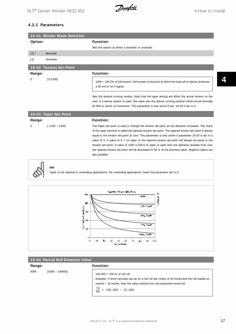
19-03 Taper Set-Point
Range: Function:0 [-1100 – 1100] The Taper set-point is used to change the tension set-point as the diameter increases. The result
of the taper function is called the tapered tension set-point. The tapered tension set-point is always
equal to the tension set-point at core. This parameter is only active if parameter 19-20 is set to a
value of 0. A value of 0 = no taper or the tapered tension set-point will always be equal to the
tension set-point. A value of 1000 is 100.0 % taper or each time the diameter doubles from core
the tapered tension set-point will be decreased to 50 % of the previous value. Negative tapers are
also possible.
NB!
Taper is not required in unwinding applications. For unwinding applications, leave this parameter set to 0.
19-04 Partial Roll Diameter Value
Range: Function:5000 [5000 – 100000]
100,000 = 100 % of full roll.
Example: If drive has been set-up for a full roll dia¬meter of 40 inches and the roll loaded on
rewind = 10 inches, then the value entered into this parameter would be
1040 × 100, 000 = 25, 000
VLT® Center Winder MCO 352 4 How to Install
MG.33.T1.02 - VLT® is a registered Danfoss trademark 17
4
This parameter is intended to preset the diameter when a partial roll is loaded on the rewinder. If
Input 4 is ON when the diameter is reset with Input 8, the diameter will be preset to the value
programmed in this parameter. For unwinding applications, this parameter can be used to set the
full roll diameter.
19-05 Core1 Diameter
Range: Function:5000* [5000 – 100000]
100000 = 100 % of full roll, see parameter 19-04.
This parameter is programmed with the main core value to be used on the winder. This parameter
must be set for the smallest core diameter for both rewind and unwind applications.
NB!
Note: Parameter 19-05 must be less than parameter 19-06.
19-06 Core2 Diameter
Range: Function:5000* [5000 – 100000]
100000 = 100 % of full roll, see Parameter 19-04.
This parameter allows programming a secondary core diameter if rewinding or a secondary full roll
diameter if unwinding.
NB!
Parameter 19-05 must be less than parameter 19-06.
19-07 Winder Jog Speed
Range: Function:0%* [0 – 100%]
Winder jog speed 100 = 100 % of the speed set in parameter 3-03 (MAX REFERENCE RPM).
This parameter sets the winder jog speed percentage. This speed is used for both forward and
reverse jogging. The jog ramp is fixed at 4 seconds.
NB!
Diameter is not taken into account to determine surface jog speed.
19-08 TLD Low Limit
Range: Function:0* [-200 – 2000]
1000 = 100.0 % tension.
This parameter is the low limit for the Tension Limit Detector.
NB!
Setting the value to -200 will disable the low tension limit trip.
4 How to Install VLT® Center Winder MCO 352
18 MG.33.T1.02 - VLT® is a registered Danfoss trademark
4
NB!
If the tension detection reaches the TLD Low Limit for more than TLD Timer (par. 19-10), output 2 is turned on and a trip is forced.
19-09 TLD High Limit
Range: Function:0* [0 – 2200]
1000 = 100.0 % tension.
This parameter is the high limit for the Tension Limit Detector.
NB!
Setting the value to 2200 will disable the high tension limit trip.
NB!
If the tension detection reaches the TLD High Limit for more than TLD Timer (par. 19-10), output 2 is turned on and a trip is forced.
19-10 TLD Timer
Range: Function:1* [1 – 200]
Each program scan is approx 25 ms.
Sets the number of consecutive program scans that the tension must exceed the high or low tension
limit before the Tension Limit Output will be energized and the station coasts to a stop. This function
is only active when tension is on.
19-11 TLD on Delay
Range: Function:0* [-500 – 0]
Each program scan is approx 25 ms.
When tension is first turned on, the tension limit timer can be preset to a negative value to allow
time for the winder to stabilize web tension. As soon as the tension moves within the low and high
tension limits, the TLD function begins operating normally. This function can be useful during a quick
machine start with a slack web. This function is only active when tension is on.
19-12 Diameter Limit Detector
Range: Function:0* [-100 – 100000]
100,000 = 100 % of full roll
When the calculated roll diameter reaches the set diameter, digital output 1 will turn ON to indicate
the end of the roll. This indicates a full roll when rewinding and an empty roll when unwinding.
NB!
The station will not stop automatically when the end of roll is detected.
VLT® Center Winder MCO 352 4 How to Install
MG.33.T1.02 - VLT® is a registered Danfoss trademark 19
4
19-13 Initial Diameter Measurement
Option: Function:It is possible to connect a roll diameter sensor to one of the frequency converter's analog inputs.
This signal can be used to have the controller use a measured initial diameter, rather than a diameter
size set by parameter. This is particularly useful in applications where non-uniform roll sizes are the
norm.
[0] * Set diameter when diameter reset Parameters 19-04 to 19-06 set the diameter when the diameter is reset.
[1] Set diameter based on analog signal The frequency converter sets the diameter based on an analog signal. The diameter can only be
reset when the tension is OFF.
19-14 Diameter Measurement Input
Option: Function:This parameter sets the analog input used for diameter measurement.
[1] Input 53 (0-10 VDC or 0-20 mA)
[2] Input 54 (0-10 VDC or 0-20 mA)
19-15 Reading at Core
Range: Function:0* [-1100 – 1100]
If a signal of 1.50 V results from measuring the smallest core, set this parameter to 150.
This parameter sets the analog input signal reading at the smallest core used. The value needs to
be multiplied by 100 to allow maximum resolution.
19-16 Reading at Full Roll
Range: Function:0 [-1111 – 2111]
If a signal of 9.50 V results from measuring the full roll, set this parameter to 950.
This parameter sets the analog input signal reading at the largest roll size used. The value needs
to be multiplied by 100 to allow maximum resolution.
19-19 Tension Set-Point Input
Option: Function:This parameter sets the source of the tension set-point.
[0] * Parameter 19-02
[1] Input 53 (0-10 VDC or 0-20 mA)
[2] Input 54 (0-10 VDC or 0-20 mA)
19-20 Taper Set-Point Input
Option: Function:This parameter sets the source of the taper set-point.
[0] * Parameter 19-03
[1] Input 53 (0-10VDC or 0-20mA)
[2] Input 54 (0-10VDC or 0-20mA)
19-21 Tension Feedback Input
Option: Function:Sets analog input used for tension feedback.
[1] * Input 53 (0-10 VDC or 0-20 mA)
[2] Input 54 (0-10 VDC or 0-20 mA)
4 How to Install VLT® Center Winder MCO 352
20 MG.33.T1.02 - VLT® is a registered Danfoss trademark
4
19-22 Tension Feedback Type
Option: Function:Selects type of tension feedback device.
[0] * Load cell
[1] Dancer
19-23 Command Source
Option: Function:Determines if the digital inputs 1-8 are to be active or parameters 19-61 through 19-68 are used
for these functions. When a third party display is used to control these functions, changing a pa-
rameter is the most efficient method.
[1] * Par. 19-61 to 19-68 for controlling Entered for the parameters 19-61 through 19-68 to control the functions.
[2] Digital input control Entered for digital input control.
19-24 Line Speed Scale
Range: Function:200* [200 – 18000]
Display value:
par. 19 − 24 − (max. Line encoder) Hz × 450
Scales line speed for 100,000 counts at max speed. These counts can be read in parameter 19-96.
19-25 Speed Match Scale
Range: Function:500* [500 – 10000] Matches surface speeds of line and winder at core while running line at 100 % speed.
19-26 Winder Speed Scale
Range: Function:200* [200 – 18000]
Display value:
par. 19 − 26 − (max. Winder encoder) Hz × 450
Scales winder speed for 100,000 counts at max speed. These counts can be read in par. 19-95.
19-27 Diameter Accel Rate
Range: Function:1* [1 – 50] Sets amount of changes allowed for the diameter in each program scan. This setting depends on
maximum material thickness and max line speed at core. The diameter change is scaled based on
100,000 = 100%.
Description of display value (calculation example):
Max . core speed = 10 revs
Material thickness = 0.01 inches
Roll diameter = 25 inches
Scan time = 25 ms
CountsScan = (10 rev
s )( 0.01 inchrev )( 100000 counts
25 inches )( 25msscan )
Max . countsscan = 10
NB!
If the diameter can vary from the selected reset value, a larger value will allow the calculator diameter to move more quickly to the
correct value.
VLT® Center Winder MCO 352 4 How to Install
MG.33.T1.02 - VLT® is a registered Danfoss trademark 21
4
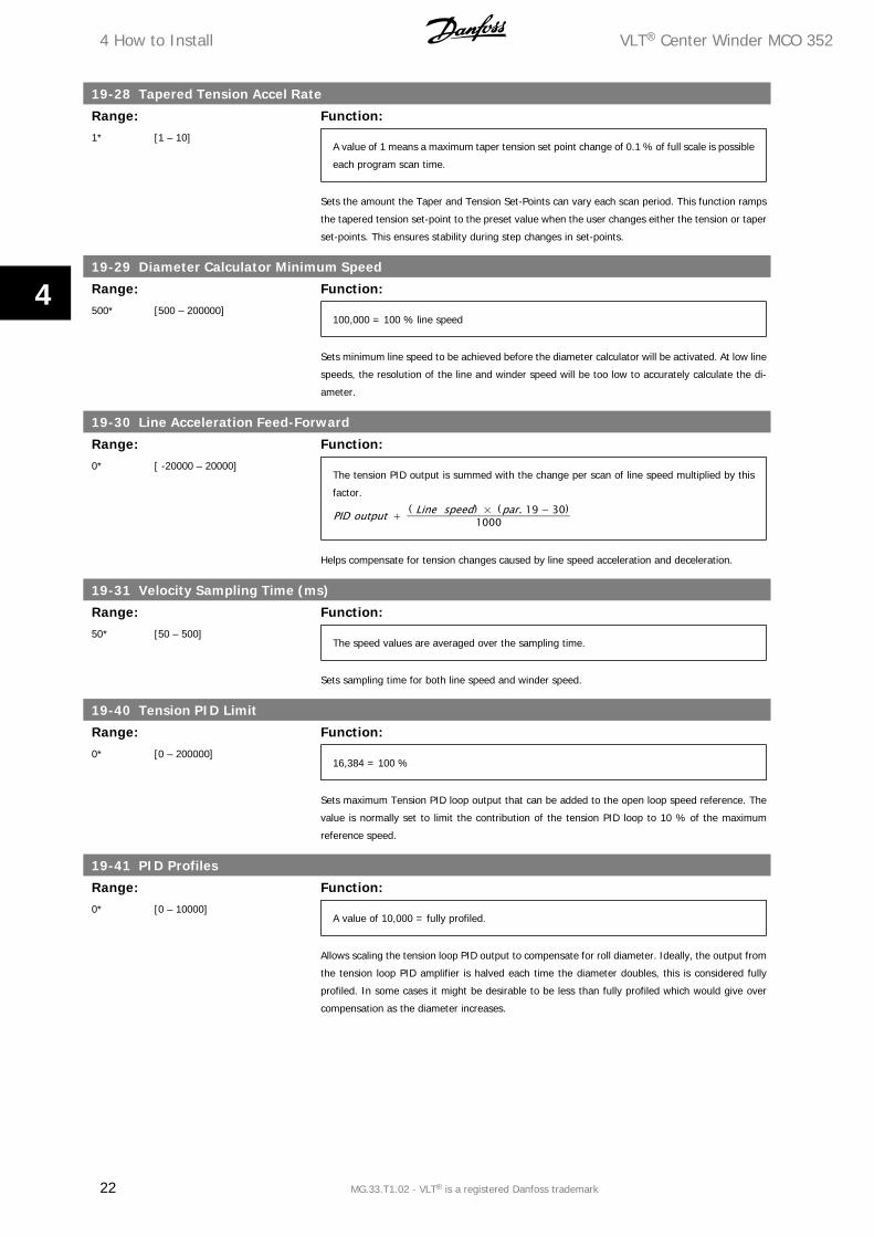
19-28 Tapered Tension Accel Rate
Range: Function:1* [1 – 10]
A value of 1 means a maximum taper tension set point change of 0.1 % of full scale is possible
each program scan time.
Sets the amount the Taper and Tension Set-Points can vary each scan period. This function ramps
the tapered tension set-point to the preset value when the user changes either the tension or taper
set-points. This ensures stability during step changes in set-points.
19-29 Diameter Calculator Minimum Speed
Range: Function:500* [500 – 200000]
100,000 = 100 % line speed
Sets minimum line speed to be achieved before the diameter calculator will be activated. At low line
speeds, the resolution of the line and winder speed will be too low to accurately calculate the di-
ameter.
19-30 Line Acceleration Feed-Forward
Range: Function:0* [ -20000 – 20000]
The tension PID output is summed with the change per scan of line speed multiplied by this
factor.
PID output + ( Line speed) × (par. 19 − 30)1000
Helps compensate for tension changes caused by line speed acceleration and deceleration.
19-31 Velocity Sampling Time (ms)
Range: Function:50* [50 – 500]
The speed values are averaged over the sampling time.
Sets sampling time for both line speed and winder speed.
19-40 Tension PID Limit
Range: Function:0* [0 – 200000]
16,384 = 100 %
Sets maximum Tension PID loop output that can be added to the open loop speed reference. The
value is normally set to limit the contribution of the tension PID loop to 10 % of the maximum
reference speed.
19-41 PID Profiles
Range: Function:0* [0 – 10000]
A value of 10,000 = fully profiled.
Allows scaling the tension loop PID output to compensate for roll diameter. Ideally, the output from
the tension loop PID amplifier is halved each time the diameter doubles, this is considered fully
profiled. In some cases it might be desirable to be less than fully profiled which would give over
compensation as the diameter increases.
4 How to Install VLT® Center Winder MCO 352
22 MG.33.T1.02 - VLT® is a registered Danfoss trademark
4

19-42 PID Proportional Gain
Range: Function:0* [0 – 5000] Sets proportional gain for tension loop PID amplifier.
19-43 PID Derivative Time
Range: Function:0* [0 – 1000]
0 = OFF
Sets derivative time for tension loop PID amplifier.
19-44 PID Integral Time
Range: Function:10* [10 – 20100]
>20000 = OFF
Sets Integral time for tension loop PID amplifier.
19-45 PID Integral Limit
Range: Function:0* [0 – 100000] Sets limit for the integral part in the tension loop PID amplifier.
19-47 PID Der. Gain Limit
Range: Function:1000* [1000 – 50000] Sets limit for derivation gain in tension loop PID amplifier.
19-48 PID Anti Wind-Up
Option: Function:Activates Anti Wind-up in tension loop PID amplifier.
[0] * Anti Wind-Up disabled
[1] Anti Wind-Up enabled
19-49 Speed Loop Prop Min.
Range: Function:0* [0 – 10000]
A value of 100 used in parameter 19-49 or 19-50 will be translated to 0.100 in parameter 7-02.
Speed Loop Prop Gain used at core diameter. The value used for the speed loop proportional gain
(Par. 7-02) is modified as the roll diameter changes. Parameters 19-49 and 19-50 are the minimum
and maximum values determined at core and full roll. They can be different for each material select
by parameter or digital input. As the diameter increases, the actual speed loop prop gain will be
calculated and written to the associated parameter (7-02).
VLT® Center Winder MCO 352 4 How to Install
MG.33.T1.02 - VLT® is a registered Danfoss trademark 23
4
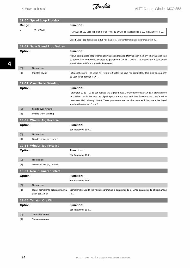
19-50 Speed Loop Pro Max.
Range: Function:0 [0 – 10000]
A value of 100 used in parameter 19-49 or 19-50 will be translated to 0.100 in parameter 7-02.
Speed Loop Prop Gain used at full roll diameter. More information see parameter 19-49.
19-51 Save Speed Prop Values
Option: Function:Allows saving speed proportional gain values and tension PID values in memory. The values should
be saved after completing changes to parameters 19-41 – 19-50. The values are automatically
stored when a different material is selected.
[0] * No function
[1] Initiates saving Initiates the save. The value will return to 0 after the save has completed. This function can only
be used when tension if OFF.
19-61 Over Under Winding
Option: Function:Parameter 19-61 - 19-68 can replace the digital Inputs 1-8 when parameter 19-23 is programmed
to 1. When this is the case the digital inputs are not used and their functions are transferred to
parameter 19-61 through 19-68. These parameters act just the same as if they were the digital
inputs with values of 0 and 1.
[0] * Selects over winding
[1] Selects under winding
19-62 Winder Jog Reverse
Option: Function:See Parameter 19-61.
[0] * No function
[1] Selects winder jog reverse
19-63 Winder Jog Forward
Option: Function:See Parameter 19-61.
[0] * No function
[1] Selects winder jog forward
19-64 New Diameter Select
Option: Function:See Parameter 19-61.
[0] * No function
[1] Preset diameter to programmed val-
ue in par. 19-04
Diameter is preset to the value programmed in parameter 19-04 when parameter 19-68 is changed
to 1.
19-65 Tension On/Off
Option: Function:See Parameter 19-61.
[0] * Turns tension off
[1] Turns tension on
4 How to Install VLT® Center Winder MCO 352
24 MG.33.T1.02 - VLT® is a registered Danfoss trademark
4
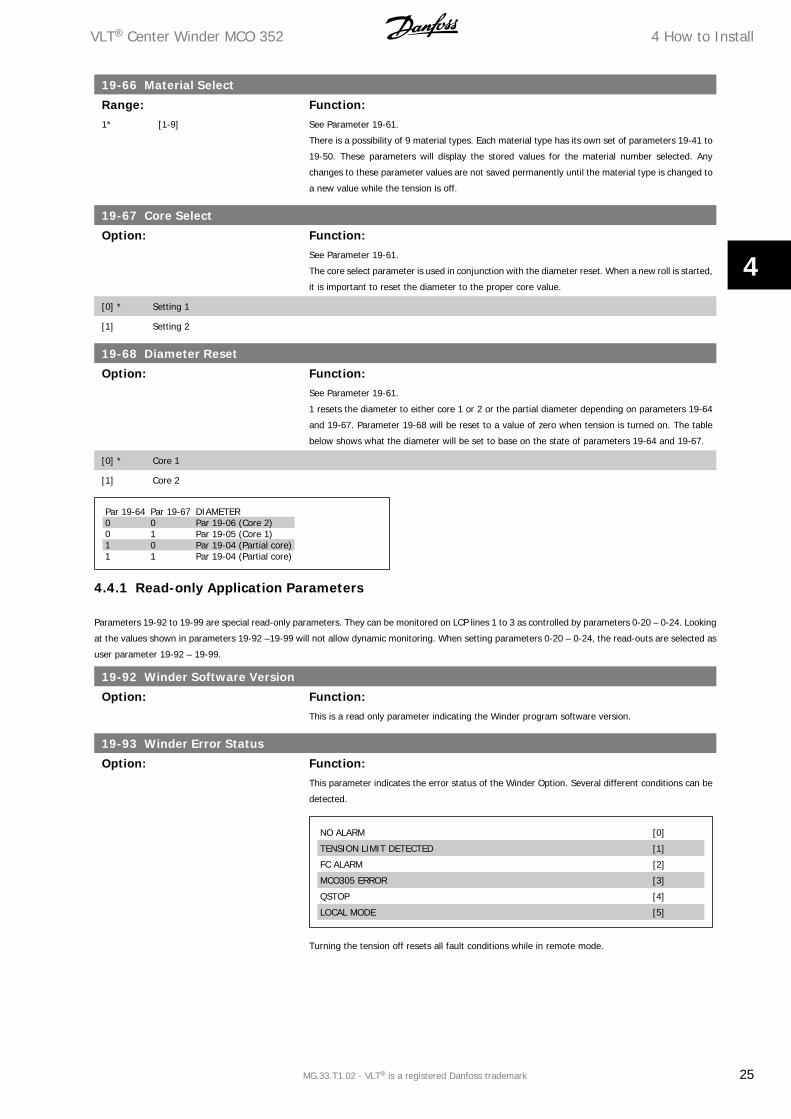
19-66 Material Select
Range: Function:1* [1-9] See Parameter 19-61.
There is a possibility of 9 material types. Each material type has its own set of parameters 19-41 to
19-50. These parameters will display the stored values for the material number selected. Any
changes to these parameter values are not saved permanently until the material type is changed to
a new value while the tension is off.
19-67 Core Select
Option: Function:See Parameter 19-61.
The core select parameter is used in conjunction with the diameter reset. When a new roll is started,
it is important to reset the diameter to the proper core value.
[0] * Setting 1
[1] Setting 2
19-68 Diameter Reset
Option: Function:See Parameter 19-61.
1 resets the diameter to either core 1 or 2 or the partial diameter depending on parameters 19-64
and 19-67. Parameter 19-68 will be reset to a value of zero when tension is turned on. The table
below shows what the diameter will be set to base on the state of parameters 19-64 and 19-67.
[0] * Core 1
[1] Core 2
Par 19-64 Par 19-67 DIAMETER0 0 Par 19-06 (Core 2)0 1 Par 19-05 (Core 1)1 0 Par 19-04 (Partial core)1 1 Par 19-04 (Partial core)
4.4.1 Read-only Application Parameters
Parameters 19-92 to 19-99 are special read-only parameters. They can be monitored on LCP lines 1 to 3 as controlled by parameters 0-20 – 0-24. Looking
at the values shown in parameters 19-92 –19-99 will not allow dynamic monitoring. When setting parameters 0-20 – 0-24, the read-outs are selected as
user parameter 19-92 – 19-99.
19-92 Winder Software Version
Option: Function:This is a read only parameter indicating the Winder program software version.
19-93 Winder Error Status
Option: Function:This parameter indicates the error status of the Winder Option. Several different conditions can be
detected.
NO ALARM [0]
TENSION LIMIT DETECTED [1]
FC ALARM [2]
MCO305 ERROR [3]
QSTOP [4]
LOCAL MODE [5]
Turning the tension off resets all fault conditions while in remote mode.
VLT® Center Winder MCO 352 4 How to Install
MG.33.T1.02 - VLT® is a registered Danfoss trademark 25
4
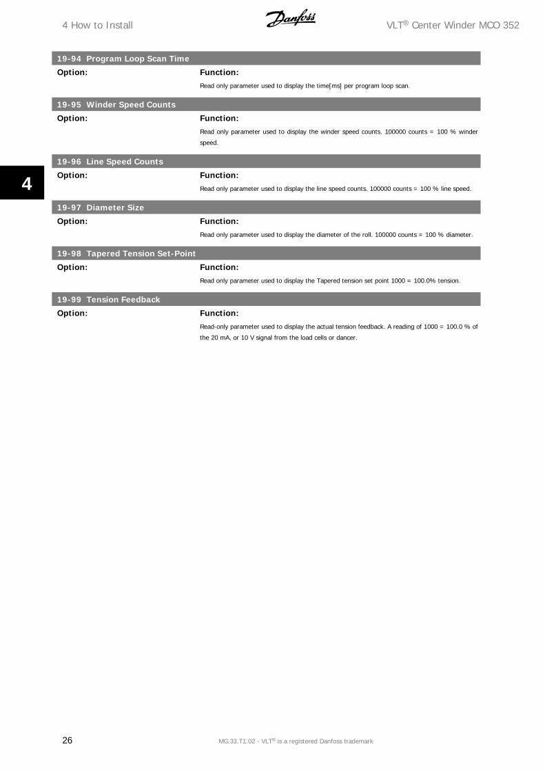
19-94 Program Loop Scan Time
Option: Function:Read only parameter used to display the time[ms] per program loop scan.
19-95 Winder Speed Counts
Option: Function:Read only parameter used to display the winder speed counts. 100000 counts = 100 % winder
speed.
19-96 Line Speed Counts
Option: Function:Read only parameter used to display the line speed counts. 100000 counts = 100 % line speed.
19-97 Diameter Size
Option: Function:Read only parameter used to display the diameter of the roll. 100000 counts = 100 % diameter.
19-98 Tapered Tension Set-Point
Option: Function:Read only parameter used to display the Tapered tension set point 1000 = 100.0% tension.
19-99 Tension Feedback
Option: Function:Read-only parameter used to display the actual tension feedback. A reading of 1000 = 100.0 % of
the 20 mA, or 10 V signal from the load cells or dancer.
4 How to Install VLT® Center Winder MCO 352
26 MG.33.T1.02 - VLT® is a registered Danfoss trademark
4
5 Center Winder Calibration
5.1.1 Frequency Converter Checkout
The VLT AutomationDrive frequency converter should be checked out before installing the Winder software.
1. Ensure proper wiring
2. Power-up the drive.
3. Perform an Automatic Motor Adaptation (AMA) after programming motor nameplate information (parameters 1-20 to 1-26). Inputs 27 and 37
should be turned ON. Use the [Hand On], [Off] and [Reset] keys for local mode control.
4. Determine max speed of winder (RPM) and program into parameter 3-03. Calculate the actual maximum winder speed at the smallest core and
set par. 3-03 for 10 % higher than that value. This value cannot exceed 4,500 RPM.
5. Insure that the winder motor encoder is rated for the maximum RPM used. Enter the winder motor encoder resolution (PPR) into parameter
32-01.
6. It is suggested that the ramp times be increased for initial testing. Set parameters 3-41 and 3-42 to a few seconds. These settings will be changed
later.
7. Determine proper encoder wiring. Set the local reference = 100 RPM. Use the [Hand On] and [Off] keys for local mode control. Check that the
motor runs stable at 100 RPM. If the drive indicates a Warning 12 Torque Limit or Alarm 61 Tracking error while attempting to run at low speed,
the encoder is most likely wired backwards. Swap the A and A’ leads and test again. The direction the motor rotates is the forward direction.
This direction can be reversed by removing power and swapping two motor phases and swapping the A and A’ encoder leads.
8. Tune the speed loop PID: The VLT AutomationDrive will run in a Speed Closed-Loop Mode (par. 1-00). The speed loop PID values (par. 7-00 –
7-08) need to be set to allow stable operation at all speeds and loads. It is expected that the speed proportional gain will need to be increased
at larger roll diameters. The goal of this test is to determine an integral value (par. 7-03) that works well under all conditions and find the
proportional gain values (par. 7-02) that work best at core and at full roll.
a. Running the motor in local mode is the simplest way to test changes in PID settings. Experienced MCO users may choose to use the APOSS
program Testrun function. If using the Testrun function, program for the encoder used return the drive to remote mode and reset the ramp
times (par. 3-41 and 3-42) to 0.05 s. Turn the MCO BANDWIDTH to 0 and use the feed forward velocity factor only for each test-run. This will
show turn off the closed-loop positioning controller and show the response and stability of the FC 300 drive speed PID control.
b. Begin running with an empty core. Adjust the parameters 7-02 and 7-03 for the best performance at low and high speeds. Use the local reference
to adjust the speed if not using Testrun. Note the proportional setting.
c. Now place a full roll on the winder. Adjust the parameters 7-02 and 7-03 for the best performance at low and high speed. Again note the
proportional setting. If any others settings were changed, repeat test with core only and this time only change proportional setting to the value
that was used before at core.
d. Once the values for core and full roll are found, set them into the parameter 19-49 (core) and 19-50 (full roll). A value of 0.100 used in parameter
7-02 has to be set to 100 in parameter 19-49 or 19-50. The proportional gain values for the intermediate diameters are calculated internally in
the Center Winder option program. Parameter 19-49 = min. speed prop gain (core prop) Parameter 19-50 = max. speed prop gain (full roll
prop)
NB!
Note that there may be a need to modify these settings for different materials or roll widths. The Winder Option will allow unique speed
Proportional values as well as the Tension PID values for each of up to nine materials.
NB!
Parameters 19-41 to 19-50 must be saved with parameter 19-51.
NB!
If parameter 19-96 is negative, encoder channels A and B have to be switched.
VLT® Center Winder MCO 352 5 Center Winder Calibration
MG.33.T1.02 - VLT® is a registered Danfoss trademark 27
5
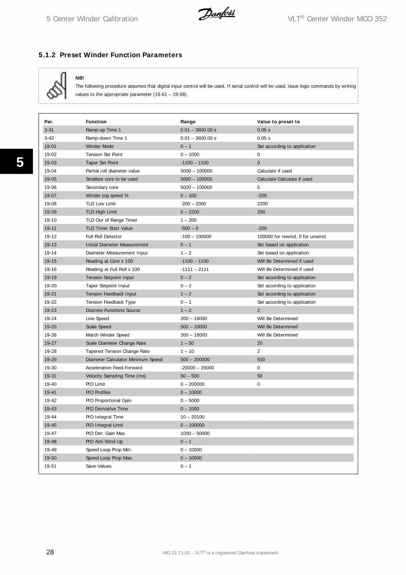
5.1.2 Preset Winder Function Parameters
NB!
The following procedure assumes that digital input control will be used. If serial control will be used, issue logic commands by writing
values to the appropriate parameter (19-61 – 19-68).
Par. Function Range Value to preset to
3-41 Ramp-up Time 1 0.01 – 3600.00 s 0.05 s
3-42 Ramp-down Time 1 0.01 – 3600.00 s 0.05 s
19-01 Winder Mode 0 – 1 Set according to application
19-02 Tension Set Point 0 – 1000 0
19-03 Taper Set Point -1100 – 1100 0
19-04 Partial roll diameter value 5000 – 100000 Calculate if used
19-05 Smallest core to be used 5000 – 100000 Calculate Calculate if used
19-06 Secondary core 5000 – 100000 5
19-07 Winder jog speed % 0 – 100 -200
19-08 TLD Low Limit -200 – 2000 2200
19-09 TLD High Limit 0 – 2200 200
19-10 TLD Out of Range Timer 1 – 200
19-11 TLD Timer Start Value -500 – 0 -200
19-12 Full Roll Detector -100 – 100000 100000 for rewind, 0 for unwind
19-13 Initial Diameter Measurement 0 – 1 Set based on application
19-14 Diameter Measurement Input 1 – 2 Set based on application
19-15 Reading at Core x 100 -1100 – 1100 Will Be Determined if used
19-16 Reading at Full Roll x 100 -1111 – 2111 Will Be Determined if used
19-19 Tension Setpoint Input 0 – 2 Set according to application
19-20 Taper Setpoint Input 0 – 2 Set according to application
19-21 Tension Feedback Input 1 – 2 Set according to application
19-22 Tension Feedback Type 0 – 1 Set according to application
19-23 Discrete Functions Source 1 – 2 2
19-24 Line Speed 200 – 18000 Will Be Determined
19-25 Scale Speed 500 – 10000 Will Be Determined
19-26 Match Winder Speed 200 – 18000 Will Be Determined
19-27 Scale Diameter Change Rate 1 – 50 20
19-28 Tapered Tension Change Rate 1 – 10 2
19-29 Diameter Calculator Minimum Speed 500 – 200000 500
19-30 Acceleration Feed-Forward -20000 – 20000 0
19-31 Velocity Sampling Time (ms) 50 – 500 50
19-40 PID Limit 0 – 200000 0
19-41 PID Profiles 0 – 10000
19-42 PID Proportional Gain 0 – 5000
19-43 PID Derivative Time 0 – 1000
19-44 PID Integral Time 10 – 20100
19-45 PID Integral Limit 0 – 100000
19-47 PID Der. Gain Max 1000 – 50000
19-48 PID Anti Wind-Up 0 – 1
19-49 Speed Loop Prop Min. 0 – 10000
19-50 Speed Loop Prop Max. 0 – 10000
19-51 Save Values 0 – 1
5 Center Winder Calibration VLT® Center Winder MCO 352
28 MG.33.T1.02 - VLT® is a registered Danfoss trademark
5

5.1.3 Winder Scaling Factor Calibration – Open loop Speed Adjustments
The procedure for setting the next three scaling parameters requires that the machine is able to run the line without material. If this is not possible,
empirical calculations can be performed.
1. Set parameter 19-24 “Line Speed Scale”
• Place the smallest empty core on the winder station.
• Issue a Tension-ON command to the Winder. This will require an input at terminals 27, 37, and I5.
• Run the line up to max speed.
• Adjust Line Speed Scale parameter 19-24 so that Displayed Line Speed Counts displayed on the LCP indicates 100,000 counts.
• If the values are negative, turn the line off, power-down the drive and re-wire the line speed encoder A and A’ leads.
• Re-test after changing encoder wiring.
Empirical calculation: The Line Speed Scaling factor can be calculated according to this formula
Par. 19 − 24 = (Max . Line encoder pulse frequency ) × 450
The maximum pulse frequency (Hz) can be found if the encoder resolutions in pulses-per-revolution (PPR) and maximum encoder speed in RPM are
known.
Hz = rpm60 × ppr
2. Set parameters 19-25 “Speed Match” & 19-26 “Winder Speed Scale”
• Verify that the smallest core size (parameter 19-05) has been programmed correctly. The value entered is a percentage of the 100,000 full roll
value. For example, if using a 20 inch full roll with a 3.75 inches core,
Par. 19 − 05 = 3.7520 × 100, 000 = 18, 750
• Open Input 7 “CORE SELECT”
• Open Input 4 “PARTIAL ROLL DIAMETER”
• Momentarily close Input 8 “DIAMETER RESET” Confirm that the displayed Diameter is the value set in parameter 19-05.
• Close Input 5 “TENSION ON”
• Return to maximum line speed to again obtain 100,000 line speed encoder counts. The winder should begin running along with the line speed
encoder.
• Adjust parameter 19-25 “Speed Match” so that core surface speed matches the surface speed of the main line section.
Empirical calculation: Assuming that parameter 3-03 is set to 110 % of the maximum winder speed required at maximum line speed, this will result
in a 90 % reference signal to the Winder drive. The value 16384 (4000Hex) is a scaled value representing 100 % reference.
Par. 19 − 25 = 16384 × 0, 9 × par. 19 − 05100, 000
Remaining at maximum line speed, adjust parameter 19-26 “Winder Speed Scale” so that Winder Speed reads from the LCP reads 100,000 counts.
Empirical calculation: The winder encoder pulse frequency will need to be calculated for operation at maximum line speed on the smallest core.
Par. 19 − 26 = (max. winder encoder pulse frequency ) × 450
• Turn line off so line encoder is zero.
• Open Input 5 “TENSION OFF”.
• Enable the diameter calculator by reducing the setting of parameter 19-29 to 500.
• Close Input 5 “TENSION ON” and re-start the line. If the scaling parameters are set correctly, the diameter should remain very close to the core
diameter value.
• Stop the line and open Input 5 “TENSION OFF”.
VLT® Center Winder MCO 352 5 Center Winder Calibration
MG.33.T1.02 - VLT® is a registered Danfoss trademark 29
5
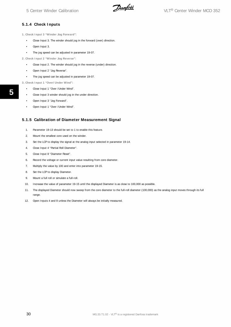
5.1.4 Check Inputs
1. Check Input 3 “Winder Jog Forward”:
• Close Input 3. The winder should jog in the forward (over) direction.
• Open Input 3.
• The jog speed can be adjusted in parameter 19-07.
2. Check Input 2 “Winder Jog Reverse”:
• Close Input 2. The winder should jog in the reverse (under) direction.
• Open Input 2 “Jog Reverse”.
• The jog speed can be adjusted in parameter 19-07.
3. Check Input 1 “Over/Under Wind”:
• Close Input 1 “Over /Under Wind”.
• Close Input 3 winder should jog in the under direction.
• Open Input 3 “Jog Forward”.
• Open Input 1 “Over /Under Wind”.
5.1.5 Calibration of Diameter Measurement Signal
1. Parameter 19-13 should be set to 1 to enable this feature.
2. Mount the smallest core used on the winder.
3. Set the LCP to display the signal at the analog input selected in parameter 19-14.
4. Close Input 4 “Partial Roll Diameter”.
5. Close Input 8 “Diameter Reset”.
6. Record the voltage or current input value resulting from core diameter.
7. Multiply the value by 100 and enter into parameter 19-15.
8. Set the LCP to display Diameter.
9. Mount a full roll or simulate a full-roll.
10. Increase the value of parameter 19-15 until the displayed Diameter is as close to 100,000 as possible.
11. The displayed Diameter should now sweep from the core diameter to the full-roll diameter (100,000) as the analog input moves through its full
range.
12. Open Inputs 4 and 8 unless the Diameter will always be initially measured.
5 Center Winder Calibration VLT® Center Winder MCO 352
30 MG.33.T1.02 - VLT® is a registered Danfoss trademark
5
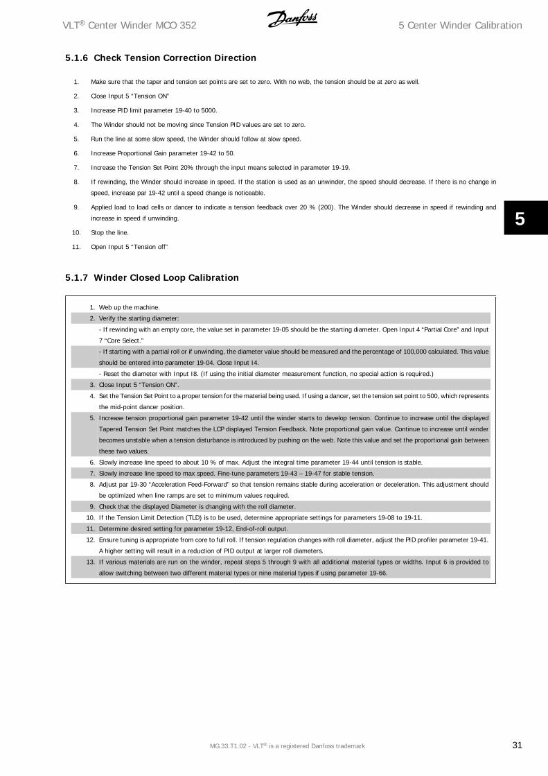
5.1.6 Check Tension Correction Direction
1. Make sure that the taper and tension set points are set to zero. With no web, the tension should be at zero as well.
2. Close Input 5 “Tension ON”
3. Increase PID limit parameter 19-40 to 5000.
4. The Winder should not be moving since Tension PID values are set to zero.
5. Run the line at some slow speed, the Winder should follow at slow speed.
6. Increase Proportional Gain parameter 19-42 to 50.
7. Increase the Tension Set Point 20% through the input means selected in parameter 19-19.
8. If rewinding, the Winder should increase in speed. If the station is used as an unwinder, the speed should decrease. If there is no change in
speed, increase par 19-42 until a speed change is noticeable.
9. Applied load to load cells or dancer to indicate a tension feedback over 20 % (200). The Winder should decrease in speed if rewinding and
increase in speed if unwinding.
10. Stop the line.
11. Open Input 5 “Tension off”
5.1.7 Winder Closed Loop Calibration
1. Web up the machine.
2. Verify the starting diameter:
- If rewinding with an empty core, the value set in parameter 19-05 should be the starting diameter. Open Input 4 “Partial Core” and Input
7 “Core Select.”
- If starting with a partial roll or if unwinding, the diameter value should be measured and the percentage of 100,000 calculated. This value
should be entered into parameter 19-04. Close Input I4.
- Reset the diameter with Input I8. (If using the initial diameter measurement function, no special action is required.)
3. Close Input 5 “Tension ON”.
4. Set the Tension Set Point to a proper tension for the material being used. If using a dancer, set the tension set point to 500, which represents
the mid-point dancer position.
5. Increase tension proportional gain parameter 19-42 until the winder starts to develop tension. Continue to increase until the displayed
Tapered Tension Set Point matches the LCP displayed Tension Feedback. Note proportional gain value. Continue to increase until winder
becomes unstable when a tension disturbance is introduced by pushing on the web. Note this value and set the proportional gain between
these two values.
6. Slowly increase line speed to about 10 % of max. Adjust the integral time parameter 19-44 until tension is stable.
7. Slowly increase line speed to max speed. Fine-tune parameters 19-43 – 19-47 for stable tension.
8. Adjust par 19-30 “Acceleration Feed-Forward” so that tension remains stable during acceleration or deceleration. This adjustment should
be optimized when line ramps are set to minimum values required.
9. Check that the displayed Diameter is changing with the roll diameter.
10. If the Tension Limit Detection (TLD) is to be used, determine appropriate settings for parameters 19-08 to 19-11.
11. Determine desired setting for parameter 19-12, End-of-roll output.
12. Ensure tuning is appropriate from core to full roll. If tension regulation changes with roll diameter, adjust the PID profiler parameter 19-41.
A higher setting will result in a reduction of PID output at larger roll diameters.
13. If various materials are run on the winder, repeat steps 5 through 9 with all additional material types or widths. Input 6 is provided to
allow switching between two different material types or nine material types if using parameter 19-66.
VLT® Center Winder MCO 352 5 Center Winder Calibration
MG.33.T1.02 - VLT® is a registered Danfoss trademark 31
5
6 Troubleshooting VLT® Center Winder MCO 352
32 MG.33.T1.02 - VLT® is a registered Danfoss trademark
6
6 Troubleshooting
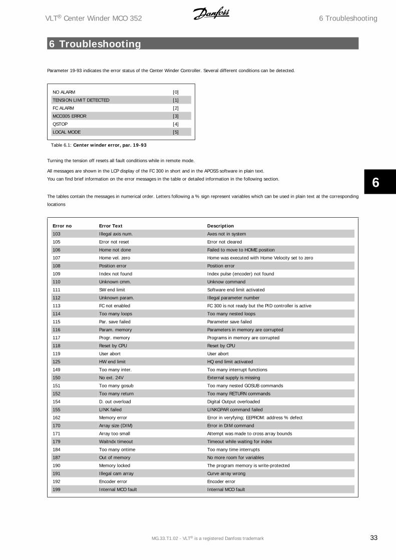
Parameter 19-93 indicates the error status of the Center Winder Controller. Several different conditions can be detected.
NO ALARM [0]
TENSION LIMIT DETECTED [1]
FC ALARM [2]
MCO305 ERROR [3]
QSTOP [4]
LOCAL MODE [5]
Table 6.1: Center winder error, par. 19-93
Turning the tension off resets all fault conditions while in remote mode.
All messages are shown in the LCP display of the FC 300 in short and in the APOSS software in plain text.
You can find brief information on the error messages in the table or detailed information in the following section.
The tables contain the messages in numerical order. Letters following a % sign represent variables which can be used in plain text at the corresponding
locations
Error no Error Text Description
103 Illegal axis num. Axes not in system
105 Error not reset Error not cleared
106 Home not done Failed to move to HOME position
107 Home vel. zero Home was executed with Home Velocity set to zero
108 Position error Position error
109 Index not found Index pulse (encoder) not found
110 Unknown cmm. Unknow command
111 SW end limit Software end limit activated
112 Unknown param. Illegal parameter number
113 FC not enabled FC 300 is not ready but the PID controller is active
114 Too many loops Too many nested loops
115 Par. save failed Parameter save failed
116 Param. memory Parameters in memory are corrupted
117 Progr. memory Programs in memory are corrupted
118 Reset by CPU Reset by CPU
119 User abort User abort
125 HW end limit HQ end limit activated
149 Too many inter. Too many interrupt functions
150 No ext. 24V External supply is missing
151 Too many gosub Too many nested GOSUB commands
152 Too many return Too many RETURN commands
154 D. out overload Digital Output overloaded
155 LINK failed LINKGPAR command failed
162 Memory error Error in veryfying; EEPROM: address % defect
170 Array size (DIM) Error in DIM command
171 Array too small Attempt was made to cross array bounds
179 Waitndx timeout Timeout while waiting for index
184 Too many ontime Too many time interrupts
187 Out of memory No more room for variables
190 Memory locked The program memory is write-protected
191 Illegal cam array Curve array wrong
192 Encoder error Encoder error
199 Internal MCO fault Internal MCO fault
VLT® Center Winder MCO 352 6 Troubleshooting
MG.33.T1.02 - VLT® is a registered Danfoss trademark 33
6

7 Appendix VLT® Center Winder MCO 352
34 MG.33.T1.02 - VLT® is a registered Danfoss trademark
7
7 Appendix
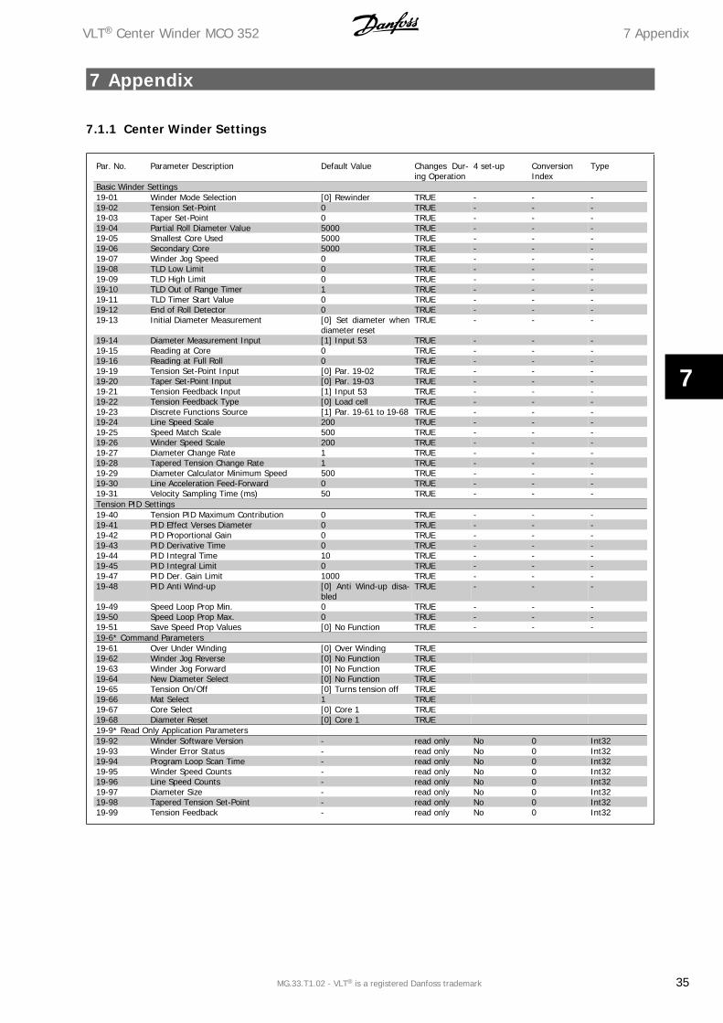
7.1.1 Center Winder Settings
Par. No. Parameter Description Default Value Changes Dur-ing Operation
4 set-up ConversionIndex
Type
Basic Winder Settings19-01 Winder Mode Selection [0] Rewinder TRUE - - -19-02 Tension Set-Point 0 TRUE - - -19-03 Taper Set-Point 0 TRUE - - -19-04 Partial Roll Diameter Value 5000 TRUE - - -19-05 Smallest Core Used 5000 TRUE - - -19-06 Secondary Core 5000 TRUE - - -19-07 Winder Jog Speed 0 TRUE - - -19-08 TLD Low Limit 0 TRUE - - -19-09 TLD High Limit 0 TRUE - - -19-10 TLD Out of Range Timer 1 TRUE - - -19-11 TLD Timer Start Value 0 TRUE - - -19-12 End of Roll Detector 0 TRUE - - -19-13 Initial Diameter Measurement [0] Set diameter when
diameter resetTRUE - - -
19-14 Diameter Measurement Input [1] Input 53 TRUE - - -19-15 Reading at Core 0 TRUE - - -19-16 Reading at Full Roll 0 TRUE - - -19-19 Tension Set-Point Input [0] Par. 19-02 TRUE - - -19-20 Taper Set-Point Input [0] Par. 19-03 TRUE - - -19-21 Tension Feedback Input [1] Input 53 TRUE - - -19-22 Tension Feedback Type [0] Load cell TRUE - - -19-23 Discrete Functions Source [1] Par. 19-61 to 19-68 TRUE - - -19-24 Line Speed Scale 200 TRUE - - -19-25 Speed Match Scale 500 TRUE - - -19-26 Winder Speed Scale 200 TRUE - - -19-27 Diameter Change Rate 1 TRUE - - -19-28 Tapered Tension Change Rate 1 TRUE - - -19-29 Diameter Calculator Minimum Speed 500 TRUE - - -19-30 Line Acceleration Feed-Forward 0 TRUE - - -19-31 Velocity Sampling Time (ms) 50 TRUE - - -Tension PID Settings19-40 Tension PID Maximum Contribution 0 TRUE - - -19-41 PID Effect Verses Diameter 0 TRUE - - -19-42 PID Proportional Gain 0 TRUE - - -19-43 PID Derivative Time 0 TRUE - - -19-44 PID Integral Time 10 TRUE - - -19-45 PID Integral Limit 0 TRUE - - -19-47 PID Der. Gain Limit 1000 TRUE - - -19-48 PID Anti Wind-up [0] Anti Wind-up disa-
bledTRUE - - -
19-49 Speed Loop Prop Min. 0 TRUE - - -19-50 Speed Loop Prop Max. 0 TRUE - - -19-51 Save Speed Prop Values [0] No Function TRUE - - -19-6* Command Parameters19-61 Over Under Winding [0] Over Winding TRUE19-62 Winder Jog Reverse [0] No Function TRUE19-63 Winder Jog Forward [0] No Function TRUE19-64 New Diameter Select [0] No Function TRUE19-65 Tension On/Off [0] Turns tension off TRUE19-66 Mat Select 1 TRUE19-67 Core Select [0] Core 1 TRUE19-68 Diameter Reset [0] Core 1 TRUE19-9* Read Only Application Parameters19-92 Winder Software Version - read only No 0 Int3219-93 Winder Error Status - read only No 0 Int3219-94 Program Loop Scan Time - read only No 0 Int3219-95 Winder Speed Counts - read only No 0 Int3219-96 Line Speed Counts - read only No 0 Int3219-97 Diameter Size - read only No 0 Int3219-98 Tapered Tension Set-Point - read only No 0 Int3219-99 Tension Feedback - read only No 0 Int32
VLT® Center Winder MCO 352 7 Appendix
MG.33.T1.02 - VLT® is a registered Danfoss trademark 35
7
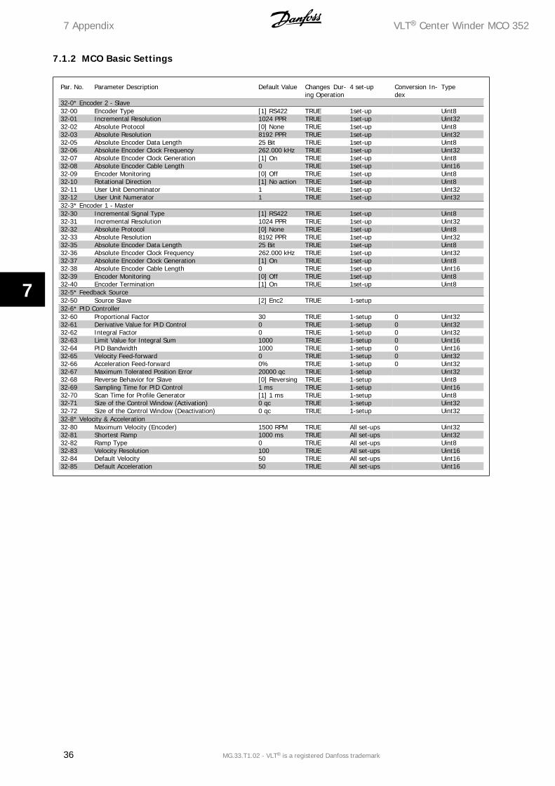
7.1.2 MCO Basic Settings
Par. No. Parameter Description Default Value Changes Dur-ing Operation
4 set-up Conversion In-dex
Type
32-0* Encoder 2 - Slave32-00 Encoder Type [1] RS422 TRUE 1set-up Uint832-01 Incremental Resolution 1024 PPR TRUE 1set-up Uint3232-02 Absolute Protocol [0] None TRUE 1set-up Uint832-03 Absolute Resolution 8192 PPR TRUE 1set-up Uint3232-05 Absolute Encoder Data Length 25 Bit TRUE 1set-up Uint832-06 Absolute Encoder Clock Frequency 262.000 kHz TRUE 1set-up Uint3232-07 Absolute Encoder Clock Generation [1] On TRUE 1set-up Uint832-08 Absolute Encoder Cable Length 0 TRUE 1set-up Uint1632-09 Encoder Monitoring [0] Off TRUE 1set-up Uint832-10 Rotational Direction [1] No action TRUE 1set-up Uint832-11 User Unit Denominator 1 TRUE 1set-up Uint3232-12 User Unit Numerator 1 TRUE 1set-up Uint3232-3* Encoder 1 - Master32-30 Incremental Signal Type [1] RS422 TRUE 1set-up Uint832-31 Incremental Resolution 1024 PPR TRUE 1set-up Uint3232-32 Absolute Protocol [0] None TRUE 1set-up Uint832-33 Absolute Resolution 8192 PPR TRUE 1set-up Uint3232-35 Absolute Encoder Data Length 25 Bit TRUE 1set-up Uint832-36 Absolute Encoder Clock Frequency 262.000 kHz TRUE 1set-up Uint3232-37 Absolute Encoder Clock Generation [1] On TRUE 1set-up Uint832-38 Absolute Encoder Cable Length 0 TRUE 1set-up Uint1632-39 Encoder Monitoring [0] Off TRUE 1set-up Uint832-40 Encoder Termination [1] On TRUE 1set-up Uint832-5* Feedback Source32-50 Source Slave [2] Enc2 TRUE 1-setup32-6* PID Controller32-60 Proportional Factor 30 TRUE 1-setup 0 Uint3232-61 Derivative Value for PID Control 0 TRUE 1-setup 0 Uint3232-62 Integral Factor 0 TRUE 1-setup 0 Uint3232-63 Limit Value for Integral Sum 1000 TRUE 1-setup 0 Uint1632-64 PID Bandwidth 1000 TRUE 1-setup 0 Uint1632-65 Velocity Feed-forward 0 TRUE 1-setup 0 Uint3232-66 Acceleration Feed-forward 0% TRUE 1-setup 0 Uint3232-67 Maximum Tolerated Position Error 20000 qc TRUE 1-setup Uint3232-68 Reverse Behavior for Slave [0] Reversing TRUE 1-setup Uint832-69 Sampling Time for PID Control 1 ms TRUE 1-setup Uint1632-70 Scan Time for Profile Generator [1] 1 ms TRUE 1-setup Uint832-71 Size of the Control Window (Activation) 0 qc TRUE 1-setup Uint3232-72 Size of the Control Window (Deactivation) 0 qc TRUE 1-setup Uint3232-8* Velocity & Acceleration32-80 Maximum Velocity (Encoder) 1500 RPM TRUE All set-ups Uint3232-81 Shortest Ramp 1000 ms TRUE All set-ups Uint3232-82 Ramp Type 0 TRUE All set-ups Uint832-83 Velocity Resolution 100 TRUE All set-ups Uint1632-84 Default Velocity 50 TRUE All set-ups Uint1632-85 Default Acceleration 50 TRUE All set-ups Uint16
7 Appendix VLT® Center Winder MCO 352
36 MG.33.T1.02 - VLT® is a registered Danfoss trademark
7
IndexAAbbreviations 4
Acceleration Feed-forward 8, 22, 28, 31, 35
Additional Features 8
Analog Inputs 16, 20
Analog Inputs 8, 16
Analog Output 16
Application Parameters 25
Approvals 3
Approvals 3
BBasic Winder Settings 35
Block Diagram 7, 8
CCalibratio 9
Calibration 3, 29, 30, 31
Check Inputs 30
Check Tension Correction Direction 31
Commencing Repair Work 5
DDancer Feedback 7, 9
Diameter Calculator 29
Diameter Calculator 8, 22, 28, 35
Diameter Measurement Signal 8
Diameter Measurement Signal 30
Digital Inputs 9, 21
Digital Inputs 24
Digital Inputs 9
Digital Output 19
Digital Outputs 9
EEnd Of Roll Detection 8
FFrequency Converter Checkout 27
GGeneral Warning 6
General Warnings 3
HHigh Voltage Warning 5
How To Read 3
IInitial Diameter Measurement 8, 31
Initial Diameter Measurement 16
Initial Diameter Measurement 20, 28, 35
LLimiter 8
Literature 3
Literature 3
VLT® Center Winder MCO 352 Index
MG.33.T1.02 - VLT® is a registered Danfoss trademark 37
MMco Basic Settings 36
Minimum Speed 8, 22, 28, 35
OOpen Loop Speed Adjustments 29
PPreset Winder Function Parameters 28
RRelay Output 15
SSafe Stop Of Vlt Automationdrive Fc302 6
Safety Instructions 3, 5
Symbols 3
Symbols 3
System Requirements 9
TTension And Taper Set-points 8
Tension And Taper Set-points 9
Tension Limit Detector 8, 15, 18, 19
Tension-taper Set-point Ramp 8
Terminals 3, 5, 29
UUnintended Start 5
VVlt Automationdrive Terminals 11
WWinder Closed Loop 31
Winder Scaling Factor 29
Index VLT® Center Winder MCO 352
38 MG.33.T1.02 - VLT® is a registered Danfoss trademark

Rev. 2008-02-04
www.danfoss.com/drives
130R0332 MG33T102
*MG33T102*