VLT Contents Quick Setup Introduction to VLT 2800 Programming · VLT® 2800 Series Quick Setup...
95
VLT ® 2800 Series ■ Contents Quick Setup ....................................................................................................... 3 General warning ..................................................................................................... 3 Mechanical Installation ........................................................................................... 3 Electrical Installation, power ................................................................................... 3 Electrical Installation, control cables ....................................................................... 3 Programming ......................................................................................................... 3 Motor start ............................................................................................................. 4 Safety regulations .................................................................................................. 4 Warning against unintended start ........................................................................... 4 Introduction to VLT 2800 ............................................................................. 5 Software version .................................................................................................... 5 High voltage warning ............................................................................................. 7 These rules concern your safety ............................................................................. 7 Warning against unintended start ........................................................................... 7 Control unit ............................................................................................................ 8 Manual initialisation ................................................................................................. 8 Hand Auto ............................................................................................................. 9 Automatic motor tuning ......................................................................................... 10 Programming .................................................................................................... 11 Operation & Display ............................................................................................... 11 Load and Motor ..................................................................................................... 18 References & Limits ............................................................................................... 28 Inputs and outputs ................................................................................................. 35 Special functions .................................................................................................... 45 Installation ......................................................................................................... 53 Mechanical dimensions .......................................................................................... 53 Mechanical installation ........................................................................................... 57 General information about electrical installation ...................................................... 58 EMC-correct electrical installation .......................................................................... 59 Electrical installation ............................................................................................... 60 Safety clamp .......................................................................................................... 62 Pre-fuses ................................................................................................................ 62 Mains connection ................................................................................................... 62 Motor connection ................................................................................................... 62 RFI switch .............................................................................................................. 63 Direction of motor rotation ..................................................................................... 63 Parallel connection of motors ................................................................................. 63 Motor cables .......................................................................................................... 64 Motor thermal protection ....................................................................................... 64 Brake connection ................................................................................................... 64 Earth connection .................................................................................................... 64 Load sharing .......................................................................................................... 65 Tightening Torque, Power Terminals ...................................................................... 65 Control of mechanical brake .................................................................................. 65 Access to control terminals .................................................................................... 65 Electrical installation, control cables ....................................................................... 66 Tightening torques, control cables .......................................................................... 67 MG.28.A9.02 - VLT is a registered Danfoss trademark 1
Transcript of VLT Contents Quick Setup Introduction to VLT 2800 Programming · VLT® 2800 Series Quick Setup...
VLT® 2800 Series
■ Contents
Quick Setup ....................................................................................................... 3General warning ..................................................................................................... 3Mechanical Installation ........................................................................................... 3Electrical Installation, power ................................................................................... 3Electrical Installation, control cables ....................................................................... 3Programming ......................................................................................................... 3Motor start ............................................................................................................. 4Safety regulations .................................................................................................. 4Warning against unintended start ........................................................................... 4
Introduction to VLT 2800 ............................................................................. 5Software version .................................................................................................... 5High voltage warning ............................................................................................. 7These rules concern your safety ............................................................................. 7Warning against unintended start ........................................................................... 7Control unit ............................................................................................................ 8Manual initialisation ................................................................................................. 8Hand Auto ............................................................................................................. 9Automatic motor tuning ......................................................................................... 10
Programming .................................................................................................... 11Operation & Display ............................................................................................... 11Load and Motor ..................................................................................................... 18References & Limits ............................................................................................... 28Inputs and outputs ................................................................................................. 35Special functions .................................................................................................... 45
Installation ......................................................................................................... 53Mechanical dimensions .......................................................................................... 53Mechanical installation ........................................................................................... 57General information about electrical installation ...................................................... 58EMC-correct electrical installation .......................................................................... 59Electrical installation ............................................................................................... 60Safety clamp .......................................................................................................... 62Pre-fuses ................................................................................................................ 62Mains connection ................................................................................................... 62Motor connection ................................................................................................... 62RFI switch .............................................................................................................. 63Direction of motor rotation ..................................................................................... 63Parallel connection of motors ................................................................................. 63Motor cables .......................................................................................................... 64Motor thermal protection ....................................................................................... 64Brake connection ................................................................................................... 64Earth connection .................................................................................................... 64Load sharing .......................................................................................................... 65Tightening Torque, Power Terminals ...................................................................... 65Control of mechanical brake .................................................................................. 65Access to control terminals .................................................................................... 65Electrical installation, control cables ....................................................................... 66Tightening torques, control cables .......................................................................... 67
MG.28.A9.02 - VLT is a registered Danfoss trademark 1
VLT® 2800 Series
Electrical installation, control terminals ................................................................... 67Relay connection ................................................................................................... 67VLT Software Dialog .............................................................................................. 67Connection examples ............................................................................................ 68
All about VLT 2800 ......................................................................................... 69Order form ............................................................................................................. 69Display readout ...................................................................................................... 70Warnings/alarm messages ..................................................................................... 70Warning words, extended status words and Alarmwords ..................................... 74Special conditions .................................................................................................. 75Aggressive environments ........................................................................................ 75Derating for high switching frequency - VLT 2800 .................................................. 75Temperature-dependent switch frequency ............................................................. 75Galvanic Isolation (PELV) ........................................................................................ 76EMC emission ........................................................................................................ 76UL Standard .......................................................................................................... 78General technical data ........................................................................................... 79Technical data, mains supply 1 x 220 - 240 V/3 x 200-240V ................................ 83Technical data, mains supply 3 x 380 - 480 V ....................................................... 84Available literature ................................................................................................... 85Supplied with the unit ............................................................................................. 85
Index ...................................................................................................................... 93
MG.28.A9.02 - VLT is a registered Danfoss trademark2
VLT® 2800 Series
Qui
ckS
etup
■ Quick Setup
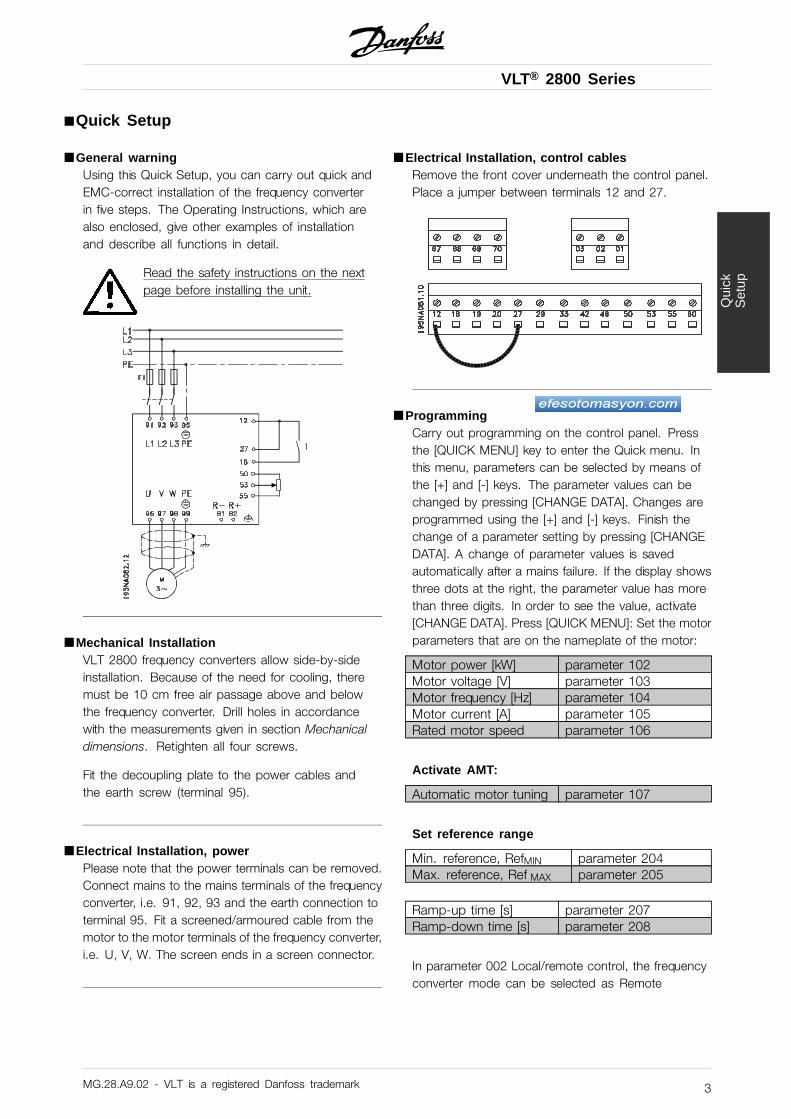
■ General warningUsing this Quick Setup, you can carry out quick andEMC-correct installation of the frequency converterin five steps. The Operating Instructions, which arealso enclosed, give other examples of installationand describe all functions in detail.
Read the safety instructions on the nextpage before installing the unit.
■ Mechanical InstallationVLT 2800 frequency converters allow side-by-sideinstallation. Because of the need for cooling, theremust be 10 cm free air passage above and belowthe frequency converter. Drill holes in accordancewith the measurements given in section Mechanicaldimensions. Retighten all four screws.
Fit the decoupling plate to the power cables andthe earth screw (terminal 95).
■ Electrical Installation, powerPlease note that the power terminals can be removed.Connect mains to the mains terminals of the frequencyconverter, i.e. 91, 92, 93 and the earth connection toterminal 95. Fit a screened/armoured cable from themotor to the motor terminals of the frequency converter,i.e. U, V, W. The screen ends in a screen connector.
■ Electrical Installation, control cablesRemove the front cover underneath the control panel.Place a jumper between terminals 12 and 27.
■ ProgrammingCarry out programming on the control panel. Pressthe [QUICK MENU] key to enter the Quick menu. Inthis menu, parameters can be selected by means ofthe [+] and [-] keys. The parameter values can bechanged by pressing [CHANGE DATA]. Changes areprogrammed using the [+] and [-] keys. Finish thechange of a parameter setting by pressing [CHANGEDATA]. A change of parameter values is savedautomatically after a mains failure. If the display showsthree dots at the right, the parameter value has morethan three digits. In order to see the value, activate[CHANGE DATA]. Press [QUICK MENU]: Set the motorparameters that are on the nameplate of the motor:
Motor power [kW] parameter 102Motor voltage [V] parameter 103Motor frequency [Hz] parameter 104Motor current [A] parameter 105Rated motor speed parameter 106
Activate AMT:
Automatic motor tuning parameter 107
Set reference range
Min. reference, RefMIN parameter 204Max. reference, Ref MAX parameter 205
Ramp-up time [s] parameter 207Ramp-down time [s] parameter 208
In parameter 002 Local/remote control, the frequencyconverter mode can be selected as Remote
MG.28.A9.02 - VLT is a registered Danfoss trademark 3
VLT® 2800 Series
operation [0], i.e. via the control terminals, orLocal [1], i.e. via the control unit.
Set the control location to Local [1].
Local/remote operation = Local [1] Par. 002
Set the motor speed by adjusting theLocal reference
Local reference Parameter 003
■ Motor startPress [Start] to start the motor. Set the motor speedby adjusting parameter 003 Local reference.
Check whether the direction of rotation of the motorshaft is clockwise. If not, exchange any two phaseson the motor cable. Press [STOP/RESET] to stop themotor. Press [QUICK MENU] to return to display mode.[QUICK MENU] + [+] keys must be pressedsimultaneously to give access to all parameters.
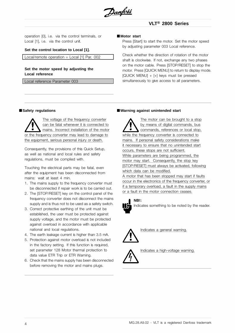
■ Safety regulations
The voltage of the frequency convertercan be fatal whenever it is connected tomains. Incorrect installation of the motor
or the frequency converter may lead to damage tothe equipment, serious personal injury or death.
Consequently, the provisions of this Quick Setup,as well as national and local rules and safetyregulations, must be complied with.
Touching the electrical parts may be fatal, evenafter the equipment has been disconnected frommains: wait at least 4 min.1. The mains supply to the frequency converter must
be disconnected if repair work is to be carried out.2. The [STOP/RESET] key on the control panel of the
frequency converter does not disconnect the mainssupply and is thus not to be used as a safety switch.
3. Correct protective earthing of the unit must beestablished, the user must be protected againstsupply voltage, and the motor must be protectedagainst overload in accordance with applicablenational and local regulations.
4. The earth leakage current is higher than 3.5 mA.5. Protection against motor overload is not included
in the factory setting. If this function is required,set parameter 128 Motor thermal protection todata value ETR Trip or ETR Warning.
6. Check that the mains supply has been disconnectedbefore removing the motor and mains plugs.
■ Warning against unintended start
The motor can be brought to a stopby means of digital commands, buscommands, references or local stop,
while the frequency converter is connected tomains. If personal safety considerations makeit necessary to ensure that no unintended startoccurs, these stops are not sufficient.While parameters are being programmed, themotor may start. Consequently, the stop key[STOP/RESET] must always be activated, followingwhich data can be modified.A motor that has been stopped may start if faultsoccur in the electronics of the frequency converter, orif a temporary overload, a fault in the supply mainsor a fault in the motor connection ceases.
NB!:Indicates something to be noted by the reader.
Indicates a general warning.
Indicates a high-voltage warning.
MG.28.A9.02 - VLT is a registered Danfoss trademark4
VLT® 2800 Series
Intr
oduc
tion
to V
LT28
00
195NA009.17
VLT 2800 Series
Operating instructionsSoftware version: 2.8x
These operating instructions can be used for all VLT 2800Series frequency converters with software version 2.8x.The software version number can be seen from parameter640 Software version no.
MG.28.A9.02 - VLT is a registered Danfoss trademark 5
VLT® 2800 Series
195NA139.10
Warning:It can be extremely dangerous to touch the electrical parts even when the mains
supply has been disconnected.
Also ensure that other voltage inputs are disconnected from load sharing through the
DC bus.
Wait at least 4 minutes after the input power has been removed before servicing the
drive.
MG.28.A9.02 - VLT is a registered Danfoss trademark6
VLT® 2800 Series
Intr
oduc
tion
to V
LT28
00
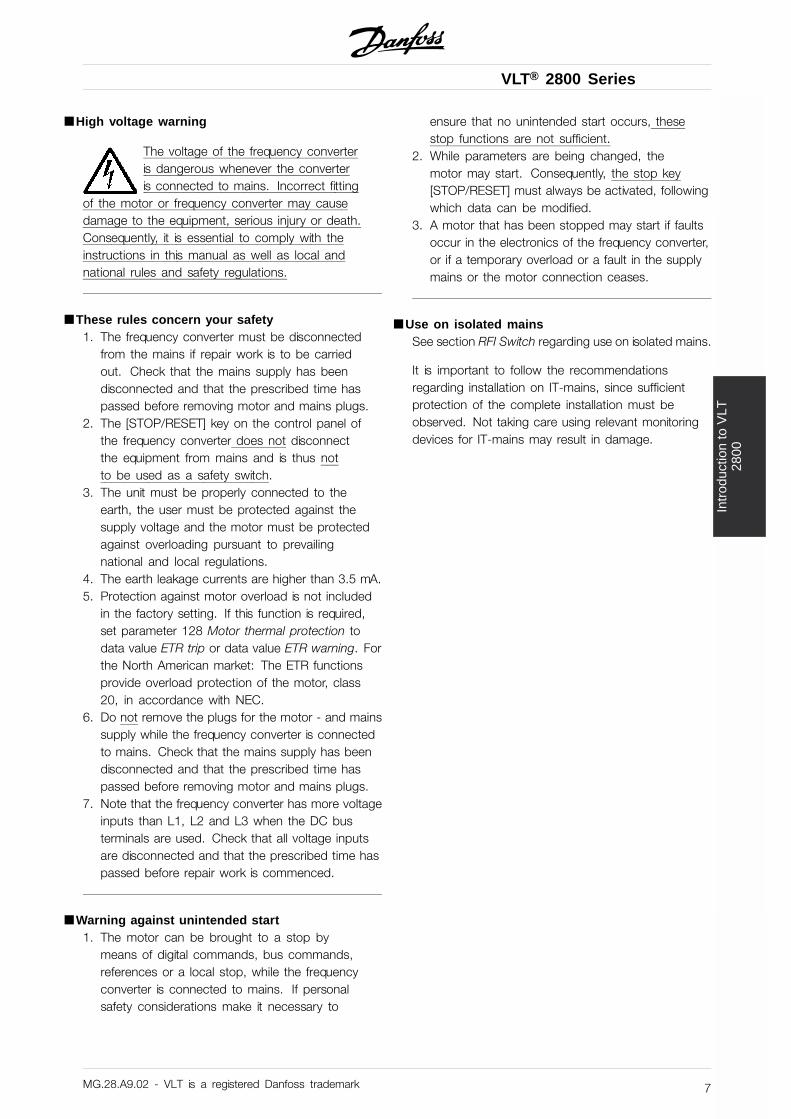
■ High voltage warning
The voltage of the frequency converteris dangerous whenever the converteris connected to mains. Incorrect fitting
of the motor or frequency converter may causedamage to the equipment, serious injury or death.Consequently, it is essential to comply with theinstructions in this manual as well as local andnational rules and safety regulations.
■ These rules concern your safety1. The frequency converter must be disconnected
from the mains if repair work is to be carriedout. Check that the mains supply has beendisconnected and that the prescribed time haspassed before removing motor and mains plugs.
2. The [STOP/RESET] key on the control panel ofthe frequency converter does not disconnectthe equipment from mains and is thus notto be used as a safety switch.
3. The unit must be properly connected to theearth, the user must be protected against thesupply voltage and the motor must be protectedagainst overloading pursuant to prevailingnational and local regulations.
4. The earth leakage currents are higher than 3.5 mA.5. Protection against motor overload is not included
in the factory setting. If this function is required,set parameter 128 Motor thermal protection todata value ETR trip or data value ETR warning. Forthe North American market: The ETR functionsprovide overload protection of the motor, class20, in accordance with NEC.
6. Do not remove the plugs for the motor - and mainssupply while the frequency converter is connectedto mains. Check that the mains supply has beendisconnected and that the prescribed time haspassed before removing motor and mains plugs.
7. Note that the frequency converter has more voltageinputs than L1, L2 and L3 when the DC busterminals are used. Check that all voltage inputsare disconnected and that the prescribed time haspassed before repair work is commenced.
■ Warning against unintended start1. The motor can be brought to a stop by
means of digital commands, bus commands,references or a local stop, while the frequencyconverter is connected to mains. If personalsafety considerations make it necessary to
ensure that no unintended start occurs, thesestop functions are not sufficient.
2. While parameters are being changed, themotor may start. Consequently, the stop key[STOP/RESET] must always be activated, followingwhich data can be modified.
3. A motor that has been stopped may start if faultsoccur in the electronics of the frequency converter,or if a temporary overload or a fault in the supplymains or the motor connection ceases.
■ Use on isolated mainsSee section RFI Switch regarding use on isolated mains.
It is important to follow the recommendationsregarding installation on IT-mains, since sufficientprotection of the complete installation must beobserved. Not taking care using relevant monitoringdevices for IT-mains may result in damage.
MG.28.A9.02 - VLT is a registered Danfoss trademark 7
VLT® 2800 Series
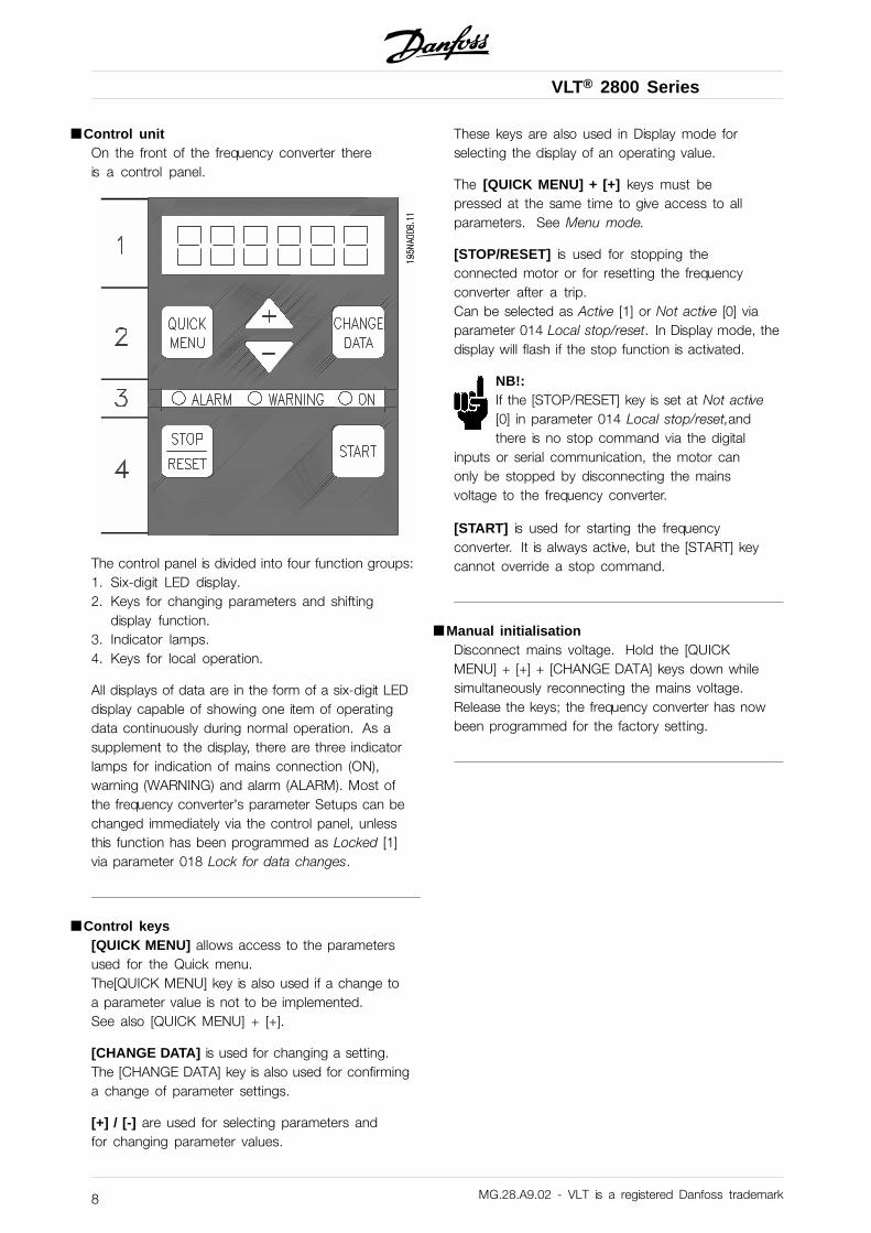
■ Control unitOn the front of the frequency converter thereis a control panel.
The control panel is divided into four function groups:1. Six-digit LED display.2. Keys for changing parameters and shifting
display function.3. Indicator lamps.4. Keys for local operation.
All displays of data are in the form of a six-digit LEDdisplay capable of showing one item of operatingdata continuously during normal operation. As asupplement to the display, there are three indicatorlamps for indication of mains connection (ON),warning (WARNING) and alarm (ALARM). Most ofthe frequency converter’s parameter Setups can bechanged immediately via the control panel, unlessthis function has been programmed as Locked [1]via parameter 018 Lock for data changes.
■ Control keys[QUICK MENU] allows access to the parametersused for the Quick menu.The[QUICK MENU] key is also used if a change toa parameter value is not to be implemented.See also [QUICK MENU] + [+].
[CHANGE DATA] is used for changing a setting.The [CHANGE DATA] key is also used for confirminga change of parameter settings.
[+] / [-] are used for selecting parameters andfor changing parameter values.
These keys are also used in Display mode forselecting the display of an operating value.
The [QUICK MENU] + [+] keys must bepressed at the same time to give access to allparameters. See Menu mode.
[STOP/RESET] is used for stopping theconnected motor or for resetting the frequencyconverter after a trip.Can be selected as Active [1] or Not active [0] viaparameter 014 Local stop/reset. In Display mode, thedisplay will flash if the stop function is activated.
NB!:If the [STOP/RESET] key is set at Not active[0] in parameter 014 Local stop/reset,andthere is no stop command via the digital
inputs or serial communication, the motor canonly be stopped by disconnecting the mainsvoltage to the frequency converter.
[START] is used for starting the frequencyconverter. It is always active, but the [START] keycannot override a stop command.
■ Manual initialisationDisconnect mains voltage. Hold the [QUICKMENU] + [+] + [CHANGE DATA] keys down whilesimultaneously reconnecting the mains voltage.Release the keys; the frequency converter has nowbeen programmed for the factory setting.
MG.28.A9.02 - VLT is a registered Danfoss trademark8
VLT® 2800 Series
Intr
oduc
tion
to V
LT28
00
■ Display readout statesDisplay mode
In normal operation, one item of operating data canbe displayed continuously at the operator’s ownchoice. By means of the [+/-] keys the followingoptions can be selected in Display mode:- Output frequency [Hz]- Output current [A]- Output voltage [V]- Intermediate circuit voltage [V]- Output power [kW]- Scaled output frequency fout x p008
Menu mode
In order to enter the Menu mode [QUICK MENU]+ [+] must be activated at the same time.In Menu mode, most of the frequency converterparameters can be changed. Scroll through theparameters using the [+/-] keys. While scrolling in theMenu mode proceeds, the parameter number will flash.
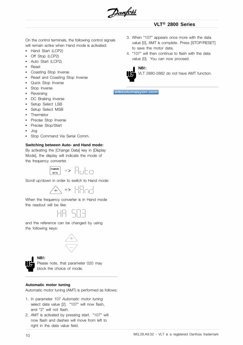
The display shows that the setting in parameter102 Motor power PM,N is 0.75. In order to changethe value of 0.75, [CHANGE DATA] must firstbe activated; the parameter value can then bechanged using the [+/-] keys.
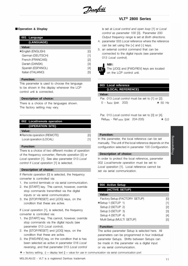
If for a given parameter the display shows threedots at the right, it means that the parametervalue has more than three digits. In order to seethe value, activate [CHANGE DATA].
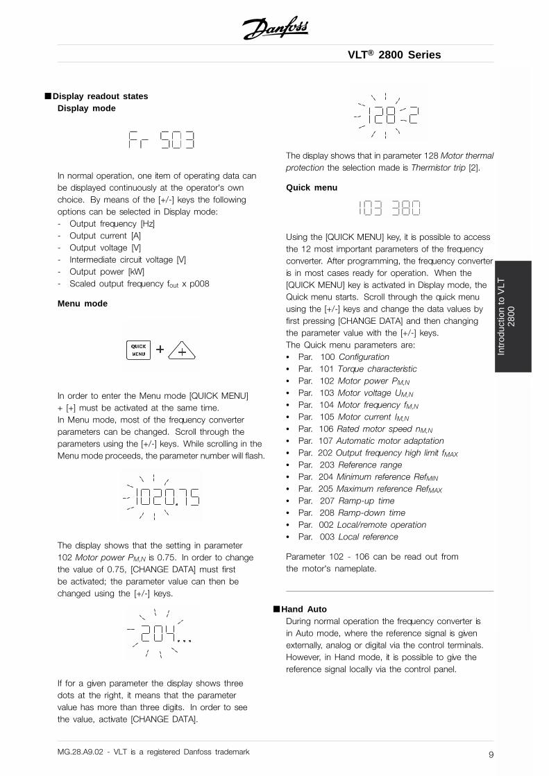
The display shows that in parameter 128 Motor thermalprotection the selection made is Thermistor trip [2].
Quick menu
Using the [QUICK MENU] key, it is possible to accessthe 12 most important parameters of the frequencyconverter. After programming, the frequency converteris in most cases ready for operation. When the[QUICK MENU] key is activated in Display mode, theQuick menu starts. Scroll through the quick menuusing the [+/-] keys and change the data values byfirst pressing [CHANGE DATA] and then changingthe parameter value with the [+/-] keys.The Quick menu parameters are:• Par. 100 Configuration• Par. 101 Torque characteristic• Par. 102 Motor power PM,N
• Par. 103 Motor voltage UM,N
• Par. 104 Motor frequency fM,N
• Par. 105 Motor current IM,N
• Par. 106 Rated motor speed nM,N
• Par. 107 Automatic motor adaptation• Par. 202 Output frequency high limit fMAX
• Par. 203 Reference range• Par. 204 Minimum reference RefMIN
• Par. 205 Maximum reference RefMAX
• Par. 207 Ramp-up time• Par. 208 Ramp-down time• Par. 002 Local/remote operation• Par. 003 Local reference
Parameter 102 - 106 can be read out fromthe motor’s nameplate.
■ Hand AutoDuring normal operation the frequency converter isin Auto mode, where the reference signal is givenexternally, analog or digital via the control terminals.However, in Hand mode, it is possible to give thereference signal locally via the control panel.
MG.28.A9.02 - VLT is a registered Danfoss trademark 9
VLT® 2800 Series
On the control terminals, the following control signalswill remain active when Hand mode is activated:• Hand Start (LCP2)• Off Stop (LCP2)• Auto Start (LCP2)• Reset• Coasting Stop Inverse• Reset and Coasting Stop Inverse• Quick Stop Inverse• Stop Inverse• Reversing• DC Braking Inverse• Setup Select LSB• Setup Select MSB• Thermistor• Precise Stop Inverse• Precise Stop/Start• Jog• Stop Command Via Serial Comm.
Switching between Auto- and Hand mode:By activating the [Change Data] key in [DisplayMode], the display will indicate the mode ofthe frequency converter.
Scroll up/down in order to switch to Hand mode:
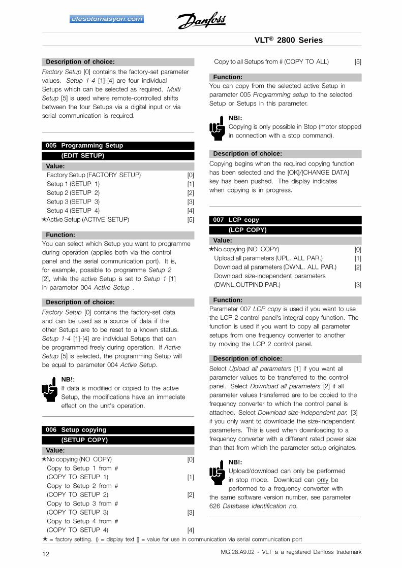
When the frequency converter is in Hand modethe readout will be like:
and the reference can be changed by usingthe following keys:
NB!:Please note, that parameter 020 mayblock the choice of mode.
Automatic motor tuningAutomatic motor tuning (AMT) is performed as follows:
1. In parameter 107 Automatic motor tuningselect data value [2]. "107" will now flash,and "2" will not flash.
2. AMT is activated by pressing start. "107" willnow flash and dashes will move from left toright in the data value field.
3. When "107" appears once more with the datavalue [0], AMT is complete. Press [STOP/RESET]to save the motor data.
4. "107" will then continue to flash with the datavalue [0]. You can now proceed.
NB!:VLT 2880-2882 do not have AMT function.
MG.28.A9.02 - VLT is a registered Danfoss trademark10
VLT® 2800 Series
Pro
gram
min
g
■ Operation & Display
001 Language
(LANGUAGE)
Value:✭ English (ENGLISH) [0]
German (DEUTSCH) [1]French (FRANCAIS) [2]Danish (DANSK) [3]Spanish (ESPANOL) [4]Italian (ITALIANO) [5]
Function:This parameter is used to choose the languageto be shown in the display whenever the LCPcontrol unit is connected.
Description of choice:
There is a choice of the languages shown.The factory setting may vary.
002 Local/remote operation
(OPERATION SITE)
Value:✭ Remote operation (REMOTE) [0]
Local operation (LOCAL) [1]
Function:There is a choice of two different modes of operationof the frequency converter; Remote operation [0] orLocal operation [1]. See also parameter 013 Localcontrol if Local operation [1] is selected.
Description of choice:
If Remote operation [0] is selected, the frequencyconverter is controlled via:1. the control terminals or via serial communication.2. the [START] key. This cannot, however, override
stop commands transmitted via the digitalinputs or via serial communication.
3. the [STOP/RESET] and [JOG] keys, on thecondition that these are active.
If Local operation [1], is selected, the frequencyconverter is controlled via:1. the [START] key. This cannot, however, override
stop commands via the digital inputs (seeparameter 013 Local control).
2. the [STOP/RESET] and [JOG] keys, on thecondition that these are active.
3. the [FWD/REV] key, on the condition that is hasbeen selected as active in parameter 016 Localreversing, and that parameter 013 Local control
is set at Local control and open loop [1] or Localcontrol as parameter 100 [3]. Parameter 200Output frequency range is set at Both directions.
4. parameter 003 Local reference where the referencecan be set using the [+] and [-] keys.
5. an external control command that can beconnected to the digital inputs (see parameter013 Local control).
NB!:The [JOG] and [FWD/REV] keys are locatedon the LCP control unit.
003 Local reference(LOCAL REFERENCE)
Value:Par. 013 Local control must be set to [1] or [2]:0 - fMAX (par. 202) ✭ 50 Hz
Par. 013 Local control must be set to [3] or [4].RefMIN - Ref MAX (par. 204-205) ✭ 0,0
Function:In this parameter, the local reference can be setmanually. The unit of the local reference depends on theconfiguration selected in parameter 100 Configuration.
Description of choice:
In order to protect the local reference, parameter002 Local/remote operation must be set toLocal operation [1]. Local reference cannot beset via serial communication.
004 Active Setup
(ACTIVE SETUP)
Value:Factory Setup (FACTORY SETUP) [0]
✭ Setup 1 (SETUP 1) [1]Setup 2 (SETUP 2) [2]Setup 3 (SETUP 3) [3]Setup 4 (SETUP 4) [4]Multi Setup (MULTI SETUP) [5]
Function:The active parameter Setup is selected here. Allparameters can be programmed in four individualparameter Setups. Shifts between Setups canbe made in this parameter via a digital inputor via serial communication.
✭ = factory setting. () = display text [] = value for use in communication via serial communication port
MG.28.A9.02 - VLT is a registered Danfoss trademark 11
VLT® 2800 Series
Description of choice:
Factory Setup [0] contains the factory-set parametervalues. Setup 1-4 [1]-[4] are four individualSetups which can be selected as required. MultiSetup [5] is used where remote-controlled shiftsbetween the four Setups via a digital input or viaserial communication is required.
005 Programming Setup
(EDIT SETUP)
Value:Factory Setup (FACTORY SETUP) [0]Setup 1 (SETUP 1) [1]Setup 2 (SETUP 2) [2]Setup 3 (SETUP 3) [3]Setup 4 (SETUP 4) [4]
✭ Active Setup (ACTIVE SETUP) [5]
Function:You can select which Setup you want to programmeduring operation (applies both via the controlpanel and the serial communication port). It is,for example, possible to programme Setup 2[2], while the active Setup is set to Setup 1 [1]in parameter 004 Active Setup .
Description of choice:
Factory Setup [0] contains the factory-set dataand can be used as a source of data if theother Setups are to be reset to a known status.Setup 1-4 [1]-[4] are individual Setups that canbe programmed freely during operation. If ActiveSetup [5] is selected, the programming Setup willbe equal to parameter 004 Active Setup.
NB!:If data is modified or copied to the activeSetup, the modifications have an immediateeffect on the unit’s operation.
006 Setup copying
(SETUP COPY)
Value:✭ No copying (NO COPY) [0]
Copy to Setup 1 from #(COPY TO SETUP 1) [1]Copy to Setup 2 from #(COPY TO SETUP 2) [2]Copy to Setup 3 from #(COPY TO SETUP 3) [3]Copy to Setup 4 from #(COPY TO SETUP 4) [4]
Copy to all Setups from # (COPY TO ALL) [5]
Function:You can copy from the selected active Setup inparameter 005 Programming setup to the selectedSetup or Setups in this parameter.
NB!:Copying is only possible in Stop (motor stoppedin connection with a stop command).
Description of choice:
Copying begins when the required copying functionhas been selected and the [OK]/[CHANGE DATA]key has been pushed. The display indicateswhen copying is in progress.
007 LCP copy
(LCP COPY)
Value:✭ No copying (NO COPY) [0]
Upload all parameters (UPL. ALL PAR.) [1]Download all parameters (DWNL. ALL PAR.) [2]Download size-independent parameters(DWNL.OUTPIND.PAR.) [3]
Function:Parameter 007 LCP copy is used if you want to usethe LCP 2 control panel’s integral copy function. Thefunction is used if you want to copy all parametersetups from one frequency converter to anotherby moving the LCP 2 control panel.
Description of choice:
Select Upload all parameters [1] if you want allparameter values to be transferred to the controlpanel. Select Download all parameters [2] if allparameter values transferred are to be copied to thefrequency converter to which the control panel isattached. Select Download size-independent par. [3]if you only want to downloade the size-independentparameters. This is used when downloading to afrequency converter with a different rated power sizethan that from which the parameter setup originates.
NB!:Upload/download can only be performedin stop mode. Download can only beperformed to a frequency converter with
the same software version number, see parameter626 Database identification no.
✭ = factory setting. () = display text [] = value for use in communication via serial communication port
MG.28.A9.02 - VLT is a registered Danfoss trademark12
VLT® 2800 Series
Pro
gram
min
g
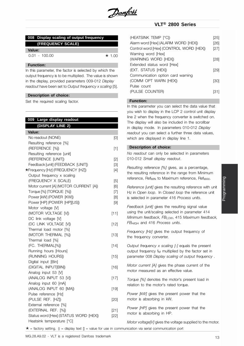
008 Display scaling of output frequency
(FREQUENCY SCALE)
Value:0.01 - 100.00 ✭ 1.00
Function:In this parameter, the factor is selected by which theoutput frequency is to be multiplied. The value is shownin the display, provided parameters 009-012 Displayreadout have been set to Output frequency x scaling [5].
Description of choice:
Set the required scaling factor.
009 Large display readout
(DISPLAY LINE 2)
Value:No readout (NONE) [0]Resulting reference [%](REFERENCE [%]) [1]Resulting reference [unit](REFERENCE [UNIT]) [2]Feedback [unit] (FEEDBACK [UNIT]) [3]
✭ Frequency [Hz] (FREQUENCY [HZ]) [4]Output frequency x scaling(FREQUENCY X SCALE) [5]Motor current [A] (MOTOR CURRENT [A]) [6]Torque [%] (TORQUE [%]) [7]Power [kW] (POWER [KW]) [8]Power [HP] (POWER [HP][US]) [9]Motor voltage [V](MOTOR VOLTAGE [V]) [11]DC link voltage [V](DC LINK VOLTAGE [V]) [12]Thermal load motor [%](MOTOR THERMAL [%]) [13]Thermal load [%](FC. THERMAL[%]) [14]Running hours [Hours](RUNNING HOURS]) [15]Digital input [Bin](DIGITAL INPUT[BIN]) [16]Analog input 53 [V](ANALOG INPUT 53 [V]) [17]Analog input 60 [mA](ANALOG INPUT 60 [MA]) [19]Pulse reference [Hz](PULSE REF. [HZ]) [20]External reference [%](EXTERNAL REF. [%]) [21]Status word [Hex] (STATUS WORD [HEX]) [22]Heatsink temperature [°C]
(HEATSINK TEMP [°C]) [25]Alarm word [Hex] (ALARM WORD [HEX]) [26]Control word [Hex] (CONTROL WORD [HEX]) [27]Warning word [Hex](WARNING WORD [HEX]) [28]Extended status word [Hex](EXT. STATUS [HEX]) [29]Communication option card warning(COMM OPT WARN [HEX]) [30]Pulse count(PULSE COUNTER) [31]
Function:In this parameter you can select the data value thatyou wish to display in the LCP 2 control unit displayline 2 when the frequency converter is switched on.The display will also be included in the scrollbarin display mode. In parameters 010-012 Displayreadout you can select a further three data values,which are displayed in display line 1.
Description of choice:
No readout can only be selected in parameters010-012 Small display readout.
Resulting reference [%] gives, as a percentage,the resulting reference in the range from Minimumreference, RefMIN to Maximum reference, RefMAX.
Reference [unit] gives the resulting reference with unitHz in Open loop. In Closed loop the reference unitis selected in parameter 416 Process units.
Feedback [unit] gives the resulting signal valueusing the unit/scaling selected in parameter 414Minimum feedback, FBLOW, 415 Maximum feedback,FBHIGH and 416 Process units.
Frequency [Hz] gives the output frequency ofthe frequency converter.
Output frequency x scaling [-] equals the presentoutput frequency fM multiplied by the factor set inparameter 008 Display scaling of output frequency .
Motor current [A] gives the phase current of themotor measured as an effective value.
Torque [%] denotes the motor’s present load inrelation to the motor’s rated torque.
Power [kW] gives the present power that themotor is absorbing in kW.
Power [HP] gives the present power that themotor is absorbing in HP.
Motor voltage[V] gives the voltage supplied to the motor.
✭ = factory setting. () = display text [] = value for use in communication via serial communication port
MG.28.A9.02 - VLT is a registered Danfoss trademark 13
VLT® 2800 Series
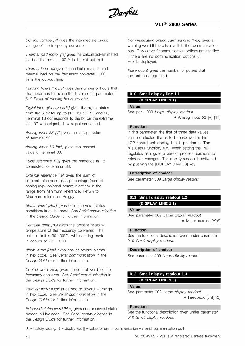
DC link voltage [V] gives the intermediate circuitvoltage of the frequency converter.
Thermal load motor [%] gives the calculated/estimatedload on the motor. 100 % is the cut-out limit.
Thermal load [%] gives the calculated/estimatedthermal load on the frequency converter. 100% is the cut-out limit.
Running hours [Hours] gives the number of hours thatthe motor has tun since the last reset in parameter619 Reset of running hours counter.
Digital input [Binary code] gives the signal statusfrom the 5 digital inputs (18, 19, 27, 29 and 33).Terminal 18 corresponds to the bit on the extremeleft. ‘0’ = no signal, ‘1’ = signal connected.
Analog input 53 [V] gives the voltage valueof terminal 53.
Analog input 60 [mA] gives the presentvalue of terminal 60.
Pulse reference [Hz] gives the reference in Hzconnected to terminal 33.
External reference [%] gives the sum ofexternal references as a percentage (sum ofanalogue/pulse/serial communication) in therange from Minimum reference, RefMIN toMaximum reference, RefMAX.
Status word [Hex] gives one or several statusconditions in a Hex code. See Serial communicationin the Design Guide for further information.
Heatsink temp.[°C] gives the present heatsinktemperature of the frequency converter. Thecut-out limit is 90-100°C, while cutting backin occurs at 70 ± 5°C.
Alarm word [Hex] gives one or several alarmsin hex code. See Serial communication in theDesign Guide for further information.
Control word [Hex] gives the control word for thefrequency converter. See Serial communication inthe Design Guide for further information.
Warning word [Hex] gives one or several warningsin hex code. See Serial communication in theDesign Guide for further information.
Extended status word [Hex] gives one or several statusmodes in Hex code. See Serial communication inthe Design Guide for further information.
Communication option card warning [Hex] gives awarning word if there is a fault in the communicationbus. Only active if communication options are installed.If there are no communication options 0Hex is displayed.
Pulse count gives the number of pulses thatthe unit has registered.
010 Small display line 1.1
(DISPLAY LINE 1.1)
Value:See par. 009 Large display readout
✭ Analog input 53 [V] [17]
Function:In this parameter, the first of three data valuescan be selected that is to be displayed in theLCP control unit display, line 1, position 1. Thisis a useful function, e.g. when setting the PIDregulator, as it gives a view of process reactions toreference changes. The display readout is activatedby pushing the [DISPLAY STATUS] key.
Description of choice:
See parameter 009 Large display readout.
011 Small display readout 1.2
(DISPLAY LINE 1.2)
Value:See parameter 009 Large display readout
✭ Motor current [A][6]
Function:See the functional description given under parameter010 Small display readout.
Description of choice:
See parameter 009 Large display readout.
012 Small display readout 1.3
(DISPLAY LINE 1.3)
Value:See parameter 009 Large display readout
✭ Feedback [unit] [3]
Function:See the functional description given under parameter010 Small display readout.
✭ = factory setting. () = display text [] = value for use in communication via serial communication port
MG.28.A9.02 - VLT is a registered Danfoss trademark14
VLT® 2800 Series
Pro
gram
min
g
Description of choice:
See parameter 009 Large display readout.
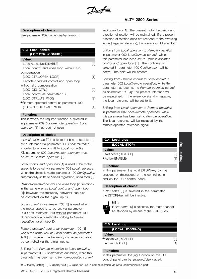
013 Local control(LOC CTRL/CONFIG.)
Value:Local not active (DISABLE) [0]Local control and open loop without slip
compensation(LOC CTRL/OPEN LOOP) [1]Remote-operated control and open loop
without slip compensation(LOC+DIG CTRL) [2]Local control as parameter 100(LOC CTRL/AS P100) [3]
✭ Remote-operated control as parameter 100(LOC+DIG CTRL/AS P100) [4]
Function:This is where the required function is selected if,in parameter 002 Local/remote operation, Localoperation [1] has been chosen.
Description of choice:
If Local not active [0] is selected, it is not possible toset a reference via parameter 003 Local reference.In order to enable a shift to Local not active[0], parameter 002 Local/remote operation mustbe set to Remote operation [0].
Local control and open loop [1] is used if the motorspeed is to be set via parameter 003 Local reference.When this choice is made, parameter 100 Configurationautomatically shifts to Speed regulation, open loop [0].
Remote-operated control and open loop [2] functionsin the same way as Local control and open loop[1]; however, the frequency converter can alsobe controlled via the digital inputs.
Local control as parameter 100 [3] is used whenthe motor speed is to be set via parameter003 Local reference, but without parameter 100Configuration automatically shifting to Speedregulation, open loop [0].
Remote-operated control as parameter 100 [4]works the same way as Local control as parameter100 [3]; however, the frequency converter can alsobe controlled via the digital inputs.
Shifting from Remote operation to Local operationin parameter 002 Local/remote operation, while thisparameter has been set to Remote-operated control
and open loop [1]: The present motor frequency anddirection of rotation will be maintained. If the presentdirection of rotation does not respond to the reversingsignal (negative reference), the reference will be set to 0.
Shifting from Local operation to Remote operationin parameter 002 Local/remote control, whilethis parameter has been set to Remote-operatedcontrol and open loop [1]: The configurationselected in parameter 100 Configuration will beactive. The shift will be smooth.
Shifting from Remote control to Local control inparameter 002 Local/remote operation, while thisparameter has been set to Remote-operated controlas parameter 100 [4]: the present reference willbe maintained. If the reference signal is negative,the local reference will be set to 0.
Shifting from Local operation to Remote operationin parameter 002 Local/remote operation, whilethis parameter has been set to Remote operation:The local reference will be replaced by theremote-operated reference signal.
014 Local stop
(LOCAL STOP)
Value:Not active (DISABLE) [0]
✭ Active (ENABLE) [1]
Function:In this parameter, the local [STOP]-key can beengaged or disengaged on the control paneland on the LCP control panel.
Description of choice:
If Not active [0] is selected in this parameter,the [STOP]-key will be inactive.
NB!:If Not active [0] is selected, the motor cannotbe stopped by means of the [STOP]-key.
015 Local jog
(LOCAL JOGGING)
Value:✭ Not active (DISABLE) [0]
Active (ENABLE) [1]
Function:In this parameter, the jog function on the LCPcontrol panel can be engaged/disengaged.
✭ = factory setting. () = display text [] = value for use in communication via serial communication port
MG.28.A9.02 - VLT is a registered Danfoss trademark 15
VLT® 2800 Series
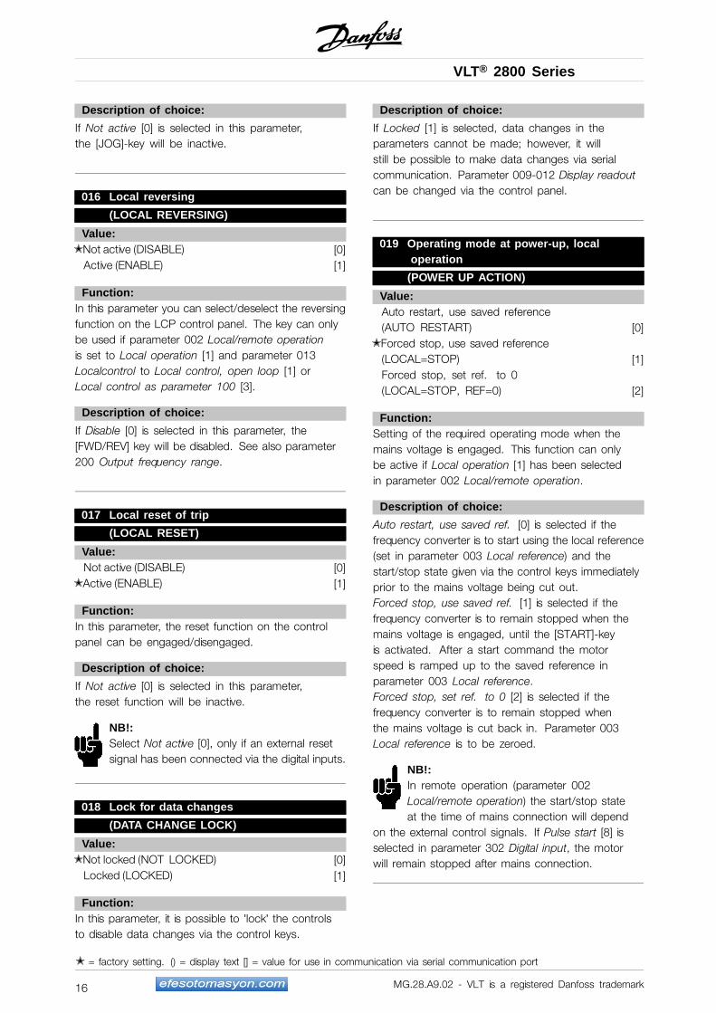
Description of choice:
If Not active [0] is selected in this parameter,the [JOG]-key will be inactive.
016 Local reversing
(LOCAL REVERSING)
Value:✭ Not active (DISABLE) [0]
Active (ENABLE) [1]
Function:In this parameter you can select/deselect the reversingfunction on the LCP control panel. The key can onlybe used if parameter 002 Local/remote operationis set to Local operation [1] and parameter 013Localcontrol to Local control, open loop [1] orLocal control as parameter 100 [3].
Description of choice:
If Disable [0] is selected in this parameter, the[FWD/REV] key will be disabled. See also parameter200 Output frequency range.
017 Local reset of trip
(LOCAL RESET)
Value:Not active (DISABLE) [0]
✭ Active (ENABLE) [1]
Function:In this parameter, the reset function on the controlpanel can be engaged/disengaged.
Description of choice:
If Not active [0] is selected in this parameter,the reset function will be inactive.
NB!:Select Not active [0], only if an external resetsignal has been connected via the digital inputs.
018 Lock for data changes
(DATA CHANGE LOCK)
Value:✭ Not locked (NOT LOCKED) [0]
Locked (LOCKED) [1]
Function:In this parameter, it is possible to ’lock’ the controlsto disable data changes via the control keys.
Description of choice:
If Locked [1] is selected, data changes in theparameters cannot be made; however, it willstill be possible to make data changes via serialcommunication. Parameter 009-012 Display readoutcan be changed via the control panel.
019 Operating mode at power-up, localoperation
(POWER UP ACTION)
Value:Auto restart, use saved reference(AUTO RESTART) [0]
✭ Forced stop, use saved reference(LOCAL=STOP) [1]Forced stop, set ref. to 0(LOCAL=STOP, REF=0) [2]
Function:Setting of the required operating mode when themains voltage is engaged. This function can onlybe active if Local operation [1] has been selectedin parameter 002 Local/remote operation.
Description of choice:
Auto restart, use saved ref. [0] is selected if thefrequency converter is to start using the local reference(set in parameter 003 Local reference) and thestart/stop state given via the control keys immediatelyprior to the mains voltage being cut out.Forced stop, use saved ref. [1] is selected if thefrequency converter is to remain stopped when themains voltage is engaged, until the [START]-keyis activated. After a start command the motorspeed is ramped up to the saved reference inparameter 003 Local reference.Forced stop, set ref. to 0 [2] is selected if thefrequency converter is to remain stopped whenthe mains voltage is cut back in. Parameter 003Local reference is to be zeroed.
NB!:In remote operation (parameter 002Local/remote operation) the start/stop stateat the time of mains connection will depend
on the external control signals. If Pulse start [8] isselected in parameter 302 Digital input, the motorwill remain stopped after mains connection.
✭ = factory setting. () = display text [] = value for use in communication via serial communication port
MG.28.A9.02 - VLT is a registered Danfoss trademark16
VLT® 2800 Series
Pro
gram
min
g
020 Hand operation
(HAND OPERATION)
Value:✭ Not active (DISABLE) [0]
Active (ENABLE) [1]
Function:In this parameter you can select whether it shouldbe possible or not to switch between Auto- andHand mode. In Auto mode the frequency converter iscontrolled by external signals whereas the frequencyconverter in Hand mode is controlled via a localreference directly from the control unit.
Description of choice:
If Not active [0] is selected in this parameter, the Handmode function will be inactive. If Active [1] is selectedyou can switch between Auto- and Hand mode. Forfurther information, see the Control Unit section.
024 Userdefined Quick Menu(USER QUICKMENU)
Value:✭ Not active (DISABLE) [0]
Active (ENABLE) [1]
Function:In this parameter you can select the standardsetup of the Quick menu key on the controlpanel and the LCP 2 control panel.Using this function, in parameter 025 Quick Menusetup the user can select up to 20 parametersfor the Quick Menu key.
Description of choice:
If not active [0] is selected, the standard setupof the Quick Menu key is active.If Active [1] is selected, the user-definedQuick Menu is active.
025 Quick Menu setup
(QUICK MENU SETUP)
Value:[Index 1 - 20] Value: 0 - 999 ✭ 000
Function:In this parameter you define which parameters arerequired in the Quick Menu when parameter 024User-defined Quick Menu is set to Active [1]
´.
Up to 20 parameters can be selected for theuser-defined Quick Menu.
NB!:Please note that this parameter can only be setusing an LCP 2 control panel. See Order form.
Description of choice:
The Quick Menu is set up as follows:1. Select parameter 025 Quick Menu setup
and press [CHANGE DATA].2. Index 1 indicates the first parameter in Quick
Menu. You can scroll between the index numbersusing the [+ / -] keys. Select Index 1.
3. Using [< >] you can scroll between thethree figures. Press the [<] key once adthe last number in the parameter numbercan be selected using the [+ / -] keys.Set Index 1 to 100 for parameter 100 Configuration.
4. Press [OK] when Index 1 has been set to 100.5. Repeat steps 2 - 4 until all parameters required
have been set to the Quick Menu key.6. Press [OK] to complete the Quick Menu setup.If parameter 100 Configuration is selected atIndex 1, Quick Menu will start with this parameterevery time Quick Menu is activated.
Please note that parameter 024 User-defined QuickMenu and parameter 025 Quick Menu setup arereset to the factory setting during initialisation.
✭ = factory setting. () = display text [] = value for use in communication via serial communication port
MG.28.A9.02 - VLT is a registered Danfoss trademark 17
VLT® 2800 Series
■ Load and Motor
100 Configuration
(CONFIGURATION)
Value:✭ Speed control, open loop
(SPEED OPEN LOOP) [0]Speed control, closed loop(SPEED CLOSED LOOP) [1]Process control, closed loop(PROCESS CLOSED LOOP) [3]
Function:This parameter is used to select the configurationto which the frequency converter is to be adapted.This makes adaptation to a given applicationsimple, since the parameters not used in a givenconfiguration are hidden (not active).
Description of choice:
If Speed control, open loop [0] is selected, normalspeed control is obtained (without feedbacksignal) with automatic load and slip compensationto ensure a constant speed at varying loads.Compensations are active, but may be disabled inparameter 134 Load compensation and parameter136 Slip compensation as required.
If Speed control, closed loop [1] is selected, betterspeed accuracy is obtained. A feedback signal mustbe added, and the PID regulator must be set inparameter group 400 Special functions.
If Process control, closed loop [3] is selected, theinternal process regulator is activated to enable precisecontrol of a process in relation to a given processsignal. The process signal can be set to the relevantprocess unit or as a percentage. A feedback signalmust be added from the process and the processregulator must be set in parameter group 400 Specialfunctions. Process closed loop is not active if aDeviceNet card is mounted and Instance 20/70 or21/71 is chosen in parameter 904 Instance types.
101 Torque characteristic
(TORQUE CHARACT)
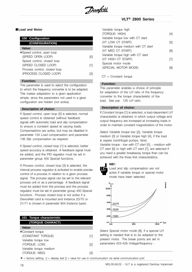
Value:✭ Constant torque
(CONSTANT TORQUE) [1]Variable torque low(TORQUE: LOW) [2]Variable torque medium(TORQUE: MED) [3]
Variable torque high(TORQUE: HIGH) [4]Variable torque low with CT start(VT LOW CT START) [5]Variable torque medium with CT start(VT MED CT START) [6]Variable torque high with CT start(VT HIGH CT START) [7]Special motor mode(SPECIAL MOTOR MODE) [8]
CT = Constant torque
Function:This parameter enables a choice of principlefor adaptation of the U/f ratio of the frequencyconverter to the torque characteristic of theload. See par. 135 U/f ratio.
Description of choice:
If Constant torque [1] is selected, a load-dependent U/fcharacteristic is obtained, in which output voltage andoutput frequency are increased at increasing loads inorder to maintain constant magnetization of the motor.
Select Variable torque low [2], Variable torquemedium [3] or Variable torque high [4], if the loadis square (centrifugal pumps, fans).Variable torque - low with CT start [5], - medium withCT start [6] or high with CT start [7], are selected ifyou need a greater breakaway torque than can beachieved with the three first characteristics.
NB!:Load and slip compensation are notactive if variable torque or special motormode have been selected.
Select Special motor mode [8], if a special U/fsetting is needed that is to be adapted to thepresent motor. The break points are set inparameters 423-428 Voltage/frequency .
✭ = factory setting. () = display text [] = value for use in communication via serial communication port
MG.28.A9.02 - VLT is a registered Danfoss trademark18
VLT® 2800 Series
Pro
gram
min
g
NB!:Please note that if a value set in the nameplateparameters 102-106 is changed, there willbe an automatic change of parameter 108
Stator resistance and 109 Stator reactance.
102 Motor power PM,N
(MOTOR POWER)
Value:0.25 - 22 kW ✭ Depends on unit
Function:Here you must set a power value [kW] PM,N,corresponding to the motor’s rated power. Thefactory sets a rated power value [kW] P M,N,that depends on the type of unit.
Description of choice:
Set a value that matches the nameplate data on themotor. Settings between one size below and onesize over the factory setting are possible.
103 Motor voltage UM,N
(MOTOR VOLTAGE)
Value:For 200 V units: 50 - 999 V ✭ 230 V
For 400 V units: 50 - 999 V ✭ 400 V
Function:This is where to set the rated motor voltageUM,N for either star Y or delta .
Description of choice:
Select a value that corresponds to the nameplatedata on the motor, regardless of the frequencyconverter’s mains voltage.
104 Motor frequency fM,N
(MOTOR FREQUENCY)
Value:24-1000 Hz ✭ 50 Hz
Function:This is where to select the rated motor frequency fM,N.
Description of choice:
Select a value that corresponds to the nameplatedata on the motor.
105 Motor current IM,N
(MOTOR CURRENT)
Value:0,01 - IMAX ✭ Depends on choice of motor
Function:The nominal, rated current of the motor IM,N formspart of the frequency converter calculation of featuressuch as torque and motor thermal protection.
Description of choice:
Set a value that corresponds to the nameplatedata on the motor. Set the motor currentIM,N taking into account whether the motor isstar-connected Y or delta-connected .
106 Rated motor speed
(MOTOR NOM. SPEED)
Value:100 - fM,N x 60 (max. 60000 rpm)✭ Depends on parameter 104 Motor frequency, fM,N
Function:This is where to set the value that correspondsto the rated motor speed nM,N that can beseen from the nameplate data.
Description of choice:
Select a value that corresponds to the nameplatedata on the motor.
NB!:The max. value equals fM,N x 60. fM,N to beset in parameter 104 Motor frequency, fM,N.
107 Automatic motor tuning, AMT
(AUTO MOTOR TUN.)
Value:✭ Optimisation off (AMT OFF) [0]
Optimisation on (AMT START) [2]
Function:
NB!:AMT is not possible on VLT 2880-82.
Automatic motor tuning is an algorithm that measuresstator resistance RS without the motor axle turning.This means that the motor is not delivering any torque.AMT can be used with benefit when initialising unitswhere the user wishes to optimise adjustment of
✭ = factory setting. () = display text [] = value for use in communication via serial communication port
MG.28.A9.02 - VLT is a registered Danfoss trademark 19
VLT® 2800 Series
the frequency converter to the motor being used.This is used in particular when the factory settingdoes not sufficiently cover the motor.
For the best possible tuning of the frequency converterit is recommended that AMT is performed on acold motor. It should be noted that repeated AMTruns can cause heating of the motor, resultingin an increase in the stator resistance RS. As arule, however, this is not critical.
AMT is performed as follows:
Start AMT:1. Give a STOP signal.2. Parameter 107 Automatic motor tuning is set
at value [2] Optimisation on.3. A START signal is given and parameter 107
Automatic motor tuning is reset to [0] whenAMT has been completed.
Complete AMT:AMT is completed by giving a RESET signal.Parameter 108 Stator resistance, Rs is updatedwith the optimised value.
Interrupting AMT:AMT can be interrupted during the optimisationprocedure by giving a STOP signal.
When using the AMT function the followingpoints should be observed:- For AMT to be able to define the motor parameters
as well as possible, the correct type plate data forthe motor connected to the frequency convertermust be keyed into parameters 102 to 106.
- Alarms will appear in the display if faults ariseduring tuning of the motor.
- As a rule the AMT function will be able to measurethe RS values for motors that are 1-2 times larger orsmaller than the frequency converter’s nominal size.
- If you wish to interrupt automatic motor tuning,press the [STOP/RESET] key.
NB!:AMT may not be performed on motorsconnected in parallel, nor may setup changesbe made while AMT is running.
The procedure for AMT controlled from the SLCP:See section entitled Control unit.
Description of choice:
Select Optimisation on [2] if you want the frequencyconverter to perform automatic motor tuning.
108 Stator resistance RS
(STATOR RESISTAN)
Value:0.000 - X.XXX
✭ Depends on choice of motor
Function:After setting of parameters 102-106 Nameplate data,a number of adjustments of various parameters iscarried out automatically, including stator resistanceRS. A manually entered RS must apply to a coldmotor. The shaft performance can be improved byfine-tuning RS and XS, see procedure below.
NB!:Parameters 108 Stator resistance RS and 109Stator reactance XS are normally not to bechanged if nameplate data has been set.
Description of choice:
RS can be set as follows:
1. Use the factory settings of RS which thefrequency converter itself chooses on the basisof the motor nameplate data.
2. The value is stated by the motor supplier.3. The value is obtained through manual
measurements: RS can be calculated by measuringthe resistance RPHASE-PHASE between two phaseterminals. Where RPHASE-PHASE is lower than 1-2Ohms (typical for motors > 5.5 kW, 400 V), a specialOhm-meter should be used (Thomson-bridge orsimilar). RS = 0.5 x RPHASE-PHASE.
4. RS is set automatically when AMT hasbeen completed. See parameter 107Auto motor adaption.
109 Stator reactance XS
(STATOR REACTANCE)
Value:0.00 - X,XX
✭ Depends on choice of motor
Function:After setting of parameters 102-106 Nameplate data,a number of adjustments of various parametersare made automatically, including stator reactanceXS. The shaft performance can be improved byfine-tuning RS and XS, see procedure below.
Description of choice:
XS can be set as follows:
1. The value is stated by the motor supplier.
✭ = factory setting. () = display text [] = value for use in communication via serial communication port
MG.28.A9.02 - VLT is a registered Danfoss trademark20
VLT® 2800 Series
Pro
gram
min
g
2. The value is obtained through manualmeasurements XS is obtained by connecting amotor to mains and measuring the phase-phasevoltage U M and the idle current .
XL: See parameter 142.
3. Use the factory settings of XS which thefrequency converter itself chooses on the basisof the motor nameplate data.
117 Resonance damping
(RESONANCE DAMPING)
Value:OFF - 100% [OFF - 100]
✭ OFF % [OFF]
Function:It is possible to optimise the resonance dampingin CT mode. The grade of the influence isadjusted in this parameter.The value may be set between 0% (OFF) and 100%.100% corresponds to 50% reduction of U/F ratio.Default value is OFF.
Internal settings (fixed):The resonance filter is active from 10% ofnominal speed and above.In this case 5Hz and above.Speed to go from 0 to nominal flux level: 500msSpeed to go from nominal to 0 flux level: 500ms
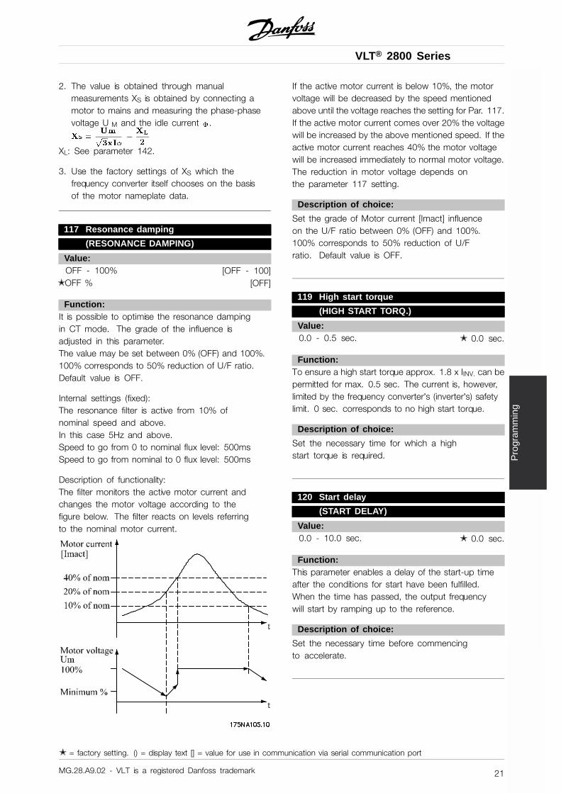
Description of functionality:The filter monitors the active motor current andchanges the motor voltage according to thefigure below. The filter reacts on levels referringto the nominal motor current.
If the active motor current is below 10%, the motorvoltage will be decreased by the speed mentionedabove until the voltage reaches the setting for Par. 117.If the active motor current comes over 20% the voltagewill be increased by the above mentioned speed. If theactive motor current reaches 40% the motor voltagewill be increased immediately to normal motor voltage.The reduction in motor voltage depends onthe parameter 117 setting.
Description of choice:
Set the grade of Motor current [Imact] influenceon the U/F ratio between 0% (OFF) and 100%.100% corresponds to 50% reduction of U/Fratio. Default value is OFF.
119 High start torque
(HIGH START TORQ.)
Value:0.0 - 0.5 sec. ✭ 0.0 sec.
Function:To ensure a high start torque approx. 1.8 x IINV. can bepermitted for max. 0.5 sec. The current is, however,limited by the frequency converter’s (inverter’s) safetylimit. 0 sec. corresponds to no high start torque.
Description of choice:
Set the necessary time for which a highstart torque is required.
120 Start delay
(START DELAY)
Value:0.0 - 10.0 sec. ✭ 0.0 sec.
Function:This parameter enables a delay of the start-up timeafter the conditions for start have been fulfilled.When the time has passed, the output frequencywill start by ramping up to the reference.
Description of choice:
Set the necessary time before commencingto accelerate.
✭ = factory setting. () = display text [] = value for use in communication via serial communication port
MG.28.A9.02 - VLT is a registered Danfoss trademark 21
VLT® 2800 Series
121 Start function(START FUNCTION)
Value:DC hold during start delay time(DC HOLD/DELAY TIME) [0]DC brake during start delay time(DC BRAKE/DELAY TIME) [1]
✭ Coasting during start delay time(COAST/DELAY TIME) [2]Start frequency/voltage clockwise(CLOCKWISE OPERATION) [3]Start frequency/voltage in reference direction(VERTICAL OPERATION) [4]
Function:This is where to choose the required mode during thestart delay time (parameter 120 Start delay time).
Description of choice:
Select DC hold during start delay time [0] to energizethe motor with a DC hold voltage during the start delaytime. Set voltage in parameter 137 DC hold voltage.
Choose DC brake during start delay time [1] to energizethe motor with a DC brake voltage during the start delaytime. Set voltage in parameter 132 DC brake voltage.
Choose Coasting during start delay time [2] and themotor will not be controlled by the frequency converterduring the start delay time (inverter turned off).
Choose Start frequency/voltage clockwise [3] toobtain the function described in parameter 130Start frequency and 131 Voltage at start during startdelay time. Regardless of the value assumed bythe reference signal, the output frequency equalsthe setting in parameter 130 Start frequency andthe output voltage will correspond to the settingin parameter 131 Voltage at start .This functionality is typically used in hoist applications.It is used in particular in applications in which a coneanchor motor is applied, where the direction of rotationis to start clockwise followed by the reference direction.
Select Start frequency/voltage in reference direction[4] to obtain the function described in parameter130 Start frequency and 131 Voltage at startduring the start delay time.The direction of rotation of the motor will alwaysfollow in the reference direction. If the reference signalequals zero, the output frequency will equal 0 Hz,while the output voltage will correspond to the settingin parameter 131 Voltage at start. If the referencesignal is different from zero, the output frequency willequal parameter 130 Start frequency and the output
voltage will equal parameter 131 Voltage at start. Thisfunctionality is used typically for hoist applications withcounterweight. It is used in particular for applicationsin which a cone anchor motor is applied. The coneanchor motor can break away using parameter 130Start frequency and parameter 131 Voltage at start.
122 Function at stop
(FUNCTION AT STOP)
Value:✭ Coasting (COAST) [0]
DC hold (DC HOLD) [1]
Function:This is where to choose the function of the frequencyconverter after the output frequency has becomelower than the value in parameter 123 The min.frequency for activation of function at stop or aftera stop command and when the output frequencyhas been ramped down to 0 Hz.
Description of choice:
Select Coasting [0] if the frequency converter is to’let go’ of the motor (inverter turned off).
Select DC hold [1] if parameter 137 DC holdvoltage is to be activated.
123 Min. frequency for activation offunction at stop
(MIN.F.FUNC.STOP)
Value:0,1 - 10 Hz ✭ 0,1 Hz
Function:In this parameter, the output frequency is set atwhich the function selected in parameter 122Function at stop is to be activated.
Description of choice:
Set the required output frequency.
NB!:If parameter 123 is set higher than parameter130, then the start delay function (parameter120 and 121) will be skipped.
✭ = factory setting. () = display text [] = value for use in communication via serial communication port
MG.28.A9.02 - VLT is a registered Danfoss trademark22
VLT® 2800 Series
Pro
gram
min
g
NB!:If parameter 123 is set too high, and DChold has been chosen in parameter 122,the output frequency will jump to the value
in parameter 123 without ramping up. This maycause an overcurrent warning / alarm.
126 DC brake time(DC BRAKING TIME)
Value:0 - 60 sec. ✭ 10 sec
Function:In this parameter, the DC brake time is set at whichparameter 132 DC brake voltage is to be active.
Description of choice:
Set the required time.
127 DC brake cut-in frequency
(DC BRAKE CUT-IN)
Value:0.0 (OFF) - par. 202
Output frequency high limit, fMAX ✭ OFF
Function:In this parameter, the DC brake cut-in frequencyis set at which the DC brake is to be activatedin connection with a stop command.
Description of choice:
Set the required frequency.
128 Thermal motor protection
(MOT.THERM PROTEC)
Value:✭ No protection (NO PROTECTION) [0]
Thermistor warning(THERMISTOR WARN) [1]Thermistor trip (THERMISTOR TRIP) [2]ETR warning 1 (ETR WARNING 1) [3]ETR trip 1 (ETR TRIP 1) [4]ETR warning 2 (ETR WARNING 2) [5]ETR trip 2 (ETR TRIP 2) [6]ETR warning 3 (ETR WARNING 3) [7]ETR trip 3 (ETR TRIP 3) [8]ETR warning 4 (ETR WARNING 4) [9]ETR trip 4 (ETR TRIP 4) [10]
Function:The frequency converter can monitor the motortemperature in two different ways:
- Via a PTC thermistor that is mounted on the motor.The thermistor is connected between terminal 50(+10V) and one of the digital input terminals 18, 19,27 or 29. See parameter 300 Digital inputs.
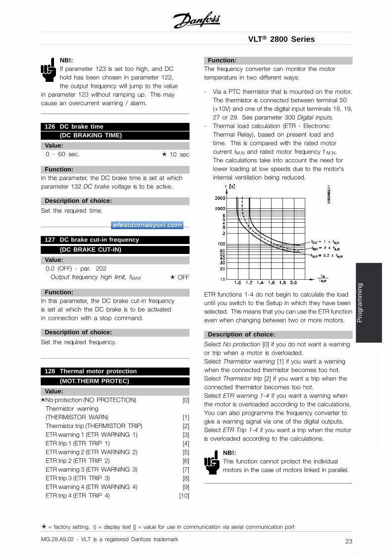
- Thermal load calculation (ETR - ElectronicThermal Relay), based on present load andtime. This is compared with the rated motorcurrent IM,N and rated motor frequency f M,N.The calculations take into account the need forlower loading at low speeds due to the motor’sinternal ventilation being reduced.
ETR functions 1-4 do not begin to calculate the loaduntil you switch to the Setup in which they have beenselected. This means that you can use the ETR functioneven when changing between two or more motors.
Description of choice:
Select No protection [0] if you do not want a warningor trip when a motor is overloaded.Select Thermistor warning [1] if you want a warningwhen the connected thermistor becomes too hot.Select Thermistor trip [2] if you want a trip when theconnected thermistor becomes too hot.Select ETR warning 1-4 if you want a warning whenthe motor is overloaded according to the calculations.You can also programme the frequency converter togive a warning signal via one of the digital outputs.Select ETR Trip 1-4 if you want a trip when the motoris overloaded according to the calculations.
NB!:This function cannot protect the individualmotors in the case of motors linked in parallel.
✭ = factory setting. () = display text [] = value for use in communication via serial communication port
MG.28.A9.02 - VLT is a registered Danfoss trademark 23
VLT® 2800 Series
130 Start frequency
(START FREQUENCY)
Value:0.0 - 10.0 Hz ✭ 0.0 Hz
Function:The start frequency is active for the time set inparameter 120 Start delay, after a start command.The output frequency will ’jump’ to the next presetfrequency. Certain motors, such as conical anchormotors, need an extra voltage/start frequency(boost) at start to disengage the mechanical brake.To achieve this parameters 130 Start frequencyand 131 Initial voltage are used.
Description of choice:
Set the required start frequency. It is a preconditionthat parameter 121 Start function, is set toStart frequency/voltage clockwise [3] or Startfrequency voltage in reference direction [4] andthat in parameter 120 Start delay a time is setand a reference signal is present.
NB!:If parameter 123 is set higher than parameter130, the start delay function (parameter120 and 121) will be skipped.
131 Initial voltage
(INITIAL VOLTAGE)
Value:0.0 - 200.0 V ✭ 0.0 V
Function:Initial voltage is active for the time set in parameter120 Start delay , after a start command. Thisparameter can be used for example for lifting/droppingapplications (conical anchor motors).
Description of choice:
Set the required voltage necessary to cut out themechanical brake. It is assumed that parameter121 Start function, is set to Start frequency/voltageclockwise [3] or Start frequency/voltage in referencedirection [4] and that in parameter 120 Start delay atime is set, and that a reference signal is present.
132 DC brake voltage
(DC BRAKE VOLTAGE)
Value:0 - 100% of max. DC brake voltage ✭ 0%
Function:In this parameter, the DC brake voltage is set which isto be activated at stop when the DC brake frequencyset in parameter 127 DC brake cut-in frequency isreached, or if DC braking inverse is active via a digitalinput or via serial communication. Subsequently,the DC brake voltage will be active for the timeset in parameter 126 DC brake time.
Description of choice:
To be set as a percentage value of the max. DCbrake voltage, which depends on the motor.
133 Start voltage
(START VOLTAGE)
Value:0.00 - 100.00 V ✭ Depends on unit
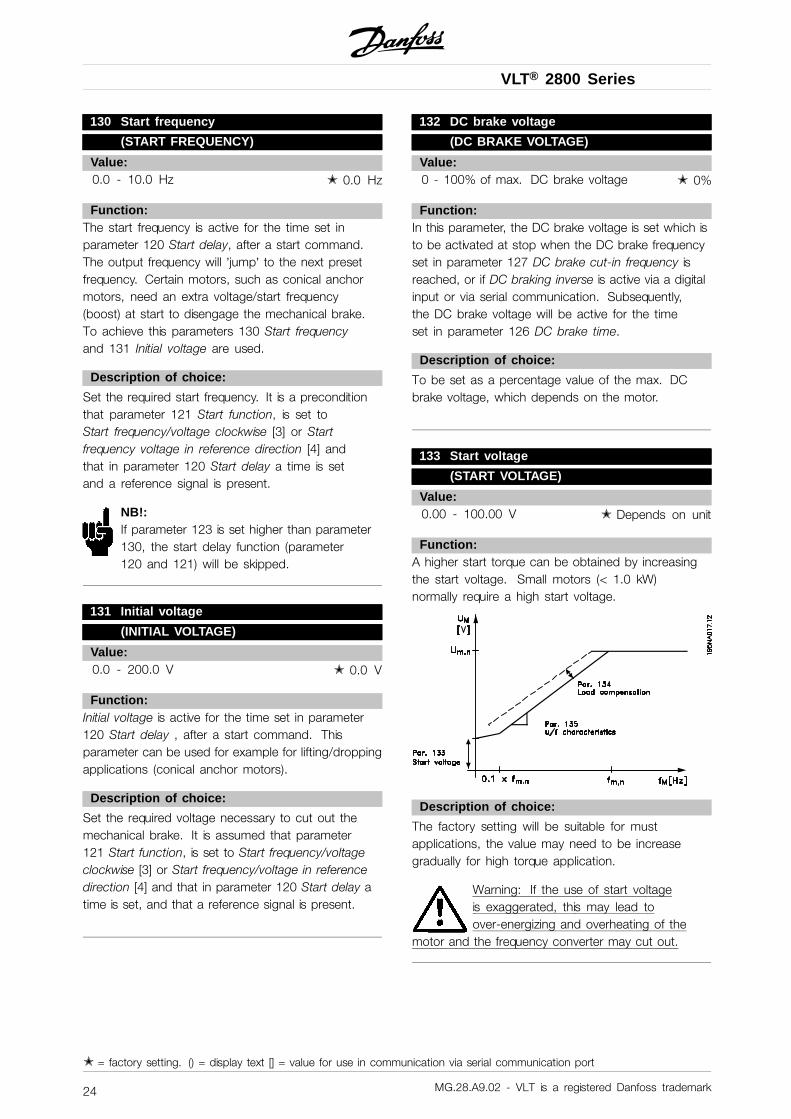
Function:A higher start torque can be obtained by increasingthe start voltage. Small motors (< 1.0 kW)normally require a high start voltage.
Description of choice:
The factory setting will be suitable for mustapplications, the value may need to be increasegradually for high torque application.
Warning: If the use of start voltageis exaggerated, this may lead toover-energizing and overheating of the
motor and the frequency converter may cut out.
✭ = factory setting. () = display text [] = value for use in communication via serial communication port
MG.28.A9.02 - VLT is a registered Danfoss trademark24
VLT® 2800 Series
Pro
gram
min
g
134 Load compensation
(LOAD COMPENSATIO)
Value:0.0 - 300.0% ✭ 100.0%
Function:In this parameter, the load characteristic is set. Byincreasing the load compensation, the motor is given anextra voltage and frequency supplement at increasingloads. This is used e.g. in motors/applications inwhich there is a big difference between the full-loadcurrent and idle-load current of the motor.
NB!:If this value is set too high, the frequencyconverter may cut out because of overcurrent.
Description of choice:
If the factory setting is not adequate, loadcompensation must be set to enable the motorto start at the given load.
Warning: Should be set to 0% inconnection with synchronous andparallel-coupled motors and in the
case of quick load changes. Too high loadcompensation may lead to instability.
135 U/f-ratio(U/F RATIO)
Value:0.00 - 20.00 at Hz ✭ Depends on unit
Function:This parameter enables a shift in the ratio betweenoutput voltage (U) and output frequency (f) linearly,so as to ensure correct energizing of the motor andthus optimum dynamics, accuracy and efficiency.The U/f-ratio only affects the voltage characteristicif a selection has been made of Constant torque[1] parameter 101 Torque characteristic.
Description of choice:
The U/f-ratio is only to be changed if it is notpossible to set the correct motor data in parameter102-109. The value programmed in the factorysettings is based on idle operation.
136 Slip compensation
(SLIP COMP.)
Value:-500 - +500% of rated slip compensation
✭ 100%
Function:Slip compensation is calculated automatically, onthe basis of such data as the rated motor speednM,N. In this parameter, the slip compensation can befine-tuned, thereby compensating for tolerances onthe value for n M,N. Slip compensation is only active ifa selection has been made of Speedregulation, openloop [0] in parameter 100 Configuration and Constanttorque [1] in parameter 101 Torque characteristic.
Description of choice:
Key in a % value.
137 DC hold voltage
(DC HOLD VOLTAGE)
Value:0 - 100% of max. DC hold voltage ✭ 0%
Function:This parameter is used to keep the motor(holding torque) at start/stop.
Description of choice:
This parameter can only be used if a selection hasbeen made of DC hold in parameter 121 Startfunction or 122 Function at stop . To be set asa percentage value of the max. DC hold voltage,which depends on the choice of motor.
138 Brake cut out value(BRAKE CUT OUT)
Value:0.5 - 132.0/1000.0 Hz ✭ 3.0 Hz
Function:Here you can select the frequency at which the externalbrake is released, via the output defined in parameter323 Relay output 1-3 or 341 Digital output, terminal 46.
Description of choice:
Set the required frequency.
✭ = factory setting. () = display text [] = value for use in communication via serial communication port
MG.28.A9.02 - VLT is a registered Danfoss trademark 25
VLT® 2800 Series
139 Brake cut in frequency
(BRAKE CUT IN)
Value:0.5 - 132.0/1000.0 Hz ✭ 3.0 Hz
Function:Here you can select the frequency at which theexternal brake is activated; this takes place viathe output defined in parameter 323 Relay output1-3 or 341 Digital output terminal 46.
Description of choice:
Set the required frequency.
140 Current, minimum value
(CURRENT MIN VAL)
Value:0 % - 100 % of inverter output current ✭ 0 %
Function:This is where the user selects the minimum motorcurrent running for the mechanical brake to bereleased. Current monitoring is only active from stopuntil the point when the brake is released.
Description of choice:
This is an extra safety precaution, aimed atguaranteeing that the load is not lost during startof a lifting/lowering operation.
142 Leakage reactance XL
(LEAK. REACTANCE)
Value:0.000 - XXX,XXX
✭ Depends on choice of motorXL is sum of rotor and stator leakage reactance.
Function:After setting of parameters 102-106 Nameplate data,a number of adjustments of various parameter ismade automatically, including the leakage reactanceXL. The shaft performance can be improved byfine-tuning the leakage reactance XL.
NB!:Parameter 142 The leakage reactance XL isnormally not to be changed if the nameplatedata have been set, parameters 102-106.
Description of choice:
XL can be set as follows:
1. The value is stated by the motor supplier.2. Use the factory settings of XL which the
frequency converter itself chooses on the basisof the motor nameplate data.
143 Internal fan control(FAN CONTROL)
Value:✭ Automatic (AUTOMATIC) [0]
Always switched on (ALWAYS ON) [1]Always switched off (ALWAYS OFF) [2]
Function:This parameter can be set so that the internal fan isautomatically switched on and off. You can also setthe internal fan to be permanently switched on or off.
Description of choice:
If Automatic [0] is selected, the internal fan is switchedon or off depending on the ambient temperatureand the loading of the frequency converter.If Always switched on [1] Always switchedoff [2] are selected, the internal fan will bepermanently switched on or off.
NB!:If Always switched off [2] is selected incombination with high switch frequency,long motor cables or high output power, the
frequency converter’s life span is reduced.
144 Gain AC brake(GAIN AC BRAKE)
Value:1.00 - 1.50 ✭ 1.30
Function:This parameter is used to set the AC brake. Using par.144 it is possible to adjust the size of the generatortorque that can be applied to the motor without theintermediate circuit voltage exceeding the warning level.
Description of choice:
The value is increased if a greater possible braketorque is required. If 1.0 is selected, this correspondsto the AC brake being inactive.
✭ = factory setting. () = display text [] = value for use in communication via serial communication port
MG.28.A9.02 - VLT is a registered Danfoss trademark26
VLT® 2800 Series
Pro
gram
min
g
NB!:If the value in par. 144 is increased, themotor current will simultaneously increasesignificantly when generator loads are applied.
The parameter should therefore only be changed ifit is guaranteed during measurement that the motorcurrent in all operating situations will never exceed themaximum permitted current in the motor. Please note:that the current cannot be read out from the display.
146 Reset voltage vector
(RESET VECTOR)
Value:*Off (OFF) [0]Reset (RESET) [1]
Function:When the voltage vector is reset it is set to the samestarting point each time a new process commences.
Description of choice:
Select reset (1) when running unique processes eachtime they arise. This will enable repetitive precisionwhen stopping to be improved. Select Off (0) forexample for lifting/lowering operations or synchronousmotors. It is an advantage that the motor and thefrequency converter are always synchronized.
✭ = factory setting. () = display text [] = value for use in communication via serial communication port
MG.28.A9.02 - VLT is a registered Danfoss trademark 27
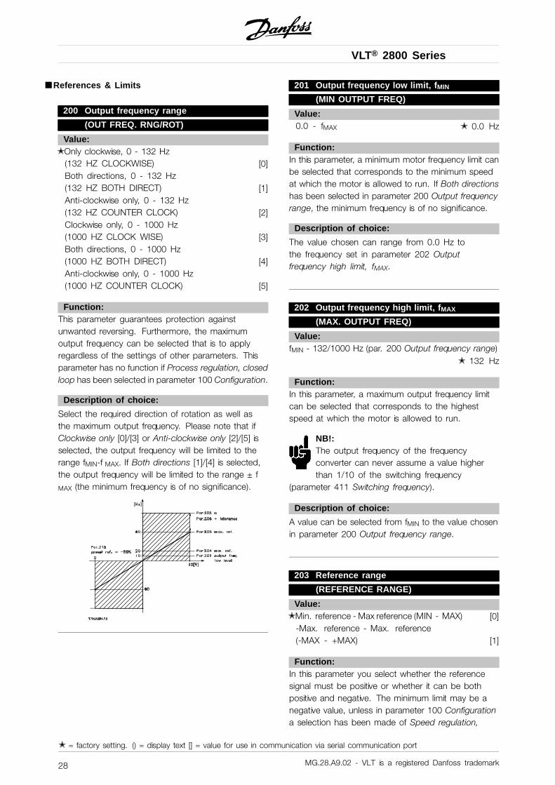
VLT® 2800 Series
■ References & Limits
200 Output frequency range
(OUT FREQ. RNG/ROT)
Value:✭ Only clockwise, 0 - 132 Hz
(132 HZ CLOCKWISE) [0]Both directions, 0 - 132 Hz(132 HZ BOTH DIRECT) [1]Anti-clockwise only, 0 - 132 Hz(132 HZ COUNTER CLOCK) [2]Clockwise only, 0 - 1000 Hz(1000 HZ CLOCK WISE) [3]Both directions, 0 - 1000 Hz(1000 HZ BOTH DIRECT) [4]Anti-clockwise only, 0 - 1000 Hz(1000 HZ COUNTER CLOCK) [5]
Function:This parameter guarantees protection againstunwanted reversing. Furthermore, the maximumoutput frequency can be selected that is to applyregardless of the settings of other parameters. Thisparameter has no function if Process regulation, closedloop has been selected in parameter 100 Configuration.
Description of choice:
Select the required direction of rotation as well asthe maximum output frequency. Please note that ifClockwise only [0]/[3] or Anti-clockwise only [2]/[5] isselected, the output frequency will be limited to therange fMIN-f MAX. If Both directions [1]/[4] is selected,the output frequency will be limited to the range ± f
MAX (the minimum frequency is of no significance).
201 Output frequency low limit, fMIN
(MIN OUTPUT FREQ)
Value:0.0 - fMAX ✭ 0.0 Hz
Function:In this parameter, a minimum motor frequency limit canbe selected that corresponds to the minimum speedat which the motor is allowed to run. If Both directionshas been selected in parameter 200 Output frequencyrange, the minimum frequency is of no significance.
Description of choice:
The value chosen can range from 0.0 Hz tothe frequency set in parameter 202 Outputfrequency high limit, fMAX.
202 Output frequency high limit, fMAX
(MAX. OUTPUT FREQ)
Value:fMIN - 132/1000 Hz (par. 200 Output frequency range)
✭ 132 Hz
Function:In this parameter, a maximum output frequency limitcan be selected that corresponds to the highestspeed at which the motor is allowed to run.
NB!:The output frequency of the frequencyconverter can never assume a value higherthan 1/10 of the switching frequency
(parameter 411 Switching frequency).
Description of choice:
A value can be selected from fMIN to the value chosenin parameter 200 Output frequency range.
203 Reference range
(REFERENCE RANGE)
Value:✭ Min. reference - Max reference (MIN - MAX) [0]
-Max. reference - Max. reference(-MAX - +MAX) [1]
Function:In this parameter you select whether the referencesignal must be positive or whether it can be bothpositive and negative. The minimum limit may be anegative value, unless in parameter 100 Configurationa selection has been made of Speed regulation,
✭ = factory setting. () = display text [] = value for use in communication via serial communication port
MG.28.A9.02 - VLT is a registered Danfoss trademark28
VLT® 2800 Series
Pro
gram
min
g
closed loop. You should select Min ref. - Max. ref.[0], if Process regulation, closed loop [3] has beenselected in parameter 100 Configuration.
Description of choice:
Select the required range.
204 Minimum reference, Ref MIN
(MIN.REFERENCE)
Value:Par. 100 Config. = Open loop [0].-100,000.000 - par. 205 RefMAX ✭ 0.000 Hz
Par. 100 Config. = Closed loop [1]/[3].-Par. 414 Minimum feedback - par. 205 RefMAX
✭ 0.000 rpm/par 416
Function:Minimum reference is an expression of the minimumpossible value of the total of all references. If inparameter 100 Configuration, Speed regulation,closed loop [1] or Process regulation, closed loop[3] is selected, the minimum reference is limitedby parameter 414 Minimum feedback. Minimumreference is ignored if the local reference is active.
The reference unit can be defined fromthe following table:
Par. 100 Configuration UnitOpen loop [0] HzSpeed reg, closed loop [1] rpmProcess reg, closed loop [3] Par. 416
Description of choice:
The minimum reference is preset if the motorhas to run at a minimum speed, regardless ofwhether the resulting reference is 0.
205 Maximum reference, RefMAX
(MAX.REFERENCE)
Value:Par. 100 Config. = Open loop [0].Par. 204 RefMIN - 1000.000 Hz ✭ 50.000 Hz
Par. 100 Config. = Closed loop [1]/[3].Par. 204 RefMIN - Par. 415 Max. feedback
✭ 50.000 rpm/par 416
Function:The maximum reference gives the highest valuethat can be assumed by the sum of all references.If Closed loop [1]/[3] is selected in parameter 100Configuration the maximum reference cannot exceedthe value in parameter 415 Maximum feedback.Maximum reference is ignored if the localreference is active.
The reference unit can be defined fromthe following table:
Par. 100 Configuration UnitOpen loop [0] HzSpeed reg, closed loop [1] rpmProcess reg, closed loop [3] Par. 416
Description of choice:
Maximum reference is set, if the speed of themotor is to be max. the set value, regardlessof the whether the resulting reference is greaterthan the maximum reference.
206 Ramp type
(RAMP TYPE)
Value:✭ Linear (LINEAR) [0]
Sin shaped (SIN SHAPED) [1]Sin2 shaped (S-SHAPED 2) [2]
Function:You can choose between a linear, an S-shapedand an S2 ramp process.
Description of choice:
Select the required ramp type depending on therequired acceleration/deceleration process.
✭ = factory setting. () = display text [] = value for use in communication via serial communication port
MG.28.A9.02 - VLT is a registered Danfoss trademark 29
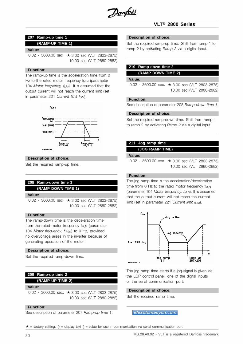
VLT® 2800 Series
207 Ramp-up time 1
(RAMP-UP TIME 1)
Value:0.02 - 3600.00 sec ✭ 3.00 sec (VLT 2803-2875)
10.00 sec (VLT 2880-2882)
Function:The ramp-up time is the acceleration time from 0Hz to the rated motor frequency fM,N (parameter104 Motor frequency, fM,N). It is assumed that theoutput current will not reach the current limit (setin parameter 221 Current limit ILIM).
Description of choice:
Set the required ramp-up time.
208 Ramp-down time 1
(RAMP DOWN TIME 1)
Value:0.02 - 3600.00 sec ✭ 3.00 sec (VLT 2803-2875)
10.00 sec (VLT 2880-2882)
Function:The ramp-down time is the deceleration timefrom the rated motor frequency fM,N (parameter104 Motor frequency, f M,N) to 0 Hz, providedno overvoltage arises in the inverter because ofgenerating operation of the motor.
Description of choice:
Set the required ramp-down time.
209 Ramp-up time 2
(RAMP UP TIME 2)
Value:0.02 - 3600.00 sec. ✭ 3.00 sec (VLT 2803-2875)
10.00 sec (VLT 2880-2882)
Function:See description of parameter 207 Ramp-up time 1.
Description of choice:
Set the required ramp-up time. Shift from ramp 1 toramp 2 by activating Ramp 2 via a digital input.
210 Ramp-down time 2
(RAMP DOWN TIME 2)
Value:0.02 - 3600.00 sec. ✭ 3.00 sec (VLT 2803-2875)
10.00 sec (VLT 2880-2882)
Function:See description of parameter 208 Ramp-down time 1.
Description of choice:
Set the required ramp-down time. Shift from ramp 1to ramp 2 by activating Ramp 2 via a digital input.
211 Jog ramp time
(JOG RAMP TIME)
Value:0.02 - 3600.00 sec. ✭ 3.00 sec (VLT 2803-2875)
10.00 sec (VLT 2880-2882)
Function:The jog ramp time is the acceleration/decelerationtime from 0 Hz to the rated motor frequency fM,N
(parameter 104 Motor frequency, fM,N). It is assumedthat the output current will not reach the currentlimit (set in parameter 221 Current limit ILIM).
The jog ramp time starts if a jog-signal is given viathe LCP control panel, one of the digital inputsor the serial communication port.
Description of choice:
Set the required ramp time.
✭ = factory setting. () = display text [] = value for use in communication via serial communication port
MG.28.A9.02 - VLT is a registered Danfoss trademark30
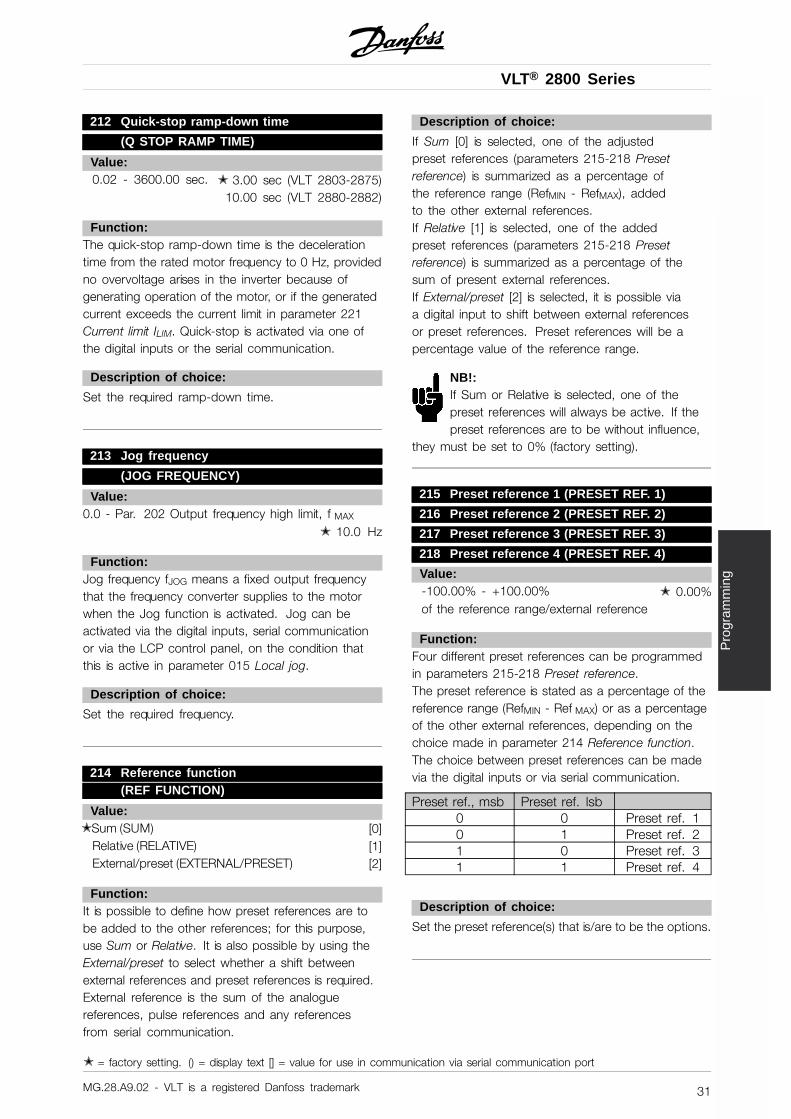
VLT® 2800 Series
Pro
gram
min
g
212 Quick-stop ramp-down time
(Q STOP RAMP TIME)
Value:0.02 - 3600.00 sec. ✭ 3.00 sec (VLT 2803-2875)
10.00 sec (VLT 2880-2882)
Function:The quick-stop ramp-down time is the decelerationtime from the rated motor frequency to 0 Hz, providedno overvoltage arises in the inverter because ofgenerating operation of the motor, or if the generatedcurrent exceeds the current limit in parameter 221Current limit ILIM. Quick-stop is activated via one ofthe digital inputs or the serial communication.
Description of choice:
Set the required ramp-down time.
213 Jog frequency
(JOG FREQUENCY)
Value:0.0 - Par. 202 Output frequency high limit, f MAX
✭ 10.0 Hz
Function:Jog frequency fJOG means a fixed output frequencythat the frequency converter supplies to the motorwhen the Jog function is activated. Jog can beactivated via the digital inputs, serial communicationor via the LCP control panel, on the condition thatthis is active in parameter 015 Local jog.
Description of choice:
Set the required frequency.
214 Reference function(REF FUNCTION)
Value:✭ Sum (SUM) [0]
Relative (RELATIVE) [1]External/preset (EXTERNAL/PRESET) [2]
Function:It is possible to define how preset references are tobe added to the other references; for this purpose,use Sum or Relative. It is also possible by using theExternal/preset to select whether a shift betweenexternal references and preset references is required.External reference is the sum of the analoguereferences, pulse references and any referencesfrom serial communication.
Description of choice:
If Sum [0] is selected, one of the adjustedpreset references (parameters 215-218 Presetreference) is summarized as a percentage ofthe reference range (RefMIN - RefMAX), addedto the other external references.If Relative [1] is selected, one of the addedpreset references (parameters 215-218 Presetreference) is summarized as a percentage of thesum of present external references.If External/preset [2] is selected, it is possible viaa digital input to shift between external referencesor preset references. Preset references will be apercentage value of the reference range.
NB!:If Sum or Relative is selected, one of thepreset references will always be active. If thepreset references are to be without influence,
they must be set to 0% (factory setting).
215 Preset reference 1 (PRESET REF. 1)
216 Preset reference 2 (PRESET REF. 2)
217 Preset reference 3 (PRESET REF. 3)
218 Preset reference 4 (PRESET REF. 4)
Value:-100.00% - +100.00% ✭ 0.00%of the reference range/external reference
Function:Four different preset references can be programmedin parameters 215-218 Preset reference.The preset reference is stated as a percentage of thereference range (RefMIN - Ref MAX) or as a percentageof the other external references, depending on thechoice made in parameter 214 Reference function.The choice between preset references can be madevia the digital inputs or via serial communication.
Preset ref., msb Preset ref. lsb0 0 Preset ref. 10 1 Preset ref. 21 0 Preset ref. 31 1 Preset ref. 4
Description of choice:
Set the preset reference(s) that is/are to be the options.
✭ = factory setting. () = display text [] = value for use in communication via serial communication port
MG.28.A9.02 - VLT is a registered Danfoss trademark 31
VLT® 2800 Series
219 Catch up/ Slow down reference
(CATCH UP/SLW DWN)
Value:0.00 - 100% of the given reference ✭ 0.00%
Function:In this parameter, the percentage value can beset which will either be added to or deductedfrom the remote-controlled references.The remote-controlled reference is the sum of presetreferences, analogue references, pulse reference andany references from serial communication.
Description of choice:
If Catch up is active via a digital input, the percentagevalue in parameter 219 Catch up/Slow down referencewill be added to the remote-controlled reference.If Slow down is active via a digital input, the percentagevalue in parameter 219 Catch up/Slow down referencewill be deducted from the remote-controlled reference.
221 Current limit, I LIM
(CURRENT LIMIT)
Value:0 - XXX.X % of par. 105 ✭ 160 %
Function:In this parameter, the maximum output current ILIM
is set. The factory-set value corresponds to themaximum output current IMAX . If the current limitis to be used as motor protection, set the ratedmotor current. If the current limit is set above 100%(the rated output current of the frequency converter,IINV.), the frequency converter can only handle a loadintermittently, i.e. for short periods at a time. After theload has been higher than IINV., it must be ensured thatfor a period the load is lower than IINV. Please note thatif the current limit is set at a lower value than IINV., theacceleration torque will be reduced to the same extent.
Description of choice:
Set the required maximum output current ILIM.
223 Warning: Low current, ILOW
(WARN. CURRENT LO)
Value:0.0 - par. 224 Warning: High current, IHIGH✭ 0.0 A
Function:If the output current falls below the presetlimit ILOW a warning is given.
Parameters 223-228 Warning functions are out offunction during ramp-up after a start command andafter a stop command or during stop.The warningfunctions are activated when the output frequencyhas reached the resulting reference. The signaloutputs can be programmed to give a warning signalvia terminal 46 and via the relay output.
Description of choice:
The lower signal limit of the output current ILOW
must be programmed within the normal workingrange of the frequency converter.
224 Warning: High current, IHIGH
(WARN. CURRENT HI)
Value:0 - IMAX ✭ IMAX
Function:If the output current exceeds the preset limitIHIGH a warning is given.Parameters 223-228 Warning functions do notwork during ramp-up after a start command andafter stop command or during stop. The warningfunctions are activated when the output frequencyhas reached the resulting reference. The signaloutputs can be programmed to give a warning signalvia terminal 46 and via the relay output.
Description of choice:
The output current’s upper signal limit IHIGH mustbe programmed within the frequency converter’snormal operating range. See drawing at parameter223 Warning: Low current, ILOW.
✭ = factory setting. () = display text [] = value for use in communication via serial communication port
MG.28.A9.02 - VLT is a registered Danfoss trademark32
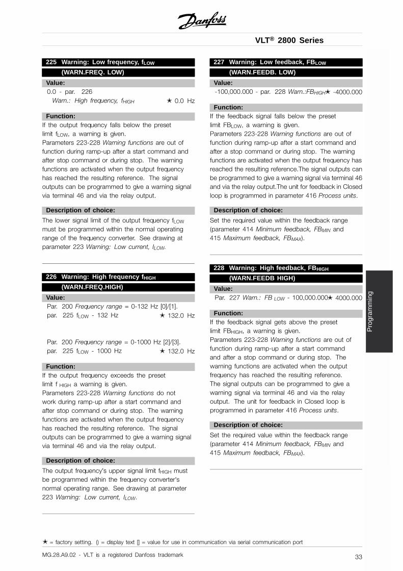
VLT® 2800 Series
Pro
gram
min
g
225 Warning: Low frequency, fLOW
(WARN.FREQ. LOW)
Value:0.0 - par. 226
Warn.: High frequency, fHIGH ✭ 0.0 Hz
Function:If the output frequency falls below the presetlimit fLOW, a warning is given.Parameters 223-228 Warning functions are out offunction during ramp-up after a start command andafter stop command or during stop. The warningfunctions are activated when the output frequencyhas reached the resulting reference. The signaloutputs can be programmed to give a warning signalvia terminal 46 and via the relay output.
Description of choice:
The lower signal limit of the output frequency fLOW
must be programmed within the normal operatingrange of the frequency converter. See drawing atparameter 223 Warning: Low current, ILOW.
226 Warning: High frequency fHIGH
(WARN.FREQ.HIGH)
Value:Par. 200 Frequency range = 0-132 Hz [0]/[1].par. 225 fLOW - 132 Hz ✭ 132.0 Hz
Par. 200 Frequency range = 0-1000 Hz [2]/[3].par. 225 fLOW - 1000 Hz ✭ 132.0 Hz
Function:If the output frequency exceeds the presetlimit f HIGH a warning is given.Parameters 223-228 Warning functions do notwork during ramp-up after a start command andafter stop command or during stop. The warningfunctions are activated when the output frequencyhas reached the resulting reference. The signaloutputs can be programmed to give a warning signalvia terminal 46 and via the relay output.
Description of choice:
The output frequency’s upper signal limit fHIGH mustbe programmed within the frequency converter’snormal operating range. See drawing at parameter223 Warning: Low current, ILOW.
227 Warning: Low feedback, FBLOW
(WARN.FEEDB. LOW)
Value:-100,000.000 - par. 228 Warn.:FBHIGH✭ -4000.000
Function:If the feedback signal falls below the presetlimit FBLOW, a warning is given.Parameters 223-228 Warning functions are out offunction during ramp-up after a start command andafter a stop command or during stop. The warningfunctions are activated when the output frequency hasreached the resulting reference.The signal outputs canbe programmed to give a warning signal via terminal 46and via the relay output.The unit for feedback in Closedloop is programmed in parameter 416 Process units.
Description of choice:
Set the required value within the feedback range(parameter 414 Minimum feedback, FBMIN and415 Maximum feedback, FBMAX).
228 Warning: High feedback, FBHIGH
(WARN.FEEDB HIGH)
Value:Par. 227 Warn.: FB LOW - 100,000.000✭ 4000.000
Function:If the feedback signal gets above the presetlimit FBHIGH, a warning is given.Parameters 223-228 Warning functions are out offunction during ramp-up after a start commandand after a stop command or during stop. Thewarning functions are activated when the outputfrequency has reached the resulting reference.The signal outputs can be programmed to give awarning signal via terminal 46 and via the relayoutput. The unit for feedback in Closed loop isprogrammed in parameter 416 Process units.
Description of choice:
Set the required value within the feedback range(parameter 414 Minimum feedback, FBMIN and415 Maximum feedback, FBMAX).
✭ = factory setting. () = display text [] = value for use in communication via serial communication port
MG.28.A9.02 - VLT is a registered Danfoss trademark 33
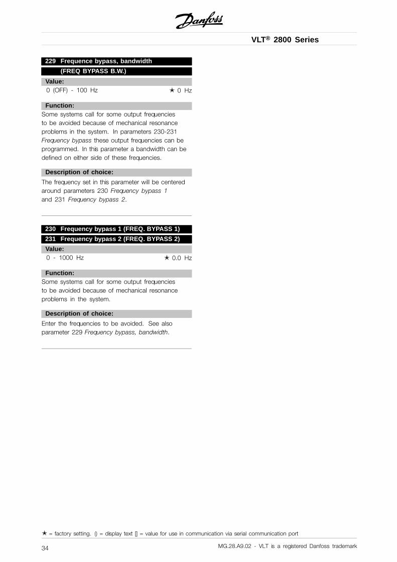
VLT® 2800 Series
229 Frequence bypass, bandwidth
(FREQ BYPASS B.W.)
Value:0 (OFF) - 100 Hz ✭ 0 Hz
Function:Some systems call for some output frequenciesto be avoided because of mechanical resonanceproblems in the system. In parameters 230-231Frequency bypass these output frequencies can beprogrammed. In this parameter a bandwidth can bedefined on either side of these frequencies.
Description of choice:
The frequency set in this parameter will be centeredaround parameters 230 Frequency bypass 1and 231 Frequency bypass 2.
230 Frequency bypass 1 (FREQ. BYPASS 1)
231 Frequency bypass 2 (FREQ. BYPASS 2)
Value:0 - 1000 Hz ✭ 0.0 Hz
Function:Some systems call for some output frequenciesto be avoided because of mechanical resonanceproblems in the system.
Description of choice:
Enter the frequencies to be avoided. See alsoparameter 229 Frequency bypass, bandwidth.
✭ = factory setting. () = display text [] = value for use in communication via serial communication port
MG.28.A9.02 - VLT is a registered Danfoss trademark34
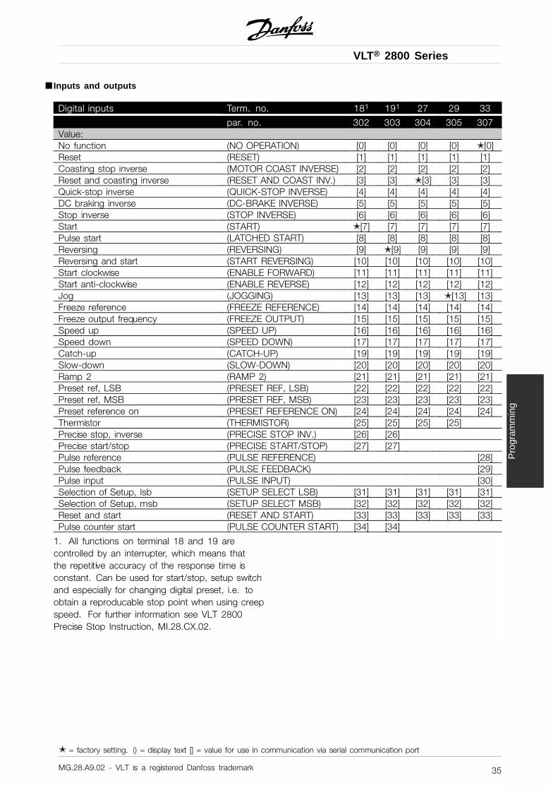
VLT® 2800 Series
Pro
gram
min
g
■ Inputs and outputs
Digital inputs Term. no. 181 191 27 29 33
par. no. 302 303 304 305 307Value:No function (NO OPERATION) [0] [0] [0] [0] ✭ [0]Reset (RESET) [1] [1] [1] [1] [1]Coasting stop inverse (MOTOR COAST INVERSE) [2] [2] [2] [2] [2]Reset and coasting inverse (RESET AND COAST INV.) [3] [3] ✭ [3] [3] [3]Quick-stop inverse (QUICK-STOP INVERSE) [4] [4] [4] [4] [4]DC braking inverse (DC-BRAKE INVERSE) [5] [5] [5] [5] [5]Stop inverse (STOP INVERSE) [6] [6] [6] [6] [6]Start (START) ✭ [7] [7] [7] [7] [7]Pulse start (LATCHED START) [8] [8] [8] [8] [8]Reversing (REVERSING) [9] ✭ [9] [9] [9] [9]Reversing and start (START REVERSING) [10] [10] [10] [10] [10]Start clockwise (ENABLE FORWARD) [11] [11] [11] [11] [11]Start anti-clockwise (ENABLE REVERSE) [12] [12] [12] [12] [12]Jog (JOGGING) [13] [13] [13] ✭ [13] [13]Freeze reference (FREEZE REFERENCE) [14] [14] [14] [14] [14]Freeze output frequency (FREEZE OUTPUT) [15] [15] [15] [15] [15]Speed up (SPEED UP) [16] [16] [16] [16] [16]Speed down (SPEED DOWN) [17] [17] [17] [17] [17]Catch-up (CATCH-UP) [19] [19] [19] [19] [19]Slow-down (SLOW-DOWN) [20] [20] [20] [20] [20]Ramp 2 (RAMP 2) [21] [21] [21] [21] [21]Preset ref, LSB (PRESET REF, LSB) [22] [22] [22] [22] [22]Preset ref, MSB (PRESET REF, MSB) [23] [23] [23] [23] [23]Preset reference on (PRESET REFERENCE ON) [24] [24] [24] [24] [24]Thermistor (THERMISTOR) [25] [25] [25] [25]Precise stop, inverse (PRECISE STOP INV.) [26] [26]Precise start/stop (PRECISE START/STOP) [27] [27]Pulse reference (PULSE REFERENCE) [28]Pulse feedback (PULSE FEEDBACK) [29]Pulse input (PULSE INPUT) [30]Selection of Setup, lsb (SETUP SELECT LSB) [31] [31] [31] [31] [31]Selection of Setup, msb (SETUP SELECT MSB) [32] [32] [32] [32] [32]Reset and start (RESET AND START) [33] [33] [33] [33] [33]Pulse counter start (PULSE COUNTER START) [34] [34]
1. All functions on terminal 18 and 19 arecontrolled by an interrupter, which means thatthe repetitive accuracy of the response time isconstant. Can be used for start/stop, setup switchand especially for changing digital preset, i.e. toobtain a reproducable stop point when using creepspeed. For further information see VLT 2800Precise Stop Instruction, MI.28.CX.02.
✭ = factory setting. () = display text [] = value for use in communication via serial communication port
MG.28.A9.02 - VLT is a registered Danfoss trademark 35
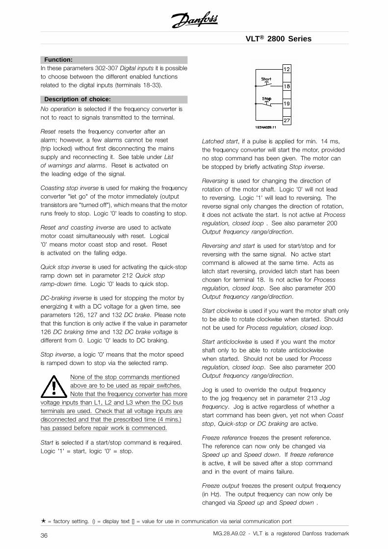
VLT® 2800 Series
Function:In these parameters 302-307 Digital inputs it is possibleto choose between the different enabled functionsrelated to the digital inputs (terminals 18-33).
Description of choice:
No operation is selected if the frequency converter isnot to react to signals transmitted to the terminal.
Reset resets the frequency converter after analarm; however, a few alarms cannot be reset(trip locked) without first disconnecting the mainssupply and reconnecting it. See table under Listof warnings and alarms. Reset is activated onthe leading edge of the signal.
Coasting stop inverse is used for making the frequencyconverter "let go" of the motor immediately (outputtransistors are "turned off"), which means that the motorruns freely to stop. Logic ’0’ leads to coasting to stop.
Reset and coasting inverse are used to activatemotor coast simultaneously with reset. Logical’0’ means motor coast stop and reset. Resetis activated on the falling edge.
Quick stop inverse is used for activating the quick-stopramp down set in parameter 212 Quick stopramp-down time. Logic ’0’ leads to quick stop.
DC-braking inverse is used for stopping the motor byenergizing it with a DC voltage for a given time, seeparameters 126, 127 and 132 DC brake. Please notethat this function is only active if the value in parameter126 DC braking time and 132 DC brake voltage isdifferent from 0. Logic ’0’ leads to DC braking.
Stop inverse, a logic ’0’ means that the motor speedis ramped down to stop via the selected ramp.
None of the stop commands mentionedabove are to be used as repair switches.Note that the frequency converter has more
voltage inputs than L1, L2 and L3 when the DC busterminals are used. Check that all voltage inputs aredisconnected and that the prescribed time (4 mins.)has passed before repair work is commenced.
Start is selected if a start/stop command is required.Logic ’1’ = start, logic ’0’ = stop.
Latched start, if a pulse is applied for min. 14 ms,the frequency converter will start the motor, providedno stop command has been given. The motor canbe stopped by briefly activating Stop inverse.
Reversing is used for changing the direction ofrotation of the motor shaft. Logic ’0’ will not leadto reversing. Logic ’1’ will lead to reversing. Thereverse signal only changes the direction of rotation,it does not activate the start. Is not active at Processregulation, closed loop . See also parameter 200Output frequency range/direction.
Reversing and start is used for start/stop and forreversing with the same signal. No active startcommand is allowed at the same time. Acts aslatch start reversing, provided latch start has beenchosen for terminal 18. Is not active for Processregulation, closed loop. See also parameter 200Output frequency range/direction.
Start clockwise is used if you want the motor shaft onlyto be able to rotate clockwise when started. Shouldnot be used for Process regulation, closed loop.
Start anticlockwise is used if you want the motorshaft only to be able to rotate anticlockwisewhen started. Should not be used for Processregulation, closed loop. See also parameter 200Output frequency range/direction.
Jog is used to override the output frequencyto the jog frequency set in parameter 213 Jogfrequency. Jog is active regardless of whether astart command has been given, yet not when Coaststop, Quick-stop or DC braking are active.
Freeze reference freezes the present reference.The reference can now only be changed viaSpeed up and Speed down. If freeze referenceis active, it will be saved after a stop commandand in the event of mains failure.
Freeze output freezes the present output frequency(in Hz). The output frequency can now only bechanged via Speed up and Speed down .
✭ = factory setting. () = display text [] = value for use in communication via serial communication port
MG.28.A9.02 - VLT is a registered Danfoss trademark36
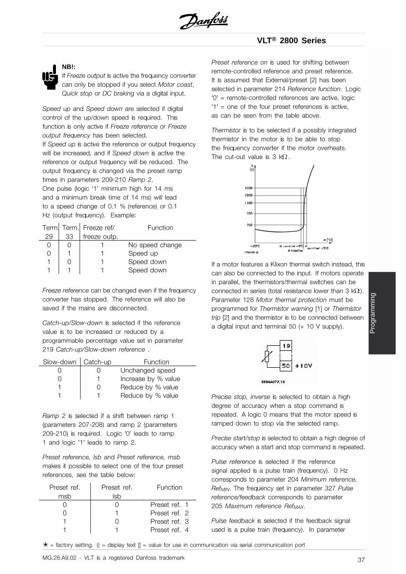
VLT® 2800 Series
Pro
gram
min
g
NB!:If Freeze output is active the frequency convertercan only be stopped if you select Motor coast,Quick stop or DC braking via a digital input.
Speed up and Speed down are selected if digitalcontrol of the up/down speed is required. Thisfunction is only active if Freeze reference or Freezeoutput frequency has been selected.If Speed up is active the reference or output frequencywill be increased, and if Speed down is active thereference or output frequency will be reduced. Theoutput frequency is changed via the preset ramptimes in parameters 209-210 Ramp 2.One pulse (logic ’1’ minimum high for 14 msand a minimum break time of 14 ms) will leadto a speed change of 0.1 % (reference) or 0.1Hz (output frequency). Example:
Term.29
Term.33
Freeze ref/freeze outp.
Function
0 0 1 No speed change0 1 1 Speed up1 0 1 Speed down1 1 1 Speed down
Freeze reference can be changed even if the frequencyconverter has stopped. The reference will also besaved if the mains are disconnected.
Catch-up/Slow-down is selected if the referencevalue is to be increased or reduced by aprogrammable percentage value set in parameter219 Catch-up/Slow-down reference .
Slow-down Catch-up Function0 0 Unchanged speed0 1 Increase by % value1 0 Reduce by % value1 1 Reduce by % value
Ramp 2 is selected if a shift between ramp 1(parameters 207-208) and ramp 2 (parameters209-210) is required. Logic ’0’ leads to ramp1 and logic ’1’ leads to ramp 2.
Preset reference, lsb and Preset reference, msbmakes it possible to select one of the four presetreferences, see the table below:
Preset ref.msb
Preset ref.lsb
Function
0 0 Preset ref. 10 1 Preset ref. 21 0 Preset ref. 31 1 Preset ref. 4
Preset reference on is used for shifting betweenremote-controlled reference and preset reference.It is assumed that External/preset [2] has beenselected in parameter 214 Reference function. Logic’0’ = remote-controlled references are active, logic’1’ = one of the four preset references is active,as can be seen from the table above.
Thermistor is to be selected if a possibly integratedthermistor in the motor is to be able to stopthe frequency converter if the motor overheats.The cut-out value is 3 k .
If a motor features a Klixon thermal switch instead, thiscan also be connected to the input. If motors operatein parallel, the thermistors/thermal switches can beconnected in series (total resistance lower than 3 k ).Parameter 128 Motor thermal protection must beprogrammed for Thermistor warning [1] or Thermistortrip [2] and the thermistor is to be connected betweena digital input and terminal 50 (+ 10 V supply).
Precise stop, inverse is selected to obtain a highdegree of accuracy when a stop command isrepeated. A logic 0 means that the motor speed isramped down to stop via the selected ramp.
Precise start/stop is selected to obtain a high degree ofaccuracy when a start and stop command is repeated.
Pulse reference is selected if the referencesignal applied is a pulse train (frequency). 0 Hzcorresponds to parameter 204 Minimum reference,RefMIN. The frequency set in parameter 327 Pulsereference/feedback corresponds to parameter205 Maximum reference RefMAX.
Pulse feedback is selected if the feedback signalused is a pulse train (frequency). In parameter
✭ = factory setting. () = display text [] = value for use in communication via serial communication port
MG.28.A9.02 - VLT is a registered Danfoss trademark 37
VLT® 2800 Series
327 Pulse reference/feedback the maximumpulse feedback frequency is set.
Pulse input is selected if a specific number of pulsesmust lead to a Precise stop, see parameter 343Precise stop and parameter 344 Counter value.
Selection of Setup, lsb and Selection of Setup,msb gives the possibility to select one of thefour setups. It is, however, a condition thatparameter 004 is set to Multisetup.
Reset and start can be used as a start function.If 24 V are connected to the digital input, this willcause the frequency converter to reset and the motorwill ramp up to the preset reference.
Pulse counter start is used to start a counterstop sequence with a pulse signal. The pulsewidth must at least be 14 ms and not longerthan the count period. See also parameter 343and the instruction, MI28CXYY.
308 Terminal 53, analogue input voltage
(AI [V]53FUNCT.)
Value:No function (NO OPERATION) [0]
✭ Reference (REFERENCE) [1]Feedback (FEEDBACK) [2]Wobble (WOBB.DELTA FREQ [%]) [10]
Function:In this parameter it is possible to select the functionrequired to be connected to terminal 53. Scaling of theinput signal is made in parameter 309 Terminal 53, min.scaling and parameter 310 Terminal 53, max. scaling.
Description of choice:
No function [0]. Is selected if the frequency converteris not to react to signals connected to the terminal.Reference [1]. If this function is selected, the referencecan be changed by means of an analogue referencesignal. If reference signals are connected to more thanone input, these reference signals must be added up.If a voltage feedback signal is connected, selectFeedback [2] on terminal 53.Wobble [10]The delta frequency can be controlled by the analoginput. If WOBB.DELTA FREQ is selected as analoginput (par. 308 or par. 314) the value selected inpar. 702 equals 100 % analog input.Example: Analog input = 4-20 mA, Delta freq. par.702 = 5 Hz → 4 mA = 0 Hz and 20 mA = 5 Hz.
If this function is chosen, see Wobble InstructionMI28JXYY for further information.
309 Terminal 53 Min. scaling
(AI 53 SCALE LOW)
Value:0.0 - 10.0 Volt ✭ 0.0 Volt
Function:This parameter is used for setting the signal valuethat is to correspond to the minimum reference orthe minimum feedback, parameter 204 Minimumreference, RefMIN / 414 Minimum feedback, FBMIN.
Description of choice:
Set the required voltage value. For reasons ofaccuracy, compensation should be made for voltageloss in long signal cables. If the Time out function is tobe used (parameter 317 Time out and 318 Functionafter time out), the value set must be higher than 1 Volt.
310 Terminal 53 Max. scaling
(AI 53 SCALE HIGH)
Value:0 - 10.0 Volt ✭ 10.0 Volt
Function:This parameter is used for setting the signal value thatis to correspond to the maximum reference valueor maximum feedback, parameter 205 Maximumreference, RefMAX / 414 Maximum feedback, FBMAX.
Description of choice:
Set the required voltage value. For reasons ofaccuracy, compensation should be made forvoltage losses in long signal cables.
314 Terminal 60, analogue input current
(AI [MA] 60 FUNCT)
Value:No function (NO OPERATION) [0]Reference (REFERENCE) [1]
✭ Feedback (FEEDBACK) [2]Wobble (WOBB.DELTA FREQ [%]) [10]
Function:This parameter allows a choice between the differentfunctions available for the input, terminal 60.Scaling of the input signal is effected in parameter
✭ = factory setting. () = display text [] = value for use in communication via serial communication port
MG.28.A9.02 - VLT is a registered Danfoss trademark38
VLT® 2800 Series
Pro
gram
min
g
315 Terminal 60, min. scaling and parameter316 Terminal 60, max. scaling.
Description of choice:
No function [0]. Is selected if the frequency converteris not to react to signals connected to the terminal.Reference [1]. If this function is selected, the referencecan be changed by means of an analogue referencesignal. If reference signals are connected to more thanone input, these reference signals must be added up.If one current feedback signal is connected,select Feedback [2] on terminal 60.Wobble [10]The delta frequency can be controlled by the analoginput. If WOBB.DELTA FREQ is selected as analoginput (par. 308 or par. 314) the value selected inpar. 702 equals 100 % analog input.Example: Analog input = 4-20 mA, Delta freq. par.702 = 5 Hz → 4 mA = 0 Hz and 20 mA = 5 Hz.If this function is chosen, see Wobble InstructionMI28JXYY for further information.
315 Terminal 60 Min. scaling
(AI 60 SCALE LOW)
Value:0.0 - 20.0 mA ✭ 4.0 mA
Function:In this parameter you can set the signal value that willcorrespond to the minimum reference or minimumfeedback, parameter 204 Minimum reference,RefMIN / 414 Minimum feedback, FBMIN.
Description of choice:
Set the required current value. If the Time outfunction is to be used (parameter 317 Timeout and 318 Function after time out ) the valueset must be higher than 2 mA.
316 Terminal 60 Max. scaling
(AI 60 SCALE HIGH)
Value:0.0 - 20.0 mA ✭ 20.0 mA
Function:This parameter is used for setting the signal value thatis to correspond to the maximum reference value,parameter 205 Maximum reference value, RefMAX.
Description of choice:
Set the required current value.
317 Time out(LIVE ZERO TIME O)
Value:1 - 99 sec. ✭ 10 sec.
Function:If the signal value of the reference or feedback signalconnected to one of the input terminals 53 or 60 fallsbelow 50 % of the minimum scaling for a period longerthan the time set, the function selected in parameter318 Function after time out will be activated. Thisfunction is only active if in parameter 309 Terminal53, min. scaling a value higher than 1 Volt has beenselected, or if in parameter 315 Terminal 60, min.scaling a value higher than 2 mA has been selected.
Description of choice:
Set the required time.
318 Function after time out(LIVE ZERO FUNCT.)
Value:✭ No operation (NO OPERATION) [0]
Freeze output frequency(FREEZE OUTPUT FREQ.) [1]Stop (STOP) [2]Jog (JOG) [3]Max. speed (MAX SPEED) [4]Stop and trip (STOP AND TRIP) [5]
Function:This parameter allows a choice of the function to beactivated after the expiry of the Time out (parameter317 Time out ). If a time-out function occurs at thesame time as a bus time-out function (parameter 513Bus time interval function ), the time-out functionin parameter 318 will be activated.
Description of choice:
The output frequency of the frequency converter can be:- frozen at the present frequency [1]- overruled to stop [2]- overruled to jog frequency [3]- overruled to max. output frequency [4]
✭ = factory setting. () = display text [] = value for use in communication via serial communication port
MG.28.A9.02 - VLT is a registered Danfoss trademark 39
VLT® 2800 Series
- overruled to stop with subsequent trip [5]
319 Analogue output terminal 42
(AO 42 FUNCTION)
Value:No function (NO OPERATION) [0]External reference min.-max. 0-20 mA(REF MIN-MAX = 0-20 MA) [1]External reference min.-max. 4-20 mA(REF MIN-MAX = 4-20 MA) [2]Feedback min.-max. 0-20 mA(FB MIN-MAX = 0-20 MA) [3]Feedback min.-max. 4-20 mA(FB MIN-MAX = 4-20 MA) [4]Output frequency 0-max 0-20 mA(0-FMAX = 0-20 MA) [5]Output frequency 0-max 4-20 mA(0-FMAX = 4-20 MA) [6]
✭ Output current 0-IINV 0-20 mA(0-IINV = 0-20 MA) [7]Output current 0-IIINV 4-20 mA(0-IINV = 4-20 MA) [8]Output power 0-PM,N 0-20 mA(0-PNOM = 0-20 MA) [9]Output power 0-PM,N 4-20 mA(0-PNOM = 4-20 MA) [10]Inverter temperature 20-100 °C 0-20 mA(TEMP 20-100 C=0-20 MA) [11]Inverter temperature 20-100 °C 4-20 mA(TEMP 20-100 C=4-20 MA) [12]
Function:The analogue output can be used for stating aprocess value. It is possible to choose two typesof output signals 0 - 20 mA or 4 - 20 mA.If used as a voltage output (0 - 10 V), a pull-downresistor of 500 must be fitted to common(terminal 55). If the output is used as a currentoutput the resulting resistance from the equipmentconnected may not exceed 500 .
Description of choice:
No function. Is selected if the analogueoutput is not to be used.
External RefMIN - RefMAX 0-20 mA/4-20 mA.An output signal is obtained, which is proportionalto the resulting reference value in the intervalMinimum reference, RefMIN - Maximum reference,RefMAX (parameters 204/205).
FBMIN-FBMAX 0-20 mA/ 4-20 mA.
An output signal is obtained, which is proportional to thefeedback value in the interval Minimum feedback, FBMIN
- Maximum feedback, FBMAX (parameter 414/415).
0-fMAX 0-20 mA/4-20 mA.An output signal is obtained, which is proportional tothe output frequency in the interval 0 - fMAX (parameter202 Output frequency, high limit, fMAX).
0 - IINV 0-20 mA/4-20 mA.An output signal is obtained, which is proportionalto the output current in the interval 0 - IINV
0 - PM,N 0-20 mA/4-20 mA.An output signal is obtained, which is proportional tothe present output power. 20 mA corresponds to thevalue set in parameter 102 Motor power, PM,N.
✭ = factory setting. () = display text [] = value for use in communication via serial communication port
MG.28.A9.02 - VLT is a registered Danfoss trademark40
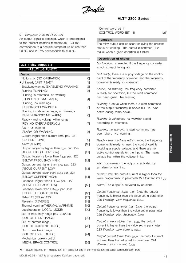
VLT® 2800 Series
Pro
gram
min
g
0 - Temp.MAX 0-20 mA/4-20 mA.An output signal is obtained, which is proportionalto the present heatsink temperature. 0/4 mAcorresponds to a heatsink temperature of less than20 °C, and 20 mA corresponds to 100 °C.
323 Relay output 1-3
(RELAY 1-3 FUNCT.)
Value:No function (NO OPERATION) [0]
✭ Unit ready (UNIT READY) [1]Enable/no warning (ENABLE/NO WARNING) [2]Running (RUNNING) [3]Running in reference, no warning( RUN ON REF/NO WARN) [4]Running, no warnings(RUNNING/NO WARNING) [5]Running in reference range, no warnings(RUN IN RANGE/ NO WARN) [6]Ready - mains voltage within range(RDY NO OVER/UNDERVOL) [7]Alarm or warning(ALARM OR WARNING) [8]Current higher than current limit, par. 221(CURRENT LIMIT) [9]Alarm (ALARM) [10]Output frequency higher than fLOW par. 225(ABOVE FREQUENCY LOW) [11]Output frequency lower than fHIGH par. 226(BELOW FREQUENCY HIGH) [12]Output current higher than ILOW par. 223(ABOVE CURRENT LOW) [13]Output current lower than IHIGH par. 224(BELOW CURRENT HIGH) [14]Feedback higher than FBLOW par. 227(ABOVE FEEDBACK LOW) [15]Feedback lower than FBHIGH par. 228(UNDER FEEDBACK HIGH) [16]Relay 123 (RELAY 123) [17]Reversing (REVERSE) [18]Thermal warning (THERMAL WARNING) [19]Local operation (LOCAL MODE) [20]Out of frequency range par. 225/226(OUT OF FREQ RANGE) [22]Out of current range(OUT OF CURRENT RANGE) [23]Out of feedback range(OUT OF FDBK. RANGE) [24]Mechanical brake control(MECH. BRAKE CONTROL) [25]
Control word bit 11(CONTROL WORD BIT 11) [26]
Function:The relay output can be used for giving the presentstatus or warning. The output is activated (1-2make) when a given condition is fulfilled.
Description of choice:
No function. Is selected if the frequency converteris not to react to signals.
Unit ready, there is a supply voltage on the controlcard of the frequency converter, and the frequencyconverter is ready for operation.
Enable, no warning, the frequency converteris ready for operation, but no start commandhas been given. No warning.
Running is active when there is a start commandor the output frequency is above 0.1 Hz. Alsoactive during ramp-down.
Running in reference, no warning speedaccording to reference.
Running, no warning, a start command hasbeen given. No warning.
Ready - mains voltage within range, the frequencyconverter is ready for use; the control card isreceiving a supply voltage; and there are noactive control signals on the inputs. The mainsvoltage lies within the voltage limits.
Alarm or warning, the output is activated byan alarm or warning.
Current limit, the output current is higher than thevalue programmed in parameter 221 Current limit I LIM.
Alarm, The output is activated by an alarm.
Output frequency higher than fLOW, the outputfrequency is higher than the value set in parameter225 Warning: Low frequency, fLOW.
Output frequency lower than fHIGH, the outputfrequency is lower than the value set in parameter226 Warning: High frequency, fHIGH.
Output current higher than ILOW, the outputcurrent is higher than the value set in parameter223 Warning: Low current, ILOW.
Output current lower than IHIGH, the output currentis lower than the value set in parameter 224Warning: High current, IHIGH.
✭ = factory setting. () = display text [] = value for use in communication via serial communication port
MG.28.A9.02 - VLT is a registered Danfoss trademark 41
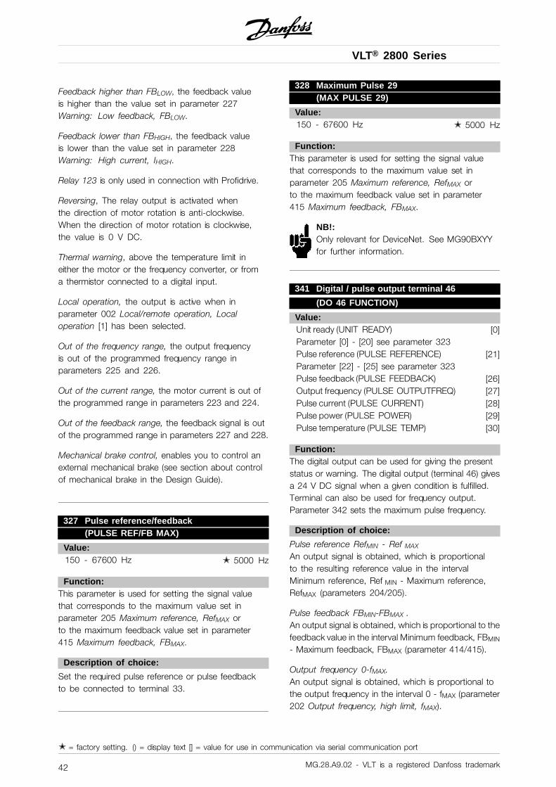
VLT® 2800 Series
Feedback higher than FBLOW, the feedback valueis higher than the value set in parameter 227Warning: Low feedback, FBLOW.
Feedback lower than FBHIGH, the feedback valueis lower than the value set in parameter 228Warning: High current, IHIGH.
Relay 123 is only used in connection with Profidrive.
Reversing, The relay output is activated whenthe direction of motor rotation is anti-clockwise.When the direction of motor rotation is clockwise,the value is 0 V DC.
Thermal warning, above the temperature limit ineither the motor or the frequency converter, or froma thermistor connected to a digital input.
Local operation, the output is active when inparameter 002 Local/remote operation, Localoperation [1] has been selected.
Out of the frequency range, the output frequencyis out of the programmed frequency range inparameters 225 and 226.
Out of the current range, the motor current is out ofthe programmed range in parameters 223 and 224.
Out of the feedback range, the feedback signal is outof the programmed range in parameters 227 and 228.
Mechanical brake control, enables you to control anexternal mechanical brake (see section about controlof mechanical brake in the Design Guide).
327 Pulse reference/feedback(PULSE REF/FB MAX)
Value:150 - 67600 Hz ✭ 5000 Hz
Function:This parameter is used for setting the signal valuethat corresponds to the maximum value set inparameter 205 Maximum reference, RefMAX orto the maximum feedback value set in parameter415 Maximum feedback, FBMAX.
Description of choice:
Set the required pulse reference or pulse feedbackto be connected to terminal 33.
328 Maximum Pulse 29(MAX PULSE 29)
Value:150 - 67600 Hz ✭ 5000 Hz
Function:This parameter is used for setting the signal valuethat corresponds to the maximum value set inparameter 205 Maximum reference, RefMAX orto the maximum feedback value set in parameter415 Maximum feedback, FBMAX.
NB!:Only relevant for DeviceNet. See MG90BXYYfor further information.
341 Digital / pulse output terminal 46
(DO 46 FUNCTION)
Value:Unit ready (UNIT READY) [0]Parameter [0] - [20] see parameter 323Pulse reference (PULSE REFERENCE) [21]Parameter [22] - [25] see parameter 323Pulse feedback (PULSE FEEDBACK) [26]Output frequency (PULSE OUTPUTFREQ) [27]Pulse current (PULSE CURRENT) [28]Pulse power (PULSE POWER) [29]Pulse temperature (PULSE TEMP) [30]
Function:The digital output can be used for giving the presentstatus or warning. The digital output (terminal 46) givesa 24 V DC signal when a given condition is fulfilled.Terminal can also be used for frequency output.Parameter 342 sets the maximum pulse frequency.
Description of choice:
Pulse reference RefMIN - Ref MAX
An output signal is obtained, which is proportionalto the resulting reference value in the intervalMinimum reference, Ref MIN - Maximum reference,RefMAX (parameters 204/205).
Pulse feedback FBMIN-FBMAX .An output signal is obtained, which is proportional to thefeedback value in the interval Minimum feedback, FBMIN
- Maximum feedback, FBMAX (parameter 414/415).
Output frequency 0-fMAX.An output signal is obtained, which is proportional tothe output frequency in the interval 0 - fMAX (parameter202 Output frequency, high limit, fMAX).
✭ = factory setting. () = display text [] = value for use in communication via serial communication port
MG.28.A9.02 - VLT is a registered Danfoss trademark42
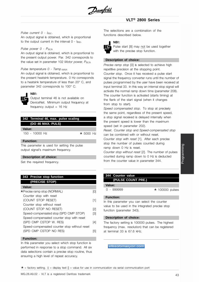
VLT® 2800 Series
Pro
gram
min
g
Pulse current 0 - IINV..An output signal is obtained, which is proportionalto the output current in the interval 0 - IINV.
Pulse power 0 - PM,N.An output signal is obtained, which is proportional tothe present output power. Par. 342 corresponds tothe value set in parameter 102 Motor power, PM,N.
Pulse temperature 0 - Temp.MAX.An output signal is obtained, which is proportional tothe present heatsink temperature. 0 Hz correspondsto a heatsink temperature of less than 20° C, andparameter 342 corresponds to 100° C.
NB!:Output terminal 46 is not available onDeviceNet. Minimum output frequency atfrequency output = 16 Hz
342 Terminal 46, max. pulse scaling
(DO 46 MAX. PULS)
Value:150 - 10000 Hz ✭ 5000 Hz
Function:This parameter is used for setting the pulseoutput signal’s maximum frequency.
Description of choice:
Set the required frequency.
343 Precise stop function
(PRECISE STOP)
Value:✭ Precise ramp stop (NORMAL) [0]
Counter stop with reset(COUNT STOP RESET) [1]Counter stop without reset(COUNT STOP NO RESET) [2]Speed-compensated stop (SPD CMP STOP) [3]Speed-compensated counter stop with reset(SPD CMP CSTOP W. RES) [4]Speed-compensated counter stop without reset(SPD CMP CSTOP NO RES) [5]
Function:In this parameter you select which stop function isperformed in response to a stop command. All sixdata selections contain a precise stop routine, thusensuring a high level of repeat accuracy.
The selections are a combination of thefunctions described below.
NB!:Pulse start [8] may not be used togetherwith the precise stop function.
Description of choice:
Precise ramp stop [0] is selected to achieve highrepetitive precision at the stopping point.Counter stop. Once it has received a pulse startsignal the frequency converter runs until the number ofpulses programmed by the user have been received atinput terminal 33. In this way an internal stop signal willactivate the normal ramp down time (parameter 208).The counter function is activated (starts timing) atthe flank of the start signal (when it changesfrom stop to start).Speed compensated stop. To stop at preciselythe same point, regardless of the present speed,a stop signal received is delayed internally whenthe present speed is lower than the maximumspeed (set in parameter 202).Reset. Counter stop and Speed-compensated stopcan be combined with or without reset.Counter stop with reset [1]. After each precisestop the number of pulses counted duringramp down 0 Hz is reset.Counter stop without reset [2]. The number of pulsescounted during ramp down to 0 Hz is deductedfrom the counter value in parameter 344.
344 Counter value(PULSE COUNT PRE.)
Value:0 - 999999 ✭ 100000 pulses
Function:In this parameter you can select the countervalue to be used in the integrated precise stopfunction (parameter 343).
Description of choice:
The factory setting is 100000 pulses. The highestfrequency (max. resolution) that can be registeredat terminal 33 is 67.6 kHz.
✭ = factory setting. () = display text [] = value for use in communication via serial communication port
MG.28.A9.02 - VLT is a registered Danfoss trademark 43
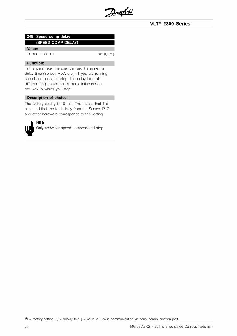
VLT® 2800 Series
349 Speed comp delay
(SPEED COMP DELAY)
Value:0 ms - 100 ms ✭ 10 ms
Function:In this parameter the user can set the system’sdelay time (Sensor, PLC, etc.). If you are runningspeed-compensated stop, the delay time atdifferent frequencies has a major influence onthe way in which you stop.
Description of choice:
The factory setting is 10 ms. This means that it isassumed that the total delay from the Sensor, PLCand other hardware corresponds to this setting.
NB!:Only active for speed-compensated stop.
✭ = factory setting. () = display text [] = value for use in communication via serial communication port
MG.28.A9.02 - VLT is a registered Danfoss trademark44
VLT® 2800 Series
Pro
gram
min
g
■ Special functions
400 Brake function(BRAKE FUNCTION)
Value:Off (OFF) [0]Resistor brake(RESISTOR) [1]AC brake (AC BRAKE) [4]Load sharing (LOAD SHARING) [5]
Factory setting depends on unit type.
Function:Resistor brake [1] is selected if the frequency converterhas an integral brake transistor and brake resistor isconnected to terminals 81, 82. A higher intermediatecircuit voltage is permitted during braking (generatedoperation) when a brake resistor is connected.AC brake [4] can be selected to improve brakingwithout using brake resistors. Please note that ACbrake [4] is not as effective as Resistor brake [1].
Description of choice:
Select Resistor brake [1] if a brake resistor is connected.Select AC brake [4] if short-term generated loads occur.See parameter 144 Gain AC brake to set the brake.
Select Load sharing [5] if this is used.
NB!:A change of selection will not becomeactive until the mains voltage has beendisconnected and reconnected.
405 Reset function(RESET MODE)
Value:✭ Manual reset (MANUAL RESET) [0]
Automatic reset x 1(AUTOMATIC X 1) [1]Automatic reset x 3(AUTOMATIC X 3) [3]Automatic reset x 10(AUTOMATIC X 10) [10]Reset at power-up(RESET AT POWER UP) [11]
Function:This parameter makes it possible to select whetherreset and restart after a trip are to be manual orwhether the frequency converter is to be reset andrestarted automatically. Furthermore, it is possibleto select the number of times a restart is to be
attempted. The time between each attempt is setin parameter 406 Automatic restart time.
Description of choice:
If Manual reset [0] is selected, reset is to be carriedout via the [STOP/RESET] key, a digital input orserial communication. If the frequency converteris to carry out an automatic reset and restart aftera trip, select data value [1], [3] or [10].If Reset at power-up [11] is selected, the frequencyconverter will carry out a reset if there has been afault in connection with the mains failure.
The motor may start without warning.
406 Automatic restart time(AUTORESTART TIME)
Value:0 - 10 sec. ✭ 5 sec.
Function:This parameter allows setting of the time fromtripping until the automatic reset function begins. Itis assumed that automatic reset has been selectedin parameter 405 Reset function.
Description of choice:
Set the required time.
409 Trip delay overcurrent, ILIM
(TRIP DELAY CUR.)
Value:0 - 60 sec. (61=OFF) ✭ OFF
Function:When the frequency converter registers that theoutput current has reached the current limit ILIM
(parameter 221 Current limit) and remains therefor the preset time, it is disconnected. Can beused to protect the application, like the ETRwill protect the motor if selected.
Description of choice:
Select how long the frequency converter shouldmaintain the output current at the current limitILIM before it disconnects. At OFF parameter 409Trip delay overcurrent, ILIM is not working, i.e.disconnection will not take place.
✭ = factory setting. () = display text [] = value for use in communication via serial communication port
MG.28.A9.02 - VLT is a registered Danfoss trademark 45
VLT® 2800 Series
411 Switching frequency
(SWITCH FREQ.)
Value:3000 - 14000 Hz (VLT 2803 - 2875) ✭ 4500 Hz3000 - 10000 Hz (VLT 2880 - 2882) ✭ 4500 Hz
Function:The set value determines the switching frequency of theinverter. If the switching frequency is changed, this mayhelp to minimise possible acoustic noise from the motor.
NB!:The output frequency of the frequency convertercan never assume a value higher than 1/10of the switching frequency.
Description of choice:
When the motor is running, the switching frequencyis adjusted in parameter 411 Switching frequencyuntil the frequency has been obtained at whichthe motor is as low-noise as possible.
NB!:The switching frequency is reducedautomatically as a function of the load.See Temperature-Dependent Switching
Frequency under Special Conditions .When LC-filter connected is selected in parameter412, the minimum switching frequency is 4.5 kHz.
412 Variable switching frequency
(VAR CARRIER FREQ.)
Value:✭ Without LC-filter (WITHOUT LC-FILTER) [2]
LC-filter connected(LC-FILTER CONNECTED) [3]
Function:The parameter must be set to LC-filter connectedif an LC-filter is connected between the frequencyconverter and the motor.
Description of choice:
The LC-filter connected [3] must be used if anLC-filter is connected between the frequencyconverter and the motor, as otherwise the frequencyconverter cannot protect the LC-filter.
NB!:When the LC filter is selected the switchingfrequency is changed to 4.5 kHz.
413 Overmodulation function(OVERMODULATION)
Value:Off (OFF) [0]
✭ On (ON) [1]
Function:This parameter allows connection of theovermodulation function for the output voltage.
Description of choice:
Off [0] means that there is no overmodulationof the output voltage, which means that torqueripple on the motor shaft is avoided. This canbe a good feature, e.g. on grinding machines.On [1] means that an output voltage can be obtainedwhich is greater than the mains voltage (up to 5 %).
414 Minimum feedback, FB MIN
(MIN. FEEDBACK)
Value:-100,000.000 - par. 415 FBMAX ✭ 0.000
Function:Parameter 414 Minimum feedback, FBMIN and 415Maximum feedback, FB MAX are used to scale thedisplay text to make it show the feedback signal in aprocess unit proportionally to the signal on the input.
Description of choice:
Set the value to be shown on the display as theminimum feedback signal value on the selectedfeedback input (parameters 308/314 Analogue inputs).
415 Maximum feedback, FBMAX
(MAX. FEEDBACK)
Value:FBMIN - 100,000.000 ✭ 1500.000
Function:See description of parameter 414 Minimumfeedback, FBMIN.
Description of choice:
Set the value to be shown on the display when themaximum feedback has been obtained on the selectedfeedback input (parameter 308/314 Analogue inputs).
✭ = factory setting. () = display text [] = value for use in communication via serial communication port
MG.28.A9.02 - VLT is a registered Danfoss trademark46
VLT® 2800 Series
Pro
gram
min
g
416 Process units(REF/FEEDB. UNIT)
Value:✭ No unit (NO UNIT) [0]
% (%) [1]ppm (PPM) [2]rpm (RPM) [3]bar (BAR) [4]Cycles/min (CYCLE/MI) [5]Pulses/s (PULSE/S) [6]Units/s (UNITS/S) [7]Units/min. (UNITS/MI) [8]Units/h (UNITS/H) [9]°C (°C) [10]Pa (PA) [11]l/s (L/S) [12]m3/s (M3/S) [13]l/min. (L/M) [14]m3/min. (M3/MIN) [15]l/h (L/H) [16]m3/h (M3/H) [17]Kg/s (KG/S) [18]Kg/min. (KG/MIN) [19]Kg/hour (KG/H) [20]Tons/min. (T/MIN) [21]Tons/hour (T/H) [22]Metres (M) [23]Nm (NM) [24]m/s (M/S) [25]m/min. (M/MIN) [26]°F (°F) [27]In wg (IN WG) [28]gal/s (GAL/S) [29]Ft3/s (FT3/S) [30]Gal/min. (GAL/MIN) [31]Ft3/min. (FT3/MIN) [32]Gal/h (GAL/H) [33]Ft3/h (FT3/H) [34]Lb/s (LB/S) [35]Lb/min. (LB/MIN) [36]Lb/hour (LB/H) [37]Lb ft (LB FT) [38]Ft/s (FT/S) [39]Ft/min. (FT/MIN) [40]
Function:Select among different units to be shown on thedisplay. The unit is read out if an LCP controlunit can be connected, and if Reference [unit] [2]or Feedback [unit] [3] has been selected in oneof parameters 009-012 Display read-out, and inDisplay mode. The unit is used in Closed loop
also as a unit for Minimum/Maximum referenceand Minimum/Maximum feedback.
Description of choice:
Select the required unit for the reference/feed-back signal.
NB!:Parameters 417-421 are only used, if inparameter 100 Configuration the selectionmade is Speed regulation, closed loop [1].
417 Speed PID proportional gain
(SPEED PROP GAIN)
Value:0.000 (OFF) - 1.000 ✭ 0.010
Function:Proportional gain indicates how many times thefault (deviation between the feedback signal andthe setpoint) is to be amplified.
Description of choice:
Quick regulation is obtained at high amplification,but if the amplification is too high, the process maybecome unstable in the case of overshooting.
418 Speed PID integral time
(SPEED INT. TIME)
Value:20.00 - 999.99 ms (1000 = OFF) ✭ 100 ms
Function:The integral time determines how long the PIDregulator takes to correct the error. The greaterthe error, the quicker the integrator frequencycontribution will increase. The integral time is thetime the integrator needs to achieve the samechange as the proportional amplification.
Description of choice:
Quick regulation is obtained through a short integraltime. However, if this time is too short, it can makethe process unstable. If the integral time is long,major deviations from the required reference mayoccur, since the process regulator will take longto regulate if an error has occurred.
✭ = factory setting. () = display text [] = value for use in communication via serial communication port
MG.28.A9.02 - VLT is a registered Danfoss trademark 47
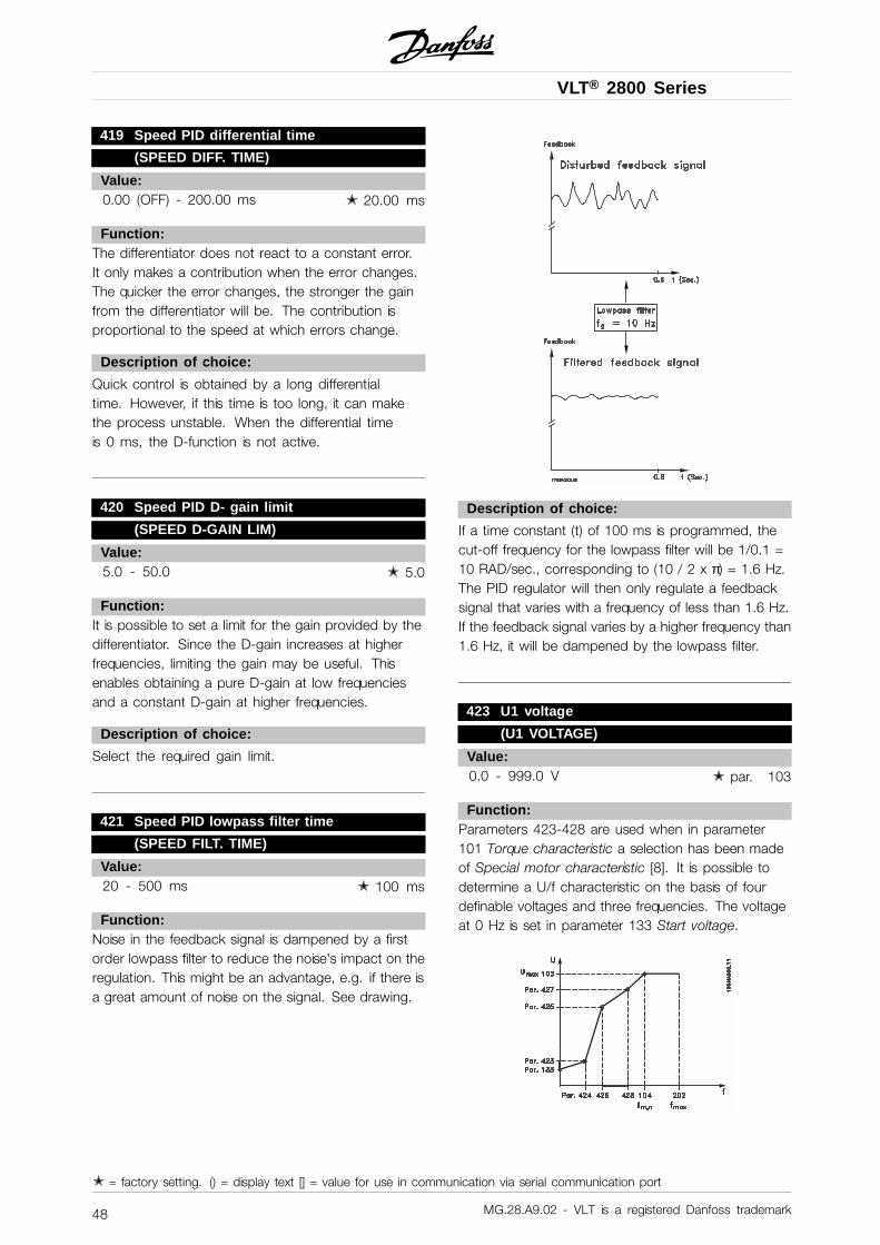
VLT® 2800 Series
419 Speed PID differential time
(SPEED DIFF. TIME)
Value:0.00 (OFF) - 200.00 ms ✭ 20.00 ms
Function:The differentiator does not react to a constant error.It only makes a contribution when the error changes.The quicker the error changes, the stronger the gainfrom the differentiator will be. The contribution isproportional to the speed at which errors change.
Description of choice:
Quick control is obtained by a long differentialtime. However, if this time is too long, it can makethe process unstable. When the differential timeis 0 ms, the D-function is not active.
420 Speed PID D- gain limit
(SPEED D-GAIN LIM)
Value:5.0 - 50.0 ✭ 5.0
Function:It is possible to set a limit for the gain provided by thedifferentiator. Since the D-gain increases at higherfrequencies, limiting the gain may be useful. Thisenables obtaining a pure D-gain at low frequenciesand a constant D-gain at higher frequencies.
Description of choice:
Select the required gain limit.
421 Speed PID lowpass filter time
(SPEED FILT. TIME)
Value:20 - 500 ms ✭ 100 ms
Function:Noise in the feedback signal is dampened by a firstorder lowpass filter to reduce the noise’s impact on theregulation. This might be an advantage, e.g. if there isa great amount of noise on the signal. See drawing.
Description of choice:
If a time constant (t) of 100 ms is programmed, thecut-off frequency for the lowpass filter will be 1/0.1 =10 RAD/sec., corresponding to (10 / 2 x π) = 1.6 Hz.The PID regulator will then only regulate a feedbacksignal that varies with a frequency of less than 1.6 Hz.If the feedback signal varies by a higher frequency than1.6 Hz, it will be dampened by the lowpass filter.
423 U1 voltage
(U1 VOLTAGE)
Value:0.0 - 999.0 V ✭ par. 103
Function:Parameters 423-428 are used when in parameter101 Torque characteristic a selection has been madeof Special motor characteristic [8]. It is possible todetermine a U/f characteristic on the basis of fourdefinable voltages and three frequencies. The voltageat 0 Hz is set in parameter 133 Start voltage.
✭ = factory setting. () = display text [] = value for use in communication via serial communication port
MG.28.A9.02 - VLT is a registered Danfoss trademark48
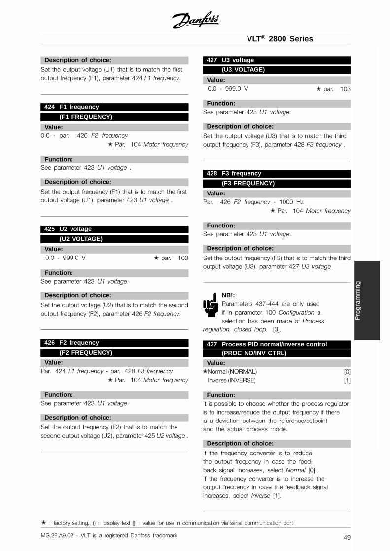
VLT® 2800 Series
Pro
gram
min
g
Description of choice:
Set the output voltage (U1) that is to match the firstoutput frequency (F1), parameter 424 F1 frequency.
424 F1 frequency
(F1 FREQUENCY)
Value:0.0 - par. 426 F2 frequency
✭ Par. 104 Motor frequency
Function:See parameter 423 U1 voltage .
Description of choice:
Set the output frequency (F1) that is to match the firstoutput voltage (U1), parameter 423 U1 voltage .
425 U2 voltage
(U2 VOLTAGE)
Value:0.0 - 999.0 V ✭ par. 103
Function:See parameter 423 U1 voltage.
Description of choice:
Set the output voltage (U2) that is to match the secondoutput frequency (F2), parameter 426 F2 frequency.
426 F2 frequency
(F2 FREQUENCY)
Value:Par. 424 F1 frequency - par. 428 F3 frequency
✭ Par. 104 Motor frequency
Function:See parameter 423 U1 voltage.
Description of choice:
Set the output frequency (F2) that is to match thesecond output voltage (U2), parameter 425 U2 voltage .
427 U3 voltage
(U3 VOLTAGE)
Value:0.0 - 999.0 V ✭ par. 103
Function:See parameter 423 U1 voltage.
Description of choice:
Set the output voltage (U3) that is to match the thirdoutput frequency (F3), parameter 428 F3 frequency .
428 F3 frequency
(F3 FREQUENCY)
Value:Par. 426 F2 frequency - 1000 Hz
✭ Par. 104 Motor frequency
Function:See parameter 423 U1 voltage.
Description of choice:
Set the output frequency (F3) that is to match the thirdoutput voltage (U3), parameter 427 U3 voltage .
NB!:Parameters 437-444 are only usedif in parameter 100 Configuration aselection has been made of Process
regulation, closed loop. [3].
437 Process PID normal/inverse control(PROC NO/INV CTRL)
Value:✭ Normal (NORMAL) [0]
Inverse (INVERSE) [1]
Function:It is possible to choose whether the process regulatoris to increase/reduce the output frequency if thereis a deviation between the reference/setpointand the actual process mode.
Description of choice:
If the frequency converter is to reducethe output frequency in case the feed-back signal increases, select Normal [0].If the frequency converter is to increase theoutput frequency in case the feedback signalincreases, select Inverse [1].
✭ = factory setting. () = display text [] = value for use in communication via serial communication port
MG.28.A9.02 - VLT is a registered Danfoss trademark 49
VLT® 2800 Series
438 Proces PID anti windup
(PROC ANTI WINDUP)
Value:Not active (DISABLE) [0]
✭ Active (ENABLE) [1]
Function:It is possible to select whether the process regulator isto continue regulating on a deviation even if it is notpossible to increase/reduce the output frequency.
Description of choice:
The factory setting is Enable [1], which means thatthe integration link is initialised in relation to theactual output frequency if either the current limit, thevoltage limit or the max./min. frequency has beenreached. The process regulator will not engageagain until either the error is zero or its sign haschanged. Select Disable [0] if the integrator is tocontinue integrating on the deviation, even if it is notpossible to remove the fault by such control.
NB!:If Disable [0] is selected, it will mean that whenthe deviation changes its sign, the integratorwill first have to integrate down from the
level obtained as a result of the former error, beforeany change in output frequency occurs.
439 Process PID start frequency
(PROC START VALUE)
Value:fMIN - fMAX (parameter 201/202)
✭ Par. 201 Output frequency, low limit, fMIN
Function:When the start signal comes, the frequency converterwill react in the form of Open loop and will notchange to Closed loop until the programmed startfrequency is reached. This makes it possible to set afrequency that corresponds to the speed at which theprocess normally runs, which will enable the requiredprocess conditions to be reached sooner.
Description of choice:
Set the required start frequency.
NB!:If the frequency converter is running a thecurrent limit before the required start frequencyis obtained, the process regulator will not be
activated. For the regulator to be activated anyway, thestart frequency must be lower to the required outputfrequency. This can be done during operation.
440 Proces PID proportioanl gain
(PROC. PROP. GAIN)
Value:0.0 - 10.00 ✭ 0.01
Function:The proportional gain indicates the number oftimes the deviation between the setpoint and thefeedback signal is to be applied.
Description of choice:
Quick regulation is obtained by a high gain, butif the gain is too high, the process may becomeunstable due to overshoot.
441 Process PID integration time
(PROC. INTEGR. T.)
Value:0.01 - 9999.99 (OFF) ✭ OFF
Function:The integrator provides an increasing gain at aconstant error between the reference/setpoint and thefeedback signal. The greater the error, the quickerthe integrator frequency contribution will increase.Theintegral time is the time needed by the integrator tomake the same change as the proportional gain.
Description of choice:
Quick regulation is obtained at a short integral time.However, this time may become too short, which canmake the process unstable due to overswing. If theintegral time is long, major deviations from the requiredsetpoint may occur, since the process regulator willtake a long time to regulate in relation to a given error.
✭ = factory setting. () = display text [] = value for use in communication via serial communication port
MG.28.A9.02 - VLT is a registered Danfoss trademark50
VLT® 2800 Series
Pro
gram
min
g
442 Process PID differentiation time(PROC. DIFF. TIME)
Value:0.00 (OFF) - 10.00 sec. ✭ 0.00 sec.
Function:The differentiator does not react to a constant error.It only makes a gain when an error changes. Thequicker the deviation changes, the stronger the gainfrom the differentiator. The gain is proportional tothe speed at which the deviation changes.
Description of choice:
Quick regulation is obtained with a long differentiationtime. However, this time may become too long, whichcan make the process unstable due to overswing.
443 Process PID diff. gain limit
(PROC. DIFF.GAIN)
Value:5.0 - 50.0 ✭ 5.0
Function:It is possible to set a limit for the differentiator gain.The differentiator gain will increase if there are fastchanges, which is why it can be beneficial to limit thisgain. Thereby a pure differentiator gain is obtainedat slow changes and a constant differentiator gainwhere quick changes to the deviation occur.
Description of choice:
Select a differentiator gain limit as required.
444 Process PID lowpass filter time
(PROC FILTER TIME)
Value:0.02 - 10.00 ✭ 0.02
Function:Noise in the feedback signal is dampened by a firstorder lowpass filter to reduce the noise’s impact onthe process regulation. This can be an advantagee.g. if there is a lot of noise on the signal.
Description of choice:
Select the required time constant (t). If a time constant(t) of 0.1 s is programmed, the cut-off frequencyfor the lowpass filter will be 1/0.1 = 10 RAD/sec.,corresponding to (10 / 2 x π) = 1.6 Hz. The processregulator will thus only regulate a feedback signalthat varies by a frequency lower than 1.6 Hz. If the
feedback signal varies by a higher frequency than 1.6Hz, it will be dampened by the lowpass filter.
445 Flying start
(FLYINGSTART)
Value:✭ Off (DISABLE) [0]
OK - same direction(OK-SAME DIRECTION) [1]OK - both directions(OK-BOTH DIRECTIONS) [2]DC brake and start(DC-BRAKE BEF. START) [3]
Function:This function makes it possible to ’catch’ a rotatingmotor shaft, which is no longer controlled by thefrequency converter, e.g. because of a mainsdrop-out. The function is activated each time a startcommand is enabled. For the frequency converterto be able to ’catch’ the rotating motor shaft, themotor speed must be lower than the frequencythat corresponds to the frequency in parameter202 Output frequency, high limit, f MAX.
Description of choice:
Select Disable [0] if this function is not required.
Select OK - same direction [1] if the motor shaftis only able to rotate in the same direction whencutting in. OK - same direction [1] should beselected if in parameter 200 Output frequency rangea selection has been of Clockwise only .
Select OK - both directions [2] if the motor is ableto rotate in both directions when cutting in.
Select DC brake and start [3] if the frequency converteris to be able to brake the motor using the DC brakefirst, followed by start. It is assumed that parameters126-127/132 DC brake are enabled. In the caseof higher ’Windmilling’ (rotating motor) effects, thefrequency converter is not able to ’catch’ a rotatingmotor without selecting DC brake and start .
Limitations:- Too low inertia will lead to load acceleration, which
can be dangerous or prevent correct catching of arotating motor. Use the DC brake instead.
- If the load is driven, e.g. by ’Windmilling’(rotating motor) effects, the unit may cutout because of overvoltage.
✭ = factory setting. () = display text [] = value for use in communication via serial communication port
MG.28.A9.02 - VLT is a registered Danfoss trademark 51

VLT® 2800 Series
- Flying start does not work at lower valuesthan 250 rpm.
451 Speed PID feedforward factor
(FEEDFORWARD FACT)
Value:0 - 500 % ✭ 100 %
Function:This parameter is only active if in parameter 100Configuration the selection made is Speed regulation,closed loop. The FF function sends a larger or smallerpart of the reference signal outside the PID controllerin such a way that the PID controller only has aninfluence on part of the control signal. Any changeto the set point will thus have a direct effect on themotor speed. The FF factor provides high dynamismwhen changing the set point and less overswing.
Description of choice:
The required % value can be selected in the intervalf MIN - fMAX. Values over 100 % are used if theset point variations are only small.
452 Controller range
(PID CONTR. RANGE)
Value:0 - 200 % ✭ 10 %
Function:This parameter is only active if in parameter100 Configuration the selection made is Speedregulation, closed loop.The controller range (bandwidth) limits the output fromthe PID controller as a % of motor frequency fM,N.
Description of choice:
The required % value can be selected for motorfrequency fM,N. If the controller range is reduced thespeed variations will be less during initial tuning.
456 Brake Voltage Reduce
(BRAKE VOL REDUCE)
Value:0 - 25 V if 200V device ✭ 00 - 50 V if 400V device ✭ 0
Function:The user sets the voltage by which the level forresistor braking is reduced. It is only active whenresistor in parameter 400 is selected.
Description of choice:
The greater the reduction value, the faster thereaction to a generator overload. Should onlybe used if there are problems with overvoltagein the intermediate circuit.
461 Feedback conversion(FEEDBAC CONV.)
Value:✭ Linear (LINEAR) [0]
Square root (SQUARE ROOT) [1]
Function:In this parameter, a function is selected which convertsa connected feedback signal from the process to afeedback value that equals the square root of theconnected signal. This is used, e.g. where regulationof a flow (volume) is required on the basis of pressureas feedback signal (flow = constant x ).This conversion makes it possible to set the referencein such a way that there is a linear connectionbetween the reference and the flow required.
Description of choice:
If Linear [0] is selected, the feedback signal and thefeedback value will be proportional. If Square root[1] is selected, the frequency converter translates thefeedback signal to a squared feedback value.
NB!:Parameter groups 500 Serial communicationand 600 Service functions are not includedin this manual. Please contact Danfoss and
ask for the VLT 2800 Design Guide.
✭ = factory setting. () = display text [] = value for use in communication via serial communication port
MG.28.A9.02 - VLT is a registered Danfoss trademark52
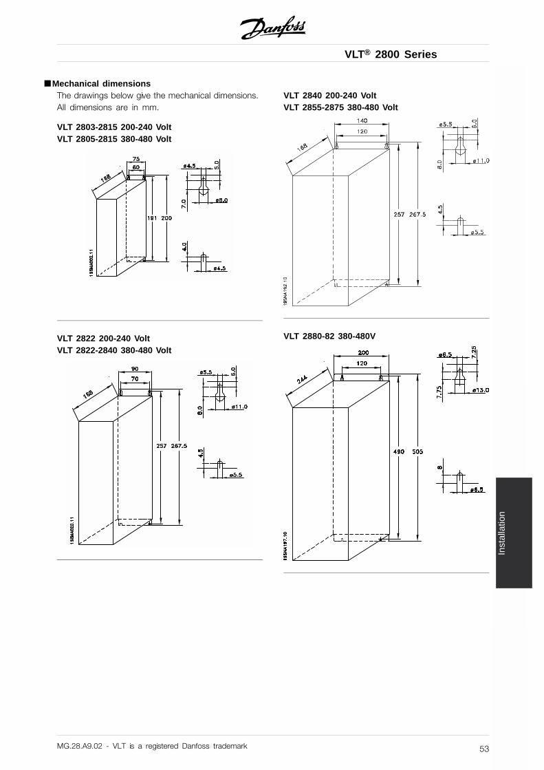
VLT® 2800 Series
Inst
alla
tion
■ Mechanical dimensionsThe drawings below give the mechanical dimensions.All dimensions are in mm.
VLT 2803-2815 200-240 VoltVLT 2805-2815 380-480 Volt
VLT 2822 200-240 VoltVLT 2822-2840 380-480 Volt
VLT 2840 200-240 VoltVLT 2855-2875 380-480 Volt
VLT 2880-82 380-480V
MG.28.A9.02 - VLT is a registered Danfoss trademark 53
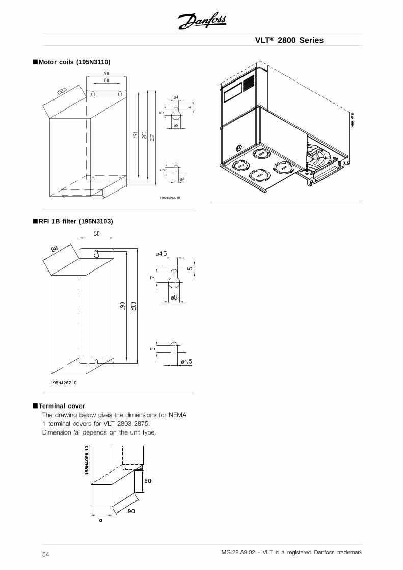
VLT® 2800 Series
■ Motor coils (195N3110)
■ RFI 1B filter (195N3103)
■ Terminal coverThe drawing below gives the dimensions for NEMA1 terminal covers for VLT 2803-2875.Dimension ’a’ depends on the unit type.
MG.28.A9.02 - VLT is a registered Danfoss trademark54
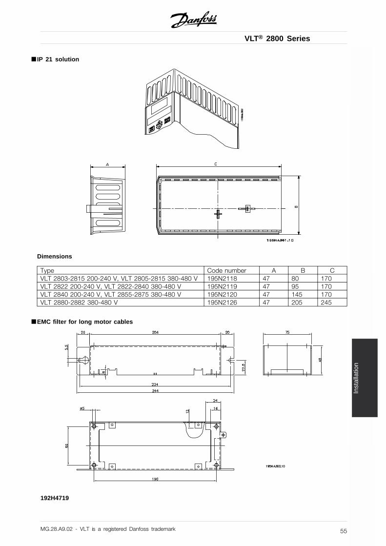
VLT® 2800 Series
Inst
alla
tion
■ IP 21 solution
Dimensions
Type Code number A B CVLT 2803-2815 200-240 V, VLT 2805-2815 380-480 V 195N2118 47 80 170VLT 2822 200-240 V, VLT 2822-2840 380-480 V 195N2119 47 95 170VLT 2840 200-240 V, VLT 2855-2875 380-480 V 195N2120 47 145 170VLT 2880-2882 380-480 V 195N2126 47 205 245
■ EMC filter for long motor cables
192H4719
MG.28.A9.02 - VLT is a registered Danfoss trademark 55
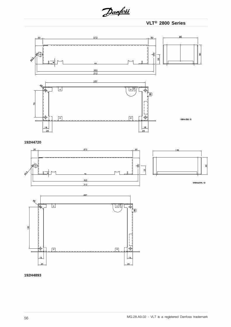
VLT® 2800 Series
192H4720
192H4893
MG.28.A9.02 - VLT is a registered Danfoss trademark56
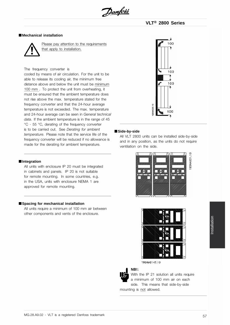
VLT® 2800 Series
Inst
alla
tion
■ Mechanical installation
Please pay attention to the requirementsthat apply to installation.
The frequency converter iscooled by means of air circulation. For the unit to beable to release its cooling air, the minimum freedistance above and below the unit must be minimum100 mm . To protect the unit from overheating, itmust be ensured that the ambient temperature doesnot rise above the max. temperature stated for thefrequency converter and that the 24-hour averagetemperature is not exceeded. The max. temperatureand 24-hour average can be seen in General technicaldata. If the ambient temperature is in the range of 45°C - 55 °C, derating of the frequency converteris to be carried out. See Derating for ambienttemperature. Please note that the service life of thefrequency converter will be reduced if no allowance ismade for the derating for ambient temperature.
■ IntegrationAll units with enclosure IP 20 must be integratedin cabinets and panels. IP 20 is not suitablefor remote mounting. In some countries, e.g.in the USA, units with enclosure NEMA 1 areapproved for remote mounting.
■ Spacing for mechanical installationAll units require a minimum of 100 mm air betweenother components and vents of the enclosure.
■ Side-by-sideAll VLT 2800 units can be installed side-by-sideand in any position, as the units do not requireventilation on the side.
NB!:With the IP 21 solution all units requirea minimum of 100 mm air on eachside. This means that side-by-side
mounting is not allowed.
MG.28.A9.02 - VLT is a registered Danfoss trademark 57
VLT® 2800 Series
■ General information about electrical installation
■ High voltage warning
The voltage of the frequency converteris dangerous whenever the equipment isconnected to mains. Incorrect installation
of the motor or frequency converter may causedamage to the equipment, serious injury or death.Comply with the instructions in this manual, as well asnational and local rules and safety regulations.Touching the electrical parts may be fatal - even afterthe equipment has been disconnected from mains:Wait at least 4 minutes for current dissipate.
NB!:It is the responsibility of the user or installerto ensure correct earthing and protection inaccordance with national and local standards.
■ EarthingComply with the following at installation:
• Safety earthing: The drive has a high leakagecurrent and must be earthed properly for safety.Follow all local safety regulations.
• High frequency earthing: Keep earthingconnections as short as possible.
Connect all earthing systems to ensure the lowestpossible conductor impedance. The lowest possibleconductor impedance is achieved by keeping theconductor as short as possible and by grounding withthe greatest possible surface area. If multiple drivesare installed in a cabinet, the cabinet backplate, whichmust be made of metal, should be used as a jointearth reference plate. The drives must be fitted to thebackplate at the lowest possible impedance.
To achieve low impedance, connect the drive to thebackplate with the drive fastening bolts. Removeall paint from the contact points.
■ Extra protectionRCD relays, multiple protective earthing or earthingcan be used as extra protection, provided that localsafety regulations are complied with. In the case of anearth fault, a DC content may develop in the faultycurrent. Never use an RCD (ELCB relay), type A, asit is not suitable for DC faulty currents. If RCD relaysare used, local regulations must be complied with.If RCD relays are used, they must be:
- Suitable for protecting equipment with a DC contentin the faulty current (3-phase bridge rectifier).
- Suitable for a pulse-shaped, brief dischargeon power-up.
- Suitable for a high leakage current.
N must be connected before L1 for single phase 200V reduced leakage current units (type code R4).
■ High voltage testA high voltage test can be performed byshort-circuiting terminals U, V, W, L1, L2 and L3,and applying max. 2160 V DC in 1 sec. betweenthis short-circuit and terminal 95.
MG.28.A9.02 - VLT is a registered Danfoss trademark58
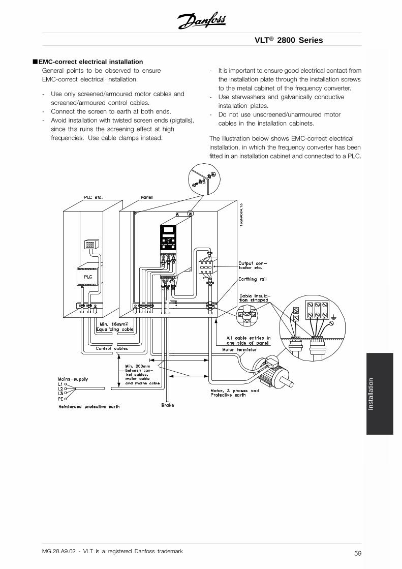
VLT® 2800 Series
Inst
alla
tion
■ EMC-correct electrical installationGeneral points to be observed to ensureEMC-correct electrical installation.
- Use only screened/armoured motor cables andscreened/armoured control cables.
- Connect the screen to earth at both ends.- Avoid installation with twisted screen ends (pigtails),
since this ruins the screening effect at highfrequencies. Use cable clamps instead.
- It is important to ensure good electrical contact fromthe installation plate through the installation screwsto the metal cabinet of the frequency converter.
- Use starwashers and galvanically conductiveinstallation plates.
- Do not use unscreened/unarmoured motorcables in the installation cabinets.
The illustration below shows EMC-correct electricalinstallation, in which the frequency converter has beenfitted in an installation cabinet and connected to a PLC.
MG.28.A9.02 - VLT is a registered Danfoss trademark 59
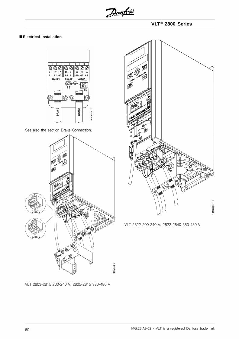
VLT® 2800 Series
■ Electrical installation
See also the section Brake Connection.
VLT 2803-2815 200-240 V, 2805-2815 380-480 V
VLT 2822 200-240 V, 2822-2840 380-480 V
MG.28.A9.02 - VLT is a registered Danfoss trademark60
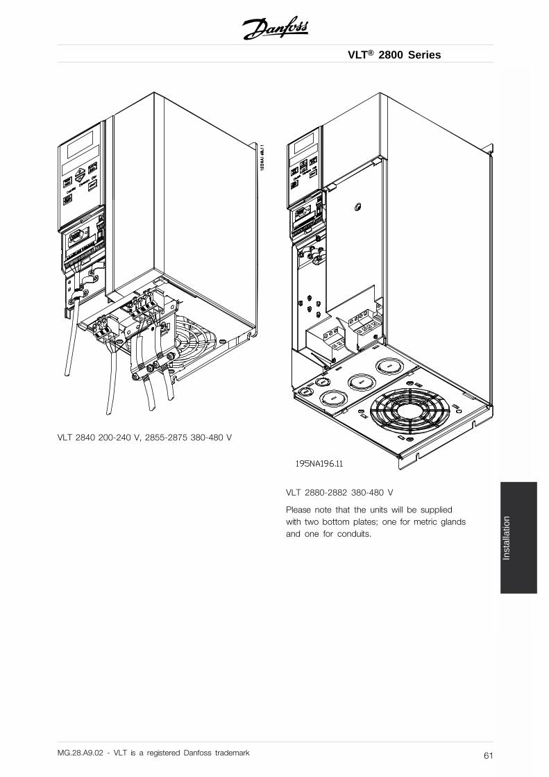
VLT® 2800 Series
Inst
alla
tion
VLT 2840 200-240 V, 2855-2875 380-480 V
VLT 2880-2882 380-480 V
Please note that the units will be suppliedwith two bottom plates; one for metric glandsand one for conduits.
MG.28.A9.02 - VLT is a registered Danfoss trademark 61
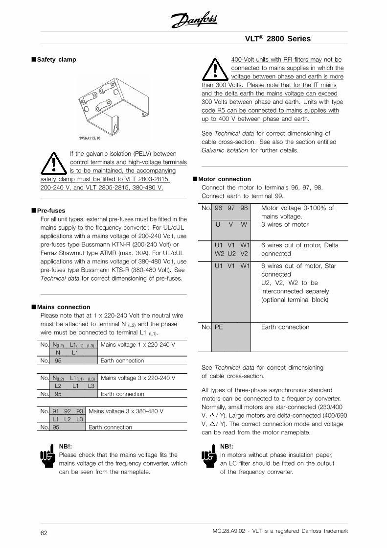
VLT® 2800 Series
■ Safety clamp
If the galvanic isolation (PELV) betweencontrol terminals and high-voltage terminalsis to be maintained, the accompanying
safety clamp must be fitted to VLT 2803-2815,200-240 V, and VLT 2805-2815, 380-480 V.
■ Pre-fusesFor all unit types, external pre-fuses must be fitted in themains supply to the frequency converter. For UL/cULapplications with a mains voltage of 200-240 Volt, usepre-fuses type Bussmann KTN-R (200-240 Volt) orFerraz Shawmut type ATMR (max. 30A). For UL/cULapplications with a mains voltage of 380-480 Volt, usepre-fuses type Bussmann KTS-R (380-480 Volt). SeeTechnical data for correct dimensioning of pre-fuses.
■ Mains connectionPlease note that at 1 x 220-240 Volt the neutral wiremust be attached to terminal N (L2) and the phasewire must be connected to terminal L1 (L1).
No. N(L2) L1(L1) (L3) Mains voltage 1 x 220-240 VN L1
No. 95 Earth connection
No. N(L2) L1(L1) (L3) Mains voltage 3 x 220-240 VL2 L1 L3
No. 95 Earth connection
No. 91 92 93 Mains voltage 3 x 380-480 VL1 L2 L3
No. 95 Earth connection
NB!:Please check that the mains voltage fits themains voltage of the frequency converter, whichcan be seen from the nameplate.
400-Volt units with RFI-filters may not beconnected to mains supplies in which thevoltage between phase and earth is more
than 300 Volts. Please note that for the IT mainsand the delta earth the mains voltage can exceed300 Volts between phase and earth. Units with typecode R5 can be connected to mains supplies withup to 400 V between phase and earth.
See Technical data for correct dimensioning ofcable cross-section. See also the section entitledGalvanic isolation for further details.
■ Motor connectionConnect the motor to terminals 96, 97, 98.Connect earth to terminal 99.
No. 96 97 98 Motor voltage 0-100% ofmains voltage.
U V W 3 wires of motor
U1W2
V1U2
W1V2
6 wires out of motor, Deltaconnected
U1 V1 W1 6 wires out of motor, StarconnectedU2, V2, W2 to beinterconnected separely(optional terminal block)
No. PE Earth connection
See Technical data for correct dimensioningof cable cross-section.
All types of three-phase asynchronous standardmotors can be connected to a frequency converter.Normally, small motors are star-connected (230/400V, / Y). Large motors are delta-connected (400/690V, / Y). The correct connection mode and voltagecan be read from the motor nameplate.
NB!:In motors without phase insulation paper,an LC filter should be fitted on the outputof the frequency converter.
MG.28.A9.02 - VLT is a registered Danfoss trademark62
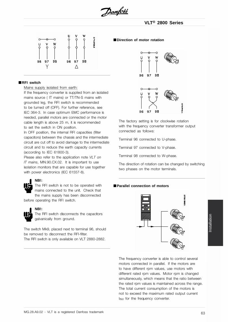
VLT® 2800 Series
Inst
alla
tion
■ RFI switchMains supply isolated from earth:If the frequency converter is supplied from an isolatedmains source ( IT mains) or TT/TN-S mains withgrounded leg, the RFI switch is recommendedto be turned off (OFF). For further reference, seeIEC 364-3. In case optimum EMC performance isneeded, parallel motors are connected or the motorcable length is above 25 m, it is recommendedto set the switch in ON position.In OFF position, the internal RFI capacities (filtercapacitors) between the chassis and the intermediatecircuit are cut off to avoid damage to the intermediatecircuit and to reduce the earth capacity currents(according to IEC 61800-3).Please also refer to the application note VLT onIT mains, MN.90.CX.02. It is important to useisolation monitors that are capable for use togetherwith power electronics (IEC 61557-8).
NB!:The RFI switch is not to be operated withmains connected to the unit. Check thatthe mains supply has been disconnected
before operating the RFI switch.
NB!:The RFI switch disconnects the capacitorsgalvanically from ground.
The switch Mk9, placed next to terminal 96, shouldbe removed to disconnect the RFI-filter.The RFI switch is only available on VLT 2880-2882.
■ Direction of motor rotation
The factory setting is for clockwise rotationwith the frequency converter transformer outputconnected as follows:
Terminal 96 connected to U-phase.
Terminal 97 connected to V-phase.
Terminal 98 connected to W-phase.
The direction of rotation can be changed by switchingtwo phases on the motor terminals.
■ Parallel connection of motors
The frequency converter is able to control severalmotors connected in parallel. If the motors areto have different rpm values, use motors withdifferent rated rpm values. Motor rpm is changedsimultaneously, which means that the ratio betweenthe rated rpm values is maintained across the range.The total current consumption of the motors isnot to exceed the maximum rated output currentIINV for the frequency converter.
MG.28.A9.02 - VLT is a registered Danfoss trademark 63
VLT® 2800 Series
Problems may arise at the start and at low rpmvalues if the motor sizes are widely different. Thisis because the small motors’ relatively high ohmicresistance in the stator calls for a higher voltageat the start and at low rpm values.
In systems with motors connected in parallel, theelectronic thermal relay (ETR) of the frequencyconverter cannot be used as motor protectionfor the individual motor. For this reason furthermotor protection must be used, e.g. thermistors ineach motor or an individual thermal relay. (Circuitbreakers are not suitable as protection).
NB!:Parameter 107 Automatic motor adaption, AMTcannot be used when motors are connectedin parallel. Parameter 101 Torque characteristic
must be set to Special motor characteristics [8]when motors are connected in parallel.
■ Motor cablesSee Technical data for correct dimensioning of motorcable cross-section and length. Always comply withnational and local regulations on cable cross-section.
NB!:If an unscreened/unarmoured cable is used,some EMC requirements are not complied with,see EMC test results in the Design Guide.
If the EMC specifications regarding emission areto be complied with, the motor cable must bescreened/armoured, unless otherwise stated for theRFI filter in question. It is important to keep the motorcable as short as possible so as to reduce the noiselevel and leakage currents to a minimum. The motorcable screen must be connected to the metal cabinetof the frequency converter and to the metal cabinet ofthe motor. The screen connections are to be madewith the biggest possible surface area (cable clamp).This is enabled by different installation devices indifferent frequency converters. Mounting with twistedscreen ends (pigtails) is to be avoided, since thesespoil the screening effect at high frequencies. If itis necessary to break the screen to install a motorisolator or motor relay, the screen must be continuedat the lowest possible HF impedance.
■ Motor thermal protectionThe electronic thermal relay in UL-approved frequencyconverters has received the UL-approval for singlemotor protection, when parameter 128 Motor thermal
protection has been set for ETR Trip and parameter105 Motor current, IM, N has been programmed tothe rated motor current (see motor nameplate).
■ Brake connection
No. 81 82 Brake resistorR- R+ terminals
The connection cable to the brake resistor mustbe screened/armoured. Connect the screen to themetal cabinet of the frequency converter and to themetal cabinet of the brake resistor by means ofcable clamps. Dimension the cross-section of thebrake cable to match the brake torque.
See the Design Guide for dimensioningof brake resistors.
NB!:Please note that voltages up to 850 VDC occur on the terminals.
■ Earth connectionAs leak current to the earth is higher than 3.5 mA, thefrequency converter must always be earthed accordingto prevailing national and local regulations. Toguarantee that the earth cable has a good mechanicalconnection to terminal 95, the cable cross sectionmust be at least 10 mm2 or 2 rated earth wiresthat are terminated separately. To increase safetyyou can install an RCD (Residual Current Device),which guarantees that the frequency converter tripswhen leak current becomes too high. See alsoRCD Application Note MN.90.GX.02.
MG.28.A9.02 - VLT is a registered Danfoss trademark64
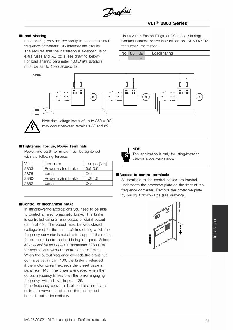
VLT® 2800 Series
Inst
alla
tion
■ Load sharingLoad sharing provides the facility to connect severalfrequency converters’ DC intermediate circuits.This requires that the installation is extended usingextra fuses and AC coils (see drawing below).For load sharing parameter 400 Brake functionmust be set to Load sharing [5].
Use 6.3 mm Faston Plugs for DC (Load Sharing).Contact Danfoss or see instructions no. MI.50.NX.02for further information.
No. 88 89 Loadsharing- +
Note that voltage levels of up to 850 V DCmay occur between terminals 88 and 89.
■ Tightening Torque, Power TerminalsPower and earth terminals must be tightenedwith the following torques:
VLT Terminals Torque [Nm]Power mains brake 0.5-0.62803-
2875 Earth 2-3Power mains brake 1.2-1.52880-
2882 Earth 2-3
■ Control of mechanical brakeIn lifting/lowering applications you need to be ableto control an electromagnetic brake. The brakeis controlled using a relay output or digital output(terminal 46). The output must be kept closed(voltage-free) for the period of time during which thefrequency converter is not able to ’support’ the motor,for example due to the load being too great. SelectMechanical brake control in parameter 323 or 341for applications with an electromagnetic brake.When the output frequency exceeds the brake cutout value set in par. 138, the brake is releasedif the motor current exceeds the preset value inparameter 140. The brake is engaged when theoutput frequency is less than the brake engagingfrequency, which is set in par. 139.If the frequency converter is placed at alarm statusor in an overvoltage situation the mechanicalbrake is cut in immediately.
NB!:This application is only for lifting/loweringwithout a counterbalance.
■ Access to control terminalsAll terminals to the control cables are locatedunderneath the protective plate on the front of thefrequency converter. Remove the protective plateby pulling it downwards (see drawing).
MG.28.A9.02 - VLT is a registered Danfoss trademark 65
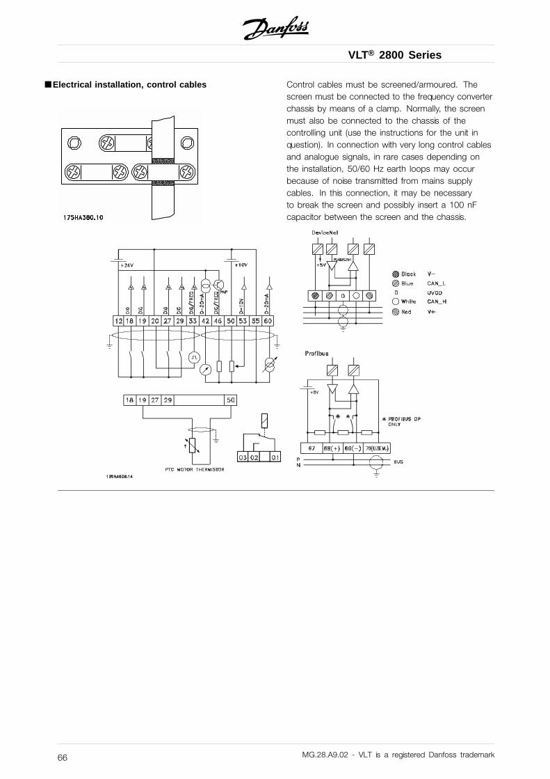
VLT® 2800 Series
■ Electrical installation, control cables Control cables must be screened/armoured. Thescreen must be connected to the frequency converterchassis by means of a clamp. Normally, the screenmust also be connected to the chassis of thecontrolling unit (use the instructions for the unit inquestion). In connection with very long control cablesand analogue signals, in rare cases depending onthe installation, 50/60 Hz earth loops may occurbecause of noise transmitted from mains supplycables. In this connection, it may be necessaryto break the screen and possibly insert a 100 nFcapacitor between the screen and the chassis.
MG.28.A9.02 - VLT is a registered Danfoss trademark66
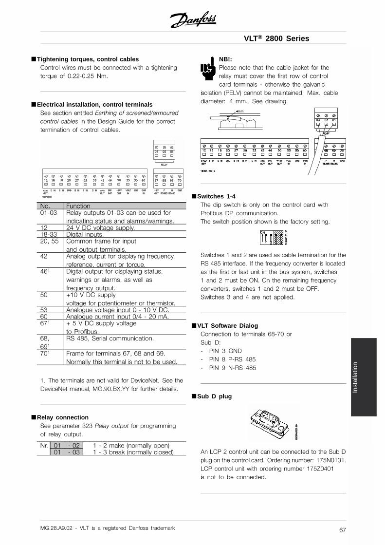
VLT® 2800 Series
Inst
alla
tion
■ Tightening torques, control cablesControl wires must be connected with a tighteningtorque of 0.22-0.25 Nm.
■ Electrical installation, control terminalsSee section entitled Earthing of screened/armouredcontrol cables in the Design Guide for the correcttermination of control cables.
No. Function01-03 Relay outputs 01-03 can be used for
indicating status and alarms/warnings.12 24 V DC voltage supply.18-33 Digital inputs.20, 55 Common frame for input
and output terminals.42 Analog output for displaying frequency,
reference, current or torque.461 Digital output for displaying status,
warnings or alarms, as well asfrequency output.
50 +10 V DC supplyvoltage for potentiometer or thermistor.
53 Analogue voltage input 0 - 10 V DC.60 Analogue current input 0/4 - 20 mA.671 + 5 V DC supply voltage
to Profibus.68,691
RS 485, Serial communication.
701 Frame for terminals 67, 68 and 69.Normally this terminal is not to be used.
1. The terminals are not valid for DeviceNet. See theDeviceNet manual, MG.90.BX.YY for further details.
■ Relay connectionSee parameter 323 Relay output for programmingof relay output.
Nr. 01 - 02 1 - 2 make (normally open)01 - 03 1 - 3 break (normally closed)
NB!:Please note that the cable jacket for therelay must cover the first row of controlcard terminals - otherwise the galvanic
isolation (PELV) cannot be maintained. Max. cablediameter: 4 mm. See drawing.
■ Switches 1-4The dip switch is only on the control card withProfibus DP communication.The switch position shown is the factory setting.
Switches 1 and 2 are used as cable termination for theRS 485 interface. If the frequency converter is locatedas the first or last unit in the bus system, switches1 and 2 must be ON. On the remaining frequencyconverters, switches 1 and 2 must be OFF.Switches 3 and 4 are not applied.
■ VLT Software DialogConnection to terminals 68-70 orSub D:- PIN 3 GND- PIN 8 P-RS 485- PIN 9 N-RS 485
■ Sub D plug
An LCP 2 control unit can be connected to the Sub Dplug on the control card. Ordering number: 175N0131.LCP control unit with ordering number 175Z0401is not to be connected.
MG.28.A9.02 - VLT is a registered Danfoss trademark 67
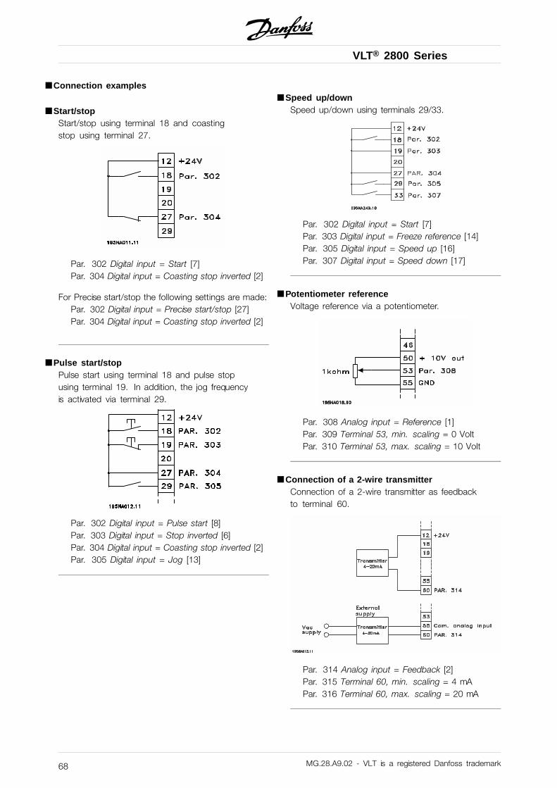
VLT® 2800 Series
■ Connection examples
■ Start/stopStart/stop using terminal 18 and coastingstop using terminal 27.
Par. 302 Digital input = Start [7]Par. 304 Digital input = Coasting stop inverted [2]
For Precise start/stop the following settings are made:Par. 302 Digital input = Precise start/stop [27]Par. 304 Digital input = Coasting stop inverted [2]
■ Pulse start/stopPulse start using terminal 18 and pulse stopusing terminal 19. In addition, the jog frequencyis activated via terminal 29.
Par. 302 Digital input = Pulse start [8]Par. 303 Digital input = Stop inverted [6]Par. 304 Digital input = Coasting stop inverted [2]Par. 305 Digital input = Jog [13]
■ Speed up/downSpeed up/down using terminals 29/33.
Par. 302 Digital input = Start [7]Par. 303 Digital input = Freeze reference [14]Par. 305 Digital input = Speed up [16]Par. 307 Digital input = Speed down [17]
■ Potentiometer referenceVoltage reference via a potentiometer.
Par. 308 Analog input = Reference [1]Par. 309 Terminal 53, min. scaling = 0 VoltPar. 310 Terminal 53, max. scaling = 10 Volt
■ Connection of a 2-wire transmitterConnection of a 2-wire transmitter as feedbackto terminal 60.
Par. 314 Analog input = Feedback [2]Par. 315 Terminal 60, min. scaling = 4 mAPar. 316 Terminal 60, max. scaling = 20 mA
MG.28.A9.02 - VLT is a registered Danfoss trademark68
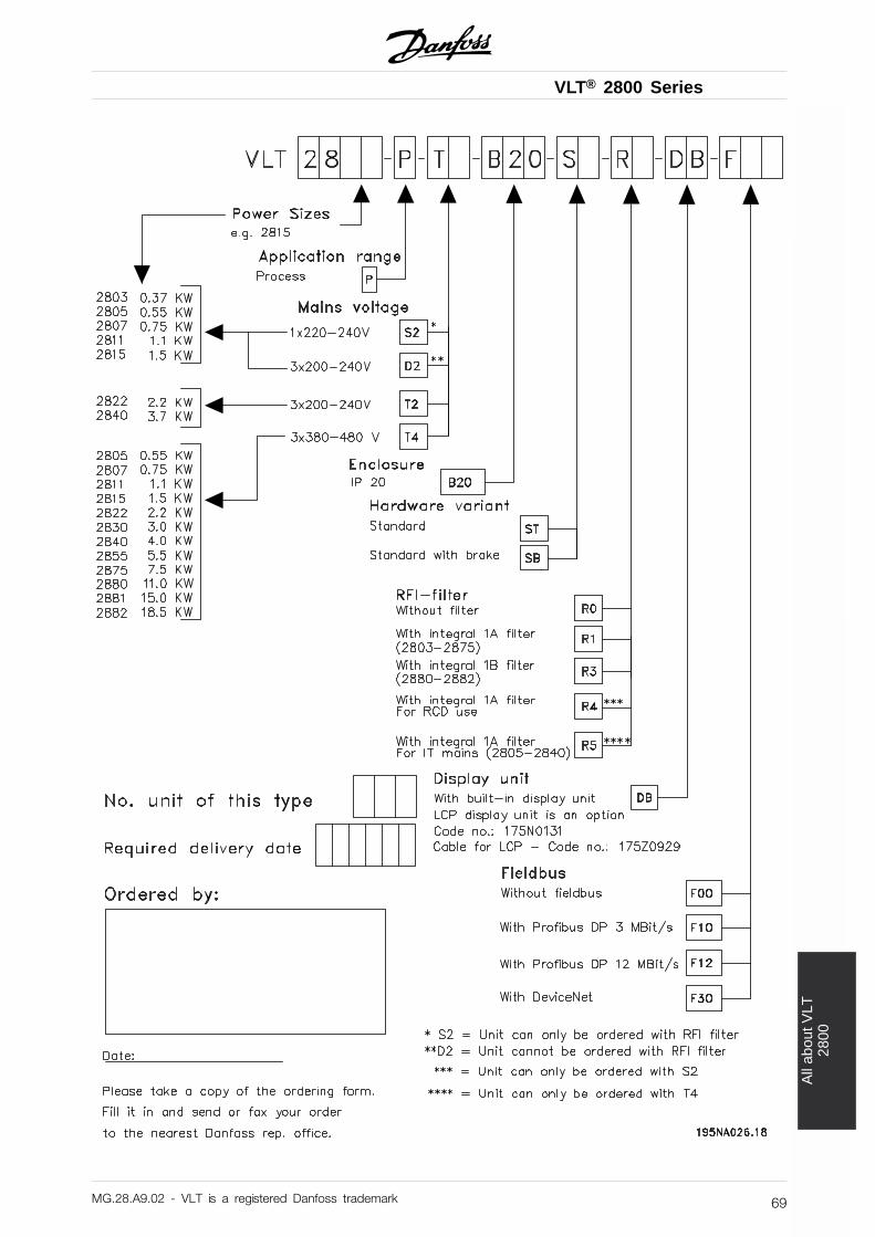
VLT® 2800 Series
All
abou
t VLT
2800
MG.28.A9.02 - VLT is a registered Danfoss trademark 69

VLT® 2800 Series
■ Display readoutFrThe frequency converter shows the presentoutput frequency in Hertz [Hz].
IoThe frequency converter shows the presentoutput current in Amps [A].
UoThe frequency converter shows the presentoutput voltage in Volt [V].
UdThe frequency converter shows the intermediatecircuit voltage in Volt [V].
PoThe frequency converter shows the calculatedoutput in kilowatt [kW].
notrunThis message is shown if an attempt is made tochange a parameter value while the motor is running.Stop the motor to change the parameter value.
LCPThis message is shown if an LCP 2 control unit isfitted and the [QUICK MENU] or [CHANGE DATA]key is activated. If an LCP 2 control unit is fittedyou can only change parameters with that.
HaThe frequency converter shows the present Handmode reference frequency in Herz (Hz).
SCThe frequency converter shows scaled output frequency(the present output frequency x parameter 008).
■ Warnings/alarm messagesA warning or an alarm will appear in the displayas a numerical code Err. xx. A warning willbe shown on the display until the fault hasbeen corrected, while an alarm will continue toflash until the [STOP/RESET] key is activated.The table shows the various warnings and alarms, andwhether the fault locks the frequency converter. Aftera Trip locked the mains supply is cut off and the faultis corrected. The mains supply is reconnected and thefrequency converter is reset. The frequency converter isnow ready. A Trip can be reset manually in three ways:1. Via the operating key [STOP/RESET].2. Via a digital input.3. Via serial communication.
It is also possible to choose an automatic reset inparameter 405 Reset function. When a cross appearsin both warning and alarm, this can mean that awarning comes before an alarm. It can also meanthat it is possible for the user to programme whethera warning or an alarm will appear for a given fault.For example, this is possible in parameter 128 Motorthermal protection. After a trip the motor will coast,and alarm and warning will blink on the frequencyconverter, but if the fault disappears only the alarmwill blink. After a reset the frequency converterwill be ready to start operation again.
MG.28.A9.02 - VLT is a registered Danfoss trademark70
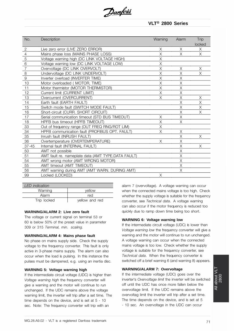
VLT® 2800 Series
All
abou
t VLT
2800
No. Description Warning Alarm Triplocked
2 Live zero error (LIVE ZERO ERROR) X X X4 Mains phase loss (MAINS PHASE LOSS) X X X5 Voltage warning high (DC LINK VOLTAGE HIGH) X6 Voltage warning low (DC LINK VOLTAGE LOW) X7 Overvoltage (DC LINK OVERVOLT) X X X8 Undervoltage (DC LINK UNDERVOLT) X X X9 Inverter overload (INVERTER TIME) X X10 Motor overloaded ( MOTOR, TIME) X X11 Motor thermistor (MOTOR THERMISTOR) X X12 Current limit (CURRENT LIMIT) X X13 Overcurrent (OVERCURRENT) X X X14 Earth fault (EARTH FAULT) X X15 Switch mode fault (SWITCH MODE FAULT) X X16 Short-circuit (CURR. SHORT CIRCUIT) X X17 Serial communication timeout (STD BUS TIMEOUT) X X18 HPFB bus timeout (HPFB TIMEOUT) X X33 Out of frequency range (OUT FREQ RNG/ROT LIM) X34 HPFB communication fault (PROFIBUS OPT. FAULT) X X35 Inrush fault (INRUSH FAULT) X X36 Overtemperature (OVERTEMPERATURE) X X37-45 Internal fault (INTERNAL FAULT) X X50 AMT not possible X51 AMT fault re. nameplate data (AMT TYPE.DATA FAULT) X54 AMT wrong motor (AMT WRONG MOTOR) X55 AMT timeout (AMT TIMEOUT) X56 AMT warning during AMT (AMT WARN. DURING AMT) X99 Locked (LOCKED) X
LED indicationWarning yellowAlarm red
Trip locked yellow and red
WARNING/ALARM 2: Live zero faultThe voltage or current signal on terminal 53 or60 is below 50% of the preset value in parameter309 or 315 Terminal, min. scaling.
WARNING/ALARM 4: Mains phase faultNo phase on mains supply side. Check the supplyvoltage to the frequency converter. This fault is onlyactive in 3-phase mains supply. The alarm can alsooccur when the load is pulsing. In this instance thepulses must be dampened, e.g. using an inertia disc.
WARNING 5: Voltage warning highIf the intermediate circuit voltage (UDC) is higher thanVoltage warning high the frequency converter willgive a warning and the motor will continue to rununchanged. If the UDC remains above the voltagewarning limit, the inverter will trip after a set time. Thetime depends on the device, and is set at 5 - 10sec. Note: The frequency converter will trip with an
alarm 7 (overvoltage). A voltage warning can occurwhen the connected mains voltage is too high. Checkwhether the supply voltage is suitable for the frequencyconverter, see Technical data. A voltage warningcan also occur if the motor frequency is reduced tooquickly due to ramp down time being too short.
WARNING 6: Voltage warning lowIf the intermediate circuit voltage (UDC) is lower thanVoltage warning low the frequency converter will give awarning and the motor will continue to run unchanged.A voltage warning can occur when the connectedmains voltage is too low. Check whether the supplyvoltage is suitable for the frequency converter, seeTechnical data. When the frequency converter isswitched off a brief warning 6 (and warning 8) appears.
WARNING/ALARM 7: OvervoltageIf the intermediate voltage (UDC) goes over theinverter’s Overvoltage limit the inverter will be switchedoff until the UDC has once more fallen below theovervoltage limit. If the UDC remains above theovervoltag limit the inverter will trip after a set time.The time depends on the device, and is set at 5- 10 sec. An overvoltage in the UDC can occur
MG.28.A9.02 - VLT is a registered Danfoss trademark 71
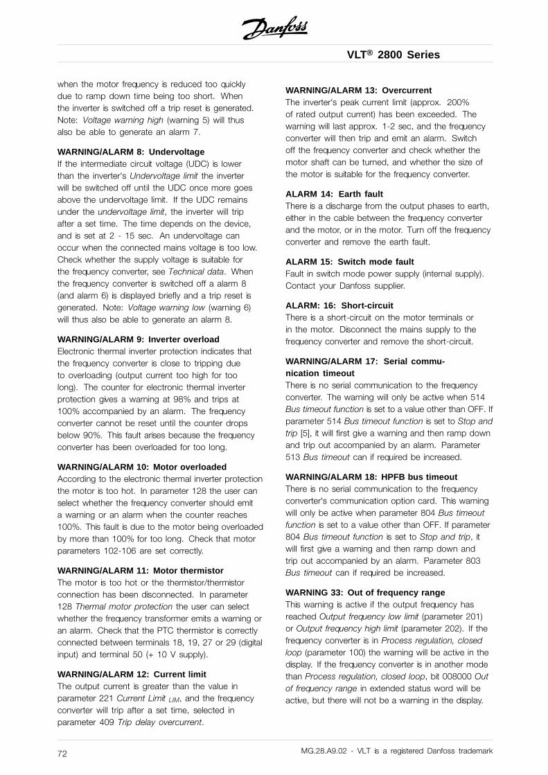
VLT® 2800 Series
when the motor frequency is reduced too quicklydue to ramp down time being too short. Whenthe inverter is switched off a trip reset is generated.Note: Voltage warning high (warning 5) will thusalso be able to generate an alarm 7.
WARNING/ALARM 8: UndervoltageIf the intermediate circuit voltage (UDC) is lowerthan the inverter’s Undervoltage limit the inverterwill be switched off until the UDC once more goesabove the undervoltage limit. If the UDC remainsunder the undervoltage limit, the inverter will tripafter a set time. The time depends on the device,and is set at 2 - 15 sec. An undervoltage canoccur when the connected mains voltage is too low.Check whether the supply voltage is suitable forthe frequency converter, see Technical data. Whenthe frequency converter is switched off a alarm 8(and alarm 6) is displayed briefly and a trip reset isgenerated. Note: Voltage warning low (warning 6)will thus also be able to generate an alarm 8.
WARNING/ALARM 9: Inverter overloadElectronic thermal inverter protection indicates thatthe frequency converter is close to tripping dueto overloading (output current too high for toolong). The counter for electronic thermal inverterprotection gives a warning at 98% and trips at100% accompanied by an alarm. The frequencyconverter cannot be reset until the counter dropsbelow 90%. This fault arises because the frequencyconverter has been overloaded for too long.
WARNING/ALARM 10: Motor overloadedAccording to the electronic thermal inverter protectionthe motor is too hot. In parameter 128 the user canselect whether the frequency converter should emita warning or an alarm when the counter reaches100%. This fault is due to the motor being overloadedby more than 100% for too long. Check that motorparameters 102-106 are set correctly.
WARNING/ALARM 11: Motor thermistorThe motor is too hot or the thermistor/thermistorconnection has been disconnected. In parameter128 Thermal motor protection the user can selectwhether the frequency transformer emits a warning oran alarm. Check that the PTC thermistor is correctlyconnected between terminals 18, 19, 27 or 29 (digitalinput) and terminal 50 (+ 10 V supply).
WARNING/ALARM 12: Current limitThe output current is greater than the value inparameter 221 Current Limit LIM, and the frequencyconverter will trip after a set time, selected inparameter 409 Trip delay overcurrent.
WARNING/ALARM 13: OvercurrentThe inverter’s peak current limit (approx. 200%of rated output current) has been exceeded. Thewarning will last approx. 1-2 sec, and the frequencyconverter will then trip and emit an alarm. Switchoff the frequency converter and check whether themotor shaft can be turned, and whether the size ofthe motor is suitable for the frequency converter.
ALARM 14: Earth faultThere is a discharge from the output phases to earth,either in the cable between the frequency converterand the motor, or in the motor. Turn off the frequencyconverter and remove the earth fault.
ALARM 15: Switch mode faultFault in switch mode power supply (internal supply).Contact your Danfoss supplier.
ALARM: 16: Short-circuitThere is a short-circuit on the motor terminals orin the motor. Disconnect the mains supply to thefrequency converter and remove the short-circuit.
WARNING/ALARM 17: Serial commu-nication timeoutThere is no serial communication to the frequencyconverter. The warning will only be active when 514Bus timeout function is set to a value other than OFF. Ifparameter 514 Bus timeout function is set to Stop andtrip [5], it will first give a warning and then ramp downand trip out accompanied by an alarm. Parameter513 Bus timeout can if required be increased.
WARNING/ALARM 18: HPFB bus timeoutThere is no serial communication to the frequencyconverter’s communication option card. This warningwill only be active when parameter 804 Bus timeoutfunction is set to a value other than OFF. If parameter804 Bus timeout function is set to Stop and trip, itwill first give a warning and then ramp down andtrip out accompanied by an alarm. Parameter 803Bus timeout can if required be increased.
WARNING 33: Out of frequency rangeThis warning is active if the output frequency hasreached Output frequency low limit (parameter 201)or Output frequency high limit (parameter 202). If thefrequency converter is in Process regulation, closedloop (parameter 100) the warning will be active in thedisplay. If the frequency converter is in another modethan Process regulation, closed loop, bit 008000 Outof frequency range in extended status word will beactive, but there will not be a warning in the display.
MG.28.A9.02 - VLT is a registered Danfoss trademark72
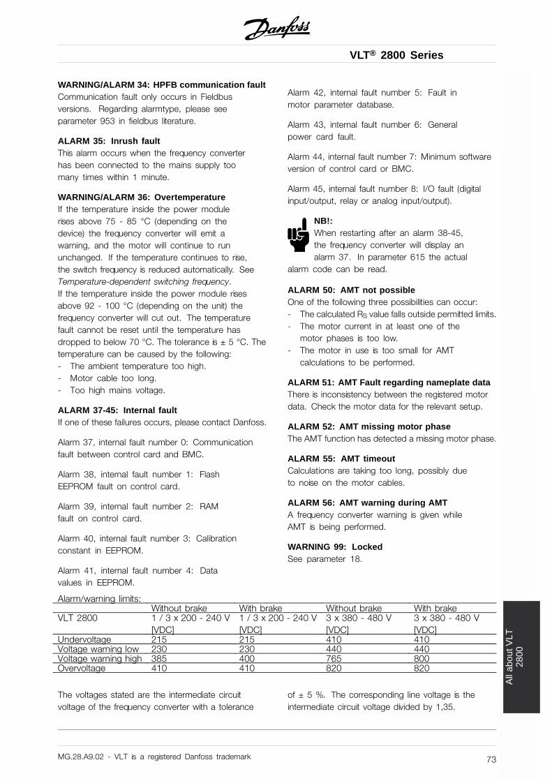
VLT® 2800 Series
All
abou
t VLT
2800
WARNING/ALARM 34: HPFB communication faultCommunication fault only occurs in Fieldbusversions. Regarding alarmtype, please seeparameter 953 in fieldbus literature.
ALARM 35: Inrush faultThis alarm occurs when the frequency converterhas been connected to the mains supply toomany times within 1 minute.
WARNING/ALARM 36: OvertemperatureIf the temperature inside the power modulerises above 75 - 85 °C (depending on thedevice) the frequency converter will emit awarning, and the motor will continue to rununchanged. If the temperature continues to rise,the switch frequency is reduced automatically. SeeTemperature-dependent switching frequency.If the temperature inside the power module risesabove 92 - 100 °C (depending on the unit) thefrequency converter will cut out. The temperaturefault cannot be reset until the temperature hasdropped to below 70 °C. The tolerance is ± 5 °C. Thetemperature can be caused by the following:- The ambient temperature too high.- Motor cable too long.- Too high mains voltage.
ALARM 37-45: Internal faultIf one of these failures occurs, please contact Danfoss.
Alarm 37, internal fault number 0: Communicationfault between control card and BMC.
Alarm 38, internal fault number 1: FlashEEPROM fault on control card.
Alarm 39, internal fault number 2: RAMfault on control card.
Alarm 40, internal fault number 3: Calibrationconstant in EEPROM.
Alarm 41, internal fault number 4: Datavalues in EEPROM.
Alarm 42, internal fault number 5: Fault inmotor parameter database.
Alarm 43, internal fault number 6: Generalpower card fault.
Alarm 44, internal fault number 7: Minimum softwareversion of control card or BMC.
Alarm 45, internal fault number 8: I/O fault (digitalinput/output, relay or analog input/output).
NB!:When restarting after an alarm 38-45,the frequency converter will display analarm 37. In parameter 615 the actual
alarm code can be read.
ALARM 50: AMT not possibleOne of the following three possibilities can occur:- The calculated RS value falls outside permitted limits.- The motor current in at least one of the
motor phases is too low.- The motor in use is too small for AMT
calculations to be performed.
ALARM 51: AMT Fault regarding nameplate dataThere is inconsistency between the registered motordata. Check the motor data for the relevant setup.
ALARM 52: AMT missing motor phaseThe AMT function has detected a missing motor phase.
ALARM 55: AMT timeoutCalculations are taking too long, possibly dueto noise on the motor cables.
ALARM 56: AMT warning during AMTA frequency converter warning is given whileAMT is being performed.
WARNING 99: LockedSee parameter 18.
Alarm/warning limits:Without brake With brake Without brake With brake
VLT 2800 1 / 3 x 200 - 240 V[VDC]
1 / 3 x 200 - 240 V[VDC]
3 x 380 - 480 V[VDC]
3 x 380 - 480 V[VDC]
Undervoltage 215 215 410 410Voltage warning low 230 230 440 440Voltage warning high 385 400 765 800Overvoltage 410 410 820 820
The voltages stated are the intermediate circuitvoltage of the frequency converter with a tolerance
of ± 5 %. The corresponding line voltage is theintermediate circuit voltage divided by 1,35.
MG.28.A9.02 - VLT is a registered Danfoss trademark 73
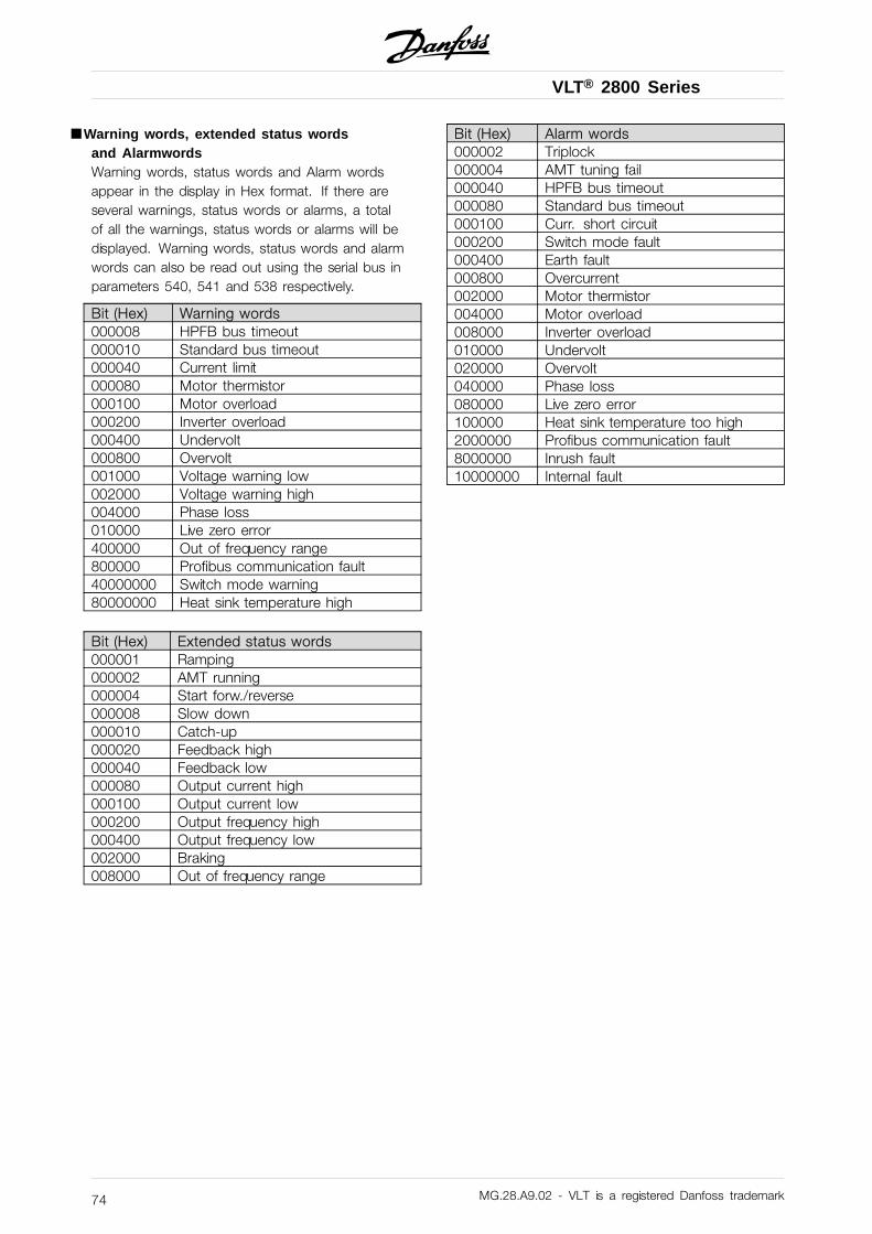
VLT® 2800 Series
■ Warning words, extended status wordsand AlarmwordsWarning words, status words and Alarm wordsappear in the display in Hex format. If there areseveral warnings, status words or alarms, a totalof all the warnings, status words or alarms will bedisplayed. Warning words, status words and alarmwords can also be read out using the serial bus inparameters 540, 541 and 538 respectively.
Bit (Hex) Warning words000008 HPFB bus timeout000010 Standard bus timeout000040 Current limit000080 Motor thermistor000100 Motor overload000200 Inverter overload000400 Undervolt000800 Overvolt001000 Voltage warning low002000 Voltage warning high004000 Phase loss010000 Live zero error400000 Out of frequency range800000 Profibus communication fault40000000 Switch mode warning80000000 Heat sink temperature high
Bit (Hex) Extended status words000001 Ramping000002 AMT running000004 Start forw./reverse000008 Slow down000010 Catch-up000020 Feedback high000040 Feedback low000080 Output current high000100 Output current low000200 Output frequency high000400 Output frequency low002000 Braking008000 Out of frequency range
Bit (Hex) Alarm words000002 Triplock000004 AMT tuning fail000040 HPFB bus timeout000080 Standard bus timeout000100 Curr. short circuit000200 Switch mode fault000400 Earth fault000800 Overcurrent002000 Motor thermistor004000 Motor overload008000 Inverter overload010000 Undervolt020000 Overvolt040000 Phase loss080000 Live zero error100000 Heat sink temperature too high2000000 Profibus communication fault8000000 Inrush fault10000000 Internal fault
MG.28.A9.02 - VLT is a registered Danfoss trademark74
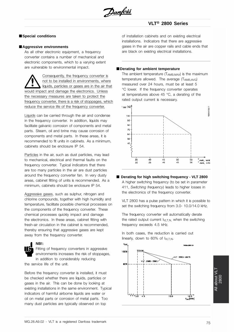
VLT® 2800 Series
All
abou
t VLT
2800
■ Special conditions
■ Aggressive environmentsAs all other electronic equipment, a frequencyconverter contains a number of mechanical andelectronic components, which to a varying extentare vulnerable to environmental impact.
Consequently, the frequency converter isnot to be installed in environments, whereliquids, particles or gases are in the air that
would impact and damage the electronics. Unlessthe necessary measures are taken to protect thefrequency converter, there is a risk of stoppages, whichreduce the service life of the frequency converter.
Liquids can be carried through the air and condensein the frequency converter. In addition, liquids mayfacilitate galvanic corrosion of components and metalparts. Steam, oil and brine may cause corrosion ofcomponents and metal parts. In these areas, it isrecommended to fit units in cabinets. As a minimum,cabinets should be enclosure IP 54.
Particles in the air, such as dust particles, may leadto mechanical, electrical and thermal faults on thefrequency converter. Typical indicators that thereare too many particles in the air are dust particlesaround the frequency converter fan. In very dustyareas, cabinet fitting of units is recommended. As aminimum, cabinets should be enclosure IP 54.
Aggressive gases, such as sulphur, nitrogen andchlorine compounds, together with high humidity andtemperature, facilitate possible chemical processes onthe components of the frequency converter. Thesechemical processes quickly impact and damagethe electronics. In these areas, cabinet fitting withfresh-air circulation in the cabinet is recommended,thereby ensuring that aggressive gases are keptaway from the frequency converter.
NB!:Fitting of frequency converters in aggressiveenvironments increases the risk of stoppages,in addition to considerably reducing
the service life of the unit.
Before the frequency converter is installed, it mustbe checked whether there are liquids, particles orgases in the air. This can be done by looking atexisting installations in the same environment. Typicalindicators of harmful airborne liquids are water oroil on metal parts or corrosion of metal parts. Toomany dust particles are typically observed on top
of installation cabinets and on existing electricalinstallations. Indicators that there are aggressivegases in the air are copper rails and cable ends thatare black on existing electrical installations.
■ Derating for ambient temperatureThe ambient temperature (TAMB,MAX) is the maximumtemperature allowed. The average (TAMB,AVG)measured over 24 hours, must be at least 5°C lower. If the frequency converter operatesat temperatures above 45 °C, a derating of therated output current is necessary.
■ Derating for high switching frequency - VLT 2800A higher switching frequency (to be set in parameter411, Switching frequency) leads to higher losses inthe electronics of the frequency converter.
VLT 2800 has a pulse pattern in which it is possible toset the switching frequency from 3.0- 10.0/14.0 kHz.
The frequency converter will automatically deratethe rated output current IVLT,N, when the switchingfrequency exceeds 4.5 kHz.
In both cases, the reduction is carried outlinearly, down to 60% of IVLT,N.
MG.28.A9.02 - VLT is a registered Danfoss trademark 75
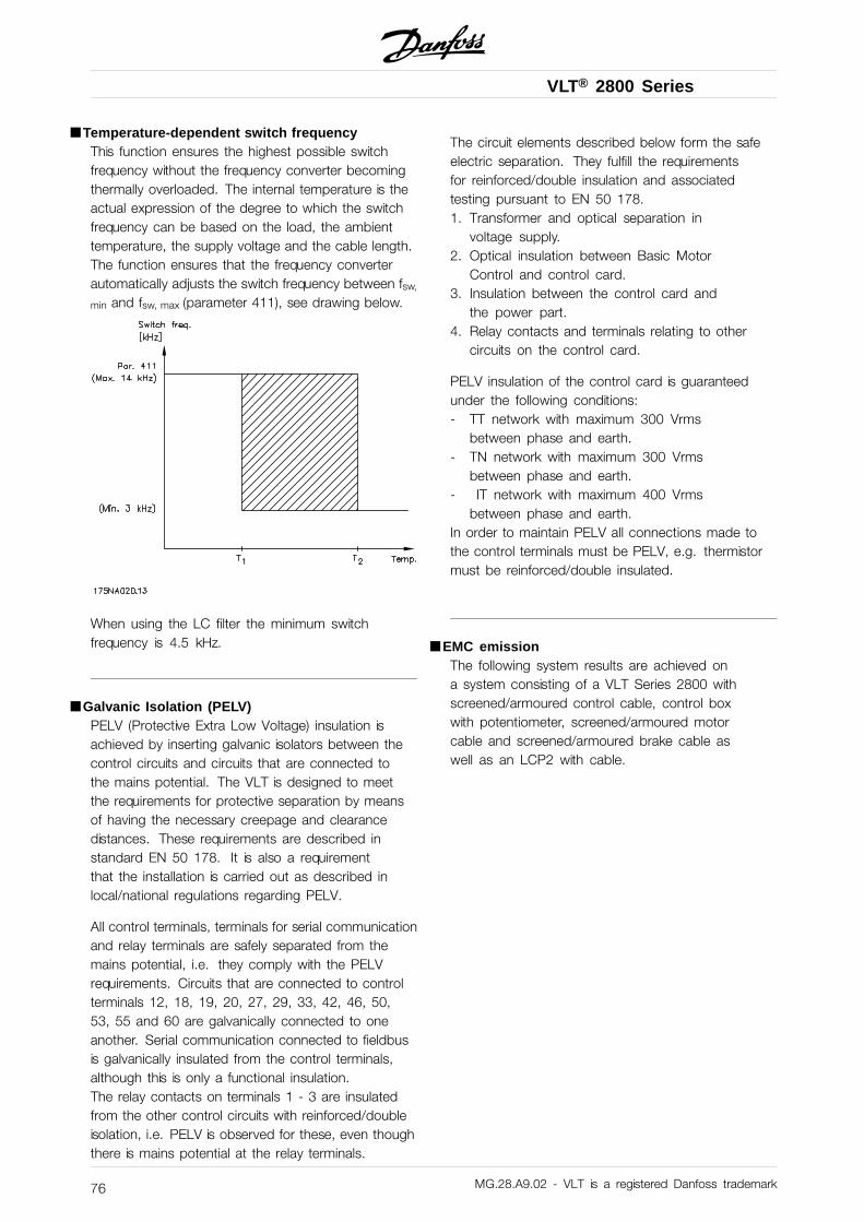
VLT® 2800 Series
■ Temperature-dependent switch frequencyThis function ensures the highest possible switchfrequency without the frequency converter becomingthermally overloaded. The internal temperature is theactual expression of the degree to which the switchfrequency can be based on the load, the ambienttemperature, the supply voltage and the cable length.The function ensures that the frequency converterautomatically adjusts the switch frequency between fsw,
min and fsw, max (parameter 411), see drawing below.
When using the LC filter the minimum switchfrequency is 4.5 kHz.
■ Galvanic Isolation (PELV)PELV (Protective Extra Low Voltage) insulation isachieved by inserting galvanic isolators between thecontrol circuits and circuits that are connected tothe mains potential. The VLT is designed to meetthe requirements for protective separation by meansof having the necessary creepage and clearancedistances. These requirements are described instandard EN 50 178. It is also a requirementthat the installation is carried out as described inlocal/national regulations regarding PELV.
All control terminals, terminals for serial communicationand relay terminals are safely separated from themains potential, i.e. they comply with the PELVrequirements. Circuits that are connected to controlterminals 12, 18, 19, 20, 27, 29, 33, 42, 46, 50,53, 55 and 60 are galvanically connected to oneanother. Serial communication connected to fieldbusis galvanically insulated from the control terminals,although this is only a functional insulation.The relay contacts on terminals 1 - 3 are insulatedfrom the other control circuits with reinforced/doubleisolation, i.e. PELV is observed for these, even thoughthere is mains potential at the relay terminals.
The circuit elements described below form the safeelectric separation. They fulfill the requirementsfor reinforced/double insulation and associatedtesting pursuant to EN 50 178.1. Transformer and optical separation in
voltage supply.2. Optical insulation between Basic Motor
Control and control card.3. Insulation between the control card and
the power part.4. Relay contacts and terminals relating to other
circuits on the control card.
PELV insulation of the control card is guaranteedunder the following conditions:- TT network with maximum 300 Vrms
between phase and earth.- TN network with maximum 300 Vrms
between phase and earth.- IT network with maximum 400 Vrms
between phase and earth.In order to maintain PELV all connections made tothe control terminals must be PELV, e.g. thermistormust be reinforced/double insulated.
■ EMC emissionThe following system results are achieved ona system consisting of a VLT Series 2800 withscreened/armoured control cable, control boxwith potentiometer, screened/armoured motorcable and screened/armoured brake cable aswell as an LCP2 with cable.
MG.28.A9.02 - VLT is a registered Danfoss trademark76
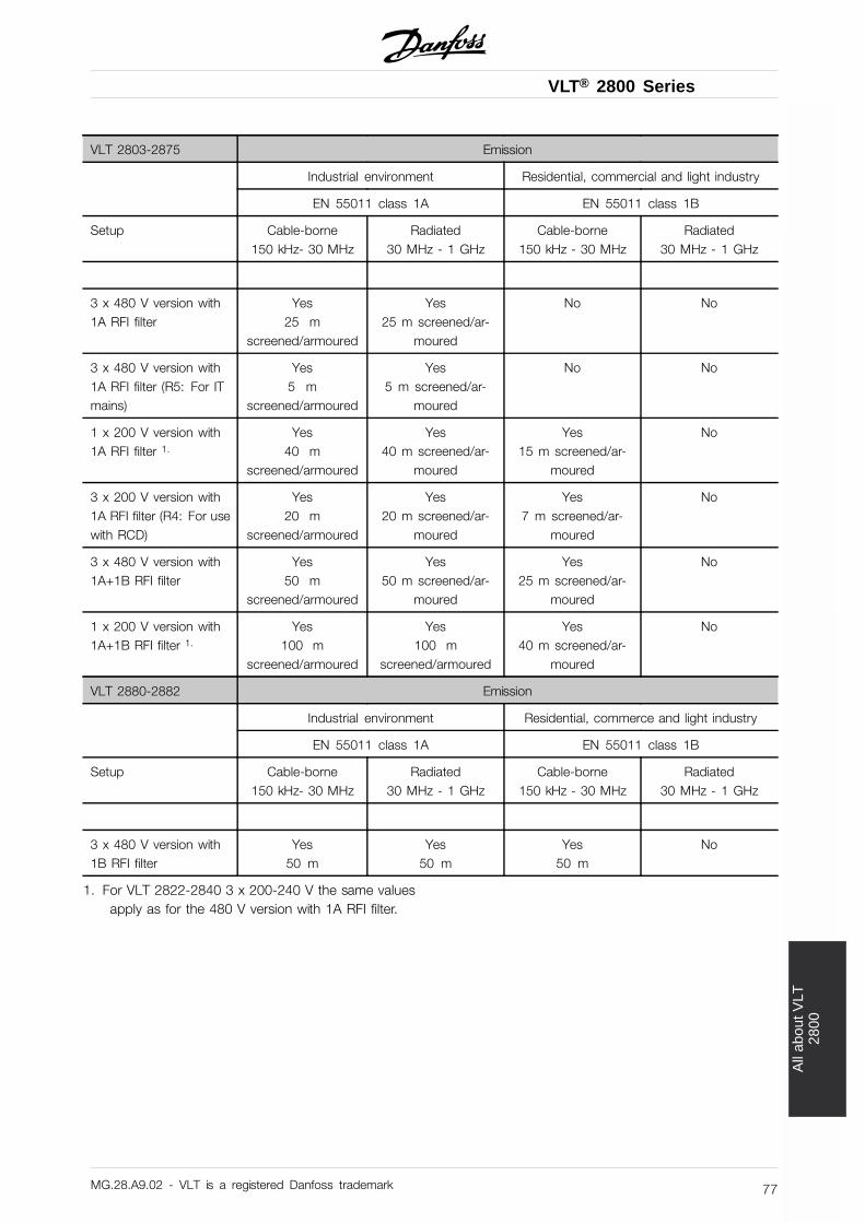
VLT® 2800 Series
All
abou
t VLT
2800
VLT 2803-2875 Emission
Industrial environment Residential, commercial and light industry
EN 55011 class 1A EN 55011 class 1B
Setup Cable-borne150 kHz- 30 MHz
Radiated30 MHz - 1 GHz
Cable-borne150 kHz - 30 MHz
Radiated30 MHz - 1 GHz
3 x 480 V version with1A RFI filter
Yes25 m
screened/armoured
Yes25 m screened/ar-
moured
No No
3 x 480 V version with1A RFI filter (R5: For ITmains)
Yes5 m
screened/armoured
Yes5 m screened/ar-
moured
No No
1 x 200 V version with1A RFI filter 1.
Yes40 m
screened/armoured
Yes40 m screened/ar-
moured
Yes15 m screened/ar-
moured
No
3 x 200 V version with1A RFI filter (R4: For usewith RCD)
Yes20 m
screened/armoured
Yes20 m screened/ar-
moured
Yes7 m screened/ar-
moured
No
3 x 480 V version with1A+1B RFI filter
Yes50 m
screened/armoured
Yes50 m screened/ar-
moured
Yes25 m screened/ar-
moured
No
1 x 200 V version with1A+1B RFI filter 1.
Yes100 m
screened/armoured
Yes100 m
screened/armoured
Yes40 m screened/ar-
moured
No
VLT 2880-2882 Emission
Industrial environment Residential, commerce and light industry
EN 55011 class 1A EN 55011 class 1B
Setup Cable-borne150 kHz- 30 MHz
Radiated30 MHz - 1 GHz
Cable-borne150 kHz - 30 MHz
Radiated30 MHz - 1 GHz
3 x 480 V version with1B RFI filter
Yes50 m
Yes50 m
Yes50 m
No
1. For VLT 2822-2840 3 x 200-240 V the same valuesapply as for the 480 V version with 1A RFI filter.
MG.28.A9.02 - VLT is a registered Danfoss trademark 77
VLT® 2800 Series
• EN 55011: EmissionLimits and methods of measurement ofradio disturbance characteristics of industrial, scien-tific and medical (ISM) high-frequency equipment.
Class 1A:Equipment used in an industrial environment.
Class 1B:Equipment used in areas with a public supply network(residential, commerce and light industry).
■ UL StandardThis device is UL-approved.
MG.28.A9.02 - VLT is a registered Danfoss trademark78
VLT® 2800 Series
All
abou
t VLT
2800
■ General technical data
Mains supply (L1, L2, L3):
Supply voltage VLT 2803-2815 220-240 V (N, L1) ...................................................... 1 x 220/230/240 V ±10%Supply voltage VLT 2803-2840 200-240 V ..................................................... 3 x 200/208/220/230/240 V ±10%Supply voltage VLT 2805-2882 380-480 V ..................................................... 3 x 380/400/415/440/480 V ±10%Supply voltage VLT 2805-2840 (R5) ................................................................................................ 400 V + 10 %Supply frequency ......................................................................................................................... 50/60 Hz ± 3 HzMax. imbalance on supply voltage ........................................................................ ± 2.0% of rated supply voltageTrue Power Factor (λ) ................................................................................................... 0.90 nominal at rated loadDisplacement Power Factor (cos ϕ) ........................................................................................... near unity (> 0.98)Number of connections at supply input L1, L2, L3 ........................................................................... 2 times/min.Max. short-circuit value ......................................................................................................................... 100,000 ASee Special Conditions section in the Design Guide
Output data (U, V, W):
Output voltage ............................................................................................................. 0 - 100% of supply voltageOutput frequency .......................................................................................................... 0.2 - 132 Hz, 1 - 1000 HzRated motor voltage, 200-240 V units ............................................................................. 200/208/220/230/240 VRated motor voltage, 380-480 V units ...................................................................... 380/400/415/440/460/480 VRated motor frequency ............................................................................................................................ 50/60 HzSwitching on output ................................................................................................................................ UnlimitedRamp times ................................................................................................................................. 0.02 - 3600 sec.
Torque characteristics:
Starting torque (parameter 101 Torque characteristic = Constant torque) ..................................... 160% in 1 min.*
Starting torque (parameter 101 Torque characteristics = Variable torque) ..................................... 160% in 1 min.*
Starting torque (parameter 119 High starting torque ) ................................................................ 180% for 0.5 sec.*
Overload torque (parameter 101 Torque characteristic = Constant torque) ................................................... 160%*
Overload torque (parameter 101 Torque characteristic = Variable torque) ..................................................... 160%*
*Percentage relates to frequency converter’s nominal current.
Control card, digital inputs:
Number of programmable digital inputs .............................................................................................................. 5Terminal number ....................................................................................................................... 18, 19, 27, 29, 33Voltage level ........................................................................................................ 0 - 24 V DC (PNP positive logic)Voltage level, logic ’0’ .............................................................................................................................. < 5 V DCVoltage level, logic ’1’ ............................................................................................................................ > 10 V DCMaximum voltage on input ....................................................................................................................... 28 V DCInput resistance, Ri (terminals 18, 19, 27, 29) ................................................................................... approx. 4 kInput resistance, Ri (terminal 33) ...................................................................................................... approx. 2 kAll digital inputs are galvanically isolated from the supply voltage (PELV) and other high-voltage terminals. See section entitled Galvanic Isolation.
MG.28.A9.02 - VLT is a registered Danfoss trademark 79
VLT® 2800 Series
Control card, analog inputs:
Number of analog voltage inputs .................................................................................................................. 1 pcs.Terminal number ................................................................................................................................................ 53Voltage level ...................................................................................................................... 0 - 10 V DC (scaleable)Input resistance, Ri ........................................................................................................................ approx. 10 kMax. voltage .................................................................................................................................................. 20 VNumber of analog current inputs .................................................................................................................. 1 pcs.Terminal number ................................................................................................................................................ 60Current level ...................................................................................................................... 0/4 - 20 mA (scaleable)Input resistance, Ri ......................................................................................................................... approx. 300Max. current ................................................................................................................................................ 30 mAResolution for analog inputs .......................................................................................................................... 10 bitAccuracy of analog inputs ............................................................................................ Max. error 1% of full scaleScan interval .......................................................................................................................................... 13.3 msecThe analog inputs are galvanically isolated from the supply voltage (PELV) and other high-voltage terminals. See section entitled Galvanic Isolation.
Control card, pulse inputs:
Number of programmable pulse inputs ................................................................................................................ 1Terminal number ................................................................................................................................................ 33Max. frequency at terminal 33 ................................................................................................ 67.6 kHz (Push-pull)Max. frequency at terminal 33 ............................................................................................. 5 kHz (open collector)Min. frequency at terminal 33 ......................................................................................................................... 4 HzVoltage level ........................................................................................................ 0 - 24 V DC (PNP positive logic)Voltage level, logic ’0’ .............................................................................................................................. < 5 V DCVoltage level, logic ’1’ ............................................................................................................................ > 10 V DCMaximum voltage on input ....................................................................................................................... 28 V DCInput resistance, Ri .......................................................................................................................... approx. 2 kScan interval .......................................................................................................................................... 13.3 msecResolution ...................................................................................................................................................... 10 bitAccuracy (100 Hz- 1 kHz) terminal 33 ...................................................................... Max. error: 0.5% of full scaleAccuracy (1 kHz - 67.6 kHz) terminal 33 .................................................................. Max. error: 0.1% of full scaleThe pulse input (terminal 33) is galvanically isolated from the supply voltage (PELV) and otherhigh-voltage terminals. See section entitled Galvanic Isolation.
Control card, digital/frequency output:
Number of programmable digital/pulse outputs .......................................................................................... 1 pcs.Terminal number ................................................................................................................................................ 46Voltage level at digital/frequency output ............................................................................ 0 - 24 V DC (O.C PNP)Max. output current at digital/frequency output ......................................................................................... 25 mA.Max. load at digital/frequency output ........................................................................................................... 1 kMax. capacity at frequency output .............................................................................................................. 10 nFMinimum output frequency at frequency output ........................................................................................... 16 HzMaximum output frequency at frequency output ........................................................................................ 10 kHzAccuracy on frequency output ............................................................................... Max. error: 0.2 % of full scaleResolution on frequency output ..................................................................................................................... 10 bitThe digital output is galvanically isolated from the supply voltage (PELV) and other high-voltage terminals. See section entitled Galvanic Isolation.
MG.28.A9.02 - VLT is a registered Danfoss trademark80
VLT® 2800 Series
All
abou
t VLT
2800
Control card, analog output:
Number of programmable analog outputs ............................................................................................................ 1Terminal number ................................................................................................................................................ 42Current range at analog output .......................................................................................................... 0/4 - 20 mAMax. load to common at analog output ...................................................................................................... 500Accuracy on analog output ..................................................................................... Max. error: 1.5 % of full scaleResolution on analog output .......................................................................................................................... 10 bitThe analog output is galvanically isolated from the supply voltage (PELV) and other high-voltage terminals. See section entitled Galvanic Isolation.
Control card, 24 V DC output:
Terminal number ................................................................................................................................................ 12Max. load .................................................................................................................................................. 130 mAThe 24 V DC supply is galvanically isolated from the supply voltage (PELV) , but has the same potentialas the analogue and digital inputs and outputs. See section entitled Galvanic Isolation.
Control card, 10 V DC output:
Terminal number ................................................................................................................................................ 50Output voltage .................................................................................................................................. 10.5 V ±0.5 VMax. load .................................................................................................................................................... 15 mAThe 10 V DC supply is galvanically isolated from the supply voltage (PELV) and other high-voltage terminals. See section entitled Galvanic Isolation.
Control card, RS 485 serial communication:
Terminal number ....................................................................................................... 68 (TX+, RX+), 69 (TX-, RX-)Terminal number 67 ...................................................................................................................................... + 5 VTerminal number 70 ................................................................................... Common for terminals 67, 68 and 69Full galvanic isolation. See section entitled Galvanic Isolation.For DeviceNet units, see VLT 2800 DeviceNet manual, MG.90.BX.YY.
Relay outputs:1)
Number of programmable relay outputs ............................................................................................................... 1Terminal number, control card ............................................................................................ 1-3 (break), 1-2 (make)Max. terminal load (AC1) on 1-3, 1-2, control card ...................................................... 250 V AC, 2 A, 500 V ACMax. terminal load (DC1 (IEC 947)) on 1-3, 1-2, control card ......................... 25 V DC, 2 A /50 V DC, 1A, 50WMin. terminal load (AC/DC) on 1-3, 1-2, control card .................................... 24 V DC 10 mA, 24 V AC 100 mAThe relay contact is separated from the rest of the circuit by strengthened isolation.See section entitled Galvanic Isolation.
1) Rated values for up to 300,000 operations. At inductive loads the number of operations are reduced by50%, alternatively the current can be reduced by 50%, thus the 300,000 operations are maintained.
Cable lengths and cross sections:
Max. motor cable length, screened/armoured cable .................................................................................... 40 mMax. motor cable length, unscreened/unarmoured cable ............................................................................ 75 mMax. motor cable length, screened/armoured cable and motor coil ........................................................... 100 mMax. motor cable length, unscreened/unarmoured cable and motor coil .................................................. 200 mMax. motor cable length, screened/armoured cable and RFI/1B filter ............................................ 200 V, 100 mMax. motor cable length, screened/armoured cable and RFI/1B filter .............................................. 400 V, 25 mMax. motor cable length, screened/armoured cable and RFI 1B/LC filter ......................................... 400 V, 25 mMax. cross section to motor, see next section.Max. cross section to control wires, rigid wire ................................................ 1.5 mm2/16 AWG (2 x 0.75 mm2)
MG.28.A9.02 - VLT is a registered Danfoss trademark 81
VLT® 2800 Series
Max. cross section to control cables, flexible cable .................................................................... 1 mm2/18 AWGMax. cross section to control cables, cable with enclosed core ............................................... 0.5 mm2/20 AWGWhen complying with EN 55011 1A and EN 55011 1B the motor cable must in certaininstances be reduced. See EMC emission.
Control characteristics:
Frequency range ........................................................................................................... 0.2 - 132 Hz, 1 - 1000 HzResolution of output frequency ........................................................................................ 0.013 Hz, 0.2 - 1000 HzRepeat accuracy of Precise start/stop(terminals 18, 19) ................................................................... ≤ ± 0.5 msecSystem response time (terminals 18, 19, 27, 29, 33) ........................................................................ ≤ 26.6 msecSpeed control range (open loop) ................................................................................. 1:10 of synchronous speedSpeed control range (closed loop) ........................................................................... 1:120 of synchronous speedSpeed accuracy (open loop) .................................................................. 150 - 3600 rpm: Max. error of ±23 rpmSpeed accuracy (closed loop) ................................................................ 30 - 3600 rpm: Max. error of ±7.5 rpmAll control characteristics are based on a 4-pole asynchronous motor
Surroundings:
Enclosure ....................................................................................................................................................... IP 20Enclosure with options .............................................................................................................................. NEMA 1Vibration test ................................................................................................................................................. 0.7 gMax. relative humidity .................................................................................................. 5% - 93% during operationAmbient temperature ........................................................................... Max. 45 °C (24-hour average max. 40 °C)Derating for high ambient temperature, see special conditions in the Design GuideMin. ambient temperature during full-scale operation .................................................................................... 0 °CMin. ambient temperature at reduced performance .................................................................................. - 10 °CTemperature during storage/transport .......................................................................................... -25 - +65/70 °CMax. altitude above sea level .................................................................................................................... 1000 mDerating for high air pressure, see special conditions in the Design GuideEMC standards, Emission ............................................................................ EN 61081-2, EN 61800-3, EN 55011EMC standards, Immunity ................................................................................................................................. EN50082-1/2, EN 61000-4-2, EN 61000-4-3, EN 61000-4-4, EN 61000-4-5, EN 61000-4-6, EN 61800-3See section on special conditions in the Design Guide
Safeguards:
• Electronic thermal motor protection against overload.• Temperature monitoring of the power module ensures that the frequency converter cuts
out if the temperature reaches 100 °C. An overload temperature cannot be reset until thetemperature of the power module is below 70 °C.
• The frequency converter is protected against short-circuits on motor terminals U, V, W.• If a mains phase is missing, the frequency converter will cut out.• Monitoring of the intermediate circuit voltage ensures that the frequency converter cuts out if
the intermediate circuit voltage is too low or too high.• The frequency converter is protected against earth fault on motor terminals U, V, W.
MG.28.A9.02 - VLT is a registered Danfoss trademark82
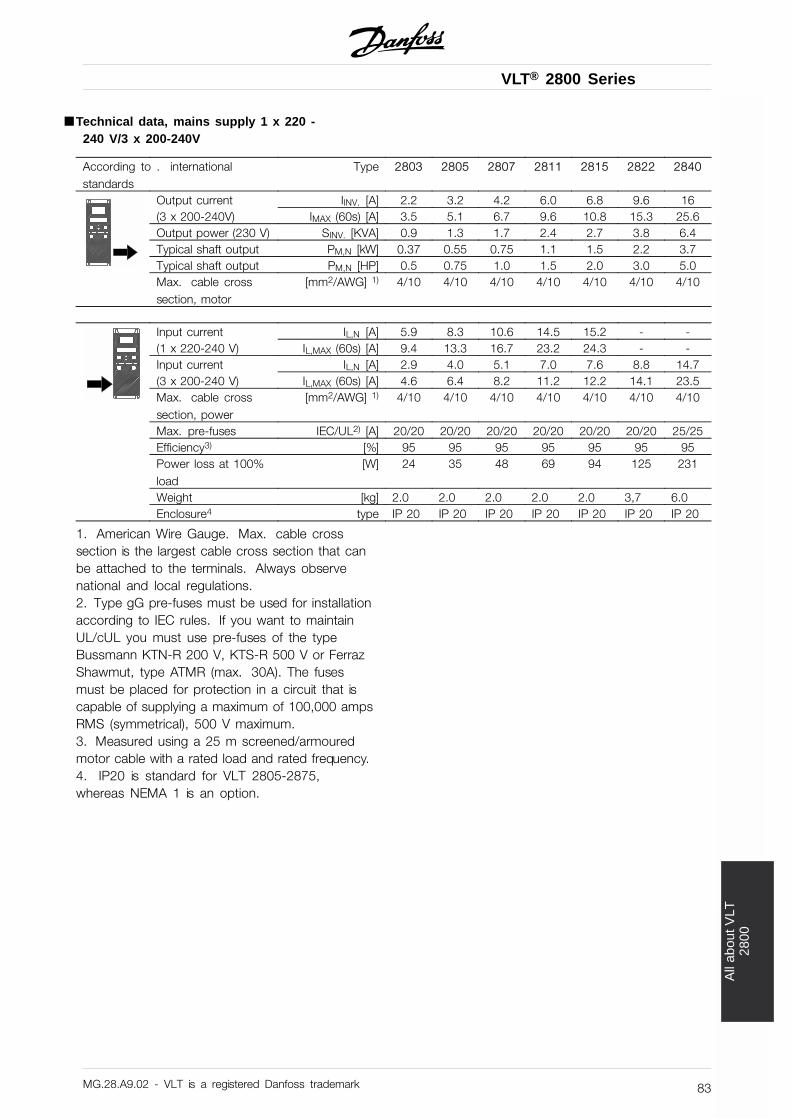
VLT® 2800 Series
All
abou
t VLT
2800
■ Technical data, mains supply 1 x 220 -240 V/3 x 200-240V
According to . internationalstandards
Type 2803 2805 2807 2811 2815 2822 2840
Output current IINV. [A] 2.2 3.2 4.2 6.0 6.8 9.6 16(3 x 200-240V) IMAX (60s) [A] 3.5 5.1 6.7 9.6 10.8 15.3 25.6Output power (230 V) SINV. [KVA] 0.9 1.3 1.7 2.4 2.7 3.8 6.4Typical shaft output PM,N [kW] 0.37 0.55 0.75 1.1 1.5 2.2 3.7Typical shaft output PM,N [HP] 0.5 0.75 1.0 1.5 2.0 3.0 5.0Max. cable crosssection, motor
[mm2/AWG] 1) 4/10 4/10 4/10 4/10 4/10 4/10 4/10
Input current IL,N [A] 5.9 8.3 10.6 14.5 15.2 - -(1 x 220-240 V) IL,MAX (60s) [A] 9.4 13.3 16.7 23.2 24.3 - -Input current IL,N [A] 2.9 4.0 5.1 7.0 7.6 8.8 14.7(3 x 200-240 V) IL,MAX (60s) [A] 4.6 6.4 8.2 11.2 12.2 14.1 23.5Max. cable crosssection, power
[mm2/AWG] 1) 4/10 4/10 4/10 4/10 4/10 4/10 4/10
Max. pre-fuses IEC/UL2) [A] 20/20 20/20 20/20 20/20 20/20 20/20 25/25Efficiency3) [%] 95 95 95 95 95 95 95Power loss at 100%load
[W] 24 35 48 69 94 125 231
Weight [kg] 2.0 2.0 2.0 2.0 2.0 3,7 6.0Enclosure4 type IP 20 IP 20 IP 20 IP 20 IP 20 IP 20 IP 20
1. American Wire Gauge. Max. cable crosssection is the largest cable cross section that canbe attached to the terminals. Always observenational and local regulations.2. Type gG pre-fuses must be used for installationaccording to IEC rules. If you want to maintainUL/cUL you must use pre-fuses of the typeBussmann KTN-R 200 V, KTS-R 500 V or FerrazShawmut, type ATMR (max. 30A). The fusesmust be placed for protection in a circuit that iscapable of supplying a maximum of 100,000 ampsRMS (symmetrical), 500 V maximum.3. Measured using a 25 m screened/armouredmotor cable with a rated load and rated frequency.4. IP20 is standard for VLT 2805-2875,whereas NEMA 1 is an option.
MG.28.A9.02 - VLT is a registered Danfoss trademark 83
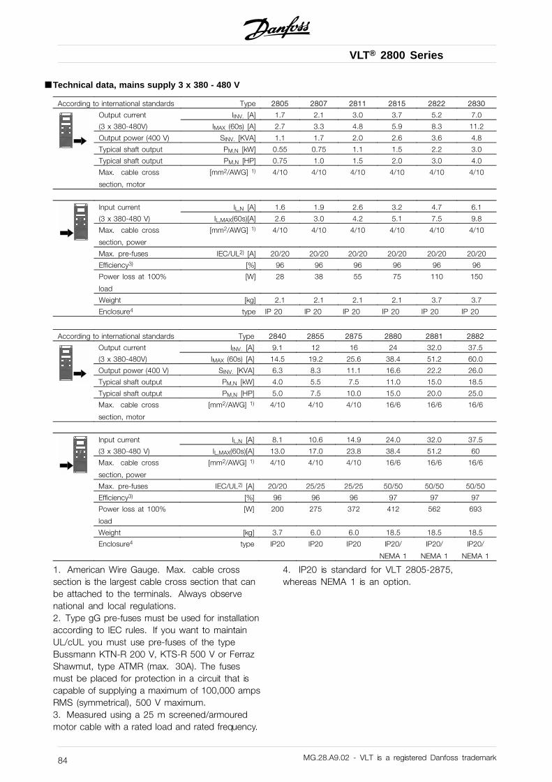
VLT® 2800 Series
■ Technical data, mains supply 3 x 380 - 480 V
According to international standards Type 2805 2807 2811 2815 2822 2830
Output current IINV. [A] 1.7 2.1 3.0 3.7 5.2 7.0
(3 x 380-480V) IMAX (60s) [A] 2.7 3.3 4.8 5.9 8.3 11.2
Output power (400 V) SINV. [KVA] 1.1 1.7 2.0 2.6 3.6 4.8
Typical shaft output PM,N [kW] 0.55 0.75 1.1 1.5 2.2 3.0
Typical shaft output PM,N [HP] 0.75 1.0 1.5 2.0 3.0 4.0
Max. cable cross
section, motor
[mm2/AWG] 1) 4/10 4/10 4/10 4/10 4/10 4/10
Input current IL,N [A] 1.6 1.9 2.6 3.2 4.7 6.1
(3 x 380-480 V) IL,MAX(60s)[A] 2.6 3.0 4.2 5.1 7.5 9.8
Max. cable cross
section, power
[mm2/AWG] 1) 4/10 4/10 4/10 4/10 4/10 4/10
Max. pre-fuses IEC/UL2) [A] 20/20 20/20 20/20 20/20 20/20 20/20
Efficiency3) [%] 96 96 96 96 96 96
Power loss at 100%
load
[W] 28 38 55 75 110 150
Weight [kg] 2.1 2.1 2.1 2.1 3.7 3.7
Enclosure4 type IP 20 IP 20 IP 20 IP 20 IP 20 IP 20
According to international standards Type 2840 2855 2875 2880 2881 2882
Output current IINV. [A] 9.1 12 16 24 32.0 37.5
(3 x 380-480V) IMAX (60s) [A] 14.5 19.2 25.6 38.4 51.2 60.0
Output power (400 V) SINV. [KVA] 6.3 8.3 11.1 16.6 22.2 26.0
Typical shaft output PM,N [kW] 4.0 5.5 7.5 11.0 15.0 18.5
Typical shaft output PM,N [HP] 5.0 7.5 10.0 15.0 20.0 25.0
Max. cable cross
section, motor
[mm2/AWG] 1) 4/10 4/10 4/10 16/6 16/6 16/6
Input current IL,N [A] 8.1 10.6 14.9 24.0 32.0 37.5
(3 x 380-480 V) IL,MAX(60s)[A] 13.0 17.0 23.8 38.4 51.2 60
Max. cable cross
section, power
[mm2/AWG] 1) 4/10 4/10 4/10 16/6 16/6 16/6
Max. pre-fuses IEC/UL2) [A] 20/20 25/25 25/25 50/50 50/50 50/50
Efficiency3) [%] 96 96 96 97 97 97
Power loss at 100%
load
[W] 200 275 372 412 562 693
Weight [kg] 3.7 6.0 6.0 18.5 18.5 18.5
Enclosure4 type IP20 IP20 IP20 IP20/
NEMA 1
IP20/
NEMA 1
IP20/
NEMA 1
1. American Wire Gauge. Max. cable crosssection is the largest cable cross section that canbe attached to the terminals. Always observenational and local regulations.2. Type gG pre-fuses must be used for installationaccording to IEC rules. If you want to maintainUL/cUL you must use pre-fuses of the typeBussmann KTN-R 200 V, KTS-R 500 V or FerrazShawmut, type ATMR (max. 30A). The fusesmust be placed for protection in a circuit that iscapable of supplying a maximum of 100,000 ampsRMS (symmetrical), 500 V maximum.3. Measured using a 25 m screened/armouredmotor cable with a rated load and rated frequency.
4. IP20 is standard for VLT 2805-2875,whereas NEMA 1 is an option.
MG.28.A9.02 - VLT is a registered Danfoss trademark84
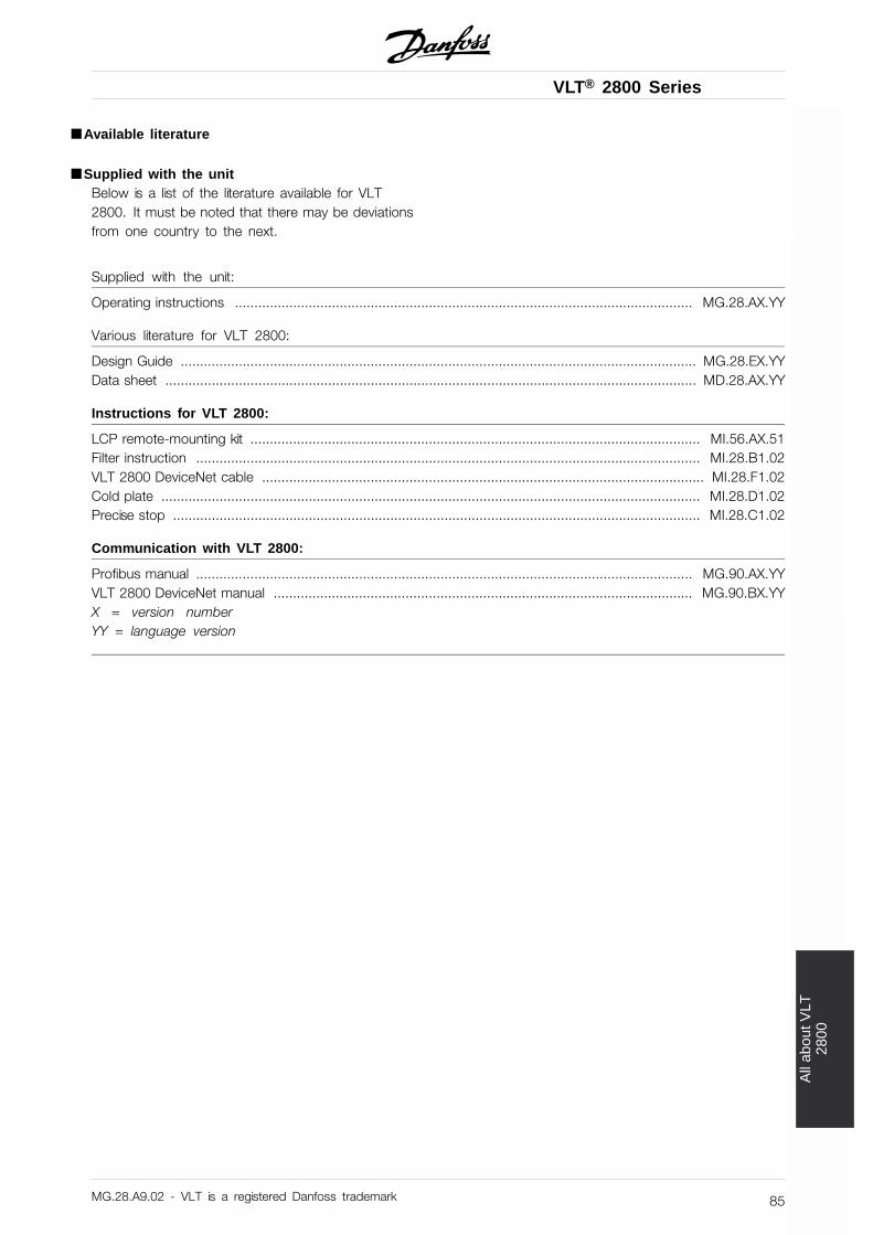
VLT® 2800 Series
All
abou
t VLT
2800
■ Available literature
■ Supplied with the unitBelow is a list of the literature available for VLT2800. It must be noted that there may be deviationsfrom one country to the next.
Supplied with the unit:
Operating instructions ...................................................................................................................... MG.28.AX.YY
Various literature for VLT 2800:
Design Guide ..................................................................................................................................... MG.28.EX.YYData sheet ......................................................................................................................................... MD.28.AX.YY
Instructions for VLT 2800:
LCP remote-mounting kit .................................................................................................................... MI.56.AX.51Filter instruction .................................................................................................................................. MI.28.B1.02VLT 2800 DeviceNet cable .................................................................................................................. MI.28.F1.02Cold plate ........................................................................................................................................... MI.28.D1.02Precise stop ........................................................................................................................................ MI.28.C1.02
Communication with VLT 2800:
Profibus manual ................................................................................................................................ MG.90.AX.YYVLT 2800 DeviceNet manual ............................................................................................................ MG.90.BX.YYX = version numberYY = language version
MG.28.A9.02 - VLT is a registered Danfoss trademark 85
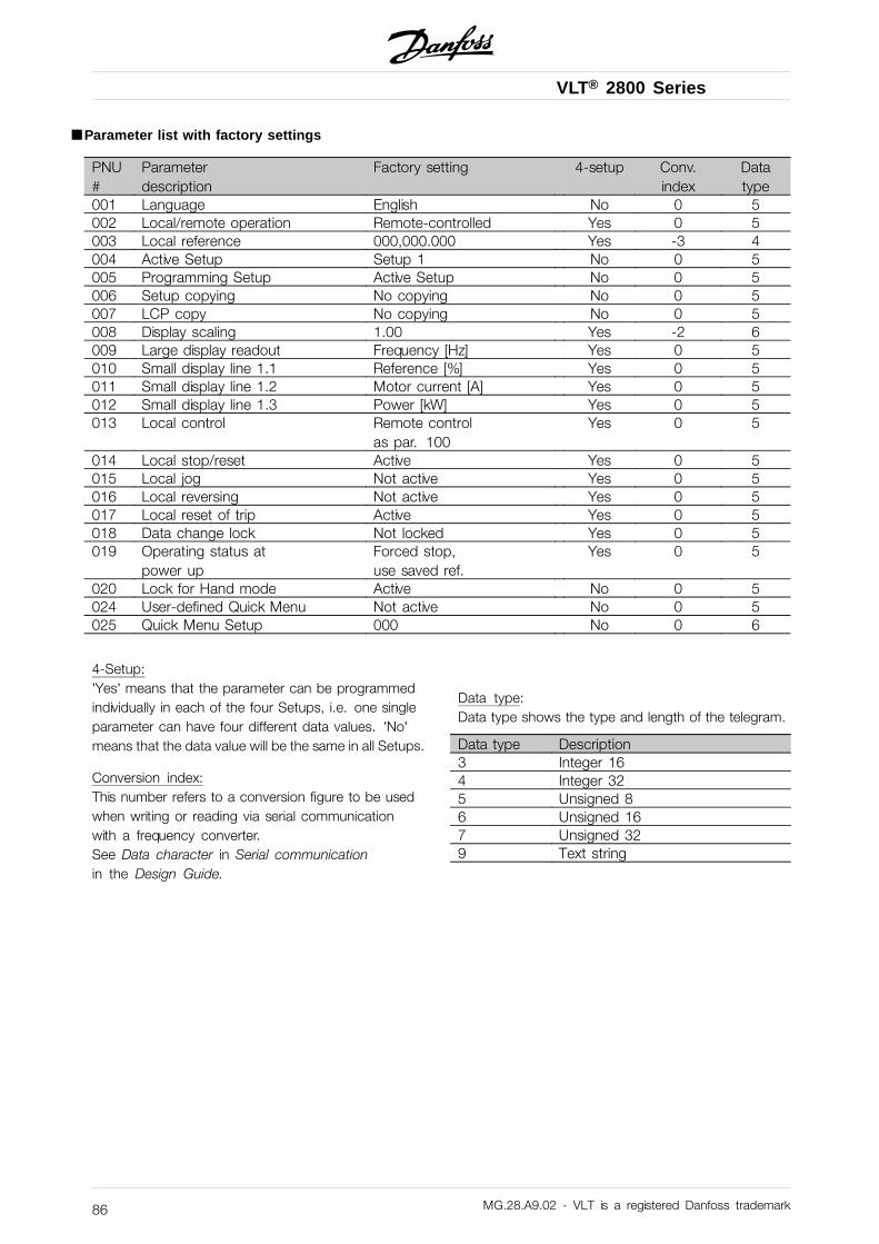
VLT® 2800 Series
■ Parameter list with factory settings
PNU#
Parameterdescription
Factory setting 4-setup Conv.index
Datatype
001 Language English No 0 5002 Local/remote operation Remote-controlled Yes 0 5003 Local reference 000,000.000 Yes -3 4004 Active Setup Setup 1 No 0 5005 Programming Setup Active Setup No 0 5006 Setup copying No copying No 0 5007 LCP copy No copying No 0 5008 Display scaling 1.00 Yes -2 6009 Large display readout Frequency [Hz] Yes 0 5010 Small display line 1.1 Reference [%] Yes 0 5011 Small display line 1.2 Motor current [A] Yes 0 5012 Small display line 1.3 Power [kW] Yes 0 5013 Local control Remote control
as par. 100Yes 0 5
014 Local stop/reset Active Yes 0 5015 Local jog Not active Yes 0 5016 Local reversing Not active Yes 0 5017 Local reset of trip Active Yes 0 5018 Data change lock Not locked Yes 0 5019 Operating status at
power upForced stop,use saved ref.
Yes 0 5
020 Lock for Hand mode Active No 0 5024 User-defined Quick Menu Not active No 0 5025 Quick Menu Setup 000 No 0 6
4-Setup:’Yes’ means that the parameter can be programmedindividually in each of the four Setups, i.e. one singleparameter can have four different data values. ’No’means that the data value will be the same in all Setups.
Conversion index:This number refers to a conversion figure to be usedwhen writing or reading via serial communicationwith a frequency converter.See Data character in Serial communicationin the Design Guide.
Data type:Data type shows the type and length of the telegram.
Data type Description3 Integer 164 Integer 325 Unsigned 86 Unsigned 167 Unsigned 329 Text string
MG.28.A9.02 - VLT is a registered Danfoss trademark86
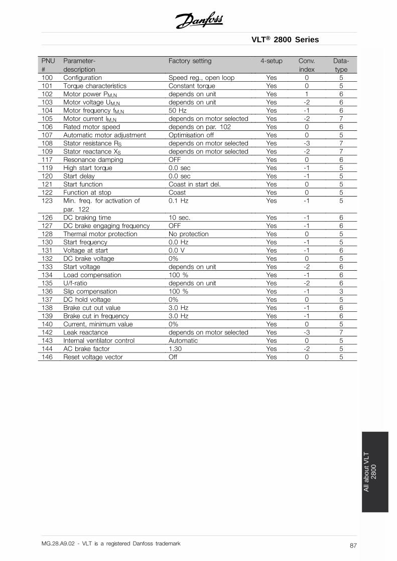
VLT® 2800 Series
All
abou
t VLT
2800
PNU#
Parameter-description
Factory setting 4-setup Conv.index
Data-type
100 Configuration Speed reg., open loop Yes 0 5101 Torque characteristics Constant torque Yes 0 5102 Motor power PM,N depends on unit Yes 1 6103 Motor voltage UM,N depends on unit Yes -2 6104 Motor frequency fM,N 50 Hz Yes -1 6105 Motor current IM,N depends on motor selected Yes -2 7106 Rated motor speed depends on par. 102 Yes 0 6107 Automatic motor adjustment Optimisation off Yes 0 5108 Stator resistance RS depends on motor selected Yes -3 7109 Stator reactance XS depends on motor selected Yes -2 7117 Resonance damping OFF Yes 0 6119 High start torque 0.0 sec Yes -1 5120 Start delay 0.0 sec Yes -1 5121 Start function Coast in start del. Yes 0 5122 Function at stop Coast Yes 0 5123 Min. freq. for activation of
par. 1220.1 Hz Yes -1 5
126 DC braking time 10 sec. Yes -1 6127 DC brake engaging frequency OFF Yes -1 6128 Thermal motor protection No protection Yes 0 5130 Start frequency 0.0 Hz Yes -1 5131 Voltage at start 0.0 V Yes -1 6132 DC brake voltage 0% Yes 0 5133 Start voltage depends on unit Yes -2 6134 Load compensation 100 % Yes -1 6135 U/f-ratio depends on unit Yes -2 6136 Slip compensation 100 % Yes -1 3137 DC hold voltage 0% Yes 0 5138 Brake cut out value 3.0 Hz Yes -1 6139 Brake cut in frequency 3.0 Hz Yes -1 6140 Current, minimum value 0% Yes 0 5142 Leak reactance depends on motor selected Yes -3 7143 Internal ventilator control Automatic Yes 0 5144 AC brake factor 1.30 Yes -2 5146 Reset voltage vector Off Yes 0 5
MG.28.A9.02 - VLT is a registered Danfoss trademark 87
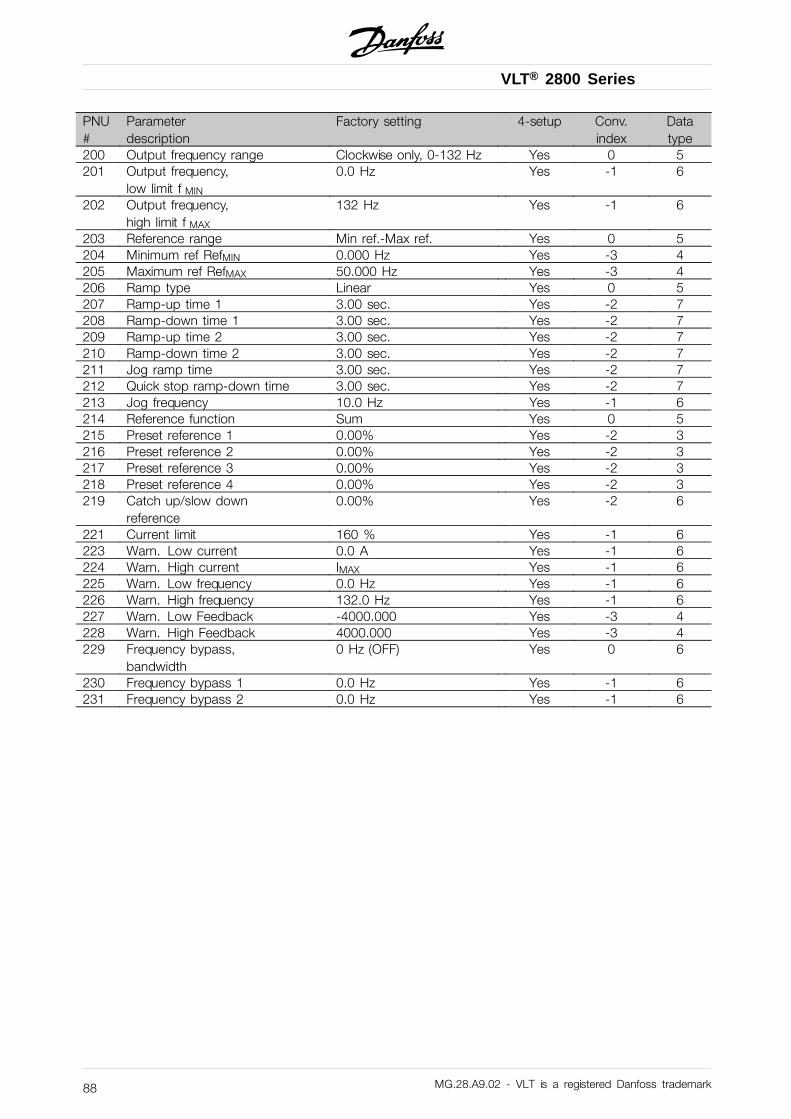
VLT® 2800 Series
PNU#
Parameterdescription
Factory setting 4-setup Conv.index
Datatype
200 Output frequency range Clockwise only, 0-132 Hz Yes 0 5201 Output frequency,
low limit f MIN
0.0 Hz Yes -1 6
202 Output frequency,high limit f MAX
132 Hz Yes -1 6
203 Reference range Min ref.-Max ref. Yes 0 5204 Minimum ref RefMIN 0.000 Hz Yes -3 4205 Maximum ref RefMAX 50.000 Hz Yes -3 4206 Ramp type Linear Yes 0 5207 Ramp-up time 1 3.00 sec. Yes -2 7208 Ramp-down time 1 3.00 sec. Yes -2 7209 Ramp-up time 2 3.00 sec. Yes -2 7210 Ramp-down time 2 3.00 sec. Yes -2 7211 Jog ramp time 3.00 sec. Yes -2 7212 Quick stop ramp-down time 3.00 sec. Yes -2 7213 Jog frequency 10.0 Hz Yes -1 6214 Reference function Sum Yes 0 5215 Preset reference 1 0.00% Yes -2 3216 Preset reference 2 0.00% Yes -2 3217 Preset reference 3 0.00% Yes -2 3218 Preset reference 4 0.00% Yes -2 3219 Catch up/slow down
reference0.00% Yes -2 6
221 Current limit 160 % Yes -1 6223 Warn. Low current 0.0 A Yes -1 6224 Warn. High current IMAX Yes -1 6225 Warn. Low frequency 0.0 Hz Yes -1 6226 Warn. High frequency 132.0 Hz Yes -1 6227 Warn. Low Feedback -4000.000 Yes -3 4228 Warn. High Feedback 4000.000 Yes -3 4229 Frequency bypass,
bandwidth0 Hz (OFF) Yes 0 6
230 Frequency bypass 1 0.0 Hz Yes -1 6231 Frequency bypass 2 0.0 Hz Yes -1 6
MG.28.A9.02 - VLT is a registered Danfoss trademark88
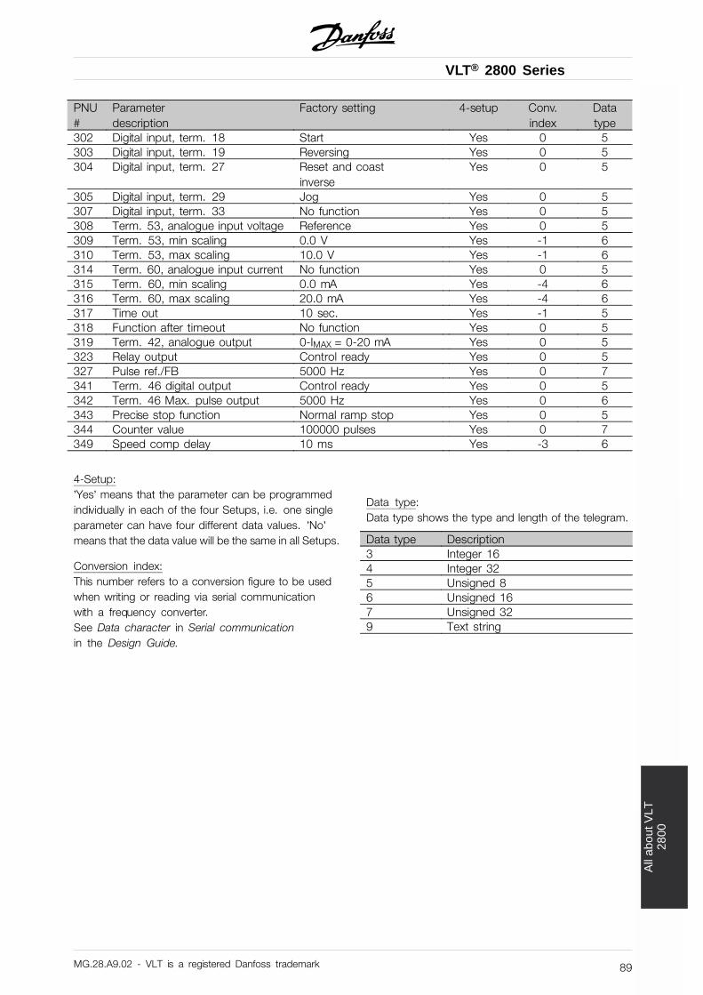
VLT® 2800 Series
All
abou
t VLT
2800
PNU#
Parameterdescription
Factory setting 4-setup Conv.index
Datatype
302 Digital input, term. 18 Start Yes 0 5303 Digital input, term. 19 Reversing Yes 0 5304 Digital input, term. 27 Reset and coast
inverseYes 0 5
305 Digital input, term. 29 Jog Yes 0 5307 Digital input, term. 33 No function Yes 0 5308 Term. 53, analogue input voltage Reference Yes 0 5309 Term. 53, min scaling 0.0 V Yes -1 6310 Term. 53, max scaling 10.0 V Yes -1 6314 Term. 60, analogue input current No function Yes 0 5315 Term. 60, min scaling 0.0 mA Yes -4 6316 Term. 60, max scaling 20.0 mA Yes -4 6317 Time out 10 sec. Yes -1 5318 Function after timeout No function Yes 0 5319 Term. 42, analogue output 0-IMAX = 0-20 mA Yes 0 5323 Relay output Control ready Yes 0 5327 Pulse ref./FB 5000 Hz Yes 0 7341 Term. 46 digital output Control ready Yes 0 5342 Term. 46 Max. pulse output 5000 Hz Yes 0 6343 Precise stop function Normal ramp stop Yes 0 5344 Counter value 100000 pulses Yes 0 7349 Speed comp delay 10 ms Yes -3 6
4-Setup:’Yes’ means that the parameter can be programmedindividually in each of the four Setups, i.e. one singleparameter can have four different data values. ’No’means that the data value will be the same in all Setups.
Conversion index:This number refers to a conversion figure to be usedwhen writing or reading via serial communicationwith a frequency converter.See Data character in Serial communicationin the Design Guide.
Data type:Data type shows the type and length of the telegram.
Data type Description3 Integer 164 Integer 325 Unsigned 86 Unsigned 167 Unsigned 329 Text string
MG.28.A9.02 - VLT is a registered Danfoss trademark 89
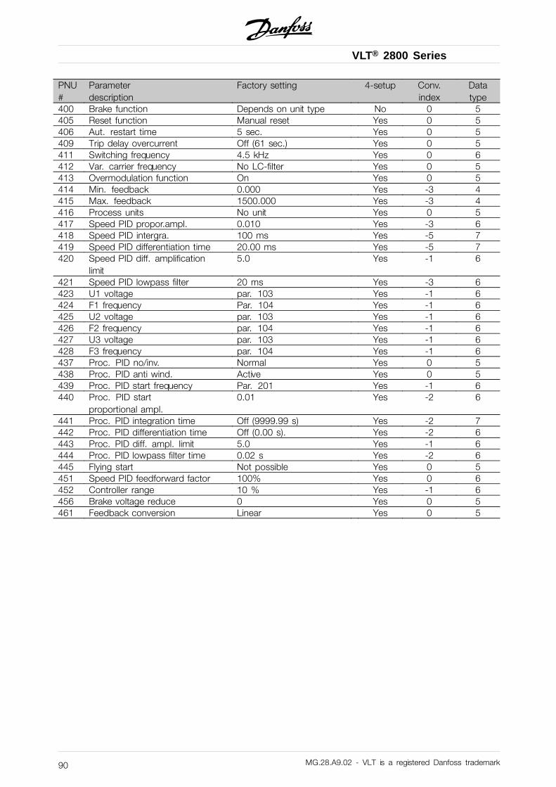
VLT® 2800 Series
PNU#
Parameterdescription
Factory setting 4-setup Conv.index
Datatype
400 Brake function Depends on unit type No 0 5405 Reset function Manual reset Yes 0 5406 Aut. restart time 5 sec. Yes 0 5409 Trip delay overcurrent Off (61 sec.) Yes 0 5411 Switching frequency 4.5 kHz Yes 0 6412 Var. carrier frequency No LC-filter Yes 0 5413 Overmodulation function On Yes 0 5414 Min. feedback 0.000 Yes -3 4415 Max. feedback 1500.000 Yes -3 4416 Process units No unit Yes 0 5417 Speed PID propor.ampl. 0.010 Yes -3 6418 Speed PID intergra. 100 ms Yes -5 7419 Speed PID differentiation time 20.00 ms Yes -5 7420 Speed PID diff. amplification
limit5.0 Yes -1 6
421 Speed PID lowpass filter 20 ms Yes -3 6423 U1 voltage par. 103 Yes -1 6424 F1 frequency Par. 104 Yes -1 6425 U2 voltage par. 103 Yes -1 6426 F2 frequency par. 104 Yes -1 6427 U3 voltage par. 103 Yes -1 6428 F3 frequency par. 104 Yes -1 6437 Proc. PID no/inv. Normal Yes 0 5438 Proc. PID anti wind. Active Yes 0 5439 Proc. PID start frequency Par. 201 Yes -1 6440 Proc. PID start
proportional ampl.0.01 Yes -2 6
441 Proc. PID integration time Off (9999.99 s) Yes -2 7442 Proc. PID differentiation time Off (0.00 s). Yes -2 6443 Proc. PID diff. ampl. limit 5.0 Yes -1 6444 Proc. PID lowpass filter time 0.02 s Yes -2 6445 Flying start Not possible Yes 0 5451 Speed PID feedforward factor 100% Yes 0 6452 Controller range 10 % Yes -1 6456 Brake voltage reduce 0 Yes 0 5461 Feedback conversion Linear Yes 0 5
MG.28.A9.02 - VLT is a registered Danfoss trademark90
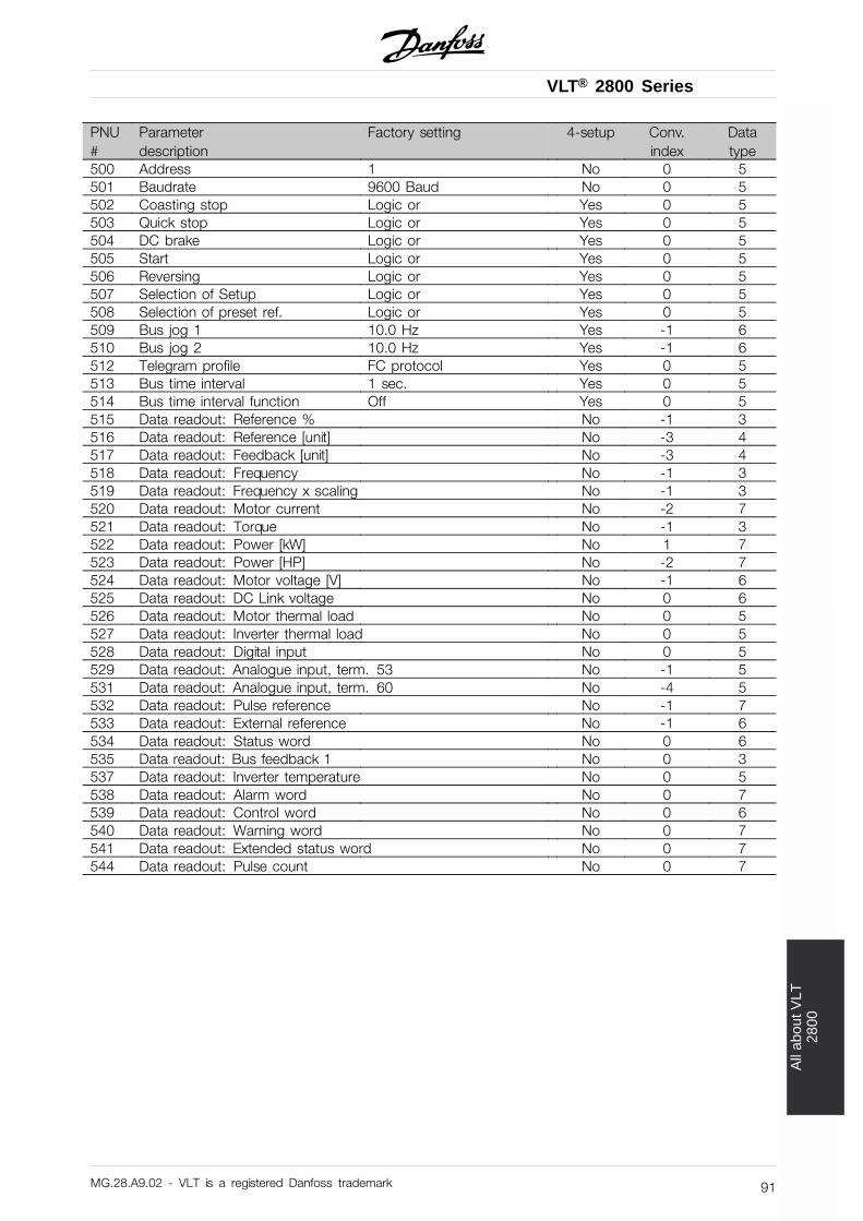
VLT® 2800 Series
All
abou
t VLT
2800
PNU#
Parameterdescription
Factory setting 4-setup Conv.index
Datatype
500 Address 1 No 0 5501 Baudrate 9600 Baud No 0 5502 Coasting stop Logic or Yes 0 5503 Quick stop Logic or Yes 0 5504 DC brake Logic or Yes 0 5505 Start Logic or Yes 0 5506 Reversing Logic or Yes 0 5507 Selection of Setup Logic or Yes 0 5508 Selection of preset ref. Logic or Yes 0 5509 Bus jog 1 10.0 Hz Yes -1 6510 Bus jog 2 10.0 Hz Yes -1 6512 Telegram profile FC protocol Yes 0 5513 Bus time interval 1 sec. Yes 0 5514 Bus time interval function Off Yes 0 5515 Data readout: Reference % No -1 3516 Data readout: Reference [unit] No -3 4517 Data readout: Feedback [unit] No -3 4518 Data readout: Frequency No -1 3519 Data readout: Frequency x scaling No -1 3520 Data readout: Motor current No -2 7521 Data readout: Torque No -1 3522 Data readout: Power [kW] No 1 7523 Data readout: Power [HP] No -2 7524 Data readout: Motor voltage [V] No -1 6525 Data readout: DC Link voltage No 0 6526 Data readout: Motor thermal load No 0 5527 Data readout: Inverter thermal load No 0 5528 Data readout: Digital input No 0 5529 Data readout: Analogue input, term. 53 No -1 5531 Data readout: Analogue input, term. 60 No -4 5532 Data readout: Pulse reference No -1 7533 Data readout: External reference No -1 6534 Data readout: Status word No 0 6535 Data readout: Bus feedback 1 No 0 3537 Data readout: Inverter temperature No 0 5538 Data readout: Alarm word No 0 7539 Data readout: Control word No 0 6540 Data readout: Warning word No 0 7541 Data readout: Extended status word No 0 7544 Data readout: Pulse count No 0 7
MG.28.A9.02 - VLT is a registered Danfoss trademark 91
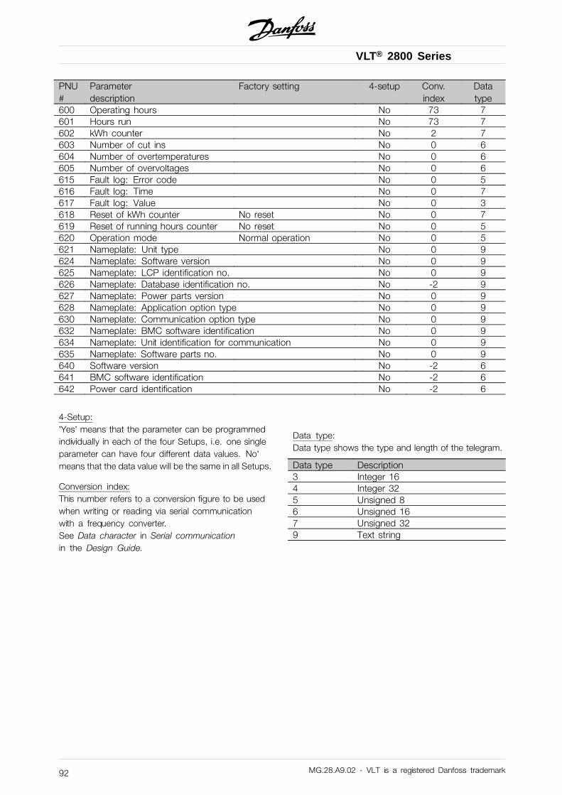
VLT® 2800 Series
PNU#
Parameterdescription
Factory setting 4-setup Conv.index
Datatype
600 Operating hours No 73 7601 Hours run No 73 7602 kWh counter No 2 7603 Number of cut ins No 0 6604 Number of overtemperatures No 0 6605 Number of overvoltages No 0 6615 Fault log: Error code No 0 5616 Fault log: Time No 0 7617 Fault log: Value No 0 3618 Reset of kWh counter No reset No 0 7619 Reset of running hours counter No reset No 0 5620 Operation mode Normal operation No 0 5621 Nameplate: Unit type No 0 9624 Nameplate: Software version No 0 9625 Nameplate: LCP identification no. No 0 9626 Nameplate: Database identification no. No -2 9627 Nameplate: Power parts version No 0 9628 Nameplate: Application option type No 0 9630 Nameplate: Communication option type No 0 9632 Nameplate: BMC software identification No 0 9634 Nameplate: Unit identification for communication No 0 9635 Nameplate: Software parts no. No 0 9640 Software version No -2 6641 BMC software identification No -2 6642 Power card identification No -2 6
4-Setup:’Yes’ means that the parameter can be programmedindividually in each of the four Setups, i.e. one singleparameter can have four different data values. No’means that the data value will be the same in all Setups.
Conversion index:This number refers to a conversion figure to be usedwhen writing or reading via serial communicationwith a frequency converter.See Data character in Serial communicationin the Design Guide.
Data type:Data type shows the type and length of the telegram.
Data type Description3 Integer 164 Integer 325 Unsigned 86 Unsigned 167 Unsigned 329 Text string
MG.28.A9.02 - VLT is a registered Danfoss trademark92
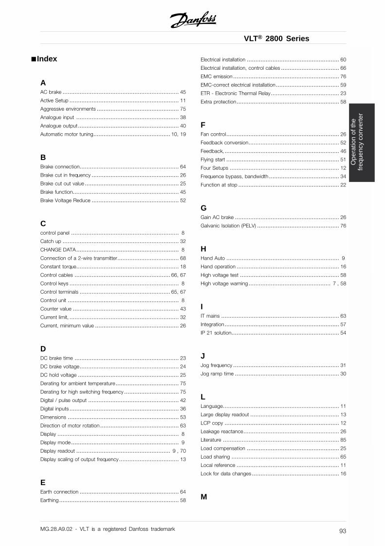
VLT® 2800 Series
Ope
ratio
n of
the
freq
uenc
y co
nver
ter
■ Index
AAC brake .................................................................... 45
Active Setup ................................................................ 11
Aggressive environments ................................................ 75
Analogue input ............................................................ 38
Analogue output........................................................... 40
Automatic motor tuning............................................. 10, 19
BBrake connection.......................................................... 64
Brake cut in frequency ................................................... 26
Brake cut out value ....................................................... 25
Brake function.............................................................. 45
Brake Voltage Reduce ................................................... 52
Ccontrol panel ............................................................... 8
Catch up .................................................................... 32
CHANGE DATA............................................................ 8
Connection of a 2-wire transmitter.................................... 68
Constant torque............................................................ 18
Control cables ........................................................ 66, 67
Control keys ................................................................ 8
Control terminals ..................................................... 65, 67
Control unit ................................................................. 8
Counter value .............................................................. 43
Current limit, ................................................................ 32
Current, minimum value ................................................. 26
DDC brake time ............................................................. 23
DC brake voltage.......................................................... 24
DC hold voltage ........................................................... 25
Derating for ambient temperature..................................... 75
Derating for high switching frequency ................................ 75
Digital / pulse output ..................................................... 42
Digital inputs ................................................................ 36
Dimensions ................................................................. 53
Direction of motor rotation .............................................. 63
Display ....................................................................... 8
Display mode............................................................... 9
Display readout ....................................................... 9 , 70
Display scaling of output frequency................................... 13
EEarth connection .......................................................... 64
Earthing...................................................................... 58
Electrical installation ...................................................... 60
Electrical installation, control cables .................................. 66
EMC emission .............................................................. 76
EMC-correct electrical installation..................................... 59
ETR - Electronic Thermal Relay........................................ 23
Extra protection............................................................ 58
FFan control.................................................................. 26
Feedback conversion..................................................... 52
Feedback, ................................................................... 46
Flying start .................................................................. 51
Four Setups ................................................................ 12
Frequence bypass, bandwidth ......................................... 34
Function at stop ........................................................... 22
GGain AC brake ............................................................. 26
Galvanic Isolation (PELV) ................................................ 76
HHand Auto .................................................................. 9
Hand operation ............................................................ 16
High voltage test .......................................................... 58
High voltage warning ................................................ 7 , 58
IIT mains ..................................................................... 63
Integration................................................................... 57
IP 21 solution............................................................... 54
JJog frequency .............................................................. 31
Jog ramp time ............................................................. 30
LLanguage.................................................................... 11
Large display readout .................................................... 13
LCP copy ................................................................... 12
Leakage reactance........................................................ 26
Literature .................................................................... 85
Load compensation ...................................................... 25
Load sharing ............................................................... 65
Local reference ............................................................ 11
Lock for data changes ................................................... 16
M
MG.28.A9.02 - VLT is a registered Danfoss trademark 93
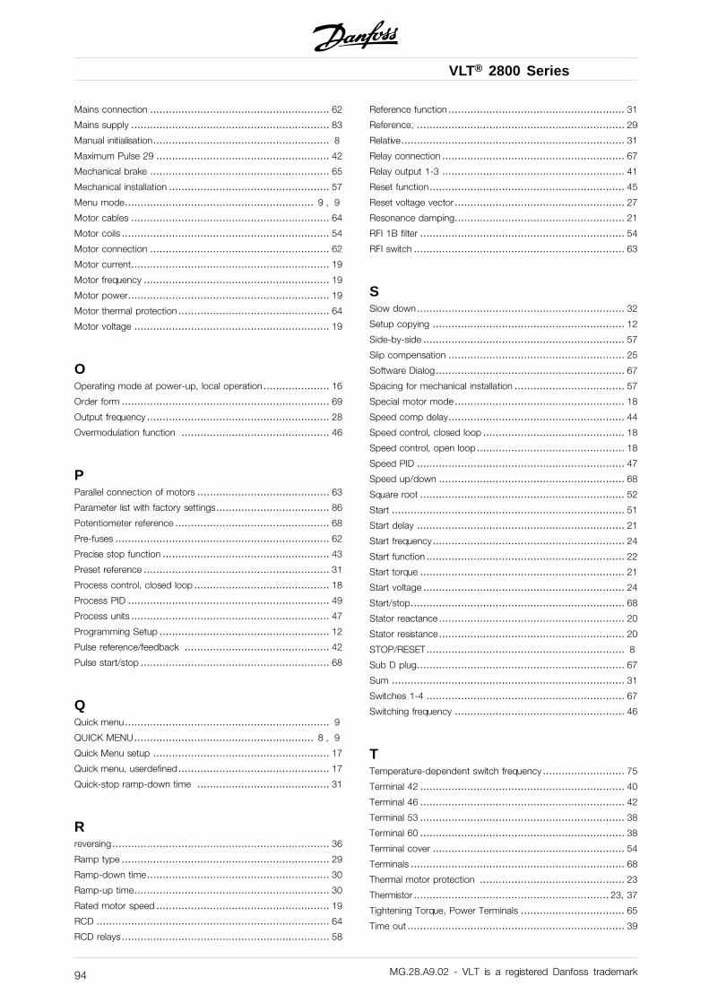
VLT® 2800 Series
Mains connection ......................................................... 62
Mains supply ............................................................... 83
Manual initialisation........................................................ 8
Maximum Pulse 29 ....................................................... 42
Mechanical brake ......................................................... 65
Mechanical installation ................................................... 57
Menu mode............................................................ 9 , 9
Motor cables ............................................................... 64
Motor coils .................................................................. 54
Motor connection ......................................................... 62
Motor current............................................................... 19
Motor frequency ........................................................... 19
Motor power................................................................ 19
Motor thermal protection ................................................ 64
Motor voltage .............................................................. 19
OOperating mode at power-up, local operation..................... 16
Order form .................................................................. 69
Output frequency .......................................................... 28
Overmodulation function ............................................... 46
PParallel connection of motors .......................................... 63
Parameter list with factory settings.................................... 86
Potentiometer reference ................................................. 68
Pre-fuses .................................................................... 62
Precise stop function ..................................................... 43
Preset reference ........................................................... 31
Process control, closed loop ........................................... 18
Process PID ................................................................ 49
Process units ............................................................... 47
Programming Setup ...................................................... 12
Pulse reference/feedback .............................................. 42
Pulse start/stop ............................................................ 68
QQuick menu................................................................. 9
QUICK MENU......................................................... 8 , 9
Quick Menu setup ........................................................ 17
Quick menu, userdefined................................................ 17
Quick-stop ramp-down time .......................................... 31
Rreversing..................................................................... 36
Ramp type .................................................................. 29
Ramp-down time.......................................................... 30
Ramp-up time.............................................................. 30
Rated motor speed ....................................................... 19
RCD .......................................................................... 64
RCD relays.................................................................. 58
Reference function ........................................................ 31
Reference, .................................................................. 29
Relative....................................................................... 31
Relay connection .......................................................... 67
Relay output 1-3 .......................................................... 41
Reset function.............................................................. 45
Reset voltage vector...................................................... 27
Resonance damping...................................................... 21
RFI 1B filter ................................................................. 54
RFI switch ................................................................... 63
SSlow down.................................................................. 32
Setup copying ............................................................. 12
Side-by-side ................................................................ 57
Slip compensation ........................................................ 25
Software Dialog............................................................ 67
Spacing for mechanical installation ................................... 57
Special motor mode...................................................... 18
Speed comp delay........................................................ 44
Speed control, closed loop ............................................. 18
Speed control, open loop............................................... 18
Speed PID .................................................................. 47
Speed up/down ........................................................... 68
Square root ................................................................. 52
Start .......................................................................... 51
Start delay .................................................................. 21
Start frequency............................................................. 24
Start function ............................................................... 22
Start torque ................................................................. 21
Start voltage ................................................................ 24
Start/stop.................................................................... 68
Stator reactance........................................................... 20
Stator resistance........................................................... 20
STOP/RESET............................................................... 8
Sub D plug.................................................................. 67
Sum .......................................................................... 31
Switches 1-4 ............................................................... 67
Switching frequency ...................................................... 46
TTemperature-dependent switch frequency .......................... 75
Terminal 42 ................................................................. 40
Terminal 46 ................................................................. 42
Terminal 53 ................................................................. 38
Terminal 60 ................................................................. 38
Terminal cover ............................................................. 54
Terminals .................................................................... 68
Thermal motor protection .............................................. 23
Thermistor .............................................................. 23, 37
Tightening Torque, Power Terminals ................................. 65
Time out ..................................................................... 39
MG.28.A9.02 - VLT is a registered Danfoss trademark94
VLT® 2800 Series
Ope
ratio
n of
the
freq
uenc
y co
nver
ter
Torque characteristic .................................................... 18
UU/f-ratio...................................................................... 25
UL Standard................................................................ 78
VVariable torque ............................................................. 18
WWarning functions ........................................................ 32
Warning words, extended status words and Alarmwords ..... 74
Warnings/alarm messages .............................................. 70
MG.28.A9.02 - VLT is a registered Danfoss trademark 95