VLT 6000 HVAC - Приводная техника Danfoss ... · PDF fileVLT® 6000 HVAC...
27
VLT ® 6000 HVAC 1 MG.60.G2.02 - VLT is a registered Danfoss Trademark ■ Contents Introduction Safety ....................................................................... 3 Safety Guidelines ........................................................ 3 Warnings Against Unintended Start ............................... 3 Introduction ............................................................... 4 About this manual .......................................................4 Assumptions.............................................................. 4 References................................................................ 4 Trademarks ............................................................... 5 Programming the VLT 6000 Control Panel ............................................................. 5 Parameter Change Keys ............................................. 5 Local Control ............................................................. 6 Quick Menu .............................................................. 6 To Enter or Change Quick Menu Parameter Data ........... 7 Example of Changing Parameter Data........................... 7 Extended Menu.......................................................... 8 HP/kW ...................................................................... 8 VLT 6000 Functional Features Drive Operation .......................................................... 8 Motor and Drive Thermal Protection ............................. 8 Set-up 1-4................................................................. 8 Current Monitoring and Limits ....................................... 9 Direction of Rotation ................................................... 9 Start/Stop.................................................................. 9 Freeze Mode ............................................................. 9 Coast........................................................................ 9 Motor Ramp-up and Ramp-down Rate ......................... 9 Lock Panel ................................................................ 9 Hand/Auto Modes....................................................... 9 Run Enable................................................................ 9 Bus Functions............................................................ 9 Frequency Out High, Low Limits ................................... 9 Relay Out 1,2 ........................................................... 9 PID Control Functions................................................ 10 Sleep Mode ............................................................. 10 Drive Control Display ................................................. 10 Terminals ................................................................. 10 Faults, Warnings and Alarms ...................................... 10 Error Status ............................................................. 10 VLT 6000 Network Strategies Strategy One ........................................................... 11 Strategy Two........................................................... 11 Strategy Three ......................................................... 13 Strategy Four ........................................................... 13
-
Upload
hoangtuyen -
Category
Documents
-
view
256 -
download
6
Transcript of VLT 6000 HVAC - Приводная техника Danfoss ... · PDF fileVLT® 6000 HVAC...
VLT® 6000 HVAC
1MG.60.G2.02 - VLT is a registered Danfoss Trademark
■■■■■ Contents
IntroductionSafety .......................................................................3Safety Guidelines ........................................................3Warnings Against Unintended Start ...............................3Introduction ...............................................................4About this manual.......................................................4Assumptions..................................... .........................4References................................................................4Trademarks ...............................................................5
Programming the VLT 6000Control Panel .............................................................5Parameter Change Keys .............................................5Local Control .............................................................6Quick Menu ..............................................................6To Enter or Change Quick Menu Parameter Data ...........7Example of Changing Parameter Data...........................7Extended Menu..........................................................8HP/kW......................................................................8
VLT 6000 Functional FeaturesDrive Operation ..........................................................8Motor and Drive Thermal Protection .............................8Set-up 1-4.................................................................8Current Monitoring and Limits.......................................9Direction of Rotation ...................................................9Start/Stop..................................................................9Freeze Mode .............................................................9Coast........................................................................9Motor Ramp-up and Ramp-down Rate .........................9Lock Panel ................................................................9Hand/Auto Modes.......................................................9Run Enable................................................................9Bus Functions............................................................9Frequency Out High, Low Limits...................................9Relay Out 1,2 ...........................................................9PID Control Functions................................................10Sleep Mode .............................................................10Drive Control Display .................................................10Terminals .................................................................10Faults, Warnings and Alarms ......................................10Error Status .............................................................10
VLT 6000 Network StrategiesStrategy One ...........................................................11Strategy Two........................................................... 11Strategy Three .........................................................13Strategy Four ...........................................................13
VLT® 6000 HVAC
2 MG.60.G2.02 - VLT is a registered Danfoss Trademark
VLT 6000 Special FunctionsSafety Interlock ...........................................................15Analog Input Monitoring ...............................................15Drive Relay Control 15
Network ConnectionHardware Setup ..........................................................16Electrical Control Terminals............................................17Typical Control Connection Examples..............................18
VLT 6000 Functional FeaturesStartup of FLN Manual .................................................20Faults, Warnings and Alarms .........................................20Point Mapping Table .....................................................22Point Mapping Table Notes............................................25Point Database Definitions.............................................26

VLT® 6000 HVAC
3MG.60.G2.02 - VLT is a registered Danfoss Trademark
Rotating shafts and electrical equipmentcan be hazardous. Therefore, it is stronglyrecommended that all electrical work con-
form to National Electrical Code (NEC) and all localregulations. Installation, start-up and maintenanceshould be performed only by qualified personnel.
Factory recommended procedures, included in thismanual, should be followed. Always disconnectelectrical power before working on the unit.Although shaft couplings or belt drives are generallynot furnished by the manufacturer, rotating shafts,couplings and belts must be protected with securelymounted metal guards that are of sufficient thicknessto provide protection against flying particles such askeys, bolts and coupling parts. Even when the motoris stopped, it should be considered “alive” as long asits controller is energized. Automatic circuits maystart the motor at any time. Keep hands away fromthe output shaft until the motor has completelystopped and power is disconnected from thecontroller.Motor control equipment and electronic controls areconnected to hazardous line voltages. Whenservicing drives and electronic controls, there will beexposed components at or above line potential.Extreme care should be taken to protect againstshock. Stand on an insulating pad and make it ahabit to use only one hand when checking compo-nents. Always work with another person in case ofan emergency. Disconnect power whenever pos-sible to check controls or to perform maintenance.Be sure equipment is properly grounded. Wear safetyglasses whenever working on electric control orrotating equipment.
Safety Guidelines1. The drive must be disconnected from the AC
line before any service work is done.
2. The “Stop/Off” key on the local control panelof the drive does not disconnect the equip-ment from the AC line and is not to be usedas a safety switch.
■■■■■ Safety 3. Correct protective grounding of the equipmentmust be established. The user must be protec-ted against supply voltage and the motor mustbe protected against overload in accordancewith applicable national and local regulations.
4. Ground currents are higher than 3 mA.
Warnings Against Unintended Start1. While the drive is connected to the AC line, the
motor can be brought to a stop by means ofexternal switch closures, serial bus commandsor references. If personal safety considerationsmake it necessary to ensure that no unin-tended start occurs, these stops are notsufficient.
2. During programming of parameters, the motormay start. Be certain that no one is in the areaof the motor or driven equipment whenchanging parameters.
3. A motor that has been stopped may startunexpectedly if faults occur in the electronicsof the drive, or if an overload, a fault in thesupply AC line or a fault in the motorconnection or other fault clears.
4. If the “Local/Hand” key is activated, the motorcan only be brought to a stop by means of the“Stop/Off” key or an external safety interlock
NOTE:NOTE:NOTE:NOTE:NOTE:It is responsibility of user or person installingdrive to provide proper grounding and branch
circuit protection for incoming power and motoroverload according to National Electrical Code (NEC)and local codes.
The Electronic Thermal Relay (ETR) in UL listedVLTs provides Class 20 motor overload protectionin accordance with NEC in single motor applica-tions, when parameter 117 is set for ETR TRIP 1,ETR TRIP 2, ETR TRIP 3, or ETR TRIP 4, andparameter 105 is set for rated motor(nameplate) current.

VLT® 6000 HVAC
4 MG.60.G2.02 - VLT is a registered Danfoss Trademark
About This ManualThe documentation in this manual providescomprehensive information on the connection,programming, and start-up of the VLT 6000 foruse with the FLN. It is intended as both an instruc-tion and reference manual. Functions and featuresof the VLT 6000 frequency converter are alsobriefly reviewed to serve as a guideline to optimizeyour communication system. Read this manualbefore programming since important information isprovided in each section.For detailed information on using the VLT 6000, seethe VLT 6000 Operating Instructions.
AssumptionsThis manual assumes that the controller nodesupports the interfaces in this document and thatall the requirements and limitations stipulated in thecontroller node and the VLT 6000 are strictly ob-served. It is assumed that the user understandsthe general capabilities and limitation of the con-troller node and the VLT 6000 Frequency Converter.
ReferencesInstallation, Operation and Maintenance Manualfor the VLT 6000 Frequency Converter,Danfoss Graham document 23-6108-00.(Referred to as the VLT 6000 Operating Instructionsin this manual.)Operating Instructions VLT 6000 HVAC FrequencyConverter, Danfoss document MG.60.AX.YY(International version of the VLT 6000 OperatingInstructions.)Contact Siemens for operational instructions for theFloor Level Network.
■ ■ ■ ■ ■ Introduction
Touching electrical parts may be fatal - even after equipmenthas been disconnected from AC line. To be sure thatcapacitors have fully discharged, wait 14 minutes for 220and 500 V units and 30 minutes for 550-600 V units afterpower has been removed before touching any internalcomponent.
DANGER:
The Siemens Floor Level Network (FLN) is a master/slave control network for serial communication withvarious control devices. The FLN controller is RS-485 compatible, half duplex, with an operating rateof 4800 or 9600 baud. Recommended wiring isshielded, twisted pair. The FLN software protocol isdesigned to be general in nature to accommodateany unique properties of each device type. The nodeaddress system allows up to 96 devices to be usedon any one system.
The Danfoss VLT 6000 is a programmable frequencyconverter which controls the operation of 3-phase,standard induction electrical motors in the HVACindustry. The VLT 6000 controller has FLNcommunication protocol software built-in. The driveuses optical isolation for fault tolerance and noiseimmunity.
The FLN communicates directly with the VLT 6000drive via the RS-485 serial interface bus. In additionto being able to control the drive, most drive confi-guration and control parameters can be reviewedand changed through the FLN. Also, the operatio-nal status of the drive can be read and monitoredthrough the bus. Diagnostic and operational infor-mation stored in the VLT 6000 is easily available,such as kWh of energy used, total operation hours,drive status, motor speed, and many other usefulitems which can be accessed and monitoredthrough the FLN.
The FLN is designed to communicate with anycontroller node that supports the interfaces definedin this document.

VLT® 6000 HVAC
5MG.60.G2.02 - VLT is a registered Danfoss Trademark
■■■■■ Programming the VLT 6000
Parameter Change KeysThe LCP keys are divided into groups by function.The keys above indicator lamps are used forparameter setup, selecting the display indicationduring normal operation, and controlling the drivespeed during local speed control operation.The keys below the indicator lamps are used forStart/Stop control, selection of the operatinglocation, and reset.
FigurFigurFigurFigurFigure 1 e 1 e 1 e 1 e 1 VLT 6000 Keypad
The DISPLAY MODE key is used tochange a display mode or to returnto the Display Mode from either theQuick Menu or the Extend Menumode.
The QUICK MENU key gives accessto the parameters available for theQuick Menu setup. Parameters inthis menu are the 12 most importantsetup parameters for the drive.
The EXTEND.MENU key givesaccess to all parameters.
The CHANGE DATA key is used forchanging the value of a selectedparameter. To change data, thedesired parameter is first selected. TheCHANGE DATA key is then pressed toenable editing of the parameter. Anunderline in the display will move underthe parameter‘s value to show that it isbeing edited.
TrademarksFLN® is a Siemens registered trademark.VLT® is a Danfoss registered trademark.
The VLT 6000 frequency converter is delivered forinstallation and setup with the required applica-tionparameters already programmed at the factory.Specific motor nameplate data may have to beentered at the time of setup. The instructions in thissection are intended to provide a general under-standing of programming procedures and to enterQuick Menu setup data. See the VLT 6000Operating Instructions for detailed information.
NOTE:NOTE:NOTE:NOTE:NOTE:Quick menu data for commissioning drivecannot be entered via FLN serial bus.
Control PanelThe Local Control Panel (LCP), see Figure 1, is acomplete interface for programming and operatingthe drive. The control panel can be removed fromthe drive and installed up to 3 meters (10 feet) awayusing the remote mounting kit.
The control panel has five functions:
- Display- Keys for changing the display- Keys for changing programming parameters- Keys for controlling drive operation- Indicator lamps
The LCP uses a four-line, alpha-numeric LCDdisplay. The display can show four operating datavalues and three operating condition valuescontinuously. During programming, all the informationrequired for quick, effective parameter setup of thedrive is displayed. All drive parameters can bechanged from the control panel. Three lamps indicatepower on (ON), warning (WARNING) andalarm (ALARM).

VLT® 6000 HVAC
6 MG.60.G2.02 - VLT is a registered Danfoss Trademark
The CANCEL key is used if a change ofthe selected parameter is not to becarried out.
The OK key is used to activate achange to the selected parameter.
The + and - keys are used to scrollthrough parameters and to increase ordecrease the value of a chosenparameter. The keys are also used tochange the local reference. In DisplayMode, the keys are used to switchbetween readouts.
The � and � keys are used to select aparameter group and also to move thecursor to the desired digit whenchanging numerical values.
Local Control
Start signal via digital inputs may causedrive to start at any time. Remove powerto drive before working on output wiring,
motor or any driven equipment.
Below the indicator lamps on the LCP are keysused to determine control of the drive. Each key canbe individually enabled or disabled using parameters012 through 015. The Hand Start and Auto Startkeys are disabled if any of the control terminals areprogrammed for either Remote Hand or RemoteAuto.
The HAND START key is used to startthe drive from the control panel.Pressing HAND START issues a startcommand to the drive.
If a minimum speed is set in parameter201, Output Frequency Low Limit, motorwill start and ramp up to this frequency
when HAND START key is pressed. If drive is alreadyrunning in Auto Mode when HAND START ispressed, drive will begin running in Hand Mode and inlocal control.
The OFF/STOP key is used forstopping the connected motor in eitherthe Hand or Auto Mode. Enable ordisable this function via parameter 013,OFF/START on LCP. If this stopfunction is activated, the second line inthe LCD display will flash.
AUTO START is used if the drive is tobe started via FLN serial communi-cation and/or the digital controlterminals. When a remote start signalis received, the drive will start if theAUTO START key has been pressed.
NOTE:NOTE:NOTE:NOTE:NOTE:AUTO START key must be pressed toenable starting drive from FLN serial bus or
remote terminals.
RESET is used for manuallyresetting the drive after an alarm(fault trip). In this case, the top line ofthe display shows TRIP (RESET). Ifthe top line of the display shows TRIP(AUTO START), the drive will automa-tically restart. If the top line of the displayshows TRIPLOCK (DICS.MAINS), inputpower to the drive must be removedbefore the trip can be reset.
.
Quick MenuThe QUICK MENU key gives access to 12 of themost important setup parameters of the drive. AfterQuick Menu programming, in many cases the drivewill be ready for operation. The 12 Quick Menuparameters are shown in Table 1. Refer to the VLT6000 Operating Instructions for a completedescription of the functions.

VLT® 6000 HVAC
7MG.60.G2.02 - VLT is a registered Danfoss Trademark
Table 1 Quick Menu Items Description
During programming of parameters, mo-tor may start. Be certain no one is in areaof motor or driven equipment when
changing parameters.
To Enter or Change Quick Menu ParameterData
Enter or change parameter data or settings inaccordance with the following procedure.
1. Press Quick Menu key.
2. Use ‘+’ and ‘-’ keys to find parameter youchose to edit.
3. Press Change Data key.
4. Use ‘+’ and ‘-’ keys to select correctparameter setting. To move to a different digitwithin parameter, use � and � arrows.Flashing underline indicates digit selected tochange.
5. Press Cancel key to disregard change, orpress OK key to accept change and enternew setting.
6. Press Display key to return to normal display.
Example of Changing Parameter DataAssume parameter 206, Ramp Up Time, is set at 60seconds. Change the ramp up time to 100 secondsin accordance with the following procedure.
1. Press Quick Menu key.
2. Press “+” key until you reach Parameter 206,Ramp Up Time.
3. Press Change Data key.
4. Press � key twice – hundreds digit will flash.
5. Press “+” key once to change hundreds digitto ‘1.’
6. Press � key once to move cursor to tensdigit.
Quick Menu Item Number
Parameter Name Description
1 001 Language Selects language used for all displays.
2 102 Motor Power Sets output characteristics of drive based on kW (HP) of motor. See Table 2 to convert HP to kW.
3 103 Motor Voltage Sets output characteristics of drive based on voltage of motor.
4 104 Motor
Frequency Sets output characteristics of drive based on nominal frequency of motor. This is typically equal to line frequency.
5 105 Motor Current Sets output characteristics of drive based on full load currenin amps (FLA) of motor. This sets overload protection for motor.
6 106 Motor Nominal
Speed Sets output characteristics of drive based on nominal full load speed of motor.
7 201 Minimum
Frequency Sets minimum controlled frequency at which motor will run.
8 202 Maximum Frequency
Sets maximum controlled frequency at which motor will run.
9 206 Ramp Up Time Sets time to accelerate motor from 0 Hz to nominal motor frequency set in Quick Menu Item 4.
10 207 Ramp Down
Time Sets time to decelerate motor from nominal motor frequency set in Quick Menu Item 4 to 0 Hz.
11 323 Relay 1
Function Sets function of high voltage Form C relay.
12 326 Relay 2
Function Sets function of low voltage Form A relay.

VLT® 6000 HVAC
8 MG.60.G2.02 - VLT is a registered Danfoss Trademark
7. Press “-” key until ‘6’ counts down to ‘0’ andsetting for Ramp Up Time reads ‘100 s.’
8. Press OK key to enter new value into drivecontroller.
9. Press Display key to return to normal display.
Extended MenuIn some applications, the Quick Menu items will notset up all the desired characteristics of the drive. Toaccess all VLT 6000 parameters, including the QuickMenu parameters, press the Extend Menu key.
NOTE:NOTE:NOTE:NOTE:NOTE:Programming of parameter functions availablethrough Extended Menu is done in accor-
dance with same procedure as described for QuickMenu functions.
HP/kW ConversionA conversion index for determining kW and HPratings is shown in Table 2.
Table 2 HP to kW Conversion Index
■ ■ ■ ■ ■ VLT 6000 Functional Features
kW HP kW HP
0.25 0.33 45 60 0.37 0.5 55 75 0.55 0.75 75 100 0.75 1.0 90 125 1.1 1.5 110 150 1.5 2.0 132 175 2.2 3.0 160 200 3.0 --- 200 300 4.0 5.0 250 --- 5.5 7.5 300 --- 7.5 10 315 350 11 15 355 450 15 20 400 500 18.5 25 450 600 22 30 30 40 37 50
The FLN protocol built into the VLT 6000 frequencyconverter allows programming of numerous featuresand monitoring of the drive via the serial bus and thestandard RS-485 port. The VLT 6000 also has thecapability to control closed or open loop systems onits own and has been designed specifically for HVACapplications. Always accessible in real-time are thesystem status, what the motor and drive are doing,and if there are any problems. The VLT 6000continuously monitors all aspects of motor and drivestatus and issues alarms or warnings for adverseconditions.The FLN interacts with the drive based upon a pointmap database and the selected interface strategy.Many, but not all, drive features are accessiblethrough the point map. See the VLT 6000 OperatingInstructions for more drive details. Table 8 lists themap points and Table 9 supplies definitions. Below isa review of some frequently used drive features andthe associated point map numbers.
Drive Operation (03-14)These points provide the FLN with operational statusinformation such as output frequency, motor current,output voltage, power and energy. The run time inhours that power has been supplied to the motor isalso stored for display, along with cumulative energyused in kWh.
Motor and Drive Thermal Protection (15, 16, 18)The motor and drive are protected against thermaloverload. The percentage of thermal load is dis-played. Point 18 indicates if either the motor or drivethermal limit has been exceeded.
Set-up 1 - 4 (17) (29)The drive is capable of maintaining four independentprogram set-ups. Each set-up supports independentpoint map configurations. Seasonal changes, variousacceleration or deceleration rates, or other operationmodes can be accommodated. Point 17 indicateswhich setup is active. The set-up change isprogrammed through the drive’s keypad or digital I/Os. Day/night operation is implemented in the pointmap (29) but is not used in this application.

VLT® 6000 HVAC
9MG.60.G2.02 - VLT is a registered Danfoss Trademark
Current Monitoring and Limits (19, 30)The maximum current that the drive provides to themotor can be limited. This tends to limit the torguethat can be produced by the motor. Data point 30sets the current limit in amps, while data point 19indicates if the motor is operating at that currentlimit.
Direction of Rotation (21-22)The drive responds to serial commands to reversedirection of the motor. The drive can safely reversemotor rotation while in operation. Many applicationsbenefit from this ability, such as vane axial fansreversed for smoke extraction or cooling towers fordeicing. Parameter 506, Reversing, must be set toserial communication for point 22 to command thefeature.
Start/Stop (23, 24)To run the drive from the FLN or in Auto mode fromthe drive‘s digital control terminals, a start commandmust be given at data point 24. When a stopcommand is given at this point, the drive will only runin Hand mode.
Freeze Mode (25, 26)
If desired, the frequency of the drive can be frozenat its present value. The mode is indicated by datapoint 25. It is an option available when serialinterface is lost.
Coast (27, 28)
The coast command (28) shuts down the inverterand makes the motor freewheeling, which normallybrings it to stand still. The drive cannot be restartedin any mode before the coast command is removed.It is, therefore, often used as a safety interlock. Datapoint 27 indicates when the drive is coasted.
Motor Ramp-up and Ramp-down Rate (31, 32)The time to accelerate or decelerate the drivebetween 0 Hz and the motor’s nominal frequencycan be programmed. The drive is capable of settingsbetween one to 3600 seconds (one hour).
Lock Panel (33)The local control panel on the VLT 6000 drive can belocked to ensure that program data or drive controlfunctions cannot be changed locally. The Stop but-ton on the keypad will also be locked out and beincapable of stopping the drive. The serial interfacecontinues to access drive settings.
Hand/Auto Modes (34)The SEL HND.AUTO shows which mode the drive isin. The drive can be commanded into either Hand orAuto mode by pressing the respective keys on thekeypad of the drive. Hand mode disables any pro-grammed control strategies and allows the drivekeypad to be used to set the drive speed. The onlyserial communication command that can overrideHand mode is data point 28, CMD COAST.
Run Enable (35)Set data point 35 to ON to run the drive from theFLN with default drive parameter settings. In the OFFmode, the drive will run only in Hand mode or in Automode from the drive‘s digital control terminals.Parameter 505, Start, controls the interaction ofpoint 35 and the digital run command.
Bus Functions (36, 37)
The amount of time the drive will wait betweencommunication packets is programmable. If the timeis exceeded, the drive will assume serial communica-tion has stopped and respond with programmablechoices. The drive can ignore the loss, freeze itscurrent output, stop, run at a predetermined jogfrequency, run at maximum output frequency or stopand trip while issuing an alarm. Wait time is selectedat point 36 and the function after a timeout at point37. See descriptions for parameters 565, FLN BusTime Interval and 566, FLN Bus Time IntervalFunction in the VLT 6000 Operating Instructions.
Frequency Out High, Low Limits (38, 39)Limits to the maximum and minimum drive outputfrequency are programmable. For example, pumpmanufacturers typically recommend not to opera-te pumps below a certain speed (for example, 15 Hz)to avoid seal problems.
Relay Out 1, 2 (40, 41, 43, 44)Two programmable relay outputs (one Form C, 240VAC, 2 Amp; and one Form A, 30 VAC, 1 Amp) areavailable. These can be triggered through the serialbus by command points 40 and 41. This allows theFLN to utilize the drive’s built-in relays as additionalnetwork programmable relays. The data points 43and 44 indicate whether the relay is triggered or not(On/Off). Parameters 323 and 326, Relay 1 andRelay 2 Output Function, must be set to CONTROLWORD 11/12.

VLT® 6000 HVAC
10 MG.60.G2.02 - VLT is a registered Danfoss Trademark
PID Control Functions (42, 61-65, 68-74)The VLT 6000 has a sophisticated built-in propor-tional, integral, derivative (PID) controller. The PIDcontroller is activated by setting parameter 100,Configuration, to Closed loop through the drive’skeypad.
The PID controller in the VLT 6000 supports twofeedback values and two setpoints. The feedbackcan be received in the form of network bus signalsand/or standard 0-10 V transmitters. The 2 setpointcontroller is capable of controlling return fans basedon a fixed differential flow, secondary pumpingsystems, and so on. This can be used to supple-ment the BMS system to save on points or ca-pacity. For details on use of the two feedback/setpoint feature, refer to the VLT 6000 OperatingInstructions. Data points 43 and 44 show the statusof an FLN command to the drive.
The points PI GAIN and PI TIME are gainparameters similar to the P and I gains in the FLNTECs. The Danfoss PI loop is structured differentlythan the Siemens loop, so there is not a one-to-onecorrespondence between the gains. The followingformulas allow translation between Danfoss andSiemens gains.
Converting from Danfoss PI gains to Siemens P andI gains:
0.00150.00150.00150.0015**** TIME TIME TIME TIMEPIPIPIPI GAINGAINGAINGAIN PIPIPIPI GAINGAINGAINGAIN IIII
0.00150.00150.00150.0015****GAINGAINGAINGAIN PIPIPIPIGAINGAINGAINGAIN PPPP
DANFOSSDANFOSSDANFOSSDANFOSS
DANFOSSDANFOSSDANFOSSDANFOSSSIEMENSSIEMENSSIEMENSSIEMENS
DANFOSSDANFOSSDANFOSSDANFOSSSIEMENSSIEMENSSIEMENSSIEMENS
=
=
SIEMENSSIEMENSSIEMENSSIEMENS
SIEMENSSIEMENSSIEMENSSIEMENS
DANFOSSDANFOSSDANFOSSDANFOSS
SIEMENSSIEMENSSIEMENSSIEMENSDANFOSSDANFOSSDANFOSSDANFOSS
GAINGAINGAINGAIN IIII GAINGAINGAINGAIN PPPP TIME TIME TIME TIME PIPIPIPI
667667667667****GAINGAINGAINGAIN PPPPGAINGAINGAINGAIN PIPIPIPI
=
=
Sleep Mode (54-59)Sleep mode automatically stops the drive whendemand is low over a period of time. When thesystem demand increases, the drive restarts themotor to reach the desired output. Sleep mode hasgreat energy savings potential and saves wear andtear on equipment. Unlike a setback timer, the driveis always available to run when a preset “wakeup”demand is reached. See parameters 403 through406 in the VLT 6000 Operating Instructions for moredetail.
Drive Control Display (80-86)The operational status of the drive is readily availableon the FLN serial interface bus. The drive displaysvarious states including ready to start, waiting forrun enable, run, fault reset and stop.
Terminals 53, 54, 60 (87-89)Two analog voltage input terminals 53 and 54 (0 to10 VDC) and one analog current terminal 60 (0 to20 mA) are provided for reference or feedbacksignals. The applied electrical signal can be read bydata points 87 to 89 in volts and mA. This can bevery useful during commissioning to calibratetransmitters. This can also be used to convert anyother analog transmitter in the installation into adigital bus signal, even if the signal is not used bythe drive. In this case, the input terminal should beprogrammed to No Function so it does not toinfluence the drive’s operation.
Faults, Warnings and Alarms (90-94)The drive displays a warning or tripped by a faultcondition. It also can retrieve the last warning orfault trip for display. The drive can be reset throughthe FLN serial bus to resume normal drive operation.
Error Status (99)Data point 99 is implemented in the point map but isnot used in this application.
Converting from Siemens P and I gains toDanfoss PI gains:

VLT® 6000 HVAC
11MG.60.G2.02 - VLT is a registered Danfoss Trademark
■■■■■ VLT 6000 Network Strategies Network Inputs to the VLNetwork Inputs to the VLNetwork Inputs to the VLNetwork Inputs to the VLNetwork Inputs to the VLT 6000:T 6000:T 6000:T 6000:T 6000:The following drive points might be controlled bythe FLN.
Speed Command:Speed Command:Speed Command:Speed Command:Speed Command:5 35 35 35 35 3 BUS REFBUS REFBUS REFBUS REFBUS REF – This is the speed reference
command. This is set as a percentage of thedrive’s reference range, determined byVLT 6000 parameters 204, MinimumReference, and 205, Maximum Reference.Setting point 53 to 0 gives the drive areference command equal to the valuestored in parameter 204. Setting point 53to 16384 gives the drive a referencecommand equal to the value stored inparameter 205.Intermediate values for point53 change the reference linearly betweenthese two values.
NOTE:NOTE:NOTE:NOTE:NOTE:In general, any other reference signal isadded to the bus reference. Disable all other
drivereference inputs when using a bus reference tocontrol drive speed.
Example 1: Example 1: Example 1: Example 1: Example 1: In a pumping application, theminimum frequency (point 38 or parameter 201) isset to 18 Hz, and the maximum frequency (point39 or parameter 202) is set to 60 Hz. You want tocommand the drive’s speed with a 0 – 100%signal, where 0% commands 18 Hz and 100%commands 60 Hz. To unbundle the bus reference(point 53) for commanding in percent:
1. Set minimum reference (point 50 orparameter 204) to 18 Hz, the minimumfrequency.
2. Set maximum reference (point 51 orparameter 205) to 60 Hz, the maximumfrequency.
3. Intercept = 0 (since the minimum referencevalue is 0).
4. Slope can be calculated as follows:
The VLT 6000 drive has its own internal PID closedloop controller. This can be turned on or off,depending on the requirements of the controlstrategy. A brief summary of possibilities follows. Thisis meant to illustrate possibilities rather than be all-inclusive. An actual application may combinefeatures from a more than one of these strategies.
Strategy One
FLN FunctionFLN FunctionFLN FunctionFLN FunctionFLN Function – Monitor drive operation
VLVLVLVLVLT 6000 ContrT 6000 ContrT 6000 ContrT 6000 ContrT 6000 Control ol ol ol ol – From a conventional,hardwired system
VLVLVLVLVLT 6000 ModeT 6000 ModeT 6000 ModeT 6000 ModeT 6000 Mode – Open LoopThe VLT 6000 follows hard-wired run/stopsignals. An external, hard-wired PID controllerprovides the drive with a speed reference signal.The FLN monitors the operation of the drivewithout control function.
Network Inputs to the VLNetwork Inputs to the VLNetwork Inputs to the VLNetwork Inputs to the VLNetwork Inputs to the VLT 6000:T 6000:T 6000:T 6000:T 6000: Because theFLN is simply monitoring the operation of the drive, itprovides no inputs.
Network Outputs frNetwork Outputs frNetwork Outputs frNetwork Outputs frNetwork Outputs from the VLom the VLom the VLom the VLom the VLT 6000:T 6000:T 6000:T 6000:T 6000: Thefollowing points are monitored by the FLN to indicatesystem status. This list could be expanded orshortened, depending on the requirements of thesystem.
03 FREQ OUTPUT08 POWER10 KWH23 STOP.RUN92 OK.FAULT
Strategy Two
FLN FunctionFLN FunctionFLN FunctionFLN FunctionFLN Function – Control all aspects of driveoperation
VLVLVLVLVLT 6000 ContrT 6000 ContrT 6000 ContrT 6000 ContrT 6000 Control ol ol ol ol – From FLN
VLVLVLVLVLT 6000 ModeT 6000 ModeT 6000 ModeT 6000 ModeT 6000 Mode – Open Loop
The VLT 6000 follows run/stop and speed referencesignals from the FLN. The FLN receives thefeedback signal from the controlled system,compares this to a setpoint value, and uses its ownPID control loop to determine the required drivespeed.

VLT® 6000 HVAC
12 MG.60.G2.02 - VLT is a registered Danfoss Trademark
NOTE:NOTE:NOTE:NOTE:NOTE:Although range listed for point 53 is 32767,that represents a 200% speed command.
Since a 100% speed command is desired here, halfof value 32767 is used for range of existing point.
Example 2: Example 2: Example 2: Example 2: Example 2: In a pumping application, the minimumfrequency (point 38 or parameter 201) is set to18 Hz, and the maximum frequency (point 39 orparameter 202) is set to 60 Hz. You want tocommand the drive’s speed with a 0 – 100% signal,where 0% commands 0 Hz and 100% commands60 Hz. Because the minimum frequency is 30% ofmaximum speed, speed refe-rence commands from0 to 30% will cause the drive to run at minimumspeed, 18 Hz.
To unbundle the bus reference (point 53) forcommanding in percent:
1. Set minimum reference (point 50 or parameter204) to 0 Hz.
2. Set maximum reference (point 51 or parameter205) to 60 Hz, the maximum frequency.
3. Intercept = 0 (since the minimum referencevalue is 0)
4. Slope can be calculated as follows:
Start/Stop Command: To give a start commandfrom the FLN, the following points must be set. TheVLT 6000 can also respond to discrete run/stopcontrol signals that are hard wired to its controlterminals. The point used to stop the drive throughthe FLN determines the capability of these discretecommand signals.
2 82 82 82 82 8 CMD COASTCMD COASTCMD COASTCMD COASTCMD COAST – In most cases, it isnecessaryto set this point to NO to make the drive run.If this is set to COAST while the VLT 6000 isrunning, the drive will shut off immediately andthe motor will coast to a stop. When set toCOAST, the lower right corner of the drivedisplay shows UN. READY (unit ready). Thedrive will not start in either HAND mode orthrough discrete control signals until point 28is set to NO. VLT 6000 parameter 503,Coasting, can defeat this.See the VLT 6000 Operating Instructions fordetails. Because point 28 can keep the drivefrom operating in any mode, this is commonlyused to provide a safety interlock function.
2 42 42 42 42 4 CMD STPCMD STPCMD STPCMD STPCMD STP.STR.STR.STR.STR.STRTTTTT – It is necessary the set thispoint to START to make the drive run. If this isset to STOP while the drive is running, thedrive will decelerate to a stop. When this isset to STOP, the drive cannot be started usinga hardwired discrete run command. It can,however, be started in HAND mode from thekeypad.
3 53 53 53 53 5 RUN ENABLERUN ENABLERUN ENABLERUN ENABLERUN ENABLE – In most cases, it isnecessary to set this point ON to make thedrive run. If this is set to OFF while the drive isrunning, the drive will decelerate to a stop.When set to OFF, the lower right corner of thedisplay shows STAND BY. When OFF, the drivecan be started in HAND mode from thekeypad. It can also be started using a hard-wired discrete run command, as whenparameter 505, Start, is set to digital input.
Although the action of the reference signal is differentin examples 1 and 2, the unbundled reference is thesame. This is due to programming minimum andmaximum reference values in the drive.
0.0061
163841100
Point Existing of RangePoint) Existing of (Slope Range) (Desired
slope
=
×=
×=
0.0061
163841100
Point Existing of RangePoint) Existing of (Slope Range)(Desired
slope
=
×=
×=
VLT® 6000 HVAC
13MG.60.G2.02 - VLT is a registered Danfoss Trademark
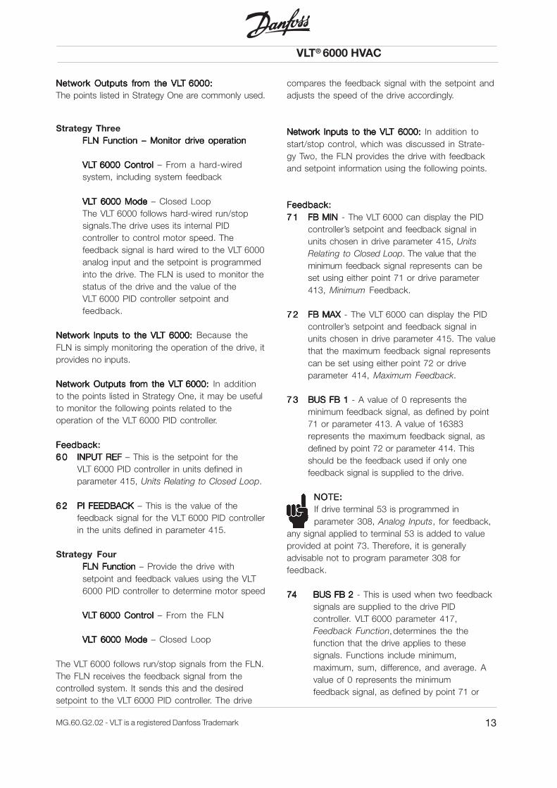
Strategy ThreeFLN FunctionFLN FunctionFLN FunctionFLN FunctionFLN Function – Monitor drive operation– Monitor drive operation– Monitor drive operation– Monitor drive operation– Monitor drive operation
VLVLVLVLVLT 6000 ContrT 6000 ContrT 6000 ContrT 6000 ContrT 6000 Control ol ol ol ol – From a hard-wiredsystem, including system feedback
VLVLVLVLVLT 6000 ModeT 6000 ModeT 6000 ModeT 6000 ModeT 6000 Mode – Closed LoopThe VLT 6000 follows hard-wired run/stopsignals.The drive uses its internal PIDcontroller to control motor speed. Thefeedback signal is hard wired to the VLT 6000analog input and the setpoint is programmedinto the drive. The FLN is used to monitor thestatus of the drive and the value of theVLT 6000 PID controller setpoint andfeedback.
Network Inputs to the VLNetwork Inputs to the VLNetwork Inputs to the VLNetwork Inputs to the VLNetwork Inputs to the VLT 6000:T 6000:T 6000:T 6000:T 6000: Because theFLN is simply monitoring the operation of the drive, itprovides no inputs.
Network Outputs frNetwork Outputs frNetwork Outputs frNetwork Outputs frNetwork Outputs from the VLom the VLom the VLom the VLom the VLT 6000: T 6000: T 6000: T 6000: T 6000: In additionto the points listed in Strategy One, it may be usefulto monitor the following points related to theoperation of the VLT 6000 PID controller.
Feedback:Feedback:Feedback:Feedback:Feedback:6 06 06 06 06 0 INPUT REFINPUT REFINPUT REFINPUT REFINPUT REF – This is the setpoint for the
VLT 6000 PID controller in units defined inparameter 415, Units Relating to Closed Loop.
6 26 26 26 26 2 PI FEEDBACKPI FEEDBACKPI FEEDBACKPI FEEDBACKPI FEEDBACK – This is the value of thefeedback signal for the VLT 6000 PID controllerin the units defined in parameter 415.
Strategy FourFLN FunctionFLN FunctionFLN FunctionFLN FunctionFLN Function – Provide the drive withsetpoint and feedback values using the VLT6000 PID controller to determine motor speed
VLVLVLVLVLT 6000 ContrT 6000 ContrT 6000 ContrT 6000 ContrT 6000 Control ol ol ol ol – From the FLN
VLVLVLVLVLT 6000 ModeT 6000 ModeT 6000 ModeT 6000 ModeT 6000 Mode – Closed Loop
The VLT 6000 follows run/stop signals from the FLN.The FLN receives the feedback signal from thecontrolled system. It sends this and the desiredsetpoint to the VLT 6000 PID controller. The drive
compares the feedback signal with the setpoint andadjusts the speed of the drive accordingly.
Network Inputs to the VLNetwork Inputs to the VLNetwork Inputs to the VLNetwork Inputs to the VLNetwork Inputs to the VLT 6000:T 6000:T 6000:T 6000:T 6000: In addition tostart/stop control, which was discussed in Strate-gy Two, the FLN provides the drive with feedbackand setpoint information using the following points.
Feedback:Feedback:Feedback:Feedback:Feedback:7 17 17 17 17 1 FB MINFB MINFB MINFB MINFB MIN - The VLT 6000 can display the PID
controller’s setpoint and feedback signal inunits chosen in drive parameter 415, UnitsRelating to Closed Loop. The value that theminimum feedback signal represents can beset using either point 71 or drive parameter413, Minimum Feedback.
7 27 27 27 27 2 FB MAX FB MAX FB MAX FB MAX FB MAX - The VLT 6000 can display the PIDcontroller’s setpoint and feedback signal inunits chosen in drive parameter 415. The valuethat the maximum feedback signal representscan be set using either point 72 or driveparameter 414, Maximum Feedback.
7 37 37 37 37 3 BUS FB 1BUS FB 1BUS FB 1BUS FB 1BUS FB 1 - A value of 0 represents theminimum feedback signal, as defined by point71 or parameter 413. A value of 16383represents the maximum feedback signal, asdefined by point 72 or parameter 414. Thisshould be the feedback used if only onefeedback signal is supplied to the drive.
NOTE:NOTE:NOTE:NOTE:NOTE:If drive terminal 53 is programmed inparameter 308, Analog Inputs, for feedback,
any signal applied to terminal 53 is added to valueprovided at point 73. Therefore, it is generallyadvisable not to program parameter 308 forfeedback.
74 BUS FB 274 BUS FB 274 BUS FB 274 BUS FB 274 BUS FB 2 - This is used when two feedbacksignals are supplied to the drive PIDcontroller. VLT 6000 parameter 417,Feedback Function,determines the thefunction that the drive applies to thesesignals. Functions include minimum,maximum, sum, difference, and average. Avalue of 0 represents the minimumfeedback signal, as defined by point 71 or
Network Outputs frNetwork Outputs frNetwork Outputs frNetwork Outputs frNetwork Outputs from the VLom the VLom the VLom the VLom the VLT 6000:T 6000:T 6000:T 6000:T 6000:The points listed in Strategy One are commonly used.

VLT® 6000 HVAC
14 MG.60.G2.02 - VLT is a registered Danfoss Trademark
parameter 413. A value of 16383 representsthe maximum feedback signal, as defined bypoint 72 or parameter 414. See the VLT 6000Operating In Istructions for details.
NOTE:NOTE:NOTE:NOTE:NOTE:If drive terminal 54 is programmed in para-meter 311, Analog Inputs, for feedback,
any signal applied to terminal 54 is added to valueprovided at point 73. Therefore, it is generallyadvisable not to program parameter 311 forfeedback.
Example: Example: Example: Example: Example: In a cooling tower application, the feed-back signal comes from a temperature sensor witha range of 40oF to 140oF. To unbundle bus feedback2 (point 74) for the temperature sensor:
1. Set minimum feedback(point 71 or parameter 413) to 40.
2. Set maximum feedback(point 72 or parameter 414) 140.
3. Intercept = 40 (since the minimum feedbackvalue is 40)
4. Slope can be calculated as follows:
Setpoint:5 05 05 05 05 0 REF MINREF MINREF MINREF MINREF MIN - The VLT 6000 can display the PID
controller’s setpoint and feedback signal inunits. The units displayed are chosen in driveparameter 415. The value that the minimumreference signal represents can be set usingeither point 50 or drive parameter 204.
5 15 15 15 15 1 REF MINREF MINREF MINREF MINREF MIN - The VLT 6000 can display the PIDcontroller’s setpoint and feedback signal inunits. The units displayed are chosen in driveparameter 415. The value that the maximumreference signal represents can be set usingeither point 51 or drive parameter 205.
6 96 96 96 96 9 SETPOINT 1SETPOINT 1SETPOINT 1SETPOINT 1SETPOINT 1 - This is the PID controller’ssetpoint, expressed in the units that werechosen in parameter 415. It can be set toany value between REF MIN (point 50 orparameter 204) and REF MAX (point 51 orparameter 205). If an attempt is made to setpoint 69 to a value outside of this range, thesetpoint will not be changed. SETPOINT 1can also be programmed using parameter418, Setpoint 1.
7 07 07 07 07 0 SETPOINT 2SETPOINT 2SETPOINT 2SETPOINT 2SETPOINT 2 - This PID controller setpoint isused for applications where two feedbacksignals will be compared to independentsetpoints. Refer to the VLT 6000 OperatingInstructions for more details.SETPOINT 2 is expressed in the unitsselected in parameter 415. It can be set toany value between REF MIN (point 50 orparameter 204) and REF MAX (point 51 orparameter 205). If an attempt is made toassign point 70 to a value outside of thisrange, the setpoint will not change.SETPOINT 2 can also be programmedusing parameter 419, Setpoint 2.
PID Controller Adjustments:PID Controller Adjustments:PID Controller Adjustments:PID Controller Adjustments:PID Controller Adjustments:The following points adjust the operation ofthe VLT 6000 PID control loop. They aregenerally set during start-up and onlyadjusted if changes in the system require it.these values can also be set usingparameters.See the VLT 6000 Operating Instructions formore details.
6 16 16 16 16 1 PI STPI STPI STPI STPI STARARARARART FREQ T FREQ T FREQ T FREQ T FREQ (parameter 422) - Thissets the frequency to which the drivewillaccelerate after a start command. After itreaches this frequency, the drive willactivate its PID controller. Point 61 can havea value between the drive’s minimumfrequency (as set in parameter 201) and itsmaximum frequency (as set in parameter202). If an attempt is made to set point 61 toa value outside of this range, thedrive value will not change.
6 36 36 36 36 3 PI GAINPI GAINPI GAINPI GAINPI GAIN (parameter 423) - This sets thevalue of proportional gain for the VLT 6000PID controller. It can have a value between 0and 10.
0.00061
163830.140)(140
PointExistingofRangePoint) Existing of (Slope Range) (Desired
slope
=
×−=
×=

VLT® 6000 HVAC
15MG.60.G2.02 - VLT is a registered Danfoss Trademark
6 46 46 46 46 4 PI I TIMEPI I TIMEPI I TIMEPI I TIMEPI I TIME (parameter 424) - This sets theintegral time for the VLT 6000 PID controller.It can have a value between 0.01 secondsand 9999 (OFF). In order for the controller tofunction properly, this should not be rned off.
6 56 56 56 56 5 PI GAIN LIMITPI GAIN LIMITPI GAIN LIMITPI GAIN LIMITPI GAIN LIMIT (parameter 426) - This setsthe maximum derivative gain for theVLT 6000 PID controller. It can have a valuebetween 5 and 50.
6 66 66 66 66 6 LOWPLOWPLOWPLOWPLOWPASS FLASS FLASS FLASS FLASS FLTRTRTRTRTR (parameter 427) - This setsthe time constant for the noise filter in theVLT 6000 PID controller feedback loop. Itcan have values between 0.01 and 10seconds.
6 86 86 86 86 8 FB FUNCTIONFB FUNCTIONFB FUNCTIONFB FUNCTIONFB FUNCTION (parameter 417) - This setshow the VLT 6000 PID controller responds tothe drive’s two feedback signals. Its value isan integer between 0 and 6. Refer to theVLT 6000 Operating Instructions for the list ofchoices and an explanation of each.
Network Outputs frNetwork Outputs frNetwork Outputs frNetwork Outputs frNetwork Outputs from the VLom the VLom the VLom the VLom the VLT 6000: T 6000: T 6000: T 6000: T 6000: The pointslisted in Strategy One are commonly used.
■■■■■ Network Connection
Table 3 Tightening Torque and Wire Gage
Analog Input Monitoring:Points 87, 88 and 89 can be used to monitor thevalue of the analog control signals applied toterminals 53, 54 and 60. These points are activeeven when NO FUNCTION is programmed for theanalog input of the drive. As a result, it is possible touse the VLT 6000 analog inputs as analog input forthe FLN.
Drive Relay Control:While relay 1 and 2 in the VLT 6000 usually providedrive status indications, these indications aregenerally not needed when the drive is connected toan FLN. In some applications, it can be useful tohave the FLN control these relays. For example, bycontrolling one of the relays, the FLN could selectthe active pump in a pump sequencing system. Forthe FLN to control a drive relay, the appropriateVLT 6000 parameter (323 or 326) must be set toCONTROL WORD 11/12. Setting point 40 or 41 toON will then activate the corresponding relay.
■ ■ ■ ■ ■ VLT 6000 Special Functions
Safety Interlock:The VLT 6000 can accept a safety interlock stopcommand that is hard-wired to the drive controlterminals and another from the FLN. WhenVLT 6000 parameter 304, Digital Inputs, is set toSAFETY INTERLOCK, an open hard-wired safetyinterlock will cause the drive to display ALARM 60EXTERNAL FAULT. Setting point 28 to COAST willdisplay UN. READY in the lower right corner of thedrive’s display. The individual displays for eachallow the operator to determine which devicecaused the trip. VLT 6000 parameter 503, CoastingStop, determines the interaction of these twosafety interlocks. See the VLT 6000 OperatingInstructions for details.
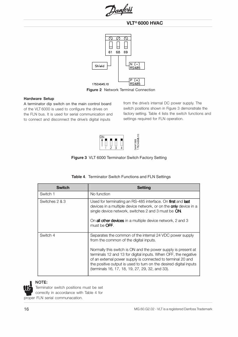
Connect the VLT 6000 to the FLN in accordancewith the following procedure (see Figure 2).
1. Connect signal wires to terminal 68 (P+) andterminal 69 (N-) on main control board of drive.(See tightening torque and wire size in Table 3.)
2. If shielded cabling is used, connect one end ofshield to terminal 61. This terminal is connectedto ground via an internal RC link.
NOTE:NOTE:NOTE:NOTE:NOTE:It is recommended to use shielded, twisted-pair cables to reduce noise betweenconductors.
In addition to the control strategies describedabove, the VLT 6000 provides additional controlflexibility to allow it to integrate into special controlsystemrequirements. The following are just a fewexamples.
Torque Specs
4.5 in Ib/0.5 Nm
Control wire
18 24 AWG, shielded, twisted pair/1.5 mm, shielded twisted pair
VLT® 6000 HVAC
16 MG.60.G2.02 - VLT is a registered Danfoss Trademark
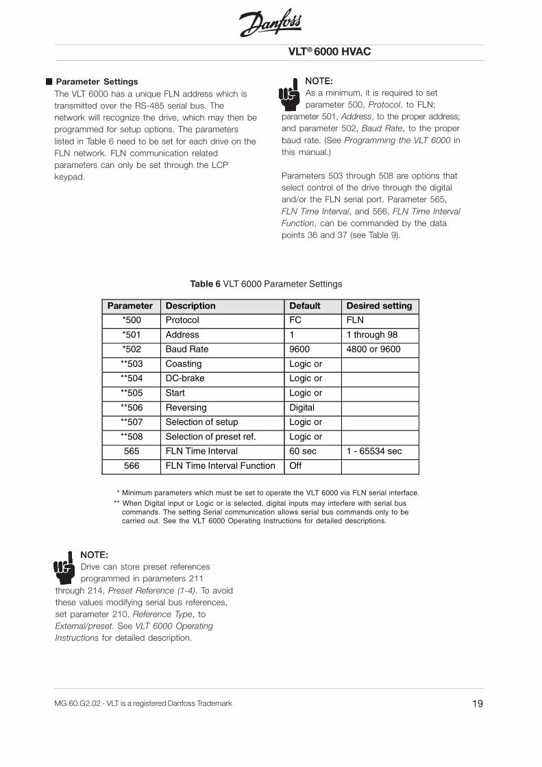
Figure 3 VLT 6000 Terminator Switch Factory Setting
Table 4. Terminator Switch Functions and FLN Settings
Switch Setting
Switch 1 No function
Switches 2 & 3 Used for terminating an RS-485 interface. On ffffiriririrsssstttt and llllaaaasssstttt devices in a multiple device network, or on the oooonnnnllllyyyy device in a single device network, switches 2 and 3 must be OOOONNNN. On aaaalllll l l l ooootttthhhheeeer r r r ddddeeeevvvviiiicccceseseses in a multiple device network, 2 and 3 must be OOOOFFFFFFFF.
Switch 4 Separates the common of the internal 24 VDC power supply from the common of the digital inputs. Normally this switch is ON and the power supply is present at terminals 12 and 13 for digital inputs. When OFF, the negative of an external power supply is connected to terminal 20 and the positive output is used to turn on the desired digital inputs (terminals 16, 17, 18, 19, 27, 29, 32, and 33).
NOTE:NOTE:NOTE:NOTE:NOTE:Terminator switch positions must be setcorrectly in accordance with Table 4 for
proper FLN serial communacation.
Hardware SetupA terminator dip switch on the main control boardof the VLT 6000 is used to configure the drives onthe FLN bus. It is used for serial communication andto connect and disconnect the drive’s digital inputs
from the drive’s internal DC power supply. Theswitch positions shown in Figure 3 demonstrate thefactory setting. Table 4 lists the switch functions andsettings required for FLN operation.
Figure 2 Network Terminal Connection

VLT® 6000 HVAC
17MG.60.G2.02 - VLT is a registered Danfoss Trademark
Electrical Control TerminalsIn most cases, the VLT 6000 will have electricalcontrol connections (see Figure 4) alreadyconnected at equipment installation. The functionaldescription of the drive’s electrical control terminalsin Table 5 are provided primarily for systemmodification and expansion. Two examples of typical
serial interface control connections aredemonstrated in Figures 5 and 6. Many of theseterminals have multiple functions that aredetermined by drive parameter settings. See theVLT 6000 Operating Instructions for detailedinformation.
Table 5 Electrical Control Terminals Functional Description
Number Function
01, 02, 03 Form C relay output. Maximum 240 VAC, 2 A. Minimum 24 VDC, 10 mA or 24 VAC, 100 mA. (Terminal group 01, 02, and 03 is placed in various locations on the power side of the drive, depending upon the model type.)
04, 05 30 VAC, 42.5 VDC, 1 Amp relay outputs can be used for indicating status and warnings.
12, 13 Voltage supply to digital inputs and external transducers. For the 24 VDC to be used for digital inputs, switch 4 on the control card must be closed (position on). The maximum output current is 200 mA.
16 - 33 Digital inputs. R = 2 kohm
<5 V = logical 0
>10 V = logical 1
16 - 33 30 VAC, 42.5 VDC, 1 A relay output can be used for indicating status and warnings.
20 Voltage supply to digital inputs and external transducers. For the 24 VDC to be used for digital inputs, switch 4 on the control card must be closed (position on). The maximum output current is 200 mA.
39 Digital inputs. R = 2 kohm. <5 V = logical 0 , >10 V = logical 1
42, 45 Analog and digital outputs for indicating frequency, reference, current and torque. The analog signal is 0 to 20 mA, or 4 to 20 mA at a maximum of 500 ?. The digital signal is 24 VDC at a minimum of 600 ?.
50 10 VDC, 17 mA maximum analog supply voltage to potentiometer and thermistor.
53, 54 0 to 10 VDC voltage input, R = 10 ?.
55 Common for analog inputs. This common is isolated from the common of all other power supplies. If, for example, the drive s 24 VDC power supply is used to power an external transducer which provides an analog input signal, terminal 55 must be wired to terminal 39.
60 0 to 20 mA or 4 to 20 mA, analog current input, R = 188 ? .
61 Shield for serial communication.
68, 69 RS-485 interface and serial communication. When the drive is connected to an R -485 serial communication bus, DIP switches 2 and 3 must be closed on the first and the last device in the serial connection. On the remaining drives, switches 2 and 3 must be open. The factory setting is closed (position on).

VLT® 6000 HVAC
18 MG.60.G2.02 - VLT is a registered Danfoss Trademark
Typical Control Connection Examples TTTTTwo Feedback Signals:wo Feedback Signals:wo Feedback Signals:wo Feedback Signals:wo Feedback Signals:The drive processes two independent feedbacksignals during closed loop operation (see Figure 6). Itcan respond to the sum, difference, average,minimum or maximum of these signals.
Set Parameter 308, Terminal 53, Analog InputVoltage, to FEEDBACK.Set Parameter 311, Terminal 54, Analog InputVoltage, to FEEDBACKSet Parameter 417, Feedback Function, for thedesired operation.
FigurFigurFigurFigurFigure 6e 6e 6e 6e 6 Two Feedback Signals Connection
TTTTTransmitter Connection:ransmitter Connection:ransmitter Connection:ransmitter Connection:ransmitter Connection:The drive’s internal 24 VDC power supply is used topower an external 4 to 20 mA transducer (seeFigure 5).
FigurFigurFigurFigurFigure 5e 5e 5e 5e 5 Transmitter Connection
Set Parameter 314, Terminal 60, Analog InputCurrent, to correspond to the purpose of the 4 to20 mA signal.Set Parameter 315, Terminal 60, Min. Scaling, to 4 mA.Set Parameter 316, Terminal 60, Max. Scaling, to20 mA.Because the commons of the +24 VDC powersupply and the input reference follower haveseparate circuit commons, it is necessary toconnect a jumper between terminals 39 and 55.
Figure 4 Electrical Control Terminals
VLT® 6000 HVAC
19MG.60.G2.02 - VLT is a registered Danfoss Trademark
Parameter Description Default Desired setting
*500 Protocol FC FLN
*501 Address 1 1 through 98
*502 Baud Rate 9600 4800 or 9600
**503 Coasting Logic or
**504 DC-brake Logic or
**505 Start Logic or
**506 Reversing Digital i t
**507 Selection of setup Logic or
**508 Selection of preset ref. Logic or
565 FLN Time Interval 60 sec 1 - 65534 sec
566 FLN Time Interval Function Off
■■■■■ Parameter Settings
Table 6 VLT 6000 Parameter Settings
NOTE:NOTE:NOTE:NOTE:NOTE:As a minimum, it is required to setparameter 500, Protocol, to FLN;
parameter 501, Address, to the proper address;and parameter 502, Baud Rate, to the properbaud rate. (See Programming the VLT 6000 inthis manual.)
Parameters 503 through 508 are options thatselect control of the drive through the digitaland/or the FLN serial port. Parameter 565,FLN Time Interval, and 566, FLN Time IntervalFunction, can be commanded by the datapoints 36 and 37 (see Table 9).
NOTE:NOTE:NOTE:NOTE:NOTE:Drive can store preset referencesprogrammed in parameters 211
through 214, Preset Reference (1-4). To avoidthese values modifying serial bus references,set parameter 210, Reference Type, toExternal/preset. See VLT 6000 OperatingInstructions for detailed description.
* Minimum parameters which must be set to operate the VLT 6000 via FLN serial interface.** When Digital input or Logic or is selected, digital inputs may interfere with serial bus
commands. The setting Serial communication allows serial bus commands only to becarried out. See the VLT 6000 Operating Instructions for detailed descriptions.
The VLT 6000 has a unique FLN address which istransmitted over the RS-485 serial bus. Thenetwork will recognize the drive, which may then beprogrammed for setup options. The parameterslisted in Table 6 need to be set for each drive on theFLN network. FLN communication relatedparameters can only be set through the LCPkeypad.

VLT® 6000 HVAC
20 MG.60.G2.02 - VLT is a registered Danfoss Trademark
Startup of FLN ControlThis procedure assumes that the VLT 6000frequency converter has been installed properly andis operational in Hand control mode. It also assumesthe Siemens FLN data bus is connected to anoperational controller.Start the VLT 6000 in accordance with the followingprocedure.
1. Ensure that the assumptions in this procedureare correct.
2. Check that the network connections aresecurely fastened in accordance with Figure 2.
Verify compliance with all safety require-ments listed in this manual.
3. Apply power to the VLT 6000.
4. Ensure that the minimum settings listed inTable 6 are selected.
5. Ensure that the switch positions in Figure 3are set correctly.
6. Optional settings may be changed to meet orenhance the drive’s operation, depending onthe application requirements.
7. For FLN control of the drive, press the AUTOSTART key on the VLT 6000 LCP keypad.Drive operation can then be controlled throughthe host network device in accordance withits operation instructions.
NOTE:NOTE:NOTE:NOTE:NOTE:Default setting for point number 35, RunEnable, is OFF. Drive will not operate until
Run Enable ON signal is given through serialcommunication network.
Faults, Warnings and Alarms
DANGER:A stopped motor may start unexpectedlyif faults occur in electronics of drive, or if
an active fault clears, such as a fault in supply ACline, or fault in motor connection, or overload.
The VLT 6000 frequency converter outputs faults,warnings and alarms on the FLN serial bus in anumerical code. The code numbers are described inTable 7. The Reset key is used for manuallyresetting the drive after an alarm (fault trip). In thiscase, the top line of the display will show TRIP(RESET). If the top line of the display shows TRIP(AUTO START), the drive will automatically restart. Ifthe top line of the display shows TRIPLOCK (DISC.MAINS), input power to the drive must be cycled offand on again before the trip can be reset.
Refer to the VLT 6000 Operating Instructions fordetailed descriptions.

VLT® 6000 HVAC
21MG.60.G2.02 - VLT is a registered Danfoss Trademark
TTTTTable 7 able 7 able 7 able 7 able 7 Faults, Warnings and Alarms Description
1) Trip: Requires a reset, either manual or automatic, depending on the the setting of parameter 400, Reset Function.2) Trip lock: Requires AC power cycled on and off and a reset.
Alarms that also have a corresponding warning cannot be reset until warning has been removed, i.e., fault situation is gone.
Points 90-91 refer to warnings. Points 92-94 refer to alarms.
Fault Description Warning Alarm
number Trip1) Trip Lock 2) 1 10 volts low X 2 Live zero X X 4 AC power failure X X X 5 DC link voltage hig X 6 DC link voltage low X 7 Over voltage X X 8 Under voltage X X 9 Inverter time X X 10 Motor time X X 11 Motor thermistor X X 12 Current limit X X 13 Over current X X 14 Ground fault X X 15 Switch mode fault X X 16 Current short circuit X X 17 Serial comm. timeout X X 18 HPFB timeout X X 19 EEPROM on power card X 20 EEPROM o control card X 22 AMA fault X 29 Heat sink temperature too high X X 30 Motor phase U missing X 31 Motor phase V missing X 32 Motor phase W missing X 34 HPFB comm. fault X X 37 Inverter fault X X 39 AMA check par. 104, 106 X 40 AMA check par. 103, 105 X 41 AMA motor too big X 42 AMA motor too small X 60 External fault X 61 Output frequency low X 62 Output frequency high X 63 Output current lo X X 64 Output current high X 65 Feedback low X 66 Feedback hig X 67 Reference low X 68 Reference high X 69 Thermal Auto derating X 99 Unknown alarm X X

VLT® 6000 HVAC
22 MG.60.G2.02 - VLT is a registered Danfoss Trademark
Point Mapping TableThe VLT 6000 parameters, along with the internalvariables and readouts for controlling the drive viathe FLN serial bus, are organized as a Point Map.Not all parameters and readouts are supported bythe FLN protocol. FLN points 01, 02, 20, 29 and 99
are predefined. Available points and a description oftheir characteristics are listed in Table 8. Parameterswhich can be written to (“W” in the Read/Writecolumn) are programmable through the FLN device,others (“R”) are read-only, or read and write (“R/W”).
TTTTTable 8able 8able 8able 8able 8 Point Mapping
Point Number Descriptor
Factory Default
(SI Units)
SI Units Slope (SI Units)
Intercept (SI Units) Range On Text
Off Text
Read/ Write
Param. number
Network Port Type
Note 1
01 CTLR ADDRESS 1 -- 1 0 255 -- -- R 501 Pre-defined
02 APPLICATION 2709 -- 1 0 255 -- -- R -- Pre-defined
Readout Points
{03} FREQ OUTPUT 0 HZ 0.1 0 16383 -- -- R 512 LAI
{06} CURRENT 0 A 0.1 0 16383 -- -- R 514 LAI
{08} POWER 0 KW 1 0 511 -- -- R 515 LAI
{10} KWH 0 KWH 3.1 0 32767 -- -- R 602 LAI
{12} RUN TIME 0 HRS 4.0 0 32767 -- -- R 601 LAI
{13} DC BUS VOLT 0 VOLTS 1 0 1023 -- -- R 518 LAI
{14} OUTPUT VOLT 0 VOLTS 1 0 1023 -- -- R 517 LAI
{15} MOTOR THERM 0 PCT 1 0 255 -- -- R 519 LAI
{16} DRIVE THERM 0 PCT 1 0 255 -- -- R 520 LAI
{17} CURR. SETU 0 -- 1 0 255 -- -- R -- LAI
{18} TIMERS STAT 0 -- -- -- -- LIMIT OK R 527-15 LDI
{19} CURRENT STAT 0 -- -- -- -- LIMIT OK R 527-14 LDI
20 OVRD TIME 1 HRS 1 0 255 -- -- W -- Pre-defined
Status and Command Points
{21} FWD.REV FWD -- -- -- -- REV FWD R 532-8 LDI
{22} CMD FWD.REV FWD -- -- -- -- REV FWD W Cmd-15 LDO
{23} STOP.RUN STOP -- -- -- -- RUN STOP R 527-11 LDI
{24} CMD STP.STRT STOP -- -- -- -- START STOP W Cmd-4 LDO
{25} FREEZE OUT NO -- -- -- -- FREEZE NO R 532-16 LDI
{26} CMD FREEZE FREEZE -- -- -- -- NO FREEZE W Cmd-5 LDO
{27} COAST COAST -- -- -- -- NO COAST R 530-3 LDI
{28} CMD COAST COAST -- -- -- -- NO COAST W Cmd-3 LDO
Common Configuration Points
29 DAY.NIGHT Note 2
DAY -- -- -- 255 NIGHT DAY W -- Pre-defined
{30} CURRENT LIM Note 3
Note 4 A 0.1 0.1 16383 -- -- W 215 LAO
{31} ACCEL TIME 1 Note 4 SEC 1 1 4095 -- -- R/W 206 LAO
{32} DECEL TIME 1 Note 4 SEC 1 1 4095 -- -- R/W 207 LAO

VLT® 6000 HVAC
23MG.60.G2.02 - VLT is a registered Danfoss Trademark
{33} LOCK PANEL Note 5
OPEN -- -- -- -- LOCK OPEN R/W 12-15 LDO
{34} SEL HND.AUTO HAND -- -- -- -- AUTO HAND R 532-13 LDI
{35} RUN ENABLE OFF -- -- -- -- ON OFF W Cmd-6 LDO
{36} BUS TIME 60 SEC 2 2 32767 -- -- R/W 565 LAO
{37} BUSTIME FUNC 0
Note 6
-- 1 0 255 -- -- R/W 566 LAO
{38} F OUT LOW
Note 3
0 HZ 0.1 0 16383 -- -- W 201 LAO
{39} F OUT HIGH Note 3
Note 4 HZ 0.1 0 16383 -- -- W 202 LAO
Physical Output Points
{40} RELAY OUT 1 OFF -- -- -- -- ON OFF W Cmd-11 LDO
{41} RELAY OUT 2 OFF -- -- -- -- ON OFF W Cmd-12 LDO
{42} PI STRT FR. 0 HZ 0.1 0 16383 -- -- R 422 LAI
{43} RELAY 1 STA OFF -- -- -- -- ON OFF R 530-11 LDI
{44} RELAY 1 STA OFF -- -- -- -- ON OFF R 530-12 LDI
{45} CURR. LIM.S Note 4 A 0.1 0.1 16383 -- -- R 215 LAI
{46} F OUT LOW.S 0 HZ 0.1 0 16383 -- -- R 201 LAI
{47} F OUT HIGH.S Note 4 HZ 0.1 0 16383 -- -- R 202 LAI
{48} REF MIN.S 0 UNIT 0.1 -1638.3 32767 -- -- R 204 LAI
{49} REF MAX.S Note 4 UNIT 0.1 -1638.3 32767 -- -- R 205 LAI
Setpoint Related Points
{50} REF MIN Note 3
0 UNIT 0.1 -1638.3 32767 -- -- W 204 LAO
{51} REF MAX Note 3
Note 4 UNIT 0.1 -1638.3 32767 -- -- W 205 LAO
{52} REF STAT OFFREF -- -- -- -- ON.REF OFFREF R 527-8 LDI
{53} BUS REF 0 -- 1 0 32767
Note 7
-- -- R/W -- LAO
{54} SLEEP FREQ.S 0 HZ 0.1 0 16383 -- -- R 404 LAI
{55} WAKEUP FRQ.S Note 4 HZ 0.1 0 16383 -- -- R 405 LAI
{56} SLEEP TIME 301 SEC 1 0 511 -- -- R 403 LAI
{57} SLEEP FREQ Note 3
0 HZ 0.1 0 16383 -- -- W 404 LAO
{58} WAKEUP FREQ Note 3
Note 4 HZ 0.1 0 16383 -- -- W 405 LAO
{59} SLEEP MODE OFF -- -- -- -- SLEEP OFF R 532-3 LDI
PI Loop Related Points
{60} INPUT REF 0 UNIT 0.1 -1638.3 32767 -- -- R 510 LAI
{61} PI STRT FREQ Note 3
0 HZ 0.1 0 16383 -- -- W 422 LAO
{62} PI FEEDBACK 0 UNIT 0.1 -1638.3 32767 -- -- R 511 LAI
{63} PI GAIN 0.3 -- 0.01 0 1023 -- -- R/W 423 LAO
{64} PI I TIME 9999 SEC 0.3051543 0.01 32767 -- -- R/W 424 LAO
Point Number Descriptor
Factory Default
(SI Units)
SI Units Slope (SI Units)
Intercept (SI Units) Range On Text
Off Text
Read/ Write
Param. number
Network Port Type
Note 1

VLT® 6000 HVAC
24 MG.60.G2.02 - VLT is a registered Danfoss Trademark
{65} PI GAIN LIM 5 -- 0.1 0 511 -- -- R/W 426 LAO
{66} LOWPASS FLTR 0.01 SEC 0.01 0 1023 -- -- R/W 427 LAO
{67} SLEEP BOOST OFF -- -- -- -- BOOST OFF R 532-2 LDI
{68} FB FUNC 1
Note 6
-- 1 0 255 -- -- R/W 417 LAO
{69} SETPOINT 1 Note 3
0 UNIT 0.1 -1638.3 32767 -- -- W 418 LAO
{70} SETPOINT 2 Note 3
0 UNIT 0.1 -1638.3 32767 -- -- W 419 LAO
{71} FB MIN Note 3
0 UNIT 0.1 -1638.3 32767 -- -- W 413 LAO
{72} FB MAX Note 3
100.0 UNIT 0.1 -1638.3 32767 -- -- W 414 LAO
{73} BUS FB 1 0 -- 1 0 16383 -- -- R/W 535 LAO
{74} BUS FB 2 0 -- 1 0 16383 -- -- R/W 536 LAO
Miscellaneous Points
{75} AUTO RAMP OFF -- -- -- -- ACTIVE OFF R 532-0 LDI
{76} VOLT STAT OK -- -- -- -- LIMIT OK R 527-13 LDI
{77} INVERT STA OK -- -- -- -- STALL OK R 527-12 LDI
{78} FREQ STAT OUTRNG -- -- -- -- IN.RNG OUTRNG R 527-10 LDI
{79} CTRL STAT LOCAL -- -- -- -- BUS LOCAL R 527-9 LDI
{80} DRV ENA STAT NOTENA -- -- -- -- ENABLE NOTENA R 527-2 LDI
{81} DRV RDY STAT NOTRDY -- -- -- -- READY NOTRDY R 527-1 LDI
{82} DRVCTRL STAT NOTRDY -- -- -- -- READY NOTRDY R 527-0 LDI
{84} RESET NO -- -- -- -- RESET NO R 530-7 LDI
{85} START OFF -- -- -- -- ON OFF R 530-6 LDI
{86} Q.STOP Q.STOP -- -- -- -- NO Q.STOP R 530-4 LDI
{87} TERM 53 0 VOLTS 0.1 0 255 -- -- R 522 LAI
{88} TERM 54 0 VOLTS 0.1 0 255 -- -- R 523 LAI
{89} TERM 60 0 MILAMP 0.1 0 255 -- -- R 524 LAI
Error Related Points
{90} OK.WARNING OK -- -- -- -- WARN OK R 527-7 LDI
{91} LAST WARNING 0 Note 8
-- 1 0 255 -- -- R -- LAI
{92} OK.FAULT OK -- -- -- -- FAULT OK R 527-3 LDI
{93} LAST FAULT 0 Note 8
-- 1 0 255 -- -- R 615 LAI
{94} RESET FAULT NO -- -- -- -- RESET NO W -- LDO
{95} SETPOINT 1.S 0 UNIT 0.1 -1638.3 32767 -- -- R 418 LAI
{96} SETPOINT 2.S 0 UNIT 0.1 -1638.3 32767 -- -- R 419 LAI
{97} FB MIN.S 0 UNIT 0.1 -1638.3 32767 -- -- R 413 LAI
{98} FB MAX.S 100.0 UNIT 0.1 -1638.3 32767 -- -- R 414 LAI
99 ERROR STATUS Note 2
0 -- 1 0 255 -- -- R -- Pre-defined
Point Number Descriptor
Factory Default
(SI Units)
SI Units Slope (SI Units)
Intercept (SI Units) Range On Text
Off Text
Read/ Write
Param. number
Network Port Type
Note 1

VLT® 6000 HVAC
25MG.60.G2.02 - VLT is a registered Danfoss Trademark
Point Mapping Table Notes:
Point numbers that appear in brackets { } may be unbundled at the field panel.
Note 1:Note 1:Note 1:Note 1:Note 1: LAI stands for “Logical Analog Input.” This is an analog value that the VLT 6000 provides to theFLN network. Itsvalue is a feedback indicating the status of a physical input to the drive.LAO stands for “Logical Analog Output.” This is an analog output from the FLN network to theVLT 6000. It is used to control the operation of the drive.LDI stands for “Logical Digital Input.” This is a digital (ON/OFF) signal from the VLT 6000 to theFLN network. It indicates the operation of the drive.LDO stands for “Logical Digital Output.” This is a digital (ON/OFF) signal from the FLN network tothe VLT 6000. It is used to control or indicate the operation of the drive.
Note 2:Note 2:Note 2:Note 2:Note 2: Points 29 and 99 are present but not used in this application.
Note 3:Note 3:Note 3:Note 3:Note 3: These points will accept any value within the range of the point even though the drive hasdifferent upper and/or lower limits for these points. This is because the upper and lower limits forthese points can vary depending on settings of other points or the drive size. Consult the VLT6000 Operating Instructions for values.
Twelve special read-only points can be used for checking if the value actually changed or thechange was rejected. These 12 read-only points should also be used for monitoring databaseCOVs which the others cannot.The read-only points are designated by a descriptor similar tothe original point with a suffix “.S” added.
Below is a list of pairing where the points in parenthesis are the read-only points:30 (45), 38 (46), 39 (47), 50 (48), 51 (49), 57 (54), 58 (55), 61 (42), 69 (95), 70 (96), 71 (97), 72(98).
Note 4:Note 4:Note 4:Note 4:Note 4: The default value depends on the drive. Consult the VLT 6000 Operating Instructions for values.
Note 5:Note 5:Note 5:Note 5:Note 5: When LOCK PANEL is set to LOCK, the “Hand Start”, “Off Stop”, “Auto Start” and “Reset”keys on the VLT 6000 keypad will be disabled. Four parameters in the drive will changesimultaneously. Local programming of the drive will also be locked except for parameter 016,Lock for Data Change, which can disable the programming lock.
Note 6:Note 6:Note 6:Note 6:Note 6: Consult the VLT 6000 Operating Instructions for choice options.
Note 7:Note 7:Note 7:Note 7:Note 7: The number 32767 equals 200% of Bus Ref range value.
Note 8:Note 8:Note 8:Note 8:Note 8: Use Table 7, Faults, Warnings and Alarms, to determine the FAULT or WARNING correspondingto a number.

VLT® 6000 HVAC
26 MG.60.G2.02 - VLT is a registered Danfoss Trademark
Point Database Definitions TTTTTable 9able 9able 9able 9able 9 Point Database Definitions
01 CTLR ADDRESS Predefined device address.02 APPLICATION Predefined FLN application for use with VLT 6000 drive.03 FREQ OUTPUT Displays drive speed in hertz.06 CURRENT Displays drive output current in amps.08 POWER Displays drive power output in kilowatts.10 KWH Displays drive cumulative energy output in kilowatt-hours.12 RUN TIME Displays number of hours drive has supplied power to motor.13 DC BUS VOLT Displays drive voltage at DC bus in DC volts.14 OUTPUT VOLT Displays output voltage to motor in AC volts.15 MOTOR THERM Displays motor thermal load in percentage.16 DRIVE THERM Displays drive thermal load in percentage.17 CURR. SETUP Displays parameter setup number currently controlling drive.18 TIMERS STAT Displays if temperature limit of motor, drive or motor thermistor has been exceeded.19 CURRENT STAT Displays if drive is operating in current limit.20 OVRD TIME Not used.21 FWD.REV Displays direction of motor rotation, forward or reverse.22 CMD FWD.REV Commands direction of motor rotation.23 STOP.RUN Displays drive RUN/STOP status.24 CMD STP.STRT Commands drive to start or stop.25 FREEZE OUT Displays if output frequency is in freeze mode at present value.26 CMD FREEZE Commands drive to freeze present output frequency.27 COAST Displays if drive has been given a coast to stop command.28 CMD COAST Commands drive to make motor coast to a stop.29 DAY.NIGHT Selects day or night mode. (Has no effect on drive operation.)30 CURRENT LIM Sets maximum drive output current to motor in amps.31 ACCEL TIME 1 Sets motor ramp up time in seconds.32 DECEL TIME 1 Sets motor ramp down time in seconds.33 LOCK PANEL Used to lock out Hand Start, Off/Start, Auto Start and Reset keys on LCP.34 SEL HAND.AUTO Displays operation in Hand or Auto control mode function.35 RUN ENABLE Used to enable or disable drive operation in auto mode.36 BUS TIME Sets time limit to determine loss of serial communication in seconds.37 BUSTIME FUNC Selects drive response to loss of serial communication.38 F OUT LOW Sets minimum drive output frequency.39 F OUT HIGH Sets maximum drive output frequency.40 RELAY OUT 1 Controls drive relay output 1. Note: Set relay output to corresponding function.41 RELAY OUT 2 Controls drive relay output 2. Note: Set relay output to corresponding function.42 PI STRT FR.S Displays status of point 61.43 RELAY 1 STAT Displays status of FLN command to drive relay output 1.44 RELAY 2 STAT Displays status of FLN command to drive relay output 2.45 CURR. LIM.S Displays status of point 30.46 F OUT LOW.S Displays status of point 38.47 F OUT HIGH.S Displays status of point 39.48 REF MIN.S Displays status of point 50.49 REF MAX.S Displays status of point 51.50 REF MIN Sets lowest frequency reference value for drive.51 REF MAX Sets highest frequency reference value for drive.52 REF STAT Displays if drive is running at commanded reference.
Point Descriptor Definition Number

VLT® 6000 HVAC
27MG.60.G2.02 - VLT is a registered Danfoss Trademark
53 BUS REF Sends drive an external reference signal in percent.54 SLEEP FREQ.S Displays status of point 57.55 WAKEUP FREQ.S Displays status of point 58.56 SLEEP TIME Displays run time at low speed before sleep mode starts.57 SLEEP FREQ Sets output frequency required to activate sleep mode timer.58 WAKEUP FREQ Sets command frequency required to restart motor after sleep mode.59 SLEEP MODE Displays when drive is stopped in sleep mode.60 INPUT REF Displays drive input reference in Hz or as selected in parameter 415.61 PI STRT FREQ Sets drive frequency after start at which PID control is activated.62 PI FEEDBACK Displays resulting feedback value in units selected in parameter 415.63 PI GAIN Sets proportional gain of PID controller in percentage.64 PI TIME Sets integral time of PID controller in seconds.65 PI GAIN LIM Sets maximum gain for differentiator of PID controller.66 LOWPASS FILTER Sets lowpass filter time constant for feedback circuit.67 SLEEP BOOST Displays sleep boost set point in percentage.68 FB FUNC Selects calculation method when two feedback signals are used.69 SETPOINT 1 Sets setpoint for feedback 1 in units selected in parameter 415.70 SETPOINT 2 Sets setpoint for feedback 2 in units selected in parameter 415.71 FB MIN Sets minimum feedback signal value in units selected in parameter 415.72 FB MAX Sets maximum feedback signal value in units selected in parameter 415.73 BUS FB 1 Supplies feedback value for bus feedback 1 in percent.74 BUS FB 2 Supplies feedback value for bus feedback 2 in percent.75 AUTO RAMP Displays when drive deceleration rate is extended due to auto ramping.76 VOLT STAT Displays if drive DC bus voltage exceeds high/low warning limits.77 INVERT STAT Displays drive inverter status, ok or stall.78 FREQ STAT Displays if drive is running outside of frequency limits of parameters 223 and 224.79 CTRL STAT Displays whether drive is in local control or FLN serial bus.80 DRV ENA STAT Displays if drive is enabled to start when run command given.81 DRV RDY STAT Displays if drive control is ready or if a trip has occurred.82 DRVCTRL STAT Displays drive control status as ready or not ready.84 RESET Displays if a fault reset command has been given via serial bus.85 START Displays if a run command has been given via serial bus.86 Q.STOP Displays if a stop command has been given via serial bus.87 TERM 53 Displays voltage value of signal on terminal 53 in volts.88 TERM 54 Displays voltage value of signal on terminal 54 in volts.89 TERM 60 Displays current value of signal on terminal 60 in mA.90 OK.WARNING Displays if drive is in a warning condition.91 LAST WARNING Displays last drive warning.92 OK.FAULT Displays if drive has been tripped due to a fault.93 LAST FAULT Displays last drive fault trip.94 RESET FAULT Resets drive faults and resumes normal drive operation.95 SETPOINT 1.S Displays status of point 69.96 SETPOINT 2.S Displays status of point 70.97 FB MIN.S Displays status of point 71.98 FB MAX.S Displays status of point 72.99 ERROR STATUS Not used.
Point Descriptor Definition Number

![VLT Contents Introduction to HVAC - DANFOSS VLT … · · 2010-06-30Various literature for VLT 6000 HVAC: Design Guide ... PVLT,N IVLT,N at 240 V SVLT,N VLT type [kW] [HP] [A] [kVA]](https://static.fdocuments.in/doc/165x107/5af991f07f8b9a5f588e4140/vlt-contents-introduction-to-hvac-danfoss-vlt-literature-for-vlt-6000-hvac.jpg)