
VLSI_ImageCompression_EncryptionRead
5
A VLSI Implementation of a New Simultaneous Images Compression and Encryption Method Maher Jridi, Member, IEEE , and Ayman AlFalou, Senior, IEEE D´ epartement d’opto ´ electronique, Laboratoire L@bISEN 20 rue cuirass ´ e Bretagne CS 42807, 29228 Brest Cedex 2, France e-mail: ([email protected] and [email protected]) Abstract —In this manuscri pt, we describe a fully pipeli ned singl e chip arch itec tur e for impl emen ting a new simu ltaneous image compression and encryption method suitable for real-time applications. The proposed method exploits the DCT properties to achieve the compression and the encryption simultaneously. First, to realize the compression, 8-point DCT applied to several images are done. Second, contrary to traditional compression algorithms, only some spec ial points of DCT outputs are multi plex ed. For the enc ryp tion pr oce ss, a random number is gen erated and added to some spe cifi c DCT coeffic ien ts. On the other hand, to enhance the material implementation of the proposed method, a spe cial att ent ion is giv en to the DCT alg ori thm. In fac t, a new way to re ali ze the compress ion based on DCT algori thm and to redu ce, at the same time , the materia l req uir emen ts of the compression process is presented. Simulation results show a compress ion rati o high er than 65 % and a PSNR about 28 dB. The proposed architecture can be implemented in FPGA to yield a throughput of 206 MS/s which allows the processing of more than 30 frames per second for 1024x1024 images. I. I NTRODUCTION Reconfigurable hardware in the form of Field Programmable Gat e Arr ays (FPGAs ) have bee n pro pos ed to obtain hig h performance and economical price to implement image pro- cessing applications like face recognition, detector or airport sec uri ty [1]. For these app lic ati ons , we nee d to use com- muni cati on syste ms with a good security level (encrypt ion) and an acceptable transmission rate (compression rate). In the literature, several encryption and compression techniques can be found. However, for some applications such as detectors, the enc ryp tio n and the compre ssi on tec hni ques can not be dep loy ed ind epe ndentl y and in a cas cad e manner wit hou t con sid eri ng the impac t of one tec hni que ov er ano the r [2] . To sol ve thi s pro ble m, we de vel ope d a ne w techni que to simultaneously compress and encrypt multiple images [3]. The main idea of our approach consists, firstly, in multiplexing the spectra of different transformed images (to be compressed and encrypte d) by a Disc rete Cosine Trans form (DCT) and sec ond ly in imple men tin g the pro pos ed sys tem in FPGA. Conseq uen tl y , spe cia l att ent ion is gi ven to the DCT alg o- rith m impl emen tation in the conte xt of imag e comp ress ion. In fac t, the DCT is the heart of the propo sed compres sio n and enc ryp ti on met hod . It has been wid ely used in spe ech and image comp ress ion due to its good ener gy comp acti on [4]. However its computational requirement is a heavy burden in the rea l time simult ane ous compression and enc ryp tio n application. Different DCT architectures have been proposed to exploit signal proprieties to improve the tradeoff between comp utat ion time and hard ware requ irement. Among these, the DCT alg ori thm propo sed by Loe ffler [5] , has opene d a new area in digital signal processing by reducing the number of req uir ed mul tip lic ati ons to the theoretic al li mit. In thi s paper we use the DCT architecture for image compression and we demonstrate that the number of arithmetic operators can be reduc ed witho ut dramatic ally decre asing the comp ress ed image quality. In fact, by expl oiti ng the spacial corr elat ion of inp ut image s, we can reduc e the number of ari thmeti c operators from 11 multipliers and 29 adders to 4 multipliers and 14 adders. Simultaneously, in order to perform the security le ve l, a second sta ge a usi ng ran dom number gen era tor is applied to some specific DCT outputs. Thi s pap er is or ga niz ed as fol lo ws: the des cri pti on of the proposed simultaneous compression and encryption method is presented in section II. Section III is dedicated to the optimiza- tion of the DCT arch itec ture . Impl emen tati on results using FPGA are illustrated in the last section before conclusion. II. METHOD PRINCIPLE We pr oposed a new techni que, ba sed on our methods pre sen ted in [3] and [6] , whi ch can car ry out compre ssi on and simultaneous encryption using random number generator and Dis cre te Cosine Trans for m (DCT). The mai n idea of our approach consists in multiplexing the spectra of different transformed images separately by a DCT. The choice of the DCT is justi fied by the use of the DCT in many standards such as JPEG [7], MPEG [8] and ITU-T H261 [9]. More ove r, we need fewer DCT coef ficie nts than DFT coe ffi cients to get a goo d app rox ima tion to a typ ica l signal [10]. In fact, by applying the DCT, the most of the signal information tends to be concentrated in a few low-frequency components. Consequently, the higher frequency coefficients are small in magnitude and can be ignored in the compression and encryption process. Fig . 1 pre sen ts the syn opt ic dia gram of the pro pos ed com- pression and encryption system. In the left side, 4 input gray lev el imag es are presente d ( P 1, P 2, P 3, P 4). To apply to each of these images a full parallel DCT algorithm, we need to parallelize each image by blocks of 8 pixels. This operation can be done by a serial to parallel block composed by 8 flip- flops. Th e n, 4 DCT bl oc ks ar e us ed to t ra nsf or m th e 4 in pu t 978-1-4244-6494-4/10/ $26.00 ©2010 IEEE
-
Upload
qsashutosh -
Category
Documents
-
view
216 -
download
0
Transcript of VLSI_ImageCompression_EncryptionRead
8/8/2019 VLSI_ImageCompression_EncryptionRead
http://slidepdf.com/reader/full/vlsiimagecompressionencryptionread 1/5
A VLSI Implementation of a New SimultaneousImages Compression and Encryption Method
Maher Jridi, Member, IEEE , and Ayman AlFalou, Senior, IEEE
Departement d’opto electronique, Laboratoire L@bISEN20 rue cuirass e Bretagne CS 42807, 29228 Brest Cedex 2, Francee-mail: ([email protected] and [email protected])
Abstract —In this manuscript, we describe a fully pipelinedsingle chip architecture for implementing a new simultaneousimage compression and encryption method suitable for real-timeapplications. The proposed method exploits the DCT properties toachieve the compression and the encryption simultaneously. First,to realize the compression, 8-point DCT applied to several imagesare done. Second, contrary to traditional compression algorithms,only some special points of DCT outputs are multiplexed. Forthe encryption process, a random number is generated andadded to some specic DCT coefcients. On the other hand,to enhance the material implementation of the proposed method,a special attention is given to the DCT algorithm. In fact, anew way to realize the compression based on DCT algorithmand to reduce, at the same time, the material requirements of the compression process is presented. Simulation results show acompression ratio higher than 65 % and a PSNR about 28 dB.The proposed architecture can be implemented in FPGA to yielda throughput of 206 MS/s which allows the processing of morethan 30 frames per second for 1024x1024 images.
I. INTRODUCTION
Recongurable hardware in the form of Field ProgrammableGate Arrays (FPGAs) have been proposed to obtain highperformance and economical price to implement image pro-
cessing applications like face recognition, detector or airportsecurity [1]. For these applications, we need to use com-munication systems with a good security level (encryption)and an acceptable transmission rate (compression rate). In theliterature, several encryption and compression techniques canbe found. However, for some applications such as detectors,the encryption and the compression techniques cannot bedeployed independently and in a cascade manner withoutconsidering the impact of one technique over another [2].To solve this problem, we developed a new technique tosimultaneously compress and encrypt multiple images [3].The main idea of our approach consists, rstly, in multiplexingthe spectra of different transformed images (to be compressedand encrypted) by a Discrete Cosine Transform (DCT) andsecondly in implementing the proposed system in FPGA.Consequently, special attention is given to the DCT algo-rithm implementation in the context of image compression.In fact, the DCT is the heart of the proposed compressionand encryption method. It has been widely used in speechand image compression due to its good energy compaction[4]. However its computational requirement is a heavy burdenin the real time simultaneous compression and encryptionapplication. Different DCT architectures have been proposed
to exploit signal proprieties to improve the tradeoff betweencomputation time and hardware requirement. Among these,the DCT algorithm proposed by Loefer [5], has opened anew area in digital signal processing by reducing the numberof required multiplications to the theoretical limit. In thispaper we use the DCT architecture for image compression andwe demonstrate that the number of arithmetic operators canbe reduced without dramatically decreasing the compressed
image quality. In fact, by exploiting the spacial correlationof input images, we can reduce the number of arithmeticoperators from 11 multipliers and 29 adders to 4 multipliersand 14 adders. Simultaneously, in order to perform the securitylevel, a second stage a using random number generator isapplied to some specic DCT outputs.This paper is organized as follows: the description of theproposed simultaneous compression and encryption method ispresented in section II. Section III is dedicated to the optimiza-tion of the DCT architecture. Implementation results usingFPGA are illustrated in the last section before conclusion.
I I . M ETHOD PRINCIPLE
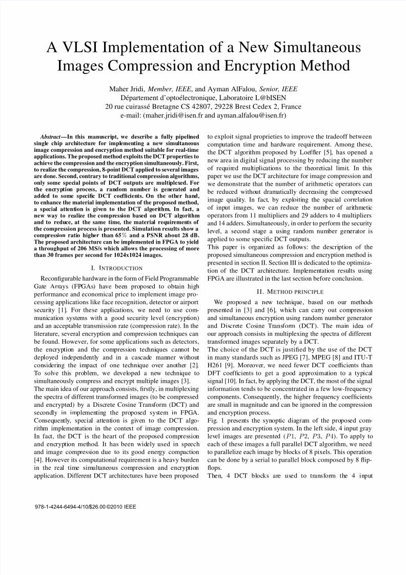
We proposed a new technique, based on our methodspresented in [3] and [6], which can carry out compressionand simultaneous encryption using random number generatorand Discrete Cosine Transform (DCT). The main idea of our approach consists in multiplexing the spectra of differenttransformed images separately by a DCT.The choice of the DCT is justied by the use of the DCTin many standards such as JPEG [7], MPEG [8] and ITU-TH261 [9]. Moreover, we need fewer DCT coefcients thanDFT coefcients to get a good approximation to a typicalsignal [10]. In fact, by applying the DCT, the most of the signalinformation tends to be concentrated in a few low-frequencycomponents. Consequently, the higher frequency coefcientsare small in magnitude and can be ignored in the compressionand encryption process.Fig. 1 presents the synoptic diagram of the proposed com-pression and encryption system. In the left side, 4 input graylevel images are presented ( P 1, P 2, P 3, P 4). To apply toeach of these images a full parallel DCT algorithm, we needto parallelize each image by blocks of 8 pixels. This operationcan be done by a serial to parallel block composed by 8 ip-ops.Then, 4 DCT blocks are used to transform the 4 input
978-1-4244-6494-4/10/$26.00 ©2010 IEEE
8/8/2019 VLSI_ImageCompression_EncryptionRead
http://slidepdf.com/reader/full/vlsiimagecompressionencryptionread 2/5
Fig. 1. Synoptic diagram of the proposed compression and encryption system
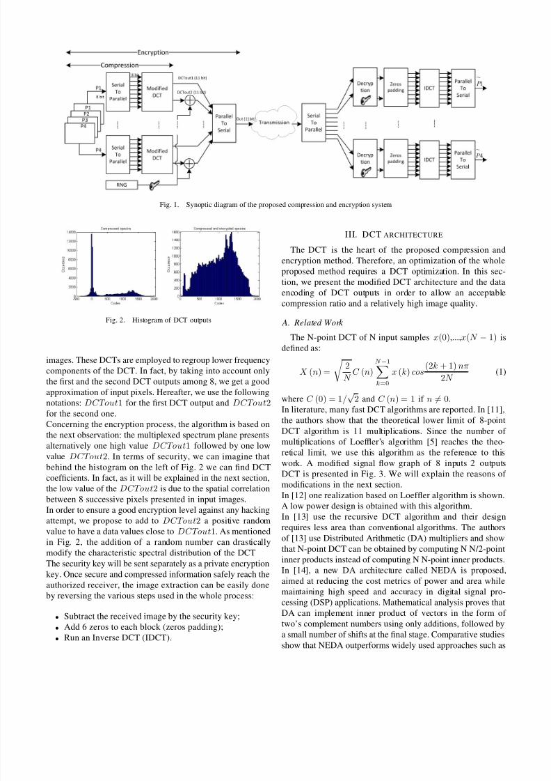
Fig. 2. Histogram of DCT outputs
images. These DCTs are employed to regroup lower frequencycomponents of the DCT. In fact, by taking into account onlythe rst and the second DCT outputs among 8, we get a goodapproximation of input pixels. Hereafter, we use the followingnotations: DCTout 1 for the rst DCT output and DCTout 2for the second one.Concerning the encryption process, the algorithm is based onthe next observation: the multiplexed spectrum plane presentsalternatively one high value DCTout 1 followed by one lowvalue DCTout 2. In terms of security, we can imagine thatbehind the histogram on the left of Fig. 2 we can nd DCTcoefcients. In fact, as it will be explained in the next section,the low value of the DCTout 2 is due to the spatial correlationbetween 8 successive pixels presented in input images.In order to ensure a good encryption level against any hackingattempt, we propose to add to DCTout 2 a positive randomvalue to have a data values close to DCTout 1. As mentionedin Fig. 2, the addition of a random number can drasticallymodify the characteristic spectral distribution of the DCTThe security key will be sent separately as a private encryptionkey. Once secure and compressed information safely reach theauthorized receiver, the image extraction can be easily doneby reversing the various steps used in the whole process:
• Subtract the received image by the security key;• Add 6 zeros to each block (zeros padding);• Run an Inverse DCT (IDCT).
III. DCT ARCHITECTURE
The DCT is the heart of the proposed compression andencryption method. Therefore, an optimization of the whole
proposed method requires a DCT optimization. In this sec-tion, we present the modied DCT architecture and the dataencoding of DCT outputs in order to allow an acceptablecompression ratio and a relatively high image quality.
A. Related Work
The N-point DCT of N input samples x(0) ,...,x(N −1) isdened as:
X (n) = 2N
C (n)N − 1
k =0
x (k) cos(2k + 1) nπ
2N (1)
where C (0) = 1 / √2 and C (n) = 1 if n = 0 .
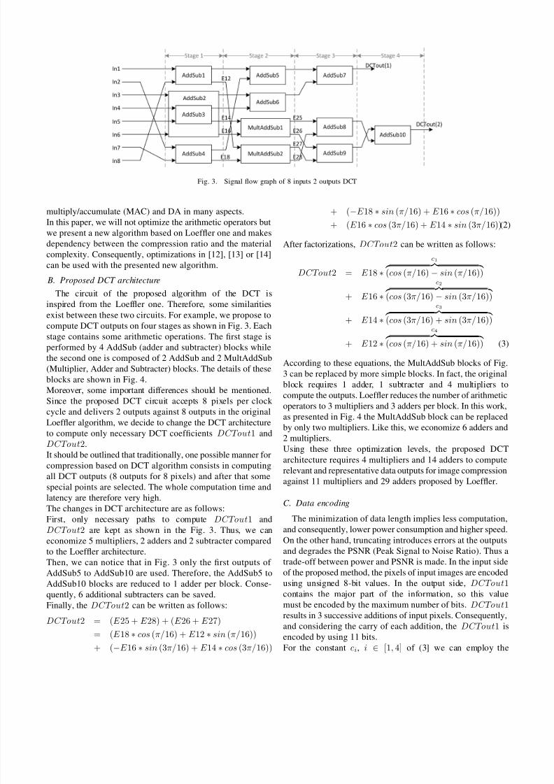
In literature, many fast DCT algorithms are reported. In [11],the authors show that the theoretical lower limit of 8-pointDCT algorithm is 11 multiplications. Since the number of multiplications of Loefer’s algorithm [5] reaches the theo-retical limit, we use this algorithm as the reference to thiswork. A modied signal ow graph of 8 inputs 2 outputsDCT is presented in Fig. 3. We will explain the reasons of modications in the next section.In [12] one realization based on Loefer algorithm is shown.A low power design is obtained with this algorithm.In [13] use the recursive DCT algorithm and their designrequires less area than conventional algorithms. The authorsof [13] use Distributed Arithmetic (DA) multipliers and showthat N-point DCT can be obtained by computing N N/2-pointinner products instead of computing N N-point inner products.In [14], a new DA architecture called NEDA is proposed,aimed at reducing the cost metrics of power and area whilemaintaining high speed and accuracy in digital signal pro-cessing (DSP) applications. Mathematical analysis proves thatDA can implement inner product of vectors in the form of two’s complement numbers using only additions, followed bya small number of shifts at the nal stage. Comparative studiesshow that NEDA outperforms widely used approaches such as
8/8/2019 VLSI_ImageCompression_EncryptionRead
http://slidepdf.com/reader/full/vlsiimagecompressionencryptionread 3/5
Fig. 3. Signal ow graph of 8 inputs 2 outputs DCT
multiply/accumulate (MAC) and DA in many aspects.In this paper, we will not optimize the arithmetic operators butwe present a new algorithm based on Loefer one and makesdependency between the compression ratio and the materialcomplexity. Consequently, optimizations in [12], [13] or [14]can be used with the presented new algorithm.
B. Proposed DCT architecture
The circuit of the proposed algorithm of the DCT isinspired from the Loefer one. Therefore, some similaritiesexist between these two circuits. For example, we propose tocompute DCT outputs on four stages as shown in Fig. 3. Eachstage contains some arithmetic operations. The rst stage isperformed by 4 AddSub (adder and subtracter) blocks whilethe second one is composed of 2 AddSub and 2 MultAddSub(Multiplier, Adder and Subtracter) blocks. The details of theseblocks are shown in Fig. 4.Moreover, some important differences should be mentioned.Since the proposed DCT circuit accepts 8 pixels per clock
cycle and delivers 2 outputs against 8 outputs in the originalLoefer algorithm, we decide to change the DCT architectureto compute only necessary DCT coefcients DCTout 1 andDCTout 2.It should be outlined that traditionally, one possible manner forcompression based on DCT algorithm consists in computingall DCT outputs (8 outputs for 8 pixels) and after that somespecial points are selected. The whole computation time andlatency are therefore very high.The changes in DCT architecture are as follows:First, only necessary paths to compute DCTout 1 andDCTout 2 are kept as shown in the Fig. 3. Thus, we caneconomize 5 multipliers, 2 adders and 2 subtracter comparedto the Loefer architecture.Then, we can notice that in Fig. 3 only the rst outputs of AddSub5 to AddSub10 are used. Therefore, the AddSub5 toAddSub10 blocks are reduced to 1 adder per block. Conse-quently, 6 additional subtracters can be saved.Finally, the DCTout 2 can be written as follows:
DCTout 2 = ( E 25 + E 28) + ( E 26 + E 27)= ( E 18∗cos (π/ 16) + E 12∗sin (π/ 16))+ ( −E 16∗sin (3π/ 16) + E 14∗cos (3π/ 16))
+ ( −E 18∗sin (π/ 16) + E 16∗cos (π/ 16))+ ( E 16∗cos (3π/ 16) + E 14∗sin (3π/ 16))(2)
After factorizations, DCTout 2 can be written as follows:
DCTout 2 = E 18∗
c 1
(cos (π/ 16) −sin (π/ 16))
+ E 16∗
c 2
(cos (3π/ 16) −sin (3π/ 16))
+ E 14∗
c 3
(cos (3π/ 16) + sin (3π/ 16))
+ E 12∗
c 4
(cos (π/ 16) + sin (π/ 16)) (3)
According to these equations, the MultAddSub blocks of Fig.3 can be replaced by more simple blocks. In fact, the originalblock requires 1 adder, 1 subtracter and 4 multipliers tocompute the outputs. Loefer reduces the number of arithmeticoperators to 3 multipliers and 3 adders per block. In this work,as presented in Fig. 4 the MultAddSub block can be replacedby only two multipliers. Like this, we economize 6 adders and2 multipliers.Using these three optimization levels, the proposed DCTarchitecture requires 4 multipliers and 14 adders to computerelevant and representative data outputs for image compressionagainst 11 multipliers and 29 adders proposed by Loefer.
C. Data encoding
The minimization of data length implies less computation,and consequently, lower power consumption and higher speed.On the other hand, truncating introduces errors at the outputsand degrades the PSNR (Peak Signal to Noise Ratio). Thus atrade-off between power and PSNR is made. In the input sideof the proposed method, the pixels of input images are encodedusing unsigned 8-bit values. In the output side, DCTout 1contains the major part of the information, so this valuemust be encoded by the maximum number of bits. DCTout 1results in 3 successive additions of input pixels. Consequently,and considering the carry of each addition, the DCTout 1 isencoded by using 11 bits.For the constant ci , i ∈[1, 4] of (3] we can employ the
8/8/2019 VLSI_ImageCompression_EncryptionRead
http://slidepdf.com/reader/full/vlsiimagecompressionencryptionread 4/5
Fig. 4. Arithmetic operator blocks
coefcients encoding used in [15] and detailed by the nextequation:
ci = round ci∗28 − 1
−1/c i,max (4)
For DCTout 2 encodage, we can take into account the spatialcorrelation of images. In fact, we can suppose that for imagesize of 256*256 pixels or higher, the block of each 8 adjacentpixels of the same line are very correlated and have a veryclose value. Consequently, signals E12, E14, E16 and E18from Fig. 3 which are the subtraction of input image pixelsfrom In 1 to In 8 have a very low value. In the same way, thesignals E25 to E28 also have a lower value compared to inputpixel images. Consequently, we can limit the DCTout 2 by
−F S
≤DCTout 2
≤F S where F S = 2 8 is the full scale of
the input images.On the other hand, for encryption process, the encryptedDCTout 2 have to be close to DCTout 1 which is in0, 23
∗F S . Consequently, the DCTout 2 is added to r , agenerated random number expressed by the next equation:
r = round (F S + 6∗FS ∗r ) (5)
where r is an uniformly distributed pseudorandom number,0 ≤ r ≤1. Finally, DCTout 1, DCTout 2 are encoded using11 bits.The data encoding allows a high compression ratio. In fact,since the 4 spectra will be regrouped in a single plane, the
consequent compression ratio for input image sizes of S is:
R = 1 −S ∗11bits
4∗S ∗8bits ×100% = 65 .62% (6)
Moreover, for higher compression rate, we can use thecorrelation between the neighboring pixels to encode thesecond DCT coefcient using only 7 bits. The obtainedcompression ratio can achieve a value of about 72%
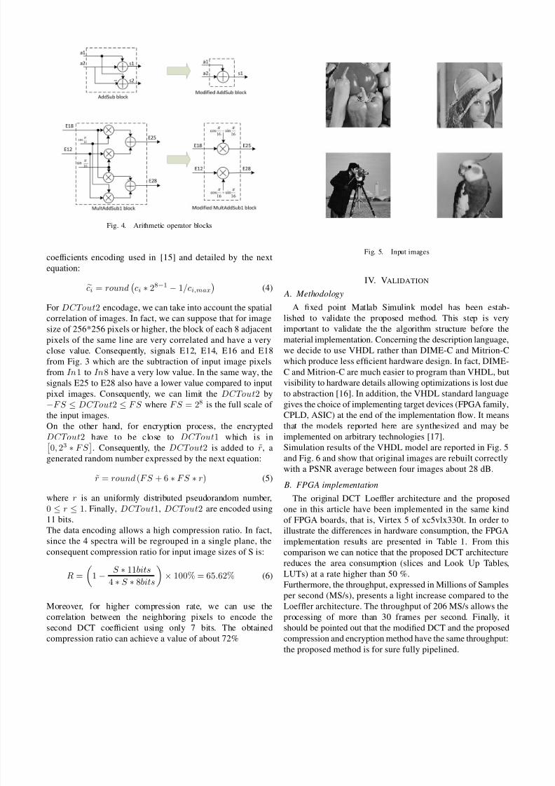
Fig. 5. Input images
IV. VALIDATION
A. Methodology
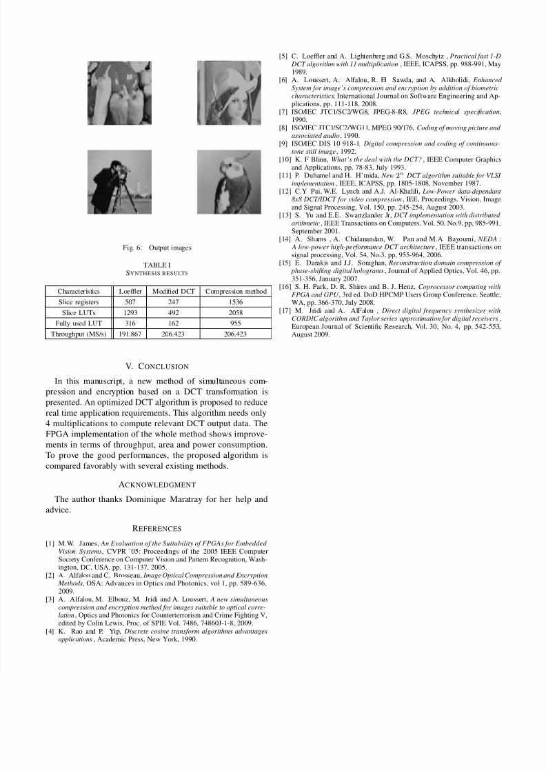
A xed point Matlab Simulink model has been estab-lished to validate the proposed method. This step is veryimportant to validate the the algorithm structure before thematerial implementation. Concerning the description language,we decide to use VHDL rather than DIME-C and Mitrion-Cwhich produce less efcient hardware design. In fact, DIME-C and Mitrion-C are much easier to program than VHDL, butvisibility to hardware details allowing optimizations is lost dueto abstraction [16]. In addition, the VHDL standard languagegives the choice of implementing target devices (FPGA family,CPLD, ASIC) at the end of the implementation ow. It meansthat the models reported here are synthesized and may beimplemented on arbitrary technologies [17].Simulation results of the VHDL model are reported in Fig. 5and Fig. 6 and show that original images are rebuilt correctlywith a PSNR average between four images about 28 dB.
B. FPGA implementation
The original DCT Loefer architecture and the proposedone in this article have been implemented in the same kindof FPGA boards, that is, Virtex 5 of xc5vlx330t. In order toillustrate the differences in hardware consumption, the FPGAimplementation results are presented in Table 1. From thiscomparison we can notice that the proposed DCT architecturereduces the area consumption (slices and Look Up Tables,LUTs) at a rate higher than 50 %.Furthermore, the throughput, expressed in Millions of Samplesper second (MS/s), presents a light increase compared to theLoefer architecture. The throughput of 206 MS/s allows theprocessing of more than 30 frames per second. Finally, itshould be pointed out that the modied DCT and the proposedcompression and encryption method have the same throughput:the proposed method is for sure fully pipelined.
8/8/2019 VLSI_ImageCompression_EncryptionRead
http://slidepdf.com/reader/full/vlsiimagecompressionencryptionread 5/5
Fig. 6. Output images
TABLE ISYNTHESIS RESULTS
Characteristics Loefer Modied DCT Compression method
Slice registers 507 247 1536
Slice LUTs 1293 492 2058
Fully used LUT 316 162 955
Throughput (MS/s) 191.867 206.423 206.423
V. C ONCLUSION
In this manuscript, a new method of simultaneous com-pression and encryption based on a DCT transformation is
presented. An optimized DCT algorithm is proposed to reducereal time application requirements. This algorithm needs only4 multiplications to compute relevant DCT output data. TheFPGA implementation of the whole method shows improve-ments in terms of throughput, area and power consumption.To prove the good performances, the proposed algorithm iscompared favorably with several existing methods.
ACKNOWLEDGMENT
The author thanks Dominique Maratray for her help andadvice.
REFERENCES
[1] M.W. James, An Evaluation of the Suitability of FPGAs for Embedded Vision Systems , CVPR ’05: Proceedings of the 2005 IEEE ComputerSociety Conference on Computer Vision and Pattern Recognition, Wash-ington, DC, USA, pp. 131-137, 2005.
[2] A. Alfalou and C. Brosseau, Image Optical Compression and Encryption Methods , OSA: Advances in Optics and Photonics, vol 1, pp. 589-636,2009.
[3] A. Alfalou, M. Elbouz, M. Jridi and A. Loussert, A new simultaneouscompression and encryption method for images suitable to optical corre-lation , Optics and Photonics for Counterterrorism and Crime Fighting V,edited by Colin Lewis, Proc. of SPIE Vol. 7486, 74860J-1-8, 2009.
[4] K. Rao and P. Yip, Discrete cosine transform algorithms advantagesapplications , Academic Press, New York, 1990.
[5] C. Loefer and A. Lightenberg and G.S. Moschytz , Practical fast 1-D DCT algorithm with 11 multiplication , IEEE, ICAPSS, pp. 988-991, May1989.
[6] A. Loussert, A. Alfalou, R. El Sawda, and A. Alkholidi, Enhanced System for image’s compression and encryption by addition of biometriccharacteristics , International Journal on Software Engineering and Ap-plications, pp. 111-118, 2008.
[7] ISO/IEC JTC1/SC2/WG8, JPEG-8-R8, JPEG technical specication ,1990.
[8] ISO/IEC JTC1/SC2/WG11, MPEG 90/176, Coding of moving picture and
associated audio , 1990.[9] ISO/IEC DIS 10 918-1, Digital compression and coding of continuous-
tone still image , 1992.[10] K. F Blinn, What’s the deal with the DCT? , IEEE Computer Graphics
and Applications, pp. 78-83, July 1993.[11] P. Duhamel and H. H’mida, New 2 n DCT algorithm suitable for VLSI
implementation , IEEE, ICAPSS, pp. 1805-1808, November 1987.[12] C.Y Pai, W.E. Lynch and A.J. Al-Khalili, Low-Power data-dependant
8x8 DCT/IDCT for video compression , IEE, Proceedings. Vision, Imageand Signal Processing, Vol. 150, pp. 245-254, August 2003.
[13] S. Yu and E.E. Swartzlander Jr, DCT implementation with distributed arithmetic , IEEE Transactions on Computers, Vol. 50, No.9, pp, 985-991,September 2001.
[14] A. Shams , A. Chidanandan, W. Pan and M.A Bayoumi, NEDA : A low-power high-performance DCT architecture , IEEE transactions onsignal processing, Vol. 54, No.3, pp, 955-964, 2006.
[15] E. Darakis and J.J. Soraghan, Reconstruction domain compression of
phase-shifting digital holograms , Journal of Applied Optics, Vol. 46, pp.351-356, January 2007.
[16] S. H. Park, D. R. Shires and B. J. Henz, Coprocessor computing withFPGA and GPU , 3rd ed. DoD HPCMP Users Group Conference. Seattle,WA, pp. 366-370, July 2008.
[17] M. Jridi and A. AlFalou , Direct digital frequency synthesizer withCORDIC algorithm and Taylor series approximation for digital receivers ,European Journal of Scientic Research, Vol. 30, No. 4, pp. 542-553,August 2009.


