Vlsi Implementation of Memory Core Using Vhdl.22222
54
CHAPTER: 1 VLSI IMPLEMENTATION OF MEMORY CORE USING VHDL INTRODUCTION: Memory: In its most basic sense, memory refers to any information or data, often in binary format, that a machine or technology can recall and use. There are many different kinds of memory in conventional computers and other devices, and they differ based on the complex design of the hardware in which they're stored. Computer memory is any physical device capable of storing information temporarily or permanently. For example, Random Access Memory (RAM ), is a type of volatile memory and read only memory ( ROM ) is non volatile memory that is stores information on an integrated circuit , and that is used by the operating system , software , hardware , or the user. Below is an example picture of a 512MB DIMM computer memory module . Volatile vs. non-volatile memory: Memory can be either volatile and non-volatile memory. Volatile memory is a temporary memory that loses its contents when the computer or hardware device loses power. Computer RAM is a good example of a volatile memory and is why if your computer freezes or reboots when working on a program you lose anything that hasn't been saved. Non-volatile memory,
-
Upload
sandeep-babu-vannempalli -
Category
Documents
-
view
258 -
download
1
description
VLSI IMPLEMENTATION OF MEMORY CORE USING VHDL.22222
Transcript of Vlsi Implementation of Memory Core Using Vhdl.22222

CHAPTER: 1
VLSI IMPLEMENTATION OF MEMORY CORE USING VHDL
INTRODUCTION:
Memory:
In its most basic sense, memory refers to any information or data, often in binary format, that a machine or technology can recall and use. There are many different kinds of memory in conventional computers and other devices, and they differ based on the complex design of the hardware in which they're stored.
Computer memory is any physical device capable of storing information temporarily or permanently. For example, Random Access Memory (RAM), is a type of volatile memory and read only memory ( ROM ) is non volatile memory that is stores information on an integrated circuit, and that is used by the operating system, software, hardware, or the user. Below is an example picture of a 512MB DIMM computer memory module.
Volatile vs. non-volatile memory:
Memory can be either volatile and non-volatile memory. Volatile memory is a temporary memory that loses its contents when the computer or hardware device loses power. Computer RAM is a good example of a volatile memory and is why if your computer freezes or reboots when working on a program you lose anything that hasn't been saved. Non-volatile memory, sometimes abbreviated as NVRAM, is memory that keeps its contents even if the power is lost. EPROM is a good example of a non-volatile memory.
Memory is not disk storage
It is very common for new computer users to be confused by what parts in the computer are memory. Although both the hard drive and RAM are considered memory, it is more appropriate to refer to RAM as "memory" or "primary memory" and a hard drive as "storage" or "secondary storage" and not memory.
When a program such as your Internet browser is open, it is loaded from your hard drive and placed into RAM, which allows that program to communicate with the processor at higher speeds. Anything you save to your computer such as a picture or video is sent to your hard drive for storage.
When someone asks how much memory is in your computer, it is likely between 1GB and 8GB of Random Access Memory (RAM) and several hundred Gigs of hard disk drive memory (storage). In other words, You will almost always have more hard drive space than RAM.
Comparison chartRAM ROM
Definition:
Random Access Memory or RAM is a form of data storage that can be accessed randomly at any time, in any order and from any physical location., allowing quick access and manipulation.
Read-only memory or ROM is also a form of data storage that can not be easily altered or reprogrammed.Stores instuctions that are not nescesary for re-booting up to make the computer operate when it is switched off.They are hardwired.
Stands for:
Random Access Memory Read-only memory
Use:RAM allows the computer to read data quickly to run applications. It allows reading and writing.
ROM stores the program required to initially boot the computer. It only allows reading.
Volatility:RAM is volatile i.e. its contents are lost when the device is powered off.
It is non-volatile i.e. its contents are retained even when the device is powered off.
Types:The two main types of RAM are static RAM and dynamic RAM.
The types of ROM include PROM, EPROM and EEPROM.
Read Only Memory (ROM):
Read-only memory (ROM) is a type of storage medium that permanently stores data on personal computers (PCs) and other electronic devices. Because ROM is read-only, it cannot be changed; it is permanent and non-volatile, meaning it will also hold its memory even when power is removed. By contrast, random access memory (RAM) is volatile; it is lost when power is removed.
Read-only memory (ROM) is a type of memory storage that is permanently integrated into a personal computer (PC). It contains the programming needed to start a PC which is essential

for boot-up; it performs major input/output tasks and holds programs or software instructions.
There are numerous ROM chips located on the motherboard and a few on expansion boards. The chips are essential for the basic input/output system (BIOS), boot up, reading and writing to peripheral devices, basic data management and the software for basic processes for certain utilities.
Device that allows permanent storage of information:
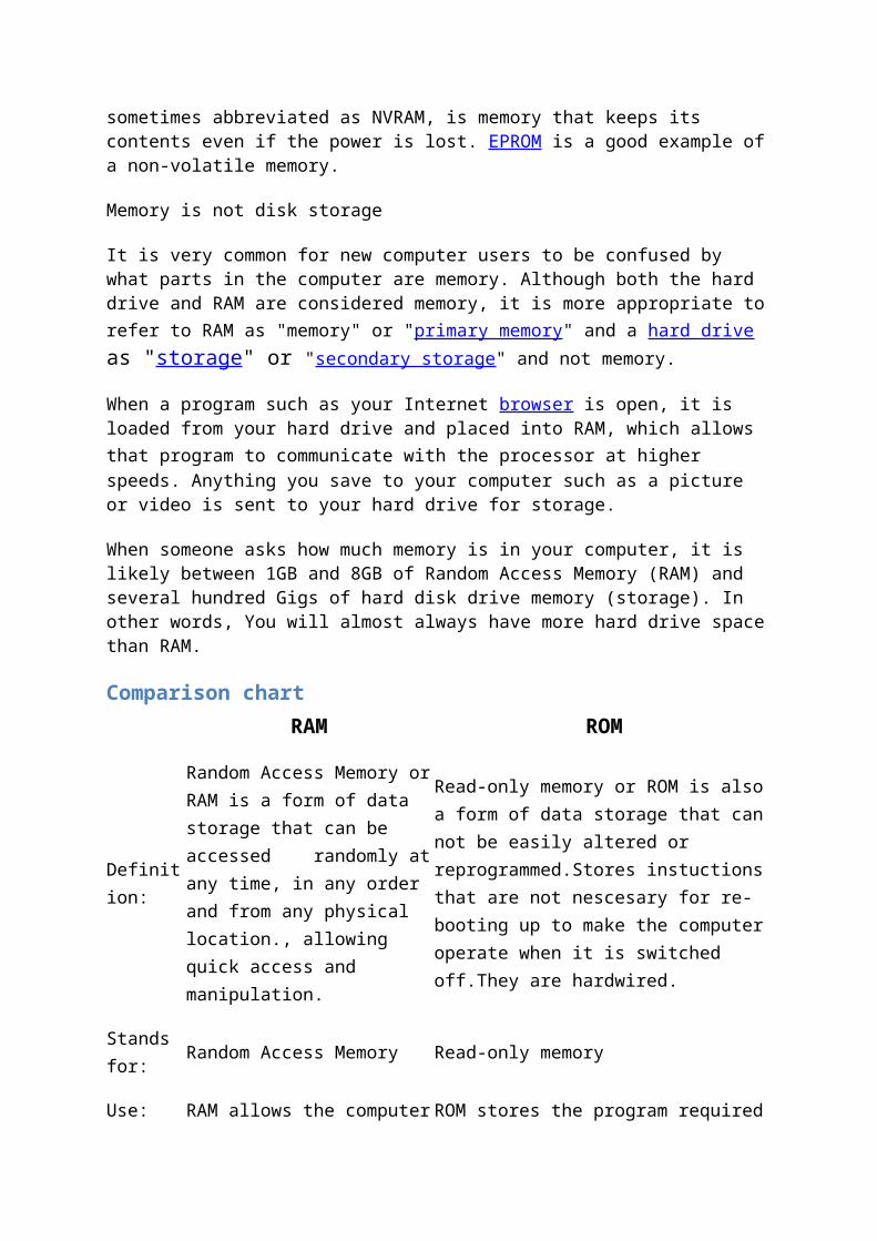
Device has k input (address) lines and n output (data) lines. We can store 2k x n bits of information inside the device. The address lines specify a memory location and the data outputs at any time
represents the value stored at the memory location specified on the address lines.
Block diagram for a ROM:
Types of ROM:
Programmable Read-Only Memory (PROM) Electrically Programmable Read-Only Memory (EPROM) Electrically Erasable Programmable Read-Only Memory (EEPROM; also called Flash
ROM)
Programmable ROM:
Alternatively referred to as a FPROM (field programmable read-only memory) or OTP (one-time programmable) chip, PROM or Programmable ROM is short for Programmable Read Only Memory and is a computer memory chip first developed by Wen Tsing Chow in 1956 that is capable of being programmed once after it has been created. Once the PROM has
been programmed, the information written is permanent and cannot be erased or deleted. A good example of a PROM in a computer is the computer BIOS in early computers.
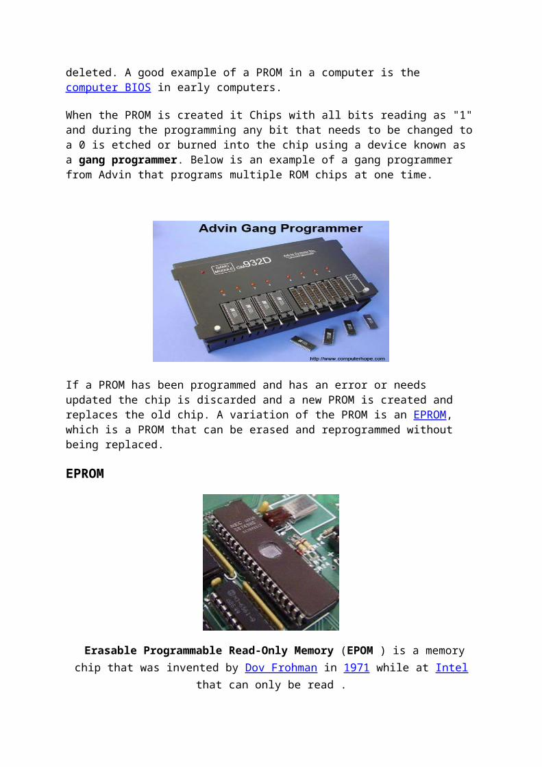
When the PROM is created it Chips with all bits reading as "1" and during the programming any bit that needs to be changed to a 0 is etched or burned into the chip using a device known as a gang programmer. Below is an example of a gang programmer from Advin that programs multiple ROM chips at one time.
If a PROM has been programmed and has an error or needs updated the chip is discarded and a new PROM is created and replaces the old chip. A variation of the PROM is an EPROM, which is a PROM that can be erased and reprogrammed without being replaced.
EPROM
Erasable Programmable Read-Only Memory (EPOM ) is a memory chip that was invented by Dov Frohman in 1971 while at Intel that can only be read .
If exposed to ultra-violet light an EPROM can be reprogrammed if needed, but otherwise does not accept or save any new data. Hardware manufacture use EPROM when it may be needed that the data contained on the EPROM needs to be changed. An EPROM chip is distinguishable by a small quartz crystal (not glass) circle window exposes the chip so that
can be reprogrammed. In the picture shown on this page is an example of an Intel 8048 made by NEC and is an example of an EPROM chip.
Today, EPROM chips are not used in computers and have been replaced by EEPROM chips.
EEPROM
Electrically Erasable Programmable Read-Only Memory, EEPROM is a PROM that can be erased and reprogrammed using an electrical charge that was developed by George Perlegos while at Intel in 1978. Unlike most memory inside a computer, this memory remembers data when the power is turned off.
EEPROM was a replacement for PROM and EPROM chips and is used for later computer's BIOS that were built after 1994. Having a computer with an EEPROM allows a computer user to update the BIOS in their computer without having to open the computer or remove any chips.

CHAPTER: 2
INTRODUCTION OF VLSI
Very-large-scale integration (VLSI) is the process of creating integrated circuits by
combining thousands of transistor-based circuits into a single chip. VLSI began in the 1970s
when complex semiconductor and communication technologies were being developed. The
microprocessor is a VLSI device. The term is no longer as common as it once was, as chips
have increased in complexity into the hundreds of millions of transistors.
Overview
The first semiconductor chips held one transistor each. Subsequent advances added
more and more transistors, and, as a consequence, more individual functions or systems were
integrated over time. The first integrated circuits held only a few devices, perhaps as many as
ten diodes, transistors, resistors and capacitors, making it possible to fabricate one or more
logic gates on a single device. Now known retrospectively as "small-scale integration" (SSI),
improvements in technique led to devices with hundreds of logic gates, known as large-scale
integration (LSI), i.e. systems with at least a thousand logic gates. Current technology has
moved far past this mark and today's microprocessors have many millions of gates and
hundreds of millions of individual transistors.
At one time, there was an effort to name and calibrate various levels of large-
scale integration above VLSI. Terms like Ultra-large-scale Integration (ULSI) were used. But
the huge number of gates and transistors available on common devices has rendered such fine
distinctions moot. Terms suggesting greater than VLSI levels of integration are no longer in
widespread use. Even VLSI is now somewhat quaint, given the common assumption that all
microprocessors are VLSI or better.
As of early 2008, billion-transistor processors are commercially available, an
example of which is Intel's Montecito Itanium chip. This is expected to become more
commonplace as semiconductor fabrication moves from the current generation of 65 nm
processes to the next 45 nm generations (while experiencing new challenges such as

increased variation across process corners). Another notable example is NVIDIA’s 280 series
GPU.
This microprocessor is unique in the fact that its 1.4 Billion transistor count,
capable of a teraflop of performance, is almost entirely dedicated to logic (Itanium's transistor
count is largely due to the 24MB L3 cache). Current designs, as opposed to the earliest
devices, use extensive design automation and automated logic synthesis to lay out the
transistors, enabling higher levels of complexity in the resulting logic functionality. Certain
high-performance logic blocks like the SRAM cell, however, are still designed by hand to
ensure the highest efficiency (sometimes by bending or breaking established design rules to
obtain the last bit of performance by trading stability).
What is VLSI?
VLSI stands for "Very Large Scale Integration". This is the field which
involves packing more and more logic devices into smaller and smaller areas.
VLSI
1. Simply we say Integrated circuit is many transistors on one chip.
2. Design/manufacturing of extremely small, complex circuitry using modified
semiconductor material
3. Integrated circuit (IC) may contain millions of transistors, each a few mm in size
4. Applications wide ranging: most electronic logic devices
History of Scale Integration
late 40s Transistor invented at Bell Labs
late 50s First IC (JK-FF by Jack Kilby at TI)
early 60s Small Scale Integration (SSI)
10s of transistors on a chip
late 60s Medium Scale Integration (MSI)
100s of transistors on a chip
early 70s Large Scale Integration (LSI)
1000s of transistor on a chip
early 80s VLSI 10,000s of transistors on a
chip (later 100,000s & now 1,000,000s)

Ultra LSI is sometimes used for 1,000,000s
SSI - Small-Scale Integration (0-102)
MSI - Medium-Scale Integration (102-103)
LSI - Large-Scale Integration (103-105)
VLSI - Very Large-Scale Integration (105-107)
ULSI - Ultra Large-Scale Integration (>=107)
Advantages of ICs over discrete components
While we will concentrate on integrated circuits , the properties of
integrated circuits-what we can and cannot efficiently put in an integrated circuit-largely
determine the architecture of the entire system. Integrated circuits improve system
characteristics in several critical ways. ICs have three key advantages over digital circuits
built from discrete components:
Size. Integrated circuits are much smaller-both transistors and wires are
shrunk to micrometer sizes, compared to the millimeter or centimeter scales of
discrete components. Small size leads to advantages in speed and power
consumption, since smaller components have smaller parasitic resistances,
capacitances, and inductances.
Speed. Signals can be switched between logic 0 and logic 1 much quicker
within a chip than they can between chips. Communication within a chip can
occur hundreds of times faster than communication between chips on a printed
circuit board. The high speed of circuits on-chip is due to their small size-
smaller components and wires have smaller parasitic capacitances to slow
down the signal.
Power consumption. Logic operations within a chip also take much less
power. Once again, lower power consumption is largely due to the small size
of circuits on the chip-smaller parasitic capacitances and resistances require
less power to drive them.
VLSI AND SYSTEMS:
These advantages of integrated circuits translate into
advantages at the system level.

Smaller physical size. Smallness is often an advantage in itself-consider
portable televisions or handheld cellular telephones.
Lower power consumption. Replacing a handful of standard parts with a
single chip reduces total power consumption. Reducing power
consumption has a ripple effect on the rest of the system: a smaller,
cheaper power supply can be used; since less power consumption means
less heat, a fan may no longer be necessary; a simpler cabinet with less
shielding for electromagnetic shielding may be feasible, too.
Reduced cost. Reducing the number of components, the power supply
requirements, cabinet costs, and so on, will inevitably reduce system cost.
The ripple effect of integration is such that the cost of a system built from
custom ICs can be less, even though the individual ICs cost more than the
standard parts they replace.
Understanding why integrated circuit technology has such profound influence on the design
of digital systems requires understanding both the technology of IC manufacturing and the
economics of ICs and digital systems.
Applications Electronic system in cars.
Digital electronics control VCRs
Transaction processing system, ATM
Personal computers and Workstations
Medical electronic systems.
Etc….
Applications of VLSI
Electronic systems now perform a wide variety of tasks in daily
life. Electronic systems in some cases have replaced mechanisms that operated
mechanically, hydraulically, or by other means; electronics are usually smaller,
more flexible, and easier to service. In other cases electronic systems have
created totally new applications. Electronic systems perform a variety of tasks,
some of them visible, some more hidden:
Personal entertainment systems such as portable MP3 players
and DVD players perform sophisticated algorithms with
remarkably little energy.
Electronic systems in cars operate stereo systems and displays;
they also control fuel injection systems, adjust suspensions to
varying terrain, and perform the control functions required for
anti-lock braking (ABS) systems.
Digital electronics compress and decompress video, even at
high-definition data rates, on-the-fly in consumer electronics.
Low-cost terminals for Web browsing still require sophisticated
electronics, despite their dedicated function.
Personal computers and workstations provide word-
processing, financial analysis, and games. Computers include
both central processing units (CPUs) and special-purpose
hardware for disk access, faster screen display, etc.
Medical electronic systems measure bodily functions and
perform complex processing algorithms to warn about unusual
conditions. The availability of these complex systems, far from
overwhelming consumers, only creates demand for even more
complex systems.
The growing sophistication of applications continually pushes the design and
manufacturing of integrated circuits and electronic systems to new levels of
complexity. And perhaps the most amazing characteristic of this collection of
systems is its variety-as systems become more complex, we build not a few
general-purpose computers but an ever wider range of special-purpose
systems. Our ability to do so is a testament to our growing mastery of both

integrated circuit manufacturing and design, but the increasing demands of
customers continue to test the limits of design and manufacturing

Software UsedXilinx
Xilinx software is used by the VHDL/VERILOG designers for performing Synthesis
operation. Any simulated code can be synthesized and configured on FPGA. Synthesis is the
transformation of VHDL code into gate level net list. It is an integral part of current design
flows.
Algorithm
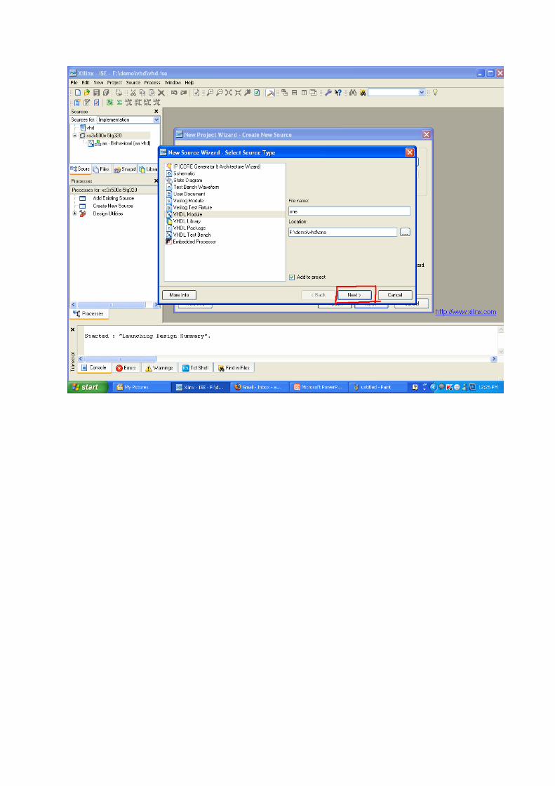
Start the ISE Software by clicking the XILINX ISE icon.Create a New Project and find the following properties displayed.
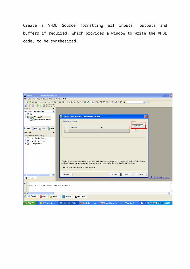
Create a VHDL Source formatting all inputs, outputs and buffers if required. which provides
a window to write the VHDL code, to be synthesized.


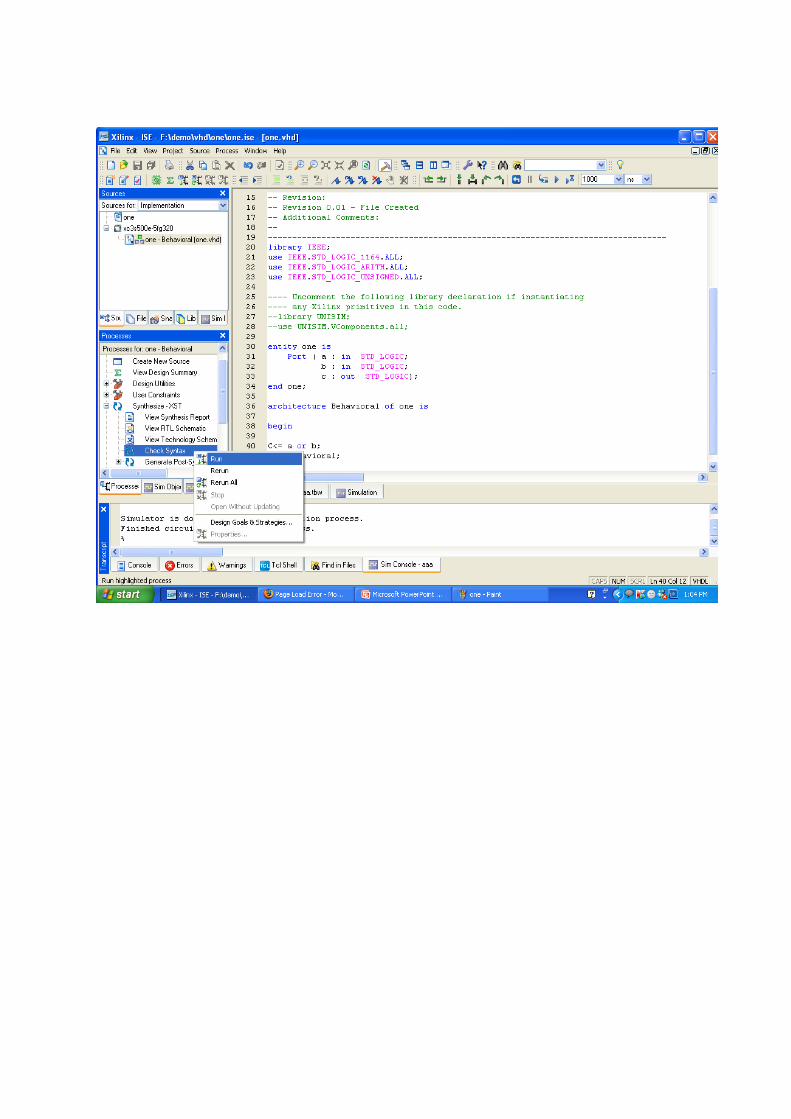
Check Syntax after finally editing the VHDL source for any errors.
After that perform the RTL and TECHNOLOGY schematic for verifying synthesis.

VHDL
VHDL is an acronym for Very High Speed Integrated Circuits Hardware
description Language. The language can be used to model a digital system at many levels
of abstraction ranging from the algorithmic level to the gate level. The complexity of the
digital system being modeled could vary from that of a simple gate to a complete digital
electronic system. The VHDL language can be regarded as an integrated amalgamation
of sequential, concurrent, net list and waveform generation languages and timing
specifications.
4.1.1 History of VHDL
VHDL stands for VHSIC (Very High Speed Integrated Circuit) Hardware Description Language.
It was developed in the 1980’s as spin-off of a high-speed integrated circuit research project funded
by the US department of defense. During the VHSIC program, researchers were confronted with the
daunting task of describing circuits of enormous scale (for their time) and of managing very large
circuit design problems that involved multiple teams of engineers. With only gate-level tools
available, it soon became clear that more structured design methods and tools would be needed.
To meet this challenge, teams of engineers from three companies - IBM, Texas Instruments
and Intermetrics — were contracted by the department of defense to complete the specification and
implementation of a new language based design description method. The first publicly available
version of VHDL, version 7.2 was released in 1985. In 1986, the IEEE was presented with a proposal
to standardize the language, which it did in 1987 and academic representatives. The resulting
standard, IEEE 1076—1987 is the basis for virtually every simulation and synthesis product sold
today. An enhanced and updated version of the language, IEEE 1076-1993, was released in 1994,

and VHDL tool vendors have been responding by adding these new language features to their
products.
Although IEEE standard 1076 defines the complete VHDL language, there are aspects of the
language that make it difficult to write completely portable design descriptions (description that can
be simulated identically using different vendor’s tools). The problem stems from the fact that VHDL
supports many abstract data types, but it does not address the simple problem of characterizing
different signal strengths or commonly used simulation conditions such as unknowns and high
impedances. Soon after IEEE 1076-1987 [3] was adopted, simulator companies began enhancing
VHDL with new non-standard types to allow their customers to accurately simulate complex
electronics circuits. This caused problems because design descriptions entered into one simulator
were often incompatible with another with other environments. VHDL was quickly becoming a non-
standard.
To get around the problem of non-standard data types, an IEEE committee adopted another
standard. This standard numbered 1164, defines a standard package (a VHDL feature that allows
commonly used declaration to be collected into an external library) containing definition for a
standard nine-value data type. This standard data type is called standard logic, and the IELL 1164
package is often referred to as the standard logic package.
The IEEN 1076-1987 and IEEE 1164 standards together form the complete VHDL
standard in widest use today (IEEE 1076-1993 is slowly working its way into the VHDL
mainstream, but it does not add significant number of features for synthesis users).
In the search for a standard design and documentation tool for the Very High Speed
Integrated Circuits (VHSIC) program the United States Department of Defense (DOD) in the summer
of 1981 sponsored a workshop on HDLs at Woods Hole, Massachusetts. The conclusion of the
workshop was the need for a standard language, and the features that might be required by such a
standard in 1983.DoD established requirements for a standard VHSIC hardware description
language(VHDL), based on the recommendation of the “Woods Hole” workshop. A contract for the
development of the VHDL language, its environment, and its software was awarded to IBM, Texas
instruments and Intermetrics. VHDL 2.0 was released only six months after the project began. The
language was significantly improved hereafter and other shortcomings were corrected leading to the
release of VHDL 6.0. In 1985 this significant developments led to the release of VHDL 6.0. In 1985
these significant development led to the release of VHDL 7.2 language reference manual. This was
later on developed as IEEE 1076/A VHDL language reference manual.
Efforts for defining the new version of VHDL stated in 1990 by a ream of volunteers working
under the IEEE DASC (Design Automation Standards committee). In October of 1992, a new VHDL’93
was completed and was released for review. After minor modifications, this new version was
approved by the VHDL balloting group members and became the new VHDL language standard. The
present VHDL standard is formally referred as VHDL 1076-1993.
4.1.2 Levels of abstraction (Styles)
VHDL supports many possible styles of design description. These styles differ primarily in
how closely they relate to the underlying hardware. When we speak of the different styles of VHDL,
then, we are really talking about the differing levels of abstraction possible using the language. To
give an example, it is possible to describe a counter circuit in a number of ways. At the lowest level
of abstraction, you could use VHDL's hierarchy features to connect a sequence of predefined logic
gates and flip-flips to form a counter circuit.
Fig. 4.1 Levels of abstraction
In a behavioral description, the concept of time may be expressed precisely, with actual
delays between related events, or may simply be an ordering of operations that are expressed
sequentially. When you are writing VHDL for input to synthesis tools, you may use behavioral
statements in VHDL to imply that there are registers in your circuit. It is unlikely, however, that your
synthesis tool will be capable of creating precisely the same behavior in actual circuitry as you have
defined in the language.

The highest level of abstraction supported in VHDL is called the behavioral level of
abstraction. When creating a behavioral description of a circuit, you will describe your circuit in
terms of its operation over time. The concept of time is the critical distinction between behavioral
descriptions of circuits and lower-level descriptions.
If you are familiar with event-driven software programming languages then writing behavior
level VHDL will not seem like anything new. Just like a programming language, you will be writing
one or more small programs that operate sequentially and communicate with one another through
their interfaces. The only difference between behavior-level VHDL and a software programming
language such as Visual Basic is the underlying execution platform: in the case of Visual Basic, it is
the Windows operating system; in the case of VHDL, it is a simulator.
An alternate design method, in which a circuit design problem is segmented into registers
and combinational input logic, is what is often called the dataflow level of abstraction. Dataflow is an
intermediate level of abstraction that allows the drudgery of combinational logic to be hidden while
the more important parts of the circuit, the registers, are more completely specified.
There are some drawbacks to using a purely dataflow method of design in VHDL. First, there
are no built-in registers in VHDL; the language was designed to be general-purpose, and VHDL’s
designers on its behavioral aspects placed the emphasis. If you are going to write VHDL at the
dataflow level of abstraction, then you must first create behavioral descriptions of the register
elements that you will be using in your design. These elements must be provided in the form of
components or in the form of subprograms.
But for hardware designers, for whom it can be difficult to relate the sequential descriptions
and operation of behavioral VHDL with the hardware that is being described, using the dataflow
level of abstraction can make quite a lot of sense. Using dataflow, it can be easier to relate a design
description to actual hardware devices.
The dataflow and behavior levels of abstraction are used to describe circuits in terms of their
logical function. There is a third style of VHDL that is used to combine such descriptions together
into a larger, hierarchical circuit description.
Structural VHDL allows you to encapsulate one part of a design description as a re-usable
component. Structural VHDL can be thought of as being analogous to a textual schematic, or as a
textual block diagram for higher-level design.

4.1.3 Need for VHDL
The complex and laborious manual procedures for the design of the hardware have paved the way for the development of languages for high –level description of the digital system. This high-level description can serve as documentation for the part as well as an entry point into the design process. The high level description can be processed through various boards, or gate array using the synthesis tools of Hardware Description language us such a language. VHDL was designed as a solution to provide an integrated design and documentation to communicate design data between various levels of abstractions.
4.1.4 Advantages of VHDLVHDL allows quick description and synthesis of circuits of 5, 10, 20 thousand gates. It also
provides the following capabilities. The following are the major advantages of VHDL over other
hardware description languages:
• Power and flexibility VHDL has powerful language constructs which allows code description of
complex control logic.
• Device independent design VHDL creates design that fits into many device architecture and it
also permits multiple styles of design description.
• Portability VHDL’s portability permits the design description to be used on different simulators
and synthesis tools. Thus VHDL design descriptions can be used in multiple projects.
• ASIC migration The efficiency of VHDL allows design to be synthesized on a CPLD or an FPGA.
Sometimes the code can be used with the ASIC.
• Quick time to market and low cost VHDL and programmable logic pair together facilitate speedy
design process. VHDL permits designs to be described quickly.
Programmable logic eliminates expenses and facilitates quick design iterations
• The language can be used as a communication medium between different Computer
Aided Design (CAD) and Computer Aided Engineering (CAE) tools.
• The language supports hierarchy, i.e., a digital system can be modeled as a set of
interconnected components; each component, in turn, can be modeled as a set of
interconnected subcomponents.
• The language supports flexible design methodologies: Top-Down, Bottom- Up, or Mixed.

• The language is technology independent and hence the same behavior model can be
synthesized into different vendor libraries.
• Various digital modeling techniques such as finite-state machine descriptions,
algorithmic descriptions and Boolean equations can be modeled using the language.
declared in the interface to the package.
4.1.7.2 Architecture
Every entity in a VHDL design description must be bound with a corresponding architecture.
The architecture describes the actual function of the entity to which it is bound. Using the schematic
as a metaphor, you can think of the architecture as being roughly analogous to a lower-level
schematic pointed to by the higher-level functional block symbol.
The second part of a minimal VHDL source file is the architecture declaration. Every entity
declaration you write must be accompanied by at least one corresponding architecture.
The architecture declaration begins with a unique name, followed by the name of the entity
to which the architecture is bound. Within the architecture declaration is found the actual functional
description of our comparator. There are many ways to describe combinational logic functions in
VHDL.
• Formal Definition
A body associated with an entity declaration to describe the internal organization or
operation of a design entity. An architecture body is used to describe the behavior, data
flow or structure of a design entity:
• Simplified syntax
Architecture architecture-name of entity-name is
Architecture-declarations
Begin
Concurrent-statements

End [architecture] [architecture-name];
• Description
Architecture assigned to an entity describes internal relationship between input and output
ports of the entity. It contains of two parts: declarations and concurrent statements. First
(declarative) part of architecture may contain declarations of types, signals, constants, subprograms
(functions and procedures), components and groups.
Concurrent statements in the architecture body define the relationship between inputs and
outputs. This relationship can be specified using different types of statements: Concurrent signal
assignment, process statement, component instantiation, and concurrent procedure call, generate
statement, concurrent assertion statement, and block statement. It can be writing in different
styles: structural, dataflow, behavioral (functional) or mixed.
The description of a structural body is based on component instantiation and generates
statements. It allows creating hierarchical projects, from simple gates to very complex components,
describing entire subsystems. The Connections among components are realized through ports.
The Dataflow description is built with concurrent signal assignment statements. Each of the
statements can be activated when any of its input signals changes its value.
The architecture body describes only the expected functionality (behavior) of the circuit,
without any direct indication as to the hard ware implementation. Such description consists only of
one or more processes, each of which contains sequential statements. The Architecture body may
contain statements that define both behavior and structure of the circuit at the same time. Such
architecture description is called mixed.
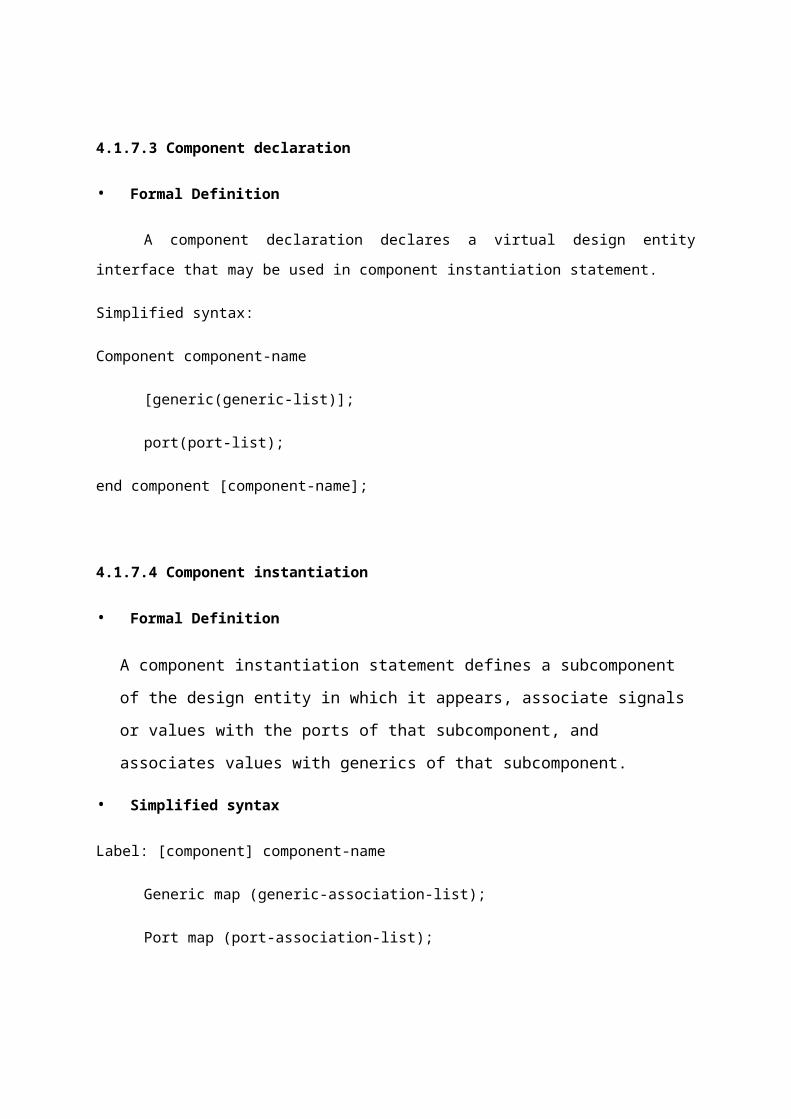
4.1.7.3 Component declaration
• Formal Definition

A component declaration declares a virtual design entity interface that may be used in
component instantiation statement.
Simplified syntax:
Component component-name
[generic(generic-list)];
port(port-list);
end component [component-name];
4.1.7.4 Component instantiation
• Formal Definition
A component instantiation statement defines a subcomponent of the design entity in
which it appears, associate signals or values with the ports of that subcomponent, and
associates values with generics of that subcomponent.
• Simplified syntax
Label: [component] component-name
Generic map (generic-association-list);
Port map (port-association-list);
4.1.7.5 Configuration declaration
• Formal Definition
A configuration is a construct that defines how component instances in a given block are
bound to design entities in order to describe how design entities are put together to form a
complete design.
• Simplified syntax
Configuration configuration-name of entity-name is
Configuration declarations.
For architecture-name
For instance-label: component-name
Use entity library-name. Entity-name (arch-name);
End for;
end for;
end configuration-name;
4.1.7.6 Configuration instantiation
• Formal Definition
A component instantiation statement defines a subcomponent of the design entity in which
it appears, associates signals or value with the ports of that subcomponent, and associates values
with generics of that subcomponent.
• Simplified syntax
Label: Configuration configuration-name
Generic map (generic-association-list);
Port map (port-association-list);
4.1.7.7 Package
• Formal Definition
A package declaration defines the interface to a package.
• Simplified syntax
Package package-name is
Package –declarations
End [package] package-name;
Package body
• Formal Definition
A package body defines the bodies of subprograms and the values of deferred constants
declared in the interface to the package.
Simplified syntax:
Package body package-name is
Package-body-declarations
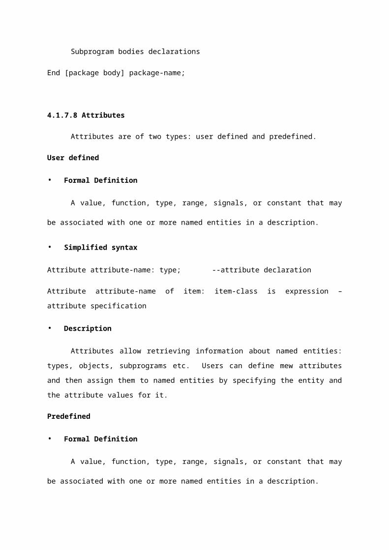
Subprogram bodies declarations
End [package body] package-name;
4.1.7.8 Attributes
Attributes are of two types: user defined and predefined.
User defined
• Formal Definition
A value, function, type, range, signals, or constant that may be associated with one or more
named entities in a description.
• Simplified syntax
Attribute attribute-name: type; --attribute declaration
Attribute attribute-name of item: item-class is expression –attribute specification
• Description
Attributes allow retrieving information about named entities: types, objects, subprograms
etc. Users can define mew attributes and then assign them to named entities by specifying the
entity and the attribute values for it.
Predefined
• Formal Definition
A value, function, type, range, signals, or constant that may be associated with one or more
named entities in a description.
Simplified syntax: object’s attribute-name
4.1.7.9 Process statement
• Formal Definition
A process statement defines an independent sequential process representing the behavior
of some portion of the design
Simplified syntax:
[process-label:] process [(sensitivity-list)];
Process-declarations
begin
Sequential-statements
end process [process-label];
4.1.7.10 Function
• Formal Definition
A function call is a subprogram of the form of an expression that returns a value.
• Simplified syntax
Function function name(parameters) return type -- function declaration
Function function-name(parameters) return type is --- function definition.
Begin
Sequential statements
End [function] function-name;
4.1.7.11 Port
• Formal DefinitionA channel for dynamic communication between a block and its environment.
Simplified syntax:
Port (port-declaration, port-declaration,-----);
----port declarations:
Port-signal-name: in port-signal-type: =initial-value
Port-signal-name: out port-signal-type: =initial-value
Port-signal-name: in out port-signal-type: =initial-value
Port-signal-name: buffer port-signal-type: =initial-value
Port-signal-name: linkage port-signal-type: =initial-value
4.1.7.12 Sensitivity list
• Formal Definition
A list of signals a process is sensitive to.
Simplified syntax:
(Signal-name, signal-name, ---)
Formal Definition
4.1.7.13 Standard logic
• Formal Definition
A nine-value resolved logic type.
Std-logic is not a part of the VHDL standard. It is defined in IEEE Std 1164.
Simplified syntax:
Type std-ulogic is (‘U’, -- Uninitialized
‘X’, -- Forcing Unknown
‘0’, -- Forcing 0
‘1’, -- Forcing 1
‘Z’ -- High Impedance
‘W’--Weak Unknown
‘L’--Weak 1
‘-‘--Don’t Care);
Type std-ulogic-vector is array (natural range <>) of std-ulogic
Function resolved (s: std-ulogic-vector) return std-ulogic;
Subtype std-logic is resolved std-ulogic;
4.1.8 Data Types
There are many data types available in VHDL. VHDL allows data to be represented in terms
of high-level data types. These data types can represent individual wires in a circuit, or can represent
collections of wires using a concept called an array.
The preceding description of the comparator circuit used the data types bit and bit vector
for its inputs and outputs. The bit data type (bit vector is simply an array of bits) values of '1' and '0'
are the only possible values for the bit data type. Every data type in VHDL has a defined set of
values, and a defined set of valid operations. Type checking is strict, so it is not possible, for example,
to directly assign the value of an integer data type to a bit vector data type. (There are ways to get
around this restriction, using what are called type conversion functions.) VHDL is rich language with
many different data types.
The most common data types are listed below:
Bit: a 1-bit value representing a wire. (Note: IEEE standard 1164 defines a 9-valued
replacement for bit called std_logic.)
Bit vector: an array of bits. (Replaced by std_logic_vector in IEEE 1164.)
Boolean: a True/False value.
Integer: a signed integer value, typically implemented as a 32-bit data type.
Real: a floating-point value.
Enumerated: used to create custom data types.
Record: used to append multiple data types as a collection.
Array: can be used to create single or multiple dimension arrays.
Access: similar to pointers in C or Pascal.
file: used to read and write disk files. Useful for simulation.
Physical: used to represent values such as time, voltage, etc. using symbolic units of
measure (such as 'ns' or 'ma').
4.1.9 Packages and Package Bodies
A VHDL package declaration is identified by the package keyword, and is used to collect
commonly used declarations for use globally among different design units. You can think of a
package as being a common storage area, one used to store such things as type declarations,
constants, and global subprograms.
A package can consist of two basic parts: a package declaration and an optional package
body. Package declarations can contain the following types of statements:
Type and subtype declarations
Constant declarations
Global signal declarations
Function and procedure declarations
Attribute specifications
File declarations
Component declarations
Alias declarations
Disconnect specifications
Use clauses
Items appearing within a package declaration can be made visible to other design units
through the use of a use statement.
If the package contains declarations of subprograms (functions or procedures) or defines
one or more deferred constants (constants whose value is not given), then a package body is
required in addition to the package declaration. A package body must have the same name as its
corresponding package declaration, but can be located anywhere in the design.
The relationship between a package and package body is somewhat akin to the relationship
between an entity and its corresponding architecture. While the package declaration provides the
information needed to use the items defined within it (the parameter list for a global procedure, or
the name of a defined type or subtype), the actual behavior of such things as procedures and
functions must be specified within package bodies.

CHAPTER: 3
IMPLIMENTATION:
ROM core is organized as NOR gates— pull_dwon transistors of NOR determine
programming.
Erasable ROMs require special processing that is not typically available.
ROMs on digital ICs are generally mask programmed— placement of pull-downs determines ROM contents.
FUNCTIONAL IMPLEMENTATION:
Can implement multi-input/multi-output logic functions inside of ROM. Data outputs are the logic functions and the address lines are the logic function
inputs. We create a ROM Table to store the logic functions. When an input (or address) is presented, the value stored in the specified memory
location appears at the data outputs. Each data output represents the correct value for its logic function.
--------------------------------------------------------------

CHAPTER-4
PROGRAM:
library ieee;
use ieee.std_logic_1164.all;
use ieee.std_logic_arith.all;
use ieee.std_logic_unsigned.all;
entity MEMORY_CORE is
port( Clock : in std_logic;
Reset : in std_logic;
Enable : in std_logic;
Read : in std_logic;
Address : in std_logic_vector(4 downto 0);
Data_out: out std_logic_vector(7 downto 0)
);
end MEMORY_CORE;
--------------------------------------------------------------
architecture Behav of MEMORY_CORE is
type MEMORY_CORE_Array is array (0 to 31)
of std_logic_vector(7 downto 0);
constant Content: MEMORY_CORE_Array := (
0 => "00000001", -- Suppose MEMORY_CORE has
1 => "00000010", -- prestored value
2 => "00000011", -- like this table
3 => "00000100", --
4 => "00000101", --
5 => "00000110", --
6 => "00000111", --
7 => "00001000", --
8 => "00001001", --
9 => "00001010", --
10 => "00001011", --
11 => "00001100", --
12 => "00001101", --
13 => "00001110", --
14 => "00001111", --
OTHERS => "11111111" --
);
begin
process(Clock, Reset, Read, Address)
begin
if( Reset = '1' ) then
Data_out <= "ZZZZZZZZ";
elsif( Clock'event and Clock = '1' ) then
if Enable = '1' then
if( Read = '1' ) then

Data_out <= Content(conv_integer(Address));
else
Data_out <= "ZZZZZZZZ";
end if;
end if;
end if;
end process;
end Behav;
--------------------------------------------------------------

CHAPTER: 5
SPECIFICATIONS:
more speed less power low cost
MODULES:
FDE-D flip flop with enable. FDPE-D flip flop with preset ROM buffer. ROM Buffer
PROPERTIES:
Spartan 3e Xc3s 100e VQ 100
Memory size:
32 Locations in each consists of 8 bit.
Advantages:
The operation is performed in a very less time. It works at a speed of 4.347ns.
Disadvantages:
Its takes more time for manufacturing process.