VLBI2010 Analog Electronics Seminar - ivscc.gsfc.nasa.gov · • 12m antenna with 50% efficiency...
26
VLBI2010 Analog Electronics Seminar Christopher Beaudoin MIT Haystack Observatory
Transcript of VLBI2010 Analog Electronics Seminar - ivscc.gsfc.nasa.gov · • 12m antenna with 50% efficiency...
VLBI2010 Analog Electronics Seminar
Christopher BeaudoinMIT Haystack Observatory

Outline
1. VLBI2010 Receiver Requirements– System level requirements– Hardware requirements– Knowledge requirements
2. Receiver Cascade Overview
3. 20K Cryogenic Frontend– Feeds– LNAs
4. Signal Link Considerations– RF Frontend to Backend Downlink – Reference Up/Down link
5. RF to IF Downconversion– UpDown Converter
6. Next-generation Calibration Systems– Phase/Noise Calibration– Reference Cable Calibration

VLBI2010 Receiver RequirementsSystem Level Requirements
• Initial Receiver Requirements outlined in IVS Progress Report “Design Aspects of the VLBI2010 System”
– ftp://ivscc.gsfc.nasa.gov/pub/misc/V2C/PR-V2C_090417.pdf
• 1mm Long Term position accuracy
• Backward Compatibility with Legacy S/X band systems

• 12m antenna with 50% efficiency and Front-end Noise Temperature: 50K
• Feed– Frequency range: 2-14 GHz– Dual polarization, low cross polarization leakage– Uniform illumination of antenna– Minimal phase center variation
• Current Bandwidth Requirements– Four 1 GHz bands per polarization– Achieves 2 ps delay precision– With 2-bit sampling, total data recorder rate requirement is 32 Gbps
VLBI2010 Receiver RequirementsHardware Requirements

• Next-generation Phase/Noise Calibration system– Phase cal critical for removing hardware-related delays (knowledge to <1ps)– Noise cal needed for source structure corrections (knowledge TBD)
• May also be needed for hardware amplitude calibration
• Next-generation Cable Calibration System– Determine reference delay variations with antenna pointing (knowledge to < 0.5ps)– Determine reference delay due to temperature over long distances (knowledge to < 0.5 ps)
VLBI2010 Receiver RequirementsKnowledge Requirements

Receiver Cascade Overview
20K Cryogenic Frontend
Phase/Noise Cal CouplerLNA
5K 5K
40K Antenna Temperature
0.004K Source Temperature
12m Antenna 50% Eff
RF Frontend to Backend Downlink
RF to IF Downconversion
2-14 GHz feed
Band A, Pol 0
Band A, Pol 1
Band B, Pol 0
Band B, Pol 1
Band C, Pol 0
Band C, Pol 1
Band D, Pol 0
Band D, Pol 1
Eight 1 GHz IF signals
Reference Up/Downlink
5 MHz MASER
Antenna Section
Calibration Generator
5 M
Hz Ref Dly Cal
Reference Delay Calibrator
Control Room Section

20K Cryogenic Front-endFeeds
• IVS has not officially made feed recommendation yet
• Two primary candidate feeds have hardware realizations– Eleven Antenna Chalmers University of Technology (CUT)– Quadridge Feed Horn (QRFH) California Insititute of Technology (Caltech)
• Eleven Antenna– Developed by Per-Simon Kildal, Jian Yang at CUT
• QRFH Antenna– Developed by Sander Weinreb, Ahmed Akigray at CalTech

20K Cryogenic Front-endFeeds – Eleven Antenna
• Eleven Antenna– Log-periodic design– Designed primarily for antenna systems with 0.3-0.4 F/D– Currently requires 8 LNAs for operation
• Possibly four in the near future
– Phase cal injection pre-LNA is complicated
1
Σ
2
-3
Σ- 3
∆
50Ω Load
-3
Σ- 3
∆
50ΩLoad
LNA LNA
LNALNA
50ΩLoad
50ΩLoad
50ΩLoad
50ΩLoad
Dewar Output
Bottom of Feed
SMA
SMASMA
SMA
SM
A
SM
A
SM
A
SM
A
3
21
43
2 1
4 1166871166
95
#240DPAD4
#127DPAD3
#128DPAD2
#239DPAD1
Matched Cable Lengths
Matched Cable
Lengths

20K Cryogenic Front-endFeeds – Eleven Antenna
• Return Loss– Lower quantities indicates better
performance. Should be < 10 dB– Rough measure of how much quasar signal
is reflected back into space– Poor return loss can negatively influence
frontend temperature
• Feed Efficiency– How well feed performs on the reflector
antenna system– Calculated assuming 100° prime focus
reflector capture angle– Doesn’t include efficiency losses due to
electrical losses or struct scattering

20K Cryogenic Front-endFeeds - QRFH
• QRFH Antenna– Horn design– Design can accommodate a wide range of optics – Currently requires 2 LNAs (1 for each
polarization) for operation– Phase cal injection pre-LNA is possible

20K Cryogenic Front-endFeeds - QRFH
• Return Loss– Lower quantities indicates better
performance. Should be < 10 dB– Rough measure of how much quasar signal
is reflected back into space– Poor return loss can negatively influence
frontend temperature
• Feed Efficiency– How well feed performs on the reflector
antenna system– Calculated assuming Patriot 12m optics– Doesn’t include efficiency losses due to
electrical losses or struct scattering

20K Cryogenic Front-endLNAs
• VLBI2010 places a very stringent requirement on antenna sensitivity– 50K noise temperature over 2-14 GHz– 40K sky contribution + 10K front-end = 50K Tsys
– 10K front-end noise temperature over more than a decade bandwidth!– Front-end will undoubtedly need to be cryogenic
• Unlike S/X systems, entire bandwidth is processed by single device
• Dynamic range must be considered very carefully in light of RFI
• Required low noise amplifier hardware is not commercially available

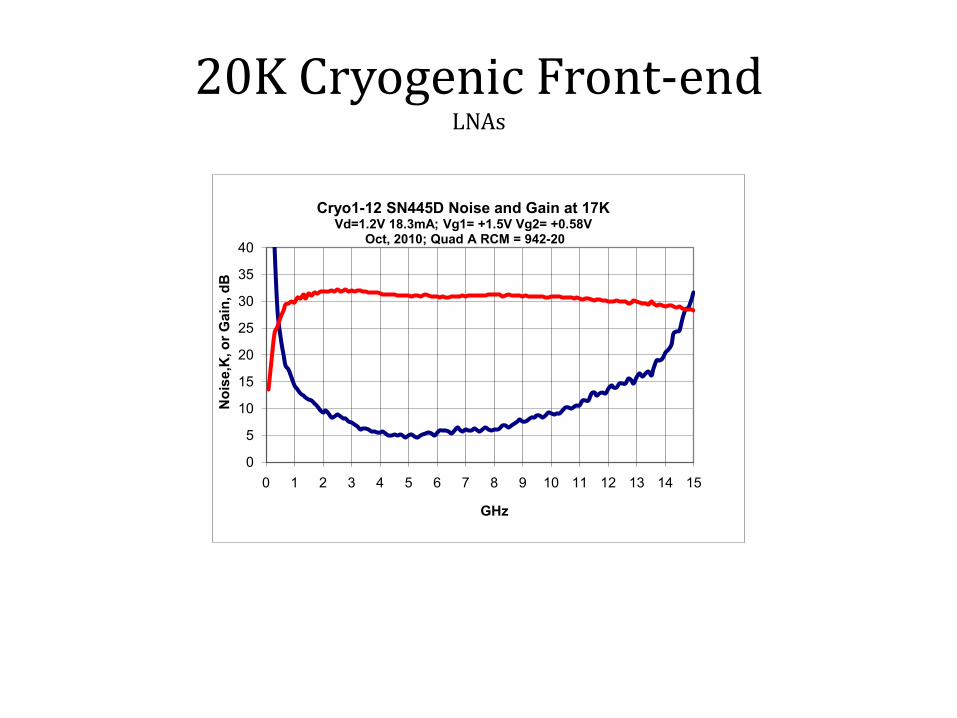
20K Cryogenic Front-endLNAs
• Only known hardware source are in academic fab from Caltech
– Model Number CRYO1-12– Designed by Sandy Weinreb– MMICs are fabricated by NGST– ITAR restricition lifted - can now be exported from US– Noise temperature ~12K at 12 GHz and 20K physical temperature– VERY sensitive to ESD, take ESD precautions when handling!– Installation of diode limiters highly recommended– Bias regulator also required to properly operate the device– Input 1dB compression ~-40 dBm,
• Total input power should not exceed -50 dBm to avoid fringe losses
• Easily saturated by RFI
20K Cryogenic Front-endLNAs
0
5
10
15
20
25
30
35
40
0 1 2 3 4 5 6 7 8 9 10 11 12 13 14 15
Noi
se,K
, or G
ain,
dB
GHz
Cryo1-12 SN445D Noise and Gain at 17K Vd=1.2V 18.3mA; Vg1= +1.5V Vg2= +0.58V
Oct, 2010; Quad A RCM = 942-20

20K Cryogenic Front-endDewar/Cryostat - Internal Construction
• Cryostat Dimensions– Feed Recess: 22.2 mm– 70K Shield Thickness: 3.2mm
Outer Wall
Inner WallIR Filter: 16 layers of 25-µm-thick Teflon film separated by a mesh of fine tissue/veil
70K Station
20K Station

20K Cryogenic Front-endDewar/Cryostat – External Construction
SMA/Microwave Connections0.3 mm Mylar vacuum window
RefrigeratorVacuum Valve
• Cryostat Dimensions– Outer Wall Diameter: 279 mm– Inner Wall Diameter: 254 mm– Outer Wall Length: 420 mm

Signal Link ConsiderationsRF Frontend to Backend Downlink
• Two primary means of downlinking the RF signals1. Coaxial Cable2. RF over Fiber Optics
• Coax cable not terribly feasible as a low-loss 2-14 GHz link for VLBI2010– Cable must be able to withstand constant flexing as antenna pointing varies– Cable loss calculators can be misleading– Be sure cable manufacturer specifications rate cable at required operating frequency
• Alternative is to downconvert RF IF in the antenna section– Requires more hardware near the front-end in unstable weather conditions– Low-loss, cost-effective cables to 1.5 GHz are commercially available (e.g. LMR-400UF - 20dB/100m)
• RF over fiber – Limited space in frontend– Extremely long cable runs (e.g. 4km at Arecibo)– 0.25 dB/ km over fiber vs. 200 dB/km (LMR400 at 1.5 GHz)– Transmitter receiver pair cost: $5600; 4km FC/APC duplex single-mode fiber $4300 USD fiber.com
Signal Link ConsiderationsRF Frontend to Backend Downlink
• RF over fiber (cont.) – Device dynamic range should be carefully considered in light of RFI– See PhotonicsInc website for detailed specifications:
• http://www.photonicsinc.com/pdfs/1600_10L/PSI-1600_series.pdf

Signal Link ConsiderationsReference Up/Down link
• Primary purpose is to convey the MASER reference to the frontend– Phase cal generator– Synthesizer for downconverter (if DC occurs in antenna section)
• May be necessary to monitor (downlink) reference cable delay variations1. Delay variations due to antenna pointing
• should be assessed for a particular antenna
2. Possible delay variations with temperature• LMR-400UF TempCo = 9ppm/K• In 4 km of cable delay variation is 120 ps/K
3. See slides on next-generation cable calibration system
• Coaxial Cable or Fiber?– Among fiber manufacturers, units only support frequencies as low as 45 MHz– Fiber not a problem if 50-100 MHz MASER reference is available– Coaxial cable offers good thermal stability and is time tested
• LMR-400 best suited for 5 MHz distribution• LMR-240 best suited for 10 MHz distribution

RF to IF Downconversion• Purpose is to translate RF signals to frequencies/bandwidths that can be managed by
the analog to digital converter (ADC) in the digital backend (DBE).
• For state-of-the-art DBEs, these signals are:– 512 MHz in bandwidth (can be 1 GHz in case of DBBC)– iADC can currently handle 0-512, 512-1024, and 1024-1536 MHz– DBBC can handle above bands as well as 1-1024, 1024-2048, and 2048-3072 MHz
• Some VLBI2010 Receiver Backend Nomenclature:– A VLBI2010 receiver “band” is half the DBE’s ADC sampler rate (i.e. Nyquist zone bandwidth)– In contrast to “band” as defined in Mark4/BBCs used in legacy systems– What is referred to as a “band” in MK4 is referred to as a “channel” for VLBI2010 receiver’s– Strictly speaking, what is referred to as a singleband delay in Fourfit would be referred to as a single-
channel delay for VLBI2010 receivers.

x4Luff SynthesizerProgrammable5.25-8.25 GHz
RF to IF DownconversionUpDown Converter
• UpDown Converter VLBI2010 operational specifications– RF input range: 1-13 GHz– IF output range: 0.5-2.5 GHz– IF output levels commandable with 30 dB programmable attenuator– Minimum local oscillator step size: 400 kHz– Nominal input power: -30 dBm/12 GHz– Control via front panel or RS232 interface– Design has been developed for 2-18 GHz operation
• Functional behavior
1-13 GHz
fRF f
1st LO23-33 GHz
21 GHz
f
1st LO
21 GHz
22.5 GHz 2nd LO2 GHz BW
12 GHz
fIF
0.5-2.5 GHz
Cavity Filter
1.5 GHz
fRF + 22.5 – 4fluff = fIF
2nd LO 1st LO

Next-generation Calibration SystemsPhase/Noise Calibration
• Phase calibration is required to remove hardware-related delay components from observed delays. Knowledge requirement set to 0.5ps
• Implementation in broadband geodetic observing will differ somewhat
• S/X band geodetic VLBI systems incorporate phase calibration generator based on tunnel diode technology
– diodes are no longer available
• Alan E.E. Rogers developed next generation phase calibration generator circuit
– Overcomes shortcoming of tunnel diodes– Uses high speed digital logic IC technology– Enhances spectral flatness of the phase calibration
spectrum
Reference Input Phase Cal Signal Output
High Speed Digital Logic Gate

Next-generation Calibration SystemsPhase/Noise Calibration
• In S/X band receivers , S and X band phase cal levels could be set independently
• VLBI2010 receivers will incorporate a single cascade to receive the entire 2-14 GHz frequency band.
– This drives the flatness required of the next-generation phase calibration spectrum – Balance between low and high frequency amplitudes should accommodate calibration performance– Reference signal should be +13 dBm to achieve optimal flatness
• Point of phase cal injection still remains somewhat ambiguous. This ambiguity will likely be resolved once a feed is adopted for VLBI2010
– Radiated phase cal injection could prove problematic for correcting the broadband observable– Coupler injection is more reliable but could be complicated by combiner network
Voltage Limiter Edge Sharpening Differentiator (-) Pulse Gating
Gate Timing
Reference Source
Phase Cal Signal

Next-generation Calibration SystemsPhase/Noise Calibration
Bias Tee
Maser Reference
Input
H/V Outputs to Dewar
Phase Cal Generator
Pulse Gating Switch
Noise Cal Generator
• Noise calibration required for knowledge of receiver gain stability and noise temperature– Most stringent requirement imposed by source structure corrections (TBD)– Less strigentl requirement based on receiver sensitivity (< 10%) and gain calibration (< 1 dB)
• Honeywell taken over development of phase/noise calibration solution – Replacement of Micronetics noise source with Noisecom device– Broadband programmable attenuator also planned for additional capability

Next-generation Calibration SystemsPhase/Noise Calibration
• Other feature of total phase/noise calibration solution• Incorporates RF gaskets and other techniques to mitigate leakage• Phase cal signal leakage levels < -180 dBm• Also incorporates thermal control capability• Maintains set temperature to 0.2° C over differential ambient temperatures in excess of 20° C
Phase Cal Generator
RF GasketNoise Source
Phase Cal + Noise Unit
Thermal Enclosure
280 mm
197
mm
190 mm
DC, Control, & Monitor
Phase Cal + Noise Outputs
5 MHz Input
Thermo-electric Heater/Cooler

Next-generation Calibration SystemsReference Cable Calibration
• The need for a cable calibration system for VLBI2010 has not been explicit• Certain cases such as Onsala where it has been a benefit• Other cases where it has introduced more noise in the delay observables
• Installation will likely be station specific but when is one needed• If reference cables delays are correlated to antenna pointing• If reference cable TempCo is sufficiently large to introduce large delay changes with modest temeprature flucutations
• Cable calibration measurement is not trivial because cables can be dispersive• TempCo in LMR-400 varies significantly between 5 and 10 MHz• If delay measurement is not performed at or near same frequency of reference, the correction may not be valid
• Must confirm that frequencies of delay observations can be related to delays at reference frequency• This relationship would ideally be linear but could be more complex – must be understood!
• Cable calibration techniques are still being investigated for VLBI2010
• Arecibo Observatory is prototyping such a system based on fiber optics• Demonstrated 0.05 ps noise in delay measurements• Uses phase delay of 1.5 GHz signal to infer delay variations of 100 MHz reference convey to frontend