VKD/CP DN 10-50 - aliaxis-ui.hu DN 10-50.pdf · Diagramma delle perdite di carico Pressure loss...
23
FORMATURA P O L I M E R I I N I E Z I O N E Valvola a sfera a 2 vie DUAL BLOCK® a comando pneumatico Pneumatically actuated 2-way ball valve DUAL BLOCK® Robinet à tournant sphérique à 2 voies DUAL BLOCK® à commande pneumatique 2-Wege-Kugelhahn DUAL BLOCK® mit Pneumatik-Antrieb VKD/CP DN 10-50
Transcript of VKD/CP DN 10-50 - aliaxis-ui.hu DN 10-50.pdf · Diagramma delle perdite di carico Pressure loss...

F O R M A T U R A
P O L I M E R II N I E Z I O N E
Valvola a sfera a 2 vie DUAL BLOCK®a comando pneumatico
Pneumatically actuated 2-way ball valve DUAL BLOCK®
Robinet à tournant sphérique à 2 voiesDUAL BLOCK® à commande pneumatique
2-Wege-Kugelhahn DUAL BLOCK®mit Pneumatik-Antrieb
VKD/CP DN 10-50

VKD/CP DN 10-50

129
VKD/CP DN 10-50
Valvola a sfera a 2vie DUAL BLOCK®a comando pneumatico
Pneumatically actua-ted 2-way ball valveDUAL BLOCK®
Robinet à tournantsphérique à 2 voiesDUAL BLOCK® à com-mande pneumatique
2-Wege-KugelhahnDUAL BLOCK® mitPneumatik-Antrieb
FIP ha sviluppato una nuova val-vola a sfera di tipo VK DUALBLOCK® per introdurre un eleva-to standard di riferimento nellaconcezione delle valvole termopla-stiche. VKD è una valvola a sferabi-ghiera a smontaggio radiale,che risponde alla più severe esi-genze richieste nelle applicazioniindustriali. Un servizio assoluta-mente privo di complicazioni è ilprincipio di base che si vuole otte-nere con la progettazione di unavalvola con queste caratteristiche.• Gamma dimensionale da d 16
mm a d 63 mm, da R3/8” a R2”• Sistema di giunzione per incol-
laggio, per filettatura e per flan-giatura
• Resistenza a pressioni di eserci-zio fino a 16 bar a 20° C; per ildettaglio vedere pagina seguen-te
• Sistema brevettato DUALBLOCK®: il nuovo sistema diblocco assicura il serraggio delleghiere anche nel caso di condi-zioni di servizio gravose come,per esempio, in presenza divibrazioni o dilatazioni termiche.
• Facile smontaggio radiale dal-l’impianto e conseguente rapidasostituzione degli O-ring e delleguarnizioni della sfera senzal’impiego di alcun attrezzo
• Sistema di tenuta SEAT-STOP,possibilità di micro-registrazionecon apposita ghiera e sistema dibloccaggio delle spinte assiali.
• Possibilità di smontaggio delletubazioni a valle con la valvolain posizione di chiusura
• Corpo attuatore in allumino trat-tato per resistere in ambientiaggressivi
• Attuatore pneumatico realizzatosu specifiche FIP.Foratura dei raccordi di alimen-tazione aria secondo le normeNAMUR.Foratura superiore per il fissag-gio accessori ed estremità supe-riore pignone secondo le normeVDI/VDE 3845
FIP has developed a new ballvalve type VK DUAL BLOCK® tointroduce an advanced standard ofreference in thermoplastic valvedesign. VKD is a (true) union lockball valve, which stands up to themost severe industrial applicationrequirements. Absolutetrouble free service is the basicprinciple to be achieved with thetrue blocked union design.• Size range from d 16 mm up to
d 63 mm and from R3/8” up toR2”
• Jointing by solvent welding,threaded or flanged connections
• Maximum working pressure: 16bar at 20° C; for full details seefollowing page
• Patented system DUALBLOCK®: the new locking devi-ce ensures the nuts are held inposition even under severe servi-ce conditions: i.e. vibration orthermal expansion
• Easy removal of the valve bodyfrom the system, allowing quickreplacement of O-rings and ballseats without additional equip-ment
• SEAT-STOP seat and seal design.Axial pipe loads block withmicro adjustment of ball seal.
• In the closed position the pipeli-ne can be disconnected dow-nstream from the valve withoutleakage
• The actuator body is made of aspecial aluminium alloy forapplications in aggressive envi-ronments
• Pneumatic actuator produced onFIP specifications.Solenoid air connections accor-ding to NAMUR standard.Top drilling for accessories faste-ning and upper shaft size accor-ding to VDI/VDE 3845 standard
FIP a développé un nouveau robi-net à tournant sphèrique de typeVK DUAL BLOCK® qui a intro-duit un niveau très haut de réfé-rence dans la conception des robi-nets thermoplastiques. VKD est unrobinet à sphère avec doubleécrou union avec blocage de sécu-rité, qui peut satisfaire la plupartdes applications industrielles. Leprincipe de base de ce nouveaurobinet a boisseau sphérique est lagarantie de sécurité d’utilisationpour la clientèle industrielle • Gamme dimensionnelle de d 16
mm à d 63 mm, de R3/8” à R2”• Jonction par collage aussi bien
que par filetage• Pression de service jusqu’à 16
bar à 20° C; pour les détails voirpage suivante
• Système breveté DUALBLOCK®: Nouveau système deblocage qui assure la conserva-tion de la position des écrousunion, même en cas de duresconditions de service: par exem-ple avec des vibrations ou dila-tation thermique.
• Démontage radiaI du corps durobinet qui permet un remplace-ment rapide des joints O-ring etdes autres garnitures, sans utili-ser aucun outil
• SEAT-STOP conception de siègeset points d’étanchéité. Emboutsavec réglage de l’étanchéité dela bille et système de blocagedes poussées axiales.
• En position fermée, le robinetpermet le démontage de l’instal-lation en aval par rapport à ladirection du flux
• Actionneur en aluminium traitérésistant aux agents agressifs
• Actionneur pneumatique réalisésur spécification technique deFIP.Perçage des raccords pour l’aird’alimentation suivant les nor-mes NAMUR.Perçage supérieur pour le fixagedes accessoires et bout supé-rieure du pignon suivant les nor-mes VDI/VDE 3845
FIP hat einen neuen Kugelhahn,die Type VK DUAL BLOCK®,entwickelt. Hiermit beginnt ein"neues Konzept" bei den thermo-plastischen Ventilen.VKD ist ein beidseitig verschraub-ter Kugelhahn, der den meistenindustriellen Anwendungengerecht wird. “Sicherheit undZuverlässigkeit“ ist dasBasisprinzip, das es zu erreichengalt. Es wurde durch dieKonstruktion der arretiertenVerschraubungen erreicht.• Größen von d 16 mm bis d 63
mm und von R 3/8” bis R 2”• Mit Klebe- oder
Gewindeanschlüssen• Der maximale Betriebsdruck
beträgt 16 bar bei 20° C.Weitere Einzelheiten auf der fol-genden Seite
• DUAL BLOCK ® patentierteSystem: die neueSperrvorrichtung hält dann dieÜberwurfmuttern unter verschie-densten Einsatzbedingungen(Vibrationen oder thermischeAusdehnung) sicher in Position.
• Der einfache Ausbau der Armaturaus dem Leitungssystem erlaubtden schnellen Wechsel von O-Ringen oder Kugelsitzen ohnezusätzliches Werkzeug
• SEAT-STOP Sitz- undDichtungskonzept: dieKugelabdichtung ist durch eineMikro-Justierung frei vonRohrleitungskräften.
• In geschlossener Stellung desKugelhahns kann die druckloseSeite der Leitung ohne Leckagegelöst werden
• Antrieb aus Alu-Speziallegierungfür Einsatz in aggressiverUmgebung
• Pneumatik-Antrieb nach FIP-Spezificakation. Bohrung derSpeiseanschlussstucke nachNAMUR-Normen.Obere Bohrung zur Fixierungvon Zubehör und oberesRitzelende nach VDI/VDE 3845Normen
l dati del presente prospetto sono for-niti in buona fede. La FIP non si assu-me alcuna responsabilità su quei datinon direttamente derivati da normeinternazionali. La FIP si riserva diapportarvi qualsiasi modifica.
The data given in this leaflet are offe-red in good faith. No liability can beaccepted concerning technical datathat are not directly covered by reco-gnized international Standards. FIPreserves the right to carry out anymodification to the products shown inthis leaflet.
Les données contenues dans cette bro-chure sont fournies en bonne foi. FIPn’assume aucune responsabilité pourles données qui ne dérivent pas direc-tement des normes internationales. FIPgarde le droit d’apporter toute modifi-cation aux produits présentés danscette brochure.
Alle Daten dieser Druckschrift wurdennach bestem Wissen angegeben,jedoch besteht keine Verbindlichkeit,sofern sie nicht direkt internationalenNormen entnommen wurden. DieÄnderung von Maßen oderAusführungen bleibt FIP vorbehalten.

130
VKD/CP DN 10-50
LEGENDA
d Rohraußendurchmesserin mm
DN Rohrnennweite inmm
R Gewinde (DIN 2999,T1)
PN Nenndruck; höchstzu-lässigerBetriebsdruck inbar, bei 20° C Wasser
g Gewicht in GrammU Anzahl der
Schraubenlöchers Wandstärke, mmSDR Standard Dimension
Ratio = d/sPVC-U Polyvinylchlorid hart
PP-H PolypropylenHomopolimerisat
PVC-C Polyvinylchloridnachchloriert
PVDF Polyvinylidenfluorid
EPDM Ethylenpropylen-dienelastomer
FPM Fluorelastomer
PTFE PolytetraflourethylenPE PolyethylenDA doppelt wirkendSA einfach wirkendPOM Polyoxymethylen
d diametro nominaleesterno del tubo inmm
DN diametro nominaleinterno in mm
R dimensione nominaledella filettatura in pollici
PN pressione nominale inbar (pressione max diesercizio a 20°C inacqua)
g peso in grammiU numero dei foris spessore tubo in mm
SDR standard dimensionratio = d/s
PVC-U cloruro di polivinilerigido
PP-H polipropilene omopo-limero
PVC-C cloruro di polivinilesurclorato
PVDF polifluoruro di vinili-dene
EPDM elastomero etilenepropilene
FPM fluoroelastomero
PTFE politetrafluoroetilenePE polietileneDA doppio effettoSA semplice effettoPOM resina poliacetalica
d nominal outside dia-meter of the pipe inmm
DN nominal internal dia-meter in mm
R nominal size of thre-ads in inches
PN nominal pressure inbar (max. workingpressure at 20°C -water)
g weight in gramsU number of holess wall thickness, mm
SDR standard dimensionratio = d/s
U-PVC unplasticized polyvinylchloride
PP-H polypropylene homo-polymer
PVC-C chlorinated polyvinylchloride
PVDF polyvinylidene fluoride
EPDM ethylene propylenerubber
FPM vinylidene fluoriderubber
PTFE polytetrafluoroethylenePE polyethyleneDA double actingSA single actingPOM Polyoxymethylene
d diamètre extérieurnominal du tube enmm
DN diamètre intérieurnominal du tube enmm PN
R dimension nominalede filetage en pouces
PN pression nominale enbar (pression de servi-ce max à 20°C- eau)
g poids en grammesU nombre de trouss épaisseur du tube, mm
SDR standard dimensionratio = d/s
PVC-U polychlorure de vinylenon plastifié
PP-H polypropylènehomopolymère
PVC-C polychlorure de vinylesurchloré
PVDF polyfluorure de vinyli-dène
EPDM élastomère ethylènepropylène
FPM fluorélastomère devinylidène
PTFE polytétrafluoroéthylènePE polyethylèneDA double effetSA simple effetPOM Résine Polyacetal

131
VKD/CP DN 10-50
Per coefficiente di flusso kv100 siintende la portata Q in litri al minutodi acqua a 20°C che genera unaperdita di carico ∆p= 1 bar per unadeterminata posizione della valvola.I valori kv100 indicati in tabella si inten-dono per valvola completamenteaperta.
kv100 is the number of litres perminute of water at a temperature of20°C that will flow through the valvewith ∆p= 1 bar differential-pressure ata specified position.The kv100 values shown in the table arecalculated with the valve completelyopen.
kv100 est le nombre de litres d’eau,à une température de 20°C, quis’écoule en une minute dans unevanne pour une position donnée avecune pression différentielle ∆p de 1 bar.Les valeurs kv100 indiquées sur la tablesont évaluées lorsque le robinet estentièrement ouvert
Der kv100 -Wert nennt denurchsatz in l/min für Wasser bei20°C und einem ∆p von 1 bar beivöllig geöffnetem Ventil.
2bar1614121086420
-40 °C140-20 20 40 60 80 1000
PP-H
120
PVC-U PVC-C PVDF
1
3
1
2
pres
sione
di e
serc
izio
- wor
king
pre
ssur
epr
essio
n de
ser
vice
- Bet
riebs
druc
k
temperatura di esercizio - working temperaturetempérature de service - Betriebstemperatur
Variazione della pressione in fun-zione della temperatura per acquao fluidi non pericolosi nei confrontidei quali il materiale è classificatoCHIMICAMENTE RESISTENTE.In altri casi è richiesta un’adegua-ta diminuzione della pressionenominale PN.(25 anni con fattore di sicurezza).
Pressure/temperature rating forwater and harmless fluids towhich the material is RESISTANT.In other cases a reduction of therated PN is required.(25 years with safety factor).
Variation de la pression enfonction de la température pourl’eau et les fluides non agressifspour lequel le matériau est consi-déré CHIMIQUEMENT RESISTANT.Pour les outres cas une diminutiondu PN est nécessaire.(25 années avec facteur de sécuri-té inclus).
Druck/Temperatur-Diagramm fürWasser und ungefährliche Mediengegen die das MaterialBESTÄNDIG ist.In allen anderen Fällen ist eineentsprechende Reduzierung derDruckstufe erforderlich.(Unter Berücksichtigung desSicherheitsfaktors für 25 Jahre).
Diagramma delle perdite di carico Pressure loss chart Table de perte de charge Druckverlust-Diagramm
3 Coefficiente di flusso kv100 Flow coefficient kv100 Coefficient de débit kv100 kv100 –Wert
2015
200
161080
dDN
kv100
2520
385
3225
770
4032
1100
6350
3400
5040
1750
bar
1
0,1
0,01
0,001
DN 15
DN 20
100 l/min1000 10000101
DN 25
DN 32
DN 40
DN 50
DN 10
perd
ita d
i car
ico -
pres
sure
lost
- pe
rte d
e ch
arge
- Dr
uckv
erlu
st
portata - flow rate- débit - Durchflußmenge
Dati Tecnici
Technical Data
Données Techniques
TechnischeDaten

132
VKD/CP DN 10-50
Dimensioni Dimensions Dimensions Dimensionen
La FIP produce una gamma di val-vole a sfera, i cui attacchi sono inaccordo con le seguenti norme:Incollaggio PVC-U:ISO727, EN 1452, DIN 8063,BS4346/1, ASTM 2467/76a.Accoppiabili con tubi secondoISO161/1, EN 1452, DIN8062,NF T54-016, BS3506, BS3505,ASTM D1785/76.Incollaggio PVC-C:ISO 727, EN ISO 15493,ASTM F439, accoppiabili con tubisecondo EN ISO 15493,DIN 8079/8080,ASTM D 1785/76.Saldatura nel bicchiere PP-H:DIN 16962. Da accoppiare contubi secondo ISO 3609,DIN 8077, UNI 8318, BS 4991.Saldatura nel bicchiere PVDF:ISO DIS 10931.Da accoppiare con tubi secondoISO DIS 10931/2.Filettatura: UNI-ISO 228/1,DIN 2999, BS21,ASA ANSI B1.20.1Flangiatura: ISO 2084, UNI 7442,DIN 8063, ASA ANSI B.16.5 150.
FIP produce a complete range ofball valves whose coupling complywith the following standards:Solvent welding U-PVC:ISO727, EN 1452, DIN 8063,BS4346/1, ASTM 2467/76a.Coupling to pipes complying withISO161/1, EN 1452, DIN8062,NF T54-016, BS3506, BS3505,ASTM D1785/76.Solvent welding C-PVC:ISO727, EN ISO 15493,ASTM F439, coupling to pipescomplying with EN ISO 15493,DIN 8079/8080,ASTM D 1785/76.Socket fusion PP-H: DIN 16962.For coupling to pipes complyingwith: ISO 3609, DIN 8077,UNI 8318, BS 4991.Socket fusion PVDF:ISO DIS 10931 For coupling to pipes complyingwith: ISO DIS 10931/2.Threaded coupling:UNI-ISO 228/1, DIN 2999, BS21,ASA ANSI B1.20.1 Flanged couplings: ISO 2084UNI 7442/75, DIN 8063,ASA ANSI B.16.5 150.
La FIP a réalisé une gammecomplète de robinets à tournantsphérique dont les embouts sontconformes aux normes suivantesEncollage PVC-U:ISO727, EN 1452, DIN 8063,BS4346/1, ASTM 2467/76a.Assemblés à des tubes conformesaux normes ISO161/1,EN 1452, DIN8062, NF T54-016,BS3506,BS3505,ASTM D1785/76.Encollage PVC-C:ISO 727, EN ISO15493,ASTM F439,assemblés avec des tubes selonEN ISO 15493, DIN 8079/8080,ASTM D 1785/76.Soudure par fusion PP-H:DIN 16962.Assemblés à des tubes conformesaux normes: ISO 3609, DIN 8077,UNI 8318, BS 4991.Soudure par fusion PVDF:ISO DIS 10931Assemblés à des tubes conformesaux normes: ISO DIS 10931/2.Filetage: UNI-ISO 228/1,DIN 2999, BS21,ASA ANSI B1.20.1Brides: ISO 2084, UNI 7442/75,DIN 8063, ASA ANSI B.16.5 150.
Die Kugelhahnreihe entsprichtmit ihren Anschlußmöglichkeitenfolgenden Normen:Klebeanschluß PVC-U:ISO727, EN 1452, DIN 8063,BS4346/1, ASTM 2467/76a.Für Rohre nach ISO161/1,EN 1452, DIN8062, NF T54-016,BS3506, BS3505,ASTM D1785/76.Klebeanschluß PVC-C:ISO 727, EN ISO 15493,ASTM F439, für Rohre nach EN ISO 15493, DIN 8079/8080,ASTM D 1785/76.Schweißanschluß PP-H:DIN 16962. Für Verbindungen mitRohren:ISO 3609, DIN 8077, UNI 8318,BS 4991.Schweißanschluß PVDF:ISO DIS 10931. Für Verbindungenmit Rohren: ISO DIS 10931/2Gewindeverbindung:UNI-ISO 228/1, DIN 2999, BS21,ASA ANSI B1.20.1Flanschanschluß: ISO 2084,UNI 7442/75, DIN 8063,ASA ANSI B.16.5 150
DN
10152025324050
G
20202020202020
E1
60,560,5
7575868686
B1
2929
34,539465262
B
135135161161200207217
B2
5858
73,57497
104114
g PP-H
(SA)
1150114514711551245626583107
g PVC
(SA)
1215120515831691266929013518
g PVC-C
(SA)
1228122216031723270029883611
g PVDF
(SA)
1260125516431803279131263911
(DA)
1155114514731581246927013318
(DA)
1090108513611441225624582907
(DA)
1168116214931613250027883411
(DA)
1200119515331693259129263711

133
VKD/CP DN 10-50
VKDIV/CP VKDIM/CP VKDIC/CP VKDIF/CP
VALVOLA A DUE VIE DUAL BLOCKcon attacchi femmina metrici in PVC-U,PP-H,PVC-C,PVDF
2-WAY BALL VALVE DUAL BLOCKwith metric series plain femaleends in U-PVC,PP-H,C-PVC,PVDF
ROBINET À 2 VOIS DUAL BLOCKavec embouts femelles série métri-que en PVC-U,PP-H,PVC-C,PVDF
2-WEGE KUGELHAHN DUALBLOCK mit Muffe nach ISO ausPVC-U,PP-H,PVC-C,PVDF
d
16202532405063
H1
656570788893
111
H
103103115128146164199
DN
10152025324050
*PN
16161616161616
E
545465738698
122
H2
160160138138
155,5155,5155,5
Ra
1/8"1/8"1/8"1/8"1/4"1/4"1/4"
LPP-HPVDF
14151719232428
ZPP-HPVDF
74,5738290
100117144
PVCPVC-C
14161922263138
PVCPVC-C
7571778494
102123
VKDDV/CP VKDDM/CP VKDDC/CP VKDDF/CP
VALVOLA A DUE VIE DUAL BLOCKcon attacchi maschio, serie metricaPVC-U,PP-H,PVC-C,PVDF
2-WAY BALL VALVE DUAL BLOCKwith metric series plain male endsU-PVC,PP-H,C-PVC,PVDF
ROBINET À 2 VOIS DUAL BLOCKavec embouts mâle, série métriquePVC-U,PP-H,PVC-C,PVDF
2-WEGE KUGELHAHN DUALBLOCK mit Stutze nach ISOPVC-U,PP-H,PVC-C,PVDF
d
16202532405063
H1
656570788893
111
H
149124144154174194224
DN
10152025324050
*PN
16161616161616
E
545465738698
122
H2
160160138138
155,5155,5155,5
Ra
1/8"1/8"1/8"1/8"1/4"1/4"1/4"
*PP-H PN 10 bar
*PP-H PN 10 bar
LPP-HPVDF
-161820222529
PVC-UPVC-C
14161922263138
134
VKD/CP DN 10-50
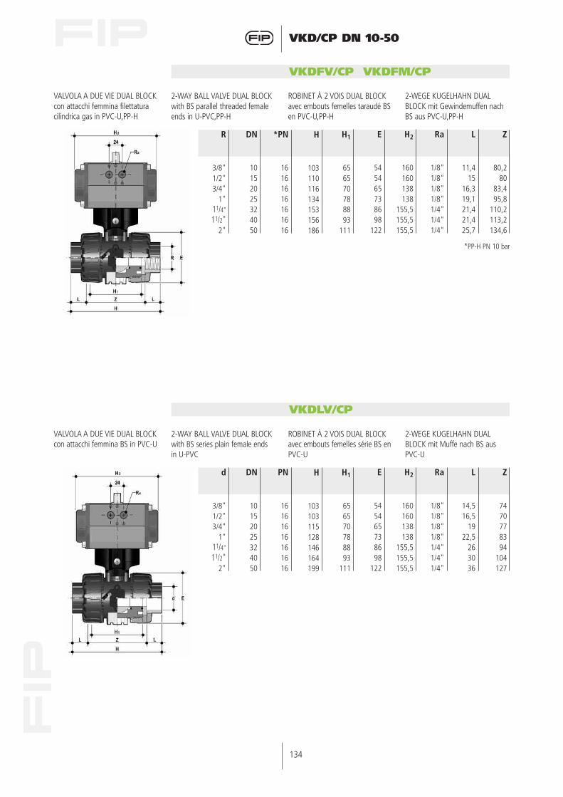
VKDFV/CP VKDFM/CP
VALVOLA A DUE VIE DUAL BLOCKcon attacchi femmina filettaturacilindrica gas in PVC-U,PP-H
2-WAY BALL VALVE DUAL BLOCKwith BS parallel threaded femaleends in U-PVC,PP-H
ROBINET À 2 VOIS DUAL BLOCKavec embouts femelles taraudé BSen PVC-U,PP-H
2-WEGE KUGELHAHN DUALBLOCK mit Gewindemuffen nachBS aus PVC-U,PP-H
R
3/8"1/2"3/4"
1"11/4”
11/2"2"
H1
656570788893
111
H
103110116134153156186
DN
10152025324050
*PN
16161616161616
E
545465738698
122
H2
160160138138
155,5155,5155,5
Ra
1/8"1/8"1/8"1/8"1/4"1/4"1/4"
L
11,415
16,319,121,421,425,7
Z
80,280
83,495,8
110,2113,2134,6
VKDLV/CP
VALVOLA A DUE VIE DUAL BLOCKcon attacchi femmina BS in PVC-U
2-WAY BALL VALVE DUAL BLOCKwith BS series plain female endsin U-PVC
ROBINET À 2 VOIS DUAL BLOCKavec embouts femelles série BS en PVC-U
2-WEGE KUGELHAHN DUALBLOCK mit Muffe nach BS ausPVC-U
d
3/8"1/2"3/4"
1"11/4”
11/2"2"
H1
656570788893
111
H
103103115128146164199
DN
10152025324050
PN
16161616161616
E
545465738698
122
H2
160160138138
155,5155,5155,5
Ra
1/8"1/8"1/8"1/8"1/4"1/4"1/4"
L
14,516,5
1922,5
263036
Z
7470778394
104127
*PP-H PN 10 bar
135
VKD/CP DN 10-50
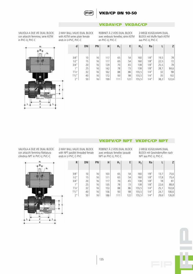
VKDAV/CP VKDAC/CP
VALVOLA A DUE VIE DUAL BLOCKcon attacchi femmina, serie ASTMin PVC-U, PVC-C
2-WAY BALL VALVE DUAL BLOCKwith ASTM series plain femaleends in U-PVC, PVC-C
ROBINET À 2 VOIS DUAL BLOCKavec embouts femelles, série ASTMen PVC-U, PVC-C
2-WEGE KUGELHAHN DUALBLOCK mit Muffe Nach ASTMaus PVC-U, PVC-C
d
3/8"1/2"3/4"
1"11/4”
11/2"2"
H1
656570788893
111
H
117117129142162172199
DN
10152025324050
PN
16161616161616
E
545465738698
122
H2
160160138138
155,5155,5155,5
Ra
1/8"1/8"1/8"1/8"1/4"1/4"1/4"
L
19,522,525,528,7
3235
38,2
Z
787278
84,698
102122,6
R
3/8"1/2"3/4"
1"11/4”
11/2"2"
H1
656570788893
111
H
103111117135153156186
DN
10152025324050
PN
16161616161616
E
545465738698
122
H2
160160138138
155,5155,5155,5
Ra
1/8"1/8"1/8"1/8"1/4"1/4"1/4"
L
13,717,8
1822,625,124,729,6
Z
75,675,4
8188,8
102,8106,6126,8
VKDFV/CP NPT VKDFC/CP NPT
VALVOLA A DUE VIE DUAL BLOCKcon attacchi femmina filettaturacilindrica NPT in PVC-U, PVC-C
2-WAY BALL VALVE DUAL BLOCKwith NPT parallel threaded femaleends in U-PVC, C-PVC
ROBINET À 2 VOIS DUAL BLOCKavec embouts femelles taraudéNPT en PVC-U, PVC-C
2-WEGE KUGELHAHN DUALBLOCK mit Gewindemuffen nachNPT aus PVC-U, PVC-C

136
VKD/CP DN 10-50
VKDJV/CP
VALVOLA A DUE VIE DUAL BLOCKcon attacchi femmina JIS in PVC-U
2-WAY BALL VALVE DUAL BLOCKwith JIS series plain female endsin U-PVC
ROBINET À 2 VOIS DUAL BLOCKavec embouts femelles série JISen PVC-U
2-WEGE KUGELHAHN DUALBLOCK mit Muffe nach JIS ausPVC-U
d
1/2"3/4"
1"11/4”
11/2"2"
H1
6570788893
111
H
131147164182212248
DN
152025324050
PN
161616161616
E
5465738698
122
H2
160138138
155,5155,5155,5
Ra
1/8"1/8"1/8"1/4"1/4"1/4"
L
303540445563
Z
71778494
102122
VKDGV/CP
VALVOLA A DUE VIE DUAL BLOCKcon attacchi femmina filettaturaJIS in PVC-U
2-WAY BALL VALVE DUAL BLOCKwith JIS threaded female ends inU-PVC
ROBINET À 2 VOIS DUAL BLOCKavec embouts femelles taraudé JISen PVC-U
2-WEGE KUGELHAHN DUALBLOCK mit Gewindemuffen nachJIS aus PVC-U
R
1/2"3/4"
1"11/4”
11/2"2"
H1
6570788893
111
H
103115128146164199
DN
152025324050
PN
161616161616
E
5465738698
122
H2
160138138
155,5155,5155,5
Ra
1/8"1/8"1/8"1/4"1/4"1/4"
L
161922252631
Z
71778496
112137

137
VKD/CP DN 10-50
VKDOV/CP VKDOM/CP VKDOC/CP VKDOF/CP
ISO-DINVALVOLA A 2 VIE DUAL BLOCKcon flange libere foratura UNI2223 PN10/16, DIN 2501Scartamento secondo EN 558-1 in PVC-U, PP-H, PVC-C, PVDF
ISO-DIN2-WAY BALL VALVE DUAL BLOCKwith DIN 8063, DIN 2501 backingrings.Face to face acc. to EN 558-1 inU-PVC, PP-H, PVC-C, PVDF
ISO-DINROBINET À 2 VOIS DUAL BLOCKavec brides libres DIN 8063, DIN2501Longueur hors-tout EN 558-1 enPVC-U, PP-H, PVC-C, PVDF
ISO-DIN2-WEGE KUGELHAHN DUALBLOCK mit Flanschen, Nach DIN8063 Teil 4, DIN 2501, Baulangenach DIN 3441 Teil 2, EN 558-1aus PVC-U, PP-H, PVC-C, PVDF
d
202532405063
H
130150160180200230
DN
152025324050
*PN
161616161616
H1
6570788893
111
H2
160138138
155,5155,5155,5
Ra
1/8"1/8"1/8"1/4"1/4"1/4"
F
657585
100110125
f
141414181818
U
444444
VKDOV/CP VKDOM/CP VKDOC/CP VKDOF/CP
ANSIVALVOLA A 2 VIE DUAL BLOCKcon flange libere foratura ANSI150 #RFScartamento secondo EN 558-1 in PVC-U, PP-H, PVC-C, PVDF
ANSI2-WAY BALL VALVE DUAL BLOCKwith ANSI 150 #RF backing rings Face to face acc. to EN 558-1 inU-PVC, PP-H, PVC-C, PVDF
ANSIROBINET À 2 VOIS DUAL BLOCKavec brides libres ANSI 150 #RF Longueur hors-tout EN 558-1 enPVC-U, PP-H, PVC-C, PVDF
ANSI2-WEGE KUGELHAHN DUALBLOCK mit Flanschen, nach ANSI150 #RF Baulange nach EN 558-1 ausU-PVC, PP-H, PVC-C, PVDF
*PP-H PN 10 bar
d
1/2"3/4"
1"11/4”
11/2"2"
H
------
DN
152025324050
*PN
161616161616
H1
6570788893
111
H2
160138138
155,5155,5155,5
Ra
1/8"1/8"1/8"1/4"1/4"1/4"
F
60,369,979,488,998,4
120,7
f
15,915,915,915,915,919,1
U
444444
*PP-H PN 10 bar

138
VKD/CP DN 10-50
Accessori Accessories Accessoires Zubehör
CVDE-CVDM
CONNETTORI IN PE - PP-H codololungo, per giunzioni con manicottielettrici o testa a testa SDR 11PN 16
END CONNECTOR IN PE - PP-Hlong spigot, for electro fusion orbutt weld SDR 11 PN 16
EMBOUTS MALES EN PE poursoudure par électrofusion oubout-à-bout SDR 11 PN 16
ANSCHLUßTEILE MIT LANGEMSTUTZEN AUS PE - PP-Hzur Heizwendelmuffen- oderHeizelementstumpf- SchweißungSDR 11 PN 16
d
202532405063
H
175210224243261293
DN
152025324050
PN
161616161616
H1
6570788893
111
E
5465738698
122
H2
160138138
155,5155,5155,5
Ra
1/8"1/8"1/8"1/4"1/4"1/4"
139
VKD/CP DN 10-50
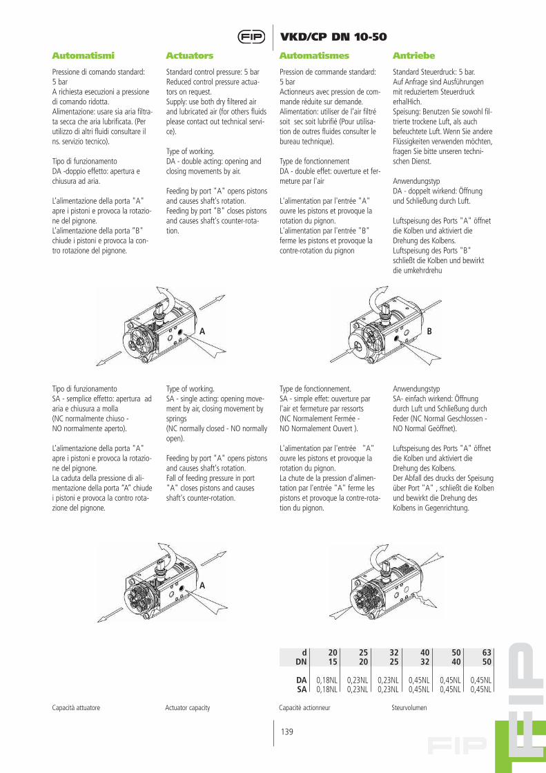
Automatismi Actuators Automatismes Antriebe
Pressione di comando standard:5 barA richiesta esecuzioni a pressionedi comando ridotta.Alimentazione: usare sia aria filtra-ta secca che aria lubrificata. (Perutilizzo di altri fluidi consultare ilns. servizio tecnico).
Tipo di funzionamentoDA -doppio effetto: apertura echiusura ad aria.
L’alimentazione della porta "A"apre i pistoni e provoca la rotazio-ne del pignone.L’alimentazione della porta “B"chiude i pistoni e provoca la con-tro rotazione del pignone.
Standard control pressure: 5 barReduced control pressure actua-tors on request.Supply: use both dry filtered airand lubricated air (for others fluidsplease contact out technical servi-ce).
Type of working.DA - double acting: opening andclosing movements by air.
Feeding by port "A" opens pistonsand causes shaft's rotation.Feeding by port "B" closes pistonsand causes shaft's counter-rota-tion.
Pression de commande standard:5 barActionneurs avec pression de com-mande réduite sur demande.Alimentation: utiliser de l’air filtrésoit sec soit lubrifié (Pour utilisa-tion de outres fluides consulter lebureau technique).
Type de fonctionnementDA - double effet: ouverture et fer-meture par l'air
L'alimentation par l'entrée "A"ouvre les pistons et provoque larotation du pignon.L'alimentation par l'entrée "B"ferme les pistons et provoque lacontre-rotation du pignon
Standard Steuerdruck: 5 bar.Auf Anfrage sind Ausführungenmit reduziertem SteuerdruckerhalHich.Speisung: Benutzen Sie sowohl fil-trierte trockene Luft, als auchbefeuchtete Luft. Wenn Sie andereFlüssigkeiten verwenden möchten,fragen Sie bitte unseren techni-schen Dienst.
AnwendungstypDA - doppelt wirkend: Öffnungund Schließung durch Luft.
Luftspeisung des Ports "A" öffnetdie Kolben und aktiviert dieDrehung des Kolbens.Luftspeisung des Ports "B"schließt die Kolben und bewirktdie umkehrdrehu
Tipo di funzionamentoSA - semplice effetto: apertura adaria e chiusura a molla (NC normalmente chiuso - NO normalmente aperto).
L’alimentazione della porta "A"apre i pistoni e provoca la rotazio-ne del pignone.La caduta della pressione di ali-mentazione della porta “A” chiudei pistoni e provoca la contro rota-zione del pignone.
Type of working.SA - single acting: opening move-ment by air, closing movement bysprings(NC normally closed - NO normallyopen).
Feeding by port "A" opens pistonsand causes shaft's rotation.Fall of feeding pressure in port"A" closes pistons and causesshaft's counter-rotation.
Type de fonctionnement.SA - simple effet: ouverture parl'air et fermeture par ressorts (NC Normalement Fermée - NO Normalement Ouvert ).
L'alimentation par l'entrée "A"ouvre les pistons et provoque larotation du pignon.La chute de la pression d'alimen-tation par l'entrée "A" ferme lespistons et provoque la contre-rota-tion du pignon.
AnwendungstypSA- einfach wirkend: Öffnungdurch Luft und Schließung durchFeder (NC Normal Geschlossen -NO Normal Geöffnet).
Luftspeisung des Ports "A" öffnetdie Kolben und aktiviert dieDrehung des Kolbens.Der Abfall des drucks der Speisungüber Port "A" ‚ schließt die Kolbenund bewirkt die Drehung desKolbens in Gegenrichtung.
2015
0,18NL0,18NL
dDN
DASA
2520
0,23NL0,23NL
3225
0,23NL0,23NL
4032
0,45NL0,45NL
6350
0,45NL0,45NL
5040
0,45NL0,45NL
Capacità attuatore Actuator capacity Capacitè actionneur Steurvolumen
BA
A

140
VKD/CP DN 10-50
Accessori Accessories Accessoires Zubehör
3MS
Box microinterruttoridi fine corsa
Limit switch box Boîtier de fin course Endschalterboxen
ELETTROMECCANICI (Fig.1)Portata: 250V - 16 AProtezione box: IP65Temperatura: -20°/ +70°Pressacavo: M20x1,5INDUTTIVI-Tipo: PNP (3fili) (Fig.2)Tensione: 10-30 V DCCorrente: 0-100mAProtezione box: IP65Protezione finecorsa:IP67Temperatura: -20°/+80°CPressacavo: M20x1,5-Tipo: NAMUR (Fig.3)Tensione: 8 V DCCorrente: 1-3 mAProtezione box: IP65Protezione finecorsa:IP67Temperatura: -20°/+100°CPressacavo: M20x1,5
ELETTROMECHANICAL (Fig.1)Rate: 250V - 16 ABox Protection: IP65Temperature: -20°/ +70°Cable-gland: M20x1,5PROXIMITY-Type: PNP (3wires) (Fig.2)Voltage: 10-30 V DCCurrent: 0-100mABox Protection: IP65Switch protection: IP67Temperature: -20°/+80°CCable-gland: M20x1,5-Type: NAMUR (Fig.3)Voltage: 8 V DCCurrent: 1-3 mABox Protection: IP65Switch protection: IP67Temperature: -20°/+100°CCable-gland: M20x1,5
ELETTROMECANIQUE (Fig.1)Tension- charge: 250V - 16 ABox Protection: IP65Température: -20°/ +70°Raccordement électrique: M20x1,5INDUCTIFS-Version: PNP (3wires) (Fig.2)Tension: 10-30 V DCCourant: 0-100mABox protection: IP65Fin course protection: IP67Température: -20°/+80°CRaccordement électrique: M20x1,5-Version: NAMUR (Fig.3)Tension: 8 V DCCourant: 1-3 mABox Protection: IP65Fin course protection: IP67Température: -20°/+100°CRaccordement électrique:M20x1,5.
ELETTROMECHANISCHEN (Fig.1)Spannung: 250V - 16 ASchutzart Gehäuse: IP65Temperatur: -20°/ +70°Verschraubung: M20x1,5INDUKTIVEN-Typ: PNP (3wires) (Fig.2)Spannung: 10-30 V DCStromaufnahme: 0-100mASchutzart Gehäuse: IP65Schutzart Schalter: IP67Temperatur: -20°/+80°CVerschraubung: M20x1,5-Typ: NAMUR (Fig.3)Spannung: 8 V DCStromaufnahme: 1-3 mA Schutzart Gehäuse: IP65Schutzart Schalter: IP67Temperatur: -20°/+100°CVerschraubung: M20x1,5.

141
VKD/CP DN 10-50
2EV
Elettrovalvola pilota 3-5/2 vie.Tensioni:24, 48, 110, 230 V AC12, 24 V CC.Protezione: IP 65Connessioni pneumatiche: G 1/4”Esecuzioni a montaggio diretto oin batteria.Versioni speciali a richiesta
Pilot solenoid valve 3-5/2 ways.Voltage:24, 48,110, 230 V AC12, 24 V DCProtection: IP65Pneumatic connections: G 1/4”Direct or rack mounting.Special versions on request
Vanne à solénoïde pilote 3-5/2voies.Voltage:24, 48,110, 230 V AC12, 24 V DCProtection: IP65Air alimentation: G 1/4”Pour le montage direct ou en bat-terie.Spéciales versions sur demande
3-5/2 Wege Vorsteuerventil.Spannungen:24, 48,110, 230 V AC12, 24 V DC.Schutzart: IP65Luft Anschluß: G 1/4”Einzelmontage oderBlockmontage.Spezial Version auf Anfrage.
3PG
Posizionatore pneumatico ed elet-tropneumaticoSegnale di comando 3-15 psi o 4-20mA.Protezione: IP 65Temperatura: -10°/+50°CConnessioni pneumatiche: G 1/4”Portata nominale: 400 Nl/minVersioni speciali a richiesta
Pneumatic and ElectropneumaticpositionerInput signal 3-15 psi or 4-20 mA.Protection: IP65Temperature: -10°/+50°CPneumatic connections: G 1/4”Nominal flow: 400 Nl/minSpecial versions on request
Positionneur pneumatique et élec-tropneumatiqueSignal de commande 3-15 psi ou4-20mA.Protection: IP65Température: -10°/+50°CAir alimentation: G 1/4”Débit nominal : 400 Nl/minSpéciales versions sur demande
Pneumatischer und elektropneu-matischer PositionsreglerEingangssignal 3-15 psi oder 4-20mA.Schutzart: IP65Temperatur: -10°/+50°CLuft Anschluß: G 1/4”Nomineller Durchfluß: 400 Nl/minSpezial Version auf Anfrage.
5/2
3/2
PMKD
d
16202532405063
DN
10152025324050
A
30303030404040
B
86868686
122122122
C
20202020303030
C1
46464646727272
C2
67,567,567,567,5102102102
F
6,56,56,56,56,56,56,5
f
5,35,35,35,36,36,36,3
f1
5,55,55,55,56,56,56,5
S
5555666
Piastrina di montaggio a muro Platine de montage BefestigungsplatteMounting plate

142
VKD/CP DN 10-50
Staffaggio e supportazione
Valve bracketingand supporting
Fixation et supportage
Kugelhahn-Halterung undBefestigung
Tutte le valvole, sia manuali chemotorizzate, necessitano in molteapplicazioni di essere supportatemediante staffe o supporti al finedi proteggere tratti di tubazionead esse collegati dall’azione dicarichi concentrati.Questi supporti devono esserein grado di resistere sia al pesoproprio della valvola, sia alle solle-citazioni generate dalla valvolastessa durante le fasi di aperturae chiusura.La serie di valvole VKD è dotata disupporti integrati che permettonoun ancoraggio diretto sul corpovalvola senza bisogno di ulterioricomponenti.Si ricorda che, vincolando lavalvola, essa viene ad agire comepunto fisso di ancoraggio, percui viene ad essere sottoposta aicarichi terminali delle tubazioni.Specialmente ove siano previstiripetuti cicli termici, occorrerà pre-vedere di scaricare la dilatazionetermica su altre parti dell’impiantoin modo da evitare pericolosisovraccarichi sui componenti dellavalvola.Per le installazioni a muro o apannello è possibile utilizzare laapposita piastrina di fissaggioPMKD, fornita come accessorio,che va fissata precedentementealla valvola.La piastrina PMKD serve ancheper allineare la valvola VKD con ifermatubi FIP tipo ZIKM (Fig. 1) eper allineare valvole di misurediverse.dentemente alla valvola.
Tous les robinets, manuels oumotorisés doivent être maintenus etpeuvent constituer des points fixes.Les efforts de charge supplémentai-re ne sont ainsi pas supportés parla tuyauterie.Ces supports doivent être en mesu-re de résister aussi bien au poidspropre du robinet qu’aux sollicita-tions engendrées par le robinet lui-même durant les phases d’ouvertu-re ou de fermeture. Toutes les van-nes VKD sont équipées d’un systè-me de fixation intégré sur le corpsde la vanne qui peut être fixé à lastructure portante avec des vis etdes écrous standards.Il faut noter qu’avec l’utilisation deces supports, le robinet agit commepoint fixe d’ancrage, raison pourlaquelle il peut être soumis auxcharges terminales des tubes.Particulièrement lorsque que l’on setrouve en présence de cycles ther-miques répétés, il faut prévoir dedécharger la dilatation thermiquesur d’autres parties de l’installation,de façon à éviter de dangereusessurcharges sur les composants durobinet.Pour les installations à mur ou àpanneau il est possible employerles appositif piastres de fixagePMKD (fournies comme accessoires)qui doivent être fixées d’abord à lavanne.La platine PMKD permet aussi d’ali-gner la vanne VKD avec les supportdes tubes ZIKM (fig.1) ainsi qued’aligner des vannes de dimensionsdifférentes.
Die Montage des Kugelhahnsmuss eine sichere Einbindung indas Rohrleitungssystem gewährlei-sten.Die Befestigung des Kugelhahnsmuss das Eigengewicht derArmatur, sowie aus dem Betriebheraus resultierende Spannungensicher übertragen können. Ausdiesem Grunde wurde eine kom-plette neue, schnell und sichermontierbare integrierteBefestigungskonzeption entwic-kelt.Die am Kugelhahn integrierteneuartige Befestigungsplatte,kann mittels Standardschraubenund Muttern an derUnterkonstruktion befestigt wer-den.Für die Wandinstallation kann diePMKD Montageplatte (17,18,19),die als Zubehör verfügbar ist, ver-wendet werden. Die Platte ist vorder Befestigung an der Wand, amBoden der Halterung anzubringen.PMKD Platte erlaubt die VKDKugelhahn Fluchtung mit den FIPRohrklemmen ZIKM (Fig.1). PMKDPlatte erlaubt auch verschiedeneMaße Kugelhähnen Fluchtung.
In some applications manual oractuated valves must be suppor-ted by simple hangers or anchors.Supports must be capable ofwithstanding weight loads as wellas the stresses transmittedthrough the valve body during ser-vice operations.All VKD valves are therefore provi-ded with an integrated support onthe valve body for a simple andquick anchoring.Caution must be taken whenusing these support systemsbecause the ball valve acts as apipe anchor and all thermal endloads developed by adjacent pipescould damage the valve compo-nents under condition of largevariation in operating temperatu-re. Systems should be designed toaccommodate pipes expansionand contraction.For wall installation it’s possible touse the dedicate PMKD mountingplate available as an accessory.The plate has to be fastened tothe bottom valve bracket beforethe wall fixation.The PMKD plate allows the ali-gnment with FIP ZIKM pipe clips(Fig.1) and permit the axial ali-gnment different sizes VKD valves.
d
16202532405063
DN
10152025324050
B
31,531,5
4040505060
H
27273030353540
L
20202020303030
*J
M4 x 6M4 x 6M4 x 6M4 x 6
M6 x 10M6 x 10M6 x 10
Fig. 1
* Con boccole di staffaggio * With Bracketing bushes * Avec Ecrous d’ancrage * Mit Gewindebuchsen

143
VKD/CP DN 10-50
Installazione sull’impianto
Connection to thesystem
Montage sur l’installation
Einbau in eineLeitung
Prima di procedere all’installazio-ne seguire attentamente le istru-zioni di montaggio:1) Verificare che le tubazioni a cui
deve essere collegata la valvolasiano allineate in modo da evi-tare sforzi meccanici sulle con-nessioni filettate della stessa.
2) Svitare le ghiere (13) e inserirlesui tratti di tubo.
3) Procedere all’incollaggio o sal-datura o avvitamento dei mani-cotti (12) sui tratti di tubo.
4) Applicare sul corpo valvolacome indicato in figura 2 ilsistema di blocco ghiereDUAL BLOCK ® (16) fornitonella confezione.DUAL BLOCK ® è il nuovosistema brevettato svilup-pato da FIP che dà la pos-sibilità di bloccare, in unaposizione prefissata leghiere delle valvole a sferaa smontaggio radiale.Il sistema di blocco assicu-ra il serraggio delle ghiereanche nel caso di condizio-ni di servizio gravosecome, per esempio, in pre-senza di vibrazioni o dila-tazioni termiche.
Avant d’effectuer le montage surl’installation nous vous prions desuivre les instructions suivantes.1) Vérifier l’alignement des tubes
pour ne pas charger sur lavanne des efforts mécaniqueset endommager les raccorde-ments taraudés.
2) Dévissez les écrous-unions (13)et insérez-les sur les tubes.
3) Procédez au collage/fusion ouvissez les collets (12) de raccor-dement sur les tubes.
4) Installez sur la vanne le com-posant de blocage (16) quivous trouvez dans l’emballa-ge (Fig. 2).DUAL BLOCK® est le nou-veau système brevetédéveloppé par FIP, qui offrela possibilité de bloquer,dans une position préfixée,les écrous union des robi-nets à tournant sphérique.Le système de blocageassure aussi la conserva-tion de la position desécrous union, même en casde dures conditions de ser-vice: par exemple avec desvibrations ou dilatationthermique.
Den Anweisungen sollte unbedingtgefolgt werden:1) Prüfen Sie die mit dem Ventil zu
verbindenden Rohre, ob sie ineiner Linie sind, um mechani-sche Spannungen auf dieVerschraubung zu vermeiden.
2) Schrauben Sie die Überwur-fmuttern (13) ab und schiebenSie sie auf die Rohre.
3) Kleben, schweißen oder schraubenSie die Anschlußteile (12) desVentiles an die Rohrenden. Für diekorrekte Montage sehen Sie auchin die „Montageanweisung“.
4) Installieren Sie die zugehö-rige Sperrvorrichtung derÜberwurfmutter DUALBLOCK ® (16), amVentilgehäuse, wie in derAbbildung gezeigt (Fig.2).DUAL BLOCK ® ist dasneue patentierte Systemvon FIP, das es ermöglichtdie Überwurfmuttern desvollverschraubtenKugelhahnes in einerfestgelegten Stellung zuarretieren. DieSperrvorrichtung hält danndie Überwurfmuttern unterverschiedenstenEinsatzbedingungen(Vibrationen oder thermi-sche Ausdehnung) sicher inPosition.
Before proceeding with installa-tion please carefully follow theseinstructions:1) Check the pipes to be connec-
ted to the valve are axially ali-gned in order to avoid mecha-nical stress on the threadedunion joints
2) Unscrew the union nuts (13)and slide them onto the pipe.
3) Solvent/heat weld or screw thevalve end connectors (12) ontothe pipe ends.
4) Install the dedicate locknut device DUAL BLOCK®(16), supplied in the box,on the valve body asshown in picture Fig.2DUAL BLOCK ® is the newpatented system develo-ped by FIP that gives thepossibility to lock theunion nuts of true unionball valves in a preset posi-tion.The locking device thenensures the nuts are heldin position even undersevere service conditions:i.e. vibration or thermalexpansion.
Fig. 2

144
VKD/CP DN 10-50
Fig. 3
• In caso di utilizzo di liquidi vola-tili come per esempio IdrogenoPerossido (H2O2) o Ipoclorito diSodio (NaClO) si consiglia perragioni di sicurezza di contattare ilservizio tecnico. Tali liquidi, vapo-rizzando, potrebbero creare peri-colose sovrapressioni nella zonatra cassa e sfera.
• Pour raisons de sûreté nous vousprions de contacter le servicetechnique en cas de fluides volatilescomme hydrogène peroxyde(H2O2) et Sodium Hypoclorite(NaClO). Les liquides peuvent vapo-riser avec une dangereuse augmen-tation de la pression entre la sphèreet le corps.
• Für Sicherheitsfragen, wendenSie sich bitte an den technischenVerkauf, besonders wenn Sie flü-chtige Medien wieWasserstoffperoxyd (H2O2) oderNatrium Hypochlorit (NaCIO) ver-wenden: die Medien können miteiner gefährlichen Druckerhöhungim Totemraum zwischen der Kugelund dem Gehäuse verdampfen.
• For safety reasons please con-tact the technical service whenusing volatile liquids such ashydrogen peroxide (H2O2) andSodium Hypoclorite (NaClO).These liquids may vaporize witha dangerous pressure increasein the dead space between theball and the body.
5) Posizionare la valvola fra imanicotti e serrare completa-mente le ghiere a mano insenso orario (Figura 3), senzautilizzare chiavi o altri utensiliche possano danneggiare lasuperficie delle ghiere. Persbloccare le ghiere basta agirecon un dito sulle apposita levadi sblocco premendola assial-mente per allontanare il bloccodalla ghiera, e poi svitare insenso anti-orario la stessa.
6) Se richiesto supportare la tuba-zione per mezzo dei fermatubiFIP o per mezzo del supportointegrato nella valvola (vedi ilparagrafo “staffaggio e suppor-tazione”).
5) lnsérez le robinet entre les deuxcollets et serrez bien les écrousdans le sens horaire (Fig.3) enutilisant les mains pour ne pasendommager la surface desécrous union. Ainsi les écrousunion sont bloquées; pour lesdébloquer il faut tout simple-ment appuyer un doigt sur lepetit levier et lui déplacer dufiletage de l’écrous union.
6) lorsqu’il soit nécessaire suppor-ter la vanne par mis des pipeclips FIP ou bien du supportintégré dans la vanne même,on recommande de voir la par-tie “fixation et supporte”.
5) Bringen Sie das Ventil zwischendie beiden Anschlußteile undziehen Sie die Überwurfmutternvon Hand an. Benutzen Siekeine Schlüssel oderWerkzeuge, die die Oberflächeder Überwurfmuttern beschädi-gen können (Abb. Fig.3). Jetztsind die Überwurfmuttern arre-tiert. Zum Freigeben muß derHebel in axialer Richtung vonden Zähnen weg gedrückt wer-den. Schrauben Sie die Über-wurfmuttern entgegen demUhrzeigersinn los.
6) Wenn nötig befestigen Sie dieRohrleitung mit FIPRohrhalterungen oder benutzenSie die am Ventilboden inte-grierte Unterstützung (sieheauch den Abschnitt „Halterungund Unterstützung“).
5) Position the valve between thetwo end-connectors andtighten the union nuts by hand(pictures Fig.3); do not use keysor other tools which maydamage the nut surface.Now the nuts are locked (toun-lock them, press the properlever in axial direction awayfrom nut teeth, unscrew thenut counter-clock-wise).
6) If necessary hold the pipelineby FIP pipe clips or using thevalve body integrated support.(see the “valve bracketing andsupporting” section).

145
VKD/CP DN 10-50
Smontaggio Disassembly Démontage Demontage
1) Isolare la valvola dalla linea(togliere la pressione e svuo-tare la tubazione)
2) Sbloccare le ghiere pre-mendo sulla leva delDUAL BLOCK ® (16) indirezione assiale allonta-nandola dalla ghiera (Fig.5) Vedi punto 5“Installazionesull’Impianto”.É comunque possibilerimuovere completamen-te il dispositivo di bloccodal corpo valvola.
3) Svitare completamente leghiere (13) e sfilare lateral-mente la valvola.
4) Prima di smontare la valvolaoccorre drenare eventualiresidui di liquido riamastiall’interno aprendo a 45° lavalvola in posizione verticale.
5) Dopo aver portato la valvolain posizione di chiusura,estrarre dalla maniglia (2)l'apposito inserto (1) ed intro-durre le due sporgenze nellecorrispondenti aperture del-l'anello di fermo (11), estra-endolo con una rotazioneantioraria (Fig. 6).
6) Premere sulla sfera da latoopposto alle scritte “REGOLA-RE - ADJUST”, avendo cura dinon rigarla, fino a che non siottiene la fuoriuscita del sup-porto guarnizione (11), quindiestrarre la sfera (6)
7) Rimuovere le due viti (22) esollevare l’attuatore (24)insieme al piattello (17).
8) Estrarre dall’asta di comando(4) il modulo di collegamento(19)
9) Premere sull'asta comando(4) verso l'interno fino adestrarla dalla cassa.
10) Ovviamente tutti gli O-ring (3,8, 9, 10) e i seggi in PTFE (5)vanno estratti dalle loro sedi,come da esploso.
1) lsoler la vanne de la ligne duflux: (enlever la pression etvider les tubes)
2) Débloquer les écrousunion appuyant sur lelevier du DUAL BLOCK ®(16) dans la direction del’axe tout en éloignant del’écrou (Fig.5). Voir point5“montage sur l’installa-tion. Il est aussi possibleenlever du tout le disposi-tif de blocage.
3) Dévissez complètement lesécrous (13) et enlevez latéra-lement le corps.
4) Avant de démonter la vanne ilfaut la tenir en position verti-cale en ouvrant-la a 45°degrés pour drainer tous flui-des.
5) Après avoir mis le robinet enposition de fermeture, enlevezde la poignée (2) l'outil (1) etintroduisez les deux sailliesdans les ouvertures correspon-dantes de la bague de fermetu-re (11), en l’ex-trayant par unerotation anti-horaire (Fig. 6).
6) Exercez une pression sur lasphère de la part opposée à lasignature “REGOLARE-ADJUST”, (en ayant soin dene pas abîmer la surfaced’étanchéité), jusqu’à ce quele support de la garniture (11)sorte, extrayez la sphère (16)
7) Desserrez les deux vis (22) etsoulevez l’actionneur avec laplatine (17)
8) Enlevez la pièce de jonction(19) de la tige (4)
9) Exercez une pression sur latige de manœuvre (4) versl’intérieur pour la faire sortir.
10) Tous les O-rings (3, 8, 9, 10)et les garnitures de la sphèrede PTFE (5) doivent naturelle-ment être enlevés de leurslogements.
1) Die Leitung ist an geeigneterStelle Drucklos zu machenund zu entleeren.
2) Entsperren Sie die Über-wurfmuttern durch Druckauf den DUAL BLOCK ®(16) . (Abb. Fig.5).Es ist auch möglich dieSperrvorrichtung aus demKugelhahn Gehäuse kom-plett abzuziehen.
3) Nach dem Lösen beider Über-wurfmuttern (13) kann derKugelhahn aus der Leitungentfernt werden.
4) Vor der Demontage desVentiles halten Sie es sen-krecht und öffnen Sie es 45°,um verbliebene Flüssigkeitablaufen zu lassen.
5) Nachdem die Kugel in diegeschlossene Stellunggebracht wurde, ist derSchlüssel-Einsatz (1) aus demHandgriff (2) zu nehmen undzum Herausdrehen desGewinderinges (11) zu benut-zen (Abb. Fig. 6).
6) Drücken Sie die Kugel zu derSeite mit der „REGOLARE-ADJUST” Markierung, achtenSie darauf die Kugel nicht zuzerkratzen, bis derDichtungsträger (11)erscheint. Entfernen Sie dieKugel (6).
7) Zwei Schrauben (22) lösenund Antrieb (24) mitAdapterflansch (17) entfernen.
8) Adaptorspindel (19) aus demSpindel (4) entfernen.
9) Die Demontage der Spindel(4) erfolgt durch hinein drüc-ken in das Gehäuse.
10) Alle O-Ringe (3, 8, 9, 10) undPTFE Kugelsitze (5) werden,wie in derExplosionszeichnung darge-stellt, aus ihren Nutenentfernt.
1) Isolate the valve from the line(release the pressure andempty the pipeline).
2) Unlock the union nutspressing in the lever onthe DUAL BLOCK ® (16)(Fig.5). See point 5 of“Connection to thesystem”.It is also possible toremove completely fromthe body the block devi-ce.
3) Unscrew both union nuts (13)and drop the valve body outof the line.
4) Before disassembling hold thevalve in a vertical positionand open it 45° to drain anypossible liquid left.
5) After closing the valve, remo-ve the special insert (1) fromthe handle (2) and push thetwo projecting ends into thecorresponding recesses on theball seat stop ring (11).Rotate the stop ring counter-clockwise (Fig. 6).
6) Push the ball from the oppo-site side to the “REGOLARE-ADJUST” marking, taking carenot to score it, until the seatsupport (11) drops out. Thenremove the ball (6).
7) Unscrew the two screws (22)and lift the actuator (24)together with the plate (17).
8) Remove the coupling spindle(19) from the stem (4)
9) Press the stem (4) to dropthrough into the valve body.
10) All the O-rings (3, 8, 9, 10)and PTFE seats (5) must beremoved from their grooves,as shown in the explodedview.
Fig. 5

146
VKD/CP DN 10-50
Montaggio Assembly Montage Montage
1) Tutti gli O-ring (3, 8, 9, 10)vanno inseriti nelle loro sedi,come da esploso.
2) Inserire l’asta comando (4) dal-l'interno della cassa (7).
3) Inserire le guarnizioni in PTFE(5) nella sedi della cassa (7) edel supporto (11).
4) Inserire la sfera (6).5) Inserire nella cassa il supporto
solidale all'anello di fermo (11)e avvitare in senso orario ser-vendosi dell'apposito inserto(1) fino a battuta.
6) Installare (se necessario) il piat-tello inferiore con le quattro viti(21) e posizionare negli apposi-ti alloggiamenti di due dadi(20).
7) Posizionare il modulo di colle-gamento (19) sull’asta coman-do (4).
8) Dopo aver fissato il piattellosuperiore (17), sotto all’attua-tore (24), posizionare l’assieme(24+17) sul piattello inferiore(23) e serrare le due viti (22).
9) Inserire i manicotti (12) e serra-re le ghiere (13) avendo curache gli O-ring di tenuta di testa(10) non fuoriescano dalle sedi.
1) Tous les O-rings doivent natu-rellement être insérés dans leurlogement.
2) Insérer les coussinet (19) sur lestiges de manœuvre (20-21) etinsérer les tiges dans le corpsen passant par l’intérieur.
3) Insérer la garniture en PTFE (5)dans la siège du corps (7) etdans la siège du support(16).
4) Insérer la sphère (6)5) Insérer dans le corps le support
(16) avec la bague d’arrêt (17)en utilisant l’outil appropriéjusqu’à la butée.
6) Installez (si nécessaire) la plati-ne inférieure avec les 4 vis (21)et positionnez-la dans les loge-ments de deux dès (20).
7) Positionnez la pièce de jonction(19) sur la tige (4).
(8) Après le montage de la platinesupérieure au-dessous de l’ac-tionneur (24), positionnez l’en-semble (24+17) sur la platineinférieure et serrez (23) lesdeux vis (22).
9) Insérer les collets (12) et lesécrous (13) en ayant soin queles joints des collets (10) nesortent pas de leur logement.
1) Alle in der Explosionszeichnungdargestellten O-Ringe (3, 8, 9,10) müssen bei der Montage indie entsprechenden Nuten ein-legt werden.
2) Die Spindel (4) kann nur vonder Innenseite des Gehäuses (7)einsetzt werden.
3) Die PTFE-Sitze (5) in denDichtungsträger (11) einsetzen,der im Ventilgehäuse (7) sitzt.
4) Danach ist die Kugel (6) zumontieren.
5) Der Dichtungsträger (11) ist indas Gehäuse, unterZuhilfenahme desSchlüsseleinsatzes aus demHandgriff, einzuschrauben .
6) Bei Bedarf, untere Platte mitvier Schrauben (21) befestigenund die zwei Mutter (20) indem geeigneten Sitz einstellen.
7) Adaptorspindel (19) auf demSpindel (4) stellen.
8) Nach der Befestigung desAdapterflansches (17) unterdem Antrieb (24), derZusammenbau (24+17) auf deruntere Anschlussplatte (23)stellen und die zwei Schrauben(22) befestigen.
9) Die Anschlussteile (12) und dieÜberwurfmuttern (13) sind zumontieren, wobei zu beachtenist, dass die O-Ringe (10) inden Nuten bleiben.
1) All the O-rings (3, 8, 9, 10)must be inserted in their groo-ves as shown in the explodedview.
2) Insert the stem (4) from insidethe valve body (7).
3) Place the PTFE seats (5) in itshousing located in the valvebody (7) and in the support(11).
4) lnsert the ball (6).5) Screw the support (11) into the
body using the special insert(1) housed in the handle (5).
6) If necessary install the lowerplate using the four screws(21) and place into the dedica-te housings the nuts (20).
7) Position on the stem (4) thecoupling spindle (19).
8) Fix the upper plate (17) underthe actuator (24), position thisassembly (24+17) on the lowerplate (23) and tighten the twoscrews (22).
9) lnsert the end connectors (12)and the union nuts (13) takingcare that the socket O-rings(10)do not come out of their groo-ves.
Fig. 6
Nota: é consigliabile nelle opera-zioni di montaggio, lubrificare leguarnizioni in gomma. A tale pro-posito si ricorda la non idoneitàall’uso degli oli minerali, che sonoaggressivi per la gomma EPDM.
Avvertenza: evitare sempre bru-sche manovre di chiusura e pro-teggere la valvola da manovreaccidentali.
Note: when assembling the valvecomponents, it is advisable tolubricate the O-rings. Do not usemineral oils as they attack EPDMrubber.
Warning: it is important to avoidrapid closure of valves to eliminatethe possibility of water hammercausing damage to the pipeline.
Note: avant l’opération de monta-ge, nous vous conseillons de lubri-fier les joints en caoutchouc avecde la graisse à base de silicone.Nous vous rappelons que les hui-les minéraux, agressif pour lecaoutchouc éthylènepropylène,sont déconseillées.
Attention: il est important d’éviterla fermeture trop rapide des van-nes.
Hinweis: Bei der Montage ist esratsam die Gummidichtungen zuschmieren. Dabei ist zu beachten,dass Mineralöle nicht geeignetsind, da diese EPDM- Gummischädigen.
Warnung: um Wasserschläge zuvermeiden dürfen Armaturen nichtrasch geschlossen werden, dieArmaturen müssen auch vonzufälligen Betätigungen geschütztwerden.
147
VKD/CP DN 10-50
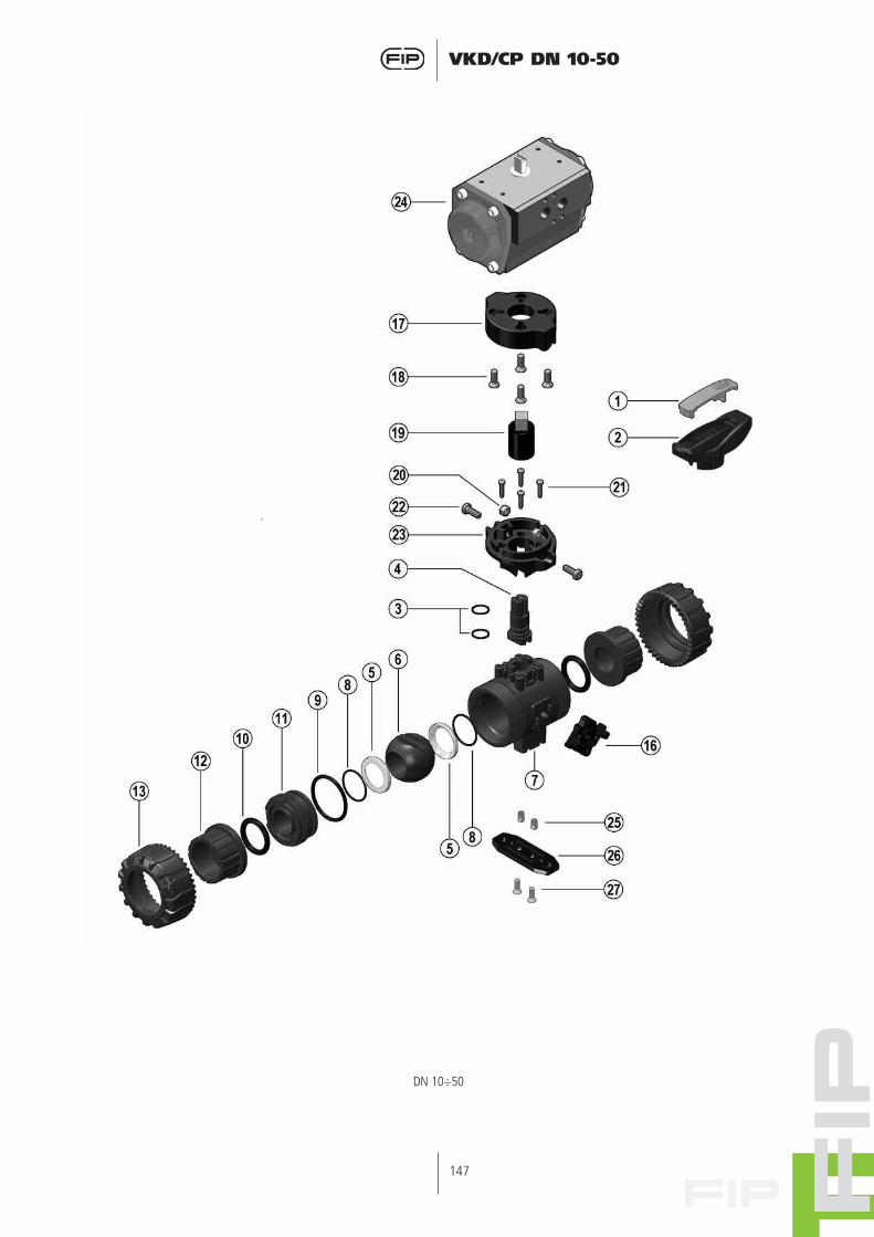
DN 10÷50

148
VKD/CP DN 10-50
Pos.
12345 678
9
10
11
12131617181920212223242526
27
Q.tà
11112112
1
2
1
2211412421121
2
Componenti
Inserto manigliaManiglia
Guarnizione asta comandoAsta comando
Guarnizione sferaSfera
CassaGuarnizione (O-ring) di
supporto della guarnizione 5Guarnizione (O-ring)
di tenuta radialeGuarnizione (O-ring)
di tenuta testaSupporto della guarnizione
della sferaManicotto
GhieraDUAL BLOCK
Piattello superioreVite
Modulo di collegamentoDado
ViteVite
Piattello inferioreAttuatore pneumaticoBoccola di staffaggioPiastrina distanziale
di montaggioVite
Materiale
PVC-UPVC-U
EPDM-FPMPVC-U/PP/PVC-C/PVDF
PTFEPVC-U/PP/PVC-C/PVDFPVC-U/PP/PVC-C/PVDF
EPDM-FPM
EPDM-FPM
EPDM-FPM
PVC-U/PP/PVC-C/PVDF
PVC-U/PP/PVC-C/PVDFPVC-U/PP/PVC-C/PVDF
POMPP-GR
Acciaio inoxPP-GR/Acciaio inox
Acciaio inoxAcciaio inoxAcciaio inox
PP-GRAlluminio trattato
Acciaio inox o ottonePP-GR
Acciaio inox
Pos.
12345678
9
10
11
12131617181920212223242526
27
Materiaux
PVC-UPVC-U
EPDM-FPMPVC-U/PP/PVC-C/PVDF
PTFEPVC-U/PP/PVC-C/PVDFPVC-U/PP/PVC-C/PVDF
EPDM-FPM
EPDM-FPM
EPDM-FPM
PVC-U/PP/PVC-C/PVDF
PVC-U/PP/PVC-C/PVDFPVC-U/PP/PVC-C/PVDF
POMPP-GR
Acier inoxPP-GR/Acier inox
Acier inoxAcier inoxAcier inox
PP-GRAlluminium traité
Acier inox ou LaitonPP-GR
Acier inox
Q.té
11112112
1
2
1
2211412421121
2
Composants
Outil pour démontagePoignée
Joint de la tige de manoeuvreTige de manoeuvre
Garniture de la sphèreSphéreCorps
Joint du supportde la garniture 5
Joint du corps (O-ring)
Joint du collet
Support de la garniture de la sphère
ColletÉcrou union
DUAL BLOCKPlatine supérieure
VisRaccord de passage
ÉcrouVisVis
Platine basseActionneur pneumatique
Ecrous d’ancragePlatine de montage
Vis
Pos.
12345 6789
10111213161718192021222324252627
Components
InsertHandle
Stem O-ringStem
Ball seatBall
BodySupport O-ring for ball seat
Radial seal O-ringSocket seal O-ring
Support for ball seatEnd connector
Union nutDUAL BLOCK
Upper plateScrew
Coupling spindleNut
ScrewScrew
Lower platePneumatic actuator
Bracketing bushMounting/distance plate
Screw
Material
U-PVCU-PVC
EPDM-FPMU-PVC/PP/C-PVC/PVDF
PTFEU-PVC/PP/C-PVC/PVDFU-PVC/PP/C-PVC/PVDF
EPDM-FPMEPDM-FPMEPDM-FPM
U-PVC/PP/C-PVC/PVDFU-PVC/PP/C-PVC/PVDFU-PVC/PP/C-PVC/PVDF
POMPP-GR
Stainless steelPP-GR/Stainless steel
Stainless steelStainless steelStainless steel
PP-GRH.a. alluminium
Stainless steel or brassPP-GR
Stainless steel
Pos.
12345 6789
10111213161718192021222324252627
Benennung
SchlüsseleinsatzHandgriff
O-ringKugelspindelDichtungen
KugelGehäuse
O-Ring (zu Teil 5)O-RingO-Ring
DichtungsträgerAnschlußteile
ÜberwurfmutterDUAL BLOCK
AdapterflanschSchraube
AdaptorspindelMutter
SchraubeSchraube
Untere AnschlussplattePneumatik Antrieb
GewindebuchsenBefestingungsplatte
Schraube
Werkstoff
PVC-UPVC-U
EPDM-FPMPVC-U/PP/PVC-C/PVDF
PTFEPVC-U/PP/PVC-C/PVDFPVC-U/PP/PVC-C/PVDF
EPDM-FPMEPDM-FPMEPDM-FPM
PVC-U/PP/PVC-C/PVDFPVC-U/PP/PVC-C/PVDFPVC-U/PP/PVC-C/PVDF
POMPP-GR
EdelstahlPP-GR/Edelstahl
EdelstahlEdelstahlEdelstahl
PP-GRAlu
Edelstahl oder MessingPP-GR
Edelstahl
Q.ty
1111211212122114124211212
Stûck
1111211212122114124211212

149
VKD/CP DN 10-50