VITA All-Ceramics VITA In-Ceram - Cerec.co.il עמוד ... interesting material for dental...
52
Directions for use Fabrication of the substructure Date of issue: 09-04 VITA In-Ceram ® SPINELL BLANKS for CEREC ® ALUMINA BLANKS for CEREC ® ZIRCONIA BLANKS for CEREC ® 3D - Master Vita System E qu ip m e n t A ll- C e r a m ic s S e r v i c e V e n e e r i n g M a t e r i a l s T ee t h VITA All-Ceramics VITA In-Ceram for CEREC ® / CEREC ® inLab ® ® MACHINABLE CERAMICS VITA
-
Upload
nguyenxuyen -
Category
Documents
-
view
219 -
download
4
Transcript of VITA All-Ceramics VITA In-Ceram - Cerec.co.il עמוד ... interesting material for dental...

Directions for useFabrication of the substructureDate of issue : 09-04
VITA In-Ceram®
SPINELL BLANKS for CEREC®
ALUMINA BLANKS for CEREC®
ZIRCONIA BLANKS for CEREC®
3D - MasterVita System
Equipment All-Ceramics
Serv
ice
VeneeringMaterials
Teeth
VITA All-Ceramics
VITA In-Ceramfor CEREC®/ CEREC® inLab®
®
M A C H I N A B L EC E R A M I C S
V I T A
Table of contents
I. VITA In-Ceram® SPINELL BLANKS for CEREC®
Material-technical aspects of
VITA In-Ceram SPINELL BLANKS for CEREC
VITA In-Ceram SPINELL assortment for CEREC
Fabrication of the substructure
Reworking the substructure
Glass infiltration
Firing charts
II. VITA In-Ceram® ALUMINA BLANKS for CEREC®
Material-technical aspects of
Vita In-Ceram ALUMINA BLANKS for CEREC
VITA In-Ceram manufacturing process (CEREC inLab)
VITA In-Ceram ALUMINA assortment for CEREC
Fabrication of the substructure
Reworking the substructure
Glass infiltration
Firing charts
III. VITA In-Ceram® ZIRCONIA BLANKS for CEREC®
Material-technical aspects of
VITA In-Ceram ZIRCONIA BLANKS for CEREC
VITA In-Ceram ZIRCONIA assortment for CEREC
Fabrication of the substructure
Reworking the substructure
Glass infiltration
Firing charts
page
6
8
9
10
12
16
20
21
22
23
26
28
33
36
38
39
42
44
49
VITA In-Ceram® BLANKS for CEREC® · VITA All-Ceramics page 2
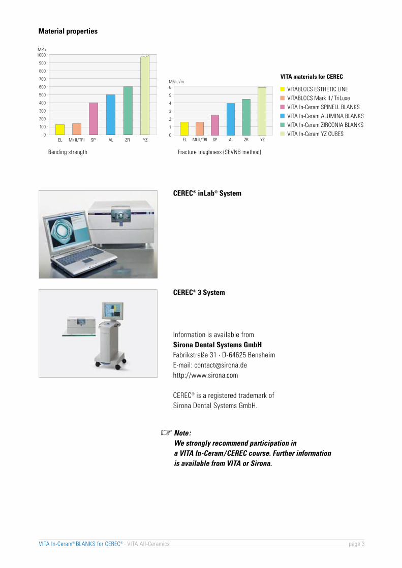
Material properties
CEREC® 3 System
Information is available fromSirona Dental Systems GmbHFabrikstraße 31 · D-64625 BensheimE-mail: [email protected]://www.sirona.com
CEREC® is a registered trademark of Sirona Dental Systems GmbH.
Note:We strongly recommend participation ina VITA In-Ceram /CEREC course. Further informationis available from VITA or Sirona.
VITA In-Ceram® BLANKS for CEREC® · VITA All-Ceramics page 3
EL Mk II/TRI SP AL ZR YZ
6
5
4
3
2
1
0
Bruchzähigkeit / Fracture toughness (KIC)
(SEVNB-Methode / SEVNB-method)MPa ·√m
Biegebruchfestigkeit / Flexural strength
EL Mk II/TRI SP AL ZR YZ
1000
900
800
700
600
500
400
300
200
100
0
MPa
VITABLOCS ESTHETIC LINEVITABLOCS Mark II / TriLuxeVITA In-Ceram SPINELL BLANKSVITA In-Ceram ALUMINA BLANKSVITA In-Ceram ZIRCONIA BLANKSVITA In-Ceram YZ CUBES
Bending strength Fracture toughness (SEVNB method)
VITA materials for CEREC
CEREC® inLab® System
�

*Working time : approx. 19 minutesWaiting time : approx. 2h 30minThe calculation is based on the fabrication of the substructure of a VITA In-Ceram ALUMINAsingle crown without optimizing with glass infiltration in the VITA VACUMAT.
0
min.Working time*
VITA In-Ceram® SPINELL/ALUMINA/ZIRCONIAManufacturing process for CEREC® inLab®
• produce master model
• produce working model
• fix model on the support
• scan model
• design crown coping / bridge structure
• use VITA In-Ceram BLANK for crowns/bridges
• profile grinding (CAM)
• check the fit of the framework
• cleaning firing
• if necessary optimize the margin
• check substructure with testing liquid
• cleaning firing (if margin not optimized)
• apply VITA In-Ceram GLASS POWDER
• glass infiltration firing
• remove excess glass
• 1st glass control firing
• 2nd glass control firing
• veneer with VITA VM 7
VITA In-Ceram® BLANKS for CEREC® · VITA All-Ceramics page 4

VITA All-Ceramics
Directions for useFabrication of the crown substructure
SPINELL BLANKSfor CEREC®/ CEREC® inLab®
VITA In-Ceram
VITA In-Ceram®
ALUMINA
VITA In-Ceram®
SPINELL1)
1)
1)
VITA In-Ceram®
ZIRCONIA
VITA In-Ceram®
YZ-CUBES
Indication
Type of material
–
–
– –
–
–
–
– •
•
°
•
• •
•
°° ° – – –
–
–
•
–
–
–
•
–
•
•
•
•
•
– –
•
–
–
–
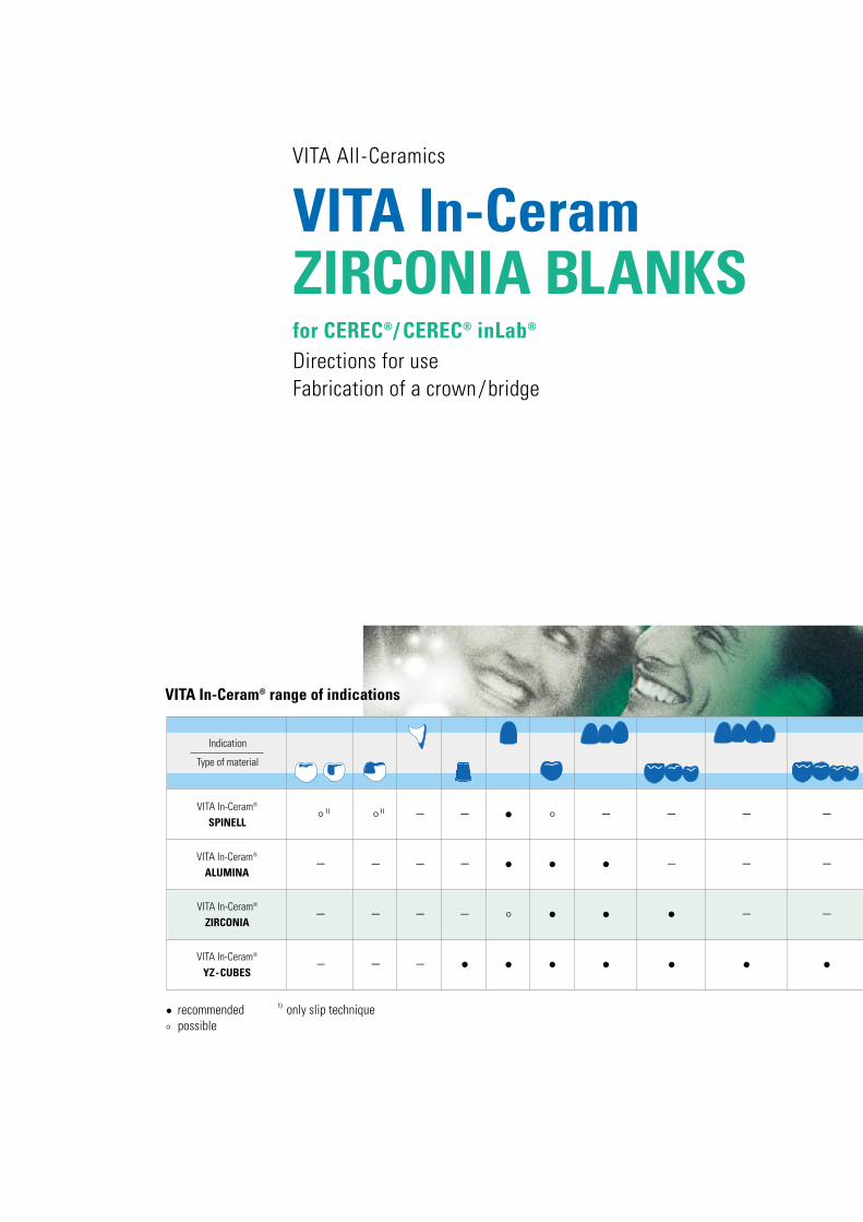
recommended
° possibleonly slip technique•
VITA In-Ceram® range of indications
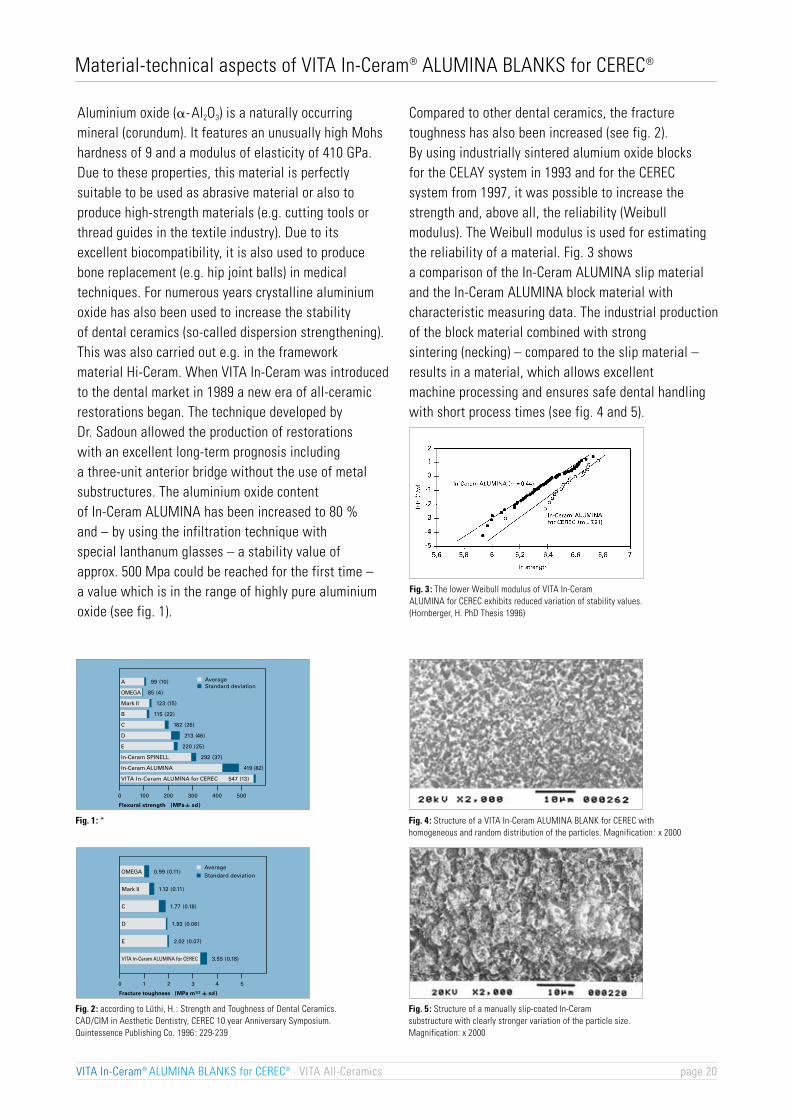
Flexural strength (MPa
AverageA 99 (10)
Mark II 123 (15)
B 115 (22)
C 182 (26)
D 213 (46)
In-Ceram SPINELL 292 (37)
VITA In-Ceram ALUMINA for CEREC 547 (13)
In-Ceram ALUMINA 419 (82)
OMEGA 85 (4)
E 220 (25)
Standard deviation
0 100 200 300 500400
sd)
VITA In-Ceram® SPINELL BLANKS for CEREC® · VITA All-Ceramics page 6
Material-technical aspects of VITA In-Ceram® SPINELL BLANKS for CEREC®
Spinell (MgAl2O4) is a natural mineral that is mainlyfound together with limestone and dolomite, sometimesalso with granite or as sediment in sand. Due to thedifferent types of spinell that are found, the compositionof natural spinell varies strongly.
Therefore, for industrial purposes, spinell isproduced synthetically. Spinell ceramics feature someexcellent material properties: high melting point,high stability and low thermal conductivity allow theuse as refractory material, e.g. in the form of furnacelining. The jewelry industry takes advantage of thegood transparency (see fig. 3).
The combination of high stability, good chemicalresistance and high translucency had turned spinell intoan interesting material for dental technology as well.
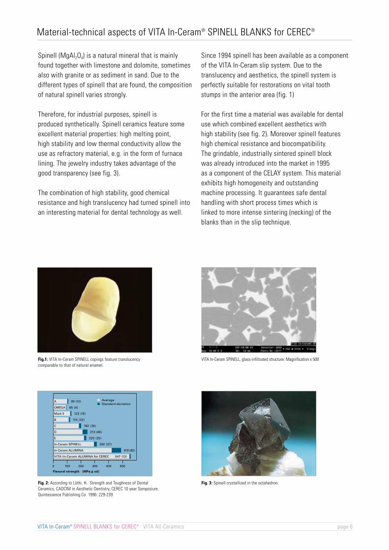
Since 1994 spinell has been available as a componentof the VITA In-Ceram slip system. Due to thetranslucency and aesthetics, the spinell system isperfectly suitable for restorations on vital toothstumps in the anterior area (fig. 1)
For the first time a material was available for dentaluse which combined excellent aesthetics withhigh stability (see fig. 2). Moreover spinell featureshigh chemical resistance and biocompatibility.The grindable, industrially sintered spinell blockwas already introduced into the market in 1995as a component of the CELAY system. This materialexhibits high homogeneity and outstandingmachine processing. It guarantees safe dentalhandling with short process times which islinked to more intense sintering (necking) of theblanks than in the slip technique.
Fig.1: VITA In-Ceram SPINELL copings feature translucencycomparable to that of natural enamel.
Fig. 2: According to Lüthi, H.: Strength and Toughness of DentalCeramics, CADCIM in Aesthetic Dentistry, CEREC 10 year Symposium,Quintessence Publishing Co. 1996: 229-239
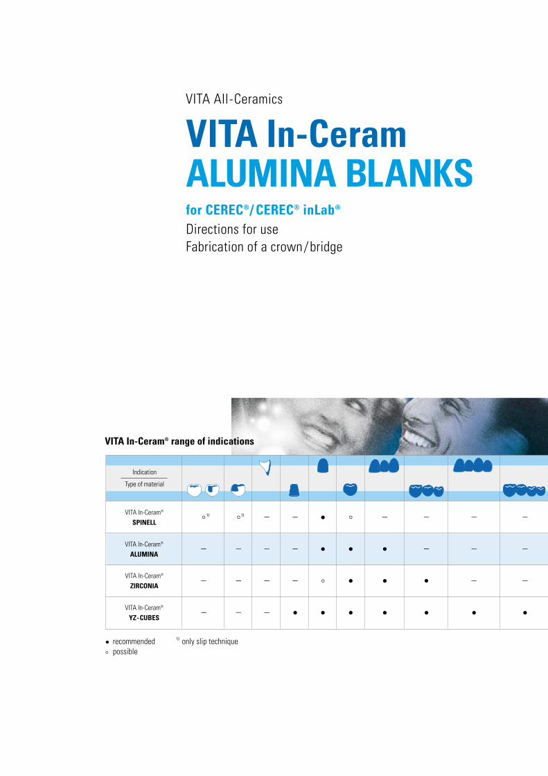
VITA In-Ceram SPINELL, glass-infiltrated structure: Magnification x 500
Fig. 3: Spinell crystallized in the octahedron.

SP
VITA In-Ceram® SPINELL BLANKS for CEREC® · VITA All-Ceramics page 7
Why VITA In-Ceram® SPINELL for CEREC®?
All-ceramic anterior crowns made of VITA In-Ceram SPINELL BLANKS for CEREC have beenclinically approved since 1995 and are based on the reliable systems of VITA In-Ceram and CEREC.They provide the following advantages :
Advantages for the patient :optimum esthetics and excellent biocompatibility, i.e.
- no retraction of gingiva- no exposed metal margin- high quality of fit- excellent translucency, therefore particularly suitable for anterior restorations- withstand high functional stress due to excellent physical values- no thermal irritation due to low thermometric conductivity
positive cost/benefit ratio (e.g. no expenses for alloys)
Advantages for the dentist :VITA In-Ceram SPINELL restorations allow adhesive or non-adhesive fixationX-ray translucency
Advantages for the dental technician: Use of industrially sintered, highly homogeneous VITA In-Ceram SPINELL BLANKS for CEREC The results are:extremely reduced process time compared to the slip technique since there is- no duplicating- no working die- no sinter firing required
- much shorter glass infiltration firing in the conventional ceramic furnace (Inceramat is not required)- layering thickness of the structure can be precisely defined with the CEREC software- minimum processing risk due to safe handling since processing in the fragile condition is no longer required
(no slip-sinter structure, no mixing errors)- completion in the laboratory (no processes performed outside the laboratory)- use of VITA VM 7 fine-structure ceramic as veneering ceramic
When should VITA In-Ceram SPINELL for CEREC® not be used?if a functionally appropriate design of therestoration is not ensuredif sufficient oral hygiene is not presentin case of strongly discolored diesin case of insufficient hard tooth substancein case of inadequate/inappropriate tooth preparationbruxism
For information on preparation and fixation please refer to booklet "Clinical Aspects" – Publication No. 808E.

VITA In-Ceram® SPINELL assortment für CEREC®
Assortment containing a pack of 10 pieces of VITA In-Ceram SPINELLBLANKS for CEREC CS-11 for crowns and accessories to infiltrate groundIn-Ceram SPINELL crown structures.
Content:1 x 25 g VITA In-Ceram SPINELL GLASS POWDER S121 x 6 ml VITA In-Ceram Testing Liquid1 x 10 pcs VITA In-Ceram SPINELL BLANKS for CEREC, CS-111 brush no. 4, In-Ceram1 VITA In-Ceram GLASS POWDER shade guide1 firing tray W for crowns and bridges1 pack of platinum rods for firing tray W, 6 pcs, assorted1 VITA In-Ceram SPINELL OPTIMIZER, 10 gDirections for use VITA In-Ceram BLANKS for CEREC
VITA In-Ceram® SPINELL BLANKS for CEREC®
Porously sintered MgAl2O4 blocks especially foranterior crown substructures,pack cont. 10 pcsDimensions: 10 x 11 x 15 mmDesignation: CS-11 (CROWN SPINELL, size 11)
VITA VM 7 BASIC KIT,Fine-structure ceramic for veneeringVITA In-Ceram SPINELL substructures
VITA VACUMAT®
For glass infiltration of VITA In-Ceram SPINELLsubstructures and for firing the ceramic material VITA VM 7
VITA In-Ceram® SPINELL BLANKS for CEREC® · VITA All-Ceramics page 8

SP
Porously sintered MgAl2O4 blocks especially foranterior crown substructures,pack cont. 10 pcsDimensions: 10 x 11 x 15 mmDesignation: CS-11 (CROWN SPINELL, size 11)
In the VITA In-Ceram SPINELL technique the anterior crownsubstructure must be designed in such a way that it corresponds to the tooth shape to be replaced in reduced size.When veneering with VITA VM 7 this permits a uniform wallthickness of the ceramic on all sides.
Important:Incisal wall thickness: 0.7 mmCircumferential wall thickness: 0.5 mm
Fabrication of the substructure for aVITA In-Ceram® SPINELL for CEREC® anterior crown
The processing steps fromfabrication of the model topreparing for scanning resp. optical impressiondesign of the VITA In-Ceram SPINELLanterior crown coping with the CEREC software
up to
checking on the working modelare carried out analogously to the processing stepsof the substructure fabrication of a VITA In-Ceram ALUMINAfor CEREC restoration.
VITA In-Ceram® SPINELL BLANKS for CEREC® · VITA All-Ceramics page 9
VITA In-Ceram® SPINELL Fabrication of the substructure

Check the material thickness with calipers.Mininum layer thickness: circumferential: 0.5 mm
incisal: 0.7 mm
Important : Contours and function must be checkednow as no further adjustments can beperformed after the glass infiltration firing.
Important note : Since grinding of sintered dentalceramic products produces dust, always wear a face maskor grind when wet. Additionally, use an extraction unitand work behind a protective screen.
If required, small defective spots in the marginal areacan now be filled up with VITA In-Ceram SPINELL OPTIMIZER.
Check the fit of the milled crown substructure on the dieusing varnish, lipstic, etc.
Remove premature contacts, check accuracy of fitat the preparation border.
Adjust the contours using fine-grained diamond abrasivesrotating at low speed and exerting minimum pressure.
If required, remove burrs and excess materialat the margin of the structure using rubber polishers.
Reworking the crown substructure
Remove grinding particles.
Note:Remove the cooling and lubricating fluid DENTATEC fromthe crown coping by means of a cleaning firing. Place substructureon a fibrous pad firing support on firing tray W.
VITA In-Ceram® SPINELL BLANKS for CEREC® · VITA All-Ceramics page 10
Cleaning firing in the VITA VACUMAT®
Predryingtemp. min. °C/min.
Temp.approx. °C min.
VACmin.min.
600 3.00 3.00 33 700 5.00 0.00
�

SP
Use of VITA In-Ceram® SPINELL OPTIMIZERVITA In-Ceram SPINELL OPTIMIZER is a mixture of MgAl2O4 powderand wax and is used to fill up small defects in ground and slip-coatedVITA In-Ceram SPINELL substructures.
I. Optimizing the marginal seal
Apply plaster/wax separating agent onto the die and blowcompletely dry.
If required, carve back the margin as it is done for a metal-free shoulder.
Take up VITA In-Ceram SPINELL OPTIMIZER with an electronic waxknife and apply to the crown margin. The wax temperature mustbe adjusted so that the mixture becomes sufficiently liquid and thewax does not evaporate.
Surplus VITA In-Ceram SPINELL OPTIMIZER must be carved back.
Remove the substructure from the die.
Place the substructure on the model again and check the VITA In-CeramSPINELL OPTIMIZER material that has been applied.
II. SinteringFix the substructure on a platinum rod or place on fibrous pad so that the VITA In-Ceram SPINELL OPTIMIZER will not come into contact with it.
Important note: We strongly recommend the use of ceramic furnaces in which no alloys are fired (risk of contamination).
VITA In-Ceram® SPINELL BLANKS for CEREC® · VITA All-Ceramics page 11
Sinter firing in the VITA VACUMAT®
Predryingtemp. min. °C/min.
Temp.approx. °C min.
VACmin.min.
200 10.00 12.00 78 1140 40.00 0.00

Glass infiltration of the VITA In-Ceram® SPINELL anterior substructures
Checking the substructureThe ground substructure is checked for possible micro-cracksusing the VITA In-Ceram testing liquid.
Should a micro-crack be found, grind the substructure again.
Glass infiltrationMix desired In-Ceram SPINELL glass powder with distilled water to obtain a thin consistency.
Apply a rich coat with a thickness of 1-2 mm only to the outersurfaces of the crown substructure using a brush.
The margin must not be covered.
Note:Apply only small quantities of wet glass powder. Approximate value of the required glass quantity : approx. 60 %of the substructure weight so that only minimum sandblastingis required after the infiltration firing.
Check on the working model.
VITA In-Ceram® SPINELL BLANKS for CEREC® · VITA All-Ceramics page 12
�

SP
Glass infiltration firing in the VITA VACUMAT®
To obtain translucent crown substructures, glass infiltration firingin the VITA VACUMAT must be performed under vacuum.
Place coated crown substructures on platinum rods or platinum foilin the firing support W. The margins must not come in contactwith the rods or foil to prevent the glass from penetrating into theinterior of the restoration.
Important note: We strongly recommend the use of ceramic furnaces in which no alloys are fired (risk of contamination).
VITA In-Ceram® SPINELL BLANKS for CEREC® · VITA All-Ceramics page 13
Glass infiltration firing in the VITA VACUMAT®
CEREC SPINELL crown, at least one glass infiltration firing process
Predryingtemp. min. °C/min.
Temp.approx. °C min.
VACmin.min.
600 4.00 12.00 44 1130 20.00 21.00
VITA SYSTEM 3D-MASTER®/ VITAVM®7S12 for all VITA SYSTEM 3D-MASTER shades incl. OM1, OM2 and OM3for the reproduction of bleached teeth.
VITAPAN® classical/VITADUR® ALPHAS11, S12 for light shadesS13, S14 for yellowish, brownish shades
Determination for VITA In-Ceram® SPINELL GLASS POWDER

Important :In case of incomplete infiltration (white spots)the infiltration process must be repeated.
Remove excess glassRemove excess glass with a coarse-grained diamondinstrument or HEATLESS.
Attention:Glass dust consists of sharp particles. Always wearprotective glasses and a face mask, use anextraction unit and work behind a protective screen.
Important :Do not grind down to the substructure.
Sandblast residual SPINELL glass in the sandblasting unit(disposable abrasive blasting technique) using Al2O3 (30-50 µm)at a max. pressure of 2.5 - 3 bars.
Infiltrated crown coping.
Glass control firing in the VITA VACUMAT®
Place the crown on platinum rods in the VITA firing support Wand carry out glass control firing as follows :
VITA In-Ceram® SPINELL BLANKS for CEREC® · VITA All-Ceramics page 14
Predryingtemp. min. °C/min.
Temp.approx. °C min.
VACmin.min.
600 0.00 5.00 80 1000 5.00 0.00

SP
Important :Unveneered areas of the substructure must besealed with glaze material.
Veneering of the VITA In-Ceram® SPINELLanterior substructures
Crown substructures are veneered with VITA VM 7 accordingto the directions for use 1110E.
Finished VITA In-Ceram SPINELL crown.
Glass that has escaped must be removed by sandblasting again.
Important :For safety's sake this process must be repeated againuntil no more glass is visible. This must always be followedby a glass control firing.
Finished VITA In-Ceram SPINELL anteriorcrown substructure on the model.
VITA In-Ceram SPINELL crown substructuresfeature excellent translucency and are perfectly suitablefor anterior restorations.
VITA In-Ceram® SPINELL BLANKS for CEREC® · VITA All-Ceramics page 15

VITA In-Ceram® SPINELL BLANKS for CEREC® · VITA All-Ceramics page 16
Optimizing with VITA In-Ceram® SPINELL OPTIMIZER (red wax mixture) in the VITA VACUMAT®
Predryingtemp.
VITA VACUMAT
Cleaning firing*
min. °C/min.Temp.
approx. °C min.VACmin.min.
600 3.00 3.00 33 700 5.00 0.00
VITA VACUMATmin. °C/min.
Temp.approx. °C min.
VACmin.min.
600Glass control firing* 0.00 5.00 80 1000 5.00 0.00
Firing charts VITA In-Ceram® SPINELL for CEREC®
200 10.00 12.00 78 1140 40.00 0.00
Predryingtemp.
VITA VACUMATmin. °C/min.
Temp.approx. °C min.
VACmin.min.
600Infiltration 4.00 12.00 44 1130 20.00 21.00
Predryingtemp.
Predryingtemp.
1st dentine firing 500 6.00 7.27 55 910 1.00 7.27
2nd dentine firing 500 6.00 7.16 55 900 1.00 7.16
Sinter firing SPINELL OPTIMIZER
500 0.00 5.00 80 900 1.00 0.00Glaze firing with
VITA Akzent FLUID
500 6.00 7.38 55 920 1.00 7.38VITAVM7 EFFECT
LINER firing
500 4.00 5.00 80 900 1.00 0.00Glaze firing with
VITA Akzent glaze
500 6.00 7.27 55 900 1.00 0.00Glaze firing with VITASHADING PASTE glaze
500 4.00 6.00 55 830 1.00 6.00Corrective firing with
VITAVM 7 CORRECTIVE
Glass infiltration VITA In-Ceram® SPINELL for CEREC® crown in the VITA VACUMAT®
Veneering of VITA In-Ceram® SPINELL for CEREC® anterior crown with VITAVM®7 in the VITA VACUMAT®
Glass infiltration firing VITA In-Ceram® SPINELL for CEREC® anterior crown in the im VITA VACUMAT®
min. min. °C/min.Temp.
approx. °C min.VACmin.
VITA VACUMAT
Cleaning firing is generallycarried out prior to optimizing andglass infiltration.
*
Repeat after sandblasting*
Glaze firing 500 0.00 5.00 80 900 1.00 0.00

VITA In-Ceram® SPINELL BLANKS for CEREC® · VITA All-Ceramics page 17
For personal notes

VITA In-Ceram® SPINELL BLANKS for CEREC® · VITA All-Ceramics page 18
For personal notes
VITA All-Ceramics
Directions for useFabrication of a crown/bridge
ALUMINA BLANKSfor CEREC®/ CEREC® inLab®
VITA In-Ceram
VITA In-Ceram®
ALUMINA
VITA In-Ceram®
SPINELL1)
1)
1)
VITA In-Ceram®
ZIRCONIA
VITA In-Ceram®
YZ-CUBES
Indication
Type of material
–
–
– –
–
–
–
– •
•
°
•
• •
•
°° ° – – –
–
–
•
–
–
–
•
–
•
•
•
•
•
– –
•
–
–
–
recommended
° possibleonly slip technique•
VITA In-Ceram® range of indications
Flexural strength (MPa
AverageA 99 (10)
Mark II 123 (15)
B 115 (22)
C 182 (26)
D 213 (46)
In-Ceram SPINELL 292 (37)
VITA In-Ceram ALUMINA for CEREC 547 (13)
In-Ceram ALUMINA 419 (82)
OMEGA 85 (4)
E 220 (25)
Standard deviation
0 100 200 300 500400
sd)
Fracture toughness (MPa m1/2 sd)
Mark II 1.12 (0.11)
C 1.77 (0.18)
D 1.93 (0.06)
E 2.02 (0.07)
VITA In-Ceram ALUMINA for CEREC 3.55 (0.18)
0 1 2 3 54
OMEGA 0.99 (0.11)AverageStandard deviation
VITA In-Ceram® ALUMINA BLANKS for CEREC® · VITA All-Ceramics page 20
Material-technical aspects of VITA In-Ceram® ALUMINA BLANKS for CEREC®
Aluminium oxide (�-Al2O3) is a naturally occurringmineral (corundum). It features an unusually high Mohshardness of 9 and a modulus of elasticity of 410 GPa.Due to these properties, this material is perfectlysuitable to be used as abrasive material or also toproduce high-strength materials (e.g. cutting tools orthread guides in the textile industry). Due to itsexcellent biocompatibility, it is also used to producebone replacement (e.g. hip joint balls) in medical techniques. For numerous years crystalline aluminiumoxide has also been used to increase the stabilityof dental ceramics (so-called dispersion strengthening).This was also carried out e.g. in the frameworkmaterial Hi-Ceram. When VITA In-Ceram was introducedto the dental market in 1989 a new era of all-ceramic restorations began. The technique developed byDr. Sadoun allowed the production of restorationswith an excellent long-term prognosis includinga three-unit anterior bridge without the use of metalsubstructures. The aluminium oxide contentof In-Ceram ALUMINA has been increased to 80 %and – by using the infiltration technique withspecial lanthanum glasses – a stability value ofapprox. 500 Mpa could be reached for the first time –a value which is in the range of highly pure aluminiumoxide (see fig. 1).
Compared to other dental ceramics, the fracturetoughness has also been increased (see fig. 2). By using industrially sintered alumium oxide blocksfor the CELAY system in 1993 and for the CERECsystem from 1997, it was possible to increase thestrength and, above all, the reliability (Weibullmodulus). The Weibull modulus is used for estimatingthe reliability of a material. Fig. 3 showsa comparison of the In-Ceram ALUMINA slip materialand the In-Ceram ALUMINA block material withcharacteristic measuring data. The industrial productionof the block material combined with strongsintering (necking) – compared to the slip material –results in a material, which allows excellentmachine processing and ensures safe dental handlingwith short process times (see fig. 4 and 5).
Fig. 2 : according to Lüthi, H. : Strength and Toughness of Dental Ceramics.CAD/CIM in Aesthetic Dentistry, CEREC 10 year Anniversary Symposium.Quintessence Publishing Co. 1996: 229-239
Fig. 5 : Structure of a manually slip-coated In-Ceramsubstructure with clearly stronger variation of the particle size.Magnification: x 2000
Fig. 1: * Fig. 4 : Structure of a VITA In-Ceram ALUMINA BLANK for CEREC withhomogeneous and random distribution of the particles. Magnification : x 2000
Fig. 3 : The lower Weibull modulus of VITA In-CeramALUMINA for CEREC exhibits reduced variation of stability values.(Hornberger, H. PhD Thesis 1996)

AL
Why VITA In-Ceram® ALUMINA for CEREC®?
All-ceramic restorations made of VITA In-Ceram ALUMINA BLANKS for CEREC have provedtheir clinical reliability since 1993 and are based on the dependable systems VITA In-Ceram and CEREC.They provide the following advantages:
Advantages for the patient :optimum aesthetics and excellent biocompatibility, i.e.
- no retraction of gingiva- no exposed metal margin- high quality of fit- favourable translucency- withstand high functional stress due to excellent physical values- no thermal irritation due to low thermometric conductivity
positive cost/benefit ratio (no expenses for alloys)
Advantages for the dentist :Clinical reliabilityVITA In-Ceram ALUMINA restorations allow adhesive or non-adhesive fixationX-ray translucency
Advantages for the dental technician:Use of industrially sintered, highly homogeneous VITA In-Ceram ALUMINA BLANKS for CEREC The result is :extremely reduced process time compared to the slip technique since there is- no duplicating- no working die- no sinter firing required
- extremely reduced glass infiltration firing in the conventional ceramic furnace (VITA INCERAMAT is not required)- layering thickness of the structure can be precisely defined with the CEREC software- minimum processing risk due to safe handling since processing in the fragile condition is no longer required
(no slip-sinter structure, no mixing errors)- completion in the laboratory (no processes performed outside the laboratory)- use of VITAVM 7 fine-structure ceramic as veneering ceramic
When should VITA In-Ceram ALUMINA for CEREC® not be used?if a functionally appropriate design of therestoration is not ensuredif sufficient oral hygiene is not presentin case of insufficient hard tooth substancein case of inadequate/inappropriate tooth preparationbruxism
For information on preparation and fixation please refer to booklet "Clinical Aspects" – Publication No. 808E.
VITA In-Ceram® ALUMINA BLANKS for CEREC® · VITA All-Ceramics page 21

VITA In-Ceram® ALUMINA assortment for CEREC®
Assortment containing a pack of 10 pieces of VITA In-Ceram ALUMINABLANKS for CEREC CA-12 for crowns and accessories to infiltrate milledIn-Ceram ALUMINA crown structures.
Content :2 x 25 g VITA In-Ceram ALUMINA GLASS POWDER AL2, AL41 x 6 ml VITA In-Ceram Testing Liquid1 x 10 pcs VITA In-Ceram ALUMINA BLANKS for CEREC, CA-121 brush no. 4, In-Ceram1 VITA In-Ceram GLASS POWDER shade guide1 firing tray W for crowns and bridges1 pack of platinum rods for firing tray W, 6 pcs, assorted1 VITA In-Ceram ALUMINA OPTIMIZER, 10 gDirections for use VITA In-Ceram BLANKS for CEREC
VITA In-Ceram® ALUMINA BLANKS for CEREC®
Porously sintered Al2O3 blocks for crown substructures,pack cont. 10 pcsDimensions: 10 x 12 x 15 mmDesignation: CA-12 (CROWN ALUMINA, size 12)
Porously sintered Al2O3 blocks forthree-unit anterior bridge substructures,pack cont. 2 pcsDimensions: 14 x 15 x 28 mmDesignation: BA-28 (BRIDGE ALUMINA, size 28)
VITA VACUMAT®
For glass infiltration of VITA In-Ceram ALUMINAsubstructures and for firing the ceramic material VITA VM 7
VITA In-Ceram® ALUMINA BLANKS for CEREC® · VITA All-Ceramics page 22
VITA VM 7 BASIC KIT,Fine-structure ceramic for veneeringVITA In-Ceram ALUMINA substructures

AL
Model fabricationDegrease the model.
Check the sawed die carefully.Block out defects and undercuts in the die.Mark the preparation margin with a color superpolymer lead.
Produce a model with removable dies froma high-quality, dimensionally stable plaster, e.g.CAM-base (Dentona Co.).Produce gingival mask.
Preparing for scanning or optical impressionApply covering layer of VITA CEREC LIQUID on the die.Blow the excess thin.Spray VITA CEREC POWDER in a thin, homogenouslayer onto the die.
Fabrication of the substructure for aVITA In-Ceram® ALUMINA/CEREC® crown and anterior bridge
The thin, opaque powder layer of powder results in a homogeneousdispersion of light, dazzle effects are prevented and a uniformsurface is defined. This is the prerequisite for a sharply contrastingimage resp. for perfect digitalization of the die surface.
Note:When using CAM-base as model material the applicationof VITA CEREC LIQUID and POWDER is not required.
VITA In-Ceram® ALUMINA BLANKS for CEREC® · VITA All-Ceramics page 23
�
A.K.
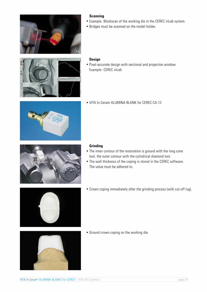
ScanningExample: Blockscan of the working die in the CEREC inLab system.Bridges must be scanned on the model holder.
DesignPixel-accurate design with sectional and projection windowExample: CEREC inLab
GrindingThe inner contour of the restoration is ground with the long conetool, the outer contour with the cylindrical diamond tool.The wall thickness of the coping is stored in the CEREC software.The value must be adhered to.
VITA In-Ceram ALUMINA BLANK for CEREC CA-12
Crown coping immediately after the grinding process (with cut-off lug).
Ground crown coping on the working die.
VITA In-Ceram® ALUMINA BLANKS for CEREC® · VITA All-Ceramics page 24

AL
Design of the substructure of a VITA In-Ceram®
ALUMINA for CEREC® crown/anterior bridge
When using the VITA In-Ceram ALUMINA technique, the crownsubstructures must always be designed in such a way thatthey correspond to the tooth being replaced in a reduced size.Accordingly, homogeneous wall thickness on all sides canbe achieved when veneering with VITA VM 7.
Important :Occlusal resp. incisal wall thickness: 0.7 mmCircumferential wall thickness: 0.5 mm
3-unit anterior bridge substructures in the VITA In-CeramALUMINA technique must always be designed in a way that theycorrespond to the teeth being replaced in a reduced size.Accordingly, homogeneous wall thickness on all sides can beachieved when veneering with VITA VM 7.
The junctures (connectors) should be designed as large aspossible – making maximum use of the space available.
The connector areas must be at least 9 mm2.
The junctures must be rounded off concavely. Deep grooves(e.g. with a diamond separating disc) must be avoided since theywould inevitably lead to cracks.
Important :Aspects for the design of connectors of bridge substructures:1. The height of the connector should be as large as possible. 2. The height should be equal to or larger than width b.
Stability and function take priority over aesthetics!
VITA In-Ceram® ALUMINA BLANKS for CEREC® · VITA All-Ceramics page 25
Bru
chla
st F
1:2 3:4 1:1 5:4 3:2
Verhältnis Höhe : Breite des Verbinders
F
F
Breite b
Höhe h
F
at least. 9mm2
Ratio of height: width of the connector
Bre
akin
g lo
ad F
Height h
Width b
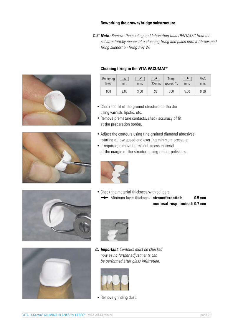
Adjust the contours using fine-grained diamond abrasivesrotating at low speed and exerting minimum pressure.If required, remove burrs and excess materialat the margin of the structure using rubber polishers.
Check the material thickness with calipers.Mininum layer thickness: circumferential: 0.5 mm
occlusal resp. incisal: 0.7 mm
Important: Contours must be checkednow as no further adjustments canbe performed after glass infiltration.
Remove grinding dust.
Check the fit of the ground structure on the dieusing varnish, lipstic, etc.Remove premature contacts, check accuracy of fitat the preparation border.
Note: Remove the cooling and lubricating fluid DENTATEC from thesubstructure by means of a cleaning firing and place onto a fibrous padfiring support on firing tray W.
Cleaning firing in the VITA VACUMAT®
VITA In-Ceram® ALUMINA BLANKS for CEREC® · VITA All-Ceramics page 26
Predryingtemp. min. °C/min.
Temp.approx. °C min.
VACmin.min.
600 3.00 3.00 33 700 5.00 0.00
�
Reworking the crown/bridge substructure

AL
I. Optimizing the marginal sealApply plaster/wax separating agent onto the die and blow completely dry.If required, carve back the margin as it is done for a metal-free shoulder.Take up VITA In-Ceram ALUMINA OPTIMIZER with an electronic waxknife and apply to the crown/bridge margin. The wax temperaturemust be adjusted so that the mixture becomes sufficiently liquid andthe wax does not evaporate.Surplus VITA In-Ceram ALUMINA OPTIMIZER must be carved back.Remove the substructure from the die.Place the substructure on the model again and check VITA In-CeramALUMINA OPTIMIZER material that has been applied.
II. SinteringFix the substructure on a platinum rod or place on a fibrous padfiring support so that the VITA In-Ceram ALUMINA OPTIMIZER willnot come into contact with it.
The use of VITA In-Ceram® ALUMINA OPTIMIZERVITA In-Ceram ALUMINA OPTIMIZER is a mixture of Al2O3 powderand wax and is used to fill up small defects in ground, slip-coated andsintered VITA In-Ceram ALUMINA substructures.
Important note:We strongly recommend the use of ceramic furnaces in which no alloys are fired (risk of contamination).
Check on the working model.
Sinter firing in the VITA VACUMAT®
Important note:Since grinding of sintered dental ceramic products produces dust, always wear a face mask or grind when wet.Additionally, use an extraction unit and work behinda protective screen.
If required, small defective spots in the marginal area can nowbe filled up with VITA In-Ceram ALUMINA OPTIMIZER.
VITA In-Ceram® ALUMINA BLANKS for CEREC® · VITA All-Ceramics page 27
Predryingtemp. min. °C/min.
Temp.approx. °C min.
VACmin.min.
200 10.00 12.00 77 1120 40.00 0.00

VITAPAN® classical / VITADUR® ALPHA
Determination table for VITA In-Ceram® ALUMINA GLASS POWDER
VITA SYSTEM 3D-MASTER® / VITAVM®7
Glass infiltration of the VITA In-Ceram® ALUMINA substructures
Check of the substructureThe ground substructure is checked for possible micro-cracksusing the VITA In-Ceram testing liquid.
Should a micro-crack be detected, the frameworkmust be ground again.
Note:Apply only small quantities of wet glass powder. The required glass quantity is approx. 75 %of the substructure weight so that only minimumsandblasting is required.
Important :During glass infiltration of bridge substructures on platinum foilthe basal surface of the pontic – in all infiltration firings – must not becovered with glass powder so that the air can escape from the substructure. Correct glass infiltration is possible only if this is ensured.
Glass infiltrationMix desired In-Ceram ALUMINA glass powder withdistilled water to obtain a thin consistency. Apply 1-2 rich coats with a thickness of 1-2 mm only to the outersurfaces of the crown or bridge substructure using a brush.At the beginning, apply only half of the glass powder quantityto the bridge substructure.The margin must not be covered.
VITA In-Ceram® ALUMINA BLANKS for CEREC® · VITA All-Ceramics page 28
OM1*
AL2
OM2*
AL2
OM3*
AL2
1M1
AL2
1M2
AL2
2L1.5
AL2
2L2.5
AL2
2M1
AL2
2M2
AL2
2M3
AL2
2R1.5
AL2
2R2.5
AL2
3L1.5
AL2
3L2.5
AL2
3M1
AL2
3M2
AL2
3M3
AL2
3R1.5
AL2
3R2.5
AL2
4L1.5
AL4
4L2.5
AL4
4M1
AL4
4M2
AL4
4M3
AL4
4R1.5
AL4
4R2.5
AL4
5M1
AL4
5M2
AL4
5M3
AL4
A1
AL1
A2
AL2
A3
AL2
A3.5
AL3
A4
AL3
B1
AL1
B2
AL2
B3
AL2
B4
AL3
C1
AL3
C2
AL3
C3
AL4
C4
AL4
D2
AL1
D3
AL2
D4
AL3
�
* Shades for the reproduction of bleached teeth

Glass infiltration firing in the VITA INCERAMAT
VITA In-Ceram ALUMINA for CEREC crown
VITA In-Ceram ALUMINA for CEREC anterior bridge
Glass infiltration firing in the VITA VACUMAT®
Alternatively, glass infiltration can also be carriedout in the VITA VACUMAT.
AL
Important note:We strongly recommend the use of ceramic furnaces in whichno alloys are fired (risk of contamination).
Glass infiltration firing in the VITA INCERAMATPlace the coated crown or bridge substructure on a piece of platinumfoil on firing tray W 0.1 mm thick (Pt/Au 95/5 Heraeus Kulzer –available in two sizes: 60 x 100 x 0.1 mm or 60 x 50 x 0.1 mm) in orderto carry out the glass infiltration firing. The margins must not comeinto contact with the platinum foil to prevent the glass from penetratinginto the inside of the substructure.
Place coated substructures on platinum rods or platinum foilin the firing support W. The margins must not come incontact with the rods or the foil to prevent the glass frompenetrating into the inside of the restoration.
VITA In-Ceram® ALUMINA BLANKS for CEREC® · VITA All-Ceramics page 29
Time 1
h:min
0:00 0:00 0:30 1:00 200 1140
Time 4
h:min
Time 3
h:min
Time 2
h:min
Temp. 2
approx. °C
Temp. 1
approx. °C
Time 1
h:min
0:00 0:00 0:30 1:00 200 1140
Time 4
h:min
Time 3
h:min
Time 2
h:min
Temp. 2
approx. °C
Temp. 1
approx. °C
Cooling down to 400 °C in the closed furnace.

Important :In the case of incomplete infiltration (white areas in the left coping)the infiltration process must be repeated.
Glass infiltration in the VITA VACUMAT®
VITA In-Ceram ALUMINA for CEREC crown, at leastone glass infiltration firing process
VITA In-Ceram ALUMINA for CEREC anterior bridge,at least two glass infiltration firing processes on platinum foil.At 1st firing only apply half of the glass quantity.
1st infiltration firing (50% of glass quantity)
2nd infiltration firing (50% of glass quantity)
Note:When firing bridges the object must be placed on platinum foil,which is placed onto firing tray W.
VITA In-Ceram® ALUMINA BLANKS for CEREC® · VITA All-Ceramics page 30
Predryingtemp. min. °C/min.
Temp.approx. °C min.
VACmin.min.
600 1.00 7.00 77 1140 30.00 33.00
Predryingtemp. min. °C/min.
Temp.approx. °C min.
VACmin.min.
600 1.00 7.00 77 1140 40.00 40.00
Predryingtemp. min. °C/min.
Temp.approx. °C min.
VACmin.min.
600 1.00 7.00 77 1140 40.00 40.00
�

AL
Remove excess glass
Remove excess glass with a coarse-grained diamondinstrument or HEATLESS.
Attention: Glass dust consists of sharp particles. Always wearprotective glasses and a face mask, use an extractionunit and work behind a protective screen.
Important :Do not grind down to the substructure.
Sandblast residual ALUMINA glass in the sandblasting unit(disposable abrasive blasting technique) using Al2O3 (30-50 µm)at a pressure of 6 bars (cervical : 3 bars).
Infiltrated substructure on platinum foil.
VITA In-Ceram® ALUMINA BLANKS for CEREC® · VITA All-Ceramics page 31

Veneering of the VITA In-Ceram® ALUMINA substructuresCrown/bridge substructures are veneered with VITA VM 7 accordingto the directions for use 1110 E.
Glass control firing in the VITA VACUMAT®
Glass control firing on platinum rods in the firing support W as follows :
Glass that has escaped must be removed by sandblasting again.
Important : For safety’s sake this procedure must be repeated untilno more glass is visible. After this, a glass infiltration firingmust always be carried out.
Finished VITA CEREC ALUMINA substructures on the working model.
Important : Unveneered areas of the substructure mustbe sealed with glaze material.
Finished 3-unit In-Ceram ALUMINA anterior bridge.
VITA In-Ceram® ALUMINA BLANKS for CEREC® · VITA All-Ceramics page 32
Predryingtemp. min. °C/min.
Temp.approx. °C min.
VACmin.min.
600 0.00 5.00 80 1000 5.00 0.00
AL
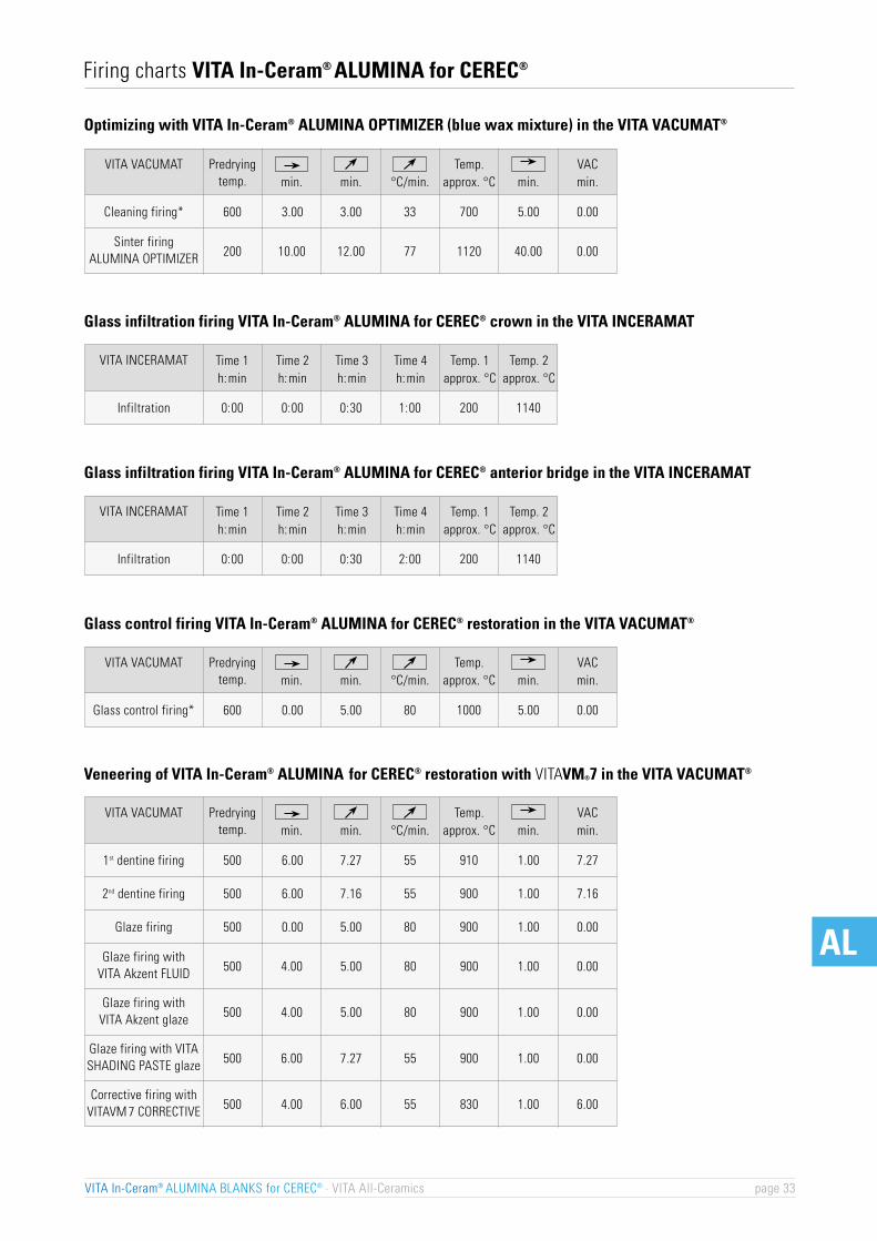
Optimizing with VITA In-Ceram® ALUMINA OPTIMIZER (blue wax mixture) in the VITA VACUMAT®
VITA In-Ceram® ALUMINA BLANKS for CEREC® · VITA All-Ceramics page 33
Predryingtemp.
VITA VACUMAT
Cleaning firing*
min. °C/min.Temp.
approx. °C min.VACmin.min.
600 3.00 3.00 33 700 5.00 0.00
VITA INCERAMAT
0:00 0:30 1:00 200 1140
VITA VACUMATmin. °C/min.
Temp.approx. °C min.
VACmin.min.
600Glass control firing* 0.00 5.00 80 1000 5.00 0.00
Firing charts VITA In-Ceram® ALUMINA for CEREC®
200 10.00 12.00 77 1120 40.00 0.00
Time 1h:min
Time 4h:min
Time 3h:min
Time 2h:min
Temp. 2approx. °C
Temp. 1approx. °C
Infiltration 0:00
VITA INCERAMAT
0:00 0:30 2:00 200 1140
Time 1h:min
Time 4h:min
Time 3h:min
Time 2h:min
Temp. 2approx. °C
Temp. 1approx. °C
Infiltration 0:00
Predryingtemp.
VITA VACUMATmin. °C/min.
Temp.approx. °C min.
VACmin.min.
Predryingtemp.
1st dentine firing 500 6.00 7.27 55 910 1.00 7.27
2nd dentine firing 500 6.00 7.16 55 900 1.00 7.16
Glaze firing 500 0.00 5.00 80 900 1.00 0.00
Sinter firing ALUMINA OPTIMIZER
500 4.00 5.00 80 900 1.00 0.00Glaze firing with
VITA Akzent FLUID
500 4.00 5.00 80 900 1.00 0.00Glaze firing with
VITA Akzent glaze
500 6.00 7.27 55 900 1.00 0.00Glaze firing with VITASHADING PASTE glaze
500 4.00 6.00 55 830 1.00 6.00Corrective firing with
VITAVM 7 CORRECTIVE
Glass infiltration firing VITA In-Ceram® ALUMINA for CEREC® crown in the VITA INCERAMAT
Glass control firing VITA In-Ceram® ALUMINA for CEREC® restoration in the VITA VACUMAT®
Veneering of VITA In-Ceram® ALUMINA for CEREC® restoration with VITAVM®7 in the VITA VACUMAT®
Glass infiltration firing VITA In-Ceram® ALUMINA for CEREC® anterior bridge in the VITA INCERAMAT

For personal notes
VITA In-Ceram® ALUMINA BLANKS for CEREC® · VITA All-Ceramics page 34
VITA All-Ceramics
Directions for useFabrication of a crown/bridge
ZIRCONIA BLANKSfor CEREC®/ CEREC® inLab®
VITA In-Ceram
VITA In-Ceram®
ALUMINA
VITA In-Ceram®
SPINELL1)
1)
1)
VITA In-Ceram®
ZIRCONIA
VITA In-Ceram®
YZ-CUBES
Indication
Type of material
–
–
– –
–
–
–
– •
•
°
•
• •
•
°° ° – – –
–
–
•
–
–
–
•
–
•
•
•
•
•
– –
•
–
–
–
recommended
° possibleonly slip technique•
VITA In-Ceram® range of indications
VITA In-Ceram® ZIRCONIA BLANKS for CEREC® · VITA All-Ceramics page 36
Material-technical aspects of VITA In-Ceram® ZIRCONIA BLANKS for CEREC®
Zirconium oxide (ZrO2) is a mineral that is found in naturein the form of baddeleyite (zirconium earth). It featuresa Mohs' hardness of 7-9 and – similar to aluminiumoxide – is suitable for producing abrasive discs. It hasalso proved its reliability for domestic and industrialcutting instruments. Due to its high strength and fracturetoughness it is also suitable for the production of hipprostheses. It has also been used as opacifier for metalceramic opaque materials. For this purpose, however,synthetically produced ZrO2 is used, since the naturalmaterial exhibits excessive contamination.
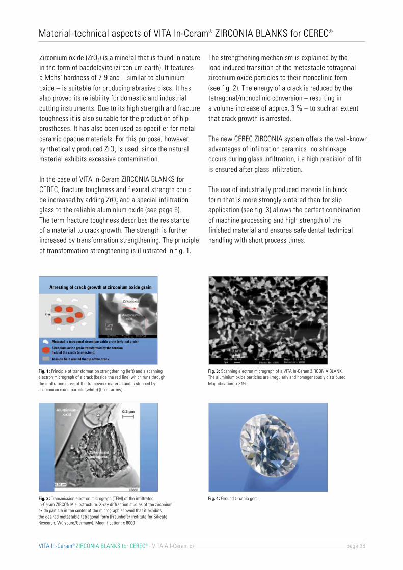
In the case of VITA In-Ceram ZIRCONIA BLANKS forCEREC, fracture toughness and flexural strength couldbe increased by adding ZrO2 and a special infiltrationglass to the reliable aluminium oxide (see page 5).The term fracture toughness describes the resistanceof a material to crack growth. The strength is furtherincreased by transformation strengthening. The principleof transformation strengthening is illustrated in fig. 1.
The strengthening mechanism is explained by theload-induced transition of the metastable tetragonalzirconium oxide particles to their monoclinic form(see fig. 2). The energy of a crack is reduced by thetetragonal/monoclinic conversion – resulting ina volume increase of approx. 3 % – to such an extentthat crack growth is arrested.
The new CEREC ZIRCONIA system offers the well-knownadvantages of infiltration ceramics: no shrinkageoccurs during glass infiltration, i.e high precision of fitis ensured after glass infiltration.
The use of industrially produced material in blockform that is more strongly sintered than for slipapplication (see fig. 3) allows the perfect combinationof machine processing and high strength of thefinished material and ensures safe dental technicalhandling with short process times.
Fig. 1 : Principle of transformation strengthening (left) and a scanningelectron micrograph of a crack (beside the red line) which runs throughthe infiltration glass of the framework material and is stopped bya zirconium oxide particle (white) (tip of arrow).
Fig. 2 : Transmission electron micrograph (TEM) of the infiltratedIn-Ceram ZIRCONIA substructure. X-ray diffraction studies of the zirconiumoxide particle in the center of the micrograph showed that it exhibitsthe desired metastable tetragonal form (Fraunhofer Institute for SilicateResearch, Würzburg/Germany). Magnification: x 8000
Fig. 3 : Scanning electron micrograph of a VITA In-Ceram ZIRCONIA BLANK.The aluminium oxide particles are irregularly and homogeneously distributed.Magnification: x 3190
Fig. 4 : Ground zirconia gem.
Metastable tetragonal zirconium oxide grain (original grain)
Zirconium oxide grain transformed by the tensionfield of the crack (monoclinic)
Tension field around the tip of the crack
Riss
Arresting of crack growth at zirconium oxide grain

ZR
Why VITA In-Ceram® ZIRCONIA for CEREC®?
All-ceramic restorations made of VITA In-Ceram ZIRCONIA BLANKS for CERECare based on the reliable systems of VITA In-Ceram Infiltration Ceramics and CERECand provide the following advantages.
Advantages for the patient :optimum aesthetics and excellent biocompatibility, i.e.
- no retraction of gingiva- no exposed metal margin- high quality of fit- favourable translucency- withstand high functional stress due to excellent physical values- no thermal irritation due to low thermometric conductivity
positive cost/benefit ratio (no expenses for alloys)
Advantages for the dentist :Clinical reliabilityVITA In-Ceram ZIRCONIA restorations allow adhesive or non-adhesive fixation
Advantages for the dental technician:Use of industrially sintered, highly homogeneous VITA In-Ceram ZIRCONIA BLANKS for CEREC The result is :extremely reduced process time compared to the slip technique since there is- no duplicating- no working die- no sinter firing required
- much shorter glass infiltration firing in the conventional ceramic furnace (Inceramat is not required)- layering thickness of the structure can be precisely defined with the CEREC software- minimum processing risk due to safe handling since processing in the fragile condition is no longer
required (no slip-sinter structure, no mixing errors)- completion in the laboratory (no processes performed outside the laboratory)- use of VITA VM 7 fine-structure ceramic as veneering ceramic
When should VITA In-Ceram® ZIRCONIA for CEREC® not be used?If a functionally appropriate design of therestoration is not ensured. If sufficient oral hygiene is not given.in case of insufficient hard tooth substancein case of inadequate/inappropriate tooth preparationbruxism
For information on preparation and fixation please refer to booklet ”Clinical Aspects”, Publication No. 808E
VITA In-Ceram® ZIRCONIA BLANKS for CEREC® · VITA All-Ceramics page 37

VITA VACUMAT®
For glass infiltrationof VITA In-CeramZIRCONIA substructuresand for firing the ceramicmaterial VITA VM 7
VITA In-Ceram® ZIRCONIA assortment for CEREC®
Assortment containing a pack of 10 pieces of VITA In-CeramZIRCONIA BLANKS for CEREC CZ-12 for crowns and accessoriesto infiltrate ground In-Ceram ZIRCONIA crown structures.
Content :1 x 25 g VITA In-Ceram ZIRCONIA GLASS POWDER Z 22N1 x 10 pcs VITA In-Ceram ZIRCONIA BLANKS for CEREC, CZ-121 VITA In-Ceram ZIRCONIA OPTIMIZER, 8 gDirections for use – VITA In-Ceram BLANKS for CEREC
VITA In-Ceram® ZIRCONIA BLANKS for CEREC® · VITA All-Ceramics page 38
VITA In-Ceram® ZIRCONIA BLANKS for CEREC®
Porously sintered Al2O3/ZrO2 blocks for crown substructures,pack cont. 10 pcsDimensions: 10 x 12 x 15 mmDesignation: CZ-12 (CROWN ZIRCONIA, size 12)
Porously sintered Al2O3/ZrO2 blocks for crown substructures,pack cont. 5 pcsDimensions: 14 x 15 x 18 mmDesignation: CZ-18 (CROWN ZIRCONIA, size 18)
Porously sintered Al2O3/ZrO2 blocks forthree-unit posterior bridge substructures,pack cont. 2 pcsDimensions: 14 x 15 x 33 mmDesignation: BZ-33 (BRIDGE ZIRCONIA, size 33)
Porously sintered Al2O3/ZrO2 blocks forthree-unit posterior bridge substructures,pack cont. 2 pcsDimensions: 14 x 15 x 40 mmDesignation: BZ-40(BRIDGE ZIRCONIA, size 40)
VITA VM 7 fine-structure ceramicfor veneering VITA In-Ceram ZIRCONIAsubstructures
ZR
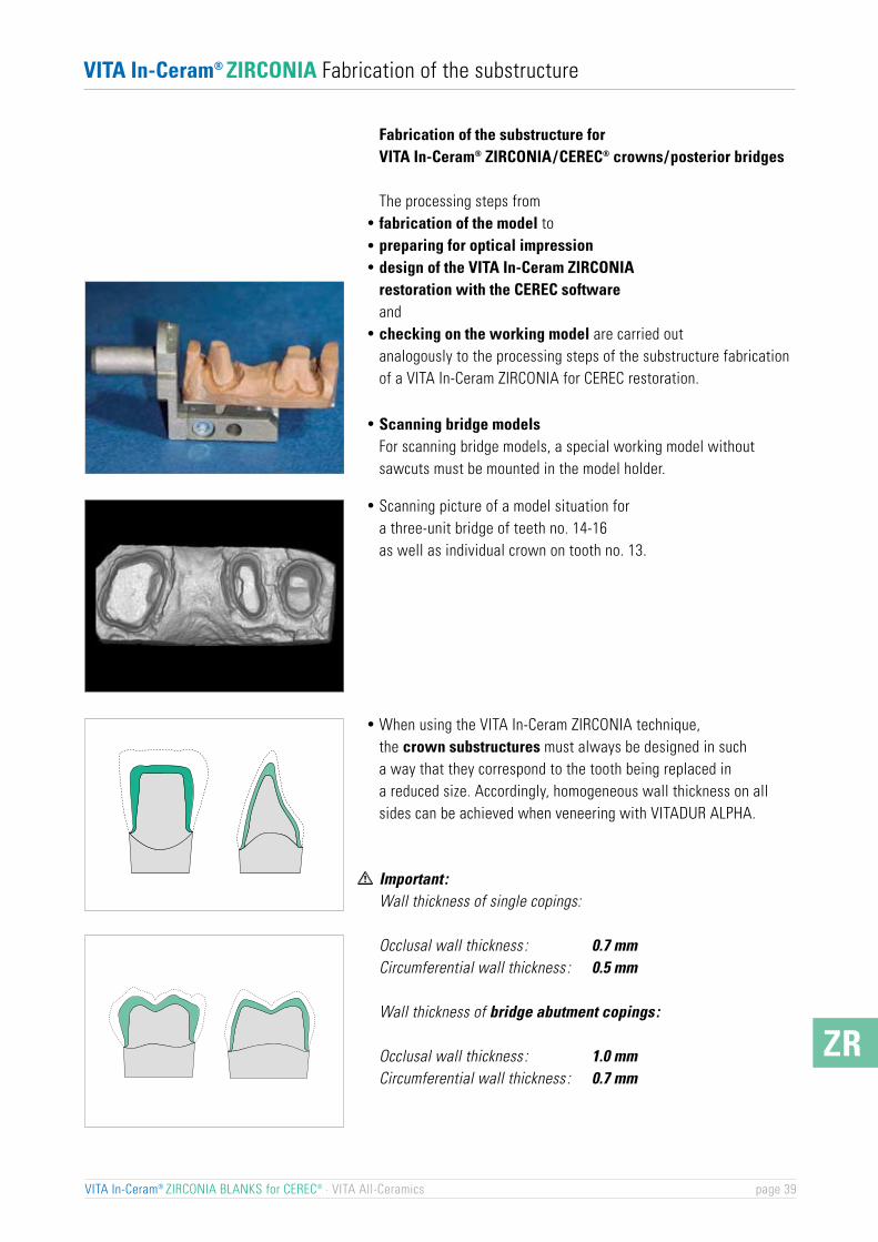
When using the VITA In-Ceram ZIRCONIA technique, the crown substructures must always be designed in sucha way that they correspond to the tooth being replaced ina reduced size. Accordingly, homogeneous wall thickness on allsides can be achieved when veneering with VITADUR ALPHA.
Important :Wall thickness of single copings:
Occlusal wall thickness : 0.7 mmCircumferential wall thickness : 0.5 mm
Wall thickness of bridge abutment copings:
Occlusal wall thickness : 1.0 mmCircumferential wall thickness : 0.7 mm
Fabrication of the substructure forVITA In-Ceram® ZIRCONIA/CEREC® crowns/posterior bridges
The processing steps fromfabrication of the model topreparing for optical impressiondesign of the VITA In-Ceram ZIRCONIArestoration with the CEREC softwareandchecking on the working model are carried outanalogously to the processing steps of the substructure fabricationof a VITA In-Ceram ZIRCONIA for CEREC restoration.
Scanning bridge modelsFor scanning bridge models, a special working model withoutsawcuts must be mounted in the model holder.
Scanning picture of a model situation fora three-unit bridge of teeth no. 14-16as well as individual crown on tooth no. 13.
VITA In-Ceram® ZIRCONIA BLANKS for CEREC® · VITA All-Ceramics page 39
VITA In-Ceram® ZIRCONIA Fabrication of the substructure
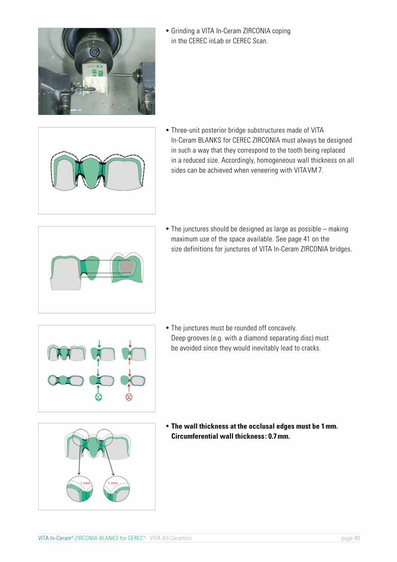
Three-unit posterior bridge substructures made of VITAIn-Ceram BLANKS for CEREC ZIRCONIA must always be designedin such a way that they correspond to the tooth being replacedin a reduced size. Accordingly, homogeneous wall thickness on allsides can be achieved when veneering with VITA VM 7.
Grinding a VITA In-Ceram ZIRCONIA copingin the CEREC inLab or CEREC Scan.
The junctures should be designed as large as possible – makingmaximum use of the space available. See page 41 on thesize definitions for junctures of VITA In-Ceram ZIRCONIA bridges.
The junctures must be rounded off concavely.Deep grooves (e.g. with a diamond separating disc) mustbe avoided since they would inevitably lead to cracks.
The wall thickness at the occlusal edges must be 1 mm.Circumferential wall thickness: 0.7 mm.
VITA In-Ceram® ZIRCONIA BLANKS for CEREC® · VITA All-Ceramics page 40

ZR
Size definitions for junctures ofVITA In-Ceram® ZIRCONIA bridges
Distance A ≤ 6 mmJuncture: 9 mm2
Distance A ≤ 8 mmJuncture: 12.25 mm2
Distance A ≤ 10 mmJuncture: 16 mm2
Distance A ≤ 12 mmJuncture: 20.25 mm2
Distance A ≤ 14 mmJuncture: 25 mm2
Important :When designing the junctures of abutment copings/pontic, the following three criteria must be observed:1. The junctures must be designed in accordance with
the span values listed below.2. Maximum value for height h must be selected.3. Height h should be at least as large as or larger than width w.
Stability and function take priority over aesthetics!
VITA In-Ceram® ZIRCONIA BLANKS for CEREC® · VITA All-Ceramics page 41
Bru
chla
st F
1:2 3:4 1:1 5:4 3:2
Verhältnis Höhe : Breite des Verbinders
F
F
Breite b
Höhe h
F
Ratio of height: width of the connector
Bre
akin
g lo
ad F
Height h
Width b

Adjust the contours using fine-grained diamond abrasivesrotating at low speed and exerting minimum pressure.If required, remove burrs and excess materialat the margin of the structure using rubber polishers.
Check the fit of the ground crown substructureon the die using varnish, lipstic, etc.Remove premature contacts, check accuracyof fit at the preparation border.
Check the material thickness with calipers.Mininum layer thickness: Abutment copings:
circumferential: 0.7 mmocclusal edges: 1.0 mmSingle copings:circumferential: 0.5 mmocclusal: 0.7 mm
Important :Contours must be checked now as no further adjustmentscan be performed after the glass infiltration firing.
Reworking the crown/bridge substructure
Note:Remove the cooling and lubricating fluid DENTATEC from thebridge/crown substructure by means of a cleaning firing.Place substructure on a fibrous pad firing support on firing tray W.
VITA In-Ceram® ZIRCONIA BLANKS for CEREC® · VITA All-Ceramics page 42
Cleaning firing in the VITA VACUMAT®
Predryingtemp. min. °C/min.
Temp.approx. °C min.
VACmin.min.
600 3.00 3.00 33 700 5.00 0.00
�
ZR
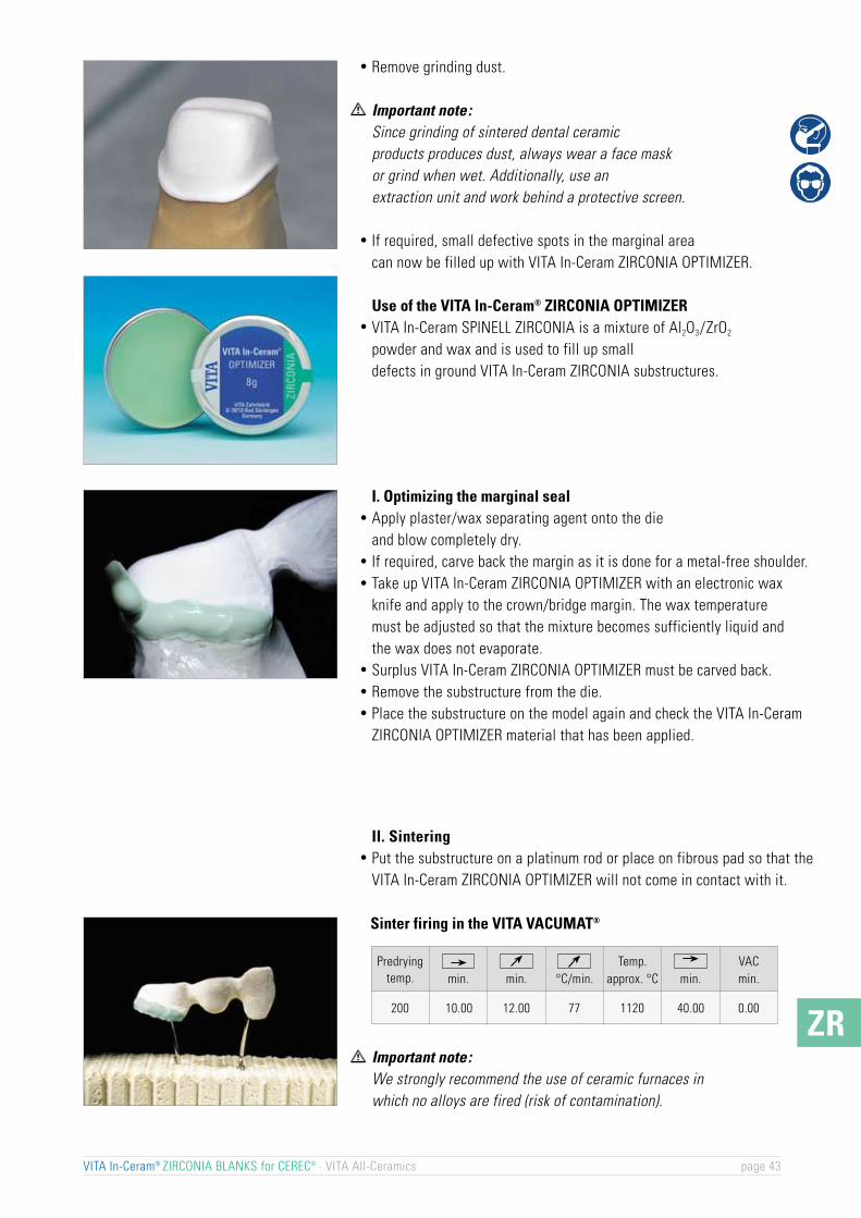
II. SinteringPut the substructure on a platinum rod or place on fibrous pad so that the VITA In-Ceram ZIRCONIA OPTIMIZER will not come in contact with it.
Important note:We strongly recommend the use of ceramic furnaces inwhich no alloys are fired (risk of contamination).
I. Optimizing the marginal sealApply plaster/wax separating agent onto the dieand blow completely dry.If required, carve back the margin as it is done for a metal-free shoulder.Take up VITA In-Ceram ZIRCONIA OPTIMIZER with an electronic waxknife and apply to the crown/bridge margin. The wax temperaturemust be adjusted so that the mixture becomes sufficiently liquid andthe wax does not evaporate.Surplus VITA In-Ceram ZIRCONIA OPTIMIZER must be carved back.Remove the substructure from the die.Place the substructure on the model again and check the VITA In-CeramZIRCONIA OPTIMIZER material that has been applied.
Remove grinding dust.
Important note:Since grinding of sintered dental ceramicproducts produces dust, always wear a face maskor grind when wet. Additionally, use anextraction unit and work behind a protective screen.
If required, small defective spots in the marginal areacan now be filled up with VITA In-Ceram ZIRCONIA OPTIMIZER.
Use of the VITA In-Ceram® ZIRCONIA OPTIMIZERVITA In-Ceram SPINELL ZIRCONIA is a mixture of Al2O3/ZrO2
powder and wax and is used to fill up smalldefects in ground VITA In-Ceram ZIRCONIA substructures.
VITA In-Ceram® ZIRCONIA BLANKS for CEREC® · VITA All-Ceramics page 43
Sinter firing in the VITA VACUMAT®
Predryingtemp. min. °C/min.
Temp.approx. °C min.
VACmin.min.
200 10.00 12.00 77 1120 40.00 0.00

Check on the working model.
Glass infiltrationMix desired In-Ceram ZIRCONIA glass powder with distilled water to obtain a thin consistency.
Apply 1-2 rich coats with a thickness of 1-2mm only to the outersurfaces of the crown or bridge substructure using a brush.
At the beginning, apply only half of the glass powder quantityto the bridge substructure.
The margin must not be covered.
Important :During glass infiltration of bridge substructures on platinum foil,the basal surface of the pontic – in all infiltration firings – must notbe covered with glass powder to enable air to escape from thesubstructure. Correct glass infiltration is only possible if this is ensured.
Note:Apply only small quantities of wet glass powder. Approximatevalue of the required glass quantity: approx. 75 % of the substructureweight so that only minimum sandblasting is required.
VITA In-Ceram® ZIRCONIA BLANKS for CEREC® · VITA All-Ceramics page 44
�
Glass infiltration of the VITA In-Ceram® ZIRCONIA substructures
Checking the substructureThe ground substructure is checked for possible micro-cracksusing the VITA In-Ceram testing liquid.
Should a micro-crack be found, grind the substructure again.

ZR
Cooling down to 400 °C in the closed furnace.
Glass infiltration firing in the VITA VACUMAT®
Alternatively, glass infiltration can also be carriedout in the VITA VACUMAT.
Glass infiltration firing in the VITA INCERAMATPlace the coated crown or bridge substructure onto a piece of platinumfoil 0.1 mm thick for the glass infiltration firing (see page 15). The margins must not come in contact with the platinum foil to preventthe glass from penetrating into the inside of the restoration.
VITA In-Ceram® ZIRCONIA BLANKS for CEREC® · VITA All-Ceramics page 45
VITAPAN® classical/ VITADUR® ALPHA
Determination table for VITA In-Ceram® ZIRCONIA GLASS POWDER
VITA SYSTEM 3D-MASTER® / VITAVM®7Z22N for all VITA SYSTEM 3D-MASTER shades incl. 0M1, 0M2 and 0M3for the reproduction of bleached teeth
A1
Z21N
A2
Z21N
A3
Z22N
A3.5
Z23N
A4
Z23N
B1
Z21N
B2
Z21N
B3
Z22N
B4
Z23N
C1
Z21N
C2
Z22N
C3
Z23N
C4
Z24N
D2
Z22N
D3
Z22N
D4
Z24N
CEREC ALUMINA anterior bridge
Time 1
h:min
0:00 0:00 0:50 2:30 200 1140
Time 4
h:min
Time 3
h:min
Time 2
h:min
Temp. 2
approx. °C
Temp. 1
approx. °C

Important note:It is vital to make sure that the given infiltration temperatureof 1140 °C is adhered to. Infiltration at a temperature which istoo low (e.g. 1100 °C) or too high (e.g. 1180 °C) leads to analteration of the thermal expansion coefficient of the framework.Check the temperature of the furnace with the aid of ceramic testing rings, type PTCR-LTH (available from VITA)! We stronglyrecommend the use of furnaces in which no alloys are fired(risk of contamination).
Important :In case of incomplete infiltration (white spots)the infiltration process must be repeated.
* VAC is not necessarily required but results in higher translucency.
Place the coated crown coping on platinum pin or platinumfoil on firing tray W. The margins must not come incontact with the rods or foil to prevent the glass from penetratinginto the interior of the restoration.
Note:In the case of bridges, the glass infiltration firing must be carriedout on platinum foil which is placed onto firing tray W.
Glass infiltration firing in the VITA VACUMAT®
VITA In-Ceram ZIRCONIA for CEREC posterior bridge,at least two infiltration firing processes on platinum foil
Apply only half of the glass quantity during the first firing process.
VITA In-Ceram® ZIRCONIA BLANKS for CEREC® · VITA All-Ceramics page 46
�
1st infiltration firing (50% of the glass quantity)
2nd infiltration firing (50% of the glass quantity)
Predryingtemp. min. °C/min.
Temp.approx. °C min.
VACmin.min.
600 1.00 27.00 20 1140 40.00 40.00
Predryingtemp. min. °C/min.
ca. Temp.°C min.
VACmin.min.
600 1.00 27.00 20 1140 40.00 40.00
VITA In-Ceram ZIRCONIA for CEREC crown, at least one glassinfiltration firing process
Predryingtemp. min. °C/min.
ca. Temp.°C min.
VACmin.min.
600 1.00 27.00 20 1140 30.00 33.00
*
*
*

ZR
Remove excess glassRemove excess glass with a coarse-grained diamondinstrument or HEATLESS.
Attention: Glass dust consists of sharp particles.Always wear protective glasses and a face mask, use anextraction unit and work behind a protective screen.
Important :Do not grind down to the substructure.
Sandblast residual ZIRCONIA glass in the sandblasting unit(disposable abrasive blasting technique) using Al2O3 (30-50 µm)at a pressure of 4 bars (cervical: 2.5 bars).
Finished VITA In-Ceram ZIRCONIA substructureon the working model.
Glass control firing in the VITA VACUMAT®
Glass that has escaped must be removed by sandblasting again.
Important :For safety’s sake this process must be repeated againuntil no more glass is visible. This must always be followedby a glass control firing.
Infiltrated VITA In-Ceram ZIRCONIA substructure.
VITA In-Ceram® ZIRCONIA BLANKS for CEREC® · VITA All-Ceramics page 47
Glass control firing on fibrous pads in the firing support W as follows :
Predryingtemp. min. °C/min.
Temp.approx. °C min.
VACmin.min.
600 0.00 5.00 80 1000 5.00 0.00
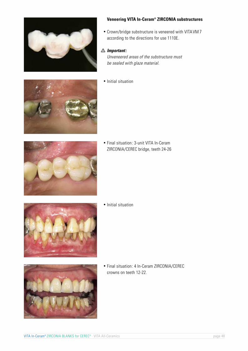
Veneering VITA In-Ceram® ZIRCONIA substructures
Crown/bridge substructure is veneered with VITA VM 7according to the directions for use 1110E.
Important :Unveneered areas of the substructure mustbe sealed with glaze material.
Final situation: 3-unit VITA In-CeramZIRCONIA/CEREC bridge, teeth 24-26
Initial situation
Initial situation
Final situation: 4 In-Ceram ZIRCONIA/CERECcrowns on teeth 12-22.
VITA In-Ceram® ZIRCONIA BLANKS for CEREC® · VITA All-Ceramics page 48

ZR
VITA In-Ceram® ZIRCONIA BLANKS for CEREC® · VITA All-Ceramics page 49
Optimizing with VITA In-Ceram® ZIRCONIA OPTIMIZER (light-green wax mixture) in the VITA VACUMAT®
Predryingtemp.
VITA VACUMAT
Cleaning firing*
min. °C/min.Temp.
approx. °C min.VACmin.min.
600 3.00 3.00 33 700 5.00 0.00
VITA VACUMATmin. °C/min.
Temp.approx. °C min.
VACmin.min.
600Glass control firing* 0.00 5.00 80 1000 5.00 0.00
Firing charts VITA In-Ceram® ZIRCONIA for CEREC®
200 10.00 12.00 77 1140 40.00 0.00
Predryingtemp.
Predryingtemp.
1st dentine firing 500 6.00 7.27 55 910 1.00 7.27
2nd dentine firing 500 6.00 7.16 55 900 1.00 7.16
Glaze firing 500 0.00 5.00 80 900 1.00 0.00
Sinter firing ZIRCONIA OPTIMIZER
500 0.00 5.00 80 900 1.00 0.00Glaze firing with
VITA Akzent FLUID
500 6.00 7.38 55 920 1.00 7.38VITAVM 7 EFFECT
LINER firing
500 4.00 5.00 80 900 1.00 0.00Glaze firing with
VITA Akzent glaze
500 6.00 7.27 55 900 1.00 0.00Glaze firing with VITASHADING PASTE glaze
500 4.00 6.00 55 830 1.00 6.00Corrective firing with
VITAVM 7 CORRECTIVE
Glass infiltration firing VITA In-Ceram® ZIRCONIA for CEREC® crown and posterior bridge in the VITA INCERAMAT
Veneering of VITA In-Ceram® ZIRCONIA for CEREC® restoration with VITAVM®7 in the VITA VACUMAT®
Glass control firing VITA In-Ceram® ZIRCONIA for CEREC® restoration in the VITA VACUMAT®
min. min. °C/min.Temp.
approx. °C min.VACmin.
VITA VACUMAT
VITA INCERAMAT
0:00 0:50 2:30 200 1140
Time 1h:min
Time 4h:min
Time 3h:min
Time 2h:min
Temp. 3approx. °C
Temp. 1approx. °C
Infiltration 0:00
Abkühlen bis 400 °C bei geschlossenem Ofen
Cleaning firing is generallycarried out prior to optimizingand glass infiltration.
*
Repeat after sandblasting*

VITA In-Ceram® ZIRCONIA BLANKS for CEREC® · VITA All-Ceramics page 50
For personal notes

VITA Zahnfabrik is certified according to the MedicalDevice Directive and the following products listed in thesedirections for use bear the mark
VITA In-Ceram® ALUMINA BLANKS for CEREC®
VITA In-Ceram® SPINELL BLANKS for CEREC®
VITA In-Ceram® ZIRCONIA BLANKS for CEREC®
VITA In-Ceram® ALUMINA OPTIMIZERVITA In-Ceram® SPINELL OPTIMIZERVITA In-Ceram® ZIRCONIA OPTIMIZERVITA In-Ceram® ALUMINA GLASS POWDERVITA In-Ceram® SPINELL GLASS POWDERVITA In-Ceram® ZIRCONIA GLASS POWDERVITADUR® ALPHAVITAVM®7
The following product requires hazard identification:
VITA In-Ceram® testing liquid, 6 ml
flammable
Please refer to the safety data sheet for more detailed information.
These directions for use were prepared with the support of
Dental-Design Giordano Lombardi, CH-Zürich,Dr. Alessandro Devigus, CH-Bülach,Dentallabor Vanik Kaufmann-Jinoian, CH-Liestal,Dr. Andres Baltzer, CH-Rheinfeldenund Dr. Andreas Kurbad, D-Viersen
VITA In-Ceram® ZIRCONIA BLANKS for CEREC® · VITA All-Ceramics page 51
0124
The VITA In-Ceram all-ceramic materials are integratedin the VITA SYSTEM 3D-MASTER. Shade compatibility withall VITA materials is ensured.
3D - MasterVita System
Equipment All-Ceramics
Serv
ice
VeneeringMaterials
Teeth
The unique VITA SYSTEM 3D-MASTERallows the systematic determination and reproductionof all natural tooth shades.
Please note: Our products should be used according to the working instructions. We cannot beheld liable for damages resulting from incorrect handling or usage. The user is furthermore obligedto check the product before use with regard to its suitability for the intended area of applications.We cannot accept any liability if the product is used in conjunction with porcelains and equipmentfrom other manufacturers which are not compatible or not authorized for use with our product.Furthermore, our liability for the correctness of this information is independent of the legal groundand, in as far as legally permissible, is limited to the invoiced value of the goods suppliedexcluding turnover tax. In particular, as far as legally permissible, we do not assume any liabilityfor profit loss, for indirect damages, for consequential damages or for claims of third partiesagainst the purchaser. Claims for damages based on fault liability (culpa in contrahendo, breach ofcontract, unlawful acts, etc.) can only be made in the case of intent or gross negligence.Date of issue of these directions for use: 09/04After the publication of these directions for use any previous versions become obsolete.
VITA Zahnfabrik H. Rauter GmbH & Co.KGPostfach 1338 · D-79704 Bad Säckingen . GermanyTel. +49/ 7761/562-222 · Fax +49/ 7761/562-446www.vita-zahnfabrik.com · [email protected]
1047
E-0
904
(3.)
KF