Visucam 200 si 500.pdf
96
sfpr`^j aáÖáí~ä cìåÇìë `~ãÉê~ Esfpr`^j OMM ~åÇ sfpr`^j RMMF Documentation set
-
Upload
mirela-marinescu -
Category
Documents
-
view
1.519 -
download
205
Transcript of Visucam 200 si 500.pdf

sfpr`^j=aáÖáí~ä=cìåÇìë=`~ãÉê~=Esfpr`^j=OMM=~åÇ=sfpr`^j=RMMF=
Documentation set


000000-1781-493_Inhalt0_GB_070311
`çåíÉåí=
User manual VISUCAM Digital Fundus Camera (VISUCAM 200 and VISUCAM 500)
[000000-1781-493_GA_GB_230211]
Addendum to the document set
Notes on the use of the optional MPD module
[000000-1781-493_AddGA01_GB_220710]
Notes on and conditions of use for the
remote maintenance tool
[000000-1305-000_AddGA01_GB_040610]
Microsoft Software License Terms
[LT_XP_PRO_embedded_080807]
^åä~ÖÉå VISUCAM 200/VISUCAM 500 - Settings
[000000-1781-493_AddGA02_GB_070311]
VISUCAM 200 - Quick Instructions
[000000-1769-898_KurzGA01_GB_070311]
VISUCAM 500 - Quick Instructions
[000000-1781-493_KurzGA01_GB_070311]
Fundus Photography - Advice and Tips
[000000-1305-000_KurzGA02_GB_240309]
1
3
4
2


000000-1781-493_Inhalt1_GB
`çåíÉåí=
User manual VISUCAM Digital Fundus Camera (VISUCAM 200 and VISUCAM 500)
[000000-1781-493_GA_GB_230211]
1


sfpr`^j=aáÖáí~ä=cìåÇìë=`~ãÉê~=Esfpr`^j=OMM=~åÇ=sfpr`^j=RMMF==User manual
=
000000-1781-493_GA_GB_230211
User manual VISUCAM Digital Fundus Camera 000000-1781-493_GA_GB_230211 23.02.2011 © 2011, Carl Zeiss Meditec AG, Jena All rights reserved in the event of granting of patents or registration as a utility patent. All names of companies and products cited in this manual may be trademarks or registered trademarks. Third party products are cited for information purposes only. This does not represent approval or recommendation of these products. Carl Zeiss Meditec AG accepts no liability for the performance or use of such products. Microsoft Windows® is a registered trademark of Microsoft Corporation, Inc. VISUCAM® and VISUPAC® are trademarks of Carl Zeiss Meditec AG. Other brand names, software and hardware names used in this user manual are generally subject to trademark or patent protection. The quoting of products is for informational purposes only and does not represent a trademark misuse. This user manual is protected by copyright. Unless expressly authorized in writing, dissemination, duplication or other commercial exploitation of this document or communication of its contents or parts of it is not permitted. In case of infringement, the violator may be liable to pay compensation for damages. Specifications due to technical developments are subject to change. This manual is not subject to the revision service. Please contact the manufacturer or authorized dealer to request the latest edition of the manual.

Contents
000000-1781-493_GA_GB_230211
1
`çåíÉåíë=
Contents................................................................................... 1
Notes on the user manual ........................................................ 3 Purpose and availability of documentation ...................................................3 Questions and comments ..............................................................................3 Explanation of symbols used.........................................................................4
Package check list.................................................................... 5
Country-specific information and labels ................................... 6 Classification/Manufacturer's declaration .....................................................6 DICOM Conformance Statement ...................................................................6 Indication for use ..........................................................................................7 Intended user profile.....................................................................................8 Disposal of the product.................................................................................9 Labels..........................................................................................................10
Performance specifications .................................................... 12 Functional description.................................................................................12 Service life...................................................................................................13
Description of the device........................................................ 14
Installation ............................................................................. 17 Notes on installation and use......................................................................17 Unpacking...................................................................................................18 VISUCAM installation.................................................................................................. 19 Electrical connection ................................................................................................... 19 Power isolation transformer for external devices........................................21
Daily use ................................................................................ 23 Switching on ...............................................................................................24
Operation............................................................................... 25 General........................................................................................................26 Operation using the control panel on the instrument base .........................27 Operation via keyboard and mouse ............................................................28 Screen layout ..............................................................................................29 Overview of menus and buttons .................................................................31

Contents
000000-1781-493_GA_GB_230211
2
Shutting down ........................................................................34 Switching off the instrument ......................................................................34
Notes on angiography.............................................................36 Angiography using the VISUCAM 500.........................................................36
Maintenance and care.............................................................37 Fault remedy ...............................................................................................37 Replacing the blinking diode of the fixation lamp.......................................38 Replacing the fuses .....................................................................................39 Replacing the power isolation transformer fuse ..........................................................39 Replacing the basic unit fuse .......................................................................................40 Maintenance ...............................................................................................41 Operating the online remote maintenance module.....................................................41 Operating the offline remote maintenance module ....................................................42 Care and cleaning........................................................................................................44 Data backup................................................................................................49 Safety inspections .......................................................................................49
Optional accessories................................................................50 Mounting the monitor holder on an instrument table.................................50 Demonstration eye......................................................................................51 USB flash drive............................................................................................51 Stereo viewer..............................................................................................52 Printer.........................................................................................................52 Installation of a network printer..................................................................................52
Technical data.........................................................................54
Electromagnetic compatibility.................................................56
Abbreviations/Glossary............................................................60
Figures/Tables .........................................................................61
Index.......................................................................................62

Notes on the user manual
000000-1781-493_GA_GB_230211
3
kçíÉë=çå=íÜÉ=ìëÉê=ã~åì~ä=
Purpose and availability of documentation
This user manual explains the safety precautions, functions, usage, performance parameters and measures for care and maintenance of the VISUCAM.
Correct operation of the system is imperative for its safe and successful function. You should therefore ensure that you are thoroughly familiar with this user manual before setting up and using the VISUCAM the first time. Please also observe the operating instructions for other equipment used with this instrument.
The user manuals and other documentation enclosed with the VISUCAM should be kept accessible to users at all times to ensure that the information required for use of the VISUCAM is readily available.
Questions and comments
If you have any questions or comments concerning this user manual or the VISUCAM, please contact Carl Zeiss Meditec customer service or your local dealer.

Notes on the user manual
000000-1781-493_GA_GB_230211
4
Explanation of symbols used
The symbols used in this user manual refer to important safety information which may warn against possible health risks or fatal injuries and contain useful notes. Whenever you see these symbols, read the accompanying information carefully and observe all safety notes and information in this user manual and on device labels.
WARNING
Indicates a hazardous situation which may result in fatal or serious bodily injury if the appropriate safety precautions are not heeded.
CAUTION
Indicates a hazardous situation which may result in minor injury if the appropriate safety precautions are not heeded.
CAUTION - PROPERTY DAMAGE
Indicates possible device damage if the appropriate safety precautions are not heeded.
Information, hints and advice for a better understanding of the instructions to be observed in the operation of the instrument.

Package check list
000000-1781-493_GA_GB_230211
5
m~Åâ~ÖÉ=ÅÜÉÅâ=äáëí=
The following accessories are supplied with the VISUCAM:
• Document set
• 19" TFT monitor
• Keyboard
• Mouse
• Power isolation transformer
• VISUPAC 4.x installation CD with license for one PC
• Power cable
• LensPen cleaning pen
• Fixation lamp (only for VISUCAM 500)
Country-specific information and labels
000000-1781-493_GA_GB_230211
6
`çìåíêóJëéÉÅáÑáÅ=áåÑçêã~íáçå=~åÇ=ä~ÄÉäë=
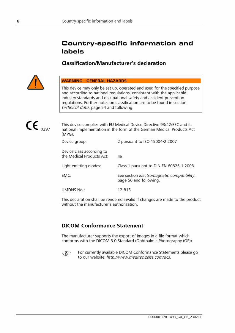
Classification/Manufacturer's declaration
WARNING - GENERAL HAZARDS
This device may only be set up, operated and used for the specified purpose and according to national regulations, consistent with the applicable industry standards and occupational safety and accident prevention regulations. Further notes on classification are to be found in section 11Technical data, page 1154 and following.
This device complies with EU Medical Device Directive 93/42/EEC and its national implementation in the form of the German Medical Products Act (MPG).
Device group: 2 pursuant to ISO 15004-2:2007 Device class according to the Medical Products Act: IIa
Light emitting diodes: Class 1 pursuant to DIN EN 60825-1:2003
EMC: See section Electromagnetic compatibility, page 1156 and following.
UMDNS No.: 12-815
This declaration shall be rendered invalid if changes are made to the product without the manufacturer’s authorization.
DICOM Conformance Statement
The manufacturer supports the export of images in a file format which conforms with the DICOM 3.0 Standard (Ophthalmic Photography (OP)).
For currently available DICOM Conformance Statements please go to our website: http://www.meditec.zeiss.com/dcs.
0297

Country-specific information and labels
000000-1781-493_GA_GB_230211
7
Indication for use
The VISUCAM Digital Fundus Camera is suitable for photographing, displaying and storing data relating to the retina and surrounding parts of the eye being examined under mydriatic and non-mydriatic conditions. These photographs assist with the diagnosis and follow-up of eye diseases, which can be visually monitored and photographically documented.
CAUTION - GENERAL HAZARDS
Use of mydriatics may occasionally result in side effects which may include life or sight-threatening reactions such as acute glaucoma, cardiac arrhythmias, increased intraocular pressure, and sudden high blood pressure. The lowest possible dose for dilation of the pupil should be used. Please also observe manufacturer's specifications.
CAUTION - RISK OF OPERATING ERRORS
Do not use the VISUCAM in patients with the following conditions:
• Unable to follow the instructions of the user
• Unable to sit upright in front of the instrument
• Forehead or chin injuries that prevent the head from being supported on the head/chin rest
Allow for serious restrictions in the use of the VISUCAM for the following patient groups:
• Complete or partial coverage of the cornea caused by palpebral fissure which is closed or too small
• Unable to steadily fixate the fixation lights with the eye under examination (e.g. in the case of nystagmus, tremor, Parkinson's disease, extremely poor visual acuity, lack of concentration)
• Non-foreseeable influence of wearing contact lenses (remove contact lenses before exposure)
• Patients with a small pupil

Country-specific information and labels
000000-1781-493_GA_GB_230211
8
Intended user profile
CAUTION - RISK OF OPERATING ERRORS
The device may only be installed, operated, used and maintained by persons who have been properly trained or who have the required knowledge and experience to do so. Please adhere to the additional national qualification guidelines applicable in your country.
Persons who operate the VISUCAM must have a basic knowledge of ophthalmic examination and diagnosis methods. It is recommended that the VISUCAM operator has the following essential skills:
Ophthalmo photographer, optometrist, MTA and staff who prepare images using the VISUCAM
• Completed training as optician, optometrist, ophthalmo-photographer or medical-technical assistant
• Experience with the Microsoft Windows operating system and applications based on it
• Knowledge of current ophthalmic diagnostic procedures and their examination results
• Knowledge of the effects of incorrect or inaccurate examination results on the therapy
• Possible consistency checks against other examination results
• Practical experience in handling ophthalmic diagnostic devices
• Experience in calming and explaining to patients, in particular older population
Physicians who prepare images and diagnoses with the VISUCAM
In addition to the above skills, the operator should have completed training as an eye specialist in order to recognize and evaluate the different findings, in particular:
• Diagnostically relevant findings in fundus color images or red-free photographs
• Diagnostically relevant findings in the early, medium and late phase of fluorescein angiograms
• Skills in the evaluation of fundus autofluorescence images and indocyanine angiograms
Country-specific information and labels
000000-1781-493_GA_GB_230211
9
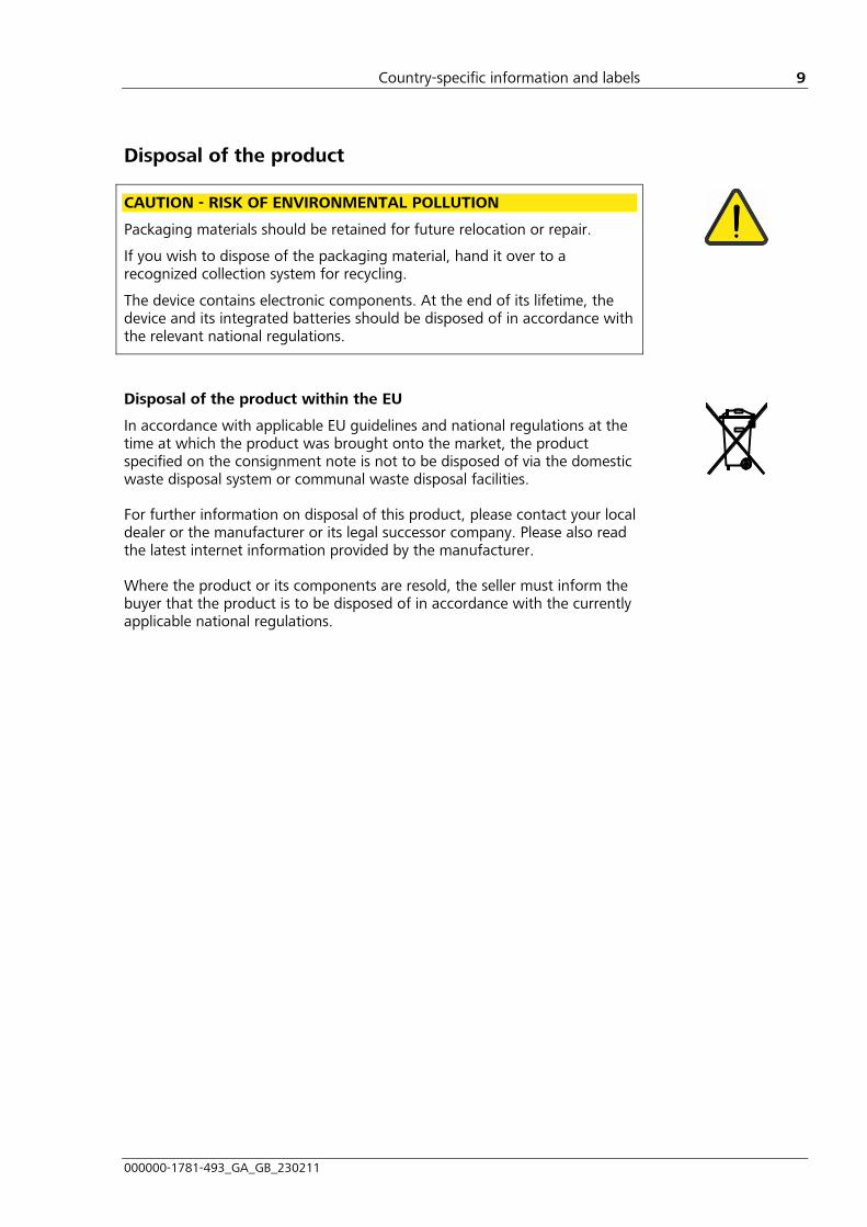
Disposal of the product
CAUTION - RISK OF ENVIRONMENTAL POLLUTION
Packaging materials should be retained for future relocation or repair.
If you wish to dispose of the packaging material, hand it over to a recognized collection system for recycling.
The device contains electronic components. At the end of its lifetime, the device and its integrated batteries should be disposed of in accordance with the relevant national regulations.
Disposal of the product within the EU
In accordance with applicable EU guidelines and national regulations at the time at which the product was brought onto the market, the product specified on the consignment note is not to be disposed of via the domestic waste disposal system or communal waste disposal facilities.
For further information on disposal of this product, please contact your local dealer or the manufacturer or its legal successor company. Please also read the latest internet information provided by the manufacturer.
Where the product or its components are resold, the seller must inform the buyer that the product is to be disposed of in accordance with the currently applicable national regulations.

Country-specific information and labels
000000-1781-493_GA_GB_230211
10
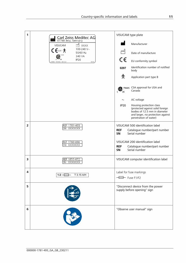
Labels
Fig. 1 Labeling of VISUCAM
Country-specific information and labels
000000-1781-493_GA_GB_230211
11
VISUCAM type plate
1
0297
IP20
Manufacturer
Date of manufacture
EU conformity symbol
Identification number of notified body Application part type B
CSA approval for USA and Canada AC voltage Housing protection class (protected against solid foreign bodies of 12.5 mm in diameter and larger, no protection against penetration of water)
VISUCAM 500 identification label
REF Catalogue number/part number SN Serial number
2
VISUCAM 200 identification label
REF Catalogue number/part number SN Serial number
3
VISUCAM computer identification label
4
1-2 T 3.15 A/H
Label for fuse markings
Fuse F1/F2
5
"Disconnect device from the power supply before opening" sign
6
"Observe user manual" sign

Performance specifications
000000-1781-493_GA_GB_230211
12
mÉêÑçêã~åÅÉ=ëéÉÅáÑáÅ~íáçåë=
Functional description
The VISUCAM allows the fundus of the eye to be viewed and documented with the pupil in a naturally or medicinally-induced dilated state. Easy-to-use camera operation ensures quick results. It is particularly suitable for routine use and screening. The fundus is evaluated on the basis of a flash photograph. Image capture and display is fully digital.
The VISUCAM employs the ophthalmoscope principle of the modern fundus camera and images the fundus of the eye at a field angle of 45° or 30°. The instrument operates in non-contact mode. Non-mydriatic operation is based on positioning and focusing of the camera using infrared light. This means that the use of pupil-dilating drops is not necessarily required. This does, however, require a naturally dilated pupil, such as is achieved in a darkened room. The non-mydriatic technique is not suitable for fluorescein angiography (VISUCAM 500 only); in this case medicinally-induced dilation is required.
Infrared diodes are used as a light source for setting up the camera. The working distance is set up using two working distance dots and the fundus brought into focus using a pair of coincident lines. A flashbulb is used to record images.
The VISUCAM 200 supports capture modes Color, G (green), R (red) and B (blue). VISUCAM 500 additionally supports capture modes FA (fluorescein angiography) and optionally AutoFluo (auto-fluorescence) and ICGA (indocyanine green angiography). The settings are controlled via the live set-up image displayed on the monitor.
After image capture has been triggered, the image is displayed on the monitor in place of the live set-up image and saved automatically. The digital image sensor has a resolution of five megapixels.
The VISUCAM includes an intuitive software interface for database-supported patient and image data administration. Images can be displayed, printed and exported and patient data created and adapted simply at any time. The software also includes a basic image optimization feature for printouts.

Performance specifications
000000-1781-493_GA_GB_230211
13
As for standard commercial digital cameras, the VISUCAM is only able to store images for a limited time period, depending on the limited hard disk capacity. Images can be stored long term using an external archiving system (e.g. VISUPAC or FORUM systems) or by retaining the printouts. Image data can be exported in BMP, JPEG, TIFF or DICOM formats. The DICOM format additionally permits the transfer of patient-relevant information.
To export and copy data to another computer system, a network connection is recommended. The integrated DVD/CD burner allows data to be transferred to DVD or CD. A USB flash drive is also available.
Service life
WARNING - GENERAL HAZARDS
The development, production and maintenance of this device, together with associated risks, are based on an expected service life of eight years, assuming that the device is serviced at the specified intervals.
Modifications to the product or failure to follow the manufacturer’s instructions may substantially reduce the expected service life and significantly increase the risks associated with the use of this device.
It is the responsibility of the institution operating this product to follow the manufacturer’s instructions and to decide on the risk/benefit ratio upon expiration of the expected service life or maintenance and inspection intervals specified by the manufacturer.

Description of the device
000000-1781-493_GA_GB_230211
14
aÉëÅêáéíáçå=çÑ=íÜÉ=ÇÉîáÅÉ=
1 Cap for fixation lamp
2 Fixation lamp, freely (3D) movable (not supplied with VISUCAM 200)
3 Headrest with vertically adjustable chin rest, forehead support and mount for fixation lamp
4 Monitor for observation of the patient’s eye and display of instrument information
5 Keyboard and mouse for the entry of patient data and operation of the device
6 Instrument base
7 Computer base unit with head rest
8 Camera head containing illumination and viewing system with image sensors
Fig. 2 Basic instrument design
Description of the device
000000-1781-493_GA_GB_230211
15
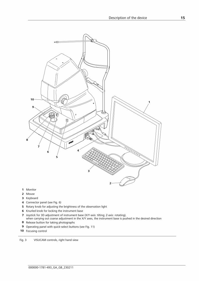
1 Monitor
2 Mouse
3 Keyboard
4 Connector panel (see 11Fig. 6)
5 Rotary knob for adjusting the brightness of the observation light
6 Knurled knob for locking the instrument base
7 Joystick for 3D adjustment of instrument base (X/Y-axis: tilting; Z-axis: rotating), when carrying out coarse adjustment in the X/Y axes, the instrument base is pushed in the desired direction
8 Release button for taking photographs 9 Operating panel with quick-select buttons (see 11Fig. 11)
10 Focusing control
Fig. 3 VISUCAM controls, right hand view

Description of the device
000000-1781-493_GA_GB_230211
16
1 Sleeve nut for fixation lamp
2 Patient forehead support
3 Red marks (suitable patient eye level for optimum photography)
4 Front lens (exit aperture for LED illumination; with protective front lens cap)
5 Patient chin rest
6 Fastening pins for paper pads
7 Knurled knob for vertical adjustment of chin rest
8 DVD burner
Fig. 4 VISUCAM controls, left hand view

Installation
000000-1781-493_GA_GB_230211
17
fåëí~ää~íáçå=
Notes on installation and use
WARNING - GENERAL HAZARDS
The device may not be stored or operated in ambient conditions other than those prescribed (see section 11Technical data on page 1154).
The device should be set up so that the power cable can be disconnected from the power supply quickly and easily without any tools.
WARNING - RISK OF ELECTRIC SHOCK
Additional extension cables or portable multiple sockets may not be used.
The electrical installation must conform to IEC 60364-7-710 or the applicable national regulations. This includes the existence of a ground fault circuit interrupter (GFCI).
To avert the risk of an electric shock this device may only be connected to a power supply with a protective earth conductor.
Ensure that the power supply plug is suitable and certified for the local connection. If the supplied power cable must be replaced, at least the following specifications must be adhered to:
• Protective earth conductor resistance maximum 0.2 Ohm
• Local certification of the power cable for connection to medical devices
• Device plug C19 conforming to IEC 60320
• Cross-section at least 0.75 mm²/AWG 18 Hospital Grade design for specific countries (e.g. USA, Canada) (For cables > 2.5 m the cross-section must be increased to 1.5 mm²)
WARNING - FIRE HAZARD
The device is not suitable for operation in explosion risk areas (e.g. combustible mixture of anaesthetic, cleaning or disinfecting agents with air, oxygen or nitrous oxide).
The electrical installation must conform to IEC 60364-7-710.
The data concerning power consumption on the type plate must be taken into account in the selection of overcurrent protection.
The device should be switched off and unplugged from the power supply before replacing the fuse.

Installation
000000-1781-493_GA_GB_230211
18
CAUTION - PROPERTY DAMAGE
Do not store or use this device in damp rooms. Do not expose the device to water splashes, dripping or sprayed water.
CAUTION - PROPERTY DAMAGE
Handle with care; the instrument should not be lifted or carried by the instrument head!
Unpacking
The user will usually carry out the following procedures:
• Unpack the accessories cardboard box (keyboard, mouse, etc.).
• Remove plastic compression straps from the instrument box lift box straight up.
• Remove the compression strap and foam.
• Place the device on the table.
• Remove the red transportation locking device.
• If used, insert the fixation lamp into the mount and secure it in place using the sleeve nut (1, 11Fig. 4).
During transport the device should be carried as shown in Fig. 5.
Fig. 5 Transport of VISUCAM

Installation
000000-1781-493_GA_GB_230211
19
VISUCAM installation
CAUTION - DANGER FROM FALLING PARTS
When selecting a suitable table, ensure that the combination of table and instrument is stable up to an angle of tilt of 10°. Furthermore, the table must be designed for 4 times the weight of the device configuration. If the table is on castors, these must have a locking device.
The VISUCAM must be set on the instrument table so that all four rubber feet sit securely on the surface at a sufficient distance from the table edge.
Electrical connection
WARNING - RISK OF ELECTRIC SHOCK
If connecting external devices to the interfaces of the VISUCAM, the operator must ensure to meet the safety requirements as per IEC 60601-1-1 (medical electrical systems)!
For connection to a LAN, a network isolator must be installed (disconnection voltage at least 4 kV).
The printer must be set up outside the patient environment (1.5 m from the patient's seat at the instrument), operated with a network isolator and plugged into a separate socket. The user may not touch the printer and patient simultaneously.
If the printer is to be operated in the patient environment, it must be connected via an isolating transformer.
A USB isolator (disconnection voltage at least 4 kV) must be used for data exchanged via external USB devices with separate power supply. The USB isolator may not be powered by a separate power supply.
CAUTION - RISK OF OPERATING ERRORS
Only software authorized by Carl Zeiss Meditec may be used in this instrument.
The device may only be connected to private networks which are protected from public networks (Internet) by firewalls conforming to the latest technical standards!

Installation
000000-1781-493_GA_GB_230211
20
• Connect the monitor cable (DVI/VGA) to the monitor port (5, 11Fig. 6) of the VISUCAM.
• Connect the optional printer (if not a network printer) to a free USB port (4, 11Fig. 6) on the VISUCAM.
Further notes on installation of a network printer are to be found in section 11Installation of a network printer, page 1152 and following.
• Connect the keyboard and mouse to the respective sockets (6 and 2, 11Fig. 6).
• Insert the USB flash drive into a free USB port (4, 11Fig. 6) on the VISUCAM.
The VISUCAM supports the USB version 2.0.
1 Power switch
2 Mouse port (with USB/PS2 adapter)
3 Network connector
4 4 USB ports
5 Monitor port
6 Keyboard port
7 ~ Power input
Fig. 6 Connection panel of the VISUCAM
• Connect the monitor and printer power cables to the power isolation transformer (see 11Fig. 8).
• Connect the basic unit and power isolation transformer using the supplied power cord to separate, firmly installed mains sockets.
• The external printer and monitor units are connected and switched on via the power isolation transformer.
Please also see the operating manual for the monitor and printer.

Installation
000000-1781-493_GA_GB_230211
21
Power isolation transformer for external devices
WARNING - RISK OF ELECTRIC SHOCK
Always connect all peripheral devices to the power isolation transformer. Components other than the system components described may not be connected to the power isolation transformer or instrument table. Non-compliance represents a violation of the regulations for use of medical devices under IEC 60601-1-1.
The power isolation transformer may not be placed on the floor.
The power isolation transformer for external units is available for mains voltages of 120 V or 240 V.
1 Power input with fuses
2 Power switch
Fig. 7 Power isolation transformer, 120 V or 240 V, front view
1 Appliance socket 1 Appliance socket
2 Earthing contact socket 2 HOSPITAL GRADE socket
Fig. 8 Power isolation transformer, 240 V, rear view
Fig. 9 Power isolation transformer,
120 V, rear view

Installation
000000-1781-493_GA_GB_230211
22
Use the four enclosed M4 screws to fasten the power isolation transformer to the instrument table. For this purpose a fastening plate with four drill holes (1, 11Fig. 10) has been pre-mounted on the power isolation transformer by the manufacturer.
1 Four drill holes on the fastening plate of the power isolation transformer
Fig. 10 Mounting the power isolation transformer

Daily use
000000-1781-493_GA_GB_230211
23
a~áäó=ìëÉ=
WARNING - GENERAL HAZARDS
Prior to using the instrument, the user must ensure that it is in a good condition and fully functioning. Furthermore, the user must follow the instructions in the user manual.
The following inspections must be carried out each working day prior to use:
• Visual inspection of the housing, labels, user manual, accessories and power cable to ensure that they are present and intact. If parts are missing or damage is visible, the instrument should not be used and should be taken out of service.
• The ventilation slits in the casing should not be covered or otherwise obstructed!
WARNING - RISK OF ELECTRIC SHOCK
Please take care that the following operational requirements are met each time before using the instrument and maintained throughout further operation:
• Use the power cable supplied with the instrument. If the instrument is mounted on an instrument table, it will be powered through this table. If using a table not approved by Carl Zeiss Meditec AG, the user is solely responsible for ensuring the electrical safety of the instrument.
• The power plug must be inserted into a power outlet with an intact protective ground connection.
• Cables and plugs may only be used if they are in perfect condition.

Daily use
000000-1781-493_GA_GB_230211
24
Switching on
• Use the power isolation transformer (2, 11Fig. 7) to switch on the external devices.
• Switch on the VISUCAM using the power switch (1, 11Fig. 6) on the basic unit.
• When the device is turned on at the power switch, it will run through an internal test. Once this has been successfully completed, the Patient Manager user interface is displayed and the device is ready for operation.
To restart the system after it has been inadvertently switched off at the power switch during operation or after a system crash, switch the device back on at the power switch. Note any error messages displayed. After restarting, run a function test in the Capture mode user interface.
Some of the operating parameters are set to factory defaults and can be changed in the VISUCAM software’s Settings menu (see Software description file).

Operation
000000-1781-493_GA_GB_230211
25
léÉê~íáçå=
WARNING - RISK OF OPTICAL RADIATION
Because prolonged intense light exposure can damage the retina, the use of the device for ocular examination should not be unnecessarily prolonged, and the brightness settings should not exceed what is needed to provide clear visualization of the target structures.
The light emitted by this device may be harmful. The risk of eye damage increases with the length of exposure to rays and the number of single flashes. Exposure exceeding 370 single flashes at max. flash light level will result in exceeding the reference value for hazard.
CAUTION - GENERAL HAZARDS
The patient should not touch the instrument with his/her hands. In particular, the instrument should not be used as a support or an aid for standing up.
CAUTION - RISK OF FALSE DIAGNOSIS
When operating radio devices or components for radio transmission, observe the distances recommended in Section 11Electromagnetic compatibility, page 1156 and following. If the distance is not observed, electro-magnetic disturbances may result in artefacts in the images.
CAUTION - HAZARD DUE TO MOVING PARTS
When lowering the instrument table always ensure that no objects are within the movement range of the tabletop. Before operating the rocker switch, ensure that there are no objects or body parts in the movement range of the tabletop or its extensions.
Users should not rely solely on images made using the VISUCAM in making decisions regarding diagnosis or other therapeutic procedures, but should rely on their own expertise and judgment.

Operation
000000-1781-493_GA_GB_230211
26
General
The VISUCAM computer system uses the Microsoft Windows XP operating system. For safety reasons, the operating system is not accessible to the user.
The VISUCAM user interface is used in the same way as Microsoft Windows. This includes working with the mouse, the use of buttons, dialog boxes and menus, confirmation by double-click, etc.
The software uses only a few determined processes. The user can switch freely as required between the Patient Manager and Capture mode user interfaces.
In rare cases, Microsoft Windows error messages may be displayed on the monitor. This may occur, if, for example, the program process is affected (mostly by external problems).
The VISUCAM has been developed and tested in accordance with national and international standards and regulations. A high degree of device safety is thus ensured.
The VISUCAM may be controlled:
• by using the release button on the joystick
• by operating icons or buttons of the software (cursor, mouse)
• by operating the keys on the base of the instrument and keyboard
• by software menus

Operation
000000-1781-493_GA_GB_230211
27
Operation using the control panel on the instrument base
Internal/external fixation unit (1, 11Fig. 11)
Switch between the internal and external fixation units
Fixation mark (2 and 5, 11Fig. 11)
Move the fixation mark for the patient when using the multiple fields method (see software description file): Select previous/next fixation mark positions to correct the image sequence or to repeat an image capture
Adjust correction value for automatic flash/flash light level with no automatic flash (see software description file) (3 and 4, 11Fig. 11)
• Increment with +
• Decrement with –
Attention mode (6, 11Fig. 11)
Causes the fixation mark to flash three times to aid the patient in locating it more quickly
1 Switch between internal/external fixation units
2 Next fixation mark 3 Increase flash light level 4 Reduce flash light level 5 Previous fixation mark
6 Attention mode
Fig. 11 Control panel on instrument base

Operation
000000-1781-493_GA_GB_230211
28
Operation via keyboard and mouse
Single click • Select menus, textboxes or entries
• Operate Windows buttons or icons
• OK, confirm, activate
Double click Enlarge the thumbnail images; reduce by double clicking again
Single click on thumbnail with middle mouse button
Display image information
Single click with right mouse button in the viewfinder window
Set the fixation mark for patients if the Mouse, freehand internal fixation option is selected.
Single click on thumbnail with right mouse button
Enter image notes
Single click with <Ctrl> key pressed Select several separate objects
Single click with <Shift> key pressed
Select several adjacent objects
Underlined letter key with <Alt> key pressed
Activate menu command
<Enter> key in Capture mode user interface
Trigger image capture with flash
<Ctrl> + <S> keys Activate screen saver
Shortcuts
F1 Help
F2 Capture mode G (green)
F3 Capture mode R (red)
F4 Capture mode B (blue)
F5 Start Teleservice online
F6 Start Autofocus
F7 Capture mode ICGA
F8 Capture mode AutoFluo (Auto-fluorescence)
F9 Capture mode FA
F10 Capture mode Color

Operation
000000-1781-493_GA_GB_230211
29
Screen layout
The device software uses three user interfaces (Patient Manager, Capture mode, Image viewer) for operation of the VISUCAM, several dialog boxes and the Viewfinder window for configuration.
When the program starts, the Patient Manager user interface is displayed. This user interface provides access to all necessary information, including
• Patient list
• Existing visits (visits with captured images)
• Image viewer
• Image export/import
• Print preview.
Adjustments of image capture mode are carried out in the Capture mode user interface.
Inactive or unavailable buttons are greyed out.
The basic screen layout is the same for the Patient Manager and Capture mode user interfaces. They are made up of the following fields (see 11Fig. 12 and 11Fig. 13):
1 Function buttons on the Patient Manager user interface and function buttons and large display field for image display on the Capture mode user interface
2 Toolbar with buttons directly below the menu bar
3 Program menu bar at the top edge of the window
4 Thumbnails of existing images
5 Patient to be examined status line: on bottom edge of the user interface

Operation
000000-1781-493_GA_GB_230211
30
5
3 2
1
4
Fig. 12 Patient Manager user interface
5
3 2
1 4
Fig. 13 Image capture user interface
Operation
000000-1781-493_GA_GB_230211
31
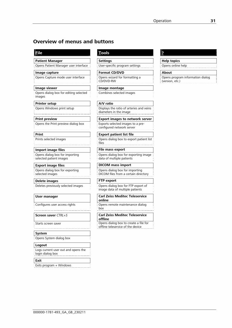
Overview of menus and buttons
File Tools ?
Patient Manager Settings Help topics Opens Patient Manager user interface User-specific program settings Opens online help
Image capture Format CD/DVD About Opens Capture mode user interface Opens wizard for formatting a
CD/DVD-RW Opens program information dialog
(version, etc.)
Image viewer Image montage Opens dialog box for editing selected images
Combines selected images
Printer setup A/V ratio Opens Windows print setup Displays the ratio of arteries and veins
diameters in the image
Print preview Export images to network serverOpens the Print preview dialog box Exports selected images to a pre-
configured network server
Print Export patient list file Prints selected images Opens dialog box to export patient list
files
Import image files File mass export
Opens dialog box for importing selected patient images
Opens dialog box for exporting image data of multiple patients
Export image files DICOM mass import
Opens dialog box for exporting selected images
Opens dialog box for importing DICOM files from a certain directory
Delete images FTP export
Deletes previously selected images Opens dialog box for FTP export of image data of multiple patients
User manager Carl Zeiss Meditec Teleservice online
Configures user access rights Opens remote maintenance dialog box
Screen saver CTRL+S Carl Zeiss Meditec Teleservice offline
Starts screen saver Opens dialog box to create a file for offline teleservice of the device
System Opens System dialog box
Logout Logs current user out and opens the login dialog box
Exit Exits program + Windows

Operation
000000-1781-493_GA_GB_230211
32
The Patient Manager and Capture mode user interfaces can also be operated using the program buttons. The table below gives an overview of the available buttons and their functions.
Click on the relevant button to activate the required function.
Icon Function Explanations
Returns to the Patient Manager user interface
The current settings are saved when returning to this window
Switches to the Capture mode user interface
The patient must have been selected beforehand
Opens Image viewer dialog box
All selected images are displayed
Opens the Print preview window
All selected images are displayed
Prints the selected images Starts printout without print preview
Opens dialog box for importing external images
Import is possible in the following graphic file formats: DICOM (*.dcm), JPEG (*.jpg), bitmap (*.bmp) and TIFF (*.tif).
Opens dialog box for exporting selected images
Export is possible in the following graphic file formats: DICOM (*.dcm), JPEG (*.jpg), bitmap (*.bmp) and TIFF (*.tif).
Deletes the selected images
Opens the Settings dialog box
Allows various settings to be configured
Opens the Online help window
Starts the image montage function
Select at least two images of an eye with the same capture mode.
Exports selected images to a pre-configured network server
Selected images are exported to a DICOM server or to an EMR system server (practice administration system) (depending on settings).
Starts the A/V ratio module After selecting a color image and clicking the A/V button the ratio of arteries and veins diameters is calculated and then displayed in the image.
Operation
000000-1781-493_GA_GB_230211
33
For further information on software operation please see the electronic software description in online help, accessible via menu item Help topics. In particular, the following warnings for activation of user management and use of the service and administrator password must be observed.
CAUTION - RISK OF OPERATING ERRORS
Activate the user administration (administrator rights required) in order to prevent access to the instrument and data by unauthorized persons. Assign the appropriate access rights to the persons authorized to use the instrument.
Ensure that the assigned passwords are protected from unauthorized access.
Configuration and network settings may only be changed by an experienced network administrator.
CAUTION - PROPERTY DAMAGE
A forgotten administrator password can only be recovered by Carl Zeiss Meditec Service!

Shutting down
000000-1781-493_GA_GB_230211
34
pÜìííáåÖ=Ççïå=
Switching off the instrument
WARNING - GENERAL HAZARDS
If one of the following events should occur, switch the instrument off immediately at the power switch, disconnect the cable from the power supply, label the instrument clearly as being out of service and report the problem to the Carl Zeiss Meditec service:
• Defective sensor for right/left detection (right/left detection in the image may be incorrect)
• Electric shock
• Penetration of substances
• Faults that cannot be remedied according to the descriptions in this user manual
To exit the software, select the Exit submenu from the File menu. This will bring up the Automatic functions before shut down (11Fig. 14).
Fig. 14 Automatic functions before shut down dialog box
Shutting down
000000-1781-493_GA_GB_230211
35
• In section 1. Automatic export function you can specify whether the day’s images are to be exported for data back-up, and whether a sub-folder is to be designated with the standard file name or date.
• In section 2. Automatic delete function you can specify which images are to be deleted.
Activate the relevant checkbox. If the Delete all images older than... option is selected, the date required can be entered via the keyboard (click on drop-down menu) or selected on the calendar (click on the arrow beside the drop-down menu).
If none these options are selected, no images will be deleted.
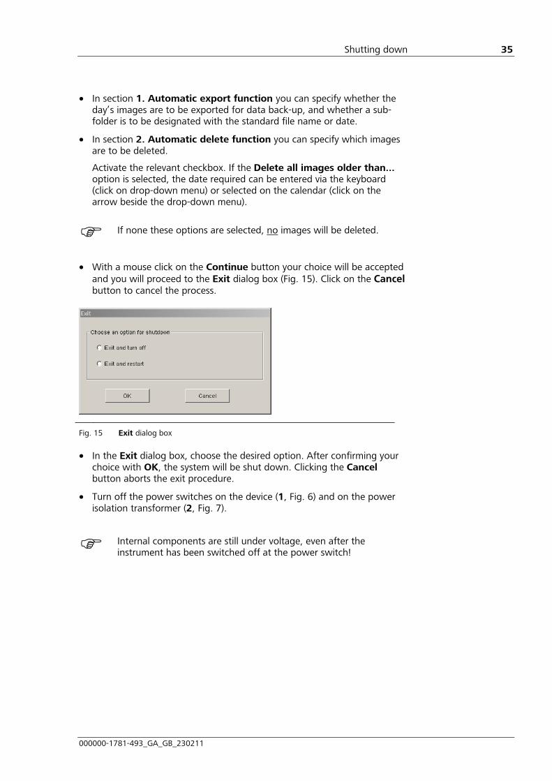
• With a mouse click on the Continue button your choice will be accepted and you will proceed to the Exit dialog box (11Fig. 15). Click on the Cancel button to cancel the process.
Fig. 15 Exit dialog box
• In the Exit dialog box, choose the desired option. After confirming your choice with OK, the system will be shut down. Clicking the Cancel button aborts the exit procedure.
• Turn off the power switches on the device (1, 11Fig. 6) and on the power isolation transformer (2, 11Fig. 7).
Internal components are still under voltage, even after the instrument has been switched off at the power switch!
Notes on angiography
000000-1781-493_GA_GB_230211
36
kçíÉë=çå=~åÖáçÖê~éÜó=
CAUTION - HAZARDS DUE TO SIDE EFFECTS
The contraindications and side effects of dye injections for angiography should be strictly observed to prevent any serious incidents. Please also follow the instructions of the manufacturer of the dye used for angiography.
Angiography using the VISUCAM 500
In FA/ICGA capture mode, monochrome images of a patient's eye are generated. For this purpose, the patient's eye is illuminated with light in different wavelengths which stimulates the injected solution (fluorescein-sodium (F) or indocyanine green (ICG)) to fluoresce. The emitted light (green) is filtered out in the camera beam path.
Image capture is triggered by pressing the release button on the joystick (8, 11Fig. 3).
Angiography is a diagnostic procedure conducted over a longer period. It is therefore documented with a series of images, i.e. each exposure is assigned to a particular FA running time.

Maintenance and care
000000-1781-493_GA_GB_230211
37
j~áåíÉå~åÅÉ=~åÇ=Å~êÉ==
WARNING - GENERAL HAZARDS
Further maintenance and care procedures above and beyond those specified in this section (maintenance, safety inspections and repairs) may only be carried out by persons authorized by Carl Zeiss Meditec and solely according to the service instructions issued by Carl Zeiss Meditec. For planning and implementing these maintenance and care procedures please contact Carl Zeiss Meditec customer service or your local dealer.
Fault remedy
Fault Possible cause Remedy
Power switch not switched on Switch power switch to ON No electric function
Basic unit power cable not connected
Connect cable to power supply
No image on monitor Monitor power cable not connected Connect cable to power supply
Monitor displays message "Cable not connected"
Monitor signal cable not connected to basic unit
Connect monitor signal cable to basic unit
No observation light Rotary knob for brightness control adjusted to minimum
Turn knob clockwise until light is adequate
Observation brightness is not continuously adjustable
Brightness control is defective Contact service department
Fixation lamp is dark Blinking diode defective Replace blinking diode as described in section 11Replacing the blinking diode of the fixation lamp on page 1138
Image is too dark, despite high light level
Flash bulb defective Contact service department

Maintenance and care
000000-1781-493_GA_GB_230211
38
Replacing the blinking diode of the fixation lamp
1 Blinking diode
2 Blinking diode holder
Fig. 16 Replacing the blinking diode
Unscrew the defective blinking diode (1, 11Fig. 16) from the holder (2, 11Fig. 16) and replace it with a new diode.

Maintenance and care
000000-1781-493_GA_GB_230211
39
Replacing the fuses
Only the fuses on the mains inputs (1, 11Fig. 7) of the power isolation transformer and basic unit (7, 11Fig. 6) may be replaced by the user.
Only use fuses specified in section 11Technical data (see page 1154).
Replacing the power isolation transformer fuse
1 Cover 2 Fuse 3 Fuse carrier 4 Snap-in clip
Fig. 17 Replacing the power isolation transformer fuse
• Open the cover (1, 11Fig. 17) located beneath the power connector.
• Remove the fuse carrier (3, 11Fig. 17) with fuse by pressing gently on the snap-in clip (4, 11Fig. 17) on the inside of the fuse carrier.
• Replace the defective fuse (2, 11Fig. 17) and reinsert the fuse carrier with fuse. Ensure that the fuse carrier snap-in clip is correctly positioned. The carrier must click into place.
• Close the cover.

Maintenance and care
000000-1781-493_GA_GB_230211
40
Replacing the basic unit fuse
1 Fuse compartment 2 Fuse 3 Fuse carrier
Fig. 18 Replacing the fuse at the basic unit
• Remove the fuse carrier (3, 11Fig. 18) with fuse by pressing gently on the snap-in clip.
• Replace the defective fuse (2, 11Fig. 18) and reinsert the fuse carrier with fuse. Ensure that the fuse carrier snap-in clip is correctly positioned.

Maintenance and care
000000-1781-493_GA_GB_230211
41
Maintenance
Operating the online remote maintenance module
The VISUCAM digital fundus camera is equipped with an online remote maintenance module, which enables you to contact Carl Zeiss Meditec Service for troubleshooting and remedy via the Internet.
The online remote maintenance module offers two problem resolution options:
• The VISUCAM user interface is made visible to a service technician. The operator carries out actions himself under instruction from the service technician.
• The user interface is visible to a service technician, who is able to operate or configure the VISUCAM directly using the remote control function.
To start remote maintenance, proceed as follows:
• Select Carl Zeiss Meditec Teleservice Online from the Tools menu. A dialog box will be displayed asking you to confirm the terms and conditions.
Fig. 19 Dialog box for confirmation of the conditions of use
• If you do not accept the conditions of use, terminate the procedure.
• If you accept the conditions of use, select Yes, I agree and click on OK. The remote maintenance login dialog box will be displayed.

Maintenance and care
000000-1781-493_GA_GB_230211
42
• Call the service team, who will provide you with a 6-digit session number.
• Enter the session number in the Session number field and click on OK.
• A connection will be established and the remote maintenance module control window will be displayed on your screen. The service team is now able to view the user interface of your instrument and resolve the problem by telephone.
• If it is necessary to activate the remote control function, click on the on button in the Remote control panel.
• Closing the control window will terminate the remote maintenance session.
Operating the offline remote maintenance module
If the VISUCAM Digital Fundus Camera does not have a network connection, the offline remote maintenance module can be used.
In the event of problems, the user can create an archive with information and screenshots of the occurring problem, export them to an external network drive or USB flash drive and send them by e-mail to Carl Zeiss Meditec Service.
Fig. 20 Dialog box for generating an archive for offline remote maintenance
To start offline remote maintenance, proceed as follows:
• A dialog box opens. Enter a description of the problem in the Problem description text box.
• Screenshots which serve to illustrate the problem may be added by pressing the Create screenshot button.
• If you consent to the image export, click on Yes in the following dialog box.

Maintenance and care
000000-1781-493_GA_GB_230211
43
Fig. 21 Request for consent to export a screenshot.
• In the next window specify the quality of the exported image.
• Once you have created all the necessary screenshots, click on Continue in the offline remote maintenance dialog box (see 11Fig. 20).
• In the next step select the external drive (network drive or USB flash drive) to which the archive is to be exported and click on Continue.
• If the creation of the archive was successful, a confirmation will be displayed. The file ServicePackage.svp will now be found on the drive specified in the last step. Send this file via e-mail to Carl Zeiss Meditec Service. Carl Zeiss Meditec Service will evaluate the file and issue instructions to solve the problem or arrange a service appointment with you.

Maintenance and care
000000-1781-493_GA_GB_230211
44
Care and cleaning
WARNING - RISK OF ELECTRIC SHOCK
Prevent moisture from penetrating the instrument or keyboard. Disconnect the power cable from the power supply before cleaning or disinfecting the instrument.
CAUTION - RISK DUE TO CROSS-CONTAMINATION
Parts with which the patient has come into contact during the examination (chin rest, forehead support) should be cleaned with a disinfectant approved for the purpose. These parts are resistant to wiping off with cleaning agents categorized as “low" (e.g. suds, quaternary ammonium compounds) and “intermediate” (e.g. alcohol, Javel water, iodine); classification pursuant to: Disinfectants and activity spectrum according to the Center for Disease Control and Prevention, Atlanta, USA.
CAUTION - RISK OF FALSE DIAGNOSIS
Use the supplied cover to protect the device against dust when not in use.
CAUTION - PROPERTY DAMAGE
The national disinfecting regulations must be observed in the choice of disinfectants and methods. Please note that some cleaning agents and disinfectants may have an adverse effect on plastic components. Damage caused by such disinfectants is not covered by our warranty. The surfaces of the instrument have been tested and are guaranteed to resist frequent treatment with alcoholic disinfectants and cleaning agents in the long term.
Never use aggressive or abrasive cleaning agents.
General
Heavily soiled painted surfaces should be cleaned with a cloth moistened with a weak soap solution.
To clean the printer, please also observe the information given in the manufacturer’s operating instructions.
When cleaning the monitor, use only denatured alcohol or commercially available cleaning cloths. Use commercially available cleaning cloths for the mouse and keyboard.
Use spray or wipe disinfectants for cleaning and disinfecting the instrument casing, chinrest and forehead strap.

Maintenance and care
000000-1781-493_GA_GB_230211
45
Replacing the paper pads
• Remove the two pins for fastening the paper pads (6, 11Fig. 4) on the head rest.
• Place the paper pads on the chin rest (5, 11Fig. 4) of the head rest.
• Re-insert the two holding pins through the holes in the paper pads and into the holes provided in the head rest.
• Tear off the top paper liner after each treatment.
Cleaning the front lens
The cleanliness of the front lens has a crucial influence on the quality of the captured images. Please ensure that the front lens is protected at all times from contamination due to skin contact, body fluids and dust. Use the protective cover supplied for the purpose.
Observe the following instructions when using the VISUCAM and for cleaning the front lens:
• Pull the VISUCAM towards the operator when not in use and lock it to ensure the greatest possible clearance between patient and instrument.
• Do not remove the protective cover from the lens until all preparations for capturing images have been completed.
• Never remove the lens from its casing for cleaning.
• Use cleaning utensils only once according to the instructions. If the result is not satisfactory, please use a new surface or cleaning set.
Use the following utensils for cleaning the front lens:
• Volk LensPen® cleaning pen � (available from optical retailers or directly supplied by Carl Zeiss Meditec, 000000-0483-896)
• Optical cleaning set (Carl Zeiss 000000-1216-071) or � cotton ball sticks or Safebuds from AF International (Order No. SBU000, http://www.af-net.com/docs/049contact.html)

Maintenance and care
000000-1781-493_GA_GB_230211
46
Frequent causes of lens contamination
• The main cause of simple and uncritical lens contamination is airborne dirt particles (e.g. dust).
• More serious contamination is caused by small drops of the patient’s tear fluid sprayed on the front lens when blinking.
• It is important to avoid serious contamination caused by the patient sneezing or touching the lens surface with the finger or nose. Fatty residue of this kind results in distinct bright areas on the image and can only be removed by moist cleaning.
Dust removal
• Dust or other loose particles on the lens surface can be quickly be removed with the LensPen (brush side) or the brush provided in the cleaning set.
• If necessary, the entire surface may be wiped with the special felt of the LensPen. For this purpose, apply gentle pressure to the entire lens surface with circular movements. Start in the center of the lens surface and wipe in circles outwards towards the edge.
Please note that upon replacement after cleaning or repeat wiping, the protective cap of the special felt tip must be rotated once.
Fig. 22 Remove dust from front lens
Removing splashes of tear fluid
Tear fluid drops are usually discernible in the images as light spots.
• Apply circular movements with the LensPen as described above.

Maintenance and care
000000-1781-493_GA_GB_230211
47
• If the desired result is still not achieved after repeated wiping, e.g. the bright spots remain visible, the lens surface must be moist cleaned (see 11Removing severe dirt accumulation).
Removing severe dirt accumulation
A typical reason for severe contamination is accidental contact between the front lens and the patient’s nose when the instrument was not positioned far enough away from the patient.
• Use the cleaning fluid and microfiber cloth or the moist disposable cloths provided in the cleaning set, cotton ball sticks or Safebuds.
• If a microfiber cloth is used, spray a small amount of cleaning fluid onto the tightly folded cloth and shake off any surplus fluid.
Never allow your fingers to touch the part of the utensil used for cleaning.
Hold the cloth between your fingers so they cannot touch the surface of the lens.
Preparing for cleaning with the Cleaning by circular movements folded cleaning cloth
Fig. 23 Cleaning with cleaning cloth
• Similar to the LensPen, start in the centre and make circular movements over the lens surface.
• Repeat this procedure several times, each time with a clean side of the cloth.
• Check the result by breathing on the lens and inspecting it for smudges and streaks.
• For fine cleaning, apply the cleaning disc of the LensPen as described above.

Maintenance and care
000000-1781-493_GA_GB_230211
48
Checking on the progress of cleaning In the absence of a patient, instant information on cleaning progress can be obtained by taking a photograph in the darkened room.
Before doing this, with the focusing aid switched on, turn the focusing knob until the displayed focusing bar extends to the left edge.
Besides the typical spatial structures, no significant bright spots should be visible in the resulting flash image. The pictures below (11Fig. 24) show examples of the image center (brighter due to post-treatment).
Contamination due to a fingerprint
Cleaning not yet optimal
Acceptable result
Fig. 24 Progress of cleaning
The following pictures (11Fig. 25) represent how contamination will appear in patient images.
The extremely bright spot was caused by contact with the finger or nose.
An image following moist cleaning. Fine cleaning with the LensPen also removes the residual light patches.
Fig. 25 Example for dirt and cleaning

Maintenance and care
000000-1781-493_GA_GB_230211
49
Data backup
Storing your image data on the hard disk is no substitute for archiving. We strongly recommend exporting image data daily for backup purposes.
The device’s software can be used to export medical and administrative data. The transfer of exported data via networks or the import of such data into third party application software may result in the loss of or unintended modification of medical information or unintended disclosure of confidential data. The manufacturer accepts no liability for the correct transfer and import of data and will not pay compensation for any damage incurred by such disruption.
No attempt should be made to tamper with the operating system! In particular, deactivation of the Windows firewall is not permitted!
The user should ensure that, where external data communication takes place, the system is protected from viruses.
Safety inspections
WARNING - RISK OF ELECTRIC SHOCK
The user is required to have the device inspected for safety once a year. Safety inspections may only be carried out by persons authorized by Carl Zeiss Meditec and solely according to the service instructions issued by Carl Zeiss Meditec. For planning and implementing these safety inspections please contact Carl Zeiss Meditec customer service or your local dealer.

Optional accessories
000000-1781-493_GA_GB_230211
50
léíáçå~ä=~ÅÅÉëëçêáÉë=
WARNING - RISK OF OPTICAL RADIATION
Use only accessories and spare parts approved by Carl Zeiss Meditec.
• Instrument table
• Monitor bracket
• Demonstration eye
• USB flash drive
• Stereo viewer
• Printer
A complete up-to-date list of accessories can be obtained from your dealer.
Mounting the monitor holder on an instrument table
CAUTION - DANGER FROM FALLING PARTS
Use only monitors up to a maximum weight of 7.5 kg.
Observe the instructions of the instrument table manufacturer and position the monitor holder at a sufficient distance from the table edge.
A drill hole with a diameter of 9 mm (1, 11Fig. 26) has been provided for the monitor holder at the rear of the instrument table (to the right of physician). If necessary, the table top (2, 11Fig. 26) may be drilled as desired.
• Position the retaining bracket of the monitor holder (4, 11Fig. 26) on the corresponding drill hole from above and secure the rod from below with a screw and a washer (3, 11Fig. 26).
• Secure the monitor with four screws and washers on the retaining plate of the monitor holder.
The required screws and tools are included with the monitor holder.
Instructions for dismantling the monitor foot are to be found in the monitor user manual.

Optional accessories
000000-1781-493_GA_GB_230211
51
1 Drill hole (9 mm diameter)
2 Tabletop
3 Screw
4 Retaining bracket
Fig. 26 Mounting the monitor holder
Demonstration eye
A demonstration eye for practicing operation of the VISUCAM can be supplied.
When required, the holder with the demonstration eye is inserted into the fastening pin holes for the paper pads (6, 12Fig. 4) on the head rest. By moving the unit longitudinally, an ametropia of ±5 D can be adjusted.
USB flash drive
The USB flash drive can be used for fast data transfer. It is connected to a vacant USB port on the VISUCAM connection panel.
CAUTION - PROPERTY DAMAGE
The USB flash drive should not be inserted or removed while the system is starting up or shutting down. It should not be removed from the system, when the LED on the USB flash drive is lit.

Optional accessories
000000-1781-493_GA_GB_230211
52
Stereo viewer
The stereo viewer can be used to view stereo images.
• Display a stereo image pair on the monitor.
• Hold the stereo viewer in front of your eyes, at a distance of 40 to 50 cm from the monitor.
• To obtain an optimum stereo impression adjust the lens system of the stereo viewer as per the enclosed manufacturer's information.
Printer
The printer is used for printing capture images. It is connected via the network (network printer), as described in the following.
Installation of a network printer
The VISUCAM supports PostScript® printers that can be connected via the Ethernet or a printer server. A network-capable PostScript® printer can be connected to the VISUCAM directly (peer to peer) or via an existing network.
Keep the user manual for your printer or printer server at hand. The printer must be configured according to the instructions contained in the user manual for the printer or printer server.
Peer-to-peer connection of printer with VISUCAM
• Connect the network printer or printer server to the VISUCAM using a so-called crossover cable or a non-crossover cable with a crossover adapter.
• Switch on the VISUCAM and printer or printer server.
• Configure the network printer or printer server with the aid of the user manual provided with the instrument as follows: IP address: 192.168.100.6 Subnet mask: 255.255.255.0

Optional accessories
000000-1781-493_GA_GB_230211
53
Connection of printer via an existing network
The administrator responsible for your local network must first of all set up a network printer or printer server in the network. The procedure for printer configuration is described in the user manual for the network printer or printer server. The IP address and subnet mask to be used will be assigned by the administrator of the network.
• Connect the VISUCAM to the network with a network cable.
• Switch on the VISUCAM and printer or printer server.
• On the File - System tab (see Software description of the VISUCAM) open the printer directory of Microsoft Windows using the Printer button.
A password is required to open the System dialog box (this can be obtained by contacting the Carl Zeiss Meditec Service).
• Click the right mouse button on Network Printer and select Properties.
• Select the Ports tab.
• Click on the Configure port... button and enter the IP address or network name of the network printer assigned by the responsible administrator in the Printer Name or IP Address box.
• Close the dialog with OK and then Close.
By default the VISUCAM is pre-configured to the static network address 192.168.100.1.

Technical data
000000-1781-493_GA_GB_230211
54
qÉÅÜåáÅ~ä=Ç~í~=
Rated voltage; frequency
Basic unit 100 V to 240 V AC (±10 %); 50/60 Hz
Power isolation transformer 100 V to 127 V AC (±10 %); 50/60 Hz or 220 V to 240 V AC (±10 %); 50/60 Hz
Power consumption
Basic unit max. 340 VA
Display max. 60 VA
Power isolation transformer max. 115 VA (total power consumption of connected external devices)
Protection mode IP 20 (conforming to EN 60529)
Protection class I (in accordance with EN 60601)
Use class (device type) B (in accordance with EN 60601-1)
IR LEDs Compliance with the requirements of Class 1 for light-emitting diodes pursuant to DIN EN 60825:2003 for wavelengths 830nm and 880 nm (output power < 1 mW)
Basic unit fuses 2 x T3.15 A H 250 V 5x20 IEC 60127
Power isolation transformer fuses 2 x T3.15 A H 250 V 5x20 IEC 60127 for 100 to 127 V AC 2 x T1.6 A H 250 V 5x20 IEC 60127 for 220 to 240 V AC
Battery of the PC motherboard
Type CR 2032
Manufacturer Varta
Ambient conditions for intended use
Temperature +10 °C to +35 °C
Rel. humidity 30 % to 90 %
Altitude up to 3,000 m above sea level
Ambient conditions for storage
Temperature -10 °C to +55 °C
Rel. humidity 10 % to 95 %
Ambient conditions for storage and transport in original packaging
Temperature -40 °C to +70 °C
Rel. humidity 10 % to 100 %

Technical data
000000-1781-493_GA_GB_230211
55
Dimensions
Basic unit 410 mm x 480 mm x 650 mm (head rest)
Display 400 mm x 400 mm x 100 mm
Weight
Basic unit 30 kg
Display 6 kg
Image capture
Field angle 45° and 30°
Ametropia compensation +35 D to -35 D continuous
Filter FA and ICGA filter set, filter for green and blue images as well as fundus autofluorescence, IR and Blue/IR cut filter (UV and IR protection)
Max. image sequence one image every 1.5 s - 2.0 s dependent on flash energy
Magnification 0.5x on image sensor (image diameter on sensor 7.4 mm), independent of focusing state

Electromagnetic compatibility
000000-1781-493_GA_GB_230211
56
bäÉÅíêçã~ÖåÉíáÅ=Åçãé~íáÄáäáíó=
Guidance and manufacturer’s declaration - electromagnetic emissions
The VISUCAM is intended for use in the electromagnetic environment specified below. The user of the VISUCAM should ensure that the device is used in such an environment
Emissions test Compliance Electromagnetic environment - guidance
RF emissions CISPR 11 Group 1 The VISUCAM uses RF energy only for its internal functions. Its RF emissions are therefore very low and not likely to cause any interference in nearby electronic equipment.
RF emissions CISPR 11 Class B
Harmonic emissions IEC 61000-3-2 Not applicable
Voltage fluctuations/flicker Not applicable
The VISUCAM is suitable for use in all establishments, including domestic establishments and those directly connected to the public low-voltage power supply network that supplies buildings used for domestic purposes.

Electromagnetic compatibility
000000-1781-493_GA_GB_230211
57
Guidance and manufacturer’s declaration - electromagnetic immunity
The VISUCAM is intended for use in the electromagnetic environment specified below. The user of the VISUCAM should ensure that the device is used in such an environment.
Immunity test IEC 60601-1-2 test level
Compliance level Electromagnetic environment - guidance
Electrostatic discharge (ESD) IEC 61000-4-2
±6 kV contact
±8 kV air
±6 kV contact
±8 kV air
Floors should be wood, concrete or ceramic tiles. If floors are covered with synthetic material, the relative humidity should be at least 30%.
Fast electrical transient/burst IEC 61000-4-4
±2 kV for power supply lines
±1 kV for input/output lines
±2 kV for power supply lines
±1 kV for input/output lines
Mains power quality should be that of typical commercial or hospital environments.
Surge IEC 61000-4-5 ±1 kV line(s) to line(s) ±2 kV line(s) to ground
±1 kV line(s) to line(s) ±2 kV line(s) to ground
Mains power quality should be that of typical commercial or hospital environments.
Voltage dips, short interruptions and voltage variations on power supply input lines IEC 61000-4-11
< 5 % UT (> 95 % dip in UT) for 0.5 cycle
40 % UT (60 % dip in UT) for 5 cycles
70 % UT (30 % dip in UT) for 25 cycles
< 5 % UT (> 95 % dip in UT) for 5 s
< 5 % UT (> 95 % dip in UT) for 0.5 cycle
40 % UT (60 % dip in UT) for 5 cycles
70 % UT (30 % dip in UT) for 25 cycles
< 5 % UT (> 95 % dip in UT) for 5 s
Mains power quality should be that of typical commercial or hospital environments. If the user of the VISUCAM requires continued operation during power mains interruptions, it is recommended that the VISUCAM be powered from an uninterruptible power supply.
Note: UT is the AC mains voltage prior to application of the test level.

Electromagnetic compatibility
000000-1781-493_GA_GB_230211
58
Guidance and manufacturer’s declaration - electromagnetic immunity
The VISUCAM is intended for use in the electromagnetic environment specified below. The user of the VISUCAM should ensure that the device is used in such an environment.
Immunity test IEC 60601-1-2 test level
Compliance level Electromagnetic environment - guidance
Conducted RF IEC 61000-4-6
3 Vrms 150 kHz to 80 MHz
3 V Portable and mobile RF communications equipment should be used no closer to any part of the VISUCAM, including cables, than the recommended separation distance calculated from the equation applicable to the frequency of the transmitter.
Recommended separation distance
d = 1.2 P
RF emissions IEC 61000-4-3
3 V/m 80 MHz to 2.5 GHz
3 V/m d = 1.2 P 80 MHz to 800 MHz
d = 2.3 P 800 MHz to 2.5 GHz
where P is the maximum nominal power of the transmitter in watts (W) stated by the manufacturer and d is the recommended separation distance in meters (m).
Field strengths from fixed RF transmitters1 should be less than the compliance level2 in each frequency range.
Interference may occur in the vicinity of equipment marked with the following symbol:
Note 1: At 80 MHz and 800 MHz the higher frequency range applies.
Note 2: These guidelines may not apply in all situations. Electromagnetic propagation is affected by absorption and reflection from structures, objects and people.
1 Field strengths from fixed transmitters, such as base stations for radio (cellular/cordless) and land mobile radios, amateur
radio and AM and FM radio broadcasting, cannot be predicted theoretically with accuracy. To assess the electromagnetic environment influenced by fixed RF transmitters, an electromagnetic site survey should be considered. If the measured field strength in the location in which the VISUCAM is used exceeds the applicable RF compliance level above, the
VISUCAM should be observed to verify normal operation. If abnormal performance is observed, additional measures may be necessary, e.g. re-orientating or relocating the VISUCAM.
2 Over the frequency range 150 kHz to 80 MHz, field strengths should be less than 3 V/m.

Electromagnetic compatibility
000000-1781-493_GA_GB_230211
59
Recommended separation distances between portable and mobile RF communications equipment and the VISUCAM
The VISUCAM is intended for use in an electromagnetic environment in which radiated RF disturbances are controlled. The user of the VISUCAM can help prevent electromagnetic interference by maintaining a minimum distance between portable and mobile RF communications equipment (transmitters) and the VISUCAM as recommended below, according to the maximum output power of the communications equipment.
Separation distance according to transmitter frequency
d [m]
150 kHz to 80 MHz 80 MHz to 800 MHz 800 MHz to 2.5 GHz
Maximum nominal output of the transmitter
P [W] d = 1.2 P d = 1.2 P d = 2.3 P
0.01 0.12 0.12 0.23
0.1 0.37 0.37 0.74
1 1.2 1.2 2.3
10 3.7 3.7 7.4
100 12 12 23
For transmission devices with nominal outputs not specified above, the recommended separation distance d in meters (m) can be estimated using an equation related to the frequency of the transmitter, in which P is the maximum nominal output of the transmitter in Watts (W) as stated by the manufacturer.
Note 1: At 80 and 800 MHz the higher frequency range applies.
Note 2: These guidelines may not apply in all situations. Electromagnetic propagation is affected by absorption and reflection from structures, objects and persons.

Abbreviations/Glossary
000000-1781-493_GA_GB_230211
60
^ÄÄêÉîá~íáçåëLdäçëë~êó=
AutoFluo Autofluorescence(capture mode)
B Blue (capture mode)
DICOM Digital Imaging and Communications in Medicine (Open standard for the exchange of digital images and corresponding patient data in the medical sector)
DIN Deutsches Institut für Normung (German standards institution)
D Diopter (unit of measurement for refractive power)
DVI Digital visual interface (interface for the digital transfer of video data)
EMR system Electronical medical record (practice management system)
EN European standard
FA Fluorescein angiography (capture mode)
Fig. Figure
FTP File transfer protocol (network protocol for data transfer)
G Green (capture mode)
ICGA Indocyanine green angiography (capture mode)
IEC International electrotechnical commission
IR Infrared
LED Light emitting diode
Network Broker Brokering service for communication with a DICOM server
PC Personal computer
R Red (capture mode)
USB Universal serial bus (standard interface for PC peripherals)
UV Ultraviolet
VGA Video graphics array (video signal output standard for PC)

Figures/Tables
000000-1781-493_GA_GB_230211
61
cáÖìêÉëLq~ÄäÉë=
Fig. 1 Labeling of VISUCAM ..................................................................10 Fig. 2 Basic instrument design...............................................................14 Fig. 3 VISUCAM controls, right hand view.............................................15 Fig. 4 VISUCAM controls, left hand view ...............................................16 Fig. 5 Transport of VISUCAM ................................................................18 Fig. 6 Connection panel of the VISUCAM ..............................................20 Fig. 7 Power isolation transformer, 120 V or 240 V, front view .............21 Fig. 8 Power isolation transformer, 240 V, rear view .............................21 Fig. 9 Power isolation transformer, 120 V, rear view .............................21 Fig. 10 Mounting the power isolation transformer ..................................22 Fig. 11 Control panel on instrument base................................................27 Fig. 12 Patient Manager user interface.................................................30 Fig. 13 Image capture user interface.....................................................30 Fig. 14 Automatic functions before shut down dialog box ................34 Fig. 15 Exit dialog box ...........................................................................35 Fig. 16 Replacing the blinking diode........................................................38 Fig. 17 Replacing the power isolation transformer fuse ...........................39 Fig. 18 Replacing the fuse at the basic unit .............................................40 Fig. 19 Dialog box for confirmation of the conditions of use ...................41 Fig. 20 Dialog box for generating an archive for offline remote
maintenance ...............................................................................42 Fig. 21 Request for consent to export a screenshot. ................................43 Fig. 22 Remove dust from front lens .......................................................46 Fig. 23 Cleaning with cleaning cloth .......................................................47 Fig. 24 Progress of cleaning ....................................................................48 Fig. 25 Example for dirt and cleaning ......................................................48 Fig. 26 Mounting the monitor holder ......................................................51

Index
000000-1781-493_GA_GB_230211
62
fåÇÉñ=
A
Abbreviations............................................................................................ 60 Accessories, optional ................................................................................ 50 Angiography............................................................................................. 36
B
Blinking diode, replacing........................................................................... 38
C
Care.......................................................................................................... 44 Cleaning ................................................................................................... 44 Control ..................................................................................................... 26 Control panel............................................................................................ 27
D
Daily use ................................................................................................... 23 Data backup ............................................................................................. 49 Demonstration eye.................................................................................... 51 Description of the device........................................................................... 14 Device classification .................................................................................... 6 DICOM ....................................................................................................... 6 Disposal ...................................................................................................... 9
E
Electrical connection ................................................................................. 19 Electromagnetic compatibility ................................................................... 56
F
Fault remedy............................................................................................. 37 Figures...................................................................................................... 61 Fluorescein angiography ........................................................................... 36 Functional description............................................................................... 12 Fuses ........................................................................................................ 39
G
Glossary.................................................................................................... 60
I
ICG Angiography ...................................................................................... 36 Indication for use........................................................................................ 7 Installation...........................................................................................17, 19
L
Labels ....................................................................................................... 10

Index
000000-1781-493_GA_GB_230211
63
M
Maintenance .............................................................................................41 Maintenance and care ...............................................................................37 Manufacturer’s declaration..........................................................................6 Menus.......................................................................................................31
O
Operation..................................................................................................25
P
Package check list........................................................................................5 Paper pads ................................................................................................45 Performance specifications ........................................................................12 Power isolation transformer.......................................................................21 Printer .......................................................................................................52 Printer installation .....................................................................................52
R
Remote maintenance.................................................................................41
S
Safety inspections......................................................................................49 Screen layout.............................................................................................29 Service life .................................................................................................13 Shortcuts...................................................................................................28 Shutting down ..........................................................................................34 Stereo viewer ............................................................................................52 Switch off..................................................................................................34 Switching on .......................................................................................20, 24 Symbols.......................................................................................................4
T
Tables........................................................................................................61 Technical data ...........................................................................................54 Teleservice.................................................................................................41
U
Unpacking.................................................................................................18 USB flash drive ..........................................................................................51 User interface
Capture mode........................................................................................29 Patient Manager ....................................................................................29
W
Window ....................................................................................................26

Carl Zeiss Meditec AG Goeschwitzer Str. 51-52 07745 Jena Germany
Phone: +49 3641 220 333 Fax: +49 3641 220 112 Email: [email protected] Internet: www.meditec.zeiss.com
000000-1781-493_GA_GB_230211 VISUCAM
Specifications subject to change
000000-1781-493_Inhalt2_GB
`çåíÉåí=
Addendum to the document set Notes on the use of the optional MPD module
[000000-1781-493_AddGA01_GB_220710]
2

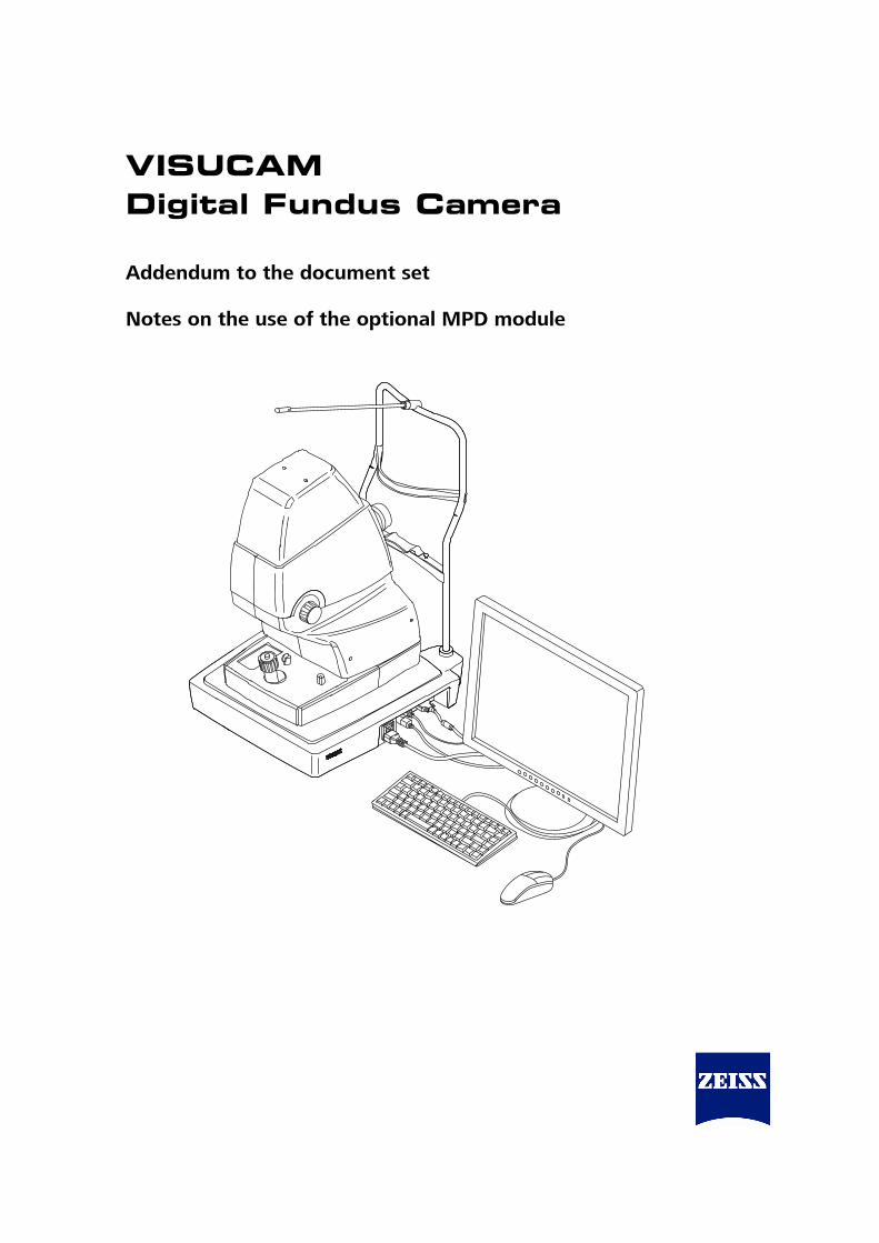
sfpr`^j=aáÖáí~ä=cìåÇìë=`~ãÉê~==Addendum to the document set Notes on the use of the optional MPD module

000000-1781-493_AddGA01_GB_220710
Addendum to the document set VISUCAM Digital Fundus Camera, MPD module 000000-1781-493_AddGA01_GB_220710 22.07.2010 © 2010, Carl Zeiss Meditec AG, Jena All rights reserved in the event of granting of patents or registration as a utility patent. All names of companies and products cited in this manual may be trademarks or registered trademarks. Third party products are cited for information purposes only. This does not represent approval or recommendation of these products. Carl Zeiss Meditec AG accepts no liability for the performance or use of such products. Other brand names, software and hardware names used in this user manual are generally subject to trademark or patent protection. The quoting of products is for informational purposes only and does not represent a trademark misuse. This user manual is protected by copyright. Unless expressly authorized in writing, dissemination, duplication or other commercial exploitation of this document or communication of its contents or parts of it is not permitted. In case of infringement, the violator may be liable to pay compensation for damages. Specifications due to technical developments are subject to change. This manual is not subject to the revision service. Please contact the manufacturer or authorized dealer to request the latest edition of the manual.
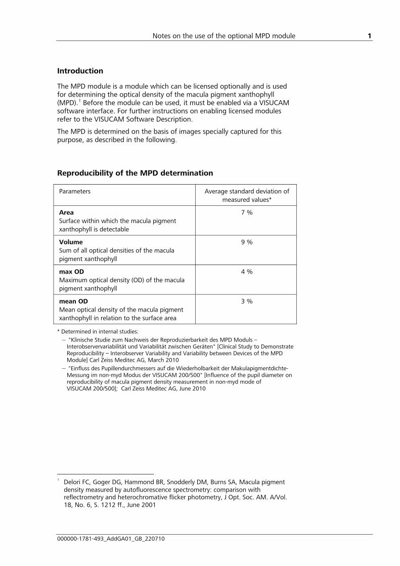
Notes on the use of the optional MPD module
000000-1781-493_AddGA01_GB_220710
1
Introduction
The MPD module is a module which can be licensed optionally and is used for determining the optical density of the macula pigment xanthophyll (MPD).1 Before the module can be used, it must be enabled via a VISUCAM software interface. For further instructions on enabling licensed modules refer to the VISUCAM Software Description.
The MPD is determined on the basis of images specially captured for this purpose, as described in the following. Reproducibility of the MPD determination
Parameters Average standard deviation of measured values*
Area Surface within which the macula pigment xanthophyll is detectable
7 %
Volume Sum of all optical densities of the macula pigment xanthophyll
9 %
max OD Maximum optical density (OD) of the macula pigment xanthophyll
4 %
mean OD Mean optical density of the macula pigment xanthophyll in relation to the surface area
3 %
* Determined in internal studies: – "Klinische Studie zum Nachweis der Reproduzierbarkeit des MPD Moduls –
Interobservervariabilität und Variabilität zwischen Geräten" [Clinical Study to Demonstrate Reproducibility – Interobserver Variability and Variability between Devices of the MPD Module] Carl Zeiss Meditec AG, March 2010
– "Einfluss des Pupillendurchmessers auf die Wiederholbarkeit der Makulapigmentdichte-Messung im non-myd Modus der VISUCAM 200/500" [Influence of the pupil diameter on reproducibility of macula pigment density measurement in non-myd mode of VISUCAM 200/500]; Carl Zeiss Meditec AG, June 2010
1 Delori FC, Goger DG, Hammond BR, Snodderly DM, Burns SA, Macula pigment
density measured by autofluorescence spectrometry: comparison with reflectrometry and heterochromative flicker photometry, J Opt. Soc. AM. A/Vol. 18, No. 6, S. 1212 ff., June 2001

Notes on the use of the optional MPD module
000000-1781-493_AddGA01_GB_220710
2
Capturing images for determining MPD
In the MPD capture mode all settings are already determined except Flash light level and Boost 1. The settings for Flash light level and Boost 1 will be imported from the most recent MPD image of the patient's eye (if existing).
Start image capture by pressing the MPD button (1, Fig. 1) in the Capture mode user interface.
1
2
1 MPD button
2 Drop-down menu for internal fixation aid mark positioning
Fig. 1 Capture mode user interface
The use of the boost mode (Boost 1) and flash light level 10 is recommended for images for determining the MPD. If the boost mode is not used, flash light level 12 is recommended. Higher flash-energy levels must be used for strongly pigmented retinas. The flash light may be increased by up to 3 levels.
When using an individual flash light level please note that in the center of the macula the fundus image displays low grey values. If the center is black, the flash light level must be increased.
The peripheral area around the macula should not be overexposed. Lower the flash light level if the peripheral area is overexposed.

Notes on the use of the optional MPD module
000000-1781-493_AddGA01_GB_220710
3
Please note that the MPD image in non-myd mode should always be the first fundus image for the patient on this day, to ensure that the pupil is sufficiently large. The pupil should be no more than 10% smaller than the inner yellow ring when the device is pulled back to its stop position by the operator.
Check that the patient's pupil is of sufficient size in the live viewer window prior to each image capture. If the pupil is too small it must be dilated with a mydriatic.
Continue with the camera alignment as described in the VISUCAM user manual.
The Central (2, Fig. 1) position should be selected for internal fixation. This will ensure that the macula is in the center of the image. Ask the patient to look at the internal fixation mark.
Any deviation from the standard (central fixation) will require the same fixation position for further images. For example, for progress monitoring the fixation position of the first image should always be selected.
Ensure that the patient is not wearing contact lenses, as this may influence the MPD value.
When taking images, care must also be taken to ensure that the front lens is clean (see Cleaning the front lens in the VISUCAM user manual).
Notes on progress monitoring
For progress monitoring of MPD values, image capture must either always be mydriatic or always non-mydriatic.
Please note that the size of the pupil may affect the calculated values.
When capturing images for MPD progress monitoring always ensure constant ambient lighting and flash-energy levels.
No data is available on the extent to which systematic diseases and eye ailments, e.g. glaucoma and diabetic retinopathy, or changeover of medication influence the determined MPD values.

Notes on the use of the optional MPD module
000000-1781-493_AddGA01_GB_220710
4
Determining the optical density of the macula pigment xanthophyll
Selecting MPD image
Select the respective patient, visit and MPD image (1, 2, 3, Fig. 2), as described in the VISUCAM Software description.
Only one image at a time can be selected for determining the MPD.
Launch MPD determination by clicking on the MPD (5, Fig. 2) icon in the Patient Manager user interface.
5
2
43
1
1 Selected patient
2 Selected visit
3 Selected MPD image
4 MPD image with analysis
5 Icon for launching the MPD module
Fig. 2 Patient Manager user interface with selected MPD image

Notes on the use of the optional MPD module
000000-1781-493_AddGA01_GB_220710
5
Selecting analysis data for the MPD Progression Chart
If the MPD for the same eye of this patient was determined from earlier sessions, the Selection for MPD Progression Chart dialog box (Fig. 3) will open. Here, all earlier analysis data are displayed for this patient's eye. By default all values for the graphic display in the MPD Progression Chart are selected.
Individual values may be de-selected by mouse-click to exclude them from the display. Confirm your selection by clicking on OK.
Fig. 3 Selection for MPD Progression Chart dialog box
The MPD module overview window will subsequently be displayed with the four windows MPD Progression Chart, MPD Fundus Image, 3D View and Report Comment (Fig. 4), with the aid of which the MPD can be determined and documented.
Correcting position of the fovea
The current MPD image is displayed in the MPD Fundus Image (1, Fig. 4) window.
The fovea is automatically determined and highlighted in the image. If necessary, the fovea position mark can be changed by clicking on the Mark Fovea (8, Fig. 4) button and then clicking the left mouse button on the desired new position of the fovea in the image. The correction will be saved by pressing the right mouse button.

Notes on the use of the optional MPD module
000000-1781-493_AddGA01_GB_220710
6
The window layout can be rearranged according to the screen format.
1
3 4
2
10
9
8
7
6
5
1 MPD Fundus Image window
2 3D view window
3 Report Comment window
4 MPD Progression Chart window
5 Close button
6 Create Report button
7 Analyze button
8 Mark Fovea button
9 Help button 10 IOL checkbox (should be activated if the patient eye being examined has an IOL)
Fig. 4 MPD module overview window

Notes on the use of the optional MPD module
000000-1781-493_AddGA01_GB_220710
7
MPD determination
Activate the IOL check box (10, Fig. 4) if the patient eye to be examined has an intraocular lens.
Click on the Analyze button (7, Fig. 4) to determine the optical density of the macula pigment xanthophyll. The result will be displayed via the examined surface of the image in false colour representation (1, Fig. 4). In addition the newly calculated values will be shown in the MPD Progression Chart (4, Fig. 4) and as three-dimensional display in the 3D-View (2, Fig. 4) window.
Editing the 3D view
After the analysis a three-dimensional display of the optical density of the macula pigment xanthophyll will appear over the analyzed surface in the 3D View window (2, Fig. 4).
The viewing angle can be changed by clicking the left mouse button on the display and moving the mouse. If the <Shift> button is simultaneously pressed, the viewing angle will remain constant but the display will be shifted horizontally or vertically according to the mouse movement.
The <Pos1> button activates the top view and the <End> button the profile view. Use <Scroll up> and <Scroll down> or the mouse scroll wheel to increase or reduce the size of the display.
The last 3D View will be used in the report and in the image saved in the database.
Displaying results in the MPD Progression Chart
If earlier analysis values have been selected for the graphic display in the Selection for MPD Progression Chart dialog box (Fig. 3), these will be shown in the MPD Progression Chart window (4, Fig. 4). After analysis the values from the current evaluation will be added.
The following values can be selected by mouse click to be displayed in the progression chart.
• Volume
• Area
• max OD
• mean OD

Notes on the use of the optional MPD module
000000-1781-493_AddGA01_GB_220710
8
Adding comments
Additional comments can be made in the Report Comment (3, Fig. 4) window. The comments will be included in the report.
Create or print report
The Create Report button (6, Fig. 4) can be used to create or print out a report in PDF format. The report contains all information displayed in the overview (Fig. 4) (time line display, MPD image, three-dimensional display and any additional comments entered).
Closing the MPD module overview window
Press Close (5, Fig. 4) to close the complete overview window. The analyzed image (4, Fig. 2) will be automatically saved in the database to the right of the respective MPD image.
The report in PDF format contains the analyzed MPD image in optimum print quality. Only a compressed JPG image will be stored in the database.

Notes on the use of the optional MPD module
000000-1781-493_AddGA01_GB_220710
9
Index
3
3D view.......................................................................................................7
A
Analysis .......................................................................................................7 Analysis data ...............................................................................................5
B
Boost 1 .......................................................................................................2
C
Comments...................................................................................................8
F
Flash light level ............................................................................................2 Fovea ..........................................................................................................5
I
Image capture .............................................................................................2
M
Macula pigment ..........................................................................................4 MPD determination .....................................................................................7 MPD Fundus Image .....................................................................................5 MPD module
Close .......................................................................................................8 Launch ....................................................................................................4 Overview window ................................................................................5, 6
MPD Progression Chart............................................................................5, 7
O
Optical density.............................................................................................4
P
Patient manager ..........................................................................................4 Progress monitoring ............................................................................3, 5, 7 Progression chart.........................................................................................5
R
Report .........................................................................................................8 Reproducibility.............................................................................................1
S
Selection for MPD Progression Chart ...........................................................5
X
Xanthophyll.................................................................................................4

Carl Zeiss Meditec AG Goeschwitzer Str. 51-52 07745 Jena Germany
Phone: +49 3641 220 333 Fax: +49 3641 220 112 Email: [email protected] Internet: www.meditec.zeiss.com
000000-1781-493_AddGA01_GB_220710 VISUCAM, MPD module
Specifications subject to change

000000-1781-493_Inhalt3_GB
`çåíÉåí=
Notes on and conditions of use for the remote maintenance tool
[000000-1305-000_AddGA01_GB_040610]
3


Notes on and conditions of use for the remote maintenance tool
000000-1305-000_AddGA01_GB_040610
1
1. Use of the remote maintenance tool requires that the Carl Zeiss Meditec AG service team or a company authorised by them be contacted beforehand.
2. The remote maintenance function can be activated by the user only. This requires the entry of an
activation code. The user can then switch between observation mode and remote control mode. The user can abort the selected remote maintenance mode at any time by closing the remote maintenance dialog box. It is not possible for the service technician to start or restart observation mode without the user's consent.
3. In observation mode, a service technician from Carl Zeiss Meditec AG or a company authorised by
them is able to continuously view a copy of the current program interface. Service personnel may therefore be able to view patient details if they are displayed in the visible program interface. It is entirely the responsibility of the user to take all necessary measures to ensure that confidential data is protected during the remote maintenance session and that all legal regulations are adhered to.
4. In remote control mode, a service technician from Carl Zeiss Meditec AG or an authorised company
is able to operate the instrument’s user interface with the privileges of the currently logged in user. Remote control mode can be terminated at any time by pressing "F5". The program will then switch to observation mode. It is solely the user’s responsibility to take all necessary measures to ensure that confidential data is protected during the remote maintenance session and that all legal regulations are adhered to.
5. The user may not leave the instrument unsupervised in observation or remote maintenance mode.
Under no circumstances is the remote maintenance tool to be used for fault diagnosis while treatment is being carried out. The user must alert the service technician from Carl Zeiss Meditec AG or a company authorised by them by telephone if there are other people in the room in which the instrument is located during a remote maintenance session.
6. The user is solely responsible for the safe operation of the instrument during a remote maintenance
session. 7. No guarantee is entered into for advice given during a remote maintenance session.
Carl Zeiss Meditec AG in particular does not guarantee that they or a company authorised by them will be able to diagnose or remedy a fault using remote maintenance mode. If it is not possible to diagnose or remedy the fault in remote maintenance mode, the user will need to request that a service technician attend the installation. This will incur further costs.
8. The user may only permit the use of remote maintenance mode if the currently logged on user’s
privileges do not permit unauthorised access to protected data. 9. The user may only permit the use of remote maintenance mode if no danger can arise to patients
or other persons through the operation of the instrument in remote maintenance mode.

Notes on and conditions of use for the remote maintenance tool
2
10. Except in cases of intent or gross negligence, Carl Zeiss Meditec AG accepts no liability - on any legal basis - for damages arising during fault diagnosis or maintenance in remote maintenance mode.
11. Place of jurisdiction is, for commercial customers, the registered place of business of the
Carl Zeiss Group company making use of these conditions of use. We are, however, also entitled to pursue claims against you at your official place of business.
12. The law of the Federal Republic of Germany applies, with the exclusion of UN sales law and the
referral provisions of German private international law. 13. In addition, the currently applicable version of the general terms and conditions for service
agreements apply to all remote maintenance procedures. Users can view the current version of the general terms and conditions for service agreements on the internet at http://www.meditec.zeiss.com/terms.
14. Should any individual provisions of these conditions be in part or in full invalid, the validity of the
remaining provisions or the remaining parts of such provisions shall not be affected.
Carl Zeiss Meditec AG Goeschwitzer Str. 51-52 07745 Jena Germany
Phone: +49 3641 220 333 Fax: +49 3641 220 112 Email: [email protected] Internet: www.meditec.zeiss.com
000000-1305-000_AddGA01_GB_040610 Remote maintenance tool
© Carl Zeiss Meditec AG, Jena Specifications subject to change

000000-1781-493_Inhalt4_GB
`çåíÉåí=
Microsoft Software License Terms
[LT_XP_PRO_embedded_080807]
4


LT_XP_PRO_embedded_080807 1
MICROSOFT SOFTWARE LICENSE TERMS FOR:
MICROSOFT® WINDOWS® 2000 PROFESSIONAL FOR EMBEDDED SYSTEMS (1-2 CPU VERSION) MICROSOFT® WINDOWS® XP PROFESSIONAL 64 BIT EDITION FOR EMBEDDED SYSTEMS (1-2 CPU) MICROSOFT® WINDOWS® XP PROFESSIONAL FOR EMBEDDED SYSTEMS (1-2 CPU VERSION) MICROSOFT® WINDOWS® XP PROFESSIONAL FOR EMBEDDED SYSTEMS – RUSSIAN VERSION (1-2 CPU VERSION) MICROSOFT® WINDOWS® XP PROFESSIONAL FOR EMBEDDED SYSTEMS – SIMPLIFIED CHINESE VERSION (1-2 CPU VERSION)
These license terms are an agreement between you and Carl Zeiss Meditec AG [CZM]. Please read them. They apply to the software included on this device. The software also includes any separate media on which you received the software.
The software on this device includes software licensed from Microsoft Corporation or its affiliate.
The terms also apply to any Microsoft
• updates,
• supplements,
• Internet-based services, and
• support services
for this software, unless other terms accompany those items. If so, those terms apply. If you obtain updates or supplements directly from Microsoft, then Microsoft, and not [CZM], licenses those to you.
As described below, using some features also operates as your consent to the transmission of certain standard computer information for Internet-based services.
By using the software, you accept these terms. If you do not accept them, do not use the software. Instead, contact [CZM] to determine its return policy for a refund or credit.
If you comply with these license terms, you have the rights below.
1. USE RIGHTS.
You may use the software on the device with which you acquired the software.
Processor Limit. You may use the software with no more than two (2) processors at any one time.
2. ADDITIONAL LICENSING REQUIREMENTS AND/OR USE RIGHTS.
a. Specific Use. [CZM] designed this device for a specific use. You may only use the software for that use.
b. Other Software. You may use other programs with the software as long as the other programs
• directly support the manufacturer’s specific use for the device, or
• provide system utilities, resource management, or anti-virus or similar protection.
Software that provides consumer or business tasks or processes may not run on the device. This includes email, word processing, spreadsheet, database, scheduling and personal finance software. The device may use terminal services protocols to access such software running on a server.
c. Device Connections. You may not use the software as server software. In other words, more than one device may not access, display, run, share or use the software at the same time. You may allow up to ten other devices to access the software to use
• File Services,
• Print Services,
• Internet Information Services, and
• Internet Connection Sharing and Telephony Services.

LT_XP_PRO_embedded_080807 2
The ten connection limit applies to devices that access the software indirectly through "multiplexing" or other software or hardware that pools connections. You may use unlimited inbound connections at any time via TCP/IP.
3. SCOPE OF LICENSE. The software is licensed, not sold. This agreement only gives you some rights to use the software. [CZM] and Microsoft reserve all other rights. Unless applicable law gives you more rights despite this limitation, you may use the software only as expressly permitted in this agreement. In doing so, you must comply with any technical limitations in the software that allow you to use it only in certain ways. For more information, see the software documentation or contact [CZM]. Except and only to the extent permitted by applicable law despite these limitations, you may not:
• work around any technical limitations in the software,
• reverse engineer, decompile or disassemble the software,
• make more copies of the software than specified in this agreement,
• publish the software for others to copy,
• rent, lease or lend the software, or
• use the software for commercial software hosting services.
Except as expressly provided in this agreement, rights to access the software on this device do not give you any right to implement Microsoft patents or other Microsoft intellectual property in software or devices that access this device.
• INTERNET-BASED SERVICES. Microsoft provides Internet-based services with the software. Microsoft may change or cancel them at any time.
a. Consent for Internet-Based Services. The software features described below connect to Microsoft or service provider computer systems over the Internet. In some cases, you will not receive a separate notice when they connect. You may switch off these features or not use them. For more information about these features, visit http://www.microsoft.com/windowsxp/downloads/updates/sp2/docs/privacy.mspx. By using these features, you consent to the transmission of this information. Microsoft does not use the information to identify or contact you.
b. Computer Information. The following feature uses Internet protocols, which send to the appropriate systems computer information, such as your Internet protocol address, the type of operating system, browser and name and version of the software you are using, and the language code of the device where you installed the software. Microsoft uses this information to make the Internet-based services available to you.
• Web Content Features. Features in the software can retrieve related content from Microsoft and provide it to you. To provide the content, these features send to Microsoft the type of operating system, name and version of the software you are using, type of browser and language code of the device where the software was installed. Examples of these features are clip art, templates, online training, online assistance and Appshelp. You may choose not to use these web content features.
• Windows Media Digital Rights Management. Content owners use Windows Media Digital Rights Management technology (WMDRM) to protect their intellectual property, including copyrights. This software and third party software use WMDRM to play and copy WMDRM-protected content. If the software fails to protect the content, content owners may ask Microsoft to revoke the software’s ability to use WMDRM to play or copy protected content. Revocation does not affect other content. When you download licenses for protected content, you agree that Microsoft may include a revocation list with the licenses. Content owners may require you to upgrade WMDRM to access their content. Microsoft software that includes WMDRM will ask for your consent prior to the upgrade. If you decline an upgrade, you will not be able to access content that requires the upgrade. You may switch off WMDRM features that access the Internet. When these features are off, you can still play content for which you have a valid license.
c. Misuse of Internet-based Services. You may not use these services in any way that could harm them or impair anyone else’s use of them. You may not use the services to try to gain unauthorized access to any service, data, account or network by any means.

LT_XP_PRO_embedded_080807 3
• NOTICES ABOUT THE MPEG-4 VISUAL STANDARD. The software may include MPEG-4 visual decoding technology. This technology is a format for data compression of video information. MPEG LA, L.L.C. requires this notice: USE OF THIS PRODUCT IN ANY MANNER THAT COMPLIES WITH THE MPEG-4 VISUAL STANDARD IS PROHIBITED, EXCEPT FOR USE DIRECTLY RELATED TO (A) DATA OR INFORMATION (i) GENERATED BY AND OBTAINED WITHOUT CHARGE FROM A CONSUMER NOT THEREBY ENGAGED IN A BUSINESS ENTERPRISE, AND (ii) FOR PERSONAL USE ONLY; AND (B) OTHER USES SPECIFICALLY AND SEPARATELY LICENSED BY MPEG LA, L.L.C. If you have questions about the MPEG-4 visual standard, please contact MPEG LA, L.L.C., 250 Steele Street, Suite 300, Denver, CO 80206; www.mpegla.com.
4. PRODUCT SUPPORT. Contact [CZM] for support options. Refer to the support number provided with the device.
5. BACKUP COPY. You may make one backup copy of the software. You may use it only to reinstall the software on the device.
6. PROOF OF LICENSE. If you acquired the software on the device, or on a disc or other media, a genuine Certificate of Authenticity label with a genuine copy of the software identifies licensed software. To be valid, this label must be affixed to the device, or included on or in [CZM]’s software packaging. If you receive the label separately, it is not valid. You should keep the label on the device or packaging to prove that you are licensed to use the software. To identify genuine Microsoft software, see http://www.howtotell.com.
7. TRANSFER TO A THIRD PARTY. You may transfer the software only with the device, the Certificate of Authenticity label, and these license terms directly to a third party. Before the transfer, that party must agree that these license terms apply to the transfer and use of the software. You may not retain any copies of the software including the backup copy.
8. NOT FAULT TOLERANT. The software is not fault tolerant. [CZM] installed the software on the device and is responsible for how it operates on the device.
9. RESTRICTED USE. The Microsoft software was designed for systems that do not require fail-safe performance. You may not use the Microsoft software in any device or system in which a malfunction of the software would result in foreseeable risk of injury or death to any person. This includes operation of nuclear facilities, aircraft navigation or communication systems and air traffic control.
10. NO WARRANTIES FOR THE SOFTWARE. The software is provided "as is". You bear all risks of using it. Microsoft gives no express warranties, guarantees or conditions. Any warranties you receive regarding the device or the software do not originate from, and are not binding on, Microsoft or its affiliates. When allowed by your local laws, [CZM] and Microsoft exclude implied warranties of merchantability, fitness for a particular purpose and non-infringement.
11. LIABILITY LIMITATIONS. You can recover from Microsoft and its affiliates only direct damages up to two hundred fifty U.S. Dollars (U.S. $250.00), or equivalent in local currency. You cannot recover any other damages, including consequential, lost profits, special, indirect or incidental damages.
This limitation applies to:
• anything related to the software, services, content (including code) on third party internet sites, or third party programs, and
• claims for breach of contract, breach of warranty, guarantee or condition, strict liability, negligence, or other tort to the extent permitted by applicable law.
It also applies even if Microsoft should have been aware of the possibility of the damages. The above limitation may not apply to you because your country may not allow the exclusion or limitation of incidental, consequential or other damages.
12. EXPORT RESTRICTIONS. The software is subject to United States export laws and regulations. You must comply with all domestic and international export laws and regulations that apply to the software. These laws include restrictions on destinations, end users and end use. For additional information, see www.microsoft.com/exporting.

Carl Zeiss Meditec AG Goeschwitzer Str. 51-52 07745 Jena Germany
Phone: +49 3641 220 333 Fax: +49 3641 220 112 Email: [email protected] Internet: www.meditec.zeiss.com
000000-1781-493_DokS_GB_070311 VISUCAM
Specifications subject to change