Visualization of Ground Target Designation from an ... imaging. Once the track has been designated,...
12
1 Presented at SPIE Aerosense, Radar Sensor Technology, Orlando, Fl April 16, 1998 Visualization of ground target designation from an unmanned aerial vehicle Deborah J. Violette Pierce John J. SantaPietro The MITRE Corporation ∗ ABSTRACT The Common Ground Station (CGS) receives data from the Joint Surveillance and Target Attack Radar System (Joint STARS) aircraft and from other airborne platforms. High-resolution imagery such as that provided by an unmanned airborne vehicle (UAV) carrying an infrared (IR) and/or synthetic aperture radar (SAR) sensor will be incorporated into an Advanced Imagery CGS (AI CGS) operation. While this level of integration provides a wealth of valuable information, it also increases the complexity of planning, assessment and exploitation which in turn dictates flexible simulation tools for mission rehearsal and operator training. MITRE has developed a ModSAF-driven model for a UAV equipped with a moving target indicator (MTI) radar for wide-area surveillance, and a Battlefield Combat Identification System (BCIS) for positive identification of friendly forces. The imaging functions are performed by integrating the UAV model with visualization software in order to render the sensor’s view in real-time. This model forms the basis for a multisensor CGS simulation (MSCGS) which consists of the multisensor UAV combined with a UAV Control Station (UAV CS). The UAV CS controls imaging task assignments which take place when an MTI track is selected for imaging by means of a mouse click entry on an active MTI display. At that time, the UAV is commanded to fly an automatically determined trajectory in order to align itself for the imaging task. A beam footprint whose position, size and shape is determined by the sensor position, attitude, and field-of-view appears on the display as an indication of the relationship of the image display to the terrain in the operational scenario. A three-dimensional visualization of the designated target area then takes place on a separate display. Keywords: MTI radar, target designation, modeling & simulation, sensor simulation, ground station 1. BACKGROUND The Advanced Imagery product improvement to the CGS (AI CGS) is capable of real-time imagery acquisition, management, exploitation and display. Such close-in high-resolution imagery is provided by an unmanned airborne vehicle (UAV) carrying an infrared (IR) and/or synthetic aperture radar (SAR) sensor. The increased complexity introduced by integrating target reports and imagery from multiple sensors requires expanded capabilities for planning and training tools. Recorded imagery cannot completely satisfy this requirement since it is specific to a particular operational scenario and ambient environment and cannot provide extensive insight into UAV mission planning or flight management. This requirement can only be completely satisfied by the capability to generate realistic synthetic imagery which accurately reflects the virtual environment within a simulated scenario. This imagery needs to be provided within the context of a general purpose simulation environment which accommodates a wide variety of battlespace scenarios. In order to achieve this goal, we have designed and demonstrated a prototype version of a simulated airborne surveillance platform entity (a UAV) carrying a multisensor payload consisting of a moving target indicator (MTI) radar for wide-area surveillance, a Battlefield Combat Identification System (BCIS) for positive identification of friendly forces, a synthetic aperture radar (SAR) for all-weather, day/night cueing and imaging, and a forward-looking infrared sensor (FLIR) for high-resolution imaging. The UAV platform is supported by a Control Station (UAV CS) which allows an operator to task the UAV for an imaging mission. The Control Station display will present iconic representations of MTI tracks to the operator who can then designate a track for ∗ DJVP: 202 Burlington Rd., Bedford, MA 01730-1420 [email protected] JJSP: 145 Wyckoff Rd., Eatontown, NJ 07724 [email protected]
Transcript of Visualization of Ground Target Designation from an ... imaging. Once the track has been designated,...

1
Presented at SPIE Aerosense, Radar Sensor Technology, Orlando, Fl April 16, 1998
Visualization of ground target designationfrom an unmanned aerial vehicle
Deborah J. Violette PierceJohn J. SantaPietro
The MITRE Corporation∗
ABSTRACT
The Common Ground Station (CGS) receives data from the Joint Surveillance and Target Attack Radar System (JointSTARS) aircraft and from other airborne platforms. High-resolution imagery such as that provided by an unmannedairborne vehicle (UAV) carrying an infrared (IR) and/or synthetic aperture radar (SAR) sensor will be incorporated into anAdvanced Imagery CGS (AI CGS) operation. While this level of integration provides a wealth of valuable information, italso increases the complexity of planning, assessment and exploitation which in turn dictates flexible simulation tools formission rehearsal and operator training. MITRE has developed a ModSAF-driven model for a UAV equipped with a movingtarget indicator (MTI) radar for wide-area surveillance, and a Battlefield Combat Identification System (BCIS) for positiveidentification of friendly forces. The imaging functions are performed by integrating the UAV model with visualizationsoftware in order to render the sensor’s view in real-time. This model forms the basis for a multisensor CGS simulation(MSCGS) which consists of the multisensor UAV combined with a UAV Control Station (UAV CS). The UAV CS controlsimaging task assignments which take place when an MTI track is selected for imaging by means of a mouse click entry on anactive MTI display. At that time, the UAV is commanded to fly an automatically determined trajectory in order to alignitself for the imaging task. A beam footprint whose position, size and shape is determined by the sensor position, attitude,and field-of-view appears on the display as an indication of the relationship of the image display to the terrain in theoperational scenario. A three-dimensional visualization of the designated target area then takes place on a separate display.
Keywords: MTI radar, target designation, modeling & simulation, sensor simulation, ground station
1. BACKGROUND
The Advanced Imagery product improvement to the CGS (AI CGS) is capable of real-time imagery acquisition, management,exploitation and display. Such close-in high-resolution imagery is provided by an unmanned airborne vehicle (UAV)carrying an infrared (IR) and/or synthetic aperture radar (SAR) sensor. The increased complexity introduced by integratingtarget reports and imagery from multiple sensors requires expanded capabilities for planning and training tools. Recordedimagery cannot completely satisfy this requirement since it is specific to a particular operational scenario and ambientenvironment and cannot provide extensive insight into UAV mission planning or flight management. This requirement canonly be completely satisfied by the capability to generate realistic synthetic imagery which accurately reflects the virtualenvironment within a simulated scenario. This imagery needs to be provided within the context of a general purposesimulation environment which accommodates a wide variety of battlespace scenarios. In order to achieve this goal, we havedesigned and demonstrated a prototype version of a simulated airborne surveillance platform entity (a UAV) carrying amultisensor payload consisting of a moving target indicator (MTI) radar for wide-area surveillance, a Battlefield CombatIdentification System (BCIS) for positive identification of friendly forces, a synthetic aperture radar (SAR) for all-weather,day/night cueing and imaging, and a forward-looking infrared sensor (FLIR) for high-resolution imaging. The UAVplatform is supported by a Control Station (UAV CS) which allows an operator to task the UAV for an imaging mission. TheControl Station display will present iconic representations of MTI tracks to the operator who can then designate a track for
∗ DJVP: 202 Burlington Rd., Bedford, MA 01730-1420 [email protected]
JJSP: 145 Wyckoff Rd., Eatontown, NJ 07724 [email protected]

2
imaging. Once the track has been designated, the UAV CS software executes the platform maneuvers required to line up theUAV with the designated track for a head-on flyover. A representation of the sensor beam footprint is also displayed asvisual feedback for the operator. During the mission, the Controller software executes a tracking filter on the designatedtrack and determines UAV maneuvers in response to target turns. The view from the UAV is displayed through the use of3D visualization software.
The UAV package exists as an extension to the Modular Semi-Automated Forces (ModSAF) software environment. Thisextended version of ModSAF will be described more fully below. This package forms the basis for the multisensor CommonGround Station (MSCGS) simulation. The imaging functions are performed by integrating the UAV model withvisualization software which is designed to operate in a fashion which is compliant with the Distributed InteractiveSimulation (DIS) standard. This means that it will accept all of the entity-state protocol data units (PDU) which describe thedynamics of the scenario and render the sensor’s view in real-time.
2. SIMULATION OVERVIEW
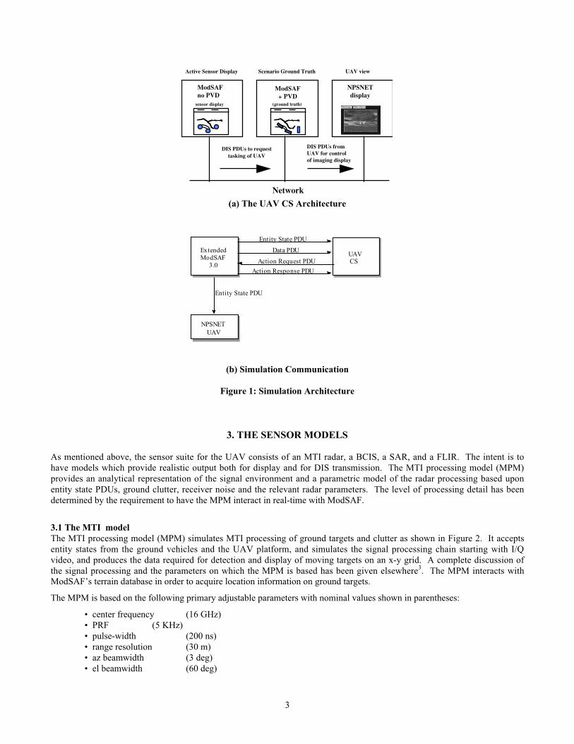
The MSCGS simulation requires the ability to simulate a UAV equipped with an MTI radar and a scanning BCIS. Thesimulation framework has been described in detail elsewhere1. The UAV provides wide-area surveillance for the scenariothrough the use of the MTI radar and the BCIS. Within the simulation, the CGS operator has the ability to designate a trackand to forward that designation to the UAV causing it to perform a surveillance mission. The high-resolution imagery isavailable to the operator at a separate display. The UAV CS provides the capability to control the UAV from withinModSAF by means of the ModSAF plan view display (PVD) as shown in Figure 1(a). The PVD gives a two-dimensionaliconic view of the battlespace, representing vehicles and terrain with simple vector icons. ModSAF running with the PVDrepresents the scenario ground truth i.e. a perfect representation of how the scenario is unfolding in time. The “sensordisplay” is a replication of the terrain shown on the PVD, but shows only the target reports from the MTI and the BCISidentification (friend or unknown). It serves as the UAV CS Display and also as a “surrogate” MSCGS display. The UAVcarries an imaging sensor, and so it will be the entity in ModSAF to which the view will be assigned. At the start of ascenario it will execute an arbitrary loiter orbit until it is assigned its imaging task. Task assignment requests are passed toModSAF by means of DIS Action Request PDUs. This task request takes place when an MTI track is selected for imagingby means of a mouse button click entry. At that time, the UAV will be commanded by the software to fly to anautomatically determined route in order to align itself for the imaging task. A beam footprint whose position, size and shapeis determined by the sensor position, attitude, and field-of-view appears on the sensor display as an indication of therelationship of the image display to the terrain in the operational scenario.
The UAV model described here is an extension to ModSAF 3.0 which is capable of accepting remote route specifications. Bylimiting the ModSAF development to three new libraries, and changing only a few data files, integration with the existingModSAF is kept manageable. Most of the file system for the extended ModSAF consists of symbolic links to the baselineModSAF 3.0 file system. Two new libraries, libbcis and libmti, have been created within the sensor class, and a new tasklibrary was created within the task class. The functionality of these libraries, and an overall description of each as well asmore detail on the extended ModSAF 3.0 can be found in the project documentation2. An additional capability developedfrom NPSNET (Naval Postgraduate Network Vehicle Simulator) provides a visualization of the UAV’s close-in, high-resolution sensor output, thus providing the CGS operator with real-time visualization of the designated target.Communication between the extended ModSAF, the UAV CS and NPSNET is accomplished via standard DIS 2.04 PDUs asshown in Figure 1(b). Extended ModSAF 3.0 and the UAV CGS simulation interact at a low level via the PO (PersistentObject) protocol. The only query that the UAV CGS makes into the PO database is to identify the object type of theMTI/BCIS equipped vehicle (i.e. the UAV) for display within the tactical map. However, more PO interaction could beadded to the software at a later time.
3
ModSAFno PVD
sensor display
ModSAF+ PVD
NPSNETdisplay
Network
DIS PDUs to requesttasking of UAV
DIS PDUs fromUAV for control of imaging display
Active Sensor Display Scenario Ground Truth UAV view
(ground truth)
(a) The UAV CS Architecture
Controller
ExtendedModSAF
3.0
UAVCS
NPSNETUAV
Data PDU
Action Request PDU
Action Response PDU
Entity State PDU
Entity State PDU
(b) Simulation Communication
Figure 1: Simulation Architecture
3. THE SENSOR MODELS
As mentioned above, the sensor suite for the UAV consists of an MTI radar, a BCIS, a SAR, and a FLIR. The intent is tohave models which provide realistic output both for display and for DIS transmission. The MTI processing model (MPM)provides an analytical representation of the signal environment and a parametric model of the radar processing based uponentity state PDUs, ground clutter, receiver noise and the relevant radar parameters. The level of processing detail has beendetermined by the requirement to have the MPM interact in real-time with ModSAF.
3.1 The MTI modelThe MTI processing model (MPM) simulates MTI processing of ground targets and clutter as shown in Figure 2. It acceptsentity states from the ground vehicles and the UAV platform, and simulates the signal processing chain starting with I/Qvideo, and produces the data required for detection and display of moving targets on an x-y grid. A complete discussion ofthe signal processing and the parameters on which the MPM is based has been given elsewhere3. The MPM interacts withModSAF’s terrain database in order to acquire location information on ground targets.
The MPM is based on the following primary adjustable parameters with nominal values shown in parentheses:
• center frequency (16 GHz)• PRF (5 KHz)• pulse-width (200 ns)• range resolution (30 m)• az beamwidth (3 deg)• el beamwidth (60 deg)

4
• sweep rate (36 deg/sec)
These parameters are stored in a file and read when the model is instantiated. The parameters are stored as ASCII text toallow changes to these values without the need for recompilation.
signal +
ground clutter&
noise
clutterfilter
Dopplerprocessing
CFARDetection
targetreports
Figure 2: MTI Processing Diagram
The MPM performs the following processing functions:
• Generate samples of band-limited Gaussian ground clutter.
• Embed each target in a clutter cell. Targets are point reflectors either constant or Swerling II.
• Clutter filter operation.
• Doppler processing performed by an FFT whose size depends on the number of pulses which the radar coherentlyintegrates.
• Perform CFAR detection in each target cell.
• Declare target detection based on "m out of n" threshold crossings.
3.2 The BCIS ModelBCIS is a query and answer (Q&A) system which is designed to reduce fratricide and increase situational awareness (SA) offriendly forces in tactical battlefield scenarios. The BCIS interrogator transmits a digitally-modulated, frequency-hoppedsignal. The main path is line-of-sight (LOS) with free-space, atmosphere, and rain loss as well as potential foliage and terrainblockage. For the UAV application, a model of the ground-to-ground BCIS system is “mounted” on-board and operated in ascanning mode which is more appropriate for the intended application, i.e. to use BCIS as a source of SA information ratherthan for point-of-engagement ID. This model incorporates the propagation losses, LOS blockage from terrain features, andprobabilistic features of bit-error rate and transmitter/receiver characteristics. The scan is selectable as full-revolution orangle-adjustable sector scan. The BCIS display is integrated with the MTI display using appropriate symbology for knownfriendly forces. It is color-coded so that MTI hits are shown in yellow with a “shadow” representing a track of the previous20 scans and the BCIS responses are shown in blue 1.
3.3 The Imaging ModelThe thrust of the current effort is to demonstrate the capability to provide automated control of the UAV mission tasking andthe execution of the imaging task within the simulation. As a consequence, the imaging model is restricted to that providedby a perfect, visible optics 3-dimensional view from the UAV platform. This is accomplished by integrating the simulation

5
with the NPSNET visualization software. Plans are underway to integrate the FLIR capability through the use of the Paintthe Night (PTN) software developed by the US Army Night Vision Electronics Sensor Division (NVESD). The SAR viewwill be executed by means of the XPATCH-ES software developed by the US Air Force Wright Laboratories.
Use of the NPSNET 10.3 software in conjunction with extended ModSAF and the UAV CS provides the user with apowerful visualization tool. Features of NPSNET include:
• DIS 2.03 or 2.04 compliance• User selectable vehicle models including a UAV• Ability to tether to a host vehicle• Real-time out the window display including remote entity and terrain features
Tethering the NPSNET UAV to the UAV created within extended ModSAF allows the user to make real-time observationsas the UAV intercepts the selected target.
The NPSNET software is best described in documentation available from the Naval Postgraduate School5. The onlymodification made to the NPSNET software is the disabling of the Entity State PDU generation for UAVs when in tethermode. Some print statements were added so that the camera angle and field of view would be sent to the terminal window,thus allowing the operator to adjust each of these parameters. The code was revised so that the status block is always drawnfor ground vehicles. Once the NPSNET UAV is tethered to the ModSAF UAV, and the camera angle and field of view havebeen adjusted, the simulation is correctly configured to act as a visualization tool for the UAV CGS simulator. At targetintercept, the observer will be able to see the target within the NPSNET display coincident with the UAV footprintillumination of the target on the UAV CGS tactical map display.
The NPSNET UAV software was built under IRIX 6.2 on an SGI High Impact Indigo 2 and under IRIX 6.4 on an SGIOnyx2. The software was built in compliance with DIS 2.04.
4. UAV MANEUVER & CONTROL
This section describes the logic by which the UAV entity within ModSAF is automatically tasked to perform a fly-over andan imaging task of a designated target track. The target track designation is performed on the UAV CS display by means of acursor placement and mouse click which is the sole operator input. The objective is to automatically reposition the UAV sothat it can perform a “head-to-head” flyover of the designated target(s) for the purpose of image acquisition. An operationalscenario consists of number of moving targets which are following piece-wise linear routes. The UAV is initially in a stand-off loiter orbit. The position and orientation of the loiter orbit is arbitrary except that it is at some minimum distance frompotential targets. The moving targets will be detected by the MTI radar, processed by BCIS to indicate friendlies orunknowns and be represented on the UAV CS display. A mouse click will indicate an imaging request, at which time theUAV will depart its loiter orbit and proceed to align itself for the imaging task in the manner described above. It should benoted that even when a scenario is constructed with straight line routes, the individual entities (vehicles) may deviate fromthese routes in order to perform obstacle avoidance, terrain following and the like. In addition, it is clearly desirable to havethe UAV possess the ability to properly realign itself if the designated target(s) have executed turns after the initialdesignation. In order to account for this variety of scenario, a 4-dimensional linear Kalman filter was incorporated into thesoftware. The purpose of this filter is to provide track and update information on the designated track, and to initiate a UAVmaneuver if a target change in direction of sufficient magnitude is detected. The ground vehicle entity closest to the cursordesignation will be used for tracking purposes. The first task is the determination of a waypoint for the UAV which will serveto position it with respect to the target so that an overhead, “head-to-head” view can be obtained. A simple illustration of thesituation is shown in Figure 3(a). Since the parameters for a particular entity can vary during a scenario, it is important to beable to predict the target track and adjust the UAV waypoint if necessary. Finally, since the imaging sensors have a relativelynarrow field of view (FOV) it will be necessary to adjust the UAV path by a “precision approach” logic to insure maximum“viewability” of the designated target as the UAV flies overhead. This logic will be executed after the UAV has passed overthe current waypoint. The processing scheme is composed of three modules-

6
•Waypoint InitializationUse the input target designation to develop a waypoint for the UAV. The waypoint is determined so that theUAV/target encounter will be “head-to-head”. Task the UAV to go to the computed waypoint, then to follow aroute directly in towards the designated track.
•Track & UpdateDevelop a track of ground position and velocity for the designated target. If the track deviates sufficiently fromthe previous straight-line track segment, then develop a new waypoint for the UAV.
•Precision ApproachOnce the UAV has passed over the waypoint, adjust the UAV path so that it flies as closely as possible to thedesignated target path.
The Track & Update and Precision Approach (where applicable) are executed in a loop on each radar scan.
4.1 Waypoint InitializationWaypoint Initialization consists of the waypoint determination and the maneuver logic which is executed in order to directthe UAV to the waypoint. This waypoint is determined by predicting target motion along its route by a prediction time tpred
determined by an arc joining the ground position of the UAV to the present target position, adjusted for target motion. TheUAV is flying at some known altitude zu above ground level and carries an imaging sensor at some known depression angle εrelative to the platform. Consequently, the horizontal offset of the center of the beam footprint needs to be included in thewaypoint computation.
Pwaypt = PT + VT*tpred + (zu*cotε)*DT (1)
where PT is present target position, VT is target velocity and DT = VT /||VT|| is target heading direction.
The UAV must automatically be directed to fly to Pwaypt. In order to accomplish this, a secondary waypoint P2 has to becomputed in order to determine whether the UAV must execute a complete turn. To this end, the ModSAF topocentriccoordinate system (TCC) is rotated to line up with the target direction DT = (dx,dy). The ground coordinates of the UAV inthe new system are given as-
′P ug = ℜ( P ug − Pwaypt ) (2)
where ℜ =d y −d xd x d y
and Pug = (xu,yu) and P′ug = (x′u,y′u) are the ground coordinates of the UAV relative to the original and rotated frame
respectively. If y’u>0, the UAV can be tasked to fly to directly to Pwaypt , and then along the path determined by -DT. Ify′u < 0, a turn has to be coordinated through the secondary waypoint P2 determined by -
P2 = ∆(Pug-Pwaypt) + Pwaypt (3)
where ∆ =d y
2 −dxd y
−dxd y dx2

7
The processing is illustrated for the case y′u < 0, in Figure 3(b).
Once the UAV is properly aligned for the imaging task, the beam footprint is displayed on the UAV CS display. Fourvertices of a trapezoid are used to represent the beam footprint. These vertices depend on the UAV altitude zu, the sensordepression angle ε and horizontal and vertical fields of view, γ and β respectively. The depiction of this trapezoid on the
display will be barely visible unless the map scale happens to be set to a very low value. To remedy this situation, the displayis set to a fixed size with an option to scale the footprint on the UAV CS Graphical User Interface (GUI).
PT
Puav
initial target position& heading
inital uav position & heading
desired uav waypointposition & heading
VT
Vuav
yTCC
xTCC
PT
P uav
inital uav position & heading
VT
Vuav
y TCC
xTCC
Pwaypt
θT
′ y u
′ x u
P 2
y’
x’
<0
(a) UAV/target encounter geometry (b) UAV maneuver geometry
Figure 3: UAV Mission Geometry
4.2 Track & UpdateThe Track & Update function consists of a 4-dimensional linear Kalman filter whose state vector consists of target groundposition and velocity coordinates.
X = x, y, vx , vy( )t(4)
The tracking filter runs on each radar scan and consists of two phases: state prediction from the previous scan to the currentone and state update of the prediction with the current measurement to resolve any difference between the prediction and the“actual” measurement. The tracking filter uses 4 gains (2 for position, 2 for velocity) to develop estimates of theposition/velocity of the target. These gains depend in turn on the 4 parameters defined in the input quantities σσσσmeas and σσσσmod.
In the state vector notation above, Xn = state on scan n, and
Φ =
1 0 dt 0
0 1 0 dt
0 0 1 0
0 0 0 1
The two processing stages are-
Xnp
= ΦXn−1u
prediction

8
Xnu = Xn
p+ G(Z n − HXn
p) update (5)
Xp and Xu represent predicted and updated quantities respectively, and
H =1 0 0 0
0 1 0 0
and G =gx 0
0 gy
gdx 0
0 gdy
t
(6)
The two gain calculations are 4:
g( ) = 1 + 2r1 + 2r − 1
r
2
and gd( ) =
2
dt
1 + 2r − 1
r
2
where r =4σ( )meas
σ( )mod dt( )2
(7)
In these equations, g( ) stands for either gx or gy depending on whether the corresponding parameter is used for σ( )mod and
σ( )meas in r. Similarly for gd( ). The gains computed here are constant for all radar scans and are computed only once for any
scenario.
The current estimate of velocity Vnp will be used to test for any significant change of direction in the target path. To
accomplish this, a test is made using both the current and the past velocities: Vnp and
Vn-1p. Normalizing both velocities, and computing their dot product:
dot(n) = UVnp
• UVn−1p
where UVp
=V
p
Vp (8)
The quantity dot is used to detect significant changes in target direction. The ideal value of dot = 1 (successive velocitiesperfectly aligned). If dot drops below a threshold value τangle = cos(angle_thresh) then that scan number and the
corresponding direction are flagged. Once dot exceeds τangle, the corresponding unit velocity is used to estimate the change in
direction. This direction change is in turn used to update the UAV intermediate point and waypoint. The vector product isused in order to completely determine the full range of angles.
4.3 Precision ApproachThis module is executed only if the UAV has passed through the most recent waypoint. Once this has occurred, correctionsto the UAV flight path are made which line up the UAV more precisely with the designated target path. If Pclose is the pointon the predicted target path which is closest to the UAV ground position, and sug is the UAV ground speed, P(n)
close = currentPclose is predicted along the desired direction into the next radar scan
P(n+1)close = P(n)
close - sug* dt *UVnp (9)
The UAV is then tasked to go_to_point P(n+1)close, , then follow_route along -RT. This is illustrated in Figure 4.

9
P(n)close.
.
UVpn
(target path)
Vug
(UAV ground path)
.P(n+1)close
d
Figure 4: Precision Approach Geometry
5. SOFTWARE ARCHITECTURE
Due to limitations of space, only a brief overview of the software architecture will be presented here. A much more detailedand complete description is provided in the project documentation2. A schematic of the UAV CS software processing isprovided in Figure 5. In order to initialize UAV CS processing, the DIS and PO networks are opened and the terrain databaseand the default parameters startup file are read. The software then waits for DIS PDU reception, or mouse button events.Once an intercept request has been triggered by the user, a route which ensures that the UAV will fly head-on over the targetis determined. A successful intercept of the target also requires that the beam footprint of the UAV’s imaging sensor passdirectly over the target. In addition, once the UAV is enroute, the target must be monitored so that the UAV’s flight plan canbe automatically adjusted for any changes to the target’s heading. The software uses the algorithms presented in Section 4 todetermine the intercept path and to maintain the display of the UAV’s beam footprint. The intercept method “Intercept byMTI TGT Hits” described here is very general. The MTI data from the operator selected target is used to generate a route.The history of MTI reported positions for that target is extracted and reversed. The route points are then sent to the ModSAFUAV within an Action Request PDU. This method will work for any vehicle having a MTI target hit history. Once the UAVhas completed its’ route, it will begin a loiter orbit above the final point of its route and the representation of the beamfootprint will be removed from the tactical map display.

10
START
waiting for PDUS or mouse input
ES PDU
If from sensor equipped vehicle,
update UAV display
If MTI tgt hit, update MTI list and
update display
Data (MTI) PDU
If BCIS tgt hit, update BCIS list and
update display
Data (BCIS) PDU
Middle orRight MouseButton Click
if middle, zoom inelse pan out
Left MouseButton Click
Determine intercept points and send intercept request.If Data (MTI) PDU received do MTI list+display updateIf Data (BCIS) PDU received do BCIS list and display updateIf ES (UAV) PDU received do UAV display updateIf middle or right mouse click zoom or pan out
Action Request (Intercept Request
WAYPT INIT) PDU
not tracking turn ANDAction Response(Intercept Response PAST_PWAYPT) PDU
Waiting for PDUS or mouse inputIf Data (MTI) PDU received do MTI list+display update do track & update and do precision approachIf Data (BCIS) PDU received do BCIS list and display updateIf ES (UAV) PDU received do UAV display updateIf middle or right mouse click zoom or pan out
Mouse Input - Cancel Intercept ORAction Response (Intercept
Response COMPLETED) PDU
Waiting for PDUS or mouse inputIf Data (MTI) PDU received do MTI list+display update do track & updateIf Data (BCIS) PDU received do BCIS list and display updateIf ES (UAV) PDU received do UAV display updateIf middle or right mouse click zoom or pan out
Action Response(Intercept BEGINResponse) PDU
Action Request (Intercept Request
TRACK_UPDATE) PDU
Action Response(Intercept Response
CHNG_INTRCPT) PDU
Action Request(Intercept Request
TRACK_UPDATE ORPREC_APPR) PDU
tracking turn ANDAction Response
(Intercept Response PAST_PWAYPT) PDU
Action Response(Intercept ResponsePREC_APPR) PDU
Figure 5: Schematic of UAV CS Software Processing
The UAV CS software is GUI driven. The simulation software is coded in C and runs under SGI IRIX 5.3. Start up and runtime GUIs are coded using TCL 7.4 and TK 4.0. The tactical map display uses ModSAF 3.0 libraries. The start up GUIallows the user to specify initialization parameters for the particular exercise. These parameters include:
• DIS port• DIS exercise identifier• DIS protocol version ( either DIS 2.03 or DIS 2.04 )• Persistent Object (PO) port• PO database identifier• Path to the extended ModSAF data directory• Terrain database specification• Name of the default settings file (contains default values for the adjustment to offset Pwaypoint and for the
sigmas within the tracking filter)
The user may adjust these parameters as needed. The DIS, PO, terrain and data file directory parameters should match thoseof the concurrently executing extended ModSAF. The user may save preferences to a file using the File-SaveAs menu.Preferences may then be reloaded at a later time by using the File-Open option. Once the startup parameters are satisfactory,clicking the left mouse button over the “Start Processing” button will continue the simulation. The start-up GUI will beiconified since it is no longer necessary. The run-time GUI and the tactical map display will then be displayed. Additionalinputs available on the run-time GUI include user specification of altitude and speed of the UAV. Preemption of theintercept is possible using the Cancel Intercept button or by selecting another target to intercept. If canceled, the UAV willstop traversal of the intercept route, and reenter a loiter orbit about its present position. Otherwise, the UAV will do theappropriate processing to intercept the new target. Once the UAV has been tasked to intercept a target, the beam footprintfrom the UAV’s high-resolution imagery sensor is drawn on the tactical map display. The operator may use the footprintscale option on the run-time GUI to increase the dimensions of the footprint. Settings are available which will scale thefootprint to 1, 5 or 10 times normal size.
The tactical map display is the primary interface to the UAV CS simulation. A screen shot of this display is shown in Figure6. Within the tactical map, the sensor equipped UAV is represented as a blue fixed wing aircraft icon. Using the Sensors

11
menu, the user may specify which sensor data are presented within the UAV CGS display. The MTI and BCIS sensors areincluded in the list of options. Additional options within the menu, FLIR and SAR, have not yet been implemented. If theBCIS and MTI sensors have been selected, and returns from each of these sensors are received, that sensor data will bepresented within the tactical map. Current MTI returns are presented with circular yellow icons. Previous MTI returns areshown as circular gray icons. The history of MTI hits will generate target tracks on the display. Periodic blue circularoverlays indicate scanning BCIS (i.e. friendly entity) returns. Each BCIS return will be timed out after 5 seconds. If theUAV CS operator determines that an unknown track requires closer scrutiny, the operator may task the UAV to intercept.This is accomplished by clicking the left mouse button on the most recent (i.e. yellow) MTI icon of the unknown track. Theicon closest to the location of the mouse click will determine the target to be intercepted. An intercept request will be issuedto the UAV. If the request is accepted, it will begin traversal of its route. The UAV s beam footprint will be shown as arectangle directly in front of the UAV. The footprint has been designed to be transparent. It will not hide either terrainfeatures or vehicle icons. The true size of the footprint relative to other objects within the tactical map is extremely small soa capability is included which allows the size of the footprint to be scaled to 5x or 10x using the run-time GUI. The interceptroute assigned to the UAV can be seen on the tactical map by selecting the Map Features — Show Intercept Route option.When this option is activated, the UAV flight plan will be shown as a purple route line. A sample snapshot of a fly-over ofthe UAV is shown in Figure 6. This view corresponds to a snapshot of the scenario shown in Figure 5 taken during the timeof target intercept. Three targets and a variety of terrain features are clearly visible.
UAV
MTI Hit
Past MTI Hit
BCIS Hit
Figure 6: UAV CS Tactical Map Display

12
Figure 7: UAV Fly-Over View
6. SUMMARY
A detailed description of a Multisensor Common Ground Station (MSCGS) has been presented. It consists of a multisensorUAV model bundled with UAV Control Station (UAV CS) software which allows the MSCGS operator to task the UAV forimaging missions and view the designated targets within the simulation environment. The next version of the MSCGSsimulation will include real-time synthetic forward looking infrared (FLIR) and synthetic aperture radar (SAR) sceneimagery to complete the multisensor capabilities of the model. Other upgrades will include platform stabilization and astaring capability for the imaging sensor.
7. ACKNOWLEDGEMENTS
The authors wish to acknowledge support from the US Army PM Joint STARS under contract DAAB07-97-C-E601(98).The authors also wish to thank Barney Aviles of the MITRE Corporation for his assistance in preparing the screen viewsfrom NPSNET.
8. REFERENCES
1. J. Roberts, J. SantaPietro, “Model-Based Sensor Rendering for a DIS Multisensor Airborne Surveillance Platform”Visualization of Temporal and Spatial Data for Defense Applications, Vol. 3085, pp. 37-45, Proc. SPIE, Orlando, 1997
2. D. J. V. Pierce, UAV CGS Simulation Software Architecture, MITRE Project 07988675-MS, Feb.1998
3. J. SantaPietro, “A DIS Model for a Multisensor Airborne Platform”, Proc. of 6th Annual Ground Target Modeling &Validation Conference, Vol. 1, pp. 1-9, Houghton MI, August 1995
4. J. SantaPietro, “Terrain Estimation and Clutter Lock Processing for Airborne Radar”, Ultrahigh Resolution Radar, Vol.1875, pp. 96-105, Proc. SPIE, Los Angeles, 1993
5. NPSNET IV.9 User Guide (Documentation v2.0) Naval Postgraduate School, 1996