Visual Studio Architecture Tooling Guide - Windows Studio... · Visual Studio Architecture Tooling...
75
Visual Studio Architecture Tooling Guide Scenarios 2012-07-17 Visual Studio ALM Rangers Jean-Marc Prieur, John Bergman, Willy-Peter Schaub, Raul Guerrero, Eric Golpe, Hosam Karmel, Francisco Fagas, Fermin Cardenas. Microsoft Corporation Visual Studio ALM Rangers This content was created by the Visual Studio ALM Rangers, a special group with members from the Visual Studio Product Team, Microsoft Services, Microsoft Most Valued Professionals (MVPs) and Visual Studio Community Leads.
Transcript of Visual Studio Architecture Tooling Guide - Windows Studio... · Visual Studio Architecture Tooling...

Visual Studio
Architecture Tooling
Guide Scenarios
2012-07-17
Visual Studio ALM Rangers
Jean-Marc Prieur, John Bergman, Willy-Peter Schaub, Raul Guerrero, Eric Golpe, Hosam Karmel, Francisco Fagas, Fermin Cardenas.
Microsoft Corporation
Visual Studio ALM Rangers
This content was created by the Visual Studio ALM Rangers, a special group with members from the Visual
Studio Product Team, Microsoft Services, Microsoft Most Valued Professionals (MVPs) and Visual Studio
Community Leads.
Visual Studio Architecture Tooling Guide - Scenarios
Copyright 2012 Microsoft Corporation Page 2
The information contained in this document represents the current view of Microsoft Corporation on the issues discussed at the date of publication. Because Microsoft must respond to changing market conditions, it should not be interpreted to be a commitment on the part of Microsoft, and Microsoft cannot guarantee the accuracy of any information presented after the date of publication.
This document is for informational purposes only. MICROSOFT MAKES NO WARRANTIES, EXPRESS, IMPLIED OR STATUTORY, AS TO THE INFORMATION IN THIS DOCUMENT.
Microsoft grants you a license to this document under the terms of the Creative Commons
Attribution 3.0 License. All other rights are reserved.
2010-2012 Microsoft Corporation.
Microsoft, Active Directory, Excel, Internet Explorer, SQL Server, Visual Studio, and Windows are trademarks of the Microsoft group of companies.
All other trademarks are property of their respective owners.

Visual Studio Architecture Tooling Guide - Scenarios
Copyright 2012 Microsoft Corporation Page 3
Table of Contents
ACRONYMS ............................................................................................................................................................ 5
INTRODUCTION ..................................................................................................................................................... 6
OVERVIEW ..................................................................................................................................................................... 6 VISUAL STUDIO ALM RANGERS ......................................................................................................................................... 6
SCENARIOS ............................................................................................................................................................ 7
OVERVIEW ..................................................................................................................................................................... 7 Getting ready for a collaborative environment ...................................................................................................... 7 Some core design principles.................................................................................................................................... 8 Embrace a good process for the team .................................................................................................................... 8 Embrace good practices ......................................................................................................................................... 8 Share Artifacts ........................................................................................................................................................ 8 Select the appropriate scenarios from this guide ................................................................................................... 9
SAMPLE CODE USED AS PART OF THE SCENARIOS .................................................................................................................... 9 A VIEW OF ARCHITECTURE SYSTEM STRUCTURES .................................................................................................................... 9 DIAGRAM SUMMARY ..................................................................................................................................................... 10 GUIDANCE … AT A GLANCE .............................................................................................................................................. 11
SCENARIO - I NEED A REUSABLE (REPEATABLE) ARCHITECTURE ........................................................................... 13
OVERVIEW ................................................................................................................................................................... 13 VISUAL STUDIO MODELING PROJECT TEMPLATES ................................................................................................................ 14 USING A CORRECT UML PROFILE ..................................................................................................................................... 18 ADDING TRANSFORMATIONS TO STEREOTYPES .................................................................................................................... 20 ADDING LAYER DIAGRAMS TO THE TEMPLATE MODELING PROJECT .......................................................................................... 21
Existing Layering Patterns .................................................................................................................................... 22 HOW TO SET UP A SOLUTION STRUCTURE THAT IS MAINTAINABLE AND HAS CENTRALIZED ARCHITECTURAL ARTIFACTS ........................ 22
Less is more .......................................................................................................................................................... 22 Version control structure ...................................................................................................................................... 23 Architecture Solution structure ............................................................................................................................. 23
SOLUTION STRUCTURE TEMPLATES .................................................................................................................................... 24 References to shared components........................................................................................................................ 24 References to other parts of the system not in the current solution .................................................................... 25
SCENARIO - I NEED TO START A NEW SYSTEM ..................................................................................................... 27
WORKFLOW ................................................................................................................................................................. 28 IDENTIFY ARCHITECTURE ................................................................................................................................................. 28 IDENTIFY ACTORS, USE CASES AND BUSINESS CONCEPTS ...................................................................................................... 30 IDENTIFY BEHAVIOR ....................................................................................................................................................... 32 REVIEW MODELS .......................................................................................................................................................... 34
SCENARIO - I NEED TO EXPLORE AN EXISTING SYSTEM ........................................................................................ 35
OVERVIEW ................................................................................................................................................................... 35 WORKFLOW ................................................................................................................................................................. 37
Get Implementation Artifacts ............................................................................................................................... 37 Dependency Graphs .............................................................................................................................................. 38 Discovering and preserving the logical architecture using layer diagrams .......................................................... 41 Architecture Explorer ............................................................................................................................................ 42 Solution Explorer ................................................................................................................................................... 42 Sequence Diagrams .............................................................................................................................................. 43 Class Diagrams ..................................................................................................................................................... 44

Visual Studio Architecture Tooling Guide - Scenarios
Copyright 2012 Microsoft Corporation Page 4
Create Other Diagrams ......................................................................................................................................... 45
SCENARIO - I NEED TO ESTABLISH TRACEABILITY ................................................................................................. 47
BRIDGING REQUIREMENT WORK ITEMS TO USE CASE DIAGRAMS ............................................................................................ 47 LINKING FROM A USE CASE TO A WORK ITEM ...................................................................................................................... 48 WORK ITEM TO MODEL ELEMENT BACK LINKING ................................................................................................................. 51 CREATING TRACEABILITY REPORTS .................................................................................................................................... 51 USING TRACEABILITY REPORTS FOR CHANGE IMPACT ANALYSIS ................................................................................................ 51
SCENARIO – I NEED TO VALIDATE A SYSTEM ARCHITECTURE ............................................................................... 53
VALIDATING THE UML MODELS ...................................................................................................................................... 53 USE UML MODELS FOR TESTING ..................................................................................................................................... 58
Considerations ...................................................................................................................................................... 58 VALIDATION OF KEY DESIGN PRINCIPLES AND CONSIDERATIONS ............................................................................................. 59
Considerations ...................................................................................................................................................... 59 Layer Validation .................................................................................................................................................... 59 Manual System Design Validation ........................................................................................................................ 59
SCENARIO - I NEED TO CUSTOMIZE DGML GRAPHS ............................................................................................. 62
OVERVIEW ................................................................................................................................................................... 62 GRAPH ELEMENTS DEFINITION......................................................................................................................................... 63 DGML GENERATION AND CUSTOMIZATION WORKFLOW ...................................................................................................... 64 DGML MANUAL CUSTOMIZATION ................................................................................................................................... 65
SCENARIO - I NEED CREATE A SPECIALIZED LANGUAGE USING DSL TOOLS ........................................................... 67
OVERVIEW ................................................................................................................................................................... 67 What’s mean Domain-Specific Language? ........................................................................................................... 67 When use Domain-Specific Language? ................................................................................................................. 68
PERSONAS ................................................................................................................................................................... 68 DSL LIFE CYCLE ............................................................................................................................................................ 68
Identify Problem Domain ...................................................................................................................................... 69 Domain Analysis ................................................................................................................................................... 69 Modeling............................................................................................................................................................... 69 Implementation .................................................................................................................................................... 70 Deployment .......................................................................................................................................................... 70 Uses the Product ................................................................................................................................................... 70
APPENDIX ............................................................................................................................................................ 72
UML MODEL CHECKLISTS .............................................................................................................................................. 72 Use Cases / activity diagram ................................................................................................................................ 72 Sequence Diagram ................................................................................................................................................ 74 Class Diagram ....................................................................................................................................................... 75

Visual Studio Architecture Tooling Guide - Scenarios
Copyright 2012 Microsoft Corporation Page 5
Acronyms This guide uses the following common acronyms:
ACRONYM DESCRIPTION
HOL Hands On Lab
IIS Internet Information Server
SDK Software Development Kit Includes software and documentation needed to develop applications that are compatible with specified public operating system and component interfaces.
TFS Microsoft Visual Studio Team Foundation Server. The Microsoft change management product for software development. Its components include work item tracking, source code control, policy support and notifications, and report generating capabilities.
TR TechReady is an internal Microsoft technology awareness and readiness event.
VC Version control
WIT Work item tracking
WSS Microsoft Windows SharePoint Services
A Microsoft Web-based team collaboration environment that provides the ability to create and access virtual workspaces for managing documents, discussions, lists, surveys and other important contextual information, such as team member status and presence.

Visual Studio Architecture Tooling Guide - Scenarios
Copyright 2012 Microsoft Corporation Page 6
This guidance should be used in conjunction with the product documentation at
Microsoft Developer Network (MSDN) and
installed with the product.
Introduction
Overview Welcome to the Visual Studio Architecture Guidance.
This guidance discusses scenarios of using Visual Studio Ultimate, primarily focusing on the Modeling tools, to help you understand the tooling and ensure that your software system meets the expected requirements.
The scenarios include understanding and exploring an existing solution, and starting a new solution from scratch. These are both common challenges that any analyst or architect faces. The intent is not to give you an in-depth tour of the product features, but to present you with examples that show how these tools can aid you in common scenarios, and to provide you with practical guidance and checklists.
Visual Studio ALM Rangers This content was created in a Visual Studio ALM Rangers project. Visual Studio ALM Rangers are a special group consisting of members from the Visual Studio Product group, Microsoft Services, Microsoft Most Valued Professionals (MVP) and Visual Studio Community Leads. Their mission is to provide out of band solutions in the form of practical guidance and extensions to the core product line.
This guide targets the “200-300 level” user of Visual Studio Ultimate: an intermediate to advanced user who has in-depth understanding of the product features in a real-world environment. Parts of this guide may also be useful to TFS novices and experts but users at these skill levels are not the focus of this content.

Copyright 2012 Microsoft Corporation Scenarios Overview - Page 7
The objective of the open communication and sharing of ideas is not only to understand the requirements accurately and to come up with the best solution, but more importantly to create a common vision for the solution.
The core focus of this guidance is not to explain all of the Visual Studio features,
but to give practical guidance on using the tooling effectively.
Scenarios
Overview This section provides examples of common situations that teams find themselves in when designing a new solution (green field) or enhancing an existing solution (brown field). The scenarios outlined here should allow teams to quickly understand the architecture tooling and visualization options that are available to them and the scenarios should provide the necessary framework for a team to use the tooling to better address their needs.
It’s important to note that while these scenarios present options to specific situations, it is impossible to define a general approach that is equally valid for all teams operating within different environments and constraints.
To make the most of these scenarios, it’s important to understand how the Visual Studio Modeling tools work. This guidance does not explain how to operate the tools in detail, but rather what you can achieve with them. Please refer to MSDN
1 for
comprehensive information on Visual Studio, Application Lifecycle Management and the architecture tooling.
If you are an experienced and seasoned user of collaborative modeling environments and interested in the core scenarios, we suggest that you skip the overview section and focus on selecting the relevant scenario on page 9.
Getting ready for a collaborative environment
This guidance is focused on practical ways of effectively using Visual Studio 2012 Ultimate and other tools to create a new or revised design as part of application lifecycle management. Before we go into some of the common scenarios, we will briefly divert to getting ready for a collaborative environment, and highlight some of the core design principles which we should embrace when making use of the tools.
A collaborative environment is important as two of our core objectives are to understand the problem domain and to transparently communicate findings and decisions with all stakeholders. Understanding the problem includes: the analysis of the problem domain; identification of requirements; and definition of potential solutions. Transparent collaboration and communication amongst all stakeholders is necessary to understand and communicate the requirements accurately.
To be in a position to effectively communicate both the requirements and the system design and architecture, you can take advantage of tools such as the whiteboard; paper based sketches, UML diagrams, Microsoft Expression Blend Sketchflow presentations, and the Visual Studio Ultimate architecture tools and virtualization features in collaboration workshops.
Common questions that are asked at this point:
1. Who should take part in the collaboration workshops?
Optimally all stakeholders, including Architects, Developers, Testers, Product Managers, Marketing, Customers, Suppliers, Experts / Consultant, and users.
2. What equipment should we prepare?
White boards …there can never be enough whiteboards.
Digital camera to record diagrams and notes made on whiteboards.
Projector, with a high resolution (> 1024x768) to be able to display high-quality and potentially large design diagrams.
Conferencing and collaboration facilities (e.g. Microsoft LiveMeeting2 and unified conference stations) if the
stakeholders are geographically dispersed.
Please refer to Planning and Tracking Projects
3 for more information.
1 http://msdn.microsoft.com 2 http://office.microsoft.com/livemeeting 3 http://msdn.microsoft.com/library/dd286619.aspx
Copyright 2012 Microsoft Corporation Scenarios Overview - Page 8
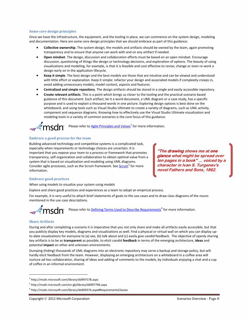
"The drawing shows me at one glance what might be spread over ten pages in a book" … voiced by a character in Ivan S. Turgenev's novel Fathers and Sons, 1862.
Some core design principles
Once we have the infrastructure, the equipment, and the tooling in place, we can commence on the system design, modeling and documentation. Here are some core design principles that we should embrace as part of this guidance:
Collective ownership. The system design, the models and artifacts should be owned by the team, again promoting transparency and to ensure that anyone can work with and on any artifact if needed.
Open mindset. The design, discussion and collaboration efforts must be based on an open mindset. Encourage discussion, questioning of things like design or technology decisions, and exploration of options. The beauty of using visualizations and modeling, for example, is that it is feasible and cost effective to revise, change or even re-work a design early on in the application lifecycle.
Keep it simple. The best design and the best models are those that are intuitive and can be viewed and understood with little effort or explanation. Keep it simple: refactor your design and associated models if complexity creeps in, avoid adding unnecessary models, model content, aspects and features.
Centralized and simple repository. The design artifacts should be stored in a single and easily accessible repository.
Create relevant artifacts. This is a point which brings us closer to the tooling and the practical scenario based guidance of this document. Each artifact, be it a word document, a UML diagram or a case study, has a specific purpose and is used to explain a thousand words in one picture. Exploring design options is best done on the whiteboard, and using tools such as Visual Studio Ultimate to create a variety of diagrams, such as UML activity, component and sequence diagrams. Knowing how to effectively use the Visual Studio Ultimate visualization and modeling tools in a variety of common scenarios is the core focus of this guidance.
Please refer to Agile Principles and Values
4 for more information.
Embrace a good process for the team
Building advanced technology and competitive systems is a complicated task, especially when requirements or technology choices are uncertain. It is important that you expose your team to a process or framework that promotes transparency, self-organization and collaboration to obtain optimal value from a system that is based on visualization and modeling using UML diagrams. Consider agile processes, such as the Scrum framework. See Scrum
5 for more
information.
Embrace good practices
When using models to visualize your system using models
Explore and share good practices and experiences as a team to adopt an empirical process.
For example, it is very useful to attach brief statements of goals to the use cases and to draw class diagrams of the nouns mentioned in the use case descriptions.
Please refer to Defining Terms Used to Describe Requirements
6 for more information.
Share Artifacts
During and after completing a scenario it is imperative that you not only share and make all artifacts easily accessible, but that you publicly display key models, diagrams and visualizations as well. Find a physical or virtual wall on which you can display up-to-date visualizations for everyone to (a) see, (b) talk about and (c) easily give candid feedback. The objective of openly sharing key artifacts is to be as transparent as possible, to elicit candid feedback in terms of the emerging architecture, ideas and potential impact on other and unknown environments.
Dumping (hiding) thousands of UML diagrams into an electronic repository may serve a backup and storage policy, but will hardly elicit feedback from the team. However, displaying an emerging architecture on a whiteboard in a coffee area will nurture ad-hoc collaboration, sharing of ideas and adding of comments to the models, by individuals enjoying a chat and a cup of coffee in an informal environment.
4 http://msdn.microsoft.com/library/dd997578.aspx 5 http://msdn.microsoft.com/en-gb/library/dd997796.aspx 6 http://msdn.microsoft.com/library/dd409376.aspx#RequirementsClasses

Copyright 2012 Microsoft Corporation Scenarios Overview - Page 9
Select the appropriate scenarios from this guide
The scenarios are divided into two main categories, namely “new” and “existing” system scenarios.
The former is concerned with the creation of models for new systems or new documentation, whereas the latter is concerned more with using the tooling to understand an existing system.
Select the appropriate scenario(s) in the preceding diagram and proceed to the relevant page(s) within this guide as per the following reference table:
Scenario Go to page
I need to create a reusable (repeatable) architecture 13
I need to start a new system 27
I need to explore an existing system 35
I need to establish traceability 47
I need to validate a system architecture 53
I need to customize DGML graphs 62
I need to create a specialized language using the DSL tools 67
Table 1 – Scenario References
Sample code used as part of the scenarios The sample code used while preparing this guidance is based on the Microsoft Tailspin sample application, which is available as part of the guidance HOL download
7 and the Pet Shop sample application
8.
A view of architecture system structures Visualizations and diagrams allow you to understand users’ needs and the world in which the system is intended to operate; to define an architecture for the system; to analyze the system; and to ensure that the system meets the requirements.
Before you create visualizations and diagrams it is important to understand how to organize them for best effect.
7 http://go.microsoft.com/fwlink/?LinkID=193441&clcid=0x409 8 http://www.microsoft.com/downloads/details.aspx?FamilyId=E2930625-3C7A-49DC-8655-A8205813D6DB&displaylang=en

Copyright 2012 Microsoft Corporation Scenarios Overview - Page 10
A common approach is to organize diagrams first by type, then by module and - depending on the size of the system - on multiple levels.
The scenarios covered in this document are focused on the organization of the architecture artifacts, for example using the 4+1 model view
9 to organize the design artifacts and an organized solution structure.
Diagram Summary The following table summarizes the diagrams available in Visual Studio Ultimate:
Diagram Description Useful for …
UML Activity Diagram Show workflow of activities and actions. Business process design Algorithms
UML Class Diagram Show class and interface structures, and flow of data between classes
High-level design Requirements concepts
UML Component Show structure of system parts High-level design
UML Use Case Diagram Show the interaction of actors and external systems with the system
Summarize user requirements
UML Sequence Show interaction of objects and sequence of messages High-level design
.Net Sequence Diagram Show interaction of objects and sequence of messages Code analysis
.NET Class Show classes and interfaces in code. Code analysis and visualization Low-level design
Dependency Graphs Show complex structure of your class and the call tree. Code analysis
Layer Diagram Show structure of system at a high level and dependencies between classes
Code analysis Code validation
Please refer to Using Models within the Development Process
10 for more information on MSDN.
9 See http://en.wikipedia.org/wiki/4%2B1_Architectural_View_Model 10 http://msdn.microsoft.com/library/dd409423(v=vs.110).aspx

Copyright 2012 Microsoft Corporation Scenarios Overview - Page 11
Guidance … at a glance
IMPORTANT NOTE
The core scenarios and the view Figure 1 - Core Scenarios at a glance is based on feedback from especially the “Microsoft Most Valued Professionals (MVP)” to ensure that we present guidance that is based on a diverse group that has a good track record of doing architecture for a wide variety of customers in a wide variety of methodologies.
Neither the visualization nor the core scenario guidance intends to show the one and only solution to the problem. As mentioned throughout the guidance it is important that you validate the guidelines against your environment and your practices, adjusting either as appropriate.
Figure 1 - Core Scenarios at a glance summarizes the core scenarios as outlined in this guidance with one of potentially many possible natural flow and transformation from one diagram type to another.
The diagram has nothing to do with any methodology, such as Waterfall, RUP, XP or scrum, and must therefore not be perceived as such. The illustration will re-appear with each core scenario covered in this guidance, with the relevant areas highlighted that we believe are impacted during the scenario.
The illustration Figure 2 - Solution Architecture Modeling Environment, on page 12, is a different view which shows the same guidance from a higher altitude, with no reference to the suggested natural flow and transformation in the core scenario guidance.
Figure 1 - Core Scenarios at a glance

Copyright 2012 Microsoft Corporation Scenarios Overview - Page 12
Figure 2 - Solution Architecture Modeling Environment

Copyright 2012 Microsoft Corporation Scenario - I need a reusable (repeatable) architecture - Page 13
Scenario - I need a reusable (repeatable) architecture
GOAL
Make the architecture process repeatable and well known to your teams. They should know where to find the architecture artifacts so that they can use them later in the project for validation, generation, etc. If you have a physical or virtual wall that is visible to the team, then ensure that the key artifacts (models) are visible to elicit discussions and feedback.
Overview
Figure 3 - Preparing the Environment
In order to successfully implement repeatable architecture using the architecture tools, you need a reference architecture for your problem domain. You can either create your own, or use one provided by the Patterns and Practices Group. You can find a set of reference architecture descriptions at the following location: Application Archetypes
11.
Based on the selected reference architecture you create a set of default transformations from the reference architecture to a set of Visual Studio Solutions to realize the architecture.
This scenario will describe some common steps you can take to create such a repeatable architecture and give you tips and techniques to get you started.
11 http://msdn.microsoft.com/library/ee658107.aspx

Copyright 2012 Microsoft Corporation Scenario - I need a reusable (repeatable) architecture - Page 14
Visual Studio Modeling Project Templates Once you have decided what type of architecture you need for your system, you can start to create the modeling project. To help you produce architectures repeatedly and consistently, you can create a template modeling project from your first one. Later, you can refine it iteratively.
In the modeling project, you describe the architecture in terms of a model. You provide different views on that model using diagrams such as use case, component, activity, sequence and UML class diagrams.
You create a set of artifacts in a modeling project, based on the architecture type of the project and the chosen architectural style. For more information on architecture types, see Application Archetypes
12.
There are two important things to keep in mind when creating an architecture modeling project template.
1. Make sure to have a good UML model structure, so model elements are kept in small version controlled units in the modeling project
2. Enable collaboration between architect and developer by splitting up the solution into projects where the developer and designer can add artifacts. Have one modeling project owned by the architect.
If you take a look at real life projects, you will notice that many applications are composed out of multiple Visual Studio solutions. A good practice is to split your application by layer. A classic rich client application has three distinct layers called User Interface, Business Logic and Data Access. Typically there is also a fourth layer called something like Cross Cutting. Based on these layers you would create four Visual Studio Solutions that all contain one layer implementation. This way the solutions are kept small and this keeps the solutions manageable in the Visual Studio environment.
If you create a Modeling template for this exact same solution, you should create a solution that contains at least 5 modeling projects: one for the architect, and one modeling project for each layer (or coding solution).
The idea behind this is that the architect can now work in the main modeling project, while the modeling projects for each layer are used by the designers and developers of that layer. Each per-layer modeling project is made part of two solutions: the overall modeling solution and the specific layer solution. You can see in the picture below a modeling project for a rich client application Archetype project.
Figure 4 - Modeling Projects and Solution Mapping
12 http://msdn.microsoft.com/en-us/library/ee658107.aspx

Copyright 2012 Microsoft Corporation Scenario - I need a reusable (repeatable) architecture - Page 15
OBSERVATION
One side effect of this approach is that the model projects (and their underlying stores) are independent of each other. This means that if the developer working in the presentation layer creates a class diagram in the respective project, it will not be reflected in the overall architecture model project in the architect’s model store. This is both a blessing and a curse. This way a developer can use modeling capabilities without changing the architecture but on the other hand, the architectural model and design models cannot reference each other. You can, however, synch this manually, or use the extensibility API to write code that could do this programmatically.
Besides this solution structure there is a second part of the modeling project that is important to set up in a standardized structure. This is the package structure you use for the modeling project from the perspective of the UML model.
The structure most commonly used is the so called 4+1 View. See for more details about this way of structuring architecture documentation the following location on the web: 4+1 Architectural View Model
13
If you create an architecture based on the Unified Modeling Process and use the 4+1 view to dissect your architecture artifacts, the following UML model structure would be a good starting point:
Figure 5 - 4+1 Modeling Project
Once you have defined such a structure for the architecture modeling project, you can preserve the whole solution for future use as a template. In order to do this, you can use a plug-in found at the MSDN code gallery that enables you to export a Visual Studio solution as VSIX extension so that it can be instantiated later by other architects in another project.
The plug-in can be found at the following location: Export Template Wizard14
.
VS2012 ALERT | WARNING
The plug-in might not be available for Beta. In that case, you just need to export the template as a zip file (using the existing VS
command in the File menu), and then add the zip file containing the template to a VSIX project (Add Project | Extensibility |
Empty VSIX project).
13 http://en.wikipedia.org/wiki/4%2B1_Architectural_View_Model 14 http://visualstudiogallery.msdn.microsoft.com/57320b20-34a2-42e4-b97e-e615c71aca24

Copyright 2012 Microsoft Corporation Scenario - I need a reusable (repeatable) architecture - Page 16

Copyright 2012 Microsoft Corporation Scenario - I need a reusable (repeatable) architecture - Page 17
The following steps guide you through the process of creating such a template:
RECOMMENDATION
Refer to the “Visual Studio Architecture Guidance – Reusable Architecture HOL15
” for step-by-step walkthrough of this scenario.
1. Start a new modeling project and create a package structure you want to use as template for future projects, such as the structure shown for the rich client application.
2. Now on the File menu there is a new command, Export Template as VSIX. Click this command.
Figure 6 - Export Template as VSIX
3. Select the projects that you want to include in the template.
Figure 7 - VSIX Wizard - Chose Template Type
15 http://go.microsoft.com/fwlink/?LinkId=192799&clcid=0x409
Copyright 2012 Microsoft Corporation Scenario - I need a reusable (repeatable) architecture - Page 18
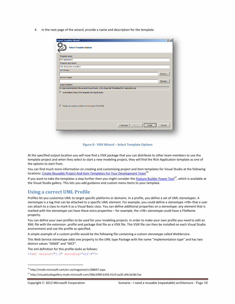
4. In the next page of the wizard, provide a name and description for the template.
Figure 8 - VSIX Wizard – Select Template Options
At the specified output location you will now find a VSIX package that you can distribute to other team members to use the template project and when they select to start a new modeling project, they will find the Rich Application template as one of the options to start from.
You can find much more information on creating and customizing project and item templates for Visual Studio at the following locations: Create Reusable Project And Item Templates For Your Development Team
16
If you want to take the templates a step further then you might consider the Feature Builder Power Tool17
, which is available at the Visual Studio gallery. This lets you add guidance and custom menu items to your template.
Using a correct UML Profile Profiles let you customize UML to target specific platforms or domains. In a profile, you define a set of UML stereotypes. A stereotype is a tag that can be attached to a specific UML element. For example, you could define a stereotype «VB» that a user can attach to a class to mark it as a Visual Basic class. You can define additional properties on a stereotype: any element that is marked with the stereotype can have these extra properties – for example, the «VB» stereotype could have a FileName property.
You can define your own profiles to be used for your modeling projects. In order to make your own profile you need to edit an XML file with the extension .profile and package that file as a VSIX file. This VSIX file can then be installed on each Visual Studio environment and use the profile as specified.
A simple example of a custom profile would be the following file containing a custom stereotype called WebService.
This Web Service stereotype adds one property to the UML type Package with the name “implementation type” and has two distinct values “ASMX” and “WCF”.
The xml definition for this profile looks as follows:
<?xml version="1.0" encoding="utf-8"?>
16 http://msdn.microsoft.com/en-us/magazine/cc188697.aspx 17 http://visualstudiogallery.msdn.microsoft.com/396c5990-6356-41c0-aa20-af4c3e58c7ae

Copyright 2012 Microsoft Corporation Scenario - I need a reusable (repeatable) architecture - Page 19
<profile dslVersion="1.0.0.0" name="RangerProfile" displayName="Ranger Profile"
xmlns="http://schemas.microsoft.com/UML2.1.2/ProfileDefinition">
<stereotypes>
<!-- Web Service -->
<stereotype name="WebService" displayName="Web Service">
<metaclasses>
<metaclassMoniker name="/RangerProfile/Microsoft.VisualStudio.Uml.Classes.IPackage" />
</metaclasses>
<properties>
<property name="ImplementationType" displayName="Implementation Type">
<propertyType>
<enumerationTypeMoniker name="/RangerProfile/Implementationtype"/>
</propertyType>
</property>
</properties>
</stereotype>
</stereotypes>
<!-- All metaclasses referenced by a stereotype defined in this profile -->
<metaclasses>
<metaclass name="Microsoft.VisualStudio.Uml.Classes.IPackage" />
</metaclasses>
<!-- Property Types referenced by a stereotype property defined in this profile -->
<propertyTypes>
<enumerationType name="Implementationtype">
<enumerationLiterals>
<enumerationLiteral name="ASMX" displayName="ASMX" />
<enumerationLiteral name="WCF" displayName="WCF" />
</enumerationLiterals>
</enumerationType>
</propertyTypes>
</profile>
After installing this profile, we can use this stereotype in our models.
For more details, see: How to: Define a Profile to Extend UML18
.
You can generate code from UML models. When you generate code, the stereotypes provide the user with a way to vary the code that is generated – for example, to generate either a web service or a Visual Basic class from a UML class. For more information, see How to Generate Code from a UML Model
19.
18
http://msdn.microsoft.com/library/dd465143(v=vs.110).aspx 19
http://msdn.microsoft.com/library/ee329480(v=vs.110).aspx
Copyright 2012 Microsoft Corporation Scenario - I need a reusable (repeatable) architecture - Page 20
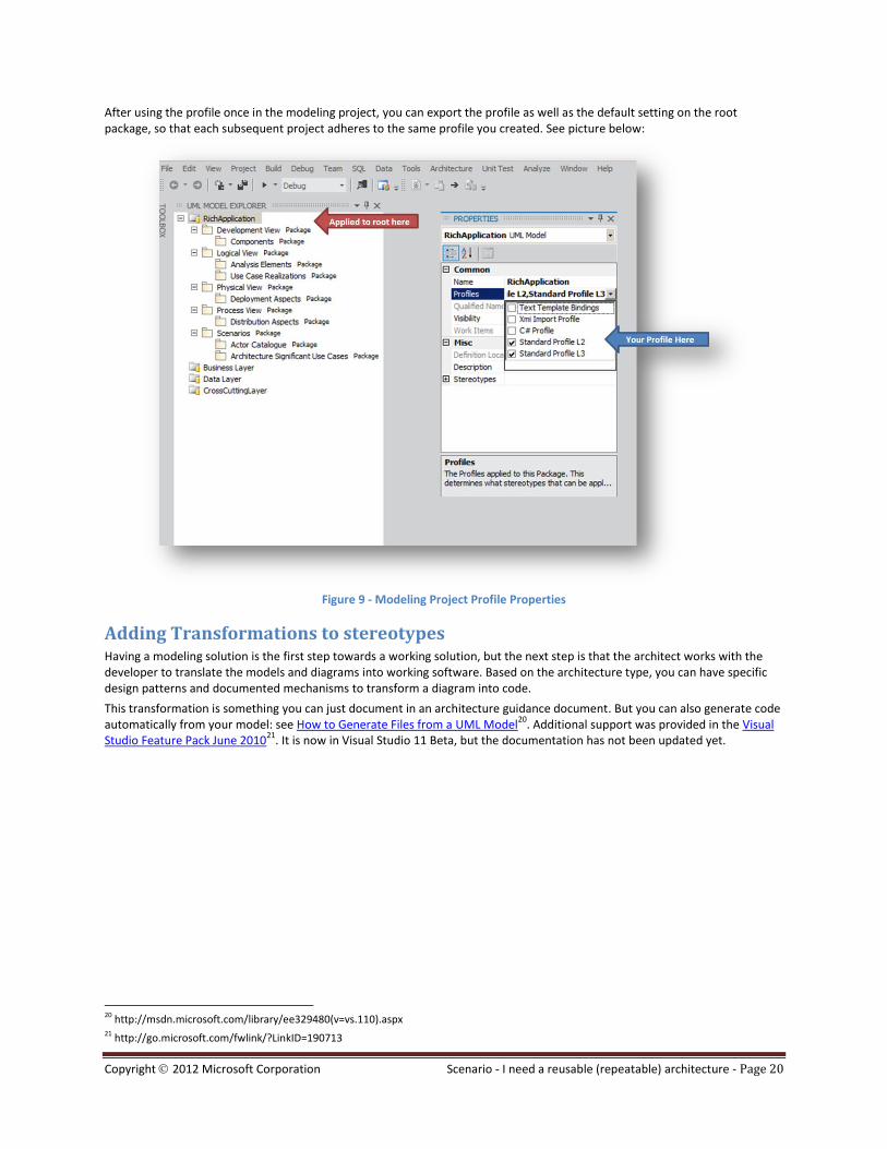
After using the profile once in the modeling project, you can export the profile as well as the default setting on the root package, so that each subsequent project adheres to the same profile you created. See picture below:
Figure 9 - Modeling Project Profile Properties
Adding Transformations to stereotypes Having a modeling solution is the first step towards a working solution, but the next step is that the architect works with the developer to translate the models and diagrams into working software. Based on the architecture type, you can have specific design patterns and documented mechanisms to transform a diagram into code.
This transformation is something you can just document in an architecture guidance document. But you can also generate code automatically from your model: see How to Generate Files from a UML Model
20. Additional support was provided in the Visual
Studio Feature Pack June 201021
. It is now in Visual Studio 11 Beta, but the documentation has not been updated yet.
20 http://msdn.microsoft.com/library/ee329480(v=vs.110).aspx 21 http://go.microsoft.com/fwlink/?LinkID=190713

Copyright 2012 Microsoft Corporation Scenario - I need a reusable (repeatable) architecture - Page 21
RECOMMENDATION
The concept of code generation from diagrams, and analyzing of code to diagrams will be covered in future versions of the Rangers Architecture Guidance and Hands-on-Lab (HOL) walkthroughs.
Adding Layer Diagrams to the template modeling project Layer validation helps you not only define the architecture of your application but also help you maintain the integrity of the architecture throughout its lifecycle.
For this purpose you use Layer Diagrams. These depict dependencies between parts of your code.
Figure 10 - Layer Diagram as part of template modeling project
Developers can validate code against layer diagrams as part of the check-in process. If the actual dependencies in the code violate the scheme depicted in the layer model, an error is raised during the check-in process. In order to achieve this, the layer model for each code solution must be in a project that is part of that solution.
In addition, you can place all the layer models in an overall architecture solution (so that each layer model appears in two solutions). This allows the architect to work with all the layer diagrams together.
In order to have a repeatable architecture pattern you can also save the layer diagrams you create as a template. Refer to the Visual Studio Architecture Guidance - Extensibility Layer Diagrams – HOL
22, which walks through this specific scenario of
creating and saving the layer diagram as a template.
22 http://go.microsoft.com/fwlink/?LinkId=192799&clcid=0x409
Copyright 2012 Microsoft Corporation Scenario - I need a reusable (repeatable) architecture - Page 22
Existing Layering Patterns
You can download a set of predefined application architectures in the form of layer models. These models are based on the Microsoft best practices guidance Microsoft Application Architecture Guide 2
nd Edition
23.
You can download them from Application Architecture Guide Layer Diagrams24
. The current set of application architectures in this set includes:
Web Application
Rich Client Application
Rich Internet Application
Services Application
Mobile Application
How to set up a Solution structure that is maintainable and has centralized architectural artifacts The goal is to enable you to create a Visual Studio structure for your architecture that is maintainable and has a central location for all artifacts created and maintained by the architect. By doing this you can also set more restrictive permissions on certain artifacts under version control to make sure the architecture artifacts are not altered by developers and only maintained by the architect. This is an opt-in model; by default all version control users will have the rights to modify architecture artifacts.
NOTE
Nothing prevents you from creating multiple solutions, all of which could reference the same projects.
Less is more
If you want a Visual Studio solution to be efficient and provide the developers with the best possible experience, you should keep the number of projects in a solution as low as possible. This specific guidance is based on feedback from the Microsoft Most Valued Professionals (MVPs) in the field and suggests a general rule to avoid having more than 10 projects in a solution to maintain performance and maintainability.
If you are building a system that spans multiple departments, it is also a good practice to keep the solutions small and structured in such a way that the departments can maintain and evolve their specific parts of the system separately over time.
IMPORTANT NOTE
The guideline around solution size and structure is based on feedback from the “Microsoft Most Valued Professionals (MVP)” to ensure that you are in a position to use the tools in a way that will help you do a better job and have a better experience. It is important to highlight that the guidance is not a policy, mandate or best practice, but one of many possible views from the field. You need to validate the guidelines against your environment and your practices, adjusting either as appropriate.
With Visual Studio 2010 and earlier versions, loading a solution file with a large number of projects tend to take a considerable time to open them, especially when using Version Control, which negatively impacts overall performance. Obviously the more capable that your server and developer desktop hardware is, the less latency users will experience when loading solution files and their projects. Visual Studio 2012 has introduced the “Async Solution Load (ASL), which loads projects in the background.
While it is feasible to have one solution file that contains all of the projects that make up a system for overall reference and especially for build tasks, it is recommended to create system views by creating more granular solutions. As shown below we can create different views on a complete system, thereby narrowing down the projects, improving overall performance and most importantly promoting focused maintenance. A feature team focusing on Project 3 and 6, will therefore be better served loading solution X.3, than the complete solution X.
23 http://msdn.microsoft.com/library/ff650706.aspx 24 http://visualstudiogallery.msdn.microsoft.com/237f823c-45b4-4f1f-b9e2-607fe66eaae7

Copyright 2012 Microsoft Corporation Scenario - I need a reusable (repeatable) architecture - Page 23
Figure 11 - Breaking a solution in multiple solutions
There are many different other reasons not to bloat solutions with hundreds of projects, such as not including files, such as Test Run Configurations, to avoid continuous merge conflicts when checking in your code, as the tools tend to change them while you work.
Version control structure
The goal is that developers are able to leverage Architectural artifacts in the solutions while the actual architect can build and maintain the architectural artifacts from its own solution. Therefore the following solution structure is the best to meet these requirements:
- Product
- xx-<Layer Solution 1>
- xx-< Layer Solution 2>
- xx-< Layer Solution 3>
- xx-< Layer Solution x>
- 98- Modeling Solution
- 99- Shared
Architecture Solution structure
In order to create a good and maintainable architecture solution the following solution structure can be used:
- Modeling Solution o Layer Modeling Project Layer 1 o Layer Modeling Project Layer 2 o Layer Modeling Project Layer X o Main Modeling Project
UML Diagrams
The structure is organized in such a way that the each layer diagram is placed in its own Visual Studio modeling project. This project is then included in both the Modeling Solution as well in its own Layer Solution. This way there is an overview solution that is used to design the architecture of the application, but also a separate solution for the development of each layer.
SECURING THE ASSETS
You can decide to restrict layer diagram changes to only the architect. This can be done by placing specific permissions on the Layering model project in version control.

Copyright 2012 Microsoft Corporation Scenario - I need a reusable (repeatable) architecture - Page 24
Solution structure templates
Based on the chosen architecture you can start building your application.
You start by creating a new Visual Studio Solution for each of the components you have identified in your architecture and have described using a component diagram. You create each solution from a Visual Studio solution template, which you choose based on the type of the component. As described on page 14, Visual Studio has the option to save a solution as a template, which is something you should do for each component type in your reference architecture.
Based on the component you want to create, these templates have already baked in all your best practices like the sharing of assemblies, a shared sign key, naming patterns and a pre-defined folder structure for your solution. You can see below a sample solution that you could use for the creation of a web service component. This project template has a clean structure that you can use for all of your services.
Figure 12 - Sample solution for the creation of a web service component
References to shared components
You should store in a shared location assets such as the signing key, the assembly info file, and the schema files.
Copyright 2012 Microsoft Corporation Scenario - I need a reusable (repeatable) architecture - Page 25
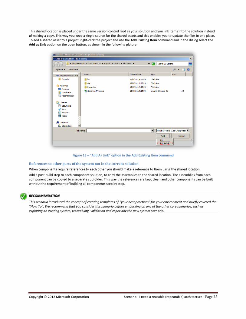
This shared location is placed under the same version control root as your solution and you link items into the solution instead of making a copy. This way you keep a single source for the shared assets and this enables you to update the files in one place. To add a shared asset to a project, right-click the project and use the Add Existing Item command and in the dialog select the Add as Link option on the open button, as shown in the following picture.
Figure 13 – “Add As Link” option in the Add Existing Item command
References to other parts of the system not in the current solution
When components require references to each other you should make a reference to them using the shared location.
Add a post build step to each component solution, to copy the assemblies to the shared location. The assemblies from each component can be copied to a separate subfolder. This way the references are kept clean and other components can be built without the requirement of building all components step by step.
RECOMMENDATION
This scenario introduced the concept of creating templates of “your best practices” for your environment and briefly covered the “How To”. We recommend that you consider this scenario before embarking on any of the other core scenarios, such as exploring an existing system, traceability, validation and especially the new system scenario.


Copyright 2012 Microsoft Corporation Scenario - I need to start a new system - Page 27
Scenario - I need to start a new system
RECOMMENDATION
We recommend that you consider the “Scenario - I need a reusable (repeatable) architecture” scenario before proceeding with
the new system scenario.
Visual Studio Ultimate helps gets you on your way to successfully building a new system. The combination of the Unified Model Language (UML) tools and an iterative approach can help you incrementally:
Identify Requirements
Create a layered architecture with suitable abstractions for an object-oriented approach
Develop the flow of control between components and classes
The requirements for a new system determine what needs to be built. The set of requirements help us to define the architecture for the system. Form follows function. Once we have the form or architecture for the system, we can satisfy each of the requirements by building the flows across the components and classes.
A clean architecture is critical for an extensible and maintainable system. Visual Studio Ultimate provides visibility into the architecture so that everyone in the team can see its elegance. This is critical for larger systems but just as important for a one or two person project.
Figure 14- The New System Scenario Workflow
Whether your project is developed by three people or three hundred, the flow of information across subsystems, components, or classes is important to integrating the system. Flows can be used to communicate intent, model protocols between systems, the contracts between interfaces, or the sequence of messages.

Copyright 2012 Microsoft Corporation Scenario - I need to start a new system - Page 28
It is recommend that you take an iterative approach and avoid trying to model the entire system in one big effort (“Big Design Up Front”). Create an outline model in the first iterative cycle, and then in each subsequent iteration, fill in the details of the functionality that will be addressed in that iteration. Develop tests that reflect the models as closely as possible and validate the code against these tests. Feed lessons learned through coding back to the models. In this way, the modeling process and the development process are kept in sync through an iterative approach.
Workflow There are five main work streams to the new system scenario, which we can relate back to Figure 14, page 27:
Identify Architecture – This work stream contains activities for synergizing the form of the system: layers, components, and classes
Identify Actors/Use Cases – This work stream contains activities by which we determine the users and their goals for the system
Identify Behavior – This work stream contains activities for identifying the dynamic behavior of the system and associated architecture
Review Models – This work stream allows other members of the team to provide input and comments on the architecture model
Develop System – This work stream contains the necessary process for developing a piece of the model and providing feedback so that future modeling efforts stay in sync with the code
These five work streams provide a complete process for modeling a new system. Since each one builds on the others and provides feedback back, mistakes are easily caught downstream and fixed. Work item linking allows development tasks and test cases to be created from the models and linked to provide traceability. Note that the workstreams can operate concurrently – you do not need to complete one before starting the others.
Identify Architecture Many application types follow established architectural patterns. These patterns provide you with standard solutions that have good engineering characteristics such as clean separation of concerns. Using familiar patterns makes it easier for developers to understand an application and to find different parts of the functionality. For example, the layer diagram in Figure 15 could be applied to just about any web application. However, applying this pattern to the Pet Shop sample application
25 keeps our
architecture clean, at least at the highest level.
25 http://www.microsoft.com/downloads/details.aspx?FamilyId=E2930625-3C7A-49DC-8655-A8205813D6DB&displaylang=en

Copyright 2012 Microsoft Corporation Scenario - I need to start a new system - Page 29
Figure 15 -The Online Pet Shop high level layered architecture
Once this pattern is applied, you can break your system into subsystems. For larger systems, subsystems may be assigned to a team or department. On smaller systems, a subsystem may have one or two owners. Of course, when using a software development process with universal code ownership, subsystems may be created for identification purposes and to keep the code base in order. The subsystems often are used to shape our Visual Studio solutions.
Copyright 2012 Microsoft Corporation Scenario - I need to start a new system - Page 30
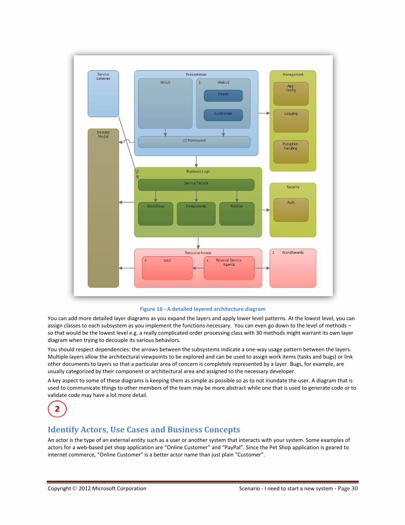
Figure 16 - A detailed layered architecture diagram
You can add more detailed layer diagrams as you expand the layers and apply lower level patterns. At the lowest level, you can assign classes to each subsystem as you implement the functions necessary. You can even go down to the level of methods – so that would be the lowest level e.g. a really complicated order processing class with 30 methods might warrant its own layer diagram when trying to decouple its various behaviors.
You should respect dependencies: the arrows between the subsystems indicate a one-way usage pattern between the layers. Multiple layers allow the architectural viewpoints to be explored and can be used to assign work items (tasks and bugs) or link other documents to layers so that a particular area of concern is completely represented by a layer. Bugs, for example, are usually categorized by their component or architectural area and assigned to the necessary developer.
A key aspect to some of these diagrams is keeping them as simple as possible so as to not inundate the user. A diagram that is used to communicate things to other members of the team may be more abstract while one that is used to generate code or to validate code may have a lot more detail.
Identify Actors, Use Cases and Business Concepts An actor is the type of an external entity such as a user or another system that interacts with your system. Some examples of actors for a web-based pet shop application are “Online Customer” and “PayPal”. Since the Pet Shop application is geared to internet commerce, “Online Customer” is a better actor name than just plain “Customer”.
Copyright 2012 Microsoft Corporation Scenario - I need to start a new system - Page 31
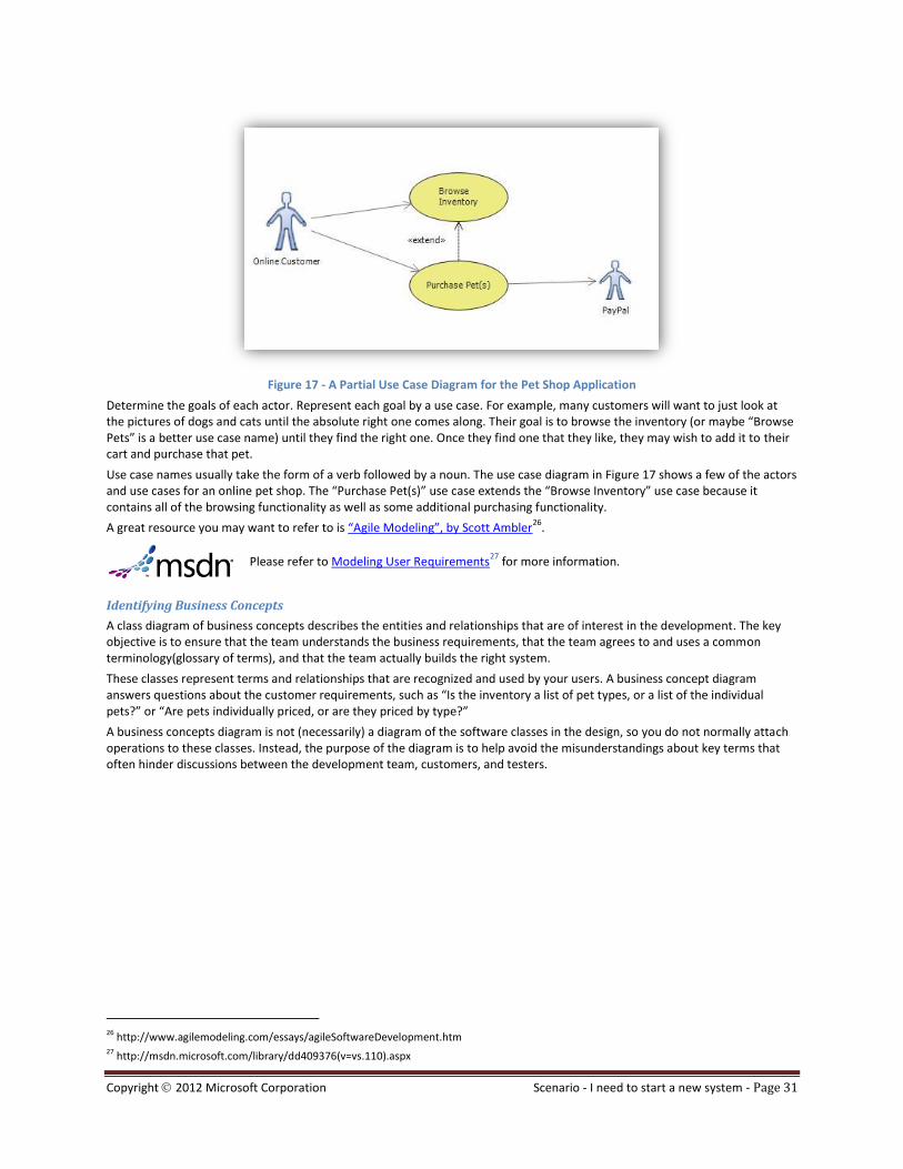
Figure 17 - A Partial Use Case Diagram for the Pet Shop Application
Determine the goals of each actor. Represent each goal by a use case. For example, many customers will want to just look at the pictures of dogs and cats until the absolute right one comes along. Their goal is to browse the inventory (or maybe “Browse Pets” is a better use case name) until they find the right one. Once they find one that they like, they may wish to add it to their cart and purchase that pet.
Use case names usually take the form of a verb followed by a noun. The use case diagram in Figure 17 shows a few of the actors and use cases for an online pet shop. The “Purchase Pet(s)” use case extends the “Browse Inventory” use case because it contains all of the browsing functionality as well as some additional purchasing functionality.
A great resource you may want to refer to is “Agile Modeling”, by Scott Ambler26
.
Please refer to Modeling User Requirements
27 for more information.
Identifying Business Concepts
A class diagram of business concepts describes the entities and relationships that are of interest in the development. The key objective is to ensure that the team understands the business requirements, that the team agrees to and uses a common terminology(glossary of terms), and that the team actually builds the right system.
These classes represent terms and relationships that are recognized and used by your users. A business concept diagram answers questions about the customer requirements, such as “Is the inventory a list of pet types, or a list of the individual pets?” or “Are pets individually priced, or are they priced by type?”
A business concepts diagram is not (necessarily) a diagram of the software classes in the design, so you do not normally attach operations to these classes. Instead, the purpose of the diagram is to help avoid the misunderstandings about key terms that often hinder discussions between the development team, customers, and testers.
26 http://www.agilemodeling.com/essays/agileSoftwareDevelopment.htm 27 http://msdn.microsoft.com/library/dd409376(v=vs.110).aspx
Copyright 2012 Microsoft Corporation Scenario - I need to start a new system - Page 32
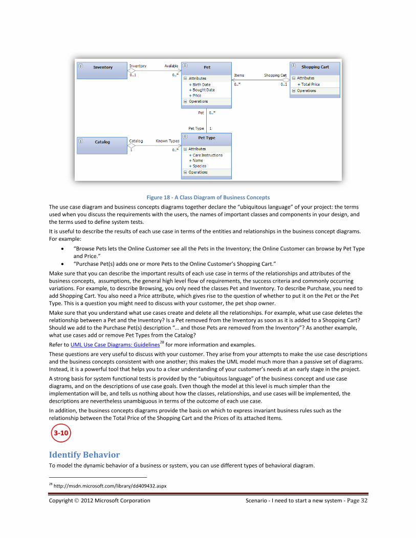
Figure 18 - A Class Diagram of Business Concepts
The use case diagram and business concepts diagrams together declare the “ubiquitous language” of your project: the terms used when you discuss the requirements with the users, the names of important classes and components in your design, and the terms used to define system tests.
It is useful to describe the results of each use case in terms of the entities and relationships in the business concept diagrams. For example:
“Browse Pets lets the Online Customer see all the Pets in the Inventory; the Online Customer can browse by Pet Type and Price.”
“Purchase Pet(s) adds one or more Pets to the Online Customer’s Shopping Cart.”
Make sure that you can describe the important results of each use case in terms of the relationships and attributes of the business concepts, assumptions, the general high level flow of requirements, the success criteria and commonly occurring variations. For example, to describe Browsing, you only need the classes Pet and Inventory. To describe Purchase, you need to add Shopping Cart. You also need a Price attribute, which gives rise to the question of whether to put it on the Pet or the Pet Type. This is a question you might need to discuss with your customer, the pet shop owner.
Make sure that you understand what use cases create and delete all the relationships. For example, what use case deletes the relationship between a Pet and the Inventory? Is a Pet removed from the Inventory as soon as it is added to a Shopping Cart? Should we add to the Purchase Pet(s) description “… and those Pets are removed from the Inventory”? As another example, what use cases add or remove Pet Types from the Catalog?
Refer to UML Use Case Diagrams: Guidelines28
for more information and examples.
These questions are very useful to discuss with your customer. They arise from your attempts to make the use case descriptions and the business concepts consistent with one another; this makes the UML model much more than a passive set of diagrams. Instead, it is a powerful tool that helps you to a clear understanding of your customer’s needs at an early stage in the project.
A strong basis for system functional tests is provided by the “ubiquitous language” of the business concept and use case diagrams, and on the descriptions of use case goals. Even though the model at this level is much simpler than the implementation will be, and tells us nothing about how the classes, relationships, and use cases will be implemented, the descriptions are nevertheless unambiguous in terms of the outcome of each use case.
In addition, the business concepts diagrams provide the basis on which to express invariant business rules such as the relationship between the Total Price of the Shopping Cart and the Prices of its attached Items.
Identify Behavior To model the dynamic behavior of a business or system, you can use different types of behavioral diagram.
28 http://msdn.microsoft.com/library/dd409432.aspx

Copyright 2012 Microsoft Corporation Scenario - I need to start a new system - Page 33
Activity diagrams are used to describe the flow of events at a business level in the use case, and are particularly useful to help you describe concurrent activities. Use cases are often “fleshed out” using activity diagrams.
UML Sequence diagrams are particularly good for showing how the work is distributed between different actors and system components. For each use case, you can draw a sequence diagram in which the lifelines are the actors and the system or its major components, and which shows how they interact to achieve the goal of the use case.
When you design a component as a composition of several parts, you can draw sequence diagrams in which each part is lifeline. For each call to the component’s external interfaces, you can show how the parts interact to achieve the result required for the call. As your project works through the development of different parts of the system, you gradually introduce new diagrams to describe the new components.
You often update these diagrams during implementation. While coding, the diagrams help the team to discuss and discover new paths and to refactor methods and classes.
Two types of sequence diagram are supported by Visual Studio Ultimate. UML sequence diagrams form part of a UML model.
.NET sequence diagrams are generated from program code, use the familiar UML notation and are not part of a UML model. While you are developed some code, you can generate sequence diagrams to review its structure, compare it with the design that was originally intended, and discuss alternative distributions of responsibility.
Figure 19 - The .Net Sequence Diagram generated from ProcessOrder in the Pet Shop application

Copyright 2012 Microsoft Corporation Scenario - I need to start a new system - Page 34
Review Models Each model provides a different perspective view of the system. A complete picture of the system is obtained when all of the models are brought together and reviewed. Continuous model reviews are a great place to challenge assumptions and understand each other’s points of view. In the review, work to implement the model in code in code can be assigned using work items. TFS can be used for collaborating on the expansion of the models and models can be linked to work items.
Visual Studio 2012 includes the new feature where work items can link back to models and this is vital for this kind of process. Agreeing to and using colors, comments and work item links is another useful strategy to support the reviewing of models and diagrams.
RECOMMENDATION
Refer to the “Visual Studio 2012 Architecture Guidance – New System HOL29
” for step-by-step walkthrough of this scenario.
29 http://go.microsoft.com/fwlink/?LinkId=192799&clcid=0x409

Copyright 2012 Microsoft Corporation Scenario - I need explore an existing system - Page 35
Scenario - I need to explore an existing system
Figure 20 – Explore an existing system Scenario Hotspots
Overview In the past we had to use the Solution Explorer and a variety of tools, such as Microsoft Visio, to derive the architectural design from the projects and code files collections, and rely on the project and file naming conventions. The process was often difficult, error prone and non-standard, resulting in reverse engineered designs and visualizations that were often outdated, incomplete or inaccurate. In essence the process was often “manual” and the more we can automate the laborious and error prone processes, the better our understanding of the models.
Visual Studio Ultimate can help us in a analyzing an existing system scenario in situations such as:
We need to understand (parts of) the existing system to be able to maintain or extend it.
We need to understand (parts of) the existing system to be able to tell something about its quality.
The architecture tools in Visual Studio Ultimate help us to visualize the organization, relationships, design patterns and behavior of (parts of) an existing software system in a consistent, repeatable and standardized manner.
Please refer to Exploring Existing Code
30 for more information on MSDN.
30 http://msdn.microsoft.com/library/dd409365(v=vs.110).aspx

Copyright 2012 Microsoft Corporation Scenario - I need explore an existing system - Page 36
QUESTIONS
Why is it important to identify the design patterns that are used in an existing system?
Why do we need a high-level design view?
If you want to extend or change the behavior of an application, it is important first to understand what all its parts are, what they do, and how they depend on each other. This is necessary not only so that you can identify which parts need to be changed, but also so that you can assess how far any change that you might consider would affect the rest of the design.
The relationships between the parts of a complex design can be described in terms of design patterns. For example, you might identify one object as an observer of another. Once you have identified these patterns, the intention of the original designer becomes clearer. It is then easier to keep to the original design principles while you adapt and extend the design.
While exploring existing code, you might find areas where the design could be improved to make the design easier to change. These can be identified and described in terms of anti-patterns such as circular dependencies or duplication. Describing any shortcomings as anti-patterns makes it easier to assess the degree of difficulty they might cause, and to discuss possible resolutions.
In case of a new requirement or feature you need to understand how the new parts will interact with the existing functions, and how much of the existing code will have to be changed. The exploratory reverse engineering process embraces two forms of understanding:
1. To detect patterns and the general structure of an application at a high level.
2. To understanding a method or a particular flow in detail at a lower level of detail.
You can generate sequence diagrams from the existing code, and then modify them to implement the new use cases. From these adapted diagrams, you can get the required interfaces for each component. You can also assess the impact of the changes on the quality of service requirements of the system.
QUESTIONS
How do we start with the reverse engineering scenario?
It depends on the type and level of details you need.
For example:
To explore existing code dependencies with the intent to identify circular references or dependencies between assemblies or namespaces, you should generate a Dependency Graph.
To describe the structure of an application at a high level, and to verify that the detailed code conforms to this high-level design you should create a Layer Diagram.
To get a system overview or find existing code you should use the Architecture Explorer or Solution Explorer.
To explore a sequence of messages between typical instances of classes you should generate a Sequence Diagram.
To see the class structure from existing code you should generate a Class Diagram.
To visualize the system in major blocks to help the development team to understand an existing design and to evolve the design you should create a Component Diagram.
RECOMMENDATION
Refer to the “Scenario - I need a reusable (repeatable) architecture” on page 13, before you proceed through the reverse engineering workflow.

Copyright 2012 Microsoft Corporation Scenario - I need explore an existing system - Page 37
Workflow
NOTE
The migration of solutions/projects/modeling project is automatic in Visual Studio 2012, which allows you to work both with Visual Studio 2010 and Visual Studio 2012. An exception to this compatibility rule are Visual Studio extensions, since they target a specific release of visual studio.
The suggested exploring an existing system process is broken up into seven steps as shown:
Figure 21 - Analyzing an existing system Scenario Workflow
Get Implementation Artifacts
The first step is to secure the correct and complete implementation artifacts (existing system code). In order to open the solution in Visual Studio, you might have to migrate the solution and projects from a previous version of Visual Studio or other tools. Finally, you should add a model project to the solution if it is not already present.
NOTE
It is not necessary to add a model project to the solution for all reverse engineering scenarios – both graphs and sequence diagrams do not require this – however it does provide a convenient location to store all models or pictures.
Refer to the “Scenario - I need a reusable (repeatable) architecture” on page 13, for more information on structuring the solution to promote a reusable architecture.
Copyright 2012 Microsoft Corporation Scenario - I need explore an existing system - Page 38
Dependency Graphs
To better understand the relationships and organization in the system you can generate dependency graphs.
These graphs represent code elements and their relationships as a set of nodes that are connected by links, or edges.
You can use these graphs to help you visualize, explore, and analyze your existing code. For example, you can use these
analyzers to perform the following tasks:
Find code that has loops or circular dependencies.
Examine these areas to see whether you can simplify them and consider whether you can break these cycles.
Find code that has too many dependencies.
Examine these areas to see whether they are performing too many functions or to determine the impact of changing these areas. A well-formed dependency graph will show a minimal number of dependencies. To make code easier to maintain, change, test, and reuse, consider whether you can refactor these areas so that they are more clearly defined, or whether you can merge code that performs similar functions.
Find code that has no dependencies on it.
Examine these areas to see whether they are necessary or whether you should remove this code.
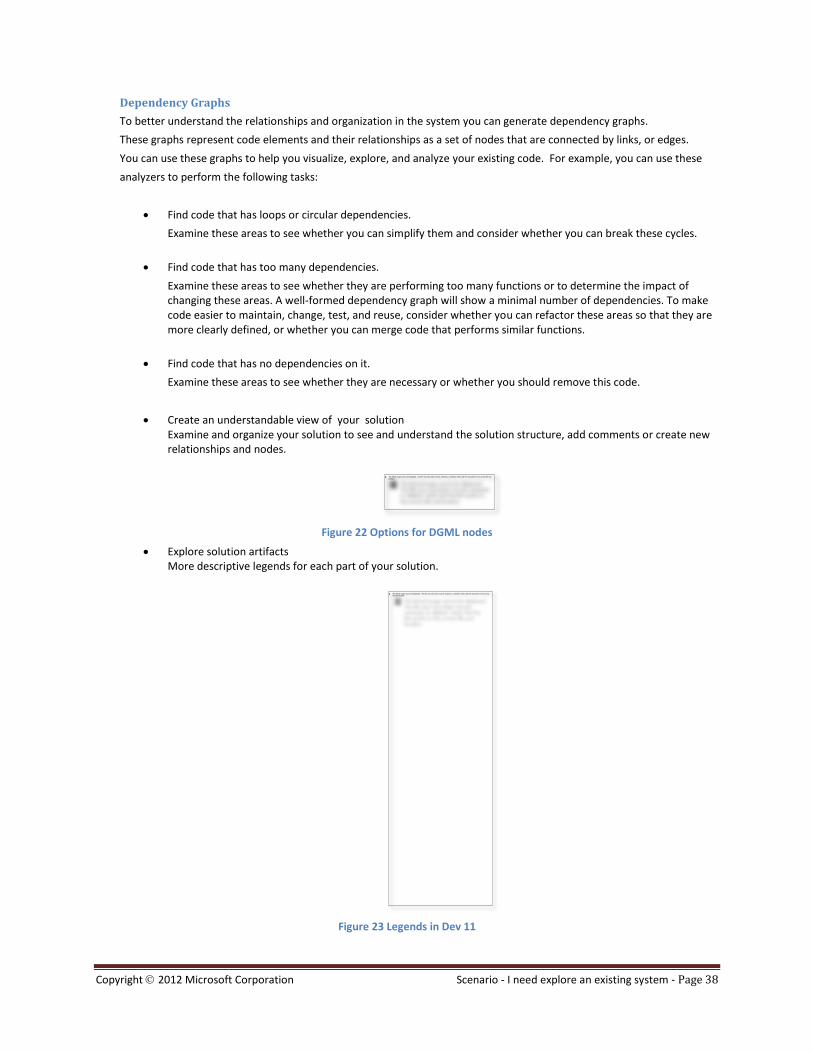
Create an understandable view of your solution Examine and organize your solution to see and understand the solution structure, add comments or create new relationships and nodes.
Figure 22 Options for DGML nodes
Explore solution artifacts More descriptive legends for each part of your solution.
Figure 23 Legends in Dev 11

Copyright 2012 Microsoft Corporation Scenario - I need explore an existing system - Page 39
OBSERVATION
The "generate for solution" option for generating DGML graphs is considered a best practice. It is very common to have multiple namespaces in an assembly and especially when using architectures based on the Patterns and Practices Application Architecture Guide 2.0, this option gives you a view that immediately shows any logical separations within the architecture.
However, this considered best practice is quite subjective – sometimes it’s the solution view that serves you better if you are trying to sort out the cross binary dependencies, especially where you are concerned about deployment.
Figure 24 - Dependency Graph For Solution
You can find a node by name, used for search through multiple levels of grouped nodes. Press CTRL+F to open the search box into the Dependency Graph.

Copyright 2012 Microsoft Corporation Scenario - I need explore an existing system - Page 40
Figure 25 Search Feature into Dependency Graphs
Figure 26 More mouse and keyboard gestures
Finally, at the left of the document, you also have a zoom control and a zoom-to-fit button if you prefer
From the Architecture menu you can generate dependency graphs For Solution or Include File. You can create dependency graphs for the following types of projects and files:

Copyright 2012 Microsoft Corporation Scenario - I need explore an existing system - Page 41
Visual C# .NET and Visual Basic .NET source code and compiled code, such as .NET assembly (.dll) files and executable (.exe) files
Visual C and Visual C++ source code, header (.h or #include) files, and binary files (managed or native)
OBSERVATION
When you open a solution that contains Visual C or Visual C++ projects, it might take some to update the IntelliSense database. During this time, the ability to generate dependency graphs for header (.h or #include) files, might be unavailable until the IntelliSense database finishes its updates. You can monitor the progress of these updates in the Visual Studio status bar.
For create dependency graphs for managed and native code you must use “For Solution” options, and for native code only use “For Include File”.
Figure 27 - Dependency Graph Options
Note that:
XMI import is part of the product
XMI export is not in the product but is available as source code in the Vs VmSdk
31 samples: XMI Exporter Extension for UML Designers
32
NOTE
It is not necessary to add a model project to the solution for all reverse engineering scenarios – both graphs and sequence diagrams do not require this – however it does provide a convenient location to store all models or pictures.
Discovering and preserving the logical architecture using layer diagrams
To better understand the logical architecture of an existing system we can create a Layer diagram from code artifacts. A layer diagram shows layers and their dependencies. You can create each layer to represent a group of types, code files, assemblies or other artifacts. You can name the layers so as to indicate their roles and functions.
When you have assigned code artifacts to the layers, you can either draw arrows to represent the dependencies that you want to allow, or you can have Visual Studio generate the current dependencies, and then edit them.
The layer diagrams can also be used to validate the architecture in future, ensuring that changes in the code do not inadvertently introduce new dependencies. See How to: Validate Code Against Layer Diagrams
33 and Layer Validation with
the VSTS 2010 CTP34
for more information.
31 http://code.msdn.microsoft.com/vsvmsdk 32 http://archive.msdn.microsoft.com/Project/Download/FileDownload.aspx?ProjectName=vsvmsdk&DownloadId=10140 33 http://msdn.microsoft.com/library/dd409395(v=vs.110).aspx

Copyright 2012 Microsoft Corporation Scenario - I need explore an existing system - Page 42
Figure 28 - Layer Diagram
Architecture Explorer
Another useful tool to explore existing code is the architecture explorer, which allows you to find code by navigating through the nodes or by using the filtering tool. You can also generate graph documents from selected nodes on architecture explorer or drag and drop nodes on to a layer diagram, using this approach as opposed to a standard graph to focus in on details instead of getting an overall picture.
Figure 29 – Architecture Explorer
Solution Explorer
Now in Visual Studio 2012 you can use Solution Explorer to find a specific type or member exploring the project structure or using the new search option and then find other items that have a specific kind of relationship with that type or member.
By default, Visual Studio displays items that have a containment relationship with the type or the member. However, you can choose a different relationship for the items that you want to include.
34 http://blogs.msdn.com/camerons/archive/2008/12/09/layer-validation-with-the-vsts-2010-ctp.aspx
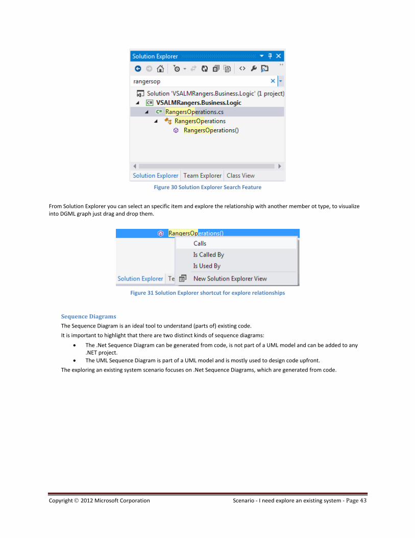
Copyright 2012 Microsoft Corporation Scenario - I need explore an existing system - Page 43
Figure 30 Solution Explorer Search Feature
From Solution Explorer you can select an specific item and explore the relationship with another member ot type, to visualize into DGML graph just drag and drop them.
Figure 31 Solution Explorer shortcut for explore relationships
Sequence Diagrams
The Sequence Diagram is an ideal tool to understand (parts of) existing code.
It is important to highlight that there are two distinct kinds of sequence diagrams:
The .Net Sequence Diagram can be generated from code, is not part of a UML model and can be added to any .NET project.
The UML Sequence Diagram is part of a UML model and is mostly used to design code upfront.
The exploring an existing system scenario focuses on .Net Sequence Diagrams, which are generated from code.

Copyright 2012 Microsoft Corporation Scenario - I need explore an existing system - Page 44
Figure 32 - Sequence Diagram
Class Diagrams
There are also two kinds of class diagrams:
The .NET class diagram is generated from code, can be added to any code project, and is not part of a UML model.
The UML class diagram is part of a UML model and is typically drawn manually to help describe logical aspects of the design. You can also generate UML class diagrams from code. By dragging classes from Architecture Explorer or Sultion Explorer onto the class diagram, you can decide which parts of the code you would like to visualize.
Using the Visual Studio you will also be able to consider code generation, which allows you to move not only from code to diagram, but from diagram to code as well.
Drawing a class diagram of the important parts of the system supports the understanding of large pieces of existing code. You do not need to create a class diagram for every part or class in the system, but instead should focus on key components in the system.
Class diagrams help you to communicate the key architectural aspects of an existing system.

Copyright 2012 Microsoft Corporation Scenario - I need explore an existing system - Page 45
Figure 33 - .NET Class Diagram
Create Other Diagrams
Finally, if you wish to implement a new feature to existing system you can use other UML diagrams. For more information on how to use the other UML diagrams visit Developing Models for Software Design
35 in the MSDN Library.
RECOMMENDATION
Refer to the “Visual Studio 2012 Architecture Guidance – Reverse Engineering HOL36
” for step-by-step walkthrough of this scenario.
35 http://msdn.microsoft.com/library/dd409436(v=vs.110).aspx 36 http://go.microsoft.com/fwlink/?LinkId=192799&clcid=0x409


Copyright 2012 Microsoft Corporation Scenario - I need to establish traceability - Page 47
Scenario - I need to establish traceability
OBSERVATION
We will be re-visiting this specific topic when the first wave of Architecture Feature Packs is available..
Requirements can be seen as being of several types in the traditional “SRS” (Software Requirements Specification) world. In the Agile world, requirements are typically captured in User Stories or Scenarios.
Irrespective of your approach to requirements capture, you can use models to help detail and define exactly what is supposed to be developed
37:
Use case diagram
Conceptual Class diagram
Activity Diagram
Sequence Diagram
Under this view, each of these diagrams can be seen as holding a piece of the total "requirement hologram", that is, the requirement is the sum of the information contained on all those pieces. The scope of this scenario, however, is how to establish the traceability of Requirements as work items to the diagrams and UML elements mentioned, and from those to other architectural artifacts.
Bridging Requirement work items to Use Case diagrams The out-of-the-box templates delivered with Visual Studio Team Foundation Server (TFS) do not contain a Use Case as a work item. That leaves the Use Case diagrams with no direct mapping to the Work Breakdown Structure (WBS) created with work items. There are a few options to implement traceability in this case:
1. Create a custom Use Case Work Item / Type of Work Item (in MSF CMMI) o This allows the creation of a Work Breakdown structure that neatly groups Scenarios/User Stories into Use
Cases; o Typed Links among high level (Use Case) and low level (Stories/Scenarios) are possible (for more
information on Typed Links, see Rangers Visual Studio Requirements Management Guidance38
or the product documentation;
o Queries, reports and project management metrics roll up to the Use Case level; o It however creates the extra burden to document and maintain in synch both the UML model and the work
item. Ideally the work item would just be a view of the UML model element. Another solution would be to implement a Custom Work Item Link Handler
39 that would synchronize it as needed.
2. Link to several User Story work items (or Requirements of type Scenario) as a replacement for a Use Case work item
o This allows the Use Case diagram to be used as an aggregator (in Agile terms, an “Epic”) of User Stories/Scenarios;
o There is no need to synchronize documentation among work item and Use Case as in the previous scenario; o However, queries, reports and project management metrics do not roll up to the Use Case level, leaving the
planning of Releases at the more granular level; o Also, Links are not Typed so the hierarchy of high level (Use Case) to low level (Stories/Scenarios) is implicit
so no additional information other than association is implied by the link. 3. Link from a Use Case Diagram to a development Task
o This is proposed the current Visual Studio 2012 documentation in the article Using Models within the Development Process
40;
o This is a good option for UML-driven projects where all requirements are kept in Team Foundation Server, and User Story/Scenario work items are not being used;
37 http://msdn.microsoft.com/library/dd409376(v=vs.110).aspx 38 http://vstfs2010rm.codeplex.com 39 http://msdn.microsoft.com/library/ee329485(v=vs.110).aspx 40 http://msdn.microsoft.com/library/dd409423(v=vs.110).aspx

Copyright 2012 Microsoft Corporation Scenario - I need to establish traceability - Page 48
o However it doesn’t allow for a good management of Releases, as naturally Use Cases tend to span iterations due to their intrinsic size (Writing Effective Use Cases
41, Advanced Use Case Modeling: Software Systems
42),
and this maps large portions of scope to the lower level of breakdown with Task work items. o Also, Links are not Typed so the hierarchy of high level (Use Case) to low level (Stories/Scenarios) is implicit.
4. Link to a document stored on an external system o This is the option that has the least amount of built in traceability but might be useful for existing projects
with extensive existing documentation.
Linking from a Use Case to a work item The mechanism for linking from a Use Case to a work item is captured on the next screens.
o From Use Case:
Figure 34 - Create Work Item from Use Case
o Select a work item query:
41 http://www.amazon.com/Writing-Effective-Cases-Alistair-Cockburn/dp/0201702258 42 http://www.amazon.com/Advanced-Use-Case-Modeling-Software/dp/0201615924

Copyright 2012 Microsoft Corporation Scenario - I need to establish traceability - Page 49
Figure 35 – Select work item query
o The updated Use Case properties will look like:
Figure 36 – Use Case Properties
o And the Use Case Diagram now shows an icon ( ) to the side of the Use Case showing that it is linked to a work item:

Copyright 2012 Microsoft Corporation Scenario - I need to establish traceability - Page 50
Figure 37 – Use Case Diagram and linked work item icon
Notice the current lack of Typed Links. To get bidirectional links between requirement work items and use cases, you must install TFS 11 (in Visual Studio 2010, you had to install the Visual Studio Feature Pack 2010). Without this extension, there is no link from the work item to back to the model element, which makes the enforcement of bi-directional traceability a difficult task.
For more details on how to link items see the documentation:
o How to: Link a Use Case to Documents and Diagrams43
o How to: Link Work Items to Model Elements
44
o How to Define a Work Item Link Handler45
43 http://msdn.microsoft.com/library/dd548710(vs= vs.100).aspx 44 http://msdn.microsoft.com/library/dd465152(vs= VS.100).aspx 45 http://msdn.microsoft.com/library/ee329485(vs= sv.100).aspx

Copyright 2012 Microsoft Corporation Scenario - I need to establish traceability - Page 51
Work Item to Model Element Back linking The Microsoft® Visual Studio® 2010 Visualization and Modeling Feature Pack introduced the ability to link from a Team Foundation Server Work Item to a model element. This feature is now baked into Visual Studio 2012.
Figure 38 – Linking from a Work Item to a Model Element
Creating Traceability reports The creation of Traceability reports is especially useful to verify that all requirements have been implemented, no matter how they were captured.
One issue in creating reports is that the UML models information is published to the project data warehouse solely as source code, with no other associated semantic units: that is, all the UML related information stays with the model. Therefore the standard report creation steps for TFS do not apply unless for each Use Case element we add a corresponding work item or a type of Requirement (in MSF CMMI). This will allow us to use the reports described in Ranger’s document “Visual Studio Team Foundation Server Requirements Management
46”.
OBSERVATION
This is a definite candidate for using extensibility and an area we will be reviewing in future versions of this guidance.
Using traceability reports for change impact analysis
The Rangers Visual Studio Requirements Management Guidance explains in detail how to create traceability reports. The main addition here is that the easiest way (in the RTM version) to implement Option 1 to enable traceability (topic “Create a custom Use Case Work Item / Type of Work Item (in MSF CMMI)” above). This provides the base to trace down into tasks and code starting with requirement work items. To create reports for Options 2 and 3 at this point it is possible to develop extensions to Visual Studio Team Architect to list the impacted work items.
46 http://vstfs2010rm.codeplex.com/


Copyright 2012 Microsoft Corporation Scenario – I need to validate a system architecture - Page 53
Scenario – I need to validate a system architecture
Figure 39 - Validation of a system architecture
Testers can use requirements models to create test cases and test plans for the validation of the application. They can also add value, by raising the quality level of the requirements and documentation with the ‘test’ expertise. In this way, tests provide a strong connection between the models and the implantation code.
This validation scenario can be divided into three separate, loosely connected sub-scenarios:
1. Validating the requirements and architectural model. Testers can perform a quality check of the modeling effort and can file bugs about the documentation, requirements, corresponding architecture and design.
2. Designing tests based on the models. Testers can extract information from the models and can store references to these models for maintenance. The implementation tests are built upon the model validations developed in the first sub-scenario.
3. Validation of the Design against Key Design Principles.
Validating the UML Models
Considerations
Each phase of the development process has its own test goals and depth of test coverage. The depth particularly depends upon the risks: higher probability of damage requires better test coverage.
Test goals are especially aimed at discovering errors that can be found in each phase (“as early as possible”).
During unit testing the internal logic of the unit is tested.
The system integration test needs to show that units “understand” each other.
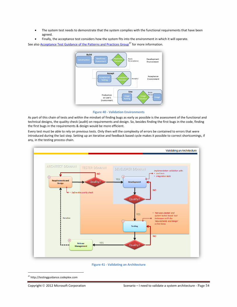
Copyright 2012 Microsoft Corporation Scenario – I need to validate a system architecture - Page 54
The system test needs to demonstrate that the system complies with the functional requirements that have been agreed.
Finally, the acceptance test considers how the system fits into the environment in which it will operate.
See also Acceptance Test Guidance of the Patterns and Practices Group47
for more information.
Figure 40 - Validation Environments
As part of this chain of tests and within the mindset of finding bugs as early as possible is the assessment of the functional and technical designs, the quality check (audit) on requirements and design. So, besides finding the first bugs in the code, finding the first bugs in the requirements & design would be more efficient.
Every test must be able to rely on previous tests. Only then will the complexity of errors be contained to errors that were introduced during the last step. Setting up an iterative and feedback based cycle makes it possible to correct shortcomings, if any, in the testing process chain.
Figure 41 - Validating an Architecture
47 http://testingguidance.codeplex.com

Copyright 2012 Microsoft Corporation Scenario – I need to validate a system architecture - Page 55
To validate the quality of the modeling effort, corresponding documentation and requirements, you should target three sets of questions: complete, correct, and consistent; covering three areas: syntax, functionality, and traceability.
See Use Cases and Testing48 by Lee Copeland for more information.
Record your findings in Bug work items in TFS.
“The business facing tests that drive development are the system acceptance tests (also known as customer tests). These tests elaborate on the requirements and the very act of writing these tests can expose missing or ambiguous requirements. When we (Product Owner, often together with someone from the Product Development Team) prepare these tests before development starts, we can be sure that the Product Development Team understands what they need to build. This is known as Acceptance Test-Driven Development.”
49
Please refer to Developing Tests from a Model
50 for more information in MSDN Library.
Walkthrough
In this scenario, a good starting point for testing is the use cases, which describe the various actors and how they use the system to accomplish specific goals. The use case model, which is represented in Visual Studio 2012 in the UML Model Explorer, provides a clear overview of all the actors and use cases in the project. This is the perfect place to start the validation exercise.
48 http://www.stickyminds.com/sitewide.asp?Function=edetail&ObjectType=ART&ObjectId=3428#authorbio 49 http://testingguidance.codeplex.com 50 ttp://msdn.microsoft.com/library/dd409381.aspx

Copyright 2012 Microsoft Corporation Scenario – I need to validate a system architecture - Page 56
Figure 42 - UML Model Explorer
There are several areas of use cases that you can validate as a tester. For example you can focus on the syntax of use cases, the functionality that is described in the use cases, or the traceability of the use cases. See the Appendix on page 72 for a validation checklist.
Within these areas you can focus on different aspects such as completeness, correctness, and consistency. You can either validate just the model, or you can expand your focus to encompass the corresponding documents on the project portal. For example the use case diagram in VS2010 has a model element with the capabilities to link any kind of other artefact. Checking these documents against the model gives a great overview of the state of the design.
An example of inconsistency between these artefacts could be for example; that a document linked to a use case talks about five activities that need to be executed to place an order. But in an activity diagram linked to the same use case, only two activities are drawn. File a bug for these kinds of problems.
As an example of validating the syntax of use cases, you could verify that the name of each use case is the primary actor’s goal expressed as an active phrase.

Copyright 2012 Microsoft Corporation Scenario – I need to validate a system architecture - Page 57
Figure 43 - Validation of Use Case Diagram
In the above use case diagram the name of the diagram is unclear. The use case name should describe the primary actor's goal expressed as an active verb phrase. As we can see, this clearly isn’t the case and therefore the tester should raise a bug against this use case. In Visual Studio 2010 we can do this by following these steps:
Select Use Case
Right click
Select create new work item, bug
Fill in the details.
Figure 44 - Create Work Item, linked to Use Case
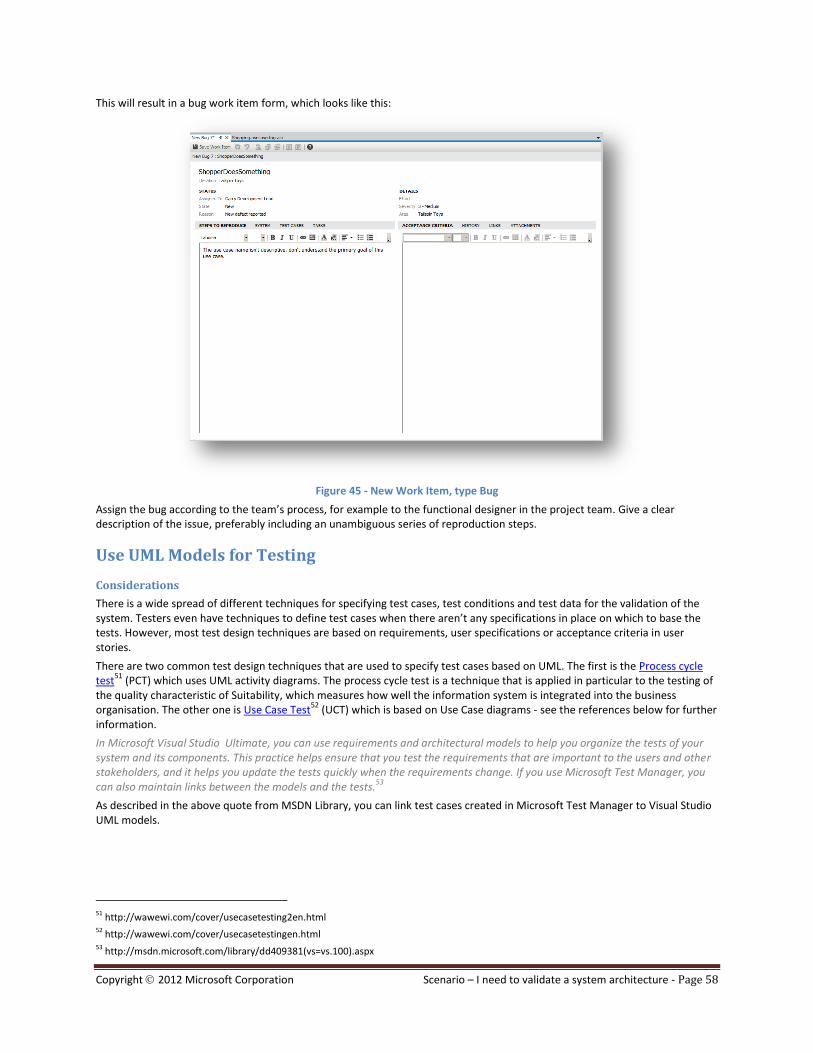
Copyright 2012 Microsoft Corporation Scenario – I need to validate a system architecture - Page 58
This will result in a bug work item form, which looks like this:
Figure 45 - New Work Item, type Bug
Assign the bug according to the team’s process, for example to the functional designer in the project team. Give a clear description of the issue, preferably including an unambiguous series of reproduction steps.
Use UML Models for Testing
Considerations
There is a wide spread of different techniques for specifying test cases, test conditions and test data for the validation of the system. Testers even have techniques to define test cases when there aren’t any specifications in place on which to base the tests. However, most test design techniques are based on requirements, user specifications or acceptance criteria in user stories.
There are two common test design techniques that are used to specify test cases based on UML. The first is the Process cycle test
51 (PCT) which uses UML activity diagrams. The process cycle test is a technique that is applied in particular to the testing of
the quality characteristic of Suitability, which measures how well the information system is integrated into the business organisation. The other one is Use Case Test
52 (UCT) which is based on Use Case diagrams - see the references below for further
information.
In Microsoft Visual Studio Ultimate, you can use requirements and architectural models to help you organize the tests of your system and its components. This practice helps ensure that you test the requirements that are important to the users and other stakeholders, and it helps you update the tests quickly when the requirements change. If you use Microsoft Test Manager, you can also maintain links between the models and the tests.
53
As described in the above quote from MSDN Library, you can link test cases created in Microsoft Test Manager to Visual Studio UML models.
51 http://wawewi.com/cover/usecasetesting2en.html 52 http://wawewi.com/cover/usecasetestingen.html 53 http://msdn.microsoft.com/library/dd409381(vs=vs.100).aspx

Copyright 2012 Microsoft Corporation Scenario – I need to validate a system architecture - Page 59
Validation of Key Design Principles and Considerations
Considerations
The validations that we have discussed so far are all relevant to and executed by the tester, but there are other domains where validations take place.
One very good starting point for architectural validations would the Microsoft P&P Application Architecture Guide 2.0. This guide includes checklists that identify some basic principles and best practices of a solid architectural design.
Some of the ‘rules’ that we can find in this guide are:
Separation of concerns
Single Responsibility principle
Principle of Least Knowledge
Don’t repeat yourself (DRY)
Minimize upfront design
Keep design patterns consistent within each layer.
Do not duplicate functionality within an application.
Prefer composition to inheritance
Establish a coding style and naming convention for development
Use abstraction to implement loose coupling between layers.
Be explicit about how layers communicate with each other
Do not mix different types of components in the same logical layer
Keep crosscutting code abstracted from the application business logic as far as possible
Layer Validation
Although not all of the above mentioned architectural validations can be validated against the layer diagram (or UML diagram in Visual Studio) there are numerous architectural validations that can.
Manual System Design Validation
A practice in validation of the implementation between the functional design and technical design is to ‘replay’ usage scenarios. For example the scenario ‘logon on to a web store, add items to a basket, do a credit check and payment’, has a flow through the system. The scenario is designed in the use case and activity diagrams and the design diagrams such as the component diagram.

Copyright 2012 Microsoft Corporation Scenario – I need to validate a system architecture - Page 60
Figure 46 – Component Diagram
When we have both of these designs in place, functional and design, we can replay the activities over the interfaces of the component diagram. This gives a way to validate the above mentioned design principles. Visualizing this flow through the interfaces of the components in a sequence diagram gives us a great overview for validation and communication. With the component diagram in Visual Studio you can create lifelines from the components:
Figure 47 – Sequence Diagram
Looking at Figure 48 - Manual Design Validation:
The scenarios used can be found in the use case diagrams , which describe the actions that take place on/in the system.
An activity diagram can be used to visualize the scenarios, which can be based on the use case diagram as a kind of use case realization. Testers use activity diagrams to design test cases using test design techniques (see page 58) to create the right amount and type for these scenarios
54. The same scenarios can be used to validate our component
design; which closes the overall loop.
The component diagram is a static view of your system, whereas the sequence diagram is dynamic. The sequence diagram visualizes the flow and the sequence of actions that occur in the system.
Sequence diagrams can be used to validate the system and the component design, by taking a scenario, a
requirement scenario, and creating a sequence of actions in a sequence diagram .
By doing this you create a kind of simulated behavior of the component structure, which you can check for correctness and consistency.
54 http://robkuijt.nl/index.php?entry=entry080423-135750
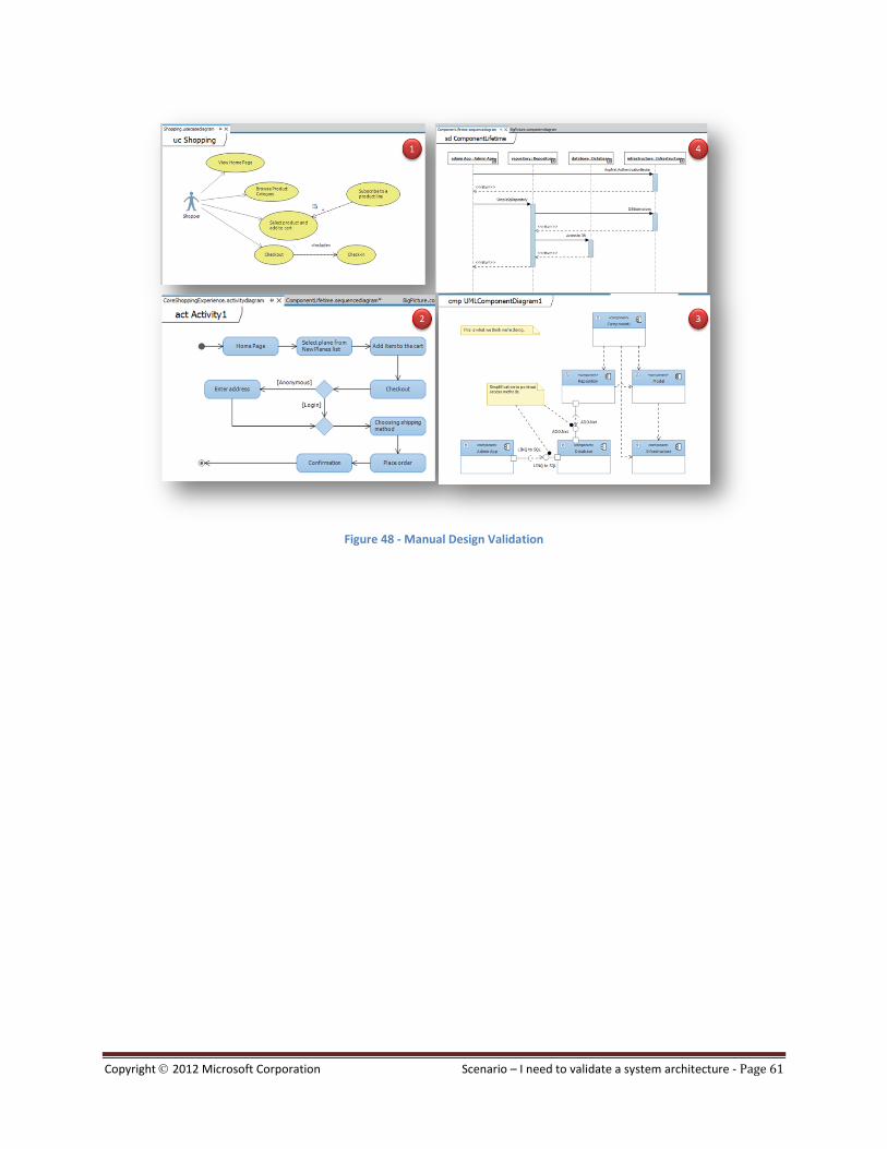
Copyright 2012 Microsoft Corporation Scenario – I need to validate a system architecture - Page 61
Figure 48 - Manual Design Validation

Copyright 2012 Microsoft Corporation Scenario – I need to validate a system architecture - Page 62
Scenario - I need to customize DGML graphs
GOAL
This scenario is focused for architects and developers for understood DGML concepts and how to customize DGML Graphs to
support different kinds of scenarios and how this customization can be made using Visual Studio 2012.
Overview
DGML (Directed Graph Markup Language) Graphs are used to show the relationships between elements and how they are related, used by Visual Studio 2012 Architecture to render graphs, but DGML graphs must be used in other scenarios, for example represent SharePoint site structure. DGML graphs are a powerful tool to express different kinds of information into a graph based on nodes, containers and relationships.
Since Visual Studio 2010, a suite of tools for Software Developers including support for generating DGML graphs from relationships in code and for viewing any DGML document generated by any other tool.
Often it is used as a way to understand large code bases with dependency diagrams but could be used to create a lot of definitions about an application.
A DGML file is basically composed by nodes, links, categories, properties and styles as illustrated on Figure 49: DGML Basic Elements. The complete XSD schema for DGML is available at http://schemas.microsoft.com/vs/2009/dgml/. DGML not only allows describing nodes and links in a graph, but also annotating those nodes and links with any user defined property and/or category.
Figure 49: DGML Basic Elements

Copyright 2012 Microsoft Corporation Scenario – I need to validate a system architecture - Page 63
Graph Elements Definition
The xml representation of a DGML file is illustrated on Figure 50: DGML Basic Structure.
Figure 50: DGML Basic Structure
Nodes: The list of graph elements are represented in nodes, each element is a Node.
Links: the relationships between nodes are represented as links.
NOTE
When you reference an undefined node in a <Link/> element, the graph creates a <Node/> element automatically.
Categories: This element defines a Category attribute, which is used to identify elements that share this attribute. A Category attribute can be used to organize graph elements, or define additional metadata. Categories also provide some basic styling behavior that controls the appearance of nodes and links when they are displayed on a graph
Properties: This element contains the list of <Property/> elements. Each Property attribute you can use to assign a value to any DGML element or attribute, including categories and other properties.
Styles: With Styles you can apply conditional styles for example to specific category. A conditional style can apply UI settings to a matching set of nodes or links based on a conditional expression.
NOTE
You can apply custom styles to the following items:
Single nodes and links
Groups of nodes and links
Groups of nodes and links based on certain conditions.
<?xml version="1.0" encoding="utf-8"?> <DirectedGraph xmlns="http://schemas.microsoft.com/vs/2009/dgml"> <Nodes> </Nodes> <Links> </Links> <Categories> </Categories> <Properties> </Properties> <Styles> </Styles>
</DirectedGraph>

Copyright 2012 Microsoft Corporation Scenario – I need to validate a system architecture - Page 64
DGML Generation and Customization Workflow
DGML graphs has various applications for example generate DGML graphs from relationships in code from Architecture menu, architecture explorer, solution explorer, also you can create a blank DGML file from New menu, and then represent other kinds of information into graphs.
Also you can use other tools, your own c# code or T4 templates for to additional sources like xml, flat files or other sources and generate a graph, in this process you can write code to apply conditional styles to your graph, for example, you may have the needed to reverse engineer a SharePoint 2007 Farm to prepare for an upgrade to 2010, you can write your own code to represent the SharePoint Structure into DGML Graph. To read more about this example read this blog post.
Once DGML file is generated you can continue customizing your graph through Visual Studio designers or directly in the DGML source, for more information refer to DGML Manual Customization included as part of this scenario.
Figure 51: DGML Generation and Customization Workflow
RECOMMENDATION

Copyright 2012 Microsoft Corporation Scenario – I need to validate a system architecture - Page 65
Refer to Step 4 of the Visual Studio 2012 Architecture Guide - Customize DGML – HOL.docx, and learn how to use T4 template
for generate a Graph from xml file.
DGML Manual Customization
Once you understand each part of a DGML file, maybe you wish to highlight areas of interest; you can select and filter nodes, apply predefined styles to nodes and links, and organize nodes into groups. You can customize the graph even further by editing the graph's Directed Graph Markup Language (DGML) file.
Please refer to How to: Edit and Customize Graph Documents where you can find topics related with DGML manual edit and customization using designers and xml source, the Figure 52: Edit and Customize Dependency Graphs on MSDN show you the topics covered on MSDN article.
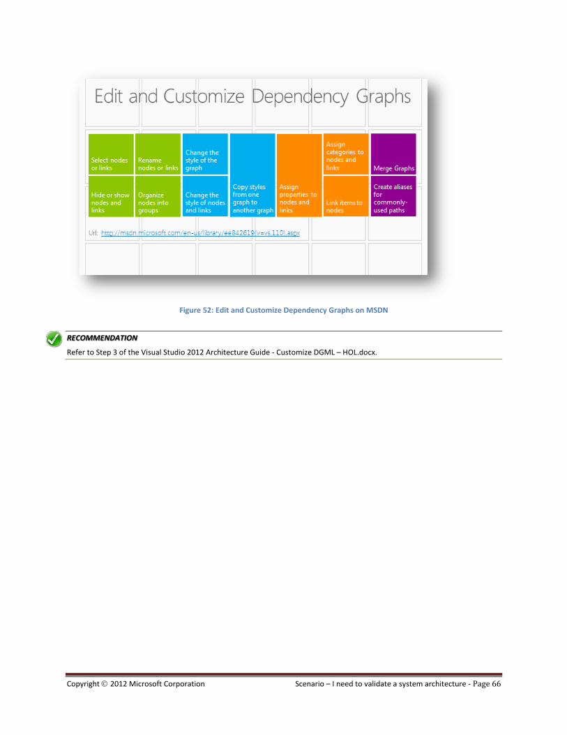
Copyright 2012 Microsoft Corporation Scenario – I need to validate a system architecture - Page 66
Figure 52: Edit and Customize Dependency Graphs on MSDN
RECOMMENDATION
Refer to Step 3 of the Visual Studio 2012 Architecture Guide - Customize DGML – HOL.docx.
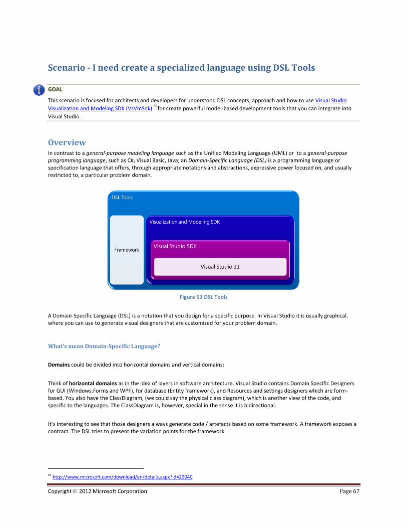
Copyright 2012 Microsoft Corporation Page 67
Scenario - I need create a specialized language using DSL Tools
GOAL
This scenario is focused for architects and developers for understood DSL concepts, approach and how to use Visual Studio
Visualization and Modeling SDK (VsVmSdk) 55
for create powerful model-based development tools that you can integrate into
Visual Studio.
Overview In contrast to a general-purpose modeling language such as the Unified Modeling Language (UML) or to a general-purpose programming language, such as C#, Visual Basic, Java; an Domain-Specific Language (DSL) is a programming language or specification language that offers, through appropriate notations and abstractions, expressive power focused on, and usually restricted to, a particular problem domain.
Figure 53 DSL Tools
A Domain-Specific Language (DSL) is a notation that you design for a specific purpose. In Visual Studio it is usually graphical, where you can use to generate visual designers that are customized for your problem domain.
What’s mean Domain-Specific Language?
Domains could be divided into horizontal domains and vertical domains:
Think of horizontal domains as in the idea of layers in software architecture. Visual Studio contains Domain Specific Designers for GUI (Windows.Forms and WPF), for database (Entity framework), and Resources and settings designers which are form-based. You also have the ClassDiagram, (we could say the physical class diagram), which is another view of the code, and specific to the languages. The ClassDiagram is, however, special in the sense it is bidirectional.
It’s interesting to see that those designers always generate code / artefacts based on some framework. A framework exposes a contract. The DSL tries to present the variation points for the framework.
55 http://www.microsoft.com/download/en/details.aspx?id=29040
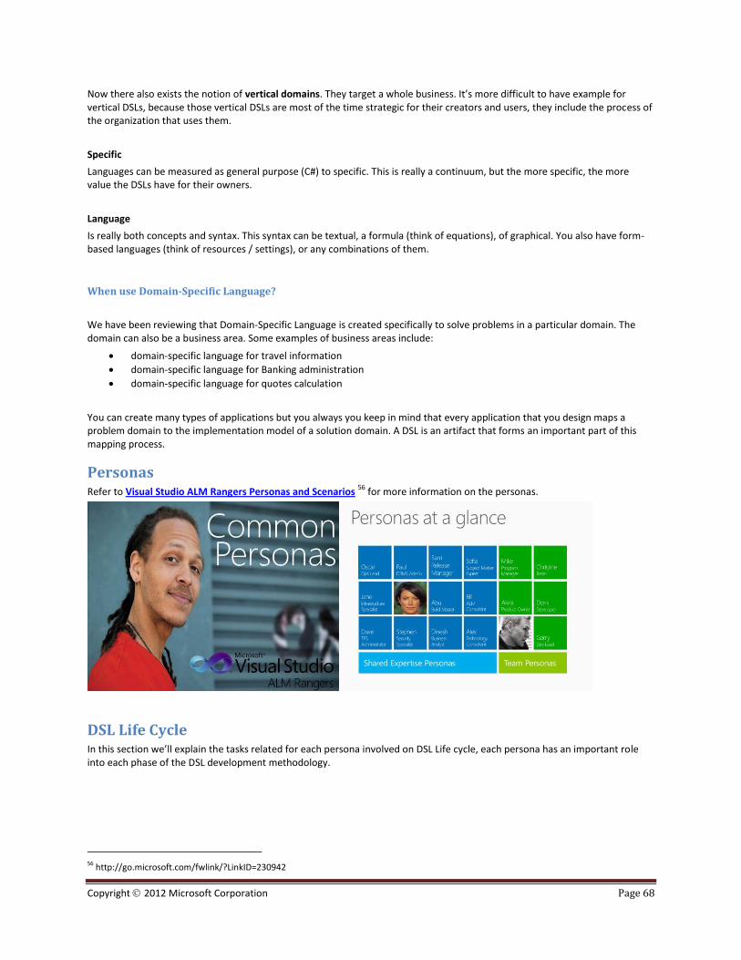
Copyright 2012 Microsoft Corporation Page 68
Now there also exists the notion of vertical domains. They target a whole business. It’s more difficult to have example for vertical DSLs, because those vertical DSLs are most of the time strategic for their creators and users, they include the process of the organization that uses them.
Specific
Languages can be measured as general purpose (C#) to specific. This is really a continuum, but the more specific, the more value the DSLs have for their owners.
Language
Is really both concepts and syntax. This syntax can be textual, a formula (think of equations), of graphical. You also have form-based languages (think of resources / settings), or any combinations of them.
When use Domain-Specific Language?
We have been reviewing that Domain-Specific Language is created specifically to solve problems in a particular domain. The domain can also be a business area. Some examples of business areas include:
domain-specific language for travel information
domain-specific language for Banking administration
domain-specific language for quotes calculation
You can create many types of applications but you always you keep in mind that every application that you design maps a problem domain to the implementation model of a solution domain. A DSL is an artifact that forms an important part of this mapping process.
Personas Refer to Visual Studio ALM Rangers Personas and Scenarios
56 for more information on the personas.
DSL Life Cycle In this section we’ll explain the tasks related for each persona involved on DSL Life cycle, each persona has an important role into each phase of the DSL development methodology.
56 http://go.microsoft.com/fwlink/?LinkID=230942
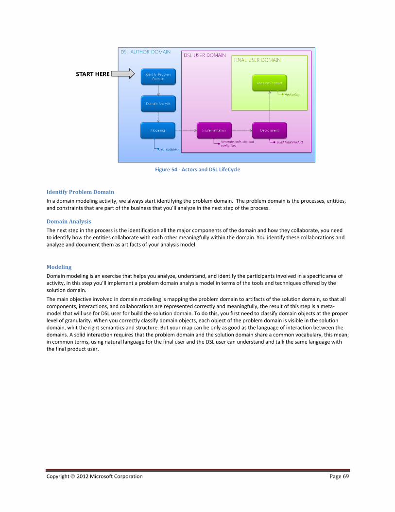
Copyright 2012 Microsoft Corporation Page 69
Figure 54 - Actors and DSL LifeCycle
Identify Problem Domain
In a domain modeling activity, we always start identifying the problem domain. The problem domain is the processes, entities, and constraints that are part of the business that you’ll analyze in the next step of the process.
Domain Analysis
The next step in the process is the identification all the major components of the domain and how they collaborate, you need to identify how the entities collaborate with each other meaningfully within the domain. You identify these collaborations and analyze and document them as artifacts of your analysis model
Modeling
Domain modeling is an exercise that helps you analyze, understand, and identify the participants involved in a specific area of activity, in this step you’ll implement a problem domain analysis model in terms of the tools and techniques offered by the solution domain.
The main objective involved in domain modeling is mapping the problem domain to artifacts of the solution domain, so that all components, interactions, and collaborations are represented correctly and meaningfully, the result of this step is a meta-model that will use for DSL user for build the solution domain. To do this, you first need to classify domain objects at the proper level of granularity. When you correctly classify domain objects, each object of the problem domain is visible in the solution domain, whit the right semantics and structure. But your map can be only as good as the language of interaction between the domains. A solid interaction requires that the problem domain and the solution domain share a common vocabulary, this mean; in common terms, using natural language for the final user and the DSL user can understand and talk the same language with the final product user.

Copyright 2012 Microsoft Corporation Page 70
Figure 55: Modeling DSL definition using VsVmSdk
RECOMMENDATION
A good abstraction is essential to a well-designed DSL implementation, Visual Studio Visualization and Modeling SDK
(VsVmSdk) include designers for help you to create the model to represent concepts in your business area .
Implementation
In the implementation phase the DSL users uses the dsl definition created by the DSL Author for create the product, in this step the DSL user generates code, docs and configuration files for the target Framework. The DSL definition is full supported integrated with Visual Studio IDE enabling to the DSL User write custom and extensible code, this code could include model validations. In most common development processes this step could include test activities, where the DSL user include a test project for unit testing of each part of the generated artifacts.
Deployment
This step consist in the build the artifacts generated in the previous step, now in Build service of Visual Studio Team Foundation Server you could include the definition for build the DSL artifacts generated from a meta-model.
Uses the Product
In this step the final product is ready for install to the target framework and ready for be used for the final product user.
RECOMMENDATION
We recommend follow the DSL Tools hol where we use a simple sample cross all process explained in this scenario.

Copyright 2012 Microsoft Corporation Page 71

Copyright 2012 Microsoft Corporation Page 72
Appendix
UML Model Checklists The following checklists are useful guides when validating use cases, sequence and class diagrams as part of the Validation Scenario. The checklists have been sourced from Use Cases and Testing Parts 1,2 and 3
57 and expanded in places.
Use Cases / activity diagram
NOTE
Use with the Validation Scenario. See page 53 for more information.
Syntax Testing
Complete:
Are all use case definition fields filled in? Do we really know what the words mean?
Are all of the steps required to implement the use case included?
Are all of the ways that things could go right identified and handled properly? Have all combinations been considered?
Are all of the ways that things could go wrong identified and handled properly? Have all combinations been considered?
If you have a class diagram of business concepts:
Is there a use case that describes how each class is instantiated?
Is there a use case that describes how each association is created and destroyed, and how the value of each attribute is set?
If you describe the goals or post-conditions of each use case, do all the business entities and relationships in the descriptions appear in the business concept class diagram?
Correct:
Is the use case name the primary actor's goal expressed as an active verb phrase?
Is the use case described at the appropriate black box/white box level?
Are the preconditions mandatory? Can they be guaranteed by the system?
Does the failed end condition protect the interests of all the stakeholders?
Does the success end condition satisfy the interests of all the stakeholders?
Does the main success scenario run from the trigger to the delivery of the success end condition?
Is the sequence of action steps correct?
Is each step stated in the present tense with an active verb as a goal that moves the process forward?
Is it clear where and why alternate scenarios depart from the main scenario?
Are design decisions (GUI, Database, …) omitted from the use case?
Are the use case "generalization," "include," and "extend" relationships used to their fullest extent but used correctly?
Consistent:
Can the system actually deliver the specified goals?
If you have described constraints on the business concept class diagram:
Are the goals of the use cases consistent with these constraints?
57 http://www.stickyminds.com/sitewide.asp?Function=edetail&ObjectType=ART&ObjectId=3428#authorbio
Copyright 2012 Microsoft Corporation Page 73
Domain Expert Testing
Complete:
Are all actors identified? Can you identify a specific person who will play the role of each actor?
Is this everything that needs to be developed?
Are all external system trigger conditions handled?
Have all the words that suggest incompleteness ("some," "etc."…) been removed?
Correct:
Is this what you really want? Is this all you really want? Is this more than you really want?
Consistent:
When we build this system according to these use cases, will you be able to determine that we have succeeded?
Can the system described actually be built?
Traceability Testing
Complete:
Do the use cases form a story that unfolds from highest to lowest levels?
Is there a context-setting, highest-level use case at the outermost design scope for each primary actor?
Correct:
Are all the system's functional requirements reflected in the use cases?
Are all the information sources listed?
Consistent:
Do the use cases define all the functionality within the scope of the system and nothing outside the scope?
Can we trace each use case back to its requirement(s)?
Can we trace each use case forward to its class, sequence, and state-transition diagrams?

Copyright 2012 Microsoft Corporation Page 74
Sequence Diagram
NOTE
Use with the Validation Scenario. See page 53 for more information.
Syntax Testing
Complete:
Does each object required for the interaction appear on the diagram?
Correct:
Have all objects not required in the interaction been removed from the diagram?
Does each object’s lifeline begin and end at the proper time?
Is each object’s activation described properly?
If the object’s lifetime terminates, is it indicated with an X?
Is each message well named with a strong verb?
Are proper parameters included for each message?
Are conditional branches drawn properly?
Consistent:
Do conditionals cover all of the cases?
Have any overlaps of conditionals been removed?
Domain Expert Testing
Complete:
Are all the ways that things could go right identified and handled properly?
Are all the ways that things could go wrong identified and handled properly?
Does the main success scenario run from the trigger to the delivery of the success end condition?
Correct:
Does the sequence diagram show each step that must be executed to implement the function?
Can each step actually be implemented?
Traceability Testing
Consistent:
Is each use case represented by at least one sequence diagram?
Does each actor appear on at least one sequence diagram?

Copyright 2012 Microsoft Corporation Page 75
Class Diagram
NOTE
Use with the Validation Scenario. See page 53 for more information.
Syntax Testing
Complete:
Does each class define attributes, methods, relationships, and cardinality?
Is each association well named?
Is each association’s and aggregation’s cardinality correct?
Correct:
Are all attributes private?
Are all parameters explicit rather than being embedded in method names?
Do all subclasses implement the "is-a-kind-of" relationship properly?
Are all object states represented explicitly using states and transitions rather than as subclasses?
In inheritance structures, are all attributes and methods pushed as high in the inheritance structure as is proper?
Are all polymorphic methods within related subclasses identically named?
Does each association reflect a relationship that exists over the lives of the related objects?
Consistent:
Are each 0..* and 1..* relationships implemented with containers/collectors?
Are each association’s cardinalities consistent (instantaneous vs. over-time)?
Domain Expert Testing
Correct:
Is each class named with a strong noun?
Have all redundant, irrelevant, or vague classes been removed from the diagram?
Is each attribute defined within the proper class? Is it of the correct type?
Is the visibility of each attribute correct?
Are the default values of each attribute specified correctly?
Is each attribute essential rather than computable from others?
Is each method in the correct class?
Are all method names strong verbs?
Does each method take the correct input parameters and return the correct output parameter?
Is the visibility of each method correct?
Does each method implement one and only one behavior?
Is the public interface free from unnecessary methods?
Consistent:
Is the class diagram drawn at the appropriate level: conceptual, specification, or implementation?
Traceability Testing
Consistent:
Is each object on the sequence diagram represented by a class on the class diagram?
Is every message on the sequence diagram reflected as a method in the appropriate class?