VISTA-128BP/VISTA-250BP Programming Formlibrary.ademconet.com/MWT/fs2/7/1508.pdf– 5 –...
7
– 5 – VISTA-128BP/VISTA-250BP Programming Form Some fields are programmed for each partition (shown as shaded fields). If you are programming a multiple-partition system, see the Partition-Specific Fields section for programming these fields. Standard default (*97) values are shown in brackets [ ]; otherwise, default = 0. *00 INSTALLER CODE | | | Enter 4 digits, 0-9 [4140] *04 ENABLE RANDOM TIMERS 1 2 3 4 5 6 7 8 Enter 1 to make available the randomizing of pre-programmed time driven events for each partition. [0=disable]. *05 SYSTEM EVENTS NOTIFY [0] 1=yes, (messages sent via the RS232 port). 0=no, (no messages sent). *06 QUICK EXIT [1] 1=enable; 0=disable Must be 0 for UL installations. *09 ENTRY DELAY #1 [02] | 00, 02-15 times 15 seconds Maximum "03" for UL. SIA Guidelines: The entry delay time and Burg Alarm Comm Delay (field *88) combined cannot exceed 1 minute. *10 EXIT DELAY #1 [04] | 00, 03-15 times 15 seconds Maximum "04" for UL installations. SIA Guidelines: Minimum 45 seconds “03”. *11 ENTRY DELAY #2 [02] | 00, 02-15 times 15 seconds (must be longer than Entry Delay #1). Maximum "03" for UL installations. SIA Guidelines: The entry delay time and Burg Alarm Comm Delay (field *88) combined cannot exceed 1 minute. *12 EXIT DELAY #2 [08] | 00, 03-15 times 15 seconds (must be longer than Exit Delay #1). Maximum "04" for UL installations. SIA Guidelines: Minimum 45 seconds “03”. *13 ALARM SOUNDER DURATION [04] | 01-15 times 2 minutes. Must be minimum 16 minutes for UL installations. SIA Guidelines: Must be minimum 6 minutes. *14 BURGLARY OR RS232 INPUT [0] Enter 1 to set terminal 23 as a RS232 input to enable system to receive serial data (75 baud) via terminal 23. Enter 0 to enable terminal 23 as burglary input for zone 9. *15 KEYSWITCH ASSIGNMENT [0] Enter partition in which keyswitch used, 1-8; 0=disable *16 CONFIRMATION OF ARMING DING [0] 1=enable; 0=disable. Must be "1" for UL Installations. *17 AC LOSS KEYPAD SOUNDING [0] 1=yes; 0=no *19 RANDOMIZE AC LOSS REPORT [0] 1=10-40 min; 0=normal report (about 2 min. after AC loss). *20 VIP MODULE PHONE CODE | | Enter 01 - 09 for the first digit; enter [00], [11] 11 for “*” or 12 for “#” for the second digit. Must be set to "0" for UL installations. *21 PREVENT FIRE TIMEOUT [0] 1=No timeout; 0=Timeout. *22 KEYPAD PANIC ENABLES [001] 1=enable; 0=disable 995 996 999 *23 MULTIPLE ALARMS [1] 1=yes; 0=no *24 IGNORE EXPANSION ZONE TAMPER [0] 1=Ignore; 0=Enable tamper for RF and RPMs. Must be "0" for UL installations if using these devices. *25 BURG.TRIGGER FOR RESPONSE TYPE 8 [1] 1=enable; 0=disable *26 INTELLIGENT TEST REPORTING [0] 1=yes (no report sent if any other report was recently sent); 0=no (send report at programmed interval, field *27) Must be 0 for UL installations. *27 TEST REPORT INTERVAL [0024] | | | Enter interval in hours, 0001-9999; 0000=no report; Max. 0024 for UL installations. *28 POWER UP IN PREVIOUS STATE [1] 1=yes; 0=no; "1" for UL installations. *29 QUICK ARM [1] 1=yes; 0=no *30 TOUCHTONE OR ROTARY DIAL [0] 1=TouchTone; 0=rotary *31 PABX ACCESS CODE | | | | 00-09; B-F (11-15) *32 PRIM. SUBS. ACCT # | | | | Enter 00-09; B-F (11-15) [15 15 15 15] *33 PRIMARY PHONE NUMBER Enter 0-9 for each digit. Enter #11 for *, #12 for #, #13 for 2 second pause *34 SECONDARY PHONE NUMBER Enter 0-9 for each digit. Enter #11 for *, #12 for #, #13 for 2 second pause
Transcript of VISTA-128BP/VISTA-250BP Programming Formlibrary.ademconet.com/MWT/fs2/7/1508.pdf– 5 –...

– 5 –
VISTA-128BP/VISTA-250BP Programming Form Some fields are programmed for each partition (shown as shaded fields). If you are programming a multiple-partition system, see the Partition-Specific Fields section for programming these fields. Standard default (*97) values are shown in brackets [ ]; otherwise, default = 0.
*00 INSTALLER CODE | | | Enter 4 digits, 0-9 [4140]
*04 ENABLE RANDOM TIMERS
1
2
3
4
5
6
7
8
Enter 1 to make available the randomizing of pre-programmed time driven events for each partition. [0=disable].
*05 SYSTEM EVENTS NOTIFY [0] 1=yes, (messages sent via the RS232 port). 0=no, (no messages sent).
*06 QUICK EXIT [1] 1=enable; 0=disable Must be 0 for UL installations.
*09 ENTRY DELAY #1 [02] | 00, 02-15 times 15 seconds Maximum "03" for UL. SIA Guidelines: The entry delay time and Burg Alarm Comm
Delay (field *88) combined cannot exceed 1 minute.
*10 EXIT DELAY #1 [04] | 00, 03-15 times 15 seconds Maximum "04" for UL installations. SIA Guidelines: Minimum 45 seconds “03”.
*11 ENTRY DELAY #2 [02] | 00, 02-15 times 15 seconds (must be longer than Entry Delay
#1). Maximum "03" for UL installations. SIA Guidelines: The entry delay time and Burg Alarm Comm
Delay (field *88) combined cannot exceed 1 minute.
*12 EXIT DELAY #2 [08] | 00, 03-15 times 15 seconds (must be longer than Exit Delay
#1). Maximum "04" for UL installations. SIA Guidelines: Minimum 45 seconds “03”.
*13 ALARM SOUNDER DURATION [04] | 01-15 times 2 minutes. Must be minimum 16 minutes for UL
installations. SIA Guidelines: Must be minimum 6 minutes.
*14 BURGLARY OR RS232 INPUT [0] Enter 1 to set terminal 23 as a RS232 input to enable system
to receive serial data (75 baud) via terminal 23. Enter 0 to enable terminal 23 as burglary input for zone 9.
*15 KEYSWITCH ASSIGNMENT [0] Enter partition in which keyswitch used, 1-8; 0=disable
*16 CONFIRMATION OF ARMING DING [0] 1=enable; 0=disable. Must be "1" for UL Installations.
*17 AC LOSS KEYPAD SOUNDING [0] 1=yes; 0=no
*19 RANDOMIZE AC LOSS REPORT [0] 1=10-40 min; 0=normal report (about 2 min. after AC loss).
*20 VIP MODULE PHONE CODE | | Enter 01 - 09 for the first digit; enter [00], [11] 11 for “*” or 12 for “#” for the second digit. Must be set to "0" for UL installations.
*21 PREVENT FIRE TIMEOUT [0] 1=No timeout; 0=Timeout.
*22 KEYPAD PANIC ENABLES [001] 1=enable; 0=disable 995 996 999
*23 MULTIPLE ALARMS [1] 1=yes; 0=no
*24 IGNORE EXPANSION ZONE TAMPER [0] 1=Ignore; 0=Enable tamper for RF and RPMs. Must be "0" for UL installations if using these devices.
*25 BURG.TRIGGER FOR RESPONSE TYPE 8 [1] 1=enable; 0=disable
*26 INTELLIGENT TEST REPORTING [0] 1=yes (no report sent if any other report was recently sent);
0=no (send report at programmed interval, field *27) Must be 0 for UL installations.
*27 TEST REPORT INTERVAL [0024] | | | Enter interval in hours, 0001-9999; 0000=no report; Max. 0024 for UL installations.
*28 POWER UP IN PREVIOUS STATE [1] 1=yes; 0=no; "1" for UL installations.
*29 QUICK ARM [1] 1=yes; 0=no
*30 TOUCHTONE OR ROTARY DIAL [0] 1=TouchTone; 0=rotary
*31 PABX ACCESS CODE | | | | 00-09; B-F (11-15)
*32 PRIM. SUBS. ACCT # | | | | Enter 00-09; B-F (11-15) [15 15 15 15] *33 PRIMARY PHONE NUMBER
Enter 0-9 for each digit. Enter #11 for *, #12 for #, #13 for 2 second pause *34 SECONDARY PHONE NUMBER
Enter 0-9 for each digit. Enter #11 for *, #12 for #, #13 for 2 second pause

– 6 –
*35 DOWNLOAD PHONE NO.
Enter 0-9 for each digit. Enter #11 for *, #12 for #, #13 for 2 second pause *36 DOWNLOAD ID NO.
| | | | | | | |
Enter 00-09; A-F (10-15) [15 15 15 15 15 15 15 15] *37 DOWNLOAD COMMAND ENABLES
Dlr Shtdwn
Sys Shtdwn
0 Not Used
Rmt Byp
Rmt Disarm
Rmt Arm
Upld Pgm
Dwnld Pgm
See field 1*53 for Callback disable option; [1=enable]; 0=disable. For UL installations, all entries must be "0."
*38 PREVENT ZONE XXX BYPASS [000] | | 001-250; 00 if all zones can be bypassed
*39 ENABLE OPEN/CLOSE REPORT FOR [1] INSTALLER CODE 1=enable; 0=disable
*40 OPEN/CLOSE REPORT FOR KEYSWITCH [0] 1=enable; 0=disable
*41 NORMALLY CLOSED or EOLR (Zones 2-8) [0] 1=N.C.loops; 0=EOLR supervision. Must be "0" for UL installations.
*42 DIAL TONE PAUSE [0] 0=5 seconds; 1=11 seconds; 2=30 seconds. Must be "0" UL Installations.
*43 DIAL TONE DETECTION [1] 1=wait for true dial tone; 0=pause, then dial
*44 RING DETECTION COUNT [00] | 01-14; 15=answering machine; 00=no detection. Must be "00" for UL Burglary.
*45 PRIMARY FORMAT [1] 0=Low Speed; 1=Contact ID; 2=ADEMCO High Speed; 3= ADEMCO Express
*46 LOW SPEED FORMAT (Primary) [0] 0= ADEMCO Low Speed; 1=Sescoa/Radionics
*47 SECONDARY FORMAT [1] 0=Low Speed; 1=Contact ID; 2= ADEMCO High Speed; 3= ADEMCO Express
*48 LOW SPEED FORMAT (Sec.) [0] 0= ADEMCO Low Speed; 1=Sescoa/Radionics
*49 CHECKSUM VERIFICATION [0] [0] 1=yes; 0=no Prim Sec
*50 SESCOA/RADIONICS SELECT [0] 1=Sescoa; 0=Radionics
*51 DUAL REPORTING [0] 1=yes; 0=no If used with Spilt Reporting "1" option (1*34),
alarms and alarm restores go to both primary & secondary numbers, while all other reports go to secondary only. If used with Split Reporting "2" option, alarms and alarm restores go to both, open/close and test messages go to secondary only, while all other reports go to primary.
*52 STANDARD/EXPANDED REPORT FOR PRIMARY
[0 0 0 0 0 0]
Alarm
Rstr
Byp
Trbl
O/C LoBat
0=standard; 1=expanded; Note: Expanded overrides 4+2 format. *53 STANDARD/EXPANDED REPORT FOR SECONDARY
[0 0 0 0 0 0]
Alarm
Rstr
Byp
Trbl
O/C LoBat
0=standard; 1=expanded; Note: Expanded overrides 4+2 format.
*54 UNATTENDED MODE [1] 0=No, 1=Yes, if automatic downloads will be allowed
*56 DYNAMIC SIGNALING DELAY [00] | Select the delay time (00-15) times 15 seconds before sending
to second destination.
*57 DYNAMIC SIGNALING PRIORITY [0] 0=Primary dialer; 1=LRR, as first reporting destination. *58 LRR CENTRAL STATION #1 CATEGORY ENABLE
[0 0 0 0 0 0]
Alarm
Trbl
Byp
O/C
Syst
Test
0=disable, 1=enable for reports for primary subs ID of LRR *59 LRR CENTRAL STATION #2 CATEGORY ENABLE
[0 0 0 0 0 0]
Alarm
Trbl
Byp
O/C
Syst
Test
0=disable, 1=enable for reports for secondary subs ID of LRR
ZONE TYPE RESTORE ENABLES
*79 FOR ZONE TYPES 1-8
1
2
3
4
5
6
7
8
1=enable; [0=disable]
*80 FOR TYPES 9, 10 and 16 9 10 16 1=enable; [0=disable]
*83 FIRST TEST REPORT TIME | | | [Day 00; hour 12; min 00] Days 01-07 Hours 00-23 Min 00-
59; 00 in all boxes = instant (Day 01= Monday)
*84 SWINGER SUPPRESSION [01] | 01-15 alarms Must be "00" (disabled) for UL. *85 ENABLE DIALER REPORTS FOR PANICS & DURESS
1=enable; [0=disable] 995
996
999
Duress
*87 ENTRY WARNING [1]
1=continuous; 0=3 beeps
*88 BURG. ALARM COMM. DELAY [1] 1=30 seconds; 0=no delay Must be "0" for UL installations. SIA Guidelines: Must be “1”.
*89 RESTORE REPORT TIMING [0] 0=Instant; 1=After bell timeout if zone is restored; 2=when
system is disarmed. Must be "0" for UL installations.
*90 SEC. SUBS. ACCT # | | | |

– 7 –
Enter 00-09; B-F (11-15) [15 15 15 15]
1*07 CHECK OR TRBL DISPLAY [0] 1=display TRBL; 0=display CHECK
1*10 FIRST TO ALARM DISPLAY LOCK [0] 0=scroll all alarms; 1=lock display of first fire alarm.
1*15 CANCEL VERIFY [1] 0=disable, 1=enable alarm output pulse upon kissoff of
Cancel report. Note: Field 1✳52 must be enabled to send a Cancel report to the central station.
1*17 LOBBY PARTITION [0] Enter the "common lobby" partition (1-8)
1*18 AFFECTS LOBBY [0] Enter 1 if this partition affects the common lobby; enter 0 if it
does not. Must be "0" for UL installations.
1*19 ARMS LOBBY [0] Enter 1 if arming this partition attempts to arm lobby; enter 0
if it does not. Must be "0" for UL installations.
1*20 EXIT ERROR LOGIC ENABLE [1] 0=No; 1=Bypass E/E and Interior zones faulted after exit
delay. Must be "0" for UL installations.
1*21 EXIT DELAY RESET [0] 0=No; 1=Resets Exit Delay to programmed value after zone
is closed and then faulted prior to end of exit delay. Must be "0" for UL installations. SIA Guidelines: Exit Delay must be enabled.
FIELDS 1✳22-1✳25: Allow four sets of two zones each to be linked so that both must fault within a five minute period to cause an alarm. Default for these fields = [000], [000].
1*22 CROSS-ZONING PAIR ONE | | | |
1*23 CROSS-ZONING PAIR TWO | | | |
1*24 CROSS-ZONING PAIR THREE | | | |
1*25 CROSS-ZONING PAIR FOUR | | | | 1*26 PANIC BUTTON OR SPEEDKEY
[00, 00, 00, 00] |
A |
B |
C |
D
Enter speedkey macro # (01-32) to use keys A-C for macro. Otherwise enter 00 to use as panic. For D key, enter macro # or 00 to select macro when key is pressed.
MISCELLANEOUS WIRELESS OPTIONS Fields 1*28 - 1*31 are not applicable for UL installations.
1*28 RF TX LOW BATTERY SOUND [0] 1=immediate; 0=when disarmed
1*29 RF TX LOW BATTERY REPORTING [0] 1=enable; 0=disable
1*30 RF RCVR CHECK-IN INTERVAL [06] | 02-15 times 2 hours; 00 disables supervision
1*31 RF XMITTER CHECK-IN INTERVAL [12] | 02-15 times 2 hours; 00 disables transmitter supervision
1*33 TOUCHTONE W/ROTARY BACKUP [0] 1=enable; 0=disable
1*34 COMM. SPLIT REPORTING [0] 0=no; 1=alarms and alarm restores primary, others secondary;
2=open/close, test secondary, others primary. See ✴51 for comments if using with dual reporting.
1*35 ACCESS CONTROL DIALER ENABLES
[0 0 0 0 0 0]
Trace
Trbl
Byp Not Used
Syst
Alm
1=enable; 0=disable
1*42 CALL WAITING DEFEAT [0] 1=Yes; 0=No
1*43 PERM. KEYPAD BACKLIGHT [0] 1=enable; 0=disable When disabled, display lights when any
key is pressed, and turns off after period of keypad inactivity.
1*44 WIRELESS KEYPAD TAMPER [0] DETECTION 1=enable; 0=disable. Must be "0" for UL installations.
1*45 EXIT DELAY SOUNDING [1] 1=enable; 0=disable. Produces quick beeping during exit
delay if enabled. NOTE: See page 32, “SOUND OPTION”, prompt for
disabling the entry/exit beeps on individual keypads.
1*46 AUXILIARY OUTPUT MODE [0] Enter 0 for ground start output. Enter 1 for smoke detector reset. Enter 2 for keypad-like sounding. This option applies only to the VISTA-128BP and to the partition enabled in field *15. Enter 3 if AAV module is being used. NOTE: Only one of the above options may be active within the system.
1*47 CHIME ON EXTERNAL SIREN [0] 1=enable; 0=disable
1*48 WIRELESS KEYPAD ASSIGNMENT [0] 0=disable; enter partition in which RF keypad used, 1-8.
Must be "0" for UL installations.
1*49 SUPPRESS TX SUPERVISION SOUND [1] 1=disable; 0=enable. Must be "0" for UL installations.
1*52 SEND CANCEL IF ALARM + OFF [1] 1=no restriction; 0=within bell timeout period only SIA Guidelines: Must be enabled “1”.
1*53 DOWNLOAD CALLBACK [0] 1=callback not required; 0=callback required. Must be "0" for UL installations.
1*55 EUROPEAN DATE FORMAT [0] 0=disable (mm/dd/yy); 1=enable (dd/mm/yy).
1*56 AC 50/60 Hz CLOCK SPEED [0] 1=50 Hz; 0=60 Hz.
– 8 –
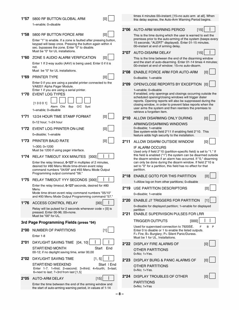
1*57 5800 RF BUTTON GLOBAL ARM [0] 1=enable; 0=disable
1*58 5800 RF BUTTON FORCE ARM [0] Enter "1" to enable. If a zone is faulted after pressing button,
keypad will beep once. Pressing the button again within 4 sec. bypasses the zone. Enter "0" to disable.
Must be "0" for UL installations.
1*60 ZONE 5 AUDIO ALARM VERIFICATION [0] Enter 1 If 2-way audio (AAV) is being used; Enter 0 if it is
not. Must be "0" for UL installations.
1*69 PRINTER TYPE [0] Enter 0 if you are using a parallel printer connected to the
VA8201 Alpha Pager Module. Enter 1 if you are using a serial printer. 1*70 EVENT LOG TYPES
[1 0 0 0 1]
Alarm
Chk
Byp
O/C
Syst
1=enable; 0=disable
1*71 12/24 HOUR TIME STAMP FORMAT [0] 0=12 hour; 1=24 hour
1*72 EVENT LOG PRINTER ON-LINE [0] 0=disable; 1=enable
1*73 PRINTER BAUD RATE [0] 1=300; 0=1200 Must be 1200 if using pager interface.
1*74 RELAY TIMEOUT XXX MINUTES [000] | | Enter the relay timeout, 0-127 in multiples of 2 minutes,
desired for #80 Menu Mode time-driven event relay command numbers "04/09" and #93 Menu Mode Output Programming output command "56."
1*75 RELAY TIMEOUT YYY SECONDS [000] | | Enter the relay timeout, 0-127 seconds, desired for #80
Menu Mode time driven event relay command numbers "05/10"
and #93 Menu Mode Output Programming command "57."
1*76 ACCESS CONTROL RELAY [00] | Relay will be pulsed for 2 seconds whenever code + [0] is
pressed. Enter 00-96; 00=none. Must be "00" for UL.
3rd Page Programming Fields (press *94)
2*00 NUMBER OF PARTITIONS [1]
Enter 1-8
2*01 DAYLIGHT SAVING TIME [04, 10] | | START/END MONTH Start End 00-12; if no daylight saving time, enter 00,00
2*02 DAYLIGHT SAVING TIME [1, 5] | START/END WEEKEND Start | End Enter 1-7. 1=first; 2=second; 3=third; 4=fourth; 5=last;
6=next to last; 7=3rd from last [1,5]
2*05 AUTO-ARM DELAY [15] | Enter the time between the end of the arming window and
the start of auto-arming warning period, in values of 1-14
times 4 minutes 00=instant; [15=no auto arm at all]. When this delay expires, the Auto-Arm Warning Period begins.
2*06 AUTO-ARM WARNING PERIOD [15] | This is the time during which the user is warned to exit the
premises prior to the auto-arming of the system (beeps every 15 seconds; "ALERT" displayed). Enter 01-15 minutes. 00=instant at end of arming delay.
2*07 AUTO-DISARM DELAY [15] | This is the time between the end of the disarming window
and the start of auto-disarming. Enter 01-14 times 4 minutes; 00=instant at end of window; 15=no auto-disarm.
2*08 ENABLE FORCE ARM FOR AUTO-ARM [0] 0=disable; 1=enable
2*09 OPEN/CLOSE REPORTS BY EXCEPTION [0] 1=enable; 0=disable If enabled, only openings and closings occurring outside the
scheduled opening/closing windows will trigger dialer reports. Opening reports will also be suppressed during the closing window, in order to prevent false reports when the user arms the system and then reenters the premises to retrieve a forgotten item.
2*10 ALLOW DISARMING ONLY DURING [0] ARMING/DISARMING WINDOWS 0=disable; 1=enable See system-wide field 2*11 if enabling field 2*10. This
feature adds high security to the installation.
2*11 ALLOW DISARM OUTSIDE WINDOW [0] IF ALARM OCCURS Used only if field 2*10 (partition-specific field) is set to "1." If
this field is enabled ("1") the system can be disarmed outside the disarm window if an alarm has occurred. If "0," disarming can only be done during the disarm window. If field 2*10 is set to "0" for a partition, this field has no effect for that partition.
2*18 ENABLE GOTO FOR THIS PARTITION [0] 1=Allow log-on from other partitions; 0=disable
2*19 USE PARTITION DESCRIPTORS [0] 0=disable; 1=enable
2*20 ENABLE J7 TRIGGERS FOR PARTITION [1] 0=disable for displayed partition; 1=enable for displayed
partition 2*21 ENABLE SUPERVISION PULSES FOR LRR
TRIGGER OUTPUTS [000] | | Used for supervised connection to 7920SE. F B P Enter 0 to disable or 1 to enable the listed outputs. F= Fire; B= Burglary; P= Silent Panic/Duress. Must be 1 for UL. Installations.
2*22 DISPLAY FIRE ALARMS OF [0] OTHER PARTITIONS 0=No; 1=Yes.
2*23 DISPLAY BURG & PANIC ALARMS OF [0] OTHER PARTITIONS 0=No; 1=Yes.
2*24 DISPLAY TROUBLES OF OTHER [0] PARTITIONS 0=No; 1=Yes

– 9 –
2*30 PAGER INSTALLED 1=Yes; 0=No [0] 2*31 DELAY PAGING
1
2
3
4
5
6
7
8
[0=disable]; 1=enable 2*32 TIME TO DELAY PAGING AFTER DIALER
000 – 024 times 10 seconds [000] | |
If field 2*31 is enabled, enter the time to delay before the pager sends the message.
2*33 PAGER 1 PHONE NUMBER
Enter 0-9 for each digit. Enter #11 for *, #12 for #, #13 for 2 second pause 2*34 PAGER 1 ID NUMBER
Enter the pager 1 ID number. Up to 10 digits. Press * after
the last digit if less than 10 is required.
2*35 PAGER 1 FORMAT [0] 0= Numeric; 1=ID; 2=Alphanumeric
2*36 PAGER 1 DELAY 1 [000] | | Enter the delay time 000-060 seconds. The delay occurs
between the phone number and the pager ID. NOTE: Program only if using numeric format.
2*37 PAGER 1 DELAY 2 [000] | | Enter the delay time 000-060 seconds. The delay occurs
between the pager ID and the event information. NOTE: Program only if using numeric format. 2*38 PAGER 1 PARTITION ENABLE
1
2
3
4
5
6
7
8
1=enable; [0=disable] 2*39 PAGER 1 TRIGGER EVENT ENABLES
Alarm
Trbl
Byp
O/C
Syst
1=enable; [0=disable] 2*40 PAGER 2 PHONE NUMBER
Enter 0-9 for each digit. Enter #11 for *, #12 for #, #13 for 2-second pause 2*41 PAGER 2 ID NUMBER
Enter the pager 2 ID number. Up to 10 digits. Press * after
the last digit if less than 10 is required.
2*42 PAGER 2 FORMAT [0] 0= Numeric; 1=ID; 2=Alphanumeric
2*43 PAGER 2 DELAY 1 [000] | | Enter the delay time 000-060 seconds. The delay occurs
between the phone number and the pager ID.
NOTE: Program only if using numeric format.
2*44 PAGER 2 DELAY 2 [000] | | Enter the delay time 000-060 seconds. The delay occurs
between the pager ID and the event information. NOTE: Program only if using numeric format.
2*45 PAGER 2 PARTITION ENABLE
1
2
3
4
5
6
7
8
1=enable; [0=disable] 2*46 PAGER 2 TRIGGER EVENT ENABLES
Alarm
Trbl
Byp
O/C
Syst
1=enable; [0=disable] 2*47 PAGER 3 PHONE NUMBER
Enter 0-9 for each digit. Enter #11 for *, #12 for #, #13 for 2-second pause 2*48 PAGER 3 ID NUMBER
Enter the pager 3 ID number. Up to 10 digits. Press * after
the last digit if less than 10 is required.
2*49 PAGER 3 FORMAT [0] 0= Numeric; 1=ID; 2=Alphanumeric
2*50 PAGER 3 DELAY 1 [000] | | Enter the delay time 000-060 seconds. The delay occurs
between the phone number and the pager ID. NOTE: Program only if using numeric format.
2*51 PAGER 3 DELAY 2 [000] | | Enter the delay time 000-060 seconds. The delay occurs
between the pager ID and the event information. NOTE: Program only if using numeric format. 2*52 PAGER 3 PARTITION ENABLE
1
2
3
4
5
6
7
8
1=enable; [0=disable] 2*53 PAGER 3 TRIGGER EVENT ENABLES
Alarm
Trbl
Byp
O/C
Syst
1=enable; [0=disable] 2*54 PAGER 4 PHONE NUMBER
Enter 0-9 for each digit. Enter #11 for *, #12 for #, #13 for 2-second pause 2*55 PAGER 4 ID NUMBER
Enter the pager 4 ID number. Up to 10 digits. Press * after
the last digit if less than 10 is required.
2*56 PAGER 4 FORMAT [0] 0= Numeric; 1=ID; 2=Alphanumeric

– 10 –
2*57 PAGER 4 DELAY 1 [000] | | Enter the delay time 000-060 seconds. The delay occurs
between the phone number and the pager ID. NOTE: Program only if using numeric format.
2*58 PAGER 4 DELAY 2 [000] | | Enter the delay time 000-060 seconds. The delay occurs
between the pager ID and the event information. NOTE: Program only if using numeric format.
2*59 PAGER 4 PARTITION ENABLE
1
2
3
4
5
6
7
8
1=enable; [0=disable] 2*60 PAGER 4 TRIGGER EVENT ENABLES
Alarm
Trbl
Byp
O/C
Syst
1=enable; [0=disable] 2*61 PAGER 5 PHONE NUMBER
Enter 0-9 for each digit. Enter #11 for *, #12 for #, #13 for 2-second pause 2*62 PAGER 5 ID NUMBER
Enter the pager 5 ID number. Up to 10 digits. Press * after
the last digit if less than 10 is required.
2*63 PAGER 5 FORMAT [0] 0= Numeric; 1=ID; 2=Alphanumeric
2*64 PAGER 5 DELAY 1 [000] | | Enter the delay time 000-060 seconds. The delay occurs
between the phone number and the pager ID. NOTE: Program only if using numeric format.
2*65 PAGER 5 DELAY 2 [000] | | Enter the delay time 000-060 seconds. The delay occurs
between the pager ID and the event information. NOTE: Program only if using numeric format. 2*66 PAGER 5 PARTITION ENABLE
1
2
3
4
5
6
7
8
1=enable; [0=disable] 2*67 PAGER 5 TRIGGER EVENT ENABLES
Alarm
Trbl
Byp
O/C
Syst
1=enable; [0=disable] 2*68 PAGER 6 PHONE NUMBER
Enter 0-9 for each digit. Enter #11 for *, #12 for #, #13 for 2-second pause 2*69 PAGER 6 ID NUMBER
Enter the pager 6 ID number. Up to 10 digits. Press * after the last digit if less than 10 is required.
2*70 PAGER 6 FORMAT [0] 0= Numeric; 1=ID; 2=Alphanumeric
2*71 PAGER 6 DELAY 1 [000] | | Enter the delay time 000-060 seconds. The delay occurs
between the phone number and the pager ID. NOTE: Program only if using numeric format.
2*72 PAGER 6 DELAY 2 [000] | | Enter the delay time 000-060 seconds. The delay occurs
between the pager ID and the event information. NOTE: Program only if using numeric format.
2*73 PAGER 6 PARTITION ENABLE
1
2
3
4
5
6
7
8
1=enable; [0=disable] 2*74 PAGER 6 TRIGGER EVENT ENABLES
Alarm
Trbl
Byp
O/C
Syst
1=enable; [0=disable] 2*75 PAGER 7 PHONE NUMBER
Enter 0-9 for each digit. Enter #11 for *, #12 for #, #13 for 2-second pause 2*76 PAGER 7 ID NUMBER
Enter the pager 7 ID number. Up to 10 digits. Press * after
the last digit if less than 10 is required.
2*77 PAGER 7 FORMAT [0] 0= Numeric; 1=ID; 2=Alphanumeric
2*78 PAGER 7 DELAY 1 [000] | | Enter the delay time 000-060 seconds. The delay occurs
between the phone number and the pager ID. NOTE: Program only if using numeric format.
2*79 PAGER 7 DELAY 2 [000] | | Enter the delay time 000-060 seconds. The delay occurs
between the pager ID and the event information. NOTE: Program only if using numeric format. 2*80 PAGER 7 PARTITION ENABLE
1
2
3
4
5
6
7
8
1=enable; [0=disable] 2*81 PAGER 7 TRIGGER EVENT ENABLES
Alarm
Trbl
Byp
O/C
Syst
1=enable; [0=disable] 2*82 PAGER 8 PHONE NUMBER
Enter 0-9 for each digit. Enter #11 for *, #12 for #,

– 11 –
#13 for 2-second pause 2*83 PAGER 8 ID NUMBER
Enter the pager 8 ID number. Up to 10 digits. Press * after
the last digit if less than 10 is required.
2*84 PAGER 8 FORMAT [0] 0= Numeric; 1=ID; 2=Alphanumeric
2*85 PAGER 8 DELAY 1 [000] | | Enter the delay time 000-060 seconds. The delay occurs
between the phone number and the pager ID. NOTE: Program only if using numeric format.
2*86 PAGER 8 DELAY 2 [000] | | Enter the delay time 000-060 seconds. The delay occurs
between the pager ID and the event information. NOTE: Program only if using numeric format.
2*87 PAGER 8 PARTITION ENABLE
1
2
3
4
5
6
7
8
1=enable; [0=disable] 2*88 PAGER 8 TRIGGER EVENT ENABLES
Alarm
Trbl
Byp
O/C
Syst
1=enable; [0=disable]
SUMMARY OF PROGRAMMING COMMANDS • To enter program mode, enter installer code + [8] + [0] +
[0] + [0] • To set standard defaults, press *97 • To change to next page of program fields, press *94 • To return to previous set of fields, press *99 • To erase account and phone number field entries,
press [*] + field number + [*] • To assign zone descriptors, press #93 + follow menu
prompts • To add custom words, press #93 + follow menu prompts • To enter Installer's Message, press #93 + follow menu
prompts • To exit program mode, enter *99 OR *98: *99 allows re-
access to programming mode by installer code. *98 prevents re-access to programming mode by installer code.