VISTA-100 Partitioned Security System User's Manual
66
N6020-2 Rev B 4/99 VISTA-100 Commercial Fire and Burglary Partitioned Security System 8VHU*XLGH * FIRE FIRE PULL ®
Transcript of VISTA-100 Partitioned Security System User's Manual

N6020-2 Rev B 4/99
VISTA-100 Commercial Fire and Burglary
Partitioned Security System
8VHU�*XLGH
*
FIRE FIRE
PULL
®
Ð 2 Ð
TABLE OF CONTENTS
SYSTEM OVERVIEW.................................... 3A Partitioned System................................ 3Zones.................................................... 3Fire Protection......................................... 4Burglary Protection .................................. 4Alarms................................................... 4Memory of Alarm...................................... 4Speed Key (Macros) ................................. 5Using Schedules...................................... 5Device Timers ......................................... 5Accessing other partitions (GOTO command) 5Master Keypad Operation.......................... 6Self-Help Feature ..................................... 6Phone Access & Voice Response ............... 6
ABOUT THE KEYPADS.................................. 7FUNCTIONS OF THE KEYPADS ...................... 8ENTRY/EXIT DELAYS.................................. 11SECURITY CODES & AUTHORITY LEVELS...... 12
Duress Code.......................................... 12Quick Arming ......................................... 12Authority Levels ..................................... 13To Add A User ........................................ 15To Change A User's Code ......................... 17To Delete A User ..................................... 17
ACCESSING OTHER PARTITIONS ................. 18GOTO Command..................................... 18Global Arming......................................... 18Master Keypad Operation......................... 19Common Lobby Operation......................... 20How User Codes Affect the Common Lobby. . 21
CHECKING FOR OPEN ZONES...................... 22DISPLAYING ALL ZONE DESCRIPTORS ......... 23
BYPASSING PROTECTION ZONES................ 24Quick Bypass........................................ 25Displaying Bypassed Protection Zones ....... 25ARMING PERIMETER ONLY (STAY)........... 26
ARMING PERIMETER ONLY (INSTANT) .......... 27ARMING ALL PROTECTION (AWAY)............... 28ARMING ALL PROTECTION (MAXIMUM) ......... 29DISARMING AND SILENCING ALARMS........... 30USING THE KEYSWITCH.............................. 31CHIME MODE............................................. 32VIEWING CENTRAL STATION MESSAGES...... 33PANIC KEYS.............................................. 34SPEED KEY (MACROS) ............................... 35ACCESS DOOR CONTROL ........................... 36USING #70 RELAY MENU MODE.................... 37USING SCHEDULES.................................... 38
Delaying The Closing Time........................ 39Temporary Open/Close Schedules............. 39
PROGRAMMING DEVICE TIMERS ................. 42TESTING THE SYSTEM................................ 44TROUBLE CONDITIONS............................... 46FIRE ALARM SYSTEM ................................. 48RECOMMENDATIONS FOR PROPERPROTECTYION .......................................... 49EMERGENCY EVACUATION......................... 51MAINTAINING YOUR SYSTEM ...................... 52QUICK GUIDE TO SYSTEM FUNCTIONS ......... 54SUMMARY OF AUDIBLE NOTIFICATION ......... 56GLOSSARY............................................... 57INSURANCE CREDIT REQUEST FORM ........... 63INDEX ...................................................... 65ADEMCO LIMITED WARRANTY ..................... 66EVENT LOGGING COMMANDS ..................... 67

Ð 3 Ð
SYSTEM OVERVIEWGeneral Congratulations on your ownership of an Ademco Partitioned
Security System. You've made a wise decision in choosing it, forit represents the latest in security protection technology today.Ademco is the world's largest manufacturer of security systemsand millions of premises are protected by Ademco systems.
This system offers you three forms of protection: burglary, fireand emergency. To realize the system's full potential, it isimportant that you feel comfortable in operating it. Your systemconsists of at least one Keypad which provides full control ofsystem operation, various sensors which provide perimeter andinterior burglary protection, plus a selected number of strategicallyplaced smoke or combustion detectors designed to provide earlywarning in case of fire.
The system uses microcomputer technology to monitor allprotection zones and system status and provides appropriateinformation for display on the Keypad(s) used with the system,and initiates appropriate alarms. Your system may also havebeen programmed to automatically transmit alarm or statusmessages over the phone lines to a central alarm monitoringstation.
A PartitionedSystem
Simply stated, a partitioned system shares one physical alarmsystem among different users, each with their own requirements.For the most part, you as a user need not know about otherusers and their structure in the system, but from time to time, youmay see display messages which indicate the system is in useby another user. Do not be concerned, this is normal. Refer to theACCESSING OTHER PARTITIONS section for additionalinformation.
Zones Your system's sensing devices have been assigned to various"zones." For example, the sensing device on your Entry/Exit doormay have been assigned to zone 01, sensing devices onwindows in the master bedroom to zone 02, and so on. Thesenumbers will appear on the display, along with an alphadescriptor for that zone (if programmed), when an alarm or troublecondition occurs.
Ð 4 Ð
SYSTEM OVERVIEW (cont'd)Fire Protection The fire protection portion of your security system (if used) is
always on and will sound an alarm if a fire condition is detected.Refer to the FIRE ALARM SYSTEM section for importantinformation concerning fire protection, smoke detectors andplanning emergency exit routes from your house.
BurglaryProtection
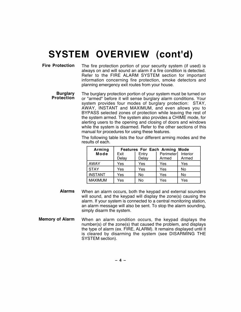
The burglary protection portion of your system must be turned onor "armed" before it will sense burglary alarm conditions. Yoursystem provides four modes of burglary protection: STAY,AWAY, INSTANT and MAXIMUM, and even allows you toBYPASS selected zones of protection while leaving the rest ofthe system armed. The system also provides a CHIME mode, foralerting users to the opening and closing of doors and windowswhile the system is disarmed. Refer to the other sections of thismanual for procedures for using these features.The following table lists the four different arming modes and theresults of each.
Arming Features For Each Arming ModeMode Exit Entry Perimeter Interior
Delay Delay Armed ArmedAWAY Yes Yes Yes YesSTAY Yes Yes Yes NoINSTANT Yes No Yes NoMAXIMUM Yes No Yes Yes
Alarms When an alarm occurs, both the keypad and external sounderswill sound, and the keypad will display the zone(s) causing thealarm. If your system is connected to a central monitoring station,an alarm message will also be sent. To stop the alarm sounding,simply disarm the system.
Memory of Alarm When an alarm condition occurs, the keypad displays thenumber(s) of the zone(s) that caused the problem, and displaysthe type of alarm (ex. FIRE, ALARM). It remains displayed until itis cleared by disarming the system (see DISARMING THESYSTEM section).
Ð 5 Ð
SYSTEM OVERVIEW (cont'd)Speed Key
(Macros)The system can store a string of up to 16 keystrokes, which canbe activated anytime by simply pressing the "D" key. Thisfeature can be used to make it easy to perform a complicatedprocedure (such as going to another partition to bypass a zone),or it can be used to simplify an everyday, repeated procedure.Refer to the SPEED KEY section for procedures for using thisfeature.
Using Schedules Your system may have been programmed with schedules forautomatically arming, disarming and activating various devicesand/or performing other system functions at predetermined times.Users can modify some of these schedules by manually delayinga closing time, using temporary schedules, or by programmingspecial user schedules. Refer to the USING SCHEDULESsection at the end of this manual for scheduling relatedprocedures.
Device Timers The system provides up to 20 "timers" which can be used tocontrol various devices, such as lights or appliances. Thesetimers are similar in concept to the individual appliance timers thatmight be purchased at a department store. The devices that canbe controlled are programmed into the system by the installer.Up to 16 of these devices can be programmed. Refer to thePROGRAMMING DEVICE TIMERS section for procedures.
To AccessAnother Partition(GOTO Command)
Each keypad is assigned a default partition for display purposes,and will show only that partition's information. But, if the user isauthorized, a keypad in one partition can be used to performsystem functions in another partition by using the G O T Ocommand. Note that only those partitions authorized andprogrammed by the installer can be accessed in this manner.To GOTO another partition, enter your security code, then press✱ followed by the desired partition number (1-8).
The keypad will remain in the new partition until directed to go toanother partition, or until 120 seconds has elapsed with nokeypad activity. Entering partition number 0 will return the keypadto its original partition.
Ð 6 Ð
SYSTEM OVERVIEW (cont'd)Master Keypad
OperationA "Master" keypad is one on which the status of all 8 partitions isdisplayed simultaneously. A user can get more information abouta certain partition by simply entering ✱ + the desired partitionnumber (1-8). To log on to the "Master" partition (9) using theGOTO command, a user must have access to all partitions.
Self-Help Feature Abbreviated user's instructions are built into the system that canbe easily viewed on the alpha keypad's message displayscreen. This feature will prove particularly useful if this manual isnot conveniently accessible when you need to perform a systemprocedure with which you are not familiar.
To view the abbreviated instructions:Simply press and hold down the function key of interest untilthe description starts to appear (about 5 seconds) and thenrelease it.
Refer to the FUNCTIONS OF THE KEYPAD section fordescriptions of each key function.
Phone Access &Voice Response
Capability
Your system may include a 4285 VIP module that will permit youto access the system via a Touch-tone phone, either on-premises or by call-in when away. The phone access feature willenable you to do the following:
¥ Receive synthesized voice messages over the telephoneregarding the status of the security system.
¥ Arm and disarm the system and perform most functioncommands via the telephone, with voice confirmation providedafter each command entry.
¥ Control 4204 relays through the #70 Manual Relay Activationmode.
Complete information regarding the use of this feature is providedin a separate manual entitled PHONE ACCESS USER'SGUIDE, which accompanies the 4285 VIP module.

Ð 7 Ð
ABOUT THE KEYPADSGeneral
IMPORTANT: If thekeypad beeps rapidly
upon entering thepremises, it indicates
that an alarm hasoccurred during your
absence. LEAVEIMMEDIATELY and
CONTACT THE POLICEfrom a nearby safe
location.
Your keypads allow you to control all system functions. Thekeypads feature a telephone style (digital) keypad and a LiquidCrystal Display (LCD) which shows the nature and location of alloccurrences. Keypad display back lighting is programmable toalways stay on or to light only when a key is pressed, then turnoff a few minutes later.
The keypads also feature a built-in sounder which will soundduring alarms and troubles. It will also "beep" during certainsystem functions, such as during entry/exit delay times, duringCHIME mode, and when depressing keys to arm and disarm thesystem (to acknowledge the key press). These sounds can beoptionally suppressed in some of your keypads (so as not todisturb other users of the system). Ask your installer if this hasbeen done.
The Keypad This system uses alpha keypads, which feature a 2-line, 32character alphanumeric Liquid Crystal Display (LCD). Thesekeypads can display system messages in friendly English.Abbreviated user's instructions can also be displayed (see SelfHelp paragraph in the SYSTEM OVERVIEW section). Thesekeypads can also be programmed with custom zone descriptors.
Ð 8 Ð
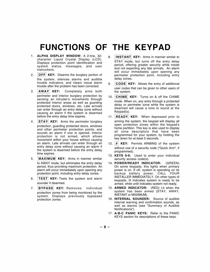
FUNCTIONS OF THE KEYPADÊ
1. ALPHA DISPLAY WINDOW: A 2-line, 32-character Liquid Crystal Display (LCD).Displays protection point identification andsystem status, messages, and userinstructions.
2. OFF KEY: Disarms the burglary portion ofthe system, silences alarms and audibletrouble indicators, and clears visual alarmtrouble after the problem has been corrected.
3. AWAY KEY: Completely arms bothperimeter and interior burglary protection bysensing an intruder's movements throughprotected interior areas as well as guardingprotected doors, windows, etc. Late arrivalscan enter through an entry delay zone withoutcausing an alarm if the system is disarmedbefore the entry delay time expires.
4. STAY KEY: Arms the perimeter burglaryprotection, guarding protected doors, windowsand other perimeter protection points, andsounds an alarm if one is opened. Interiorprotection is not armed, which allowsmovement within your house without causingan alarm. Late arrivals can enter through anentry delay zone without causing an alarm ifthe system is disarmed before the entry delaytime expires.
5. MAXIMUM KEY: Arms in manner similarto AWAY mode, but eliminates the entry delayperiod, thus providing maximum protection. Analarm will occur immediately upon opening anyprotection point, including entry delay zones.
6. TEST KEY: Tests the system and alarmsounder if disarmed.
7. BYPASS KEY: Removes indiv idualprotection zones from being monitored by thesystem. Displays previously bypassedprotection zones.
8. INSTANT KEY: Arms in manner similar toSTAY mode, but turns off the entry delayperiod, offering greater security while insideand not expecting any late arrivals. An alarmwill occur immediately upon opening anyperimeter protection point, including entrydelay zones.
9. CODE KEY: Allows the entry of additionaluser codes that can be given to other users ofthe system.
10. CHIME KEY: Turns on & off the CHIMEmode. When on, any entry through a protecteddelay or perimeter zone while the system isdisarmed will cause a tone to sound at theKeypad(s).
11. READY KEY: When depressed prior toarming the system, the keypad will display allopen protection zones within the keypad'shome partition. This key is also used to displayall zone descriptors that have beenprogrammed for your system, by holding thekey down for at least 5 seconds.
12. # KEY: Permits ARMING of the systemwithout use of a security code ("Quick Arm", ifprogrammed).
13. KEYS 0-9: Used to enter your individualsecurity access code(s).
14. POWER/READY INDICATOR: (GREEN)On some keypads, this lights when primarypower is on. If off, system is operating on itsbackup battery power. CALL YOURINSTALLER IMMEDIATELY. On other types ofkeypads, lit indicates system is ready to bearmed, while unlit indicates system not ready.
15. ARMED INDICATOR: (RED) Lit when thesystem has been armed (STAY, AWAY,INSTANT or MAXIMUM).
16. INTERNAL SOUNDER: Source of audibleinternal warning and confirmation sounds, aswell as alarms (see "Summary of AudibleNotifications").
17. A-B-C PANIC KEYS: Refer to the PANICKEYS section for descriptions of these keys.
Ð 9 Ð
1 2 3A
4 5 6B
7 8 9C
* 0 #D
OFF AWAY STAY
MAX TEST BYPASS
INSTANT CODE CHIME
READY
READYARMED
PANIC
A
B
C
D
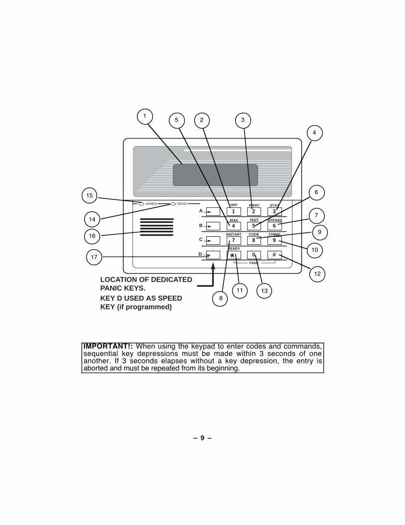
LOCATION OF DEDICATEDPANIC KEYS.KEY D USED AS SPEEDKEY (if programmed)
1
5 2 3
4
6
7
10
11
9
8
12
13
14
15
16
17
IMPORTANT!: When using the keypad to enter codes and commands,sequential key depressions must be made within 3 seconds of oneanother. If 3 seconds elapses without a key depression, the entry isaborted and must be repeated from its beginning.
Ð 10 Ð
ENTRY/EXIT DELAYSGeneral
InformationYour system has preset time delays, known as exit delay andentry delay. Whenever you arm your system, exit delay givesyou time to leave through the designated exit door without settingoff an alarm. Exit delay begins immediately after entering anyarming command, and applies to all modes of arming protection. Ifprogrammed, a slow beeping will sound throughout the exit delayperiod.
Entry Delay gives you time to disarm the system when youreenter through the designated entrance door. But the systemmust be disarmed before the entry delay period ends, or an alarmwill occur. The keypad will beep during the entry delay period,reminding you to disarm the system. You can also arm the systemwith no entry delay at all by using either INSTANT or MAXIMUMarming modes. These modes provide greater security while onthe premises or while away for extended periods of time. Seeyour installer for your delay times.
Ð 11 Ð
SECURITY CODES& AUTHORITY LEVELS
GeneralInformation
At the time of installation, you were assigned an authority leveland a personal four-digit security code, known only to you andyours. The security code must be entered when arming anddisarming the system. The authority level defines the systemfunctions that you can perform.
As an additional safety feature, other users that do not have aneed to know your code can be assigned different securitycodes, and each user can be given a different authority level.Users are identified by "user numbers", which are assigned whenassigning a user's security code.
All codes can be used interchangeably when performing systemfunctions within the limits of each code's authority level (a systemarmed with one user's code can be disarmed by another user'scode), with the exception of the Operator Level C code. SeeAUTHORITY LEVELS section on the following page for detailedinformation regarding user authority levels.
Duress Code This feature is intended for use when you are forced to disarm orarm the system under threat. When used, the system will actnormally, but can silently notify the central station of yoursituation, if that service has been provided. The duress code ispre-assigned by the installer during installation (auth. level 6).
Important: This code is useful only when the system isconnected to a central station.
Quick Arming Note that if "Quick Arming" was programmed by the installer, the# key can be pressed in place of the security code when arming
the system. The security code must always be used to disarmthe system, however.
Ð 12 Ð
SECURITY CODES& AUTHORITY LEVELS (cont'd)
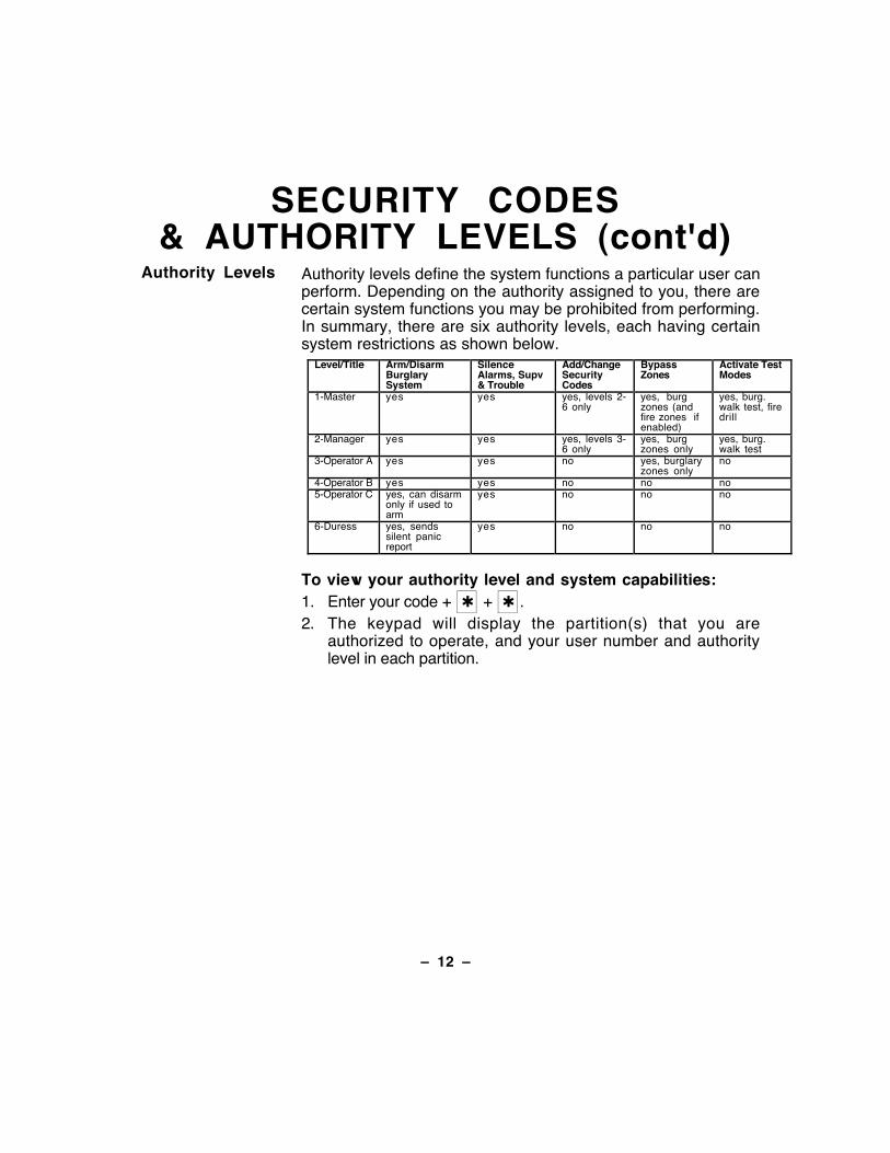
Authority Levels Authority levels define the system functions a particular user canperform. Depending on the authority assigned to you, there arecertain system functions you may be prohibited from performing.In summary, there are six authority levels, each having certainsystem restrictions as shown below.
Level/Title Arm/DisarmBurglarySystem
SilenceAlarms, Supv& Trouble
Add/ChangeSecurityCodes
BypassZones
Activate TestModes
1-Master yes yes yes, levels 2-6 only
yes, burgzones (andfire zones ifenabled)
yes, burg.walk test, firedrill
2-Manager yes yes yes, levels 3-6 only
yes, burgzones only
yes, burg.walk test
3-Operator A yes yes no yes, burglaryzones only
no
4-Operator B yes yes no no no5-Operator C yes, can disarm
only if used toarm
yes no no no
6-Duress yes, sendssilent panicreport
yes no no no
To view your authority level and system capabilities:1. Enter your code + ✱ + ✱ .2. The keypad will display the partition(s) that you are
authorized to operate, and your user number and authoritylevel in each partition.
Ð 13 Ð
SECURITY CODES& AUTHORITY LEVELS (cont'd)
General Rules onAuthority Levels
and Changes
¥ A user may not delete or change the user code of the SAME orHIGHER authority than which he is assigned.
¥ A user may only ADD users to a LOWER authority level.¥ A user may assign access codes only to those partitions to
which the user adding the code has access. (ex. a user withaccess to only partition 1 cannot assign codes in partition 2.)
¥ The only way to assign a user's authority level is by using the"Add A User" procedure. To change a user's authority level,that user must first be deleted, then added again.
¥ A user can only be DELETED or CHANGED from within thepartition he is assigned.
¥ User numbers must be entered as 3-digit entries. One- or two-digit user numbers must be preceded by a "0" (example, 003,004, etc.). Security codes are entered as 4-digit numbers.
¥ Before assigning a security code, be sure it does not conflictwith any DURESS code.
Note: When adding, changing or deleting users, all other alphakeypads in that partition will display "User Edit Mode Ð PleaseStand By", and key depressions (except Panic) at thosekeypads will be ignored. Panic key depressions will cause analarm and terminate user entry.
To Exit User EditMode
You can exit any of the user edit modes described on thefollowing pages at any time by doing the following:
1. Press either ✱ or # , or don't press any key for 10 seconds.
2. System returns to normal mode.
Ð 14 Ð
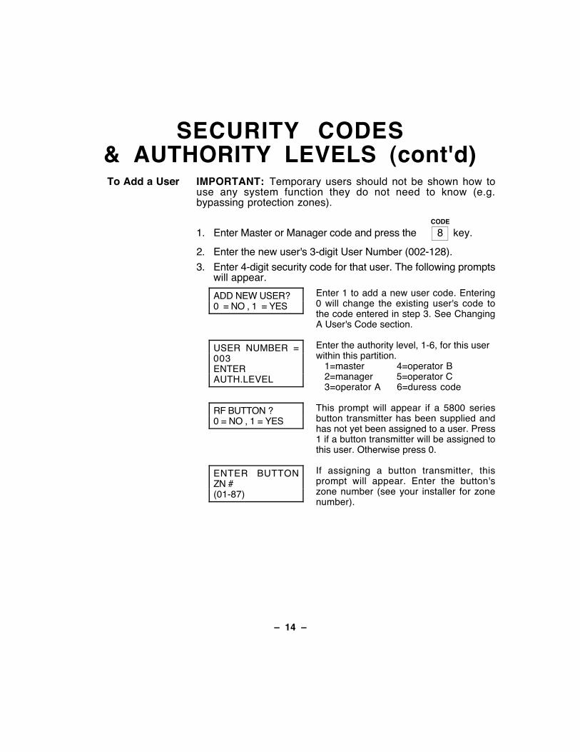
SECURITY CODES& AUTHORITY LEVELS (cont'd)To Add a User IMPORTANT: Temporary users should not be shown how to
use any system function they do not need to know (e.g.bypassing protection zones).
CODE
1. Enter Master or Manager code and press the Ê8Ê key.
2. Enter the new user's 3-digit User Number (002-128).
3. Enter 4-digit security code for that user. The following promptswill appear.
ADD NEW USER?0 = NO , 1 = YES
Enter 1 to add a new user code. Entering0 will change the existing user's code tothe code entered in step 3. See ChangingA User's Code section.
USER NUMBER =003ENTERAUTH.LEVEL
Enter the authority level, 1-6, for this userwithin this partition.
1=master 4=operator B2=manager 5=operator C3=operator A 6=duress code
RF BUTTON ?0 = NO , 1 = YES
This prompt will appear if a 5800 seriesbutton transmitter has been supplied andhas not yet been assigned to a user. Press1 if a button transmitter will be assigned tothis user. Otherwise press 0.
ENTER BUTTONZN #(01-87)
If assigning a button transmitter, thisprompt will appear. Enter the button'szone number (see your installer for zonenumber).
Ð 15 Ð
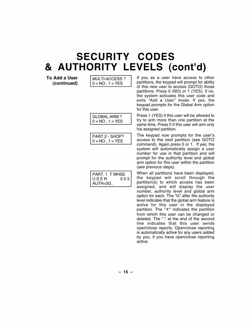
SECURITY CODES& AUTHORITY LEVELS (cont'd)To Add a User
(continued)MULTI-ACCESS ?0 = NO , 1 = YES
If you as a user have access to otherpartitions, the keypad will prompt for abilityof this new user to access (GOTO) thosepartitions. Press 0 (NO) or 1 (YES). If no,the system activates this user code andexits ÒAdd a UserÓ mode. If yes, thekeypad prompts for the Global Arm optionfor this user.
GLOBAL ARM ?0 = NO , 1 = YES
Press 1 (YES) if this user will be allowed totry to arm more than one partition at thesame time. Press 0 if this user will arm onlyhis assigned partition.
PART.2 - SHOP?0 = NO , 1 = YES
The keypad now prompts for the userÕsaccess to the next partition (see GOTOcommand). Again press 0 or 1. If yes, thesystem will automatically assign a usernumber for use in that partition and willprompt for the authority level and globalarm option for this user within the partition(see previous steps).
PART. 1 T WHSEU S E R 0 0 3AUTH=3G .
When all partitions have been displayed,the keypad will scroll through thepartition(s) to which access has beenassigned, and will display the usernumber, authority level and global armoption for each. The ÒGÓ after the authoritylevel indicates that the global arm feature isactive for this user in the displayedpartition. The "✴" indicates the partitionfrom which this user can be changed ordeleted. The "." at the end of the secondline indicates that this user sendsopen/close reports. Open/close reportingis automatically active for any users addedby you, if you have open/close reportingactive.
Ð 16 Ð
SECURITY CODES& AUTHORITY LEVELS (cont'd)
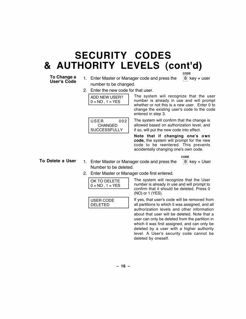
To Change aUser's Code
CODE
1. Enter Master or Manager code and press the 8 key + usernumber to be changed.
2. Enter the new code for that user.
ADD NEW USER?0 = NO , 1 = YES
The system will recognize that the usernumber is already in use and will promptwhether or not this is a new user. Enter 0 tochange the existing user's code to the codeentered in step 3.
U S E R 0 0 2CHANGED
SUCCESSFULLY
The system will confirm that the change isallowed based on authorization level, andif so, will put the new code into effect.
Note that if changing oneÕs owncode, the system will prompt for the newcode to be reentered. This preventsaccidentally changing one's own code.
To Delete a UserCODE
1. Enter Master or Manager code and press the 8 key + UserNumber to be deleted.
2. Enter Master or Manager code first entered.
OK TO DELETE0 = NO , 1 = YES
The system will recognize that the Usernumber is already in use and will prompt toconfirm that it should be deleted. Press 0(NO) or 1 (YES).
USER CODEDELETED
If yes, that user's code will be removed fromall partitions to which it was assigned, and allauthorization levels and other informationabout that user will be deleted. Note that auser can only be deleted from the partition inwhich it was first assigned, and can only bedeleted by a user with a higher authoritylevel. A User's security code cannot bedeleted by oneself.
Ð 17 Ð
ACCESSING OTHER PARTITIONS(GOTO Command and Global Arming)
To AccessAnother Partition
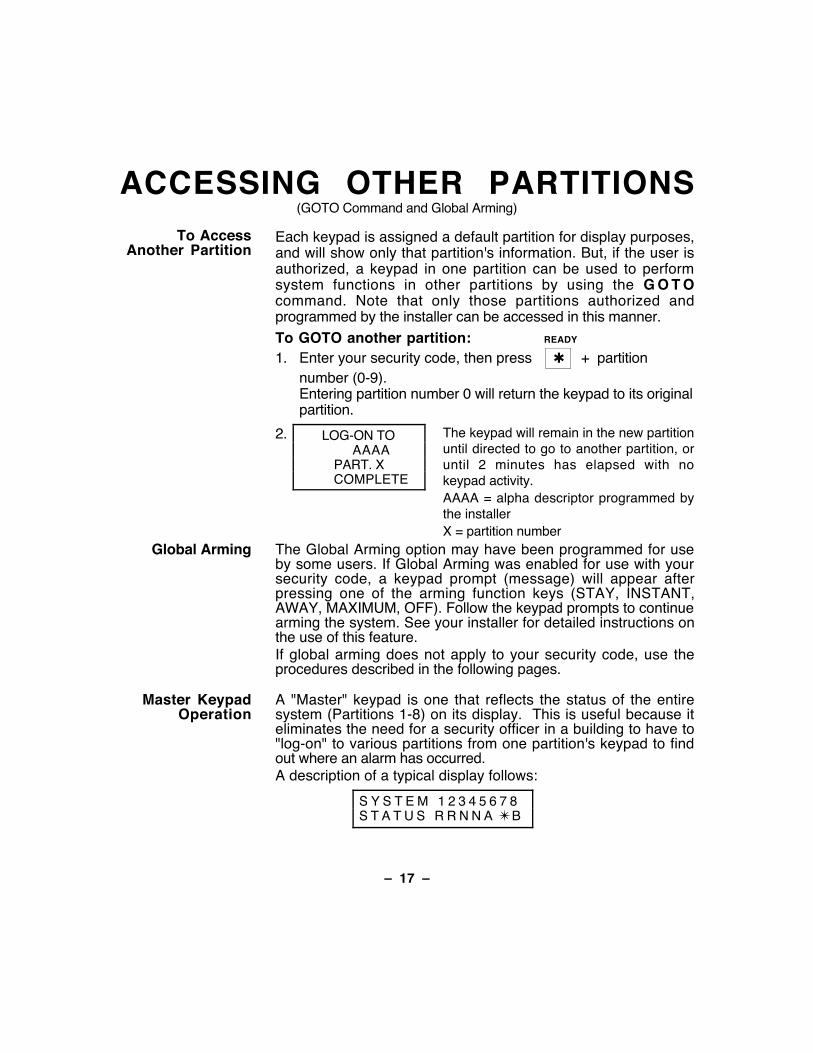
Each keypad is assigned a default partition for display purposes,and will show only that partition's information. But, if the user isauthorized, a keypad in one partition can be used to performsystem functions in other partitions by using the G O T Ocommand. Note that only those partitions authorized andprogrammed by the installer can be accessed in this manner.
To GOTO another partition: READY
1. Enter your security code, then press Ê✱Ê + partitionnumber (0-9).Entering partition number 0 will return the keypad to its originalpartition.
2. LOG-ON TOAAAA
PART. XCOMPLETE
The keypad will remain in the new partitionuntil directed to go to another partition, oruntil 2 minutes has elapsed with nokeypad activity.AAAA = alpha descriptor programmed bythe installerX = partition number
Global Arming The Global Arming option may have been programmed for useby some users. If Global Arming was enabled for use with yoursecurity code, a keypad prompt (message) will appear afterpressing one of the arming function keys (STAY, INSTANT,AWAY, MAXIMUM, OFF). Follow the keypad prompts to continuearming the system. See your installer for detailed instructions onthe use of this feature.If global arming does not apply to your security code, use theprocedures described in the following pages.
Master KeypadOperation
A "Master" keypad is one that reflects the status of the entiresystem (Partitions 1-8) on its display. This is useful because iteliminates the need for a security officer in a building to have to"log-on" to various partitions from one partition's keypad to findout where an alarm has occurred.A description of a typical display follows:
S Y S T E M 1 2 3 4 5 6 7 8S T A T U S R R N N A ✴ B
Ð 18 Ð
ACCESSING OTHER PARTITIONS(cont'd)
Master KeypadOperation
(continued)
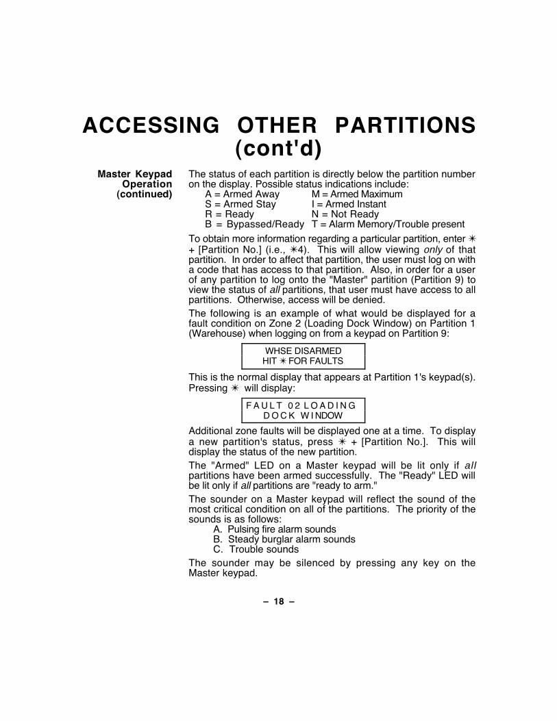
The status of each partition is directly below the partition numberon the display. Possible status indications include:
A = Armed Away M = Armed MaximumS = Armed Stay I = Armed InstantR = Ready N = Not ReadyB = Bypassed/Ready T = Alarm Memory/Trouble present
To obtain more information regarding a particular partition, enter ✴+ [Partition No.] (i.e., ✴4). This will allow viewing only of thatpartition. In order to affect that partition, the user must log on witha code that has access to that partition. Also, in order for a userof any partition to log onto the "Master" partition (Partition 9) toview the status of all partitions, that user must have access to allpartitions. Otherwise, access will be denied.The following is an example of what would be displayed for afault condition on Zone 2 (Loading Dock Window) on Partition 1(Warehouse) when logging on from a keypad on Partition 9:
WHSE DISARMEDHIT ✴ FOR FAULTS
This is the normal display that appears at Partition 1's keypad(s).Pressing ✴ will display:
F A U L T 0 2 L O A D I N GD O C K W I NDOW
Additional zone faults will be displayed one at a time. To displaya new partition's status, press ✴ + [Partition No.]. This willdisplay the status of the new partition.The "Armed" LED on a Master keypad will be lit only if allpartitions have been armed successfully. The "Ready" LED willbe lit only if all partitions are "ready to arm."The sounder on a Master keypad will reflect the sound of themost critical condition on all of the partitions. The priority of thesounds is as follows:
A. Pulsing fire alarm soundsB. Steady burglar alarm soundsC. Trouble sounds
The sounder may be silenced by pressing any key on theMaster keypad.
Ð 19 Ð
ACCESSING OTHER PARTITIONS(cont'd)
Common LobbyOperation
When an installation consists of a partition shared by usersof other partitions in a building, that shared partition may beassigned as the "common lobby" partition for the system.An example of this might be in a medical building wherethere are two doctor's offices and a common entrance area .
This option employs logic for automatic arming anddisarming of the common lobby . Partitions may be set toaffect and/or attempt to arm the common lobby. This willaffect the way the lobby will react when arming or disarmingactivity occurs in another partition.
Partitions set to affect the lobby will cause the following tooccur:
a. When the first partition that affects the lobby isdisarmed, the lobby will also be disarmed.
b. The common lobby cannot be armed unless everypartition selected to affect the lobby is armed.
c. Arming the last partition that affects the lobby will notautomatically attempt to arm the lobby.
Partitions set to arm the lobby will cause the following tooccur:
a. When the first partition that affects the lobby isdisarmed, the lobby will also be disarmed.
b. The common lobby cannot be armed unless everypartition selected to affect the lobby is armed.
c. Arming the last partition that is programmed to arm thelobby will automatically attempt to arm the lobby. If anyfaults exist in the lobby partition, or another partition thataffects the lobby is disarmed, the lobby cannot bearmed, and the message "UNABLE TO ARM LOBBYPARTITION" will be displayed.
Ð 20 Ð
ACCESSING OTHER PARTITIONS(cont'd)
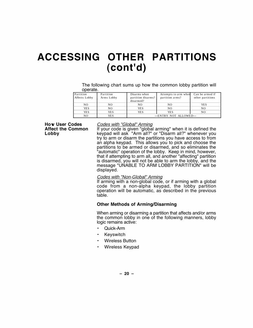
The following chart sums up how the common lobby partition willoperate.
Partition Partition Disarms when Attempts to arm when Can be armed ifAffects Lobby Arms Lobby partition disarms? partition arms? other partitions
disarmed?NO NO NO NO YESYES NO YES NO NOYES YES YES YES NONO YES ---ENTRY NOT ALLOWED---
How User CodesAffect the CommonLobby
Codes with "Global" ArmingIf your code is given "global arming" when it is defined thekeypad will ask "Arm all?" or "Disarm all?" whenever youtry to arm or disarm the partitions you have access to froman alpha keypad. This allows you to pick and choose thepartitions to be armed or disarmed, and so eliminates the"automatic" operation of the lobby. Keep in mind, however,that if attempting to arm all, and another "affecting" partitionis disarmed, you will not be able to arm the lobby, and themessage "UNABLE TO ARM LOBBY PARTITION" will bedisplayed.
Codes with "Non-Global" ArmingIf arming with a non-global code, or if arming with a globalcode from a non-alpha keypad, the lobby partitionoperation will be automatic, as described in the previoustable.
Other Methods of Arming/Disarming
When arming or disarming a partition that affects and/or armsthe common lobby in one of the following manners, lobbylogic remains active:¥ Quick-Arm¥ Keyswitch¥ Wireless Button¥ Wireless Keypad
Ð 21 Ð
CHECKING FOR OPEN ZONESUsing the ✱
READY Key
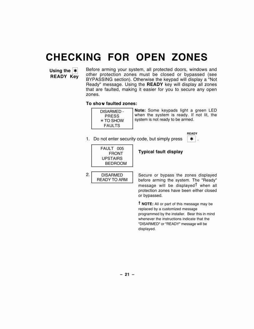
Before arming your system, all protected doors, windows andother protection zones must be closed or bypassed (seeBYPASSING section). Otherwise the keypad will display a "NotReady" message. Using the READY key will display all zonesthat are faulted, making it easier for you to secure any openzones.
To show faulted zones:
DISARMED -PRESS
✴ TO SHOWFAULTS
Note: Some keypads light a green LEDwhen the system is ready. If not lit, thesystem is not ready to be armed.
READY
1. Do not enter security code, but simply press Ê✱Ê .
FAULT 005FRONT
UPSTAIRSBEDROOM
Typical fault display
2. DISARMEDREADY TO ARM
Secure or bypass the zones displayedbefore arming the system. The "Ready"message will be displayed when allprotection zones have been either closedor bypassed.
NOTE: All or part of this message may bereplaced by a customized messageprogrammed by the installer. Bear this in mindwhenever the instructions indicate that the"DISARMED" or "READY" message will bedisplayed.
Ð 22 Ð
DISPLAYING ALLZONE DESCRIPTORS
Using the ✱
READY Key
The Alpha Keypads can also display all the zone descriptors thatare programmed in your system. The abbreviated instructions forthe R E A D Y key will appear first, followed by the zonedescriptors. Displaying all descriptors is useful when you need toknow the zone number of a particular zone, as when bypassingzones.
The "Disarmed-Ready to arm" message must be displayedbefore zone descriptors can be displayed.
READY
Press the Ê✱Ê key and hold down for at least 5 seconds.

Ð 23 Ð
BYPASSING ZONESUsing the 6
BYPASS KeyThis key is used when you want to arm your system with one ormore zones intentionally unprotected. Bypassed zones areunprotected and will not cause an alarm when violated while yoursystem is armed. All bypasses are removed when an OFFsequence (security code plus OFF) is performed. Bypasses arealso removed if the arming procedure that follows the bypasscommand is not successful.
To Bypass aZone:
1. Enter the security code. Then press BYPASS [6] and enterthe 3-digit number(s) of zone to be bypassed (ex. 005).
2. BYPASS 007FRONTUPSTAIRSBEDROOM
Typical bypassmessage
All bypassed zones wil l besequentially displayed when you arefinished entering the number of zonesto be bypassed. The console will thendisplay a bypass message as areminder that one or more zones isbypassed.
3. DISARMEDBYPASS
READY TO ARM
Arm the system as usual when thekeypad displays the "ready" to armmessage. Bypassed zones areunprotected and will not cause an alarmwhen violated while your system isarmed.
Note: All system zone bypasses are removed when an OFF sequence (security code + OFF) is performed.
Quick Bypass: Your system allows you to easily bypass all open (faulted)zones without having to enter zone numbers individually.
Note: All bypasses are removed when an OFF sequence(security code + OFF) is performed.
To use the Quick Bypass feature:BYPASS
1. Enter your security code and press Ê6Ê then press # . Allbypassed zones will be sequentially displayed as whenbypassing individual zones (described previously).
Ð 24 Ð
BYPASSING ZONES (cont'd)Bypassing
SystemSupervisory
Zones
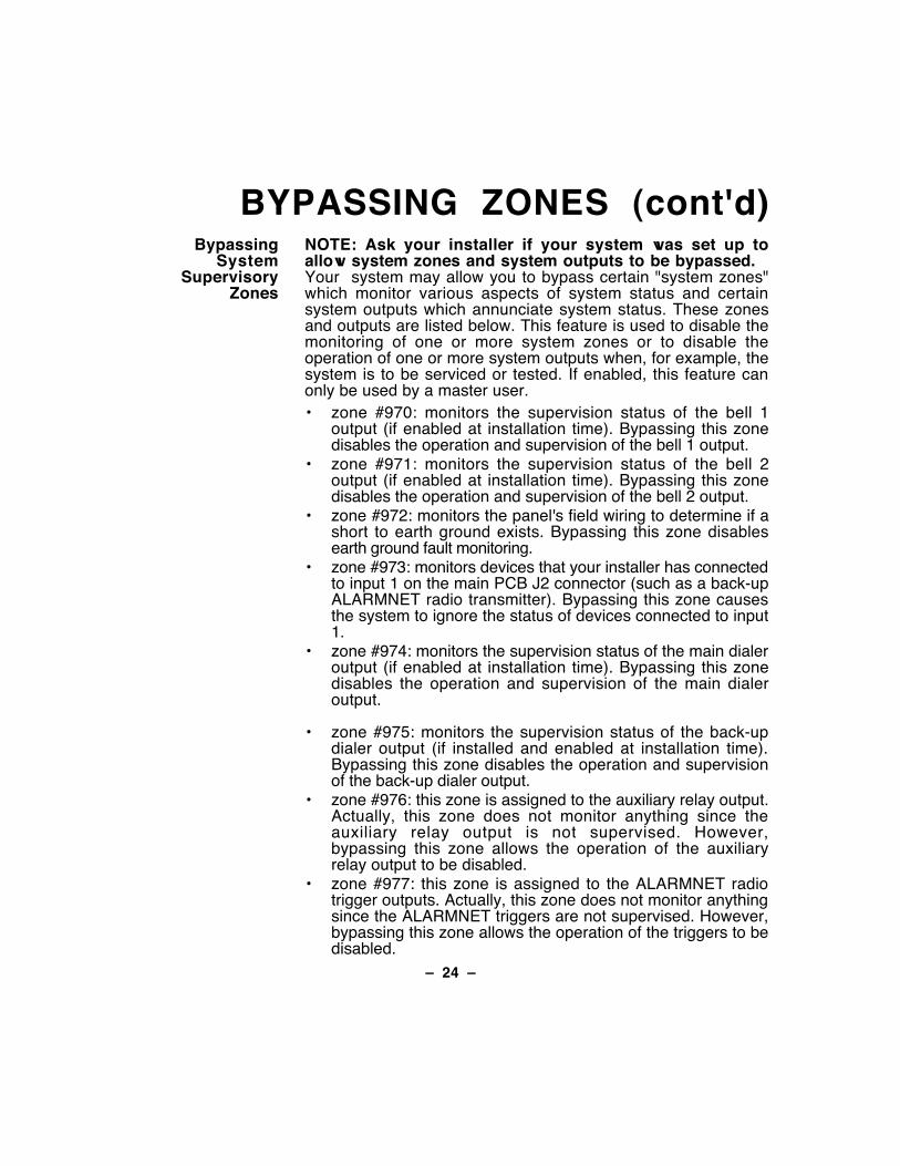
NOTE: Ask your installer if your system was set up toallow system zones and system outputs to be bypassed.Your system may allow you to bypass certain "system zones"which monitor various aspects of system status and certainsystem outputs which annunciate system status. These zonesand outputs are listed below. This feature is used to disable themonitoring of one or more system zones or to disable theoperation of one or more system outputs when, for example, thesystem is to be serviced or tested. If enabled, this feature canonly be used by a master user.¥ zone #970: monitors the supervision status of the bell 1
output (if enabled at installation time). Bypassing this zonedisables the operation and supervision of the bell 1 output.
¥ zone #971: monitors the supervision status of the bell 2output (if enabled at installation time). Bypassing this zonedisables the operation and supervision of the bell 2 output.
¥ zone #972: monitors the panel's field wiring to determine if ashort to earth ground exists. Bypassing this zone disablesearth ground fault monitoring.
¥ zone #973: monitors devices that your installer has connectedto input 1 on the main PCB J2 connector (such as a back-upALARMNET radio transmitter). Bypassing this zone causesthe system to ignore the status of devices connected to input1.
¥ zone #974: monitors the supervision status of the main dialeroutput (if enabled at installation time). Bypassing this zonedisables the operation and supervision of the main dialeroutput.
¥ zone #975: monitors the supervision status of the back-updialer output (if installed and enabled at installation time).Bypassing this zone disables the operation and supervisionof the back-up dialer output.
¥ zone #976: this zone is assigned to the auxiliary relay output.Actually, this zone does not monitor anything since theauxiliary relay output is not supervised. However,bypassing this zone allows the operation of the auxiliaryrelay output to be disabled.
¥ zone #977: this zone is assigned to the ALARMNET radiotrigger outputs. Actually, this zone does not monitor anythingsince the ALARMNET triggers are not supervised. However,bypassing this zone allows the operation of the triggers to bedisabled.
Ð 25 Ð
BYPASSING ZONES (cont'd)Displaying
Bypassed ZonesUsed to determine what zones have been previously bypassed.Bypassed zones can be displayed only when system isdisarmed.
BYPASS
1. Enter your security code and press Ê6Ê .
2. Wait for all bypassed zones to be sequentially displayed.
Ð 26 Ð
ARMING PERIMETER ONLY(With Entry Delay ON)
Using the 3STAY key
Use this key when you are staying home, but might expectsomeone to use the entrance door later.
When armed in STAY mode, the system will sound an alarm if aprotected door or window is opened, but you may otherwisemove freely throughout the premises. Late arrivals can enterthrough the entrance door without causing an alarm, but theymust disarm the system within the entry delay period or an alarmwill occur.
Close all perimeter windows and doors before arming (seeCHECKING FOR OPEN ZONES section)
STAY
1. Enter your security code and press Ê3Ê .
2. ARMED ***STAY***ZONE BYPASSED
The keypad will beep three times and willdisplay the armed message.
Note: "ZONE BYPASSED" in this displaysimply indicates that the interior zones ofprotection are not armed when usingSTAY mode.
Ð 27 Ð
ARMING PERIMETER ONLY(With Entry Delay OFF)
Using the7 INSTANT Key
Use this key when you are staying home and do not expectanyone to use the entrance door.
When armed in INSTANT mode, the system will sound an alarm ifa protected door or window is opened, but you may otherwisemove freely throughout the premises. The alarm will also soundimmediately if anyone opens the entrance door.
Close all perimeter windows and doors before arming (seeCHECKING FOR OPEN ZONES section)
INSTANT
1. Enter your security code and press Ê7Ê .
2. ARMED *INSTANT*ZONE BYPASSED
The keypad will beep three times and willdisplay the armed message.
Note: "ZONE BYPASSED" in this displaysimply indicates that the interior zones ofprotection are not armed when usingSTAY mode.
Ð 28 Ð
ARMING ALL PROTECTION(With Entry Delay ON)
Using the2 AWAY Key
Use this key when no one will be staying on the premises.
When armed in AWAY mode, the system will sound an alarm if aprotected door or window is opened, or if any movement isdetected inside the premises. You may leave through theentrance door during the exit delay period without causing analarm. You may also reenter through the entrance door, but mustdisarm the system within the entry delay period or an alarm willoccur.
Close all perimeter windows and doors before arming (seeCHECKING FOR OPEN ZONES section)
AWAY
1. Enter your security code and press Ê2Ê .
2. ARMED **AWAY**YOU MAY EXIT
NOW
The keypad will beep twice and will displaythe armed message.
Note: The "YOU MAY EXIT NOW" portionof the message disappears when exitdelay expires.
Ð 29 Ð
ARMING ALL PROTECTION(With Entry Delay OFF)
Using the4 MAXIMUM Key
Use this key when the premises will be vacant for extendedperiods of time such as vacations, etc., or when no one will bemoving through protected interior areas.
When armed in MAXIMUM mode, the system will sound an alarmif a protected door or window is opened, or if any movement isdetected inside the premises. You may leave through theentrance door during the exit delay period without causing analarm, but an alarm will be sounded as soon as someonereenters.
Close all perimeter windows and doors before arming (seeCHECKING FOR OPEN ZONES section)
MAXIMUM
1. Enter your security code and press Ê4Ê .
2. ARMED*MAXIMUM*
YOU MAY EXITNOW
The keypad will beep twice and will displaythe armed message.
Note: The "YOU MAY EXIT NOW" portionof the message disappears when exitdelay expires.
Ð 30 Ð
DISARMINGAND SILENCING ALARMS
Using the1 OFF Key
The OFF key is used to disarm the system and to silence alarmand trouble sounds. See "SUMMARY OF AUDIBLENOTIFICATION" section for information which will help you todistinguish between FIRE and BURGLARY alarm sounds.
IMPORTANT: If you return and the main burglary sounder is on,DO NOT enter the premises, but call the police from a nearbysafe location. If you return after an alarm has occurred and themain sounder has shut itself off, the keypad will beep rapidlyupon entering, indicating that an alarm has occurred during yourabsence. LEAVE IMMEDIATELY and CONTACT THE POLICEfrom a nearby safe location.
To disarm the system and silence burglary or fire alarms:OFF
1. Enter your security code and press Ê1Ê .
DISARMEDREADY TO ARM
2. The Ready message will be displayed (if no alarms haveoccurred while armed) and the keypad will beep once toconfirm that the system is disarmed.
Memory of Alarm The keypad displays the zone number and type of alarm for anyzone that has an alarm condition. These messages will remaindisplayed until cleared by a user. If an alarm has occurred, notethe zone number displayed on the keypad and repeat step 1above to clear the "Memory of Alarm" and restore the Readymessage display. If the Ready message will not display, go tothe displayed zone and remedy the fault (close windows, etc.). Ifthe fault cannot be remedied, notify the alarm agency.
If the system was armed when the alarm occurred, repeat step 1twice: once to disarm the system, a second time to clear thedisplay.
Ð 31 Ð
USING THE KEYSWITCHGeneral Your system may be equipped with a keyswitch for use when
arming and disarming. A red and green light on the keyswitchplate indicate the status of your system as follows:
Green Light: Lights when the system is disarmed andready to be armed (no open zones). Ifthe system is disarmed and the green lightis off, it indicates the system is not ready(one or more zones are open).
Red Light: Lights when system is armed or memoryof alarm exists.
Lit Steady: System is armed in AWAY mode.Slow Flashing: System is armed in STAY mode.
Rapid Flashing: Memory of alarm, indicating an alarm hasoccurred .
Arming To arm in the AWAY mode, turn the key to the right for 1/2second and release. Keypads will beep twice and the red lightwill stay on steady.
To arm in the STAY mode, turn the key to the right and hold forlonger than 3 seconds, then release. Keypads will beep threetimes and the red light will flash slowly.
Disarming To disarm the system, turn the key to the right and release. Ifan alarm has occurred, the red light will be flashing rapidly(memory of alarm).
Ð 32 Ð
CHIME MODEUsing the 9 Key Your system can be set to alert you to the opening of a door or
window while it is disarmed by using CHIME mode. Whenactivated, three tones will sound at the Keypad whenever aprotected perimeter door or window is opened, and the NotReady message will be displayed. Pressing the READY keywill display the open protection points.Note that Chime mode can be activated only when the system isdisarmed.
1. To turn Chime Mode on, enter the security code and pressÊ9Ê .
CHIME MODE ON The CHIME MODE ON message willappear for about two seconds thendisappear. To display this message again(to determine whether chime mode is onor off), simply press and hold down theCHIME key for 5 seconds.
2. To turn Chime Mode off, enter the security code and pressÊ9Ê again.
CHIME MODE OFF The CHIME MODE OFF message willappear for about two seconds thendisappear. To display this message again(to determine whether chime mode is onor off), simply press and hold down theCHIME key for 5 seconds.
Ð 33 Ð
VIEWING CENTRAL STATIONMESSAGES
GeneralInformation
Users of the system may periodically receive messages on theirdisplay screens from their monitoring agency or installer. When amessage is waiting to be viewed, the message shown below willappear.
MESSAGE. PRESS 0FOR 5 SECS.
1. Press and hold down 0 key for 5 seconds.
2. The message could take up to four screens to display all theinformation available.
Ð 34 Ð
PANIC KEYS(FOR MANUALLY ACTIVATING SILENT AND/OR AUDIBLE
ALARMS)Using
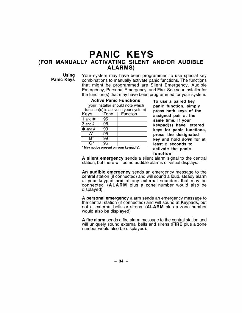
Panic KeysYour system may have been programmed to use special keycombinations to manually activate panic functions. The functionsthat might be programmed are Silent Emergency, AudibleEmergency, Personal Emergency, and Fire. See your installer forthe function(s) that may have been programmed for your system.
Active Panic Functions(your installer should note which
function(s) is active in your system)Keys Zone Function1 and ✱ 953 and # 96✱ and # 99
A* 95B* 99C* 96
* May not be present on your keypad(s).
To use a paired keypanic function, simplypress both keys of theassigned pair at thesame time. If yourkeypad(s) have letteredkeys for panic functions,press the designatedkey and hold down for atleast 2 seconds toactivate the panicfunction.
A silent emergency sends a silent alarm signal to the centralstation, but there will be no audible alarms or visual displays.
An audible emergency sends an emergency message to thecentral station (if connected) and will sound a loud, steady alarmat your keypad and at any external sounders that may beconnected (ALARM plus a zone number would also bedisplayed).
A personal emergency alarm sends an emergency message tothe central station (if connected) and will sound at Keypads, butnot at external bells or sirens. (ALARM plus a zone numberwould also be displayed)
A fire alarm sends a fire alarm message to the central station andwill uniquely sound external bells and sirens (FIRE plus a zonenumber would also be displayed).
Ð 35 Ð
SPEED KEY (MACROS)General
InformationThe "D" key can be used to activate a string of commands up to16 keystrokes. These commands are known as a macro and arestored in the system's memory. Typical Speed Key functionsinclude:
¥ Seldom used but repeatable sequences.¥ Arming sequences that involve first bypassing certain zones
before arming.¥ Relay activation sequences.
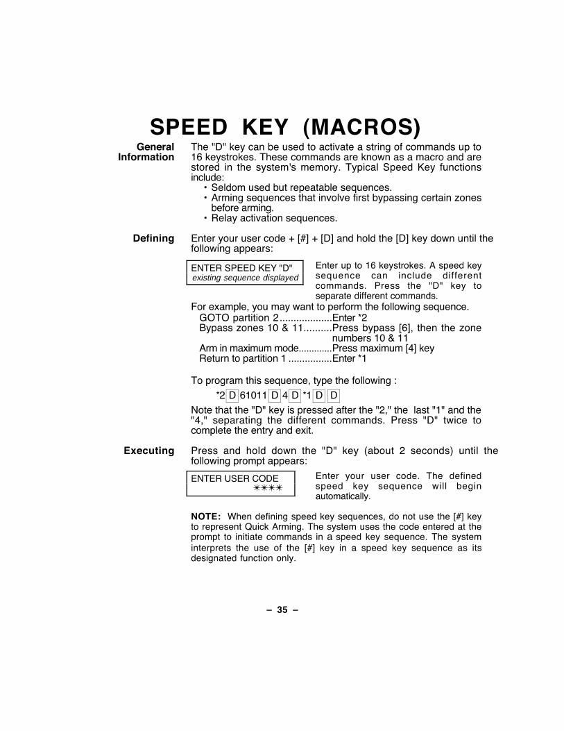
Defining Enter your user code + [#] + [D] and hold the [D] key down until thefollowing appears:
ENTER SPEED KEY "D"existing sequence displayed
Enter up to 16 keystrokes. A speed keysequence can include differentcommands. Press the "D" key toseparate different commands.
For example, you may want to perform the following sequence.GOTO partition 2................... Enter *2Bypass zones 10 & 11.......... Press bypass [6], then the zone
numbers 10 & 11Arm in maximum mode............. Press maximum [4] keyReturn to partition 1 ................ Enter *1
To program this sequence, type the following :
*2 D 61011 D 4 D *1 D D
Note that the "D" key is pressed after the "2," the last "1" and the"4," separating the different commands. Press "D" twice tocomplete the entry and exit.
Executing Press and hold down the "D" key (about 2 seconds) until thefollowing prompt appears:
ENTER USER CODE✴✴✴✴
Enter your user code. The definedspeed key sequence will beginautomatically.
NOTE: When defining speed key sequences, do not use the [#] keyto represent Quick Arming. The system uses the code entered at theprompt to initiate commands in a speed key sequence. The systeminterprets the use of the [#] key in a speed key sequence as itsdesignated function only.
Ð 36 Ð
ACCESS DOOR CONTROLGeneral
InformationYour system may be set up such that a locked access door (suchas in a lobby) can be unlocked using a keypad command. Askyour installer if this has been done in your system.
To activate this command:
Enter your security code and press 0 .
The door will unlock for 2 seconds.
Ð 37 Ð
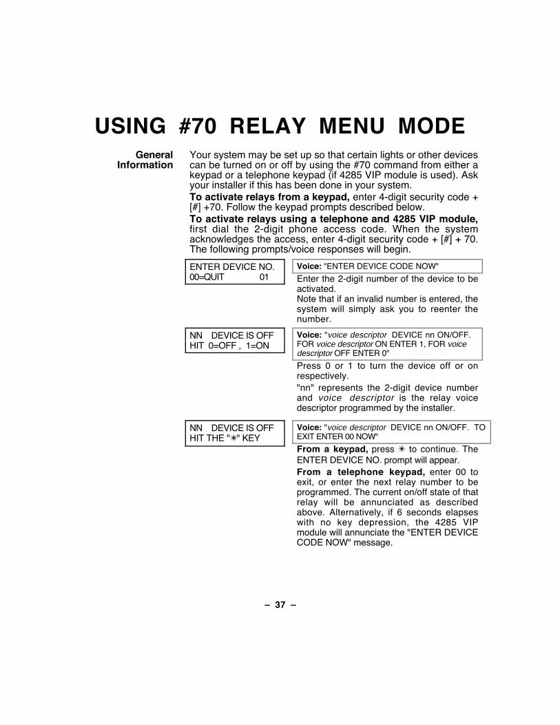
USING #70 RELAY MENU MODEGeneral
InformationYour system may be set up so that certain lights or other devicescan be turned on or off by using the #70 command from either akeypad or a telephone keypad (if 4285 VIP module is used). Askyour installer if this has been done in your system.To activate relays from a keypad, enter 4-digit security code +[#] +70. Follow the keypad prompts described below.To activate relays using a telephone and 4285 VIP module,first dial the 2-digit phone access code. When the systemacknowledges the access, enter 4-digit security code + [#] + 70.The following prompts/voice responses will begin.
ENTER DEVICE NO.00=QUIT 01
Voice: "ENTER DEVICE CODE NOW"
Enter the 2-digit number of the device to beactivated.Note that if an invalid number is entered, thesystem will simply ask you to reenter thenumber.
NN DEVICE IS OFFHIT 0=OFF , 1=ON
Voice: "voice descriptor DEVICE nn ON/OFF.FOR voice descriptor ON ENTER 1, FOR voicedescriptor OFF ENTER 0"
Press 0 or 1 to turn the device off or onrespectively."nn" represents the 2-digit device numberand voice descriptor is the relay voicedescriptor programmed by the installer.
NN DEVICE IS OFFHIT THE "✴" KEY
Voice: "voice descriptor DEVICE nn ON/OFF. TOEXIT ENTER 00 NOW"
From a keypad, press ✴ to continue. TheENTER DEVICE NO. prompt will appear.From a telephone keypad, enter 00 toexit, or enter the next relay number to beprogrammed. The current on/off state of thatrelay will be annunciated as describedabove. Alternatively, if 6 seconds elapseswith no key depression, the 4285 VIPmodule will annunciate the "ENTER DEVICECODE NOW" message.
Ð 38 Ð
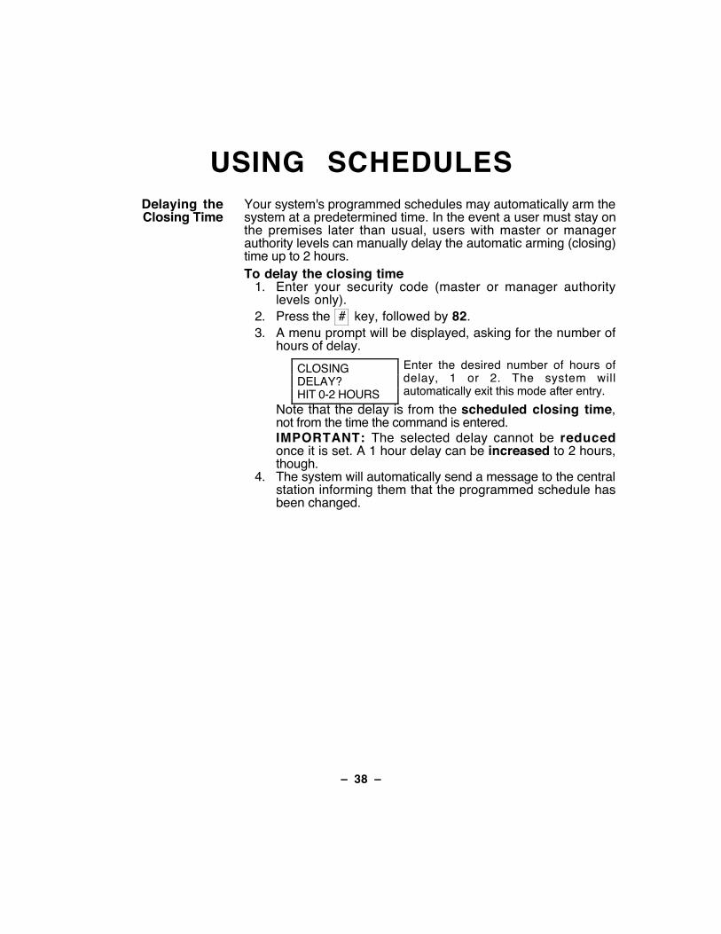
USING SCHEDULESDelaying theClosing Time
Your system's programmed schedules may automatically arm thesystem at a predetermined time. In the event a user must stay onthe premises later than usual, users with master or managerauthority levels can manually delay the automatic arming (closing)time up to 2 hours.To delay the closing time
1. Enter your security code (master or manager authoritylevels only).
2. Press the # key, followed by 82.3. A menu prompt will be displayed, asking for the number of
hours of delay.
CLOSINGDELAY?HIT 0-2 HOURS
Enter the desired number of hours ofdelay, 1 or 2. The system willautomatically exit this mode after entry.
Note that the delay is from the scheduled closing time,not from the time the command is entered.IMPORTANT: The selected delay cannot be reducedonce it is set. A 1 hour delay can be increased to 2 hours,though.
4. The system will automatically send a message to the centralstation informing them that the programmed schedule hasbeen changed.
Ð 39 Ð
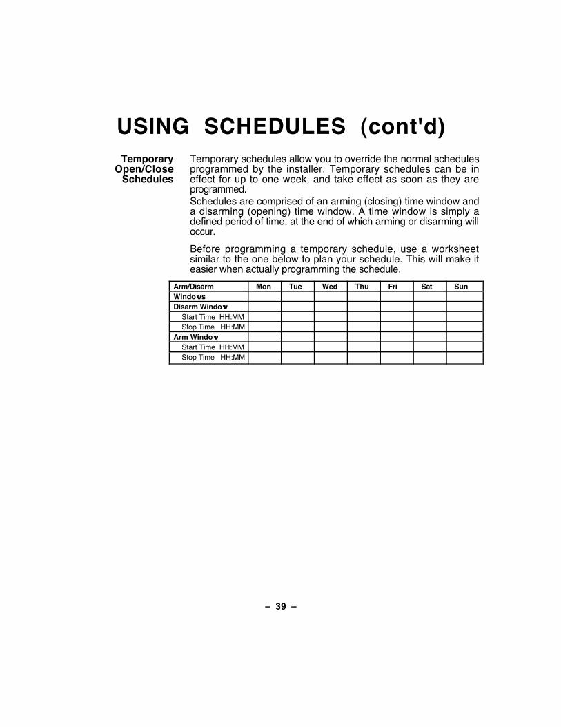
USING SCHEDULES (cont'd)Temporary
Open/CloseSchedules
Temporary schedules allow you to override the normal schedulesprogrammed by the installer. Temporary schedules can be ineffect for up to one week, and take effect as soon as they areprogrammed.Schedules are comprised of an arming (closing) time window anda disarming (opening) time window. A time window is simply adefined period of time, at the end of which arming or disarming willoccur.
Before programming a temporary schedule, use a worksheetsimilar to the one below to plan your schedule. This will make iteasier when actually programming the schedule.
Arm/Disarm Mon Tue Wed Thu Fri Sat SunWindowsDisarm Window
Start Time HH:MMStop Time HH:MM
Arm WindowStart Time HH:MMStop Time HH:MM

Ð 40 Ð
USING SCHEDULES (cont'd)Programming
TemporarySchedules
Temporary schedules only affect the partition from which it isentered. Temporary schedules can be reused at later datessimply by scrolling (by pressing #) to the DAYS? prompt(described below) and activating the appropriate days. Thisshould be considered when defining daily time windows. Notethat only users with authority level of manager or higher canprogram temporary schedules.
To program temporary schedules:1. Enter your security code.2. Press the # key followed by 81.3. The following prompts will appear.
MON DISARMWIND.07:45AM 08:45AM
The cursor will be positioned on the tensof hours digit of the start time forMonday's disarm window. Enter thedesired hour. Press * to move to theminutes field. The minutes are enteredin the same manner. The AM/PMindication is changed by hitting any key,0-9, while the cursor is under the letterA/P position. Repeat for the stop timeentry. Press the * key to move to thearming window for Monday.Press # to move to the next screendisplay without making changes.
MON ARMWINDOW07:45AM 08:45AM
The cursor will be positioned on the tensof hours digit of the start time for the armwindow. Repeat the previous steps toenter the start and stop time for Monday'sarming window.
Ð 41 Ð
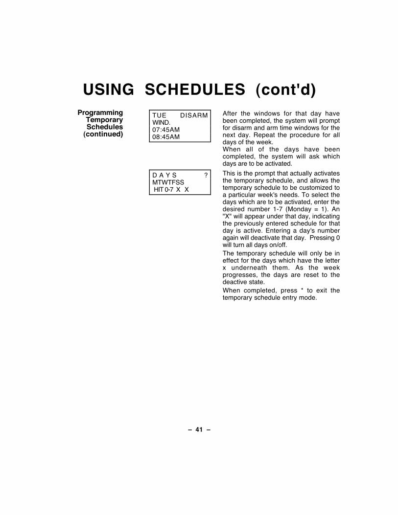
USING SCHEDULES (cont'd)Programming
TemporarySchedules
(continued)
TUE DISARMWIND.07:45AM08:45AM
After the windows for that day havebeen completed, the system will promptfor disarm and arm time windows for thenext day. Repeat the procedure for alldays of the week.When all of the days have beencompleted, the system will ask whichdays are to be activated.
D A Y S ?MTWTFSS HIT 0-7 X X
This is the prompt that actually activatesthe temporary schedule, and allows thetemporary schedule to be customized toa particular week's needs. To select thedays which are to be activated, enter thedesired number 1-7 (Monday = 1). An"X" will appear under that day, indicatingthe previously entered schedule for thatday is active. Entering a day's numberagain will deactivate that day. Pressing 0will turn all days on/off.The temporary schedule will only be ineffect for the days which have the letterx underneath them. As the weekprogresses, the days are reset to thedeactive state.When completed, press * to exit thetemporary schedule entry mode.
Ð 42 Ð
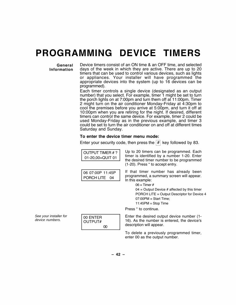
PROGRAMMING DEVICE TIMERSGeneral
InformationDevice timers consist of an ON time & an OFF time, and selecteddays of the week in which they are active. There are up to 20timers that can be used to control various devices, such as lightsor appliances. Your installer will have programmed theappropriate devices into the system (up to 16 devices can beprogrammed).Each timer controls a single device (designated as an outputnumber) that you select. For example, timer 1 might be set to turnthe porch lights on at 7:00pm and turn them off at 11:00pm. Timer2 might turn on the air conditioner Monday-Friday at 4:30pm tocool the premises before you arrive at 5:00pm, and turn it off at10:00pm when you are retiring for the night. If desired, differenttimers can control the same device. For example, timer 2 could beused Monday-Friday as in the previous example, and timer 3could be set to turn the air conditioner on and off at different timesSaturday and Sunday.
To enter the device timer menu mode:Enter your security code, then press the # key followed by 83.
OUTPUT TIMER # ? 01-20,00=QUIT 01
Up to 20 timers can be programmed. Eachtimer is identified by a number 1-20. Enterthe desired timer number to be programmed(1-20). Press * to accept entry.
06 07:00P 11:45PPORCH LITE 04
If that timer number has already beenprogrammed, a summary screen will appear.In this example:
06 = Timer #04 = Output Device # affected by this timerPORCH LITE = Output Descriptor for Device 407:00PM = Start Time;11:45PM = Stop Time
Press * to continue.
See your installer fordevice numbers.
00 ENTEROUTPUT# 00
Enter the desired output device number (1-16). As the number is entered, the device'sdescription will appear.
To delete a previously programmed timer,enter 00 as the output number.
Ð 43 Ð
PROGRAMMING DEVICE TIMERS(cont'd)
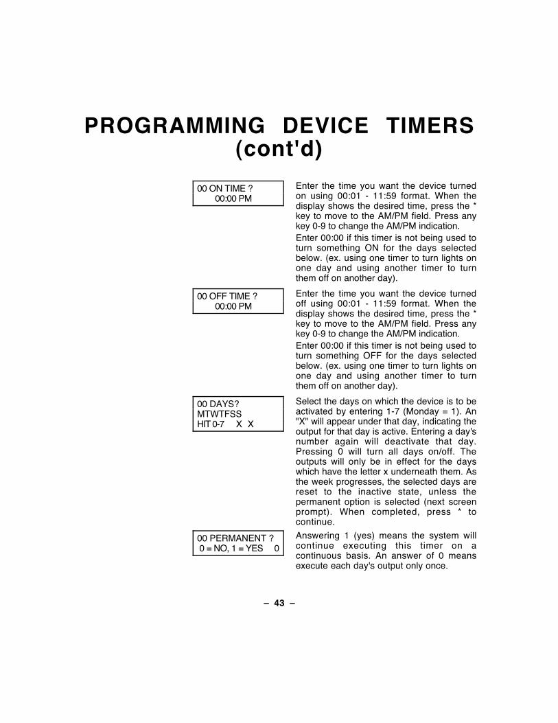
00 ON TIME ? 00:00 PM
Enter the time you want the device turnedon using 00:01 - 11:59 format. When thedisplay shows the desired time, press the *key to move to the AM/PM field. Press anykey 0-9 to change the AM/PM indication.Enter 00:00 if this timer is not being used toturn something ON for the days selectedbelow. (ex. using one timer to turn lights onone day and using another timer to turnthem off on another day).
00 OFF TIME ? 00:00 PM
Enter the time you want the device turnedoff using 00:01 - 11:59 format. When thedisplay shows the desired time, press the *key to move to the AM/PM field. Press anykey 0-9 to change the AM/PM indication.Enter 00:00 if this timer is not being used toturn something OFF for the days selectedbelow. (ex. using one timer to turn lights onone day and using another timer to turnthem off on another day).
00 DAYS?MTWTFSSHIT 0-7 X X
Select the days on which the device is to beactivated by entering 1-7 (Monday = 1). An"X" will appear under that day, indicating theoutput for that day is active. Entering a day'snumber again will deactivate that day.Pressing 0 will turn all days on/off. Theoutputs will only be in effect for the dayswhich have the letter x underneath them. Asthe week progresses, the selected days arereset to the inactive state, unless thepermanent option is selected (next screenprompt). When completed, press * tocontinue.
00 PERMANENT ? 0 = NO, 1 = YES 0
Answering 1 (yes) means the system willcontinue executing this timer on acontinuous basis. An answer of 0 meansexecute each day's output only once.
Ð 44 Ð
TESTING THE BURGLARYSYSTEM
(TO BE CONDUCTED WEEKLY)
Using the5 TEST Key
The TEST key puts your system into the Walk Test mode, whichallows each protection point to be checked for proper operation.
1. Disarm the system and close all protected windows, doors,etc. READY should be displayed.
TEST
2. Enter your security code and press the 5 key.
3. The external sounder should sound for 3 seconds and thenturn off. If the sounder does not sound, it may be due todialer communication activity. Wait a few minutes and tryagain. If the sounder still does not sound, CALL FORSERVICE IMMEDIATELY.
4. The keypad will sound a single beep every 15 seconds as areminder that the system is in Test mode.
Note that no alarm reports will be sent to the centralmonitoring station while the system is in Test mode.
5. Open and close each protected door and window in turn andlisten for three beeps. The identification of each faultedprotection point should appear on the display.
6. Walk in front of any interior motion detectors (if used) andlisten for three beeps as movement is detected. Theidentification of the detector should appear on the displaywhen it is activated. If a problem is experienced with anyprotection point (no confirming sounds, no display), CALLFOR SERVICE IMMEDIATELY.
7. Turn off Test mode by entering the security code andpressing the OFF key.
Ð 45 Ð
FIRE ALARM SYSTEMGeneral Your fire alarm system (if installed) is on 24 hours a day,
providing continuous protection. In the event of an emergency,the installed smoke and heat detectors will automatically sendsignals to your Control/Communicator, triggering a loud,interrupted sound from the Keypad. An interrupted sound willalso be produced by optional exterior sounders. A FIRE messagewill appear at your Keypad and remain on until you silence thealarm.
In Case Of FireAlarm
1. Should you become aware of a fire emergency before yourdetectors sense the problem, go to your nearest Keypad andmanually initiate an alarm by pressing the panic key pairassigned as FIRE emergency (if programmed by the installer)and hold down for at least 2 seconds.
2. Evacuate all occupants from the premises.3. If flames and/or smoke are present, leave the premises and
notify your local Fire Department immediately.4. If no flames or smoke are apparent, investigate the cause of
the alarm. The zone descriptor of the zone(s) in an alarmcondition will appear at the Keypad.
Silencing A FireAlarm
1. Silence the alarm by entering your code and pressing theOFF key. To clear the display, enter your code and press theOFF key again.
2. If the Keypad does not indicate a READY condition after thesecond OFF sequence, press the READY key to displaythe zone(s) that are faulted. Be sure to check that smokedetectors are not responding to smoke or heat producingobjects in their vicinity. Should this be the case, eliminate thesource of heat or smoke.
3. If this does not remedy the problem, there may still be smokein the detector. Clear it by fanning the detector for about 30seconds.
4. When the problem has been corrected, clear the display byentering your code and pressing the OFF key.
Ð 46 Ð
TESTING THE FIRE SYSTEMFire Drill Test
(code + [#] + 69)This test causes fire bells to be activated (in either steadyor pulsing manner as programmed in the system) for thepurpose of conducting a fire drill or a bell test. This test canonly be activated by the installer or a master user asfollows:
1. Enter the corresponding security code and press [#] +69 (make sure the burglary portion of the system isdisarmed). Consoles will display "FIRE DRILL ACTIVE"while this test is active.
2. The test may be stopped by entering any securitycode and pressing OFF.Note that the system continues to monitor all 24 hourzones (fire, panic, etc.) while this test is active, and willend the test when an alarm condition is detected. Thistest should be conducted at periodic intervals asdetermined by the local authority having jurisdiction.
Ð 47 Ð
TROUBLE CONDITIONSTypical Trouble
DisplaysThe word C H E C K or T R B L on the Keypad's display,accompanied by a rapid "beeping" at the Keypad, indicates thatthere is a trouble condition in the system.To silence the beeping sound for "check" conditions, pressany key.
1. A display of "CHECK" or "TRBL" accompanied by a displayof "CALL SERVICE" indicates that a problem exists with thesystem that eliminates some of the protection. CALL FORSERVICE IMMEDIATELY.
2. A display of "CHECK" or "TRBL" accompanied by a displayof one or more zone descriptors indicates that a problemexists with those zone(s)*. First, determine if the zone(s)displayed are intact and make them so if they are not. If theproblem has been corrected, key an OFF sequence (SecurityCode plus OFF) to clear the display. If the display persists,CALL FOR SERVICE IMMEDIATELY.
3. A display of "CHECK" or "TRBL" accompanied by a numericdisplay of "6XX," where XX = 01-16, indicates a trouble on asupervised relay (corresponding relay number 01-16)
4. A display of "CHECK" or "TRBL"accompanied by a numericdisplay of "8XX," where XX = 00-31, indicates a trouble on aperipheral device (connected to the panel's keypad terminals)of the corresponding device address (00-31)
5. A display of "CHECK" or "TRBL" accompanied by a numericdisplay of "9XX," where XX = 00-99, indicates that a systemtrouble exists (dialers, bell outputs, ground fault, etc). Thesezones are as follows:
970: Bell 1 Output
971: Bell 2 Output
972: Earth Ground Fault973: J2 Trigger Output974: Dialer 1
975: Dialer 2987: Voice Module988: 2nd RF Receiver -
not receiving signals990: 1st RF Receiver -
not receiving signals
If the problem has been corrected, enter the [Security Code]plus [OFF] twice to clear the display.
Ð 48 Ð
TROUBLE CONDITIONS (cont'd)6. A display of "COMM. FAILURE" at the Keypad indicates
that a failure has occurred in the telephone communicationportion of your system. CALL FOR SERVICEIMMEDIATELY.
7. A display of "SYSTEM LO BAT" per minute "beeping" at theKeypad indicates that a low system battery condition exists.CALL FOR SERVICE IMMEDIATELY.
8. A display of "LO BAT" and a zone descriptor, accompaniedby a once per minute "beeping" at the Keypad indicates thata low battery condition exists in the wireless transmitter**displayed. CALL FOR SERVICE IMMEDIATELY.
9. A display of "MODEM COMM" indicates that the control ison-line with the central station's remote computer. The controlwill not operate while on-line.
Power Failure If the POWER indicator is off, operating power for the systemhas stopped and is inoperative. CALL FOR SERVICEIMMEDIATELY. If the POWER indicator is on, but the message"AC LOSS" is displayed, the Keypad is operating on batterypower only. If only some lights are out on the premises, checkcircuit breakers and fuses and reset or replace as necessary.CALL FOR SERVICE IMMEDIATELY if AC power cannot berestored.
SERVICING INFORMATIONYour local Ademco dealer is the person best qualified to serviceyour alarm system. Arranging some kind of regular serviceprogram with him is advisable.Your local Ademco dealer is:Name: Address:
Phone:
Ð 49 Ð
RECOMMENDATIONSFOR PROPER PROTECTION
THE FOLLOWING RECOMMENDATIONS FOR THE LOCATION OF FIRE ANDBURGLARY DETECTION DEVICES HELP PROVIDE PROPER COVERAGEFOR THE PROTECTED PREMISES.
RECOMMENDATIONS FOR SMOKE AND HEAT DETECTORSWith regard to the number and placement of smoke/heat detectors, wesubscribe to the recommendations contained in the National Fire ProtectionAssociation's (NFPA) Standard #72 noted below.
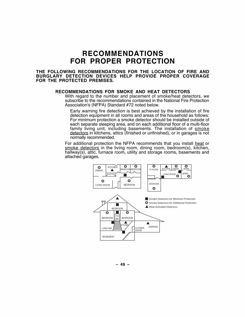
Early warning fire detection is best achieved by the installation of firedetection equipment in all rooms and areas of the household as follows:For minimum protection a smoke detector should be installed outside ofeach separate sleeping area, and on each additional floor of a multi-floorfamily living unit, including basements. The installation of smokedetectors in kitchens, attics (finished or unfinished), or in garages is notnormally recommended.
For additional protection the NFPA recommends that you install heat orsmoke detectors in the living room, dining room, bedroom(s), kitchen,hallway(s), attic, furnace room, utility and storage rooms, basements andattached garages.
DININGKITCHEN
BEDROOM
BEDROOM
BEDROOM
BEDROOM
LIVING ROOM
✪
✪
✪ ✪
✪
▲
▲
BEDROOM
BDRM
BDRM
DINING
LIVING ROOM
TV ROOM KITCHEN
■■
■
✪
✪
✪
✪ ✪
✪
▲
✪
✪
✪
BEDROOM BEDROOMTOBR
■
■
■
■
■
LVNG RM
BASEMENT
KTCHN▲
▲
. CLOSEDDOOR
GARAGE▲
Smoke Detectors for Minimum Protection
Smoke Detectors for Additional Protection
Heat-Activated Detectors
Ð 50 Ð
RECOMMENDATIONSFOR PROPER PROTECTION (cont.)
In addition, we recommend the following:¥ Install a smoke detector inside every bedroom where a smoker sleeps.¥ Install a smoke detector inside every bedroom where someone sleeps
with the door partly or completely closed. Smoke could be blocked bythe closed door. Also, an alarm in the hallway outside may not wake upthe sleeper if the door is closed.
¥ Install a smoke detector inside bedrooms where electrical appliances(such as portable heaters, air conditioners or humidifiers) are used.
¥ Install a smoke detector at both ends of a hallway if the hallway is morethan 40 feet (12 meters) long.
¥ Install smoke detectors in any room where an alarm control is located, orin any room where alarm control connections to an AC source or phonelines are made. If detectors are not so located, a fire within the room couldprevent the control from reporting a fire or an intrusion.
RECOMMENDATIONS FOR PROPER INTRUSION PROTECTIONFor proper intrusion coverage, sensors should be located at everypossible point of entry to a home or commercial premises. This wouldinclude any skylights that may be present, and the upper windows in amulti-level building.
In addition, we recommend that radio backup be used in a security systemso that alarm signals can still be sent to the alarm monitoring station in theevent that the telephone lines are out of order (alarm signals are normallysent over the phone lines, if connected to an alarm monitoring station).
Ð 51 Ð
EMERGENCY EVACUATIONEstablish and regularly practice a plan of escape in the event of fire. The followingsteps are recommended by the National Fire Protection Association:
1. Position your detector or your interior and/or exterior soundersso that they can be heard by all occupants.
2. Determine two means of escape from each room. One path ofescape should lead to the door that permits normal exit fromthe building. The other may be a window, should your pathbe impassable. Station an escape ladder at such windows ifthere is a long drop to the ground.
3. Sketch a floor plan of the building. Show windows, doors,stairs and rooftops that can be used to escape. Indicateescape routes for each room. Keep these routes free fromobstruction and post copies of the escape routes in everyroom.
4. Assure that all bedroom doors are shut while you are asleep.This will prevent deadly smoke from entering while youescape.
5. Try the door. If the door is hot, check your alternate escaperoute. If the door is cool, open it cautiously. Be prepared toslam the door if smoke or heat rushes in.
6. Where smoke is present, crawl on the ground; do not walkupright. Smoke rises and may overcome you. Clearer air isnear the floor.
7. Escape quickly; don't panic.
8. Establish a common meeting place outdoors, away from yourhouse, where everyone can meet and then take steps tocontact the authorities and account for those missing. Choosesomeone to assure that nobody returns to the house Ñ manydie going back.
Ð 52 Ð
MAINTAINING YOUR SYSTEMTaking Care ofYour System
The components of your security system are designed to be asfree of maintenance as possible. However, there are some thingsyou can do to make sure that your system is in reliable workingcondition.1. Test your system weekly.2. Test the system after any alarm occurs (see TESTING THE
SYSTEM).Replacing
Batteries inWireless Sensors
Wireless sensorsmay not have been
used in your securitysystem
Each wireless sensor in your system has a 9-volt or 3-voltbattery. The system detects a low battery in any wirelesssensor, including smoke detectors, the optional personalemergency transmitter, and the optional portable wirelesskeypad. (A low battery in a portable wireless keypad is detectedas soon as one of its keys is pressed, and the keypad willdisplay 00.)Alkaline batteries provide a minimum of 1 year of operation, and inmost units and applications, provide 2Ð4 years of service. Actualbattery life will depend on the environment in which the sensor isused, the number of signals that the transmitter in the sensor hashad to send, and the specific type of sensor. Factors such ashumidity, high or low temperatures or large swings in temperature,may all lead to the reduction of actual battery life in an installation.
If you have a low battery in a wireless sensor, a lowbattery message is displayed on the keypad.
In addition, a battery-operated smoke detector with a low batteryalso emits a single "chirp" sound once approximately every 20-30 seconds, identifying itself as the smoke detector with the weakbattery. If you do not replace a smoke detector's low battery, thesmoke detector may sound continuously, as if there were a firealarm.Note: The low battery message comes on as a warning thatbattery replacement in indicated sensor(s) is due within 30 days.In the meantime, the sensor(s) causing the low battery indicationis still fully operational.Important:ÊÊUse only batteries recommended by your installeras replacement.
Ð 53 Ð
MAINTAINING YOUR SYSTEM(cont'd)
Silencing LowBattery Warning
Tones at theKeypad
The keypadÕs warning tones can be silenced by performing anOFF sequence (code plus OFF key), but the Keypad's lowbattery message display will remain on as a reminder that youhave a low battery condition in one or more of your sensors.When you replace the weak battery with a fresh one, the sensorwill send a "good battery" signal to the control as soon as thesensor is activated (opening/closing of door, window, etc.),causing the low battery display to turn off. If the sensor is notactivated, the display will automatically clear withinapproximately 1 hour.
Routine Care ¥ Treat the components of your security system as you would anyother electrical equipment. Do not slam sensor-protected doors orwindows.
¥ Keep dust from accumulating on the keypad and all protectivesensors, particularly on motion sensors and smoke detectors.
¥ The keypad and sensors should be cleaned carefully with a drysoft cloth. Do not spray water or any other fluid on theunits.
Ð 54 Ð
QUICK GUIDE TOSYSTEM FUNCTIONS
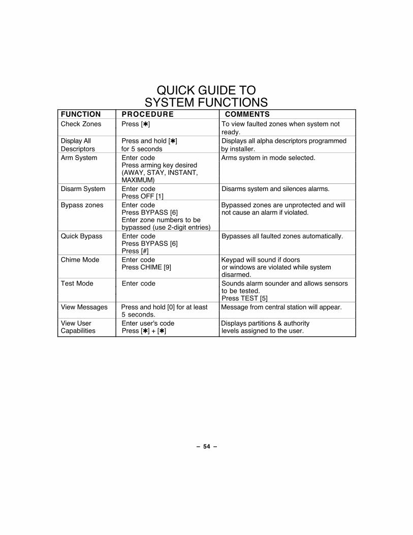
FUNCTION PROCEDURE COMMENTSCheck Zones Press [✱] To view faulted zones when system not
ready.Display All Press and hold [✱] Displays all alpha descriptors programmedDescriptors for 5 seconds by installer.Arm System Enter code Arms system in mode selected.
Press arming key desired (AWAY, STAY, INSTANT,
MAXIMUM)Disarm System Enter code Disarms system and silences alarms.
Press OFF [1]Bypass zones Enter code Bypassed zones are unprotected and will
Press BYPASS [6] not cause an alarm if violated.Enter zone numbers to bebypassed (use 2-digit entries)
Quick Bypass Enter code Bypasses all faulted zones automatically.Press BYPASS [6]Press [#]
Chime Mode Enter code Keypad will sound if doorsPress CHIME [9] or windows are violated while system
disarmed.Test Mode Enter code Sounds alarm sounder and allows sensors
to be tested.Press TEST [5]
View Messages Press and hold [0] for at least Message from central station will appear.5 seconds.
View User Enter user's code Displays partitions & authorityCapabilities Press [✱] + [✱] levels assigned to the user.
Ð 55 Ð
QUICK GUIDE TOSYSTEM FUNCTIONS
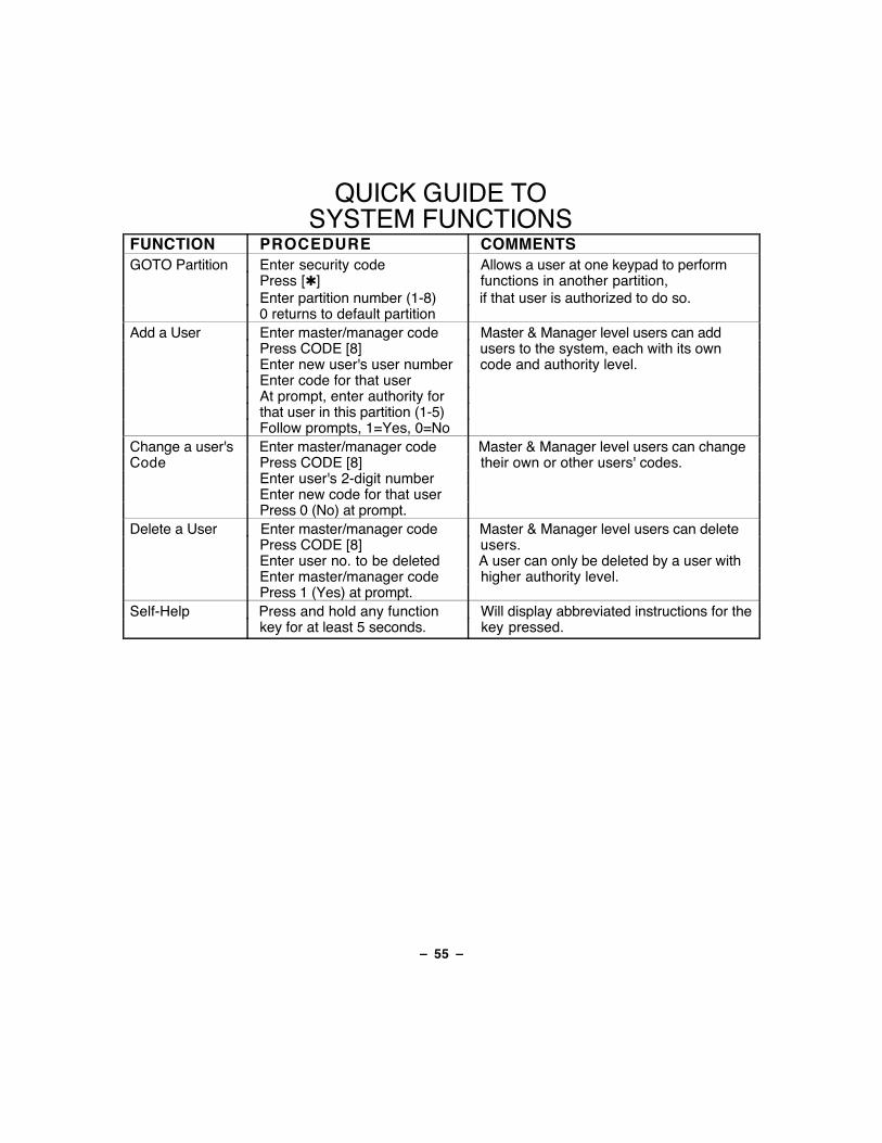
FUNCTION PROCEDURE COMMENTSGOTO Partition Enter security code Allows a user at one keypad to perform
Press [✱] functions in another partition,Enter partition number (1-8) if that user is authorized to do so.0 returns to default partition
Add a User Enter master/manager code Master & Manager level users can addPress CODE [8] users to the system, each with its ownEnter new user's user number code and authority level.Enter code for that userAt prompt, enter authority forthat user in this partition (1-5)Follow prompts, 1=Yes, 0=No
Change a user's Enter master/manager code Master & Manager level users can changeCode Press CODE [8] their own or other users' codes.
Enter user's 2-digit numberEnter new code for that userPress 0 (No) at prompt.
Delete a User Enter master/manager code Master & Manager level users can deletePress CODE [8] users.Enter user no. to be deleted A user can only be deleted by a user withEnter master/manager code higher authority level.Press 1 (Yes) at prompt.
Self-Help Press and hold any function Will display abbreviated instructions for thekey for at least 5 seconds. key pressed.
Ð 56 Ð
SUMMARY OF AUDIBLENOTIFICATION
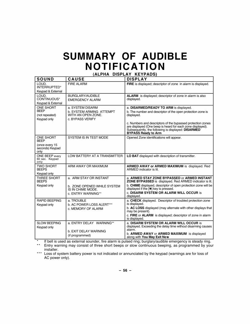
(ALPHA DISPLAY KEYPADS)SOUND CAUSE DISPLAYLOUD,INTERRUPTED*Keypad & External
FIRE ALARM FIRE is displayed; descriptor of zone in alarm is displayed.
LOUD,CONTINUOUS*Keypad & External
BURGLARY/AUDIBLEEMERGENCY ALARM
ALARM is displayed; descriptor of zone in alarm is alsodisplayed.
ONE SHORTBEEP(not repeated)Keypad only
a. SYSTEM DISARMb. SYSTEM ARMING ATTEMPTWITH AN OPEN ZONE.c. BYPASS VERIFY
a. DISARMED/READY TO ARM is displayed.b. The number and descriptor of the open protection zone isdisplayed.
c. Numbers and descriptors of the bypassed protection zonesare displayed (One beep is heard for each zone displayed).Subsequently, the following is displayed: DISARMEDBYPASS Ready to Arm
ONE SHORTBEEP(once every 15seconds) Keypadonly
SYSTEM IS IN TEST MODE Opened Zone identifications will appear.
ONE BEEP every60 sec. Keypadonly
LOW BATTERY AT A TRANSMITTER LO BAT displayed with description of transmitter.
TWO SHORTBEEPSKeypad only
ARM AWAY OR MAXIMUM ARMED AWAY or ARMED MAXIMUM is displayed. RedARMED indicator is lit.
THREE SHORTBEEPSKeypad only
a. ARM STAY OR INSTANT
b. ZONE OPENED WHILE SYSTEMIS IN CHIME MODE.c. ENTRY WARNING**
a. ARMED STAY ZONE BYPASSED or ARMED INSTANTZONE BYPASSED is displayed. Red ARMED indicator is lit.b. CHIME displayed, descriptor of open protection zone will bedisplayed if the [✱] key is pressed.c. DISARM SYSTEM OR ALARM WILL OCCUR isdisplayed.
RAPID BEEPINGKeypad only
a. TROUBLEb. AC POWER LOSS ALERT***c. MEMORY OF ALARM
a. CHECK displayed. Descriptor of troubled protection zoneis displayed.b. AC LOSS displayed (may alternate with other displays thatmay be present).c. FIRE or ALARM is displayed; descriptor of zone in alarmis displayed.
SLOW BEEPINGKeypad only
a. ENTRY DELAY WARNING**
b. EXIT DELAY WARNING(if programmed)
a. DISARM SYSTEM OR ALARM WILL OCCUR isdisplayed. Exceeding the delay time without disarming causesalarm.b. ARMED AWAY or ARMED MAXIMUM is displayedalong with You May Exit Now
* If bell is used as external sounder, fire alarm is pulsed ring; burglary/audible emergency is steady ring.** Entry warning may consist of three short beeps or slow continuous beeping, as programmed by your
installer.*** Loss of system battery power is not indicated or annunciated by the keypad (warnings are for loss of
AC power only).
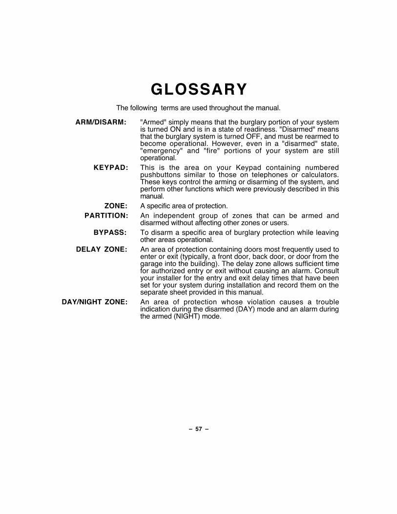
Ð 57 Ð
GLOSSARYThe following terms are used throughout the manual.
ARM/DISARM: "Armed" simply means that the burglary portion of your systemis turned ON and is in a state of readiness. "Disarmed" meansthat the burglary system is turned OFF, and must be rearmed tobecome operational. However, even in a "disarmed" state,"emergency" and "fire" portions of your system are stilloperational.
KEYPAD: This is the area on your Keypad containing numberedpushbuttons similar to those on telephones or calculators.These keys control the arming or disarming of the system, andperform other functions which were previously described in thismanual.
ZONE: A specific area of protection.PARTITION: An independent group of zones that can be armed and
disarmed without affecting other zones or users.BYPASS: To disarm a specific area of burglary protection while leaving
other areas operational.DELAY ZONE: An area of protection containing doors most frequently used to
enter or exit (typically, a front door, back door, or door from thegarage into the building). The delay zone allows sufficient timefor authorized entry or exit without causing an alarm. Consultyour installer for the entry and exit delay times that have beenset for your system during installation and record them on theseparate sheet provided in this manual.
DAY/NIGHT ZONE: An area of protection whose violation causes a troubleindication during the disarmed (DAY) mode and an alarm duringthe armed (NIGHT) mode.
Ð 58 Ð
UL NOTICE: This is a "GRADE A" system."FEDERAL COMMUNICATIONS COMMISSION (FCC) Part 15 STATEMENT"
This equipment has been tested to FCC requirements and has been found acceptable for use. The FCCrequires the following statement for your information:This equipment generates and uses radio frequency energy and if not installed and used properly, that is, instrict accordance with the manufacturer's instructions, may cause interference to radio and televisionreception. It has been type tested and found to comply with the limits for a Class B computing device inaccordance with the specifications in Part 15 of FCC Rules, which are designed to provide reasonableprotection against such interference in a residential installation. However, there is no guarantee thatinterference will not occur in a particular installation. If this equipment does cause interference to radio ortelevision reception, which can be determined by turning the equipment off and on, the user is encouragedto try to correct the interference by one or more of the following measures:
¥ If using an indoor antenna, have a quality outdoor antenna installed.¥ Reorient the receiving antenna until interference is reduced or eliminated.¥ Move the receiver away from the control/communicator.¥ Move the antenna leads away from any wire runs to the control/communicator.¥ Plug the control/communicator into a different outlet so that it and the receiver are on different branch
circuits.If necessary, the user should consult the dealer or an experienced radio/television technician for additionalsuggestions.The user or installer may find the following booklet prepared by the Federal Communications Commissionhelpful: "Interference Handbook"This booklet is available from the U.S. Government Printing Office, Washington, DC 20402.
The user shall not make any changes or modifications to the equipment unless authorized by the InstallationInstructions or User's Manual. Unauthorized changes or modifications could void the user's authority tooperate the equipment.
IN THE EVENT OF TELEPHONE OPERATIONAL PROBLEMSIn the event of telephone operational problems, disconnect the control by removing the plug from the RJ31X(CA38A in Canada) telephone wall jack. We recommend that your certified installer demonstratedisconnecting the phones on installation of the system. Do not disconnect the phone connection inside thecontrol/communicator. Doing so will result in the loss of your phone lines. If the regular phone workscorrectly after the control/communicator has been disconnected from the phone lines, thecontrol/communicator has a problem and should be returned for repair. If upon disconnection of thecontrol/communicator, there is still a problem on the line, notify the telephone company that they have aproblem and request prompt repair service. The user may not under any circumstances (in or out ofwarranty) attempt any service or repairs to the system. It must be returned to the factory or an authorizedservice agency for all repairs.
Ð 59 Ð
"FEDERAL COMMUNICATIONS COMMISSION (FCC) Part 68 NOTICEThis equipment complies with Part 68 of the FCC rules. On the front cover of this equipment is alabel that contains, among other information, the FCC registration number and ringer equivalencenumber (REN) for this equipment. If requested, this information must be provided to thetelephone company.This equipment uses the following jacks:
An RJ31X is used to connect this equipment to the telephone network.The REN is used to determine the quantity of devices which may be connected to the telephoneline. Excessive RENs on the telephone line may result in the devices not ringing in response toan incoming call. In most, but not all areas, the sum of the RENs should not exceed five (5.0). Tobe certain of the number of devices that may be connected to the line, as determined by the totalRENs, contact the telephone company to determine the maximum REN for the calling area.If this equipment causes harm to the telephone network, the telephone company will notify you inadvance that temporary discontinuance of service may be required. If advance notice is notpractical, the telephone company will notify the customer as soon as possible. Also, you will beadvised of your right to file a complaint with the FCC if you believe necessary.The telephone company may make changes in its facilities, equipment, operations, or proceduresthat could affect the operation of the equipment. If this happens, the telephone company willprovide advance notice in order for you to make the necessary modifications in order to maintainuninterrupted service.If trouble is experienced with this equipment, please contact the manufacturer for repair andwarranty information. If the trouble is causing harm to the telephone network, the telephonecompany may request you remove the equipment from the network until the problem is resolved.There are no user serviceable components in this product, and all necessary repairs must bemade by the manufacturer. Other repair methods may invalidate the FCC registration on thisproduct.This equipment cannot be used on telephone company-provided coin service. Connection toParty Line Service is subject to state tariffs.This equipment is hearing-aid compatible.When programming or making test calls to an emergency number, briefly explain to the dispatcherthe reason for the call. Perform such activities in the off-peak hours; such as early morning or lateevening.
Ð 60 Ð
CANADIAN DEPARTMENT OF COMMUNICATIONS(DOC) STATEMENT
NOTICEThe Canadian Department of Communications label identifiescertified equipment. This certification means that theequipment meets certain telecommunications networkprotective, operational and safety requirements. TheDepartment does not guarantee the equipment will operate tothe user's satisfaction.Before installing this equipment, users should ensure that it ispermissible to be connected to the facilities of the localtelecommunications company. The equipment must also beinstalled using an acceptable method of connection. In somecases, the company's inside wiring associated with a singleline individual service may be extended by means of certifiedconnector assembly (telephone extension cord). Thecustomer should be aware that compliance with the aboveconditions may not prevent degradation of service in somesituations.Repairs to certified equipment should be made by anauthorized Canadian maintenance facility designated by thesupplier. Any repairs or alterations made by the user to thisequipment, or equipment malfunctions, may give thetelecommunications company cause to request the user todisconnect the equipment.Users should ensure for their own protection that theelectrical ground connections of the power utility, telephonelines and internal metallic water pipe system, if present, areconnected together. This precaution may be particularlyimportant in rural areas.Caution: User should not attempt to make such connectionsthemselves, but should contact the appropriate electricinspection authority, or electrician, as appropriate.The Load Number (LN) assigned to each terminal devicedenotes the percentage of the total load to be connected to atelephone loop which is used by the device, to preventoverloading. The termination on a loop may consist of anycombination of devices subject only to the requirement thatthe total of the Load Numbers of all the devices does notexceed 100.
AVISL'�tiquette du minist�re des Communications du Canadaidentifie le mat�riel homologu�. Cette �tiquette certifie que lemat�riel est conforme � certaines normes de protection,d'exploitation et de s�curit� des r�seaux det�l�communications. Le minist�re n'assure toutefois pas quele mat�riel fonctionnera � la satisfaction de l'utilisateur.
Avant d'installer ce mat�riel, l'utilisateur doit s'assurer qu'ilest permis de le raccorder aux installations de l'entrepriselocale de t�l�communications. Le mat�riel doit �galement�tre install� en suivant une m�thode accept�e deraccordement. Dans certains cas, les fils int�rieurs del'entreprise utilis�s pour un service individuel � la ligneunique peuvent �tre prolong�s au moyen d'un dispositifhomologu� de raccordement (cordon prolongateurt�l�phonique interne). L'abonn� ne doit pas oublier qu'il estpossible que la conformit� aux conditions �nonc�es ci-dessusn'emp�chet pas la d�gradation du service dans certainessituations. Actuellement, les entreprises det�l�communications ne permettent pas que l'on raccorde leurmat�riel aux prises d'abonn�s, sauf dans les cas precispr�vus par les tarifs particuliers de ces entreprises.
Les r�parations du mat�riel homologu� doivent �treeffectu�es pas un centre d'entretien canadien autoris� d�sign�par le fournisseur. La compagnie de t�l�communications peutdemander � l'utilisateur de d�brancher un appareil � la suitede r�parations ou de modifications effectu�es par l'utilisateurou � cause de mauvais fonctionnement.
Pour sa propre protection, l'utilisateur doit s'assurer que tousles fils de mise en terre de la source d'�nergie �lectrique, deslignes t�l�phoniques de r�seau de conduites d'eau s'il y en a,soient raccord�s ensemble. Cette pr�caution estparticuli�rement importante dans les r�gions rurales.
Avertissement: L'utilisateur ne doit pas tenter de faire cesraccordements lui-m�me; il doit avoir recours � un serviced'inspection des installations �lectriques, ou � un �lectricien,selon le cas.
L'indice de charge (IC) assign� � chaque dispositif terminalpour �viter toute surcharge indique le pourcentage de lacharge totale qui peut �tre raccord� � un circuit t�l�phoniqueboucl� utilis� par ce dispositif. La terminaison du circuitboucl� peut �tre constitu�e de n'importe quelle combinaisonde dispositifs, pourvu que la somme des indices de charge del'ensemble des dispositifs ne d�passe pas 100.
Ð 61 Ð
WARNING!THE LIMITATIONS OF THIS ALARM SYSTEM
While this system is an advanced design security system, it does not offer guaranteed protection againstburglary or fire or other emergency. Any alarm system, whether commercial or residential, is subject tocompromise or failure to warn for a variety of reasons. For example:¥ Intruders may gain access through unprotected openings or have the technical sophistication to bypass
an alarm sensor or disconnect an alarm warning device.¥ Intrusion detectors (e.g. passive infrared detectors), smoke detectors, and many other sensing devices
will not work without power. Battery operated devices will not work without batteries, with dead batteries,or if the batteries are not put in properly. Devices powered solely by AC will not work if their AC powersupply is cut off for any reason, however briefly.
¥ Signals sent by wireless transmitters may be blocked or reflected by metal before they reach the alarmreceiver. Even if the signal path has been recently checked during a weekly test, blockage can occur if ametal object is moved into the path.
¥ A user may not be able to reach a panic or emergency button quickly enough.¥ While smoke detectors have played a key role in reducing residential fire deaths in the United States, they
may not activate or provide early warning for a variety of reasons in as many as 35% of all fires, accordingto data published by the Federal Emergency Management Agency. Some of the reasons smoke detectorsused in conjunction with this System may not work are as follows. Smoke detectors may have beenimproperly installed and positioned. Smoke detectors may not sense fires that start where smoke cannotreach the detectors, such as in chimneys, in walls, or roofs, or on the other side of closed doors. Smokedetectors also may not sense a fire on another level of a residence or building. A second floor detector,for example, may not sense a first floor or basement fire. Moreover, smoke detectors have sensinglimitations. No smoke detector can sense every kind of fire every time. In general, detectors may notalways warn about fires caused by carelessness and safety hazards like smoking in bed, violentexplosions, escaping gas, improper storage of flammable materials, overloaded electrical circuits,children playing with matches, or arson. Depending upon the nature of the fire and/or the locations of thesmoke detectors, the detector, even if it operates as anticipated, may not provide sufficient warning toallow all occupants to escape in time to prevent injury or death.
¥ Passive Infrared Motion Detectors can only detect intrusion within the designed ranges as diagrammed intheir installation manual. Passive Infrared Detectors do not provide volumetric area protection. They docreate multiple beams of protection, and intrusion can only be detected in unobstructed areas covered bythose beams. They cannot detect motion or intrusion that takes place behind walls, ceilings, floors,closed doors, glass partitions, glass doors, or windows. Mechanical tampering, masking, painting orspraying of any material on the mirrors, windows or any part of the optical system can reduce theirdetection ability. Passive Infrared Detectors sense changes in temperature; however, as the ambienttemperature of protected area approaches the temperature range of 90° to 105°F, the detectionperformance can decrease.
Ð 62 Ð
WARNING!THE LIMITATIONS OF THIS ALARM SYSTEM
(continued)¥ Alarm warning devices such as sirens, bells or horns may not alert people or wake up sleepers if they are
located on the other side of closed or partly open doors. If warning devices sound on a different level ofthe residence from the bedrooms, then they are less likely to waken or alert people inside the bedrooms.Even persons who are awake may not hear the warning if the alarm is muffled from a stereo, radio, airconditioner or other appliance, or by passing traffic. Finally, alarm warning devices, however loud, maynot warn hearing-impaired people or waken deep sleepers.
¥ Telephone lines needed to transmit alarm signals from a premises to a central monitoring station may beout of service or temporarily out of service. Telephone lines are also subject to compromise bysophisticated intruders.
¥ Even if the system responds to the emergency as intended, however, occupants may have insufficienttime to protect themselves from the emergency situation. In the case of a monitored alarm system,authorities may not respond appropriately.
¥ This equipment, like other electrical devices, is subject to component failure. Even though this equipmentis designed to last as long as 10 years, the electronic components could fail at any time.
The most common cause of an alarm system not functioning when an intrusion or fire occurs is inadequatemaintenance. This alarm system should be tested weekly to make sure all sensors and transmitters areworking properly.Installing an alarm system may make one eligible for lower insurance rates, but an alarm system is not asubstitute for insurance. Homeowners, property owners and renters should continue to act prudently inprotecting themselves and continue to insure their lives and property.We continue to develop new and improved protection devices. Users of alarm systems owe it to themselvesand their loved ones to learn about these developments.
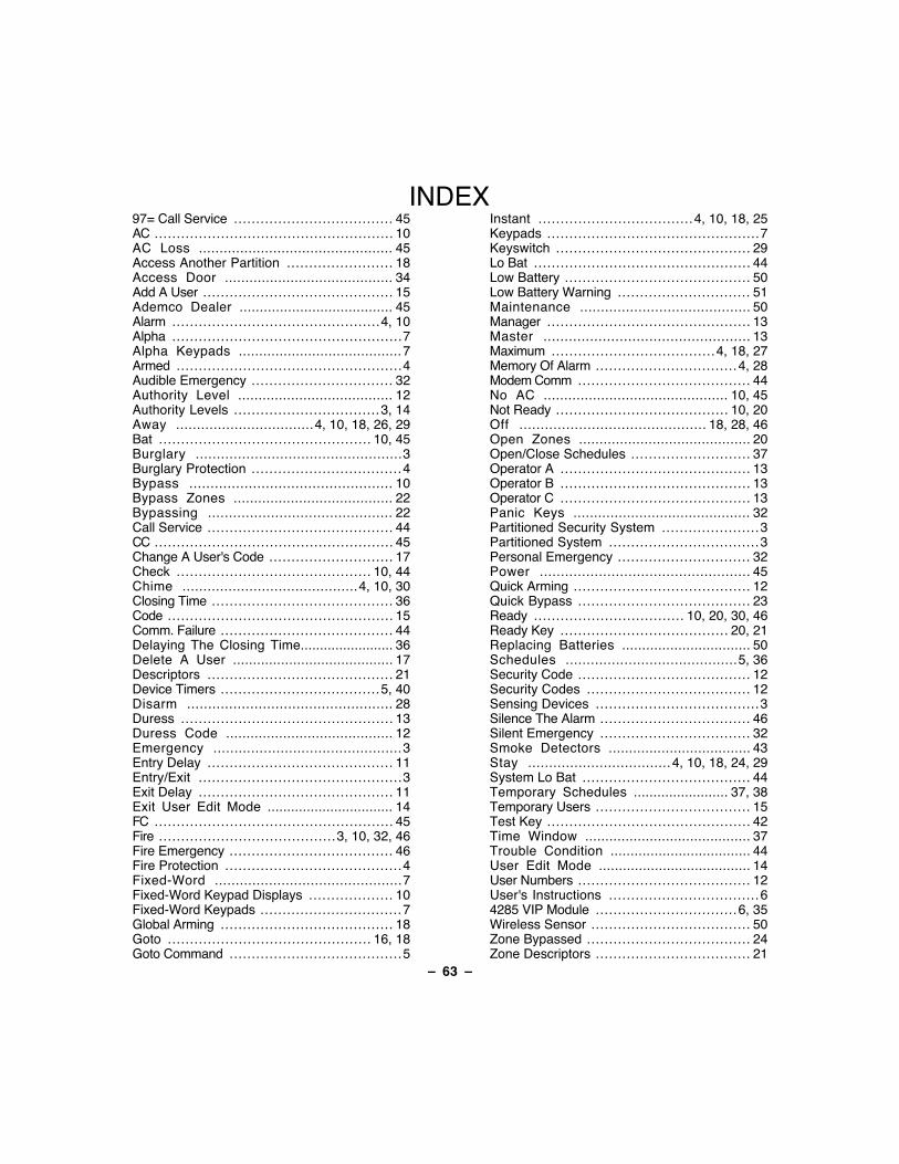
Ð 63 Ð
INDEX97= Call Service .................................... 45AC ...................................................... 10AC Loss ............................................... 45Access Another Partition ........................ 18Access Door ......................................... 34Add A User ........................................... 15Ademco Dealer ...................................... 45Alarm ............................................... 4, 10Alpha .................................................... 7Alpha Keypads ........................................ 7Armed ................................................... 4Audible Emergency ................................ 32Authority Level ...................................... 12Authority Levels ................................. 3, 14Away ................................. 4, 10, 18, 26, 29Bat ................................................ 10, 45Burglary ................................................. 3Burglary Protection .................................. 4Bypass ................................................ 10Bypass Zones ....................................... 22Bypassing ............................................ 22Call Service .......................................... 44CC ...................................................... 45Change A User's Code ............................ 17Check ............................................ 10, 44Chime .......................................... 4, 10, 30Closing Time ......................................... 36Code ................................................... 15Comm. Failure ....................................... 44Delaying The Closing Time........................ 36Delete A User ........................................ 17Descriptors .......................................... 21Device Timers .................................... 5, 40Disarm ................................................. 28Duress ................................................ 13Duress Code ......................................... 12Emergency ............................................. 3Entry Delay .......................................... 11Entry/Exit .............................................. 3Exit Delay ............................................ 11Exit User Edit Mode ................................ 14FC ...................................................... 45Fire ........................................ 3, 10, 32, 46Fire Emergency ..................................... 46Fire Protection ........................................ 4Fixed-Word ............................................. 7Fixed-Word Keypad Displays ................... 10Fixed-Word Keypads ................................ 7Global Arming ....................................... 18Goto .............................................. 16, 18Goto Command ....................................... 5
Instant ................................... 4, 10, 18, 25Keypads ................................................ 7Keyswitch ............................................ 29Lo Bat ................................................. 44Low Battery .......................................... 50Low Battery Warning .............................. 51Maintenance ......................................... 50Manager .............................................. 13Master ................................................. 13Maximum ..................................... 4, 18, 27Memory Of Alarm ................................ 4, 28Modem Comm ....................................... 44No AC ............................................. 10, 45Not Ready ....................................... 10, 20Off ............................................ 18, 28, 46Open Zones .......................................... 20Open/Close Schedules ........................... 37Operator A ........................................... 13Operator B ........................................... 13Operator C ........................................... 13Panic Keys ........................................... 32Partitioned Security System ...................... 3Partitioned System .................................. 3Personal Emergency .............................. 32Power .................................................. 45Quick Arming ........................................ 12Quick Bypass ....................................... 23Ready .................................. 10, 20, 30, 46Ready Key ...................................... 20, 21Replacing Batteries ................................ 50Schedules ......................................... 5, 36Security Code ....................................... 12Security Codes ..................................... 12Sensing Devices ..................................... 3Silence The Alarm .................................. 46Silent Emergency .................................. 32Smoke Detectors ................................... 43Stay .................................. 4, 10, 18, 24, 29System Lo Bat ...................................... 44Temporary Schedules ........................ 37, 38Temporary Users ................................... 15Test Key .............................................. 42Time Window ......................................... 37Trouble Condition ................................... 44User Edit Mode ...................................... 14User Numbers ....................................... 12User's Instructions .................................. 64285 VIP Module ................................ 6, 35Wireless Sensor .................................... 50Zone Bypassed ..................................... 24Zone Descriptors ................................... 21

àN6020-2säN6020-2 Rev B 4/99
ADEMCO ONE YEAR LIMITED WARRANTYAlarm Device Manufacturing Company, a Division of Pittway Corporation, and its divisions, subsidiaries andaffiliates ("Seller"), 165 Eileen Way, Syosset, New York 11791, warrants its security equipment (the"product") to be free from defects in materials and workmanship for one year from date of original purchase,under normal use and service. Seller's obligation is limited to repairing or replacing, at its option, free ofcharge for parts, labor, or transportation, any product proven to be defective in materials or workmanshipunder normal use and service. Seller shall have no obligation under this warranty or otherwise if the productis altered or improperly repaired or serviced by anyone other than the Seller. In case of defect, contact thesecurity professional who installed and maintains your security equipment or the Seller for product repair.This one year Limited Warranty is in lieu of all other express warranties, obligations or liabilities. THERE ARENO EXPRESS WARRANTIES, WHICH EXTEND BEYOND THE FACE HEREOF. ANY IMPLIEDWARRANTIES, OBLIGATIONS OR LIABILITIES MADE BY SELLER IN CONNECTION WITH THISPRODUCT, INCLUDING ANY IMPLIED WARRANTY OF MERCHANTABILITY, OR FITNESS FOR APARTICULAR PURPOSE OR OTHERWISE, ARE LIMITED IN DURATION TO A PERIOD OF ONE YEARFROM THE DATE OF ORIGINAL PURCHASE. ANY ACTION FOR BREACH OF ANY WARRANTY, INCLUDINGBUT NOT LIMITED TO ANY IMPLIED WARRANTY OF MERCHANTABILITY, MUST BE BROUGHT WITHIN 12MONTHS FROM DATE OF ORIGINAL PURCHASE. IN NO CASE SHALL SELLER BE LIABLE TO ANYONEFOR ANY CONSEQUENTIAL OR INCIDENTAL DAMAGES FOR BREACH OF THIS OR ANY OTHERWARRANTY, EXPRESS OR IMPLIED, OR UPON ANY OTHER BASIS OF LIABILITY WHATSOEVER, EVENIF THE LOSS OR DAMAGE IS CAUSED BY THE SELLER'S OWN NEGLIGENCE OR FAULT. Some states donot allow limitation on how long an implied warranty lasts or the exclusion or limitation of incidental orconsequential damages, so the above limitation or exclusion may not apply to you.Seller does not represent that the product may not be compromised or circumvented; that the product willprevent any personal injury or property loss by burglary, robbery, fire or otherwise; or that the product will inall cases provide adequate warning or protection. Buyer understands that a properly installed andmaintained alarm may only reduce the risk of a burglary, robbery, fire or other events occurring withoutproviding an alarm, but it is not insurance or a guarantee that such will not occur or that there will be nopersonal injury or property loss as a result. CONSEQUENTLY, SELLER SHALL HAVE NO LIABILITY FORANY PERSONAL INJURY, PROPERTY DAMAGE OR OTHER LOSS BASED ON A CLAIM THE PRODUCTFAILED TO GIVE WARNING. HOWEVER, IF SELLER IS HELD LIABLE, WHETHER DIRECTLY ORINDIRECTLY, FOR ANY LOSS OR DAMAGE ARISING UNDER THIS LIMITED WARRANTY OR OTHERWISE,REGARDLESS OF CAUSE OR ORIGIN, SELLER'S MAXIMUM LIABILITY SHALL NOT IN ANY CASEEXCEED THE PURCHASE PRICE OF THE PRODUCT, WHICH SHALL BE THE COMPLETE AND EXCLUSIVEREMEDY AGAINST SELLER. This warranty gives you specific legal rights, and you may also have otherrights which vary from state to state. No increase or alteration, written or verbal, to this warranty isauthorized.
A DIVISION OF PITTWAY CORPORATION165 Eileen Way, Syosset, New York 11791
Copyright © 1995 PITTWAY CORPORATION
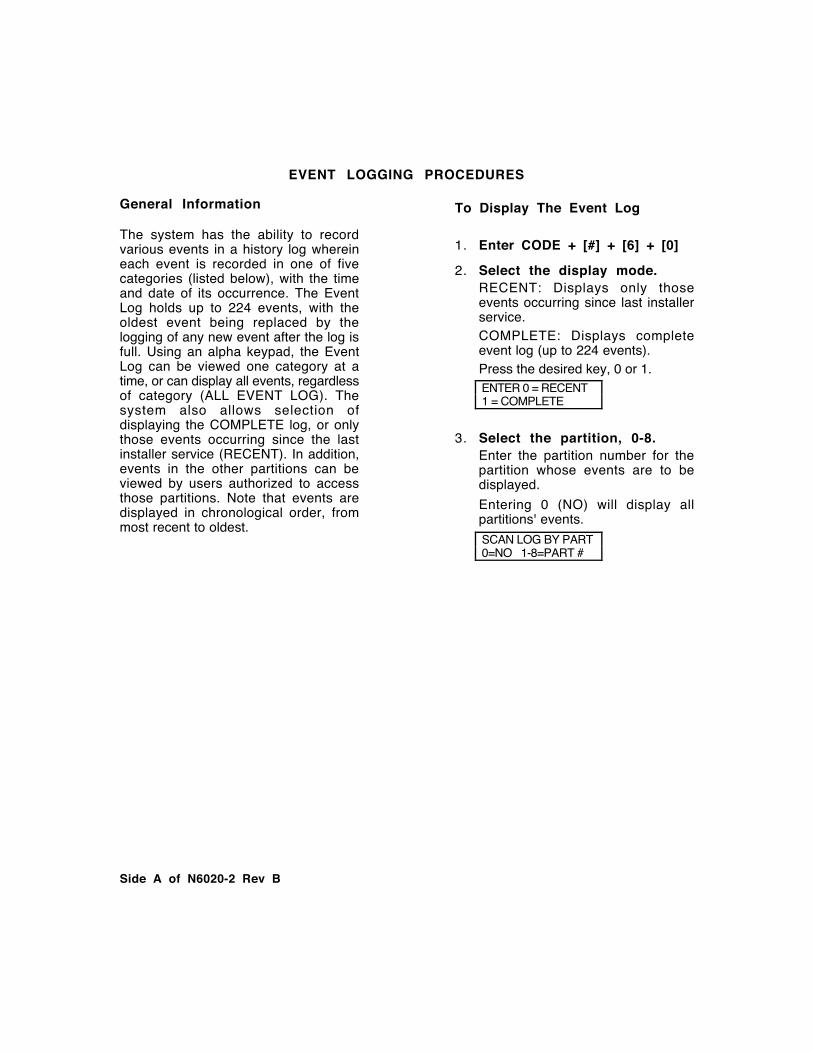
Side A of N6020-2 Rev B
EVENT LOGGING PROCEDURES
General Information
The system has the ability to recordvarious events in a history log whereineach event is recorded in one of fivecategories (listed below), with the timeand date of its occurrence. The EventLog holds up to 224 events, with theoldest event being replaced by thelogging of any new event after the log isfull. Using an alpha keypad, the EventLog can be viewed one category at atime, or can display all events, regardlessof category (ALL EVENT LOG). Thesystem also allows selection ofdisplaying the COMPLETE log, or onlythose events occurring since the lastinstaller service (RECENT). In addition,events in the other partitions can beviewed by users authorized to accessthose partitions. Note that events aredisplayed in chronological order, frommost recent to oldest.
To Display The Event Log
1. Enter CODE + [#] + [6] + [0]
2. Select the display mode.RECENT: Displays only thoseevents occurring since last installerservice.COMPLETE: Displays completeevent log (up to 224 events).Press the desired key, 0 or 1. ENTER 0 = RECENT 1 = COMPLETE
3. Select the partition, 0-8.Enter the partition number for thepartition whose events are to bedisplayed.
Entering 0 (NO) will display allpartitions' events.
SCAN LOG BY PART 0=NO 1-8=PART #
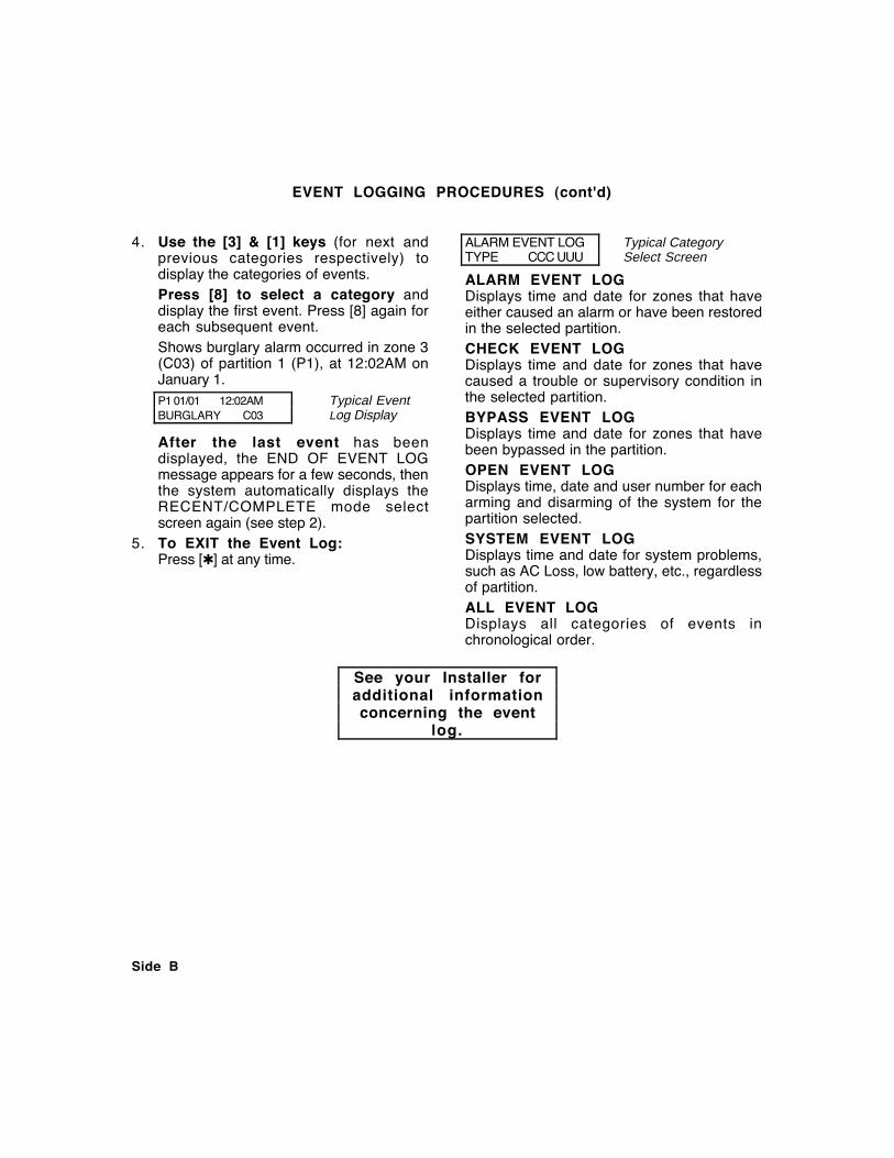
Side B
EVENT LOGGING PROCEDURES (cont'd)
4. Use the [3] & [1] keys (for next andprevious categories respectively) todisplay the categories of events.Press [8] to select a category anddisplay the first event. Press [8] again foreach subsequent event.Shows burglary alarm occurred in zone 3(C03) of partition 1 (P1), at 12:02AM onJanuary 1.P1 01/01 12:02AM Typical EventBURGLARY C03 Log Display
After the last event has beendisplayed, the END OF EVENT LOGmessage appears for a few seconds, thenthe system automatically displays theRECENT/COMPLETE mode selectscreen again (see step 2).
5. To EXIT the Event Log:Press [✱] at any time.
ALARM EVENT LOG Typical CategoryTYPE CCC UUU Select Screen
ALARM EVENT LOGDisplays time and date for zones that haveeither caused an alarm or have been restoredin the selected partition.CHECK EVENT LOGDisplays time and date for zones that havecaused a trouble or supervisory condition inthe selected partition.BYPASS EVENT LOGDisplays time and date for zones that havebeen bypassed in the partition.OPEN EVENT LOGDisplays time, date and user number for eacharming and disarming of the system for thepartition selected.SYSTEM EVENT LOGDisplays time and date for system problems,such as AC Loss, low battery, etc., regardlessof partition.ALL EVENT LOGDisplays all categories of events inchronological order.
See your Installer foradditional informationconcerning the event
log.