
Vision-Guided Flight Stability and Control for Micro Air ... · Vision-Guided Flight Stability and...
7
Vision-Guided Flight Stability and Control for Micro Air Vehicles Scott M. Ettinger 1,2 Michael C. Nechyba 1 Peter G. Ifju 2 Martin Waszak 3 [email protected] [email protected] [email protected] [email protected] 1 Department of Electrical and Computer Engineering University of Florida, Gainesville, FL 32611-6200 2 Department of Aerospace Engineering, Mechanics and Engineering University of Florida, Gainesville, FL 32611-6250 3 Dynamics and Control Branch, NASA Langley Research Center MS 132, Hampton, VA 23681-2199 Abstract Substantial progress has been made recently towards design- ing, building and test-flying remotely piloted Micro Air Vehicles (MAVs) and small UAVs. We seek to complement this progress in overcoming the aerodynamic obstacles to flight at very small scales with a vision-guided flight stability and autonomy system, based on a robust horizon detection algorithm. In this paper, we first motivate the use of computer vision for MAV autonomy, ar- guing that given current sensor technology, vision may be the only practical approach to the problem. We then describe our sta- tistical vision-based horizon detection algorithm, which has been demonstrated at 30Hz with over 99.9% correct horizon identifica- tion. Next, we develop robust schemes for the detection of extreme MAV attitudes, where no horizon is visible, and for the detection of horizon estimation errors, due to external factors such as video transmission noise. Finally, we discuss our feedback controller for self-stabilized flight, and report results on vision-based auton- omous flights of duration exceeding ten minutes. 1. Introduction Ever since humankind’s first powered flight, research efforts have continually pushed the envelope to create flying machines that are faster and/or larger than ever before. Now, however, there is an effort to design aircraft at the other, largely unexplored end of the spectrum, where the desire for portable, low-altitude aerial surveillance has driven the development and testing of aircraft that are as small and slow as the laws of aerodynamics will permit — in other words, on the scale and in the operational range of small birds. Vehicles in this class of small-scale aircraft are known as Micro Air Vehicles or MAVs. Equipped with small video cameras and transmitters, MAVs have great potential for surveillance and monitoring tasks in areas either too remote or too dangerous to send human scouts. Opera- tional MAVs will enable a number of important missions, includ- ing chemical/radiation spill monitoring, forest-fire reconnaissance, visual monitoring of volcanic activity, surveys of natural disaster areas, and even inexpensive traffic and accident monitoring. Additional on-board sensors can further augment MAV mission profiles to include, for example, airborne chemical analysis. In the military, one of the primary roles for MAVs will be as small-unit battlefield surveillance agents, where MAVs can act as an extended set of eyes in the sky for military units in the field. This use of MAV technology is intended to reduce the risk to military personnel and has, perhaps, taken on increased impor- tance in light of the U.S.’s new war on terrorism, where special operations forces are playing a crucial role. Virtually undetectable from the ground, MAVs could penetrate potential terrorist camps and other targets prior to any action against those targets, signifi- cantly raising the chance for overall mission success. Researchers in the Aerospace Engineering Department at the University of Florida have established a long track record in de- signing, building and test-flying (remotely human-piloted) practi- cal MAVs [6-8,11]. For example, Figure 1 shows one of our recently developed MAVs as well as a small UAV design. While much progress has been made in the design of ever smaller MAVs by researchers at UF and others in the past five years, significantly less progress has been made towards equipping these MAVs with autonomous capabilities that could significantly enhance the util- ity of MAVs for a wide range of missions. The first step in achieving such MAV autonomy is basic sta- bility and control. Here, we present such a flight stability and con- trol system, based on vision processing of video from a camera on-board our MAVs. In this paper, we first motivate the use of computer vision for such a control system, and describe our vi- sion-based horizon detection algorithm, which forms the basis of the flight stability system presented here. Next, we address real- time control issues in the flight stability system, including ex- treme attitude detection (i.e. no horizon in the image), confidence measures for the detected horizon estimates, and filtering of hori- zon estimates over time. Finally we report some results of self- stabilized MAV flights over the campus of the University of Flor- ida and over Fort Campbell, Kentucky. 2. Horizon detection MAV flight stability and control presents some difficult chal- lenges. The low moments of inertia of MAVs make them vulner- able to rapid angular accelerations, a problem further complicated by the fact that aerodynamic damping of angular rates decreases with a reduction in wingspan. Another potential source of insta- bility for MAVs is the relative magnitudes of wind gusts, which are much higher at the MAV scale than for larger aircraft. In fact, wind gusts can typically be equal to or greater than the forward airspeed of the MAV itself. Thus, an average wind gust can im- mediately affect a dramatic change in the vehicle’s flight path.
Transcript of Vision-Guided Flight Stability and Control for Micro Air ... · Vision-Guided Flight Stability and...
Vision-Guided Flight Stability and Control for Micr o Air Vehicles
Scott M. Ettinger
1,2
Michael C. Nechyba
1
Peter G. Ifju
2
Martin Waszak
3
[email protected] [email protected] [email protected] [email protected]
1
Department of Electrical and Computer EngineeringUniversity of Florida, Gainesville, FL 32611-6200
2
Department of Aerospace Engineering, Mechanics and EngineeringUniversity of Florida, Gainesville, FL 32611-6250
3
Dynamics and Control Branch, NASA Langley Research CenterMS 132, Hampton, VA 23681-2199
Abstract
Substantial progress has been made recently towards design-ing, building and test-flying remotely piloted Micro Air Vehicles(MAVs) and small UAVs. We seek to complement this progress inovercoming the aerodynamic obstacles to flight at very smallscales with a
vision-guided flight stability and autonomy system
,based on a robust horizon detection algorithm. In this paper, wefirst motivate the use of computer vision for MAV autonomy, ar-guing that given current sensor technology, vision may be theonly practical approach to the problem. We then describe our sta-tistical vision-based horizon detection algorithm, which has beendemonstrated at 30Hz with over 99.9% correct horizon identifica-tion. Next, we develop robust schemes for the detection of extremeMAV attitudes, where no horizon is visible, and for the detectionof horizon estimation errors, due to external factors such as videotransmission noise. Finally, we discuss our feedback controllerfor self-stabilized flight, and report results on vision-based auton-omous flights of duration exceeding ten minutes.
1. Intr oduction
Ever since humankind’s first powered flight, research effortshave continually pushed the envelope to create flying machinesthat are faster and/or larger than ever before. Now, however, thereis an effort to design aircraft at the other, largely unexplored endof the spectrum, where the desire for portable, low-altitude aerialsurveillance has driven the development and testing of aircraftthat are as small and slow as the laws of aerodynamics will permit— in other words, on the scale and in the operational range ofsmall birds. Vehicles in this class of small-scale aircraft areknown as
Micro Air Vehicles
or
MAVs
.Equipped with small video cameras and transmitters, MAVs
have great potential for surveillance and monitoring tasks in areaseither too remote or too dangerous to send human scouts. Opera-tional MAVs will enable a number of important missions, includ-ing chemical/radiation spill monitoring, forest-firereconnaissance, visual monitoring of volcanic activity, surveys ofnatural disaster areas, and even inexpensive traffic and accidentmonitoring. Additional on-board sensors can further augmentMAV mission profiles to include, for example, airborne chemicalanalysis. In the military, one of the primary roles for MAVs willbe as small-unit battlefield surveillance agents, where MAVs canact as an extended set of eyes in the sky for military units in the
field. This use of MAV technology is intended to reduce the riskto military personnel and has, perhaps, taken on increased impor-tance in light of the U.S.’s new war on terrorism, where specialoperations forces are playing a crucial role. Virtually undetectablefrom the ground, MAVs could penetrate potential terrorist campsand other targets prior to any action against those targets, signifi-cantly raising the chance for overall mission success.
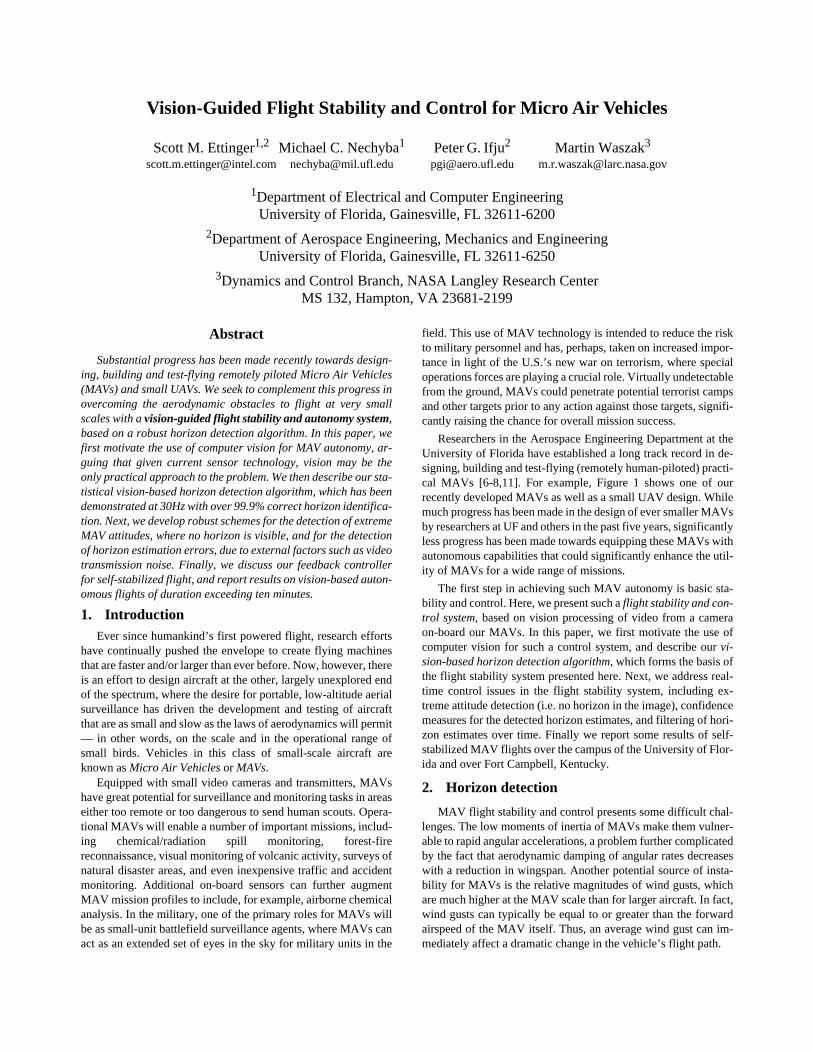
Researchers in the Aerospace Engineering Department at theUniversity of Florida have established a long track record in de-signing, building and test-flying (remotely human-piloted) practi-cal MAVs [6-8,11]. For example, Figure 1 shows one of ourrecently developed MAVs as well as a small UAV design. Whilemuch progress has been made in the design of ever smaller MAVsby researchers at UF and others in the past five years, significantlyless progress has been made towards equipping these MAVs withautonomous capabilities that could significantly enhance the util-ity of MAVs for a wide range of missions.
The first step in achieving such MAV autonomy is basic sta-bility and control. Here, we present such a
flight stability and con-trol system
, based on vision processing of video from a cameraon-board our MAVs. In this paper, we first motivate the use ofcomputer vision for such a control system, and describe our
vi-sion-based horizon detection algorithm
, which forms the basis ofthe flight stability system presented here. Next, we address real-time control issues in the flight stability system, including ex-treme attitude detection (i.e. no horizon in the image), confidencemeasures for the detected horizon estimates, and filtering of hori-zon estimates over time. Finally we report some results of self-stabilized MAV flights over the campus of the University of Flor-ida and over Fort Campbell, Kentucky.
2. Horizon detection
MAV flight stability and control presents some difficult chal-lenges. The low moments of inertia of MAVs make them vulner-able to rapid angular accelerations, a problem further complicatedby the fact that aerodynamic damping of angular rates decreaseswith a reduction in wingspan. Another potential source of insta-bility for MAVs is the relative magnitudes of wind gusts, whichare much higher at the MAV scale than for larger aircraft. In fact,wind gusts can typically be equal to or greater than the forwardairspeed of the MAV itself. Thus, an average wind gust can im-mediately affect a dramatic change in the vehicle’s flight path.
Birds, the biological counterpart of mechanical MAVs, can of-fer some important insights into how one may best be able toovercome these problems. In studying the nervous system ofbirds, one basic observation holds true for virtually all of the thou-sands of different bird species:
Birds rely heavily on sharp eyesand vision to guide almost every aspect of their behavior
[2-5,12].Biological systems, while forceful evidence of the importance ofvision in flight, do not, however, in and of themselves warrant acomputer-vision based approach to MAV autonomy. Other equal-ly important factors guide this decision as well. Perhaps most crit-ical, the technologies used in rate and acceleration sensors onlarger aircraft are not currently available at the MAV scale. It hasproven very difficult, if not impossible, to scale these technolo-gies down to meet the very low payload requirements of MAVs.While a number of sensor technologies do currently exist in smallenough packages to be used in MAV systems, these small sensorshave sacrificed accuracy for reduced size and weight. Even if suf-ficient rate and acceleration sensors did exist, however, their useon MAVs may still not be the best allocation of payload capacity.For many potential MAV missions, vision may be the only prac-tical sensor than can achieve required and/or desirable autono-mous behaviors. Furthermore, given that surveillance has beenidentified as one their primary missions, MAVs must necessarilybe equipped with on-board imaging sensors, such as cameras orinfrared arrays. Thus, computer-vision techniques exploit alreadypresent sensors, rich in information content, to significantly ex-tend the capabilities of MAVs, without increasing the MAV’s re-quired payload.
2.1 Horizon-detection algorithm
Fundamentally, flight stability and control requires measure-ment of the MAV’s angular orientation. While for larger aircraftthis is typically estimated through the integration of the aircraft’sangular rates or accelerations, a vision-based system can directlymeasure the aircraft’s orientation with respect to the ground. Thetwo degrees of freedom critical for stability — the
bank angle
and the
pitch angle
1
— can be derived from a line correspond-ing to the horizon as seen from a forward facing camera on the air-craft. Therefore, we have developed a vision-based horizon-detection algorithm that lies at the core of our flight stability sys-tem, and which rests on two basic assumptions: (1) the horizon
line will appear as approximately a straight line in the image; and(2) the horizon line will separate the image into two regions thathave different appearance; in other words, sky pixels will lookmore like other sky pixels and less like ground pixels, and viceversa. The question now is how to transform these basic assump-tions into a workable algorithm.
The first assumption — namely, that the horizon line will ap-pear as a straight line in the image — reduces the space of all pos-sible horizons to a two-dimensional search in line-parameterspace. For each possible line in that two-dimensional space, wemust be able to tell how well that particular line agrees with thesecond assumption — namely that the correct horizon line willseparate the image into two regions that have different appear-ance. Thus our algorithm can be divided into two functional parts:(1) for any given hypothesized horizon line, the definition of anoptimization criterion that measures agreement with the secondassumption, and (2) the means for conducting an efficient searchthrough all possible horizons in two-dimensional parameter spaceto maximize that optimization criterion.
2.2 Optimization criterion
For our current algorithm we choose color, as defined in RGBspace, as our measure of appearance. In making this choice, we donot discount the potential benefit of other appearance measures,such as texture; however, in exploring possible feature extractionmethods, we believe that simple appearance models ought to pre-cede pursuit of more advanced feature extraction methods.
For any given hypothesized horizon line, we label pixelsabove the line as sky, and pixels below the line as ground. Let usdenote all hypothesized sky pixels as,
, , (1)
where denotes the red channel value, denotes the greenchannel value and denotes the blue channel value of the thsky pixel, and let us denote all hypothesized ground pixels as,
, . (2)
Given these pixel groupings, we want to quantify the assumptionthat sky pixels will look similar to other sky pixels, and thatground pixels will look similar to other ground pixels. One mea-sure of this is the degree of variance exhibited by each distribu-tion. Therefore, we propose the following optimization criterion:
1. Instead of the pitch angle , we actually recover the closely related pitch percentage , which measures the percentage of the image above the horizon line.
Fig. 1: (a) six-inch UF MAV, (b) six-inch UF MAV in flight with view through its on-board camera, and (c) 24-inch small UAV.
(a) (b) (c)
φ
θ
θ
σ
x
is
r
is
g
is
b
is
=
i
1
…
n
s
, ,{ }∈
r
is
g
is
b
is
i
x
ig
r
ig
g
ig
b
ig
=
i
1
…
n
g
, ,{ }∈
(3)
based on the covariance matrices and of the two pixel dis-tributions,
(4)
(5)
where,
, , (6)
and and , , denote the eigenvalues of and respectively. For video frames with sufficient color information, the deter-
minant terms in (3) will dominate, since the determinant is a prod-uct of the eigenvalues; however, for cameras with poor colorcharacteristics or video frames exhibiting loss of color informa-tion due to video transmission noise, the covariance matrices maybecome ill-conditioned or singular. When this is the case, thesum-of-eigenvalues terms will become controlling instead, sincethe determinants will evaluate to zero for all possible horizonlines.
Assuming that the means of the actual sky and ground distri-butions are distinct (a requirement for a detectable horizon, evenfor people), the line that best separates the two regions should ex-hibit the lowest variance from the mean. If the hypothesized hori-zon line is incorrect, some ground pixels will be mistakenlygrouped with sky pixels and vice versa. The incorrectly groupedpixels will lie farther from each mean, consequently increasingthe variance of the two distributions. Moreover, the incorrectlygrouped pixels will skew each mean vector slightly, contributingfurther to increased variance in the distributions.
2.3 Maximizing the optimization criterion
Given the optimization criterion in equation (3), which al-lows us to evaluate any given hypothesized horizon line, we mustnow find that horizon line which maximizes . As we have statedpreviously, this boils down to a search in two-dimensional lineparameter space, where our choice of parameters are the bank an-gle and pitch percentage with ranges,
and . (7)
To meet real-time processing constraints
1
, we adopt a two stepapproach in our search through line-parameter space. We firstevaluate at discretized parameter values in the ranges specifiedby (7) on down-sampled images with resolution . Then,we fine-tune the coarse parameter estimate from the previous stepthrough a bisection-like search about the initial guess on a higherresolution image ( , , ). Further detailson the search part of the algorithm may be found in [4].
Thus, we can summarize the horizon-detection algorithm asfollows. Given a video frame at resolution:
1. Down-sample the image to , where , .
2. Evaluate on the down-sampled image for line parameters, where,
, , (8)
3. Select such that,
, . (9)
4. Use bisection search on the high-resolution image to fine-tunethe values of .
At this point, the reader might be wondering whether a fullsearch of the line-parameter space (even at coarse resolution) isreally required once flying, since the horizon at the current timestep should be very close to the horizon at the previous time step;perhaps speed improvements could be made by limiting this ini-tial search. There is, however, at least one very important reasonfor not limiting the initial search — namely robustness to singleframe errors in horizon estimation. Assume, for example, that thealgorithm makes an error in the horizon estimate at time ; then,at time , a limited search could permanently lock us into theinitial incorrect horizon estimate, with potentially catastrophic re-sults. A full, coarse search of line parameter space, on the otherhand, guards against cascading failures due to single-frame errors.
2.4 Horizon-detection examples
Figure 2 illustrates several examples of the horizon-detectionalgorithm at work, while Figure 3 illustrates a more detailed ex-ample plotting as a function of the bank angle and pitch per-centage, and the consequent classification of pixels as sky andground in RGB space. Additional examples and videos can befound at http://mil.ufl.edu/~nechyba/mav. Our horizon-detectionalgorithm has been demonstrated to run at 30 Hz on a 900 MHzx86 processor with a down-sampled image of
resolution, a search resolution of ,and a final image of resolution. If suchcomputing power is not available, we have shown only slightlyreduced performance at values as low as ,
and .
At different times of the day, and under both fair and cloudyconditions, we have gathered hours of video on-board our MAV,flying under manual control over terrain that includes roads,buildings large and small, meadows, wooded areas, and a lake.For these data, our horizon-detection algorithm correctly identi-fies the horizon in over 99.9% of cases.
3. Flight stability and control
In this section, we extend the basic horizon-detection algo-rithm developed in the previous section to
real-time horizontracking
. Below, we consider the following important issues: (1)extreme attitude detection, (2) error detection in horizon estima-tion, (3) filtering of the horizon estimate over time, and (4) basicfeedback control and stabilization of the MAV.
1. See [4] for details on additional algorithmic optimizations.
J
1
Σ
s
Σ
g
λ
1
s
λ
2
s
λ
3
s
+ +
( )
2
λ
1
g
λ
2
g
λ
3
g
+ +
( )
2
+ + +------------------------------------------------------------------------------------------------------------------=
Σ
s
Σ
g
Σ
s
1
n
s
1
–
( )
------------------
x
is
µ
s
–
( )
x
is
µ
s
–
( )
T
i
1
=
n
s
∑
=
Σ
g
1
n
g
1
–
( )
-------------------
x
ig
µ
g
–
( )
x
ig
µ
g
–
( )
T
i
1
=
n
g
∑
=
µ
s
1
n
s
-----
x
is
i
1
=
n
s
∑
=
µ
g
1
n
g
-----
x
ig
i
1
=
n
g
∑
=
λ
is
λ
ig
i
1 2 3
, ,{ }∈
Σ
s
Σ
g
J
J
φ
σ
φ π
–
2
⁄ π
2
⁄,[ ]∈
σ
0% 100%
,[ ]∈
J
X
L
Y
L
×
X
H
Y
H
×
X
L
X
H
«
Y
L
Y
H
«
X
H
Y
H
×
X
L
Y
L
×
X
L
X
H
«
Y
L
Y
H
«
J
φ
i
σ
j
,( )
φ
i
σ
j
,( )
i
π
n
-----
π
2
---–
100
jn
---
,
=
0
i n
≤ ≤
0
j n
≤ ≤
φ∗ σ∗,( )
J
φ φ∗
=
σ, σ∗
=
J
φ φ
i
=
σ, σ
j
=
≥
i j
,∀
φ∗ σ∗,( )
t
t
1
+
J
X
L
Y
L
×
80 60
×
=
n
36
=
X
H
Y
H
×
320 240
×
=
X
L
Y
L
×
40 30
×
=
n
12
=
X
H
Y
H
×
160 120
×
=

3.1 Extreme attitude detection
One of the implicit assumptions of the horizon detection algo-rithm is that there will always be a horizon in the images from theforward looking camera on board the MAV. In real-time controlof the MAV, the MAV may, however, encounter times when novisible horizon appears in the image, if, for example, a gust ofwind forces the nose of the aircraft too far up or down. Such casescannot simply be ignored; if the aircraft is heading straight to-wards the ground, no horizon will be visible in the camera image,yet the control system will certainly be required to take action tosave the MAV from certain and possibly catastrophic crashing.
It is desired then, to be able to detect instances when the hori-zon is not in view of the camera, and if so to determine what ac-tion to take in order to bring the horizon back into view. There are
two valuable sources of information which we can draw on to de-tect these types of extreme attitudes: (1) recent appearance of thesky and ground from previous time steps, and (2) recent locationof the horizon line from previous time steps. For example, if thehorizon line was recently estimated to lie near the top of the im-age, it is logical that a subsequent image without a horizon line ismost likely a view of the ground. We can use these two pieces ofinformation to quantitatively determine if the horizon line existsin the image and if not, to determine whether we are looking at thesky or the ground.
Using the statistics already computed as part of the horizon-detection algorithm, we can model the appearance of the sky andground over a recent time history of the MAV’s flight. Our gen-eral approach for detection of extreme attitudes keeps running sta-
Fig. 2: Various horizon-detection examples under different lighting conditions (sunny and cloudy), and with varying degrees of video transmission noise. For each example, the yellow line indicates the algorithm’s horizon estimate.
Fig. 3: (a) original image, (b) optimization criterion as a function of bank angle and pitch percentage and (c) resulting classification of sky and ground pixels in RGB space.
J
φσ
RedGreen
Blue
(b) (c)(a)

tistical models for both the sky and ground from previous frames,where horizon lines were detected with a high degree of confi-dence. With each new frame, the result of the horizon detectionalgorithm can be checked by comparing the sky and ground mod-els for the current frame with the computed, time-dependent sta-tistical models for sky and ground. If the distributions on eitherside of the line in the current frame both appear to be more similarto the known ground distribution, then it would appear that theaircraft is pointing towards the ground. Conversely, if they bothmatch the sky better, then it is advisable to nose downward. Inter-estingly, if the sky in the current frame matches the ground modelwhile the ground in the current frame matches better with the skymodel, we can detect situations where the plane is flying upsidedown.
One additional piece of information is required to implementthe extreme attitude detection scheme, namely, a time history ofthe horizon line estimate. For the purposes of detecting extremeattitudes, we are most concerned with a recent history of the pitchpercentage , the percentage of the image below the horizon line.One measure of that history is a running average of the pitchpercentage over the previous ten frames.
Upon startup of the system, the camera is assumed to be ori-ented such that the horizon is in its view. When the first frame ofvideo is processed by the system, the means and covariance ma-trices of the ground and sky models are set equal to those foundby the horizon detection algorithm. The system then begins to up-date the models using the results of the horizon detection algo-rithm for a set number of initialization frames. Our currentimplementation uses 100 initialization frames (3.3 seconds).Once boot-strapped, it is necessary to continually update the skyand ground models as the aircraft flies to account for changes inlighting associated with changes in orientation and changes inlandscape, etc. The running statistical models are updated as fol-lows:
, (10)
, (11)
where , , and are the time-dependent mod-el covariances and means, respectively, while , , and
are the covariances and means for the current frame. Note thatthe constant controls how rapidly the models change over time.
For a new image, we first compute th estimated horizon forthat image. We then compare the resultant current statistics withthe running statistical models from previous frames, using the fol-lowing four distance measures:
(12)
(13)
(14)
(15)
The value of measures the similarity between the region se-lected as the sky by the horizon detection algorithm in the currentframe and the sky model from recent frames. represents thesimilarity between the currently computed sky region and theground model from recent frames. Likewise, the values of and are the similarity measures between the current groundregion and the sky and ground models from recent frames, respec-tively. Table 1 now summarizes four possible cases and the con-clusions we are able to draw for each case.
The determinations in the above table can now be combinedwith the past history of the horizon line to decide what action totake. If the current frame is determined to be normal by the valid-ity test (case 1), then the horizon estimate is assumed to be accu-rate, and commands sent to the MAV are determined by thenormal control system loop described in Section 3.4. Also, thestatistics of the validated frame are used to update the sky andground models per equations (10) through (11). If the validity testreturns a higher likelihood of all ground (case 2), we verify thatresult with the recent history of the horizon line to deter-mine what action to take. When the value of is above a setthreshold, then the system goes into a “pull-up” mode that sendscommands to the aircraft to rapidly increase its pitch angle. A val-ue of 0.8 was used for this threshold. While the system is in pull-up mode, the time-dependent statistical models are not updatedsince the horizon estimate during this time will most likely be in-correct. Also during pull-up mode, is only updated with theestimated value of if the validity test indicates the currentframe has returned to a visible horizon line; otherwise, isupdated using a value of 1.01. The system will stay in pull upmode until a valid horizon is detected. Similarly, if the validitytest returns a higher likelihood of all sky (case 3) and the value of
is below a given threshold (set at 0.2), the system goes intoa “nose-down” mode. Updating of the time-dependent statisticalmodels and in nose-down mode is the same as in pull-upmode, except that the default update value for is 0.01 in-stead of 1.01.
3.2 Error detection in horizon estimates
Extreme attitude detection can also help us to detect possibleerrors in the horizon estimation algorithm; such errors can occurwhen transient noise causes video degradation. Consider, for ex-ample, the following possibility: the validity test returns case 2(all ground), but . In this situation, we must assume an
σ
σ
avg
Σ
s t
( )
αΣ
s t
( )
1
α
–
( )Σ
s
+=
Σ
g t
( )
αΣ
g t
( )
1
α
–
( )Σ
g
+=
µ
s t
( )
αµ
s t
( )
1
α
–
( )µ
s
+=
µ
g t
( )
αµ
g t
( )
1
α
–
( )µ
g
+=
Σ
s t
( )
Σ
g t
( )
µ
s t
( )
µ
g t
( )
Σ
s
Σ
g
µ
s
µ
g
α
D
1
µ
s
µ
s t
( )
–
( )
T
Σ
s t
( )
1
–
µ
s
µ
s t
( )
–
( )
+=
µ
s
µ
s t
( )
–
( )
T
Σ
s
1
–
µ
s
µ
s t
( )
–
( )
D
2
µ
s
µ
g t
( )
–
( )
T
Σ
g t
( )
1
–
µ
s
µ
g t
( )
–
( )
+=
µ
s
µ
g t
( )
–
( )
T
Σ
s
1
–
µ
s
µ
g t
( )
–
( )
D
3
µ
g
µ
s t
( )
–
( )
T
Σ
s t
( )
1
–
µ
g
µ
s t
( )
–
( )
+=
µ
g
µ
s t
( )
–
( )
T
Σ
g
1
–
µ
g
µ
s t
( )
–
( )
Table 1: Extreme attitude detection
case condition conclusion
1
and valid horizon present
2
and all ground
3
and all sky
4
and upside down
D
4
µ
g
µ
g t
( )
–
( )
T
Σ
g t
( )
1
–
µ
g
µ
g t
( )
–
( )
+=
µ
g
µ
g t
( )
–
( )
T
Σ
g
1
–
µ
g
µ
g t
( )
–
( )
D
1
D
2
D
3
D
4
D
1
D
2
<
D
3
D
4
>
D
1
D
2
>
D
3
D
4
>
D
1
D
2
<
D
3
D
4
<
D
1
D
2
>
D
3
D
4
<
σ
avg
σ
avg
σ
avg
σ
σ
avg
σ
avg
σ
avg
σ
avg
σ
avg
0.8
<
error occurred in horizon detection, because the aerodynamiccharacteristics of the plane do not permit such sharp changes inpitch over 1/30th of a second. More generally, if the validity testreturns any of the non-normal cases (2, 3 or 4) and the value of
does not conform to the appropriate threshold values, weconsider the horizon detection for that frame to be in error. In thiscase, the horizon estimate from the previous frame is used to esti-mate the horizon parameters for the current frame.
From extensive flight testing, we observer qualitatively thatthis extreme attitude and error detection system performs well. Itis difficult to quantitatively assess the performance of the systemon real-time data since there is no “correct” answer with which tocompare it. Both the qualitative viewing of the output, however,along with successful flight tests indicate that the system per-forms adequately.
3.3 Kalman filtering
In order to make the horizon estimates usable for self-stabili-zation and control, the horizon estimates, after being processed bythe extreme attitude and error detector, are passed through a Kal-man filter [1]. The Kalman filter provides an optimal estimate ofa system’s current state, given a dynamic system model, a noisemodel, and a time series of measurements. While a dynamic mod-el of the system is desirable, the formalism of the Kalman filtercan be employed even without an accurate dynamic model. Sinceno dynamic model is readily available for our flexible-wingMAVs
1
, we model the system state (the two parameters of the ho-rizon estimate) as two simple first-order, constant-velocity sys-tems. As such, the Kalman filter has the effect of removing highfrequency noise from the system measurements and eliminatingany radical single frame errors not first caught by the error detec-tion system. The principal benefit of the Kalman filter for our ap-plication is that it effectively eliminates unnecessary small controlsurface deflections due to noise.
3.4 Feedback control
To date, we have employed a very simple controller to validatevision-based flight stability and control for MAVs. For simplicity,the bank angle and pitch percentage are treated as indepen-dent from one another, and for both parameters, we implement asimple PD (proportional/derivative) feedback control loop, withgains determined experimentally from flight tests; each controlloop is updated at full frame rate (i.e. 30 Hz). In initial flight tests,the derivative gains were set to zero.
4. Self-stabilized flight
4.1 Experimental setup
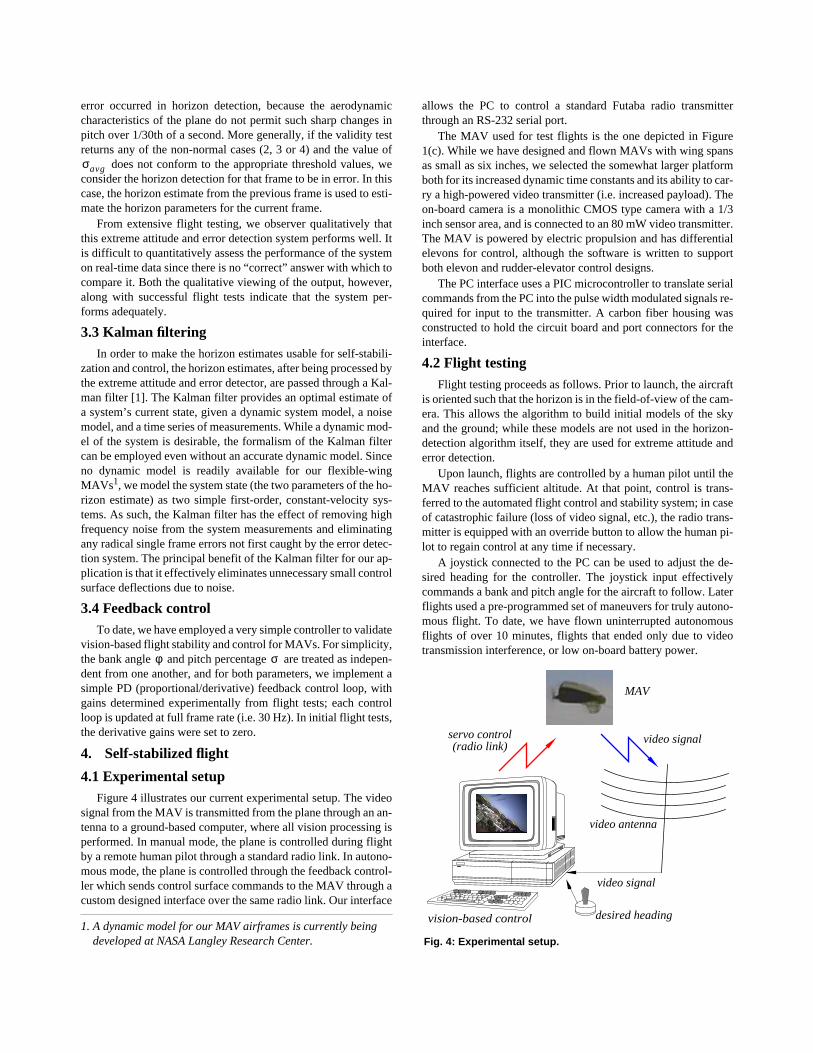
Figure 4 illustrates our current experimental setup. The videosignal from the MAV is transmitted from the plane through an an-tenna to a ground-based computer, where all vision processing isperformed. In manual mode, the plane is controlled during flightby a remote human pilot through a standard radio link. In autono-mous mode, the plane is controlled through the feedback control-ler which sends control surface commands to the MAV through acustom designed interface over the same radio link. Our interface
allows the PC to control a standard Futaba radio transmitterthrough an RS-232 serial port.
The MAV used for test flights is the one depicted in Figure1(c). While we have designed and flown MAVs with wing spansas small as six inches, we selected the somewhat larger platformboth for its increased dynamic time constants and its ability to car-ry a high-powered video transmitter (i.e. increased payload). Theon-board camera is a monolithic CMOS type camera with a 1/3inch sensor area, and is connected to an 80 mW video transmitter.The MAV is powered by electric propulsion and has differentialelevons for control, although the software is written to supportboth elevon and rudder-elevator control designs.
The PC interface uses a PIC microcontroller to translate serialcommands from the PC into the pulse width modulated signals re-quired for input to the transmitter. A carbon fiber housing wasconstructed to hold the circuit board and port connectors for theinterface.
4.2 Flight testing
Flight testing proceeds as follows. Prior to launch, the aircraftis oriented such that the horizon is in the field-of-view of the cam-era. This allows the algorithm to build initial models of the skyand the ground; while these models are not used in the horizon-detection algorithm itself, they are used for extreme attitude anderror detection.
Upon launch, flights are controlled by a human pilot until theMAV reaches sufficient altitude. At that point, control is trans-ferred to the automated flight control and stability system; in caseof catastrophic failure (loss of video signal, etc.), the radio trans-mitter is equipped with an override button to allow the human pi-lot to regain control at any time if necessary.
A joystick connected to the PC can be used to adjust the de-sired heading for the controller. The joystick input effectivelycommands a bank and pitch angle for the aircraft to follow. Laterflights used a pre-programmed set of maneuvers for truly autono-mous flight. To date, we have flown uninterrupted autonomousflights of over 10 minutes, flights that ended only due to videotransmission interference, or low on-board battery power.
1. A dynamic model for our MAV airframes is currently being developed at NASA Langley Research Center.
σ
avg
φ
σ
Fig. 4: Experimental setup.
video signal
video antenna
servo control video signal
vision-based control
MAV
(radio link)
desired heading

Figure 5(a) below plots a 72-second run of actual flight data,where the flight vehicle was under vision-guided control abovethe University of Florida campus (the full length of the flight ex-ceeded 10 minutes, and was primarily limited by low battery pow-er). During this flight, the MAV was instructed to execute atrajectory that consisted of straight line segments, followed byleft-bank turns (to keep the MAV within range of the receivingvideo antenna). For comparison, we also plot a 65-second seg-ment of manual (human-controlled) flight in Figure 5(b). Notehow much more erratic the human controlled flight is with respectto both the bank angle and pitch percentage. (Videos correspond-ing to these and other flight segments can be viewed at http://mil.ufl.edu/~nechyba/mav.) More recently, the same vision-based control system successfully flew over substantially differ-ent terrain at a Special Ops demo over Fort Campbell, Kentucky,where audience members, who had never previously controlledany type of aircraft (e.g. model airplane, MAV, etc.) successfullykept the MAV in the air for extended flights times.
Qualitatively, even our simple PD control system providesmuch more stable control than that of our best human pilots, bothin terms of steady, level flight, and in coordinated turns. As illus-trated by Figure 5(b), human pilots can typically not hold theplane on a steady, level heading for more than a few fractions ofa second; under vision-guided control, however, we were able tofly long straight segments that were limited only by the range ofthe video transmitter. Prior to the development of the horizon-tracking control system, only pilots with extensive training couldlearn to fly our micro air vehicles; with the automated control sys-tem, however, people who have never piloted any aircraft beforeare able to easily guide the MAV above the flying arena. It is thisfact alone that speaks the most to the potential value of this work.Ideally, one wants MAVs to be deployable by a wide range ofpeople, not only expert RC pilots; while much remains to be done,including automating landings and take-offs, the work in this pa-per is a big step towards the development and deployment of us-able and practical MAVs.
5. References
[1] B. D. O. Anderson and J. B. Moore,
Optimal Filtering
, Pren-tice-Hall, Englewood Cliffs, 1979.
[2] P. R. Ehrlich, D. S. Dobkin and D. Wheye, “Adaptions forFlight,” http://www.stanfordalumni.org/birdsite/text/essays/Adaptions.html, June, 2001.
[3] P. R. Ehrlich, D. S. Dobkin and D. Wheye, “Flying in VeeFormation,” http://www.stanfordalumni.org/birdsite/text/es-says/Flying_in_Vee.html, June, 2001.
[4] S. M. Ettinger,
Design And Implementation Of AutonomousVision-Guided Micro Air Vehicles
, M.S. Thesis, Electricaland Computer Engineering, University of Florida, August,2001.
[5] R. Fox, S. W. Lehmkule and D. H. Westendorf, “Falcon Vi-sual Acuity,”,
Science
, vol. 192, pp. 263-5, 1976.[6] P. G. Ifju, S. Ettinger, D. A. Jenkins and L. Martinez, “Com-
posite Materials for Micro Air Vehicles,”
Proc. of theSAMPE Annual Conf.
, Long Beach CA, May 6-10, 2001. [7] P. G. Ifju, S. Ettinger, D. A. Jenkins, and L. Martinez, “Com-
posite Materials for Micro Air Vehicles,” to appear in
SAMPE Journal
, July 2001.[8] D. A. Jenkins, P. Ifju, M. Abdulrahim and S. Olipra, “As-
sessment of Controllability of Micro Air Vehicles,”
Proc.Sixteenth Int. Conf. On Unmanned Air Vehicle Systems
,Bristol, United Kingdom, April 2001.
[9] Northern Prairie Wildlife Research Center, “Migration ofBirds: Orientation and Navigation,” http://www.np-wrc.usgs.gov/resource/othrdata/migration/ori.htm, June,2001.
[10] G. Ritchison, “Ornithology: Nervous System: Brain andSpecial Senses II,” http://www.biology.eku.edu/RITCH-ISO/birdbrain2.html, June 2001.
[11] W. Shyy, D. A. Jenkins and R. W. Smith, “Study of AdaptiveShape Airfoils at Low Reynolds Number in OscillatoryFlows,”
AIAA Journal
, vol. 35, pp.1545-48, 1997.[12] G. C. Whittow, ed.,
Sturkie’s Avian Physiology, Fifth Ed.
,Academic Press, San Diego, 2000.
Fig. 5: (a) Bank angle and pitch percentage for a self-stabilized flight (sequence of level-flight and left-turn segments), and (b) bank angle and pitch percentage for typical human-controlled flight.
0 10 20 30 40 50 600
0.2
0.4
0.6
0.8
1
0 10 20 30 40 50 60 700
0.2
0.4
0.6
0.8
1
0 10 20 30 40 50 60
-75
-50
-25
0
25
50
75
0 10 20 30 40 50 60 70
-75
-50
-25
0
25
50
75
bank angle (self-stabilized)
time (sec)
time (sec)
time (sec)
time (sec)
bank angle (human-controlled)
pitch percentage (self-stabilized) pitch percentage (human-controlled)
(a) (b)