Vision Based Robotics: Control, Navigation and … Based Robotics: Control, Navigation and Grasping...
34
Vision Based Robotics: Control, Navigation and Grasping Laxmidhar Behera Professor Department of Electrical Engineering Indian Institute of Technology Kanpur Uttar Pradesh, India – 208016
Transcript of Vision Based Robotics: Control, Navigation and … Based Robotics: Control, Navigation and Grasping...
Vision Based Robotics: Control, Navigation and Grasping
Laxmidhar Behera
Professor
Department of Electrical Engineering
Indian Institute of Technology Kanpur
Uttar Pradesh, India – 208016


Naturalization of Intelligence
• Alice lives in your house.
• Hears your family members
• Picks up vocabulary slowly and steadily.
• Starts speaking in a broken language.
• Becomes expert in your language.
• Learns to write poetry.
• Receives a Nobel prize in literature.

Necessity of Intelligent Controllers for
Nonlinear Systems
Model uncertainties and unmodeled dynamics necessitate alternative approaches for controlling the nonlinear systems
The most successful control systems on earth are biological ones
The effective way is to make the controller intelligent , ie., with minimum information about the system, the controller learns the system dynamics as well as the control actuation.

Contributions in Intelligent Control
Plant
Info. feedback
Adaptation & Learning
Control Law
• My group is one of the early proposers of control schemes for non-affine nonlinear systems with stability and convergence analysis using concepts such as network inversion and disturbance invariance. •Direct adaptive control of input affine systems – both continuous and discrete •Variable gain controllers for non-affine systems using TS fuzzy representation and Lyapunov stability theory
References: Behera et al. IEEE Tr NN 1996, IEE CTA 1995, 1996, 1999 , Patchaikani, Kar and Behera IEEE TR SMC-B 2006, Applied Soft computing 2009,

Variable Gain Controller using TS Fuzzy model – An example
The design model is chosen as TS fuzzy system represented with local dynamics as,
The global nonlinear dynamics is given by,
The design model is represented as a linear system with nonlinear disturbance
Patchaikani, Kar and Behera , IEEE SMC-B 2006
System Dynamics: Control Strategy:
If A is asymptotically stable and P is a positive definite matrix satisfying,
Suppose that,
Then the controller
asymptotically stabilizes the system
Controller gain for a Two link Manipulator

Control Theory in Neural Network
Parameter Optimization
Behera, Kumar and Patnaik, IEEE Tr. On NN 2006
NN parameter optimization problem is formulated as a control problem Weight update laws are derived using Lyapunov Function Approach Remarkable Contribution: Adaptive Learning Rate
Cost function:
Parameter update law:

Visual Control Set Up and the Problem
The Visual servo problem is to coordinate joint positions of the arm
through velocity actuation such that the actual visual feature
converges to desired visual features

Visual Manipulation in a Learning Enviroment
Behera and Nandagopal, IEEE control systems 1999, Patchaikani and Behera Elsevier-RA 2010, Kumar , Patchaikani, Dutta and Behera Robotica 2008, Kumar, Patel and Behera , Neural Processing Letters 2008, Kar and Behera , Intelligent Service Robotics 2010
•Model based visual servoing requires instantaneous updates of Image Jacobian (L) •L depends on visual features, Cartesian depth information of the object and end-effector and camera transformation matrix

SOM Based Control: Redundant Solutions
Swagat Kumar, Premkumar P., Ashish Dutta and Laxmidhar Behera, Visual Motor Control of a 7DOF Redundant Manipulator using Redundancy Preserving Learning Network, Robotica, Vol 28, No 6, 2010

Inverse-Forward Adaptive Scheme with SOM based Hint Generator
•A feed-forward network is used to learn the approximate forward kinematics •Inverse kinematic solution is obtained through a network inversion algorithm with SOM-SC based hint generator •Inverse-forward adaptive scheme does not require accurate forward kinematic model and hence reduces the number of training data •Forward kinematic model can be updated in real-time which increases accuracy and introduces adaptability to environment change.
Effective obstacle Avoidance is demonstrated with inverse-forward adaptive scheme
S Kumar, L Behera, TM McGinnity, Kinematic control of a redundant manipulator using an inverse-forward adaptive scheme with a KSOM based hint generator, Robotics and Autonomous Systems, vol. 58, 2010, page: 622-633

Inverse Jacobian Estimation using Self-Organizing Map
•Kinematic Jacobian from joint space to image space is a nonlinear function of joint angle, camera parameters and 3-D depth. •The accurate computation of the Jacobian over the entire workspace is difficult and in general estimation is performed around a small operating system. •Self-organizing map gives a holistic approach to learn the inverse Jacobian from the vision space to joint space over the entire workspace. •The accurate positioning of the end-effector is achieved with SOM as •Empirical studies on Cartesian space shows that the linear map of each neuron approximates the inverse Jacobian •It is easier to develop a globally Lyapunov stable controller with SOM in conjunction with a proportional controller •Weighted Jacobian can also be learned with SOM based on the desired additional task
P K Patchaikani, L. Behera, Visual Servoing of Redundant Manipulator with Jacobian matrix estimation using self-organizing map, Robotics and Autonomous Systems, vol. 58, 2010 page:978-990

Adaptive Critic based Redundancy Resolution
Weighted Minimum Norm and Kinematic Limit Avoidance are achieved and reported Obstacle Avoidance and Maximization of Manipulability are under progress
Patchaikani, Behera and Prasad, IEEE conf. SMC 2009, Patchaikani, Behera and Prasad, IEEE Tr. IE (2011)
A redundant Manipulator reaches the given end-effector position in multiple joint configurations. The control challenge is to identify the optimal joint configuration which accomplishes the desired additional cost Critic network is used to learn the costate dynamics
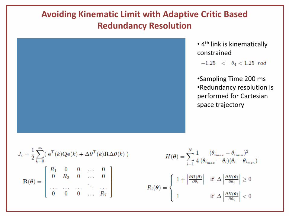
Avoiding Kinematic Limit with Adaptive Critic Based Redundancy Resolution
• 4th link is kinematically constrained •Sampling Time 200 ms •Redundancy resolution is performed for Cartesian space trajectory
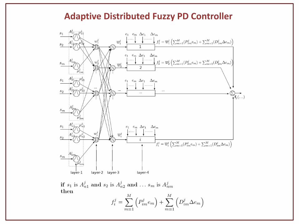
Adaptive Distributed Fuzzy PD Controller

Online adaptation algorithm
The online adaptation algorithm is derived based on the Lyapunov stability condition
• The Lypunov candidate function
• The derivative of the Lypunov candidate function
• The derivative of the Lyapunov candidate function will be negative definite

Challenges
• Computation of inverse kinematic Jacobian – The existing control algorithm needs to compute inverse Jacobian . The matrix pseudo-inverse
computation is intensive and suffers from numerical instability near singularity. Can the manipulator be kinematically controlled without numerical inversion of the Jacobian?
• Redundancy Resolution – Existing model based schemes perform redundancy resolution with obstacles known a priori
and is usually an off-line scheme, with end-effector motion and obstacle geometry defined in Cartesian space. Can real-time redundancy resolution be performed as per the demand of the dynamic situation, through visual feedback with trajectories and constraints are defined in image space?
• Computation of image Jacobian – Once features are selected, the image Jacobian, for a specific object is unique, but has to be
recomputed for another object. The existing methods focus on visual manipulation of known objects with known image Jacobians. Can the image Jacobian be computed for unknown objects given a set of Jacobians for a set of known objects? Can this image Jacobian computation be object-invariant?

Goal 4 Following the
manipulation of human demonstrator
Motion Analysis with VIicon and Path planning
Tennis playing Robot
1. Visual motor co-ordination of 29 DOF system 2. Dexterous Manipulation 3. Learning from Experience and Observation

Swarm aggregation using artificial potential field and fuzzy sliding mode
control with adaptive tuning technique
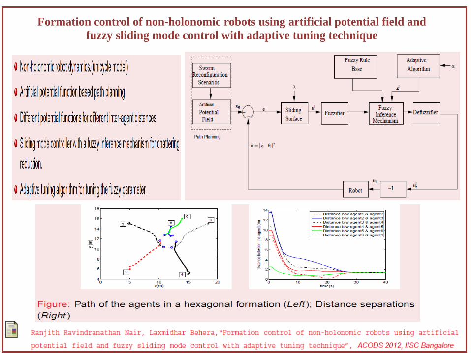
Formation control of non-holonomic robots using artificial potential field and
fuzzy sliding mode control with adaptive tuning technique

Robotic grasping of novel objects using Kinect
This work presents a novel solution to identify grasping point in a single RGB image and calculating the 3D coordinates using kinect depth stream.
Introduction:
Methodology: Use of Probabilistic Neural Network and supervised learning to train the PNN.
1 2 . . .
459 Synthetic images for training with labeled grasping points (for 1000 images per object)
459 features per patch are calculated
Use of binomial logistic regression to model probability Use of Maximum likelihood to obtain the parameters of PNN
1 2 . . .
459 460
Learned 460 parameters for the PNN
Image Processing to calculate the feature vectors for image.
Edge and Texture details are extracted using Nevatia-Babu and Laws’ Mask.
All these filters are also applied on scales of 1/3 and 1/9
For a patch, sum squared energy is calculated.
459 patches for a patch are thus obtained
The probability of a patch being a grasping point is calculated.
For a image (left) the heat map of probability is shown (right)
From patch of highest probability the grasping point is obtained.

Development of a Robotic Fish Autonomous robot with fish like motion to give high propulsion efficiency.
Head : hollow, housing Electronic Components and Battery. Sensors : 4 infrared sensors for obstacle detection. Tilt Sensor : for measuring the pitch and roll angle. Side fins : to adjust the pitch and also enables the fish to change its depth. Tail : 3 segment structure each having a servo motor to implement carangiform tail motion. Manufacturing Process : Rapid Prototyping.
Dynamic Equations:
Equation that the tail motion follows is: A = 2(c1x + c2x2) where x=tail length and A the amplitude of the sinusoidal motion at any length x. a=(F*cos(θ)-Dv)/m where a is the acceleration of the fish, F the thrust generated by tail motion , Dv is the drag force proportional to square of velocity of the fish and θ the angle between the robot fish heading and center line of its tail’s oscillation. Angular velocity is calculated as: Vr = 1.2f sin(θ) 1.2 is a coefficient from experiments.

Dynamic Equations:
• The motion of the fish is governed by the dynamic equations as described earlier.
• Actual Testing of the Fish Model was done at Intelligent System labs in a Mini-Swimming Pool.
Dv =(1/2)*Cf *S*U2 where Cf is the drag coefficient which depends on the Reynolds number & S is the wetted surface area and U is the forward velocity.
When thrust force Fthrust equals Dv max and the fish moves with 0 acceleration we get: Fthrust =1/2*Cf max*S*U2
max*ρ where ρ is water density.
Experiments

Visual tracking of non-rigid object Problem statement : Given a non-holonomic mobile robot having visual & sonar sensors, how to efficiently track a human in a cluttered environment
Work done Face detection algorithms are developed Leg detection algorithms based on the laser scan are developed
Problem encountered While tracking a human, human face is rarely visible to the robot Leg detection in 2-D map, generated using laser scan, does not provide any discriminating feature to distinguish between a human leg & other objects having leg shaped base e.g. A shaped ladder
Our approach Automatic detection of human • Background modeling and subtraction •Shadow removal • Outliers are removed using Aspect ratio filter horizontal projection histogram •Human is detected using template matching
•Segmentation of human body in 3 parts •Learn the hue histogram of human torso & legs
Human detection in dynamic environment •Back project the hue histogram of human torso & legs in current frame •Human silhouette is reconstructed by fusing depth information with back-projected image. • A shape analysis algorithm is developed to find the “two legs apart pattern” in the vertical projection histogram of the detected foreground.
Motion controller design • (x,y) centroid coordinates of human, yc is the contact point of human with ground in image frame, φ is the view angle of camera, Ψ is the angle of human with respect to robot, xm and ym is width and height of the image respectively
•Motion controller
xm
x
2
pk )(1 ycymkv p

I Capture RGB & depth
image Background modeling &subtraction
AR & HPH
Template matching
Segmentation & learn histogram
I
Initial automatic human detection
Human detection in subsequent frame
Backprojection (BP)
Human silhouette construction using depth & BP image
Template matching
Shape analysis
Human detected ?
UKF prediction
UKF update
yes No
Human tracking flowchart

Human detection in static environment (a) Background image (BI) (b) RGB image (c) Background subtracted (BS) image (d) new RGB image (e) BS image (f) image after shadow removal (g) ROI image (h) resized ROI image (i) edge image (j) distance transformed image (k) matched template (l) HPH of foreground blob (m) segmented human image (n) hue histogram of torso (o) hue histogram of legs

Human detection in dynamic environment (a) RGB image (b) depth image (c) backprojected image (d)
human silhouette (e) VPH of human silhouette (f) detected human image (g) magnified image of human
detection (h) RGB image (i) depth image (j) backprojected image (k) human silhouette (l) ROI image (m)
resized ROI image (n) edge image (o) distance transformed image (p) matched template (q) detected
human image (r) magnified image of human detection


Exo-skeleton Design with Vicon
• The brain signal control of the hand exoskeleton is under progress.
• A more versatile thumb exoskeleton can be designed using the Vicon data of the thumb.

Control of Exo-skeleton • As the human finger cannot be
modeled using single revolute joint, 4-bar mechanism is designed optimally to model each joint.
• The exoskeleton is actuated using the surface EMG signals extracted from the subject’s healthy forearm part through the muscle computer interface.
• The designed hand exoskeleton tracks the human finger motion successfully.

Thank You