VISION 2460 Installation GuideThe VISION 2460 Control Module is backed by a limited lifetime war -...
44
© 2018 KIRAMEK, INC., Aichi Japan Ver. 1.2, NOV. 2018 24V FACTORY KEYLESS SECURITY 2460 series
Transcript of VISION 2460 Installation GuideThe VISION 2460 Control Module is backed by a limited lifetime war -...

© 2018 KIRAMEK, INC., Aichi Japan Ver. 1.2, NOV. 2018
24V FACTORY KEYLESS SECURITY
2460series

Thank you for purchasing this VISION 2460 Vehicle Security System. The 2460 is a state of the art device that will pro-vide you with years of trouble free ser-vice if used properly. Please familiarize yourself with the content of this Owner’s Guide to get the most out of your new system. We trust you will enjoy using the product.

© 2018 KIRAMEK, INC.
NOTICE! Although reasonable efforts have been taken to ensure accuracy in this Owner’s Guide, Kiramek Inc. shall not be held liable for any errors, omissions, prop-erty damage, or injury resulting from the use of this information.
All product specifications and features are subject to change without notice.
TABLE OF CONTENTS
Limited Lifetime Warranty ................................... 1
Included Items ............................................ 2
Arming & Disarming ....................................... 3
Arming ................................................ 3
Confirmation Chirps .................................... 3
Disarming ............................................. 4
Manual Disarming ...................................... 5
Main Features ............................................ 6
Back Door Trigger ...................................... 6
Door Trigger ........................................... 6
2-Stage Shock Sensor ................................... 6
Ignition Trigger ......................................... 7
Error Chirp ............................................. 8
GWA (Ground When Armed) ............................. 8
SBS (Sector Bypass System) ............................... 8
Status LED & Trigger Memory ............................. 9
Light Flash ............................................. 9
Starter Kill ............................................ 10
Resume .............................................. 10
Valet Mode........................................... 10
Programmable Features ................................... 11
Reset to Factory Defaults ............................... 14
Troubleshooting .......................................... 15
Options ............................ QR CODE ON BACK COVER

1 © 2018 KIRAMEK, INC.
Limited Lifetime Warranty
The VISION 2460 Control Module is backed by a limited lifetime war-ranty against defective components and/or improper product assem-bly to the original purchaser for as long the vehicle is owned by that same purchaser, contingent upon installation by an Authorized VISION Dealer. All product warranties become void if the VISION 2460 system was not sold and installed by an Authorized VISION Dealer or the sys-tem is moved to another vehicle. All other parts and/or accessories that connect to VISION 2460 systems, including but not limited to the Starter Kill Relay, LED Program Switch, Shock Sensor, and Siren are warranted for one (1) year from the original date of purchase.
During the warranty period, Kiramek Inc. will repair or replace, at its sole discretion, any system component that is found defective in mate-rial or assembly during the warranty period, provided that the product is returned to Kiramek Inc. by an Authorized VISION Dealer and is ac-companied by a clear and legible copy of the original purchaser’s receipt. Any damage to your VISION 2460 system that results from normal wear-and-tear, accidents, improper use, neglect, faulty wiring, incorrect installation, modification, removal or defacement of the product serial number, alteration or repair outside Kiramek Inc or its Authorized VI-SION Dealers immediately voids this warranty.
This warranty is limited to defective parts only and does not provide any compensation whatsoever for damages associated with the VISION 2460 system or its accessories. This warranty does not cover installa-tion labor, product removal and/or reinstallation fees. This warranty is valid for the original purchaser only and may not be transferred to another party. Kiramek Inc makes no warranty against theft or vandal-ism of the vehicle in which the VISION 2460 system was installed. This warranty shall not be interpreted as an insurance policy against loss, nor shall Kiramek Inc be liable any in way for such loss, financial or otherwise.
WARNING! DO NOT ATTEMPT TO INSTALL THIS VISION 2460 PRODUCT YOUR-SELF BECAUSE SUCH WILL IMMEDIATELY VOID THE WARRANTY. THIS SECU-RITY SYSTEM MUST BE PROFESSIONALLY INSTALLED BY YOUR AUTHORIZED VISION DEALER TO VALIDATE YOUR WARRANTY.
KIRAMEK may opt to validate the above Warranty, in writing, for shipments outside Ja-pan, in cases where there is no local VISION Dealer available to perform the install.

2VISION 2460 OWNER’S GUIDE
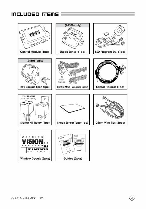
INCLUDED ITEMS
LED Program Switch PartsStatus LED
Program Switch
Control Module (1pc) Shock Sensor (1pc)
(2460B-only)
(2460B-only)
LED Program Sw. (1pc)
Sensor Harness (1pc)
Shock Sensor Tape (1pc)Starter Kill Relay (1pc)
Window Decals (2pcs)
VISIONIR SHOCK SENSOR
25cm Wire Ties (2pcs)
24V Backup Siren (1pc) Control Mod. Harnesses (3pcs)
MainHarness
Guides (2pcs)
24V FACTORY KEYLESS SECURITY
2460DIGI LINK∞ SMART
24V FACTORY KEYLESS SECURITY
2460series
DIGI LINK∞
SMART
8 9 6H- 1 CH- D 1
Co i l :12VDC
50A/30A85
86
87C1622
3087a
14VDC
p/n: 846-1AN(with coil diode)
VISION 2460 OWNER’S GUIDE3
Arming & disarming
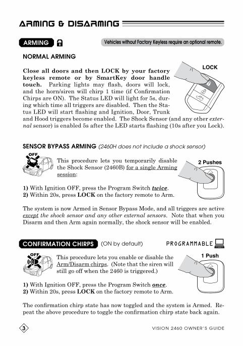
ARMING
CONFIRMATION CHIRPS
NORMAL ARMING
Close all doors and then LOCK by your factory
keyless remote or by SmartKey door handle
touch. Parking lights may flash, doors will lock, and the horn/siren will chirp 1 time (if Confirmation Chirps are ON). The Status LED will light for 5s, dur-ing which time all triggers are disabled. Then the Sta-tus LED will start flashing and Ignition, Door, Trunk and Hood triggers become enabled. The Shock Sensor (and any other exter-nal sensor) is enabled 5s after the LED starts flashing (10s after you Lock).
SENSOR BYPASS ARMING (2460H does not include a shock sensor)
This procedure lets you temporarily disable the Shock Sensor (2460B) for a single Arming session:
1) With Ignition OFF, press the Program Switch twice. 2) Within 20s, press LOCK on the factory remote to Arm.
The system is now Armed in Sensor Bypass Mode, and all triggers are active except the shock sensor and any other external sensors. Note that when you Disarm and then Arm again normally, the shock sensor will be enabled.
(ON by default)
This procedure lets you enable or disable the Arm/Disarm chirps. (Note that the siren will still go off when the 2460 is triggered.)
1) With Ignition OFF, press the Program Switch once. 2) Within 20s, press LOCK on the factory remote to Arm.
The confirmation chirp state has now toggled and the system is Armed. Re-peat the above procedure to toggle the confirmation chirp state back again.
PROGRAMMABLE
Vehicles without Factory Keyless require an optional remote.
OFF
OFF
LOCK
2 Pushes
1 Push
© 2018 KIRAMEK, INC. 4
arming & disarming
DISARMING
NORMAL DISARMING
UNLOCK by your factory keyless remote or by
SmartKey door handle touch. Vehicle parking lights may flash, doors will unlock, the horn/siren will chirp 3 times (if Confirmation Chirps are ON), and the Status LED will turn off. The 2460 is now Disarmed and you may enter the vehicle.
If the horn/siren chirps 4 times when you Disarm, it means something had triggered while you were away from the vehicle. In this case, the Status LED will flash to tell you what caused the trigger (see Trigger Memory, page 9).
If you Disable the Ignition Trigger (see pg.11) you can Arm/Disarm while the engine is running by using an optional remote; however, fac-tory keyless Lock/Unlock usually won’t work while the Ignition is ON.
DISARMING WITH IG ON
Programmable Feature No.2 prevents Relay Attacks by requiring 2 presses of Unlock on the factory remote to Disarm. See pages 11~12.
THWART RELAY ATTACKS
You cannot Disarm simply by pressing UNLOCK in cases where the 2460’s horn/siren was triggered by the opening of a door or the Ignition being switched ON. You must follow the above 4-step procedure!
IMPORTANT!
HOW TO DISARM AFTER A DOOR or IGNITION TRIGGER
If the horn/siren is triggered by the opening of a Door or by the Ignition being switched ON, you must perform the following proce-dure to Disarm:
1) UNLOCK with factory keyless (with doors/hood/trunk closed).2) Open the driver’s side door, enter the vehicle, then close the door. (The horn/siren will blast when you do this, if it is not already blasting.)3) Ensure the Ignition is OFF, then switch the Ignition ON then OFF.4) UNLOCK again with factory keyless. The system should now Disarm.
Sensor Trigger, Back Door Trigger or Nothing Triggered.UNLOCK

5 © 2018 KIRAMEK, INC.
arming & disarming
MANUAL DISARMING
You can manually Disarm using a secure code in the event your factory remote’s battery dies (see Note 2 below). The factory code is “6”, but you can change this code to another number of your choosing for greater security (see the bottom of this page).
1) Enter the vehicle. (The horn/siren will blast. Door can be open or closed.)
2) Turn ON the Ignition.
3) Within 30s, press the Program Switch the same number of times as
your Disarm Code. (Factory Default Code = 6)
4) Turn OFF the Ignition. (The 2460 should Disarm and the horn/siren should stop.)
1) If the 2460 won’t Disarm in Step-4 above, you entered the code incor-rectly. Start over from Step-2.
2) Many Push Start vehicles don’t allow the Ignition to be switched on in the absence of the Factory Remote. So if you lose or destroy your ve-hicle’s remote, you may not be able to Manually Disarm the 2460. But if your factory remote merely has a dead battery, you will be able to switch on the Ignition and Manually Disarm using the 4 steps above.
NOTES
MANUAL DISARM CODE MODIFICATION
The factory code is “6” but you should change it to another number between 1 & 30:
1) With the 2460 Disarmed, switch ON the Ignition.2) Press the Program Switch for 6s, until the horn/siren will chirp 3 times.3) Release the Program Switch after you hear the 3 chirps, then turn OFF the Ignition. The Status LED will light for 5s.4) Quickly switch ON the Ignition again (while the LED is lit for 5s).5) When the LED turns off, wait about 5s and you will see the LED start to flash. Take note of the flashes as the number of flashes will be the num-ber of your Disarm Code. Turn OFF the Ignition to program your code.The LED will then flash the same number of times as your Disarm Code.
If you added any optional VISION transmitters, you must relearn them.
PROGRAMMABLE

6VISION 2460 OWNER’S GUIDE
MAIN FEATURES
The horn/siren will blast for 30s when either front door is opened while Armed. Parking lights may also flash. A special Disarming procedure is required when a door is opened while Armed. See bottom half of page 4 on how to Disarm in this case. Also see Table-1 on page 9 for Trigger Memory details.
2-STAGE SHOCK SENSOR
1st Stage (“Warning Chirps”). Each time the Shock Sen-sor detects a light impact to the vehicle body, the siren will chirp 5 times. However, the Shock Sensor will not trigger the siren while in Sensor Bypass Mode.
2nd Stage (“Full Trigger”). When the Shock Sensor de-tects a hard impact to the vehicle body, the horn/siren will blast for 30s (or until Disarmed with the factory remote). However, the Shock Sensor will not trigger the siren while in Sensor Bypass Mode. Also see Table-1 on page 9 for Trig-ger Memory details.
See pages 15-16 for common shock sensor problems and solutions.
The horn/siren will blast for 30s when the Back Door of your truck is opened while Armed. Parking lights may also flash. You can easily Disarm while the siren is blasting by pressing UNLOCK on your factory keyless remote. If you Arm with the Back Door left open, it will be bypassed along with the Shock Sensor (2460B) until closed. See Table-1 on page 9 for Trigger Memory details.
BACK DOOR TRIGGER
DOOR TRIGGER
5 Chirps
30s Blast
2460B

7 © 2018 KIRAMEK, INC.
main features
IGNITION TRIGGER
Ignition Trigger Enabled (default) The horn/siren will blast for 30 seconds when the Ignition (IG) is switched ON while the sys-tem is Armed, and you cannot Arm when the Ignition is ON. See bottom half of page 4 on how to Disarm in this case. Also see Table-1 on page 9 for Trigger Memory details.
Ignition Trigger Disabled (user-programmable) When the Ignition (IG) Trigger is Disabled, you can Arm with IG ON. Also, if IG switches ON while al-ready Armed, the siren will not trigger and instead Shock Sensor (2460B) and IG triggers are disabled but Door and Back Door triggers remain enabled. This allows remote starter use and allows you to run the engine while Armed without triggering the siren. Opening the Door or Back Door will trigger the siren. The Shock Sensor is re-enabled when IG goes OFF while Armed. If a front Door was opened while Armed and IG ON, the siren will trigger, and if IG goes OFF while still Armed, attempts to turn IG ON will trigger the siren. This intelligent switching is called IIP.
IIP (Intelligent Ignition Protection) IIP temporarily enables the Ignition Trigger after a horn/siren trigger caused by a Door-open condition (not the Back Door).
Purpose. Most “remote start compatible” car alarms bypass all trigger inputs after the Ignition is switched ON. So if a thief opens a door the siren will trigger; but the thief can then close the door, turn on the Igni-tion, wait until the siren stops, then drive away in silence because the Ignition-ON state prevents the siren from triggering again! Yet other car alarms that always trigger the siren when the Ignition turns ON of-fer no remote start compatibility at all and not allowing you to sleep in the vehicle protected with the engine running. IIP solves this problem.
How it works. If you Disable the Ignition (IG) Trigger, then switch ON IG (or start the engine) and Arm, all sensors and the IG trigger are dis-abled but Door and Back Door triggers are active. If the 2460 is Armed and the horn/siren is triggered by a Door when IG is OFF, IIP automati-cally Enables the IG Trigger, and the 2460 will trigger the horn/siren again if IG later goes ON. (Disarming and Arming again will restore your programmed IG Trigger setting.)
PROGRAMMABLE
IG ONIG ONLOCK
ACCON
START
30s Blast
STARTSTOP

8VISION 2460 OWNER’S GUIDE
main features
A “sector” is the Ignition, a Door, the Back Door, or attached Sen-sors. When a sector triggers the horn/siren a certain number of times (see below), that sector is bypassed (disabled) until you Dis-arm and Arm again. This limits noise pollution caused by multiple horn/siren triggers in a short period of time, such as when you park near construction sites or if animals jump on the vehicle repeatedly.
DOOR — If either front door is left OPEN, the horn/siren blasts up to 5 times (30s each time), then the Doors are bypassed until closed. The BACK DOOR WHT/BLK input is bypassed after triggering 10 times.
IGNITION — If the Ignition is left ON, the horn/siren blasts up to 10 times (30s each time) and then the Ignition is bypassed until you Disarm & Arm again.
SENSOR (2460B) — Warning triggers (5 chirps) and Full Triggers (30s siren) are independently bypassed after triggering 10 times. You must Disarm and then Arm again to re-activate.
SBS (Sector Bypass System)
ERROR CHIRP
If a Door or the Back Door is open when you Arm, you will hear 1 chirp (if Confirmation Chirps are enabled) followed by 2 chirps (even if Confirma-tion Chirps are disabled). The 2 chirps are Error Chirps that notify you the door left open won’t trigger the horn/siren, and neither will opening other doors. But 5 seconds after you close all open doors, the horn/siren will trigger if you later try to reopen a door. NOTE: Some vehicles don’t allow factory keyless Lock & Unlock operation when doors are left open.
GWA (Ground When Armed)
The 2460 puts a constant (–)Ground on the Yellow output wire while the system is Armed. Optional accessories like LED scanners (visual theft deterrents) can be activated by this con-trol line while Armed. When the system is Disarmed, the GWA output becomes an open circuit (NPN transistor switch off and no longer supply-ing Ground), causing all attached devices to turn off. See the Installation Guide for electrical specifications.
OPTIONAL

VISION 2460 OWNER’S GUIDE9
main features
The Status LED flashes slowly about once per second while the system is Armed, acting as a visual theft deterrent. The LED turns off when the system is Disarmed, unless there was a horn/siren trigger.
TRIGGER MEMORY
The LED flashes rapidly while the full horn/siren blast is going off and keeps flashing rapidly even after the horn/siren stops. When you Disarm, the Status LED will change its flashing pattern ac-
cording to Table-1 below, showing you by repeating flashing patterns what triggered the horn/siren.
If the horn/siren triggered more than once, the LED will show you the cause of up to the last 3 triggers. For example, if the Back Door was opened and then a cab Door and then the Ignition was switched ON, the 30s siren blast would be triggered and on your return to the vehicle, when you Un-lock, the LED would flash 2 times to indicate a Door was opened, the flash 3 times to indicate the Back Door opened, and the flash 6 times to indicate the Ignition had been switched ON. Those flashing patterns would then re-peat on the LED until you either switch ON the Ignition or until you Arm.
STATUS LED
TABLE-1 Status LED Trigger Memory
LED Flashes What Triggered the Horn/Siren
2 Door (WHT wire)
3 Back Door (WHT/BLK wire)
6 Ignition (GRN/WHT wire)
7 Sensor (Full Trigger only)
There are no LED Flashes to show if the power was cut and then restored.
LIGHT FLASH
If the GRN output wire is connected, Parking lights will flash continuously for the entire 30s duration of full horn/siren triggers, and will flash 5 times when shock sensor Warning Chirps are triggered. NOTE! Some vehicles do not support Parking light flash unless an optional relay is installed.
OPTIONAL

© 2018 KIRAMEK, INC. 10
Valet mode disables all security system functions, ensuring the horn/siren will never trigger. Valet Mode is useful when you must hand over your keys to a valet or maintenance technician, eliminating worry they would trigger the horn/siren by accident.
Activation: With the Ignition switched OFF and the 2460 Disarmed, press and hold the Program Switch for more than 6s, until the Status LED turns OFF. (When the LED turns OFF, release the Program Switch.)
Deactivation: Press and hold the Program Switch again for 6s, until the LED turns OFF. Security features are now restored. (You may or may not hear 2 quick chirps the first time you Arm, to inform you that you have just exited Valet Mode.)
main features
When you activate Valet Mode, the Status LED will not blink and you will not receive any indication of being in Valet Mode. The security sys-tem will be completely turned off. This also means that someone could break into your truck. Our company accepts no liability whatsoever if your truck is stolen or vandalized or its contents stolen due to your hav-ing entered Valet Mode. You use this feature at your own security risk.
CAUTION!
Valet Mode PROGRAMMABLE
STARTER KILL
If the YEL/BLK output wire is properly connected to the included Starter Kill Relay (see Install Guide pg.7), the engine won’t start until the 2460 is Disarmed. The relay is “normally open,” which means the Starter wire is broken until the 2460 is Disarmed and the Ignition is switched ON.
RESUME
RESUME is State Memory that remembers if the system was Armed or Disarmed when the main power is cut. When power is restored, the 2460 will power-up Disarmed if it was Disarmed when the power was cut. If originally Armed, it will power-up Armed and with the horn/siren blaring.
Push 6s

11 © 2018 KIRAMEK, INC.11
PROGRAMMABLE FEATURES
You can change some features of the 2460 by using the Program Switch. Perform the following 5-step procedure to change the fea-tures shown below in Table-2:
1. Start the engine and then Stop the engine. (Required for Hybrid engines.)
2. With the Ignition OFF, Arm the 2460 and then immediately Disarm.
3. Within 20s, turn ON the Ignition.
4. Press the Program Switch the same number of times as the feature you want to program — refer to the “No.” column in Table-2 below. (For ex-ample, to change “Ignition Trigger,” push the Program Switch 3 times.)
5. Turn OFF the Ignition.
TABLE-2 Feature Selection Menu
No. Feature Description Toggle Settings
2 Require 2 Unlocks to Disarm OFF ON
3 Ignition Trigger Enable Disable
4 Parking Lights ON when IG ON OFF ON
5 Error Chirp ON OFF
6 Ignore Factory Unlock (Disarm) Signal NO YES
7 Parking Light Control Solid-ON Flashing
8 Auto Arm OFF ON
9 Horn or Siren Output Pulsed Continuous
10 Auto Rearm OFF ON
17 Exterior Illumination OFF ON
FACTORY DEFAULT SETTINGS SHOWN IN BOLD TEXT ABOVE
1) After you complete Step-5 above, the Status LED will flash the same number of times as the feature you just programmed. Because the set-tings merely “toggle,” there’s no indication of the setting you toggled to. Test your 2460 system to confirm your programmed settings. To program another setting, repeat the 5 steps above.
2) To Reset to Factory Defaults, see page 14.
NOTES

12VISION 2460 OWNER’S GUIDE
programmable features
If you Disable the Ignition Trigger and then set this feature to ON, while the system is Armed, parking lights will illuminate while IG is ON, and parking lights will turn off when either IG goes OFF or when you Disarm.
4 Parking Lights ON when IG ON
When set to Enable (default), the system will trigger the horn/siren when the Ignition (IG) turns ON while Armed, as described on page 7. NOTE: When Enabled, you can’t Arm while IG is on, not even with an optional remote.
When set to Disable, the system will bypass the Shock Sensor (2460B) and Ignition triggers when the Ignition turns ON while Armed. This is useful if you have a remote engine starter. Also, to sleep in the vehicle with the engine running, first start the engine and then Arm using an optional remote (keyless Lock/Arm doesn’t work when IG is on in most vehicles).
3 Ignition Trigger
2 Require 2 Unlocks to DisarmOFF by default. Set to ON to prevent Keyless Relay Attacks*. When ON, pressing Unlock only 1 time will NOT Disarm. To Disarm you must press Unlock 2 times on your factory remote within 3 seconds. This prevents Relay Attacks because even if a Relay Attack thief touches the outside door handle many times, only one Unlock signal is sent. Unlike the door handle, your factory remote sends a signal each time you press Unlock on the re-mote. So pressing 2 times on your outside door handle to Unlock will NOT Disarm the 2460. You must press Unlock twice on your factory remote.
If you program Feature No.2 to be ON, you then cannot program Feature No.6 to be ON. Conversely, if you have Feature No.6 programmed to be ON, you cannot program Feature No.2 to be ON until you turn OFF Fea-ture No.6. *Relay Attack Info: https://bit.ly/2OFjpnp
If your car has wireless keyless entry (pressing Lock/Unlock on your factory key locks/unlocks doors) but does NOT allow you to Lock/Unlock by merely touching the outside door handle, Relay Attacks are impossible on your car and therefore you can leave Feature No.2 (& No.6) set to OFF.
NOTE

VISION 2460 OWNER’S GUIDE1313
programmable features
9 Horn or Siren OutputWhen set to Continuous, the system will send a continuous (–)GND out-put to activate a 24V Siren during 30s Triggers.
When set to Pulsed (default), the system will feed a pulsed (–)GND (1A max.) output. This is needed when connecting to the vehicle’s horn, but it can also be useful when using a KB24-1 siren with its blue loop wire cut.
This feature automatically Arms the system when you do the following: (1) turn Ignition ON & OFF then (2) Open & Close any cab Door (not the Back Door). Upon seeing these events, the system will Arm 20s after the last cab Door is closed. The doors will NOT be locked so you won’t be locked out if you leave your keys in the car, but the system will be Armed and will trigger if any door is opened.
8 Auto Arm
7 Parking Light ControlWhen set to Flashing, parking lights flash when Feature No.4 and/or Fea-ture No.17 are set to ON. When set to Solid-ON, parking lights illuminate continuously when Feature No.4 and/or Feature No.17 are set to ON.
6 Ignore Factory Unlock (Disarm) SignalSet to YES to stop Keyless Relay Attacks by not Disarming when you press Unlock. (Ignores the BLU/YEL Door Unlock input.) After you Unlock and open a door, you have 20s to Disarm either Manually (pg.5) or with an optional remote, otherwise the horn/siren will blast. NOTE: Feature No.2 is more convenient (see pg.12) if your vehicle can produce 2 unlock pulses.
ON by default. See Error Chirp description on page 8. When set to OFF, any doors still open when you Arm will be bypassed but you will not hear the Error Chirp sound to confirm door bypassing. This is useful for vehicles with automatic sliding doors that take a long time to close.
5 Error Chirp

© 2018 KIRAMEK, INC. 14
This feature automatically Rearms the system 60s after it is Disarmed, unless a Door is opened or the Ignition goes ON during the 60s. Doors will be locked when the system Rearms.
10 Auto Rearm
If set to ON, when you Disarm, parking lights will illuminate for 30s or until any door is opened or until the Ignition is switched ON, in order to illuminate the area around the vehicle for greater visibility and security.
NOTE: Exterior Illumination behavior can be adjusted by using Feature No. 7, Parking Light Control.
17 Exterior Illumination
RESET Programmable Features to Factory Defaults.NOTE#1: You must reprogram all your optional transmitters after Reset.NOTE#2: You must know where the 2460 control module is located to Reset.
1. Disarm and ensure Ignition is OFF.
2. Disconnect the 2460’s main harness. (White connector with 6 thick wires.)
3. Push-and-hold the Program Switch.
4. Reconnect the 2460’s main harness. The siren will blast.
5. Release the Program Switch. The siren will stop, LED turns On.
6. Switch ON the Ignition. Horn/Siren will chirp 3 times, LED turns Off.
7. Switch OFF the Ignition. LED will light 5s, then flash 6 times (Manual Disarm Code resets to 6). RESET complete.
Consult the manual that came with your transmitter (2-way pager or 1-way 3-button remote) to learn how to reprogram them. Also remember that a full RESET will revert your Manual Disarm Code to “6” (factory default).
NOTE
programmable features

15 © 2018 KIRAMEK, INC.
TROUBLESHOOTING
FACTORY KEYLESS REMOTE WAS LOST, HOW TO DISARMIf the factory remote was lost, you may not be able to Disarm if you have a Push Start Ignition that requires the presence of the factory remote. In such a case, you must to contact your dealer for a replacement factory remote. But if you have an older turn-to-crank style Ignition, you can Disarm the 2460 by Manual Disarming, as described on page 5.
SOMETIMES CAN’T ARM/DISARM WITH THE FACTORY REMOTE• On some cars, if you rapidly press Lock and Unlock on the factory re-
mote, the 2460 may stop responding to the remote. In this case the fix is simple — just wait longer between Lock and Unlock presses.
• If Confirmation Chirps (pg.3) are enabled, did you hear a single horn/siren chip when you tried to Arm? If not, the Ignition may be ON. You cannot Arm the system while the Ignition is ON unless you have an optional TR537S or TR365 remote (see “Ignition Trigger” on page 12).
THE SYSTEM IS DEFINITELY ARMED, BUT IT WON’T TRIGGER THE SIREN!• It may be in Valet Mode. See page 10. • It may be in Sensor Bypass Mode. See page 3.
HORN/SIREN BLASTS WHEN THE BACK DOOR IS OPENED• If you need to open the Back Door, first Disarm the 2460. • If the Back Door is triggering the horn/siren while Armed, even though
the Back Door is NOT opened, there could be an intermittent connec-tion to the Back Door on the WHT/BLK wire. Check that connection.
CANNOT DISARM WHILE THE HORN/SIREN IS BLASTING• You must follow the 4-step procedure “HOW TO DISARM AFTER A
DOOR or IGNITION TRIGGER” on page 4.• Your factory remote’s battery may be dead. Use Manual Disarming (p5).
SHOCK SENSOR 1st STAGE “WARNING” TRIGGER DOESN’T WORKExamine the shock sensor and look closely at the two LEDs. When you lightly tap on the sensor, do you ever see a Green LED light?
• If you never see Green light, adjust the sensitivity knob on the sensor.• If after increasing sensitivity you still don’t see the Green LED, it
could be that the suspended element inside the sensor body was shifted out of place. See page 15 in the Install Guide on how to resolve this.
• If you do see a Green light, the sensor is functioning properly. That means there is like a wiring problem. Check that the sensor wire har-ness is properly connected at both ends.

16VISION 2460 OWNER’S GUIDE
30s HORN/SIREN BLAST OCCURS WITH LIGHT IMPACT TO THE VEHICLE• You mounted the shock sensor (2460B) to metal. Remount on a firm
plastic part of the vehicle.• Turn down the shock sensor sensitivity to 50% or less.• Check your Shock Sensor wire harness, end-to-end from the sensor
itself to the 2460 control module, and ensure no other wires are touch-ing or in close proximity to it (some wiring can cause interference that can false trigger the shock sensor). Also make sure no RF transmitting devices are in close proximity to the shock sensor or its wire harness.
• If you added an optional Ultrasonic sensor, it is very likely that the controller of the ultrasonic sensor (not the emitters) was placed too close to the shock sensor. The Ultrasonic sensor’s controller should be placed more than 30cm (1 foot) away from the shock sensor to avoid interference.
CAN’T ARM WITH IGNITION ONEven if you programmed the Ignition Trigger to be Disabled (see page 11), you cannot Arm using the factory remote Lock button while the Ignition is ON. However, if you purchase the optional TR537S 2-way paging system or the TR365-series 1-way remote, you will then be able to Arm with the Ignition ON if the Ignition Trigger is set to be Disabled. (NOTE! Even with the optional remote, you cannot Arm with IG ON if the Ignition Trigger is Enabled.)
CAN’T START ENGINE• Is the included Starter Kill Relay installed? If installed and if you
also have Ignition Trigger DISABLED, the Ignition can be switched ON even while Armed and the Siren won’t trigger; but when you try to start the engine while the 2460 is Armed, the Starter Kill relay will prevent starting. First Disarm the 2460, then start the engine.
• It could be low voltage. Has it been a long time (about a month) since you started the engine? If you have an optional remote attached and have not started your engine in several weeks, it could be that your vehicle battery voltage is too low. Check your vehicle battery voltage and charge if necessary. You may not be able to start your engine if the battery voltage is lower than 22V. Even if your battery voltage is 24V you still could have a bad 24V battery or bad 12V battery pair. The 2460 and attached sensors and remotes will continue operating if the vehicle battery voltage falls as low as 8.5V, but any 24V relays you may be using usually won’t work below 12.5V. If battery voltage falls below 8.5V, 2460 sensors will stop working, and below 5.5V the 2460 CPU will stop and all security functions will shutdown.
TROUBLESHOOTING

9-183-1 I tayama-cho, Handa-shi , Aichi-Ken 475-0936 JAPANTEL: +81-569-20-5585 • FAX: +81-569-20-5586 • EMAIL: [email protected]
VISION products are engineered in Japan and manufactured in strict accordance with Japanese QC standards at an ISO9000/QS9000 certified factory.
Add-on sensors, remotes and installation parts can be found on our website:www.visionsecurity.jp/en/

© 2018 KIRAMEK, INC., Aichi Japan Ver.1.2, NOV. 2018
24V FACTORY KEYLESS SECURITY
2460series

INSTALLERS, READ THIS MANUAL THOROUGHLY! The 2460 must be connected by an experienced VISION installer. All product warranties im-mediately become void if the 2460 is not in-stalled by an authorized dealer.
If you acquired this product without profes-sional installation, DO NOT install it yourself to save a little money at the risk of damaging your vehicle or causing physical injury.

© 2018 KIRAMEK, INC.
TABLE OF CONTENTS
Precautions & Safety ....................................... 1
Installation Tips ........................................... 2
Technical Specifications ................................... 3
Included Items ............................................ 4
Read This First ............................................ 5
System Wiring Diagram ..................................... 6
3-Wire Harness ............................................ 7
4-Wire Harness ............................................ 8
6-Wire Main Harness ...................................... 11
GWA Output .......................................... 12
Siren ................................................. 13
Mounting System Components ............................. 15
Adjusting the Shock Sensor ................................ 17
Troubleshooting .......................................... 18
Options ................................................. 20
NOTE: Consult Owner’s Guide page 11 for Feature Programming.
NOTICE! Although reasonable efforts have been taken to ensure accuracy in this In-stall Guide, Kiramek Inc. shall not be held liable for any errors, omissions, property damage, or injury resulting from the use of this information.
All product specifications and features are subject to change without notice.

1 © 2018 KIRAMEK, INC.
Precautions & Safety
OPERATION. Use of the 2460 outside its intended purpose, as described in this Install Guide and the 2460 Owner’s Guide, could result in damage to the vehicle or surrounding property, or cause serious injury or even death. As the installer of this security system, it is your responsibility to ensure that the vehicle owner is properly informed of all the details of your instal-lation which are pertinent to safety.
SAFETY POINTS TO ABIDE BY :
1. Never start the vehicle’s engine in enclosed spaces that lack adequate ventilation. Extended exposure to carbon monoxide exhaust fumes can result in death!
2. Do not disconnect the vehicle’s battery, as it could cause serious prob-lems with airbag systems, anti-theft radios or vehicle diagnostics. If you absolutely must disconnect the vehicle’s battery, first disconnect the main power wiring harness of the 2460 and then disconnect the vehicle’s battery.
3. Do not proceed with installing this system in vehicles that do not have a 24-volt electrical system. This system may not func-tion properly and/or draw excessive current when used in 12-volt vehicles.
4. Do not install the 2460 control module or associated sensors in or near water, or in a location where water could gather. The 2460 is not waterproof and an electrical short could occur if water gets in- side. Only the siren can safely be installed in the engine compart-ment.
5. Do not install the 2460 control module in an environment of intense condensing humidity or steam, in an area with an unusually large number of airborne particles, or any place where oil could build up inside the control module case. All of these extreme environments could lead to an electrical short and possible cause a fire.
6. Avoid installing the 2460 and its associated sensors near sources of intense RF transmissions which could possibly interfere with the op-eration of the system. If you find the system is randomly working and not working, consider relocating any attached sensors.

2VISION 2460 INSTALL GUIDE
Installation Tips
Steps Toward a Professional Installation:
• Ensure all electrical contacts cannot easily break by tugging on the wires. We highly recommend the use of optional PosiTap brand connec-tors for most connections such as to the Door Lock Motor wires, Hazard light wires, and Trunk Release wire. And we recommend a PosiLock connector when connecting to the Siren. Alternatively, you can use sol-der, but test your connections and then securely cover with electrical tape, heat shrink tubing and/or corrugated tubing.
• Use only a DMM (digital multi-meter) to test leads or take voltage read-ings. Do not use “test lights” or “logic probes” (“computer-safe test lights” included) because they draw a large amount of electrical current that could overload and destroy sensitive circuitry in the vehicle.
• Manually turn off all lights (such as the dome light) that illuminate when a hatch is opened so you will not run down the battery. If you can-not manually turn off all the lights, then remove the appropriate fuses and don’t forget to replace the fuses after your installation is complete.
• Roll down a window to avoid locking the keys in the car.
• If unsure, consult the vehicle owner about where the Status LED, Con-trol Module, Siren, Antenna Unit, and Sensors should be mounted.
• If you need a constant +24 volt power source under the dash, splice off the wire leading to pin-16 (POWER) at back of the vehicle’s OBD plug. OBD pin-16 supplies a constant +24V. Alternatively, run a thick wire directly to the vehicle’s battery or consult vehicle schematics.
• When running extension wire, always use a wire gauge that is as big or bigger than the wire you are extending.
Useful Installation Items:
• DMM (digital multi-meter)
• Battery-powered drill & driver
• Electrical Tape or Heat Shrink Tubing
• Brake Cleaner or Alcohol degreaser
• Soldering Iron & Solder
• Corrugate Tubing
• Wire Stripper/Crimper
• Wire ties

3 VISION 2460 INSTALL GUIDE
Technical Specifications
Operating Voltage:Current Consumption:
Operating Temp.:Certification:
Control Module
Siren
24Vdc7.1mA (Average, Armed w/ LED flashing)
5.8mA (Average, Disarmed)
(Does not include Sensor or Siren consumption. See below.)
-40°C to +85°CIP40
Operating Voltage:Current Consumption:Operating Temp.:Loudness:Audio Generator: Housing:Certification:Replacement P/N:
24Vdc5.5mA (trickle charge), 1A (during full siren blast)
-40°C to +125°C125dB (measured 30cm/1ft from speaker)
1-tone (6-tone selectable by cutting loop on siren)
Water-resistant (cannot be submerged)
IP54KB24-1
Shock Sensor
Operating Voltage:Current Consumption:
Operating Temp.:Sensor Technology:Certification:Replacement P/N:
12Vdc (supplied by 2460 Control Module)
Adds 2.5mA(avg.) to Control Module Current Con-sumption when Armed, 0mA when Disarmed-40°C to +85°CInfra-red Beam DeflectionIP40 (durability tested to IP50)
318-052
2460B
2460B
4© 2018 KIRAMEK, INC.
INCLUDED ITEMS
Control Module (1pc) LED Program Sw. (1pc)
Sensor Harness (1pc)
Shock Sensor Tape (1pc)Starter Kill Relay (1pc)
Window Decals (2pcs)
25cm Wire Ties (2pcs)
Control Mod. Harnesses (3pcs)
MainHarness
Guides (2pcs)
24V FACTORY KEYLESS SECURITY
2460DIGI LINK∞ SMART
24V FACTORY KEYLESS SECURITY
2460series
DIGI LINK∞
SMART
8 9 6H- 1 CH- D 1
Co i l :12VDC
50A/30A85
86
87C1622
3087a
14VDC
p/n: 846-1AN(with coil diode)
(2460B-only)
24V Backup Siren (1pc)
Shock Sensor (1pc)
(2460B-only)
VISIONIR SHOCK SENSOR

NO SETUP REQUIRED Most factory keyless upgrade alarm systems require you to learn the vehicle’s door lock motor and/or hazard light signals before the alarm can be used. But with VISION 2460, no special setup is required. If the Hazard lights flash when the factory keyless LOCK or UNLOCK is used, the 2460 is compatible and can be installed as described on the following pages. If Hazards don’t flash during keyless operation, you could connect the WHT/RED Hazard input to constant (+)24V, but use of an optional remote is best.
IMPORTANT CAR BATTERY INFORMATION Since the VISION 2460 draws power from the vehicle’s electrical system, it is important that we say a few words about battery life and battery drain. Most batteries in modern vehicles (2010 and later) have a service life of 2-3 years under normal usage conditions where no aftermarket accessories are added to the vehicle at all. That remains true even if the vehicle battery is hardly ever used. Adding electronic accessories to the vehicle may con-tribute to a slightly shorter life, depending on the car and battery. This is especially true if the vehicle is equipped with a high amperage audio system. Some modern vehicles do not run the alternator all the time in order to improve fuel economy. What this means is, there are times when you drive your vehicle and the battery may not be charged until the voltage falls below a certain level. Furthermore, the shorter the distance you drive, the less charge your battery will receive. All said, the age of your battery combined with the amount of charge the battery normally receives will determine the voltage level. If the voltage falls too low, the VISION 2460 (as well as other vehicle electronics) could be adversely affected, resulting in unexpected operation. So even though the VISION 2460 draws very little power from the battery, other factors could contribute to a low voltage condition. As such, you should have your vehicle battery checked annually. If something goes wrong with the 2460, check your battery voltage! Note that the following situations have a negative impact on the battery:
1. Traffic jams, Night driving, Driving in Rain or Snow.2. Frequent use of Air Conditioning.3. High amperage accessories like car audio, TV and navigation systems.4. Driving short distances.5. Using car electronics frequently with the engine off.6. Driving infrequently, such as once a week or less.
READ THIS FIRST
6VISION 2460 INSTALL GUIDE
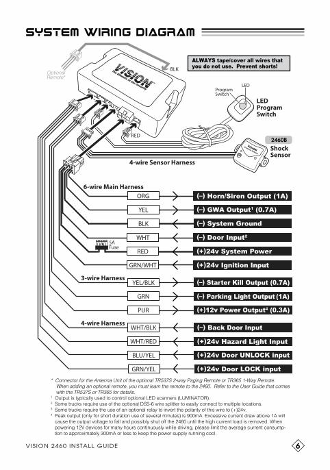
SYSTEM WIRING DIAGRAM
2460B
3-wire Harness
4-wire Harness
4-wire Sensor Harness
RED
BLKOptionalRemote*
* Connector for the Antenna Unit of the optional TR537S 2-way Paging Remote or TR365 1-Way Remote. When adding an optional remote, you must learn the remote to the 2460. Refer to the User Guide that comes with the TR537S or TR365 for details.1 Output is typically used to control optional LED scanners (LUMINATOR).2 Some trucks require use of the optional DSS-6 wire splitter to easily connect to multiple locations.3 Some trucks require the use of an optional relay to invert the polarity of this wire to (+)24v.4 Peak output (only for short duration use of several minutes) is 900mA. Excessive current draw above 1A will cause the output voltage to fall and possibly shut off the 2460 until the high current load is removed. When powering 12V devices for many hours continuously while driving, please limit the average current consump- tion to approximately 300mA or less to keep the power supply running cool.
5AFuse
ORG
YEL (–) GWA Output1 (0.7A)
BLK (–) System Ground
WHT (–) Door Input2
RED
GRN/WHT
(+)24v System Power
(+)24v Ignition Input
(–) Horn/Siren Output (1A)
LEDProgramSwitch
ProgramSwitch
LED
6-wire Main Harness
ShockSensor
VISIONIR SHOCK SENSOR
GRN
YEL/BLK (–) Starter Kill Output (0.7A)
(–) Parking Light Output (1A)
PUR (+)12v Power Output4 (0.3A)
WHT/RED
BLU/YEL (+)24v Door UNLOCK input
GRN/YEL (+)24v Door LOCK input
(+)24v Hazard Light Input
(–) Back Door InputWHT/BLK
ALWAYS tape/cover all wires thatyou do not use. Prevent shorts!

7 © 2018 KIRAMEK, INC.
3-wire harness
NEVER use the GRN Parking Light Output to control the vehicle’s Hazard lights! Doing so will cause the 2460 to malfunction. You can use an optional relay only if you need to invert the (–) polar-ity of the GRN wire to instead supply (+)24v, but if you want to use a 12V automotive relay instead of a 24V version, you must connect your 12V relay’s coil to the 2460’s PUR (+)12V output wire and separately switch 24V to the parking lights—NEVER short +12V & +24V together!
WARNING!
GRN (–) Parking Light Output
Supplies (–)0v ground (1A max via NPN transistor) for flashing the vehicle’s Parking lights (using either a factory relay or optional relay) during se-curity breaches when Warning Chirps sound and during the 30 sec. horn/siren blast. See Fig-1 below.
YEL/BLK (–) Starter Kill Output
Supplies (–)0v ground (1A max via NPN transistor) when the 2460 is Dis-armed and the Ignition is switched ON. Relay is “Normally Open,” shown in Fig-1 below. NOTE: To sleep in your truck with the engine running and with the 2460 Armed, you must program the Ignition Trigger to be Disabled*, start your engine before you Arm, then Arm with an optional remote. WARNING! NEVER confuse the 2 Purple wires. NEVER connect RED to +24V!
OPTIONAL
VEHICLEPARKING
LIGHT
VEHICLE LIGHTSWITCH
(+)24v
FACTORY RELAYFIG-2: Connecting Light Flash
GRN
700mA
1A
IGNITIONSWITCH
OFF
ACC
ON STPURRED
+12V +24V
coil diode1N4004 cut
STARTERFIG-1: Starter Kill Wiring
846-1AN12V Relay w/diode
85
86
87
30
87aBLKYEL/BLKBLU
PUR
*See Owner’s Guide pg.11, Table-2, No.3.
8VISION 2460 INSTALL GUIDE
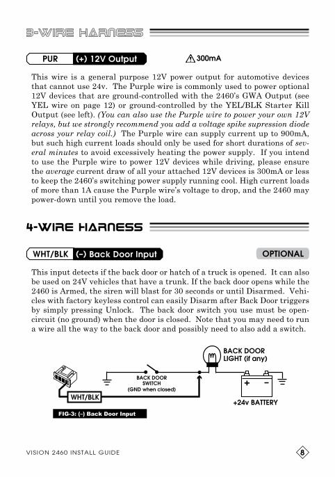
4-wire harness
PUR (+) 12V Output
WHT/BLK (–) Back Door Input OPTIONAL
300mA
This wire is a general purpose 12V power output for automotive devices that cannot use 24v. The Purple wire is commonly used to power optional 12V devices that are ground-controlled with the 2460’s GWA Output (see YEL wire on page 12) or ground-controlled by the YEL/BLK Starter Kill Output (see left). (You can also use the Purple wire to power your own 12V relays, but we strongly recommend you add a voltage spike supression diode across your relay coil.) The Purple wire can supply current up to 900mA, but such high current loads should only be used for short durations of sev-eral minutes to avoid excessively heating the power supply. If you intend to use the Purple wire to power 12V devices while driving, please ensure the average current draw of all your attached 12V devices is 300mA or less to keep the 2460’s switching power supply running cool. High current loads of more than 1A cause the Purple wire’s voltage to drop, and the 2460 may power-down until you remove the load.
This input detects if the back door or hatch of a truck is opened. It can also be used on 24V vehicles that have a trunk. If the back door opens while the 2460 is Armed, the siren will blast for 30 seconds or until Disarmed. Vehi-cles with factory keyless control can easily Disarm after Back Door triggers by simply pressing Unlock. The back door switch you use must be open-circuit (no ground) when the door is closed. Note that you may need to run a wire all the way to the back door and possibly need to also add a switch.
BACK DOORLIGHT (if any)
BACK DOORSWITCH
(GND when closed)
+24 v BATTERYFIG-3: (–) Back Door Input
WHT/BLK
3-wire harness

9 VISION 2460 INSTALL GUIDE
4-wire harness
This input connects to the vehicle’s Hazard (turn signal) lights and works in combination with the door Lock and Unlock inputs to inform the 2460 when to Arm/Disarm. See Fig-4 below.
Connect the WHT/RED wire as shown in Fig-4 above (also shown on the next page), between the vehicle’s Light Flash Unit and the turn signal light. The correct wire should show +24v when the turn signal light is illuminated.
WHT/RED (+)24v Hazard Light Input
This input normally connects to the Unlock wire between the “door lock relay control module” and the vehicle’s door lock actuator motors (see page 10). This input is vital for the 2460 to know when to Disarm.
BLU/YEL (+)24v Door UNLOCK Input
GRN/YEL (+)24v Door LOCK Input
This input normally connects to the Lock wire between the “door lock relay control module” and the vehicle’s door lock actuator motors (see page 10). This input is vital for the 2460 to know when to Arm.
All 3 connections on this page are very important. Connecting them incorrectly will result in malfunction of the 2460. NEVER use electrotaps! Only use PosiTap connectors. Use solder only if you are experienced.
WARNING!
FIG-4: Connecting the Hazard Light Input

10© 2018 KIRAMEK, INC.
4-wire harness
Driver’s Door Lock Motor
Passenger’s Door Lock Motor
Never connect to the LOCK/UNLOCK wires between Door Lock Switch & Relay Module!
For most vehicles, connect to the wires at the motor. Polarity must be (+)24v!
(+)24v BLU/YEL (UNLOCK input)
(+)24v GRN/YEL (LOCK input)
Door Lock SW
Door LockRelay Control
Module
FACTORY KEYLESSMODULE
LOCK UNLOCK
4-wireHarness
LOCK
UNLOCK
RIGHTTurn Signal
Lights
LEFTTurn Signal
Lights
TIP: It doesn’t matter ifyou connect to the LEFTor RIGHT sides.
(+)24v WHT/RED (HAZARD LAMP input)
(–) WHT/BLK Back Door input(see page 8)
Vehicle Light FlashRelay Module
LEFT RIGHT
NOTE: “Turn Signal” lights are defined as “Hazard” lights in this manual.
NOTE: Leave the 2460’s WHT/RED “Hazard Input” wire disconnected if connecting to the LOCK/UNLOCK wires between the Factory Keyless Module and the Door Lock Relay Control Module. • Must be (+)24v polarity. • Not possible with most vehicles.
+ +

11 © 2018 KIRAMEK, INC.11
6-wire main harness
This wire must be connected to the (+)24v Ignition line (showing 24v when IG switch is turned on). The connection of this wire is vi-tal for triggering the horn/siren if the Ignition goes on while Armed, and for Manual Disarm-ing. The Ignition input is also required if you
wish to sleep in the vehicle with the engine running and also wish to Arm the 2460.
GRN/WHT (+)24v Ignition Input
The RED wire is the (+)24v power input to the 2460. Be sure to connect this wire securely to a constant 24v source, such as the factory wire attached to Pin-16 of the vehicle’s OBD2 connec-tor. NEVER attach multiple high-current devic-
es to the same (+)24v connection point, as those devices may cause a large voltage dip that could cause the 2460 to malfunction.
RED (+)24v System Power
BATTERYRED
IGNITIONSWITCH
OFF
ACC
ON ST
GRN/WHT
The BLACK wire is the primary (–) Ground of the 2460. Be sure to connect this wire securely to a good ground source. Most security system installation problems result from a bad ground connection! The easiest connection may be to the factory wire behind Pin-4 of
the vehicle’s OBD connector. Of course, you can connect to body metal or an existing bolt (brush with steel wool first to make the best electrical contact). Running a wire directly to the car’s Negative battery terminal is allowed if you use thick wire, but it’s best to keep the ground as short as possible by connecting to body metal nearest the 2460 control module.
BLK (–) System Ground
VEHICLEGROUND
BLK

12VISION 2460 INSTALL GUIDE
6-wire main harness
WHT (–) Door Input
YEL (–) GWA Output
This input wire detects if a Door (usually one of the two front doors of a truck)is opened. If opened while the 2460 is Armed, the horn/siren will blast for up to 30 seconds. Wiring is shown below in Fig-5. Door switches must be open-ciruit and not supplying (–)GND when the Door is closed.
In situations where you need the WHT wire to connect to multiple loca-tions, adding multiple diodes to the WHT wire can be tedious and prone to error. We therefore recommend the optional DSS-6 (1-to-6 splitter) to make installation faster and error free. When using the DSS-6, please refer to its product manual instead of Fig-5 above.
We don’t recommend using the WHT wire for the Back Door of a long trailer because the WHT/BLK wire, described on page 8, is intended for that purpose. If do you connect the WHT wire to the Back Door, you can-not easily disarm with a mere press on factory keyless Unlock.
IMPORTANT!
FIG-5: Door/Trunk wiring
Supplies (–)0v ground (0.7A max., NPN transistor) while the 2460 is Armed. Shuts off attached devices when the 2460 is disarmed. Connect as shown in Fig.6 below.
700mA OPTIONAL
FIG-6: GWA control of LED Scanners
YEL
RED
BLK
YEL
PUR(+)12V
(+)12V
13 VISION 2460 INSTALL GUIDE13
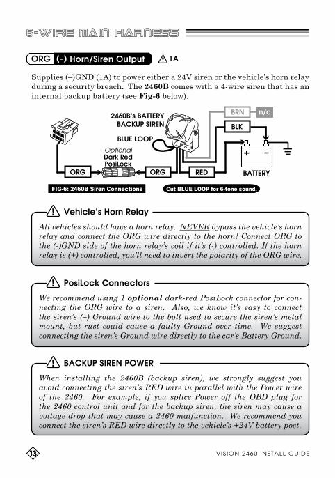
Supplies (–)GND (1A) to power either a 24V siren or the vehicle’s horn relay during a security breach. The 2460B comes with a 4-wire siren that has an internal backup battery (see Fig-6 below).
ORG (–) Horn/Siren Output
All vehicles should have a horn relay. NEVER bypass the vehicle’s horn relay and connect the ORG wire directly to the horn! Connect ORG to the (-)GND side of the horn relay’s coil if it’s (-) controlled. If the horn relay is (+) controlled, you’ll need to invert the polarity of the ORG wire.
Vehicle’s Horn Relay
We recommend using 1 optional dark-red PosiLock connector for con-necting the ORG wire to a siren. Also, we know it’s easy to connect the siren’s (–) Ground wire to the bolt used to secure the siren’s metal mount, but rust could cause a faulty Ground over time. We suggest connecting the siren’s Ground wire directly to the car’s Battery Ground.
PosiLock Connectors
When installing the 2460B (backup siren), we strongly suggest you avoid connecting the siren’s RED wire in parallel with the Power wire of the 2460. For example, if you splice Power off the OBD plug for the 2460 control unit and for the backup siren, the siren may cause a voltage drop that may cause a 2460 malfunction. We recommend you connect the siren’s RED wire directly to the vehicle’s +24V battery post.
BACKUP SIREN POWER
6-wire main harness
Cut BLUE LOOP for 6-tone sound.
OptionalDark RedPosiLock
BLUE LOOP
FIG-6: 2460B Siren Connections
ORG
2460B’s BATTERYBACKUP SIREN
ORG
BRN
1A

14© 2018 KIRAMEK, INC.
Unlike the 2460 control module and sensors, the Siren is to be mounted outside the cabin to be easy to hear outside. You must run a wire from the 2460’s control module (mounted inside the cabin) to the Siren’s ORG wire. It may be best to find a location near the vehicle’s batteries which is far from heat sources or moving parts or fans. Try to find a factory bolt or bolt hole for securing the siren mount; otherwise, you will need to drill holes yourself. The siren is water-resistant but it cannot be submerged, so avoid mounting the siren in places where water can pool or constantly pour over siren.
MOUNTING THE SIREN
As is true with all batteries, the battery inside the 2460B’s backup siren has a finite life. Life varies based on the installed environment. Typical life in the engine compartment is 3 years, under a constant trickle charge of 5.5mA. The battery is warrantied for 1 year. You cannot replace the battery inside the siren because it is glued, but the siren will continue to operate even after the battery is dead (you simply will lose the backup func-tion). The replacement part number for the battery backup siren is KB24-1.
BACKUP BATTERY
6-wire main harness
2460B
The 2460B comes with a Battery Backup Siren and two siren keys. At the factory, the siren is Disabled so it will not make any sound until you Enable it by switching the keylock to the GREEN dot position, as shown at right.
Keep the siren Disabled until you have made all your con-nections, otherwise the siren may blast.
Be sure to keep your keys in two separate safe places because you cannot order replacement keys! You will need a key if the siren goes off for some reason and you cannot shut it off by normal means (e.g., you cannot use Unlock with your factory remote to stop the siren blast if the vehicle’s main battery power is disconnected).
BACKUP SIREN KEYS
Enabled
RED dotGRN dot
Disabled
RED dotGRN dot
2460B
2460B

15 © 2018 KIRAMEK, INC.
MOUNTING SYSTEM COMPONENTS
The Control Module is “the brain” of the system and therefore must be installed in a secure location under the dash. NEVER install the Control Module in the engine area or near any source of heat or moisture! NEVER place the Control Module near moving parts or in a location where it can vibrate or be kicked or move around excessively.
Locations above or behind the glove box, behind the radio or high up under the dash are all good mounting places. However, you may need to extend wires if your chosen location is too far from the steering column. If you extend wires, always use the same or larger gauge wire! Solder all large gauge wire connections and cover with electrical tape or heat shrink tubing and/or corrugate tube. Mount the control module to a secure, flat surface or use wire ties to affix to a factory wire harness.
Control Module
When considering an appropriate mounting location, keep in mind that most thieves hot-wire vehicles by removing the plastic panel just under the steering column.
NOTE
LED Program Switch
The Status LED is used as a visual theft deterrent when the system is Armed and to alert the user if the siren triggered in their absence. Both the LED and the Program Switch are used for feature programming.
This unit is the size of a factory switch cover, so you can easily mount it with the included 2-sided tape somewhere near the steering wheel. Mount it so the LED can be seen from outside the driver’s side window. Such will warn would-be thieves and conveniently show you the Trigger Memory.

16VISION 2460 INSTALL GUIDE
mounting system components
The shock sensor is not waterproof so only mount it inside the cabin. Only use the included 2-sided tape, and mount the sensor to the outside of a plastic surface such as the car’s center console. We recommend you mount it in open view (rather than hide it) in order to make sensitivity adjust-ments easier.
When chosing a mounting location on the driv-er’s side (typically on the lower side of the center console plastics), try to mount the sensor in a place where it cannot be accidentally kicked by the driver or hit by the seat. And before you mount the sensor with the included tape, use your fingers to press against the place where you want to mount it, to see if the plastics move a lot when you press on them. Plastics that are “looser” will result in lower shock sensitivity. Mounting on a more firm section of the car’s plastic will result in greater sensitivity. Since you only have one piece of included tape, try to determine the best mounting location before you affix it.
NEVER use screws or wire ties to mount the sensor! Always mount to plastic, using the included tape! Mounting to metal can increase sensitiv-ity so high it will cause false triggering.
We strongly recommend you first clean the mounting surface in the car with brake cleaner (or similar oil solvent, degreaser) to make the sensor’s 2-sided tape stick more permanently. Even when affixing the sensor to very rough textured car plastics, the use of brake cleaner on the plastic surface will allow the sensor tape to stick permanently. Failure to clean the surface may result in the tape peeling off over time, which would cause the sensor to fall off and possible false trigger the siren.
Shock Sensor
Always mount the shock sensor and sensor wires more than 30cm (1ft.) away from the optional Paging System’s Antenna Unit, and 30cm from the optional Ultrasonic Sensor’s controller. Failure to do so may cause the shock sensor to randomly false trigger the siren.
NOTE
VISIONIR SHOCK SENSOR
GOOD
2460B

17 VISION 2460 INSTALL GUIDE
TUNG
25 v
TUNG
TUNG
25v 25v
504
R5
R3
R8
Q2
C10
D7
C12
318
REV1
052
C5 C6
R19
R13
C3
C9
R2R4
LM324 41C831N
R18
25 v
TUNG
TUNG
TUNG
25v 25v
25v
504
R5
R3
R8
Q2
C10
D7
C12
318
REV1
052
C5 C6
R19
C4R13
C3
C9
R2R4
LM324 41C831N
R18
TUNG
25 v
TUNG
TUNG
25v 25v
504
R5
R3
R8
Q2
C10
D7
C12
318
REV1
052
C5 C6
R19
R13
C3
C9
R2R4
LM324 41C831N
ADJUSTING THE SHOCK SENSOR
The shock sensor is factory preset to work well with most vehicles out-of-the-box (50% setting). Howev-er, if you find that the siren is going off too easily, or if the siren doesn’t go off when you think it should, it’s time to adjust the sensitivity.
Turn the sensitivity adjustment knob clockwise to increase sensitivity and counter-clockwise to decrease. If you cannot find a suitable adjustment level, consider remounting the shock sensor.
Sensitivity
The VISION 318-052 Active-IR shock sensor has been engineered to avoid false triggers in most situations. However, there is still the possibility the sensor could trigger the siren during a strong earthquake, jackham-mer operation adjacent to the vehicle, hurricane/typhoon, large explosions/fireworks, large animals ramming against the vehicle, etc. If any of these extreme cases are anticipated, you can avoid false siren triggers simply by Arming the system with the Sensor Bypass Arming, which ignores the shock sensor (see page 3 of the Owner’s Guide).
Another consideration is temperature. The sensitivity can vary by as much as 20% under extreme temperature conditions. You may wish to reduce the sensitivity in very hot weather and increase sensitivity in very cold weather.
False Alarms
If the shock sensor is not working well or at all, it may be that the sus-pended element inside the case was jolted out of position. Disconnect the wire harness, snap open the shock sensor case, and adjust as shown below.
Suspended Reflector Malfunction
Full TriggerRED LED
Warning TriggerGREEN LED
SensitivityAdjustment
VISIONIR SHOCK SENSOR
SENSITIVITYADJUST
Incorrect AlignmentCorrect Alignment
2460B
2460B
2460B

18© 2018 KIRAMEK, INC.
TROUBLESHOOTING
HORN/SIREN CHIRPS 5 TIMES AFTER I UNLOCK!• It could be your truck’s battery voltage is low. Check voltage level.
• Did you use SPLICE CLIPS for your connections? If so, remove and use PosiTaps. Splice Clips should not be used with the 2460 since (a) they come loose over time and (b) any slight jolt to the door lock signal wires may cause a read error resulting in unexpected operation.
• If you soldered your connections, it could be that you connected the 2460’s WHITE wire to the wrong location. Please refer to Fig-5 on page 12 and note the Vehicle Computer. You must make your WHITE wire connection BETWEEN the Vehicle Computer (if there is one) and the lights shown. If you made your connection between the computer and the switch, the 2460 will not operate properly! If the WHITE wire is not connected correctly, you will sometimes hear 5 chirps when you Disarm, even though the siren did not go off in your absence and even though you are not triggering the 2460B’s shock sensor.
• If you used solder, you very likely made a bad connection (i.e., a Cold solder joint). You may need to recheck your wiring. We recommend solder only for installers experienced using it in automotive electron-ics. For everyone else, we strongly recommend optional Posi-Tap and Posi-Lock connectors.
• If you connected to more than just the 2 doors, did you diode-isolate each of your connections to the WHT wire or use the optional DSS-6? If not, that could be the problem.
• If the above doesn’t help, try the RESET procedure on page 14 of the Owner’s Guide.
• Lastly, it is important to remember that if the horn/siren went off in your absence, the horn/siren will chirp 4 times when you return to the vehicle and disarm the system. This is proper operation of the 2460. You can also see which zone was triggered by examining the Status LED flashes upon your return to the vehicle (see page 9 of the Owner’s Guide).
SHOCK SENSOR ONLY “FULL TRIGGERS.” THERE’S NO WARNING TRIGGER.• View the sensor’s LEDs when you hit the car’s body. If the Green LED
doesn’t light, slightly increase the sensitivity of the shock sensor. • If the Green LED lights, perhaps you’re testing too quickly. After
Locking/Arming, you must wait 10s before you can test the shock sen-sor. And after each trigger, you must wait 8 seconds before you test another trigger.

19 © 2018 KIRAMEK, INC.
TROUBLESHOOTING
SHOCK SENSOR GIVES REPEATED WARNING TRIGGERS.• If the sensitivity of the sensor is too high and/or if the mounting location
is incorrect, the sensor may be triggering on the otherwise undetectable sounds of the hazard light relay switching, or even the siren vibration. Reduce sensitivity and/or change the mounting location of the sensor.
• Another cause of shock sensor false triggers pertains to the shock sensor 4-wire harness. Make sure no other wires are touching or in close prox-imity to the shock sensor wires. Also make sure there is no RF trans-mitter device is very close proximity to the shock sensor wires.
HORN/SIREN NEVER SOUNDS.• If using the 2460B’s siren, re-check your wiring as per page 13.• If using the 2460B’s siren, ensure the siren’s keylock is switched ON.• If you were trying to connect to the vehicle’s horn, you may have con-
nected to the wrong location or have the wrong polarity. It’s also pos-sible you bypassed the vehicle’s horn relay and instead connected to the Horn itself, which would draw too much power. The 2460’s (–) Horn/Siren output can supply 1A, which is not enough for most 5A air horns. The Horn/Siren output has an internal PTC fuse to protect the circuit, but the fuse will need time to cool if blown. It is also possible the PTC fuse was damaged. You can determine that by testing the Horn/Siren output without any load attached. If you find there is no (-) Ground when you trigger the horn/siren, the fuse could be bad and in that case you would need to return the control module to KIRAMEK for repair.
INSTALLATION IS FINISHED BUT 2460 WON’T WORK CORRECTLY.• Check what is connected to the 2460’s PUR 12V output wire. If the
attached load draws more than 1A, the PUR wire’s output voltage will drop and if it drops too low the CPU inside the control module will stop working until that high current load is disconnected.
• If you purchased an optional transmitter kit, do you have the antenna unit’s 3-wire harness properly connected to the BLK 3-pin connector on the back of the 2460 control module? Never connect it to the WHT 3-pin connector on the front of the control module!
• It could be the system is working but there is a problem with your Horn/Siren output connection. Arm the system and check the status LED. If it starts flashing, that is proof the system is Armed and working. It also could be you are trying to test the shock sensor with either the sensor disconnected or the sensitivity turned off.
• If the vehicle battery voltage is too low, the 2460 will cease working. However, the 2460 and attached sensors and transmitters are designed to function even when the battery voltage falls as low as 8.5V.

20VISION 2460 INSTALL GUIDE
OPTIONS
The 2460 can be installed in your truck without the need for any Options. However, we do offer the following add-on products to enhance security and convenience:
TR537S: 2-way LCD RF Paging Control System (ARIB-T67, for Japan) TR365S: 1-way 3-button Transmitter (1pc kit) (RF Certified for Japan)TR365D: 1-way 3-button Transmitter (2pc kit) (RF Certified for Japan)
S-114R or S-113: Pin switch to detect a hatch opening.
Optional Sensors: • 318-052: 2-stage Shock Sensor (not included with the 2460H)• 318-054: 2-stage Shock Sensor with 2 indepedent adjustments.• MMF-2: 2-stage Radar Sensor• KST-24: 2-stage Digital Tilt Sensor• SB-03: Sensor Splitter to easily connect up to 3 sensors at once
Luminator® LED Scanners – visual theft deterrents
More details about add-on devices can be found on our website:www.visionsecurity.jp/en/

9-183-1 I tayama-cho, Handa-shi , Aichi-Ken 475-0936 JAPANTEL: +81-569-20-5585 • FAX: +81-569-20-5586 • EMAIL: [email protected]
VISION products are engineered in Japan and manufactured in strict accordance with Japanese QC standards at an ISO9000/QS9000 certified factory.