VisiLogic Examples - Elmark VisiLogic Examples 5 HMI- General These applications show a number of...
29
i VisiLogic Examples Help Version: 2/12/04 Table Of Contents About VisiLogic Examples ............................................................................................................... 1 Beginner's applications............................................................................................................. 1 Advanced Applications ............................................................................................................. 4 HMI- General ............................................................................................................................ 5 Display Shows .......................................................................................................................... 6 HMI- General ............................................................................................................................ 7 Touch........................................................................................................................................ 8 About Communications ............................................................................................................ 9 CANbus .................................................................................................................................... 9 FB Protocol-serial ................................................................................................................... 10 GPRS ..................................................................................................................................... 11 MODBUS-Serial ..................................................................................................................... 12 MODBUS IP (Ethernet) .......................................................................................................... 13 SMS ........................................................................................................................................ 13 Data Table .............................................................................................................................. 14 Trends .................................................................................................................................... 15 Events..................................................................................................................................... 16 Flow and Totalizing ................................................................................................................ 17 High Speed Counters, Outputs, PWM ................................................................................... 17 Analog Output......................................................................................................................... 18 Loadcell .................................................................................................................................. 18 Math........................................................................................................................................ 19 PID.......................................................................................................................................... 19 Real-Time-Clock ..................................................................................................................... 20 UTC ........................................................................................................................................ 20 Strings .................................................................................................................................... 21 Timers..................................................................................................................................... 22 Interrupt .................................................................................................................................. 23 Vectors ................................................................................................................................... 23 Index .............................................................................................................................................. 27
-
Upload
duonghuong -
Category
Documents
-
view
234 -
download
2
Transcript of VisiLogic Examples - Elmark VisiLogic Examples 5 HMI- General These applications show a number of...
i
VisiLogic Examples Help Version: 2/12/04
Table Of Contents About VisiLogic Examples ............................................................................................................... 1
Beginner's applications............................................................................................................. 1 Advanced Applications ............................................................................................................. 4 HMI- General ............................................................................................................................ 5 Display Shows.......................................................................................................................... 6 HMI- General ............................................................................................................................ 7 Touch........................................................................................................................................ 8 About Communications ............................................................................................................ 9 CANbus .................................................................................................................................... 9 FB Protocol-serial ................................................................................................................... 10 GPRS ..................................................................................................................................... 11 MODBUS-Serial ..................................................................................................................... 12 MODBUS IP (Ethernet) .......................................................................................................... 13 SMS........................................................................................................................................ 13 Data Table .............................................................................................................................. 14 Trends .................................................................................................................................... 15 Events..................................................................................................................................... 16 Flow and Totalizing ................................................................................................................ 17 High Speed Counters, Outputs, PWM ................................................................................... 17 Analog Output......................................................................................................................... 18 Loadcell .................................................................................................................................. 18 Math........................................................................................................................................ 19 PID.......................................................................................................................................... 19 Real-Time-Clock..................................................................................................................... 20 UTC ........................................................................................................................................ 20 Strings .................................................................................................................................... 21 Timers..................................................................................................................................... 22 Interrupt .................................................................................................................................. 23 Vectors ................................................................................................................................... 23
Index .............................................................................................................................................. 27

1
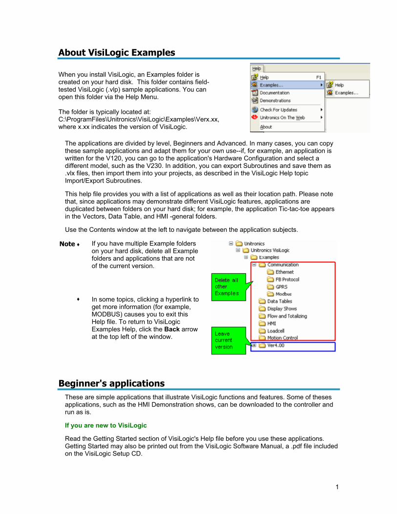
About VisiLogic Examples When you install VisiLogic, an Examples folder is created on your hard disk. This folder contains field-tested VisiLogic (.vlp) sample applications. You can open this folder via the Help Menu. The folder is typically located at: C:\ProgramFiles\Unitronics\VisiLogic\Examples\Verx.xx, where x.xx indicates the version of VisiLogic.
The applications are divided by level, Beginners and Advanced. In many cases, you can copy these sample applications and adapt them for your own use--if, for example, an application is written for the V120, you can go to the application's Hardware Configuration and select a different model, such as the V230. In addition, you can export Subroutines and save them as .vlx files, then import them into your projects, as described in the VisiLogic Help topic Import/Export Subroutines.
This help file provides you with a list of applications as well as their location path. Please note that, since applications may demonstrate different VisiLogic features, applications are duplicated between folders on your hard disk; for example, the application Tic-tac-toe appears in the Vectors, Data Table, and HMI -general folders.
Use the Contents window at the left to navigate between the application subjects.
Note ♦
If you have multiple Example folders on your hard disk, delete all Example folders and applications that are not of the current version.
♦ In some topics, clicking a hyperlink to get more information (for example, MODBUS) causes you to exit this Help file. To return to VisiLogic Examples Help, click the Back arrow at the top left of the window.
Beginner's applications These are simple applications that illustrate VisiLogic functions and features. Some of theses applications, such as the HMI Demonstration shows, can be downloaded to the controller and run as is.
If you are new to VisiLogic
Read the Getting Started section of VisiLogic's Help file before you use these applications. Getting Started may also be printed out from the VisiLogic Software Manual, a .pdf file included on the VisiLogic Setup CD.
VisiLogic Examples
2
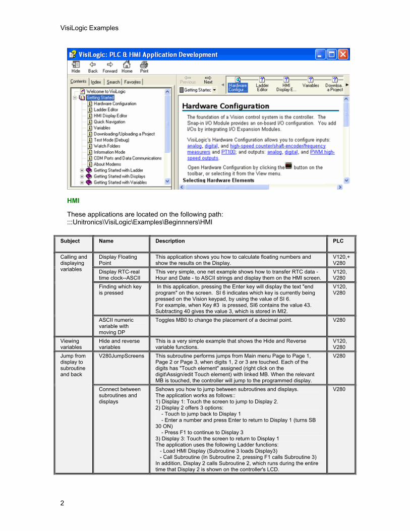
HMI
These applications are located on the following path: :::Unitronics\VisiLogic\Examples\Beginnners\HMI
Subject Name Description PLC
Display Floating Point
This application shows you how to calculate floating numbers and show the results on the Display.
V120,+ V280
Display RTC-real time clock--ASCII
This very simple, one net example shows how to transfer RTC data - Hour and Date - to ASCII strings and display them on the HMI screen.
V120, V280
Finding which key is pressed
In this application, pressing the Enter key will display the text "end program" on the screen. SI 6 indicates which key is currently being pressed on the Vision keypad, by using the value of SI 6. For example, when Key #3 is pressed, SI6 contains the value 43. Subtracting 40 gives the value 3, which is stored in MI2.
V120, V280
Calling and displaying variables
ASCII numeric variable with moving DP
Toggles MB0 to change the placement of a decimal point. V280
Viewing variables
Hide and reverse variables
This is a very simple example that shows the Hide and Reverse variable functions.
V120, V280
V280JumpScreens This subroutine performs jumps from Main menu Page to Page 1, Page 2 or Page 3, when digits 1, 2 or 3 are touched. Each of the digits has "Touch element" assigned (right click on the digit\Assign/edit Touch element) with linked MB. When the relevant MB is touched, the controller will jump to the programmed display.
V280 Jump from display to subroutine and back
Connect between subroutines and displays
Sshows you how to jump between subroutines and displays. The application works as follows:: 1) Display 1: Touch the screen to jump to Display 2. 2) Display 2 offers 3 options: - Touch to jump back to Display 1 - Enter a number and press Enter to return to Display 1 (turns SB 30 ON) - Press F1 to continue to Display 3 3) Display 3: Touch the screen to return to Display 1 The application uses the following Ladder functions: - Load HMI Display (Subroutine 3 loads Display3) - Call Subroutine (In Subroutine 2, pressing F1 calls Subroutine 3) In addition, Display 2 calls Subroutine 2, which runs during the entire time that Display 2 is shown on the controller's LCD.
V280
About VisiLogic Examples
3
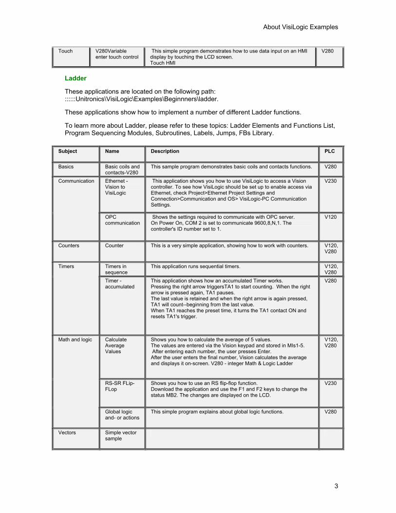
Touch V280Variable enter touch control
This simple program demonstrates how to use data input on an HMI display by touching the LCD screen. Touch HMI
V280
Ladder
These applications are located on the following path: ::::::Unitronics\VisiLogic\Examples\Beginnners\ladder.
These applications show how to implement a number of different Ladder functions.
To learn more about Ladder, please refer to these topics: Ladder Elements and Functions List, Program Sequencing Modules, Subroutines, Labels, Jumps, FBs Library.
Subject Name Description PLC
Basics Basic coils and contacts-V280
This sample program demonstrates basic coils and contacts functions. V280
Ethernet - Vision to VisiLogic
This application shows you how to use VisiLogic to access a Vision controller. To see how VisiLogic should be set up to enable access via Ethernet, check Project>Ethernet Project Settings and Connection>Communication and OS> VisiLogic-PC Communication Settings.
V230 Communication
OPC communication
Shows the settings required to communicate with OPC server. On Power On, COM 2 is set to communicate 9600,8,N,1. The controller's ID number set to 1.
V120
Counters Counter This is a very simple application, showing how to work with counters. V120, V280
Timers in sequence
This application runs sequential timers. V120, V280
Timers
Timer - accumulated
This application shows how an accumulated Timer works. Pressing the right arrow triggersTA1 to start counting. When the right arrow is pressed again, TA1 pauses. The last value is retained and when the right arrow is again pressed, TA1 will count--beginning from the last value. When TA1 reaches the preset time, it turns the TA1 contact ON and resets TA1's trigger.
V280
Calculate Average Values
Shows you how to calculate the average of 5 values. The values are entered via the Vision keypad and stored in MIs1-5. After entering each number, the user presses Enter. After the user enters the final number, Vision calculates the average and displays it on-screen. V280 - integer Math & Logic Ladder
V120, V280
RS-SR FLip-FLop
Shows you how to use an RS flip-flop function. Download the application and use the F1 and F2 keys to change the status MB2. The changes are displayed on the LCD.
V230
Math and logic
Global logic and- or actions
This simple program explains about global logic functions. V280
Vectors Simple vector sample
VisiLogic Examples
4
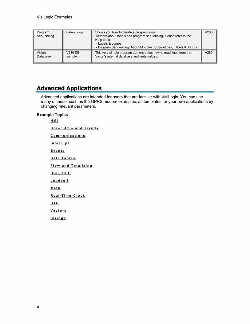
Program Sequencing
Label-Loop Shows you how to create a program loop. To learn about labels and program sequencing, please refer to the Help topics: - Labels & Jumps - Program Sequencing: About Modules, Subroutines, Labels & Jumps
V280
Vision Database
V280 DB sample
This very simple program demonstrates how to read lines from the Vision's internal database and write values.
V280
Advanced Applications Advanced applications are intended for users that are familiar with VisiLogic. You can use many of these, such as the GPRS modem examples, as templates for your own applications by changing relevant parameters.
Example Topics H M I
D r a w : A x i s a n d T r e n d s
C o m m u n i c a t i o n s
I n t e r r u p t
E v e n t s
D a t a T a b l e s
F l o w a n d T o t a l i z i n g
H S C , H S O
L o a d c e l l
M a t h
R e a l - T i m e - C l o c k
U T C
V e c t o r s
S t r i n g s
About VisiLogic Examples
5
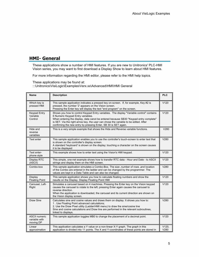
HMI- General
These applications show a number of HMI features. If you are new to Unitronics' PLC-HMI Vision series, you may want to first download a Display Show to learn about HMI features.
For more information regarding the HMI editor, please refer to the HMI help topics.
These applications may be found at: :::Unitronics\VisiLogic\Examples\Verx.xx\Advanced\HMI\HMI General
Name Description PLC
Which key is pressed HMI
This sample application indicates a pressed key on-screen. If, for example, Key #2 is pressed, the number '2' appears on the Vision screen. Pressing the Enter key will display the text "end program" on the screen.
V120
Keypad Entry Variable Control
Shows you how to control Keypad Entry variables. The display "Variable control" contains 6 Numeric Keypad Entry variables. When entering the display, data canot be entered because SB30 "Keypad entry complete" is SET. Via the right arrow key, the user can chose the variable to be edited. After confirming the new entry by pressing Enter, SB 30 is SET again.
V120
Hide and reverse variables
This is a very simple example that shows the Hide and Reverse variable functions. V280
Text enter This sample application enables you to use the controller's touch-screen to enter text that is shown on the controller's display screen. A standard 'keyboard' is shown on the display; touching a character on the screen causes it to be displayed
V280
Text enter-phone style
This example shows how to enter text using the Vision's HMI keypad. V120
Display RTC (ASCII)
This simple, one-net example shows how to transfer RTC data - Hour and Date - to ASCII strings and display them on the HMI screen.
V120
Combo-box This sample application simulates a Combo-Box. The size ,number of rows ,and location of the Combo are entered in the ladder and can be changed by the programmer. The values are kept in a Data Table and can also be changed.
V280
Display Floating Point
This sample application shows you how to calculate floating numbers and show the results on the Display. Display Floating Point HMI
V120
Carousel, Left-Right
Simulates a carousel based on 4 machines. Pressing the Enter key on the Vision keypad causes the carousel to rotate to the left; pressing Enter again causes the carousel to reverse direction. When the application is downloaded, the carousel and its current direction are shown on the Vision display screen.
V120
Draw Sine Calculates sine and cosine values and draws them on display. It shows you how to: 1 . Use Floating Point advanced calculations; 2. Use the Draw Pixel utility (Ladder\HMI menu) to draw the sine/cosine line Sine and cosine calculations and Draw line are performed in the relevant subroutines, linked to displays.
V280
ASCII numeric variable with moving DP
This sample application toggles MB0 to change the placement of a decimal point. V120
Linear approximation
This application calculates a Y value on a non-linear X-Y graph. The graph in this application is divided into 11 points. The X and Y-coordinates of these points are stored in
V120, V280
VisiLogic Examples
6
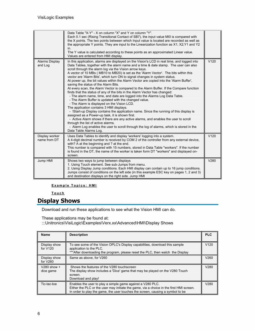
Data Table "X-Y" - X on column "X" and Y on column "Y". Each 0.1 sec (Rising Transitional Contact of SB7), the input value MI0 is compared with the X points. The two points between which Input value is located are recorded as well as the appropriate Y points. They are input to the Linearization function as X1; X2;Y1 and Y2 in. The Y value is calculated according to these points as an approximated Linear value. Values are entered from HMI display.
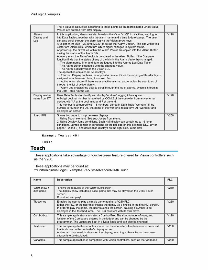
Alarms Display and Log
In this application, alarms are displayed on the Vision's LCD in real time, and logged into Data Tables, together with the alarm name and a time & date stamp. The user can also scroll through the alarm log via the Vision arrow keys. A vector of 10 MBs ( MB10 to MB20) is set as the 'Alarm Vector'. The bits within this vector are 'Alarm Bits', which turn ON to signal changes in system status. At power up, the bit values within the Alarm Vector are copied into the 'Alarm Buffer', saving the status of the Alarm Bits. At every scan, the Alarm Vector is compared to the Alarm Buffer. If the Compare function finds that the status of any of the bits in the Alarm Vector has changed: - The alarm name, time, and date are logged into the Alarms Log Data Table. - The Alarm Buffer is updated with the changed value. - The Alarm is displayed on the Vision LCD. The application contains 3 HMI displays. - !Start-up Display contains the application name. Since the running of this display is assigned as a Power-up task, it is shown first. - Active Alarm shows if there are any active alarms, and enables the user to scroll through the list of active alarms. - Alarm Log enables the user to scroll through the log of alarms, which is stored in the Data Table Alarms Log.
V120
Display worker name from DT
Uses Data Tables to identify and display 'workers' logging into a system. A 4-digit decimal number is received by COM 2 of the controller from any external device, with? A at the beginning and ? at the end. This number is compared with 15 numbers, stored in Data Table "workers". If the number is found in the DT, the name of the worker is taken form DT "workers" and displayed on-screen.
V120
Jump HMI Shows two ways to jump between displays 1. Using Touch element. See sub-Jumps from menu. 2. Using Display Jump conditions. Each HMI display can contain up to 16 jump conditions. Jumps consist of conditions on the left side (in this example ESC key on pages 1, 2 and 3) and destination displays on the right side. Jump HMI
V280
E x a m p l e T o p i c s : H M I
T o u c h
Display Shows Download and run these applications to see what the Vision HMI can do.
These applications may be found at: :::Unitronics\VisiLogic\Examples\Verx.xx\Advanced\HMI\Display Shows
Name Description PLC
Display show for V120
To see some of the Vision OPLC's Display capabilities, download this sample application to the PLC. ***After downloading the program, please reset the PLC, then watch the Display
V120
Display show for V260
Same as above, for V260 V260
V280 show + dice game
Shows the features of the V280 touchscreen The display show includes a 'Dice' game that may be played on the V280 Touch screen. Download and play!
V280
Tic-tac-toe Enables the user to play a simple game against a V280 PLC. Either the PLC or the user may initiate the game, via a choice in the first HMI screen. In order to play the game, the user touches the screen, causing a symbol to be
V280
About VisiLogic Examples
7
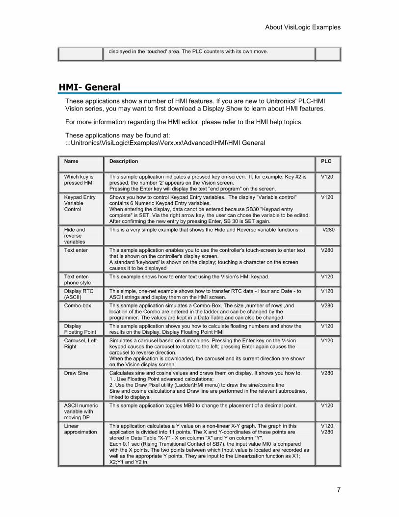
displayed in the 'touched' area. The PLC counters with its own move.
HMI- General These applications show a number of HMI features. If you are new to Unitronics' PLC-HMI Vision series, you may want to first download a Display Show to learn about HMI features.
For more information regarding the HMI editor, please refer to the HMI help topics.
These applications may be found at: :::Unitronics\VisiLogic\Examples\Verx.xx\Advanced\HMI\HMI General
Name Description PLC
Which key is pressed HMI
This sample application indicates a pressed key on-screen. If, for example, Key #2 is pressed, the number '2' appears on the Vision screen. Pressing the Enter key will display the text "end program" on the screen.
V120
Keypad Entry Variable Control
Shows you how to control Keypad Entry variables. The display "Variable control" contains 6 Numeric Keypad Entry variables. When entering the display, data canot be entered because SB30 "Keypad entry complete" is SET. Via the right arrow key, the user can chose the variable to be edited. After confirming the new entry by pressing Enter, SB 30 is SET again.
V120
Hide and reverse variables
This is a very simple example that shows the Hide and Reverse variable functions. V280
Text enter This sample application enables you to use the controller's touch-screen to enter text that is shown on the controller's display screen. A standard 'keyboard' is shown on the display; touching a character on the screen causes it to be displayed
V280
Text enter-phone style
This example shows how to enter text using the Vision's HMI keypad. V120
Display RTC (ASCII)
This simple, one-net example shows how to transfer RTC data - Hour and Date - to ASCII strings and display them on the HMI screen.
V120
Combo-box This sample application simulates a Combo-Box. The size ,number of rows ,and location of the Combo are entered in the ladder and can be changed by the programmer. The values are kept in a Data Table and can also be changed.
V280
Display Floating Point
This sample application shows you how to calculate floating numbers and show the results on the Display. Display Floating Point HMI
V120
Carousel, Left-Right
Simulates a carousel based on 4 machines. Pressing the Enter key on the Vision keypad causes the carousel to rotate to the left; pressing Enter again causes the carousel to reverse direction. When the application is downloaded, the carousel and its current direction are shown on the Vision display screen.
V120
Draw Sine Calculates sine and cosine values and draws them on display. It shows you how to: 1 . Use Floating Point advanced calculations; 2. Use the Draw Pixel utility (Ladder\HMI menu) to draw the sine/cosine line Sine and cosine calculations and Draw line are performed in the relevant subroutines, linked to displays.
V280
ASCII numeric variable with moving DP
This sample application toggles MB0 to change the placement of a decimal point. V120
Linear approximation
This application calculates a Y value on a non-linear X-Y graph. The graph in this application is divided into 11 points. The X and Y-coordinates of these points are stored in Data Table "X-Y" - X on column "X" and Y on column "Y". Each 0.1 sec (Rising Transitional Contact of SB7), the input value MI0 is compared with the X points. The two points between which Input value is located are recorded as well as the appropriate Y points. They are input to the Linearization function as X1; X2;Y1 and Y2 in.
V120, V280
VisiLogic Examples
8
The Y value is calculated according to these points as an approximated Linear value. Values are entered from HMI display.
Alarms Display and Log
In this application, alarms are displayed on the Vision's LCD in real time, and logged into Data Tables, together with the alarm name and a time & date stamp. The user can also scroll through the alarm log via the Vision arrow keys. A vector of 10 MBs ( MB10 to MB20) is set as the 'Alarm Vector'. The bits within this vector are 'Alarm Bits', which turn ON to signal changes in system status. At power up, the bit values within the Alarm Vector are copied into the 'Alarm Buffer', saving the status of the Alarm Bits. At every scan, the Alarm Vector is compared to the Alarm Buffer. If the Compare function finds that the status of any of the bits in the Alarm Vector has changed: - The alarm name, time, and date are logged into the Alarms Log Data Table. - The Alarm Buffer is updated with the changed value. - The Alarm is displayed on the Vision LCD. The application contains 3 HMI displays. - !Start-up Display contains the application name. Since the running of this display is assigned as a Power-up task, it is shown first. - Active Alarm shows if there are any active alarms, and enables the user to scroll through the list of active alarms. - Alarm Log enables the user to scroll through the log of alarms, which is stored in the Data Table Alarms Log.
V120
Display worker name from DT
Uses Data Tables to identify and display 'workers' logging into a system. A 4-digit decimal number is received by COM 2 of the controller from any external device, with? A at the beginning and ? at the end. This number is compared with 15 numbers, stored in Data Table "workers". If the number is found in the DT, the name of the worker is taken form DT "workers" and displayed on-screen.
V120
Jump HMI Shows two ways to jump between displays 1. Using Touch element. See sub-Jumps from menu. 2. Using Display Jump conditions. Each HMI display can contain up to 16 jump conditions. Jumps consist of conditions on the left side (in this example ESC key on pages 1, 2 and 3) and destination displays on the right side. Jump HMI
V280
E x a m p l e T o p i c s : H M I
T o u c h
Touch These applications take advantage of touch-screen feature offered by Vision controllers such as the V280.
These applications may be found at: :::Unitronics\VisiLogic\Examples\Verx.xx\Advanced\HMI\Touch
Name Description PLC
V280 show + dice game
Shows the features of the V280 touchscreen The display show includes a 'Dice' game that may be played on the V280 Touch screen. Download and play!
V280
Tic-tac-toe Enables the user to play a simple game against a V280 PLC. Either the PLC or the user may initiate the game, via a choice in the first HMI screen. In order to play the game, the user touches the screen, causing a symbol to be displayed in the 'touched' area. The PLC counters with its own move.
V280
Combo-box This sample application simulates a Combo-Box. The size, number of rows, and location of the Combo are entered in the ladder and can be changed by the programmer. The values are kept in a Data Table and can also be changed.
V120
Text enter This sample application enables you to use the controller's touch-screen to enter text that is shown on the controller's display screen. A standard 'keyboard' is shown on the display; touching a character on the screen causes it to be displayed.
V280
Variables- This sample application is compatible with Vision controllers, such as the V280 and V280
About VisiLogic Examples
9
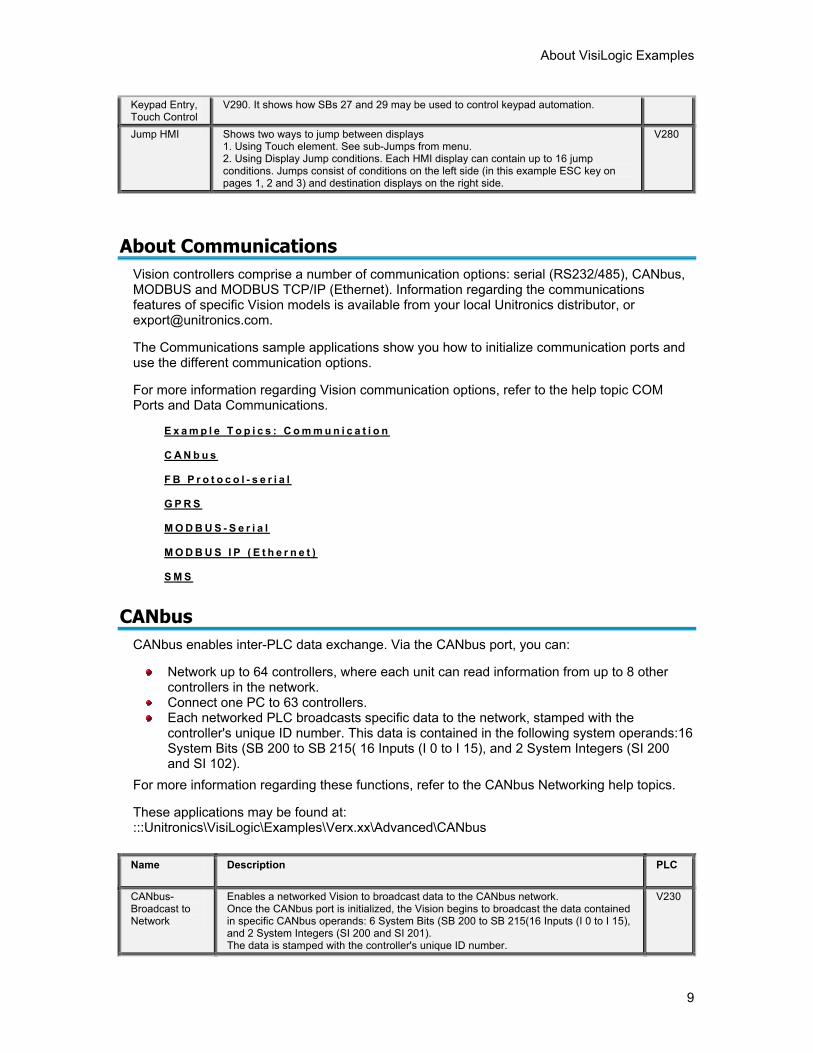
Keypad Entry, Touch Control
V290. It shows how SBs 27 and 29 may be used to control keypad automation.
Jump HMI Shows two ways to jump between displays 1. Using Touch element. See sub-Jumps from menu. 2. Using Display Jump conditions. Each HMI display can contain up to 16 jump conditions. Jumps consist of conditions on the left side (in this example ESC key on pages 1, 2 and 3) and destination displays on the right side.
V280
About Communications Vision controllers comprise a number of communication options: serial (RS232/485), CANbus, MODBUS and MODBUS TCP/IP (Ethernet). Information regarding the communications features of specific Vision models is available from your local Unitronics distributor, or [email protected].
The Communications sample applications show you how to initialize communication ports and use the different communication options.
For more information regarding Vision communication options, refer to the help topic COM Ports and Data Communications.
E x a m p l e T o p i c s : C o m m u n i c a t i o n
C A N b u s
F B P r o t o c o l - s e r i a l
G P R S
M O D B U S - S e r i a l
M O D B U S I P ( E t h e r n e t )
S M S
CANbus
CANbus enables inter-PLC data exchange. Via the CANbus port, you can:
Network up to 64 controllers, where each unit can read information from up to 8 other controllers in the network.
Connect one PC to 63 controllers. Each networked PLC broadcasts specific data to the network, stamped with the
controller's unique ID number. This data is contained in the following system operands:16 System Bits (SB 200 to SB 215( 16 Inputs (I 0 to I 15), and 2 System Integers (SI 200 and SI 102).
For more information regarding these functions, refer to the CANbus Networking help topics.
These applications may be found at: :::Unitronics\VisiLogic\Examples\Verx.xx\Advanced\CANbus
Name Description PLC
CANbus- Broadcast to Network
Enables a networked Vision to broadcast data to the CANbus network. Once the CANbus port is initialized, the Vision begins to broadcast the data contained in specific CANbus operands: 6 System Bits (SB 200 to SB 215(16 Inputs (I 0 to I 15), and 2 System Integers (SI 200 and SI 201). The data is stamped with the controller's unique ID number.
V230
VisiLogic Examples
10
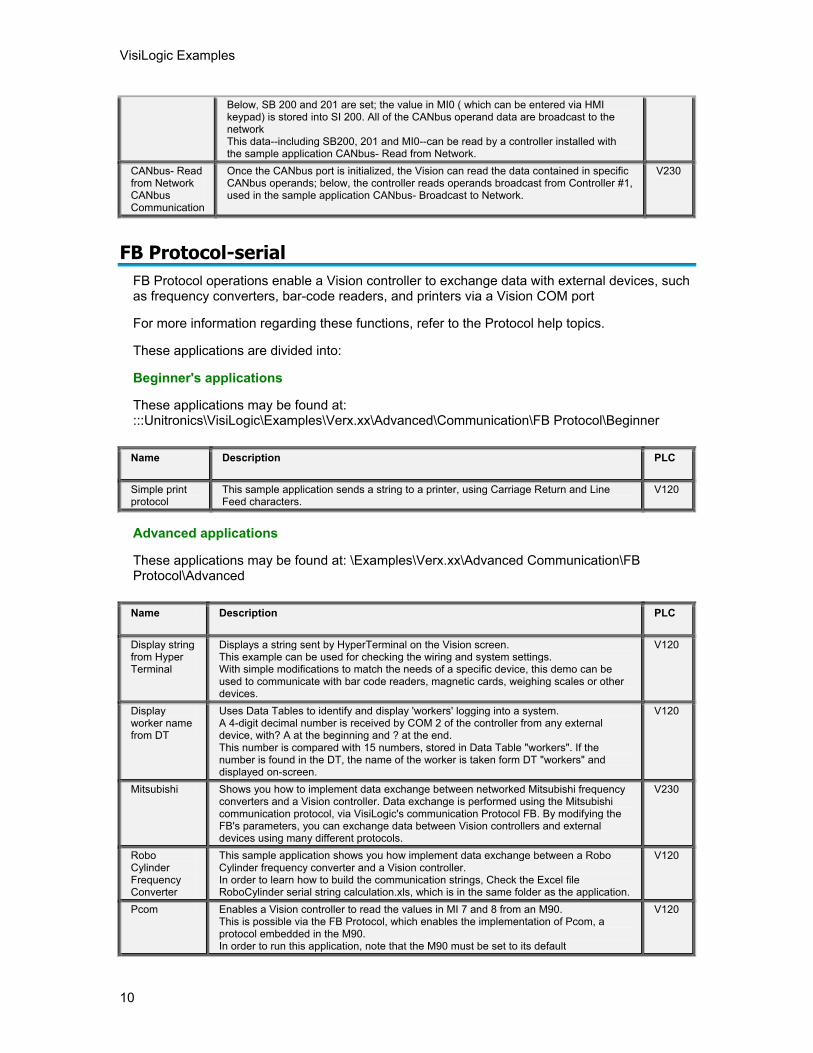
Below, SB 200 and 201 are set; the value in MI0 ( which can be entered via HMI keypad) is stored into SI 200. All of the CANbus operand data are broadcast to the network This data--including SB200, 201 and MI0--can be read by a controller installed with the sample application CANbus- Read from Network.
CANbus- Read from Network CANbus Communication
Once the CANbus port is initialized, the Vision can read the data contained in specific CANbus operands; below, the controller reads operands broadcast from Controller #1, used in the sample application CANbus- Broadcast to Network.
V230
FB Protocol-serial
FB Protocol operations enable a Vision controller to exchange data with external devices, such as frequency converters, bar-code readers, and printers via a Vision COM port
For more information regarding these functions, refer to the Protocol help topics.
These applications are divided into:
Beginner's applications
These applications may be found at: :::Unitronics\VisiLogic\Examples\Verx.xx\Advanced\Communication\FB Protocol\Beginner
Name Description PLC
Simple print protocol
This sample application sends a string to a printer, using Carriage Return and Line Feed characters.
V120
Advanced applications
These applications may be found at: \Examples\Verx.xx\Advanced Communication\FB Protocol\Advanced
Name Description PLC
Display string from Hyper Terminal
Displays a string sent by HyperTerminal on the Vision screen. This example can be used for checking the wiring and system settings. With simple modifications to match the needs of a specific device, this demo can be used to communicate with bar code readers, magnetic cards, weighing scales or other devices.
V120
Display worker name from DT
Uses Data Tables to identify and display 'workers' logging into a system. A 4-digit decimal number is received by COM 2 of the controller from any external device, with? A at the beginning and ? at the end. This number is compared with 15 numbers, stored in Data Table "workers". If the number is found in the DT, the name of the worker is taken form DT "workers" and displayed on-screen.
V120
Mitsubishi Shows you how to implement data exchange between networked Mitsubishi frequency converters and a Vision controller. Data exchange is performed using the Mitsubishi communication protocol, via VisiLogic's communication Protocol FB. By modifying the FB's parameters, you can exchange data between Vision controllers and external devices using many different protocols.
V230
Robo Cylinder Frequency Converter
This sample application shows you how implement data exchange between a Robo Cylinder frequency converter and a Vision controller. In order to learn how to build the communication strings, Check the Excel file RoboCylinder serial string calculation.xls, which is in the same folder as the application.
V120
Pcom Enables a Vision controller to read the values in MI 7 and 8 from an M90. This is possible via the FB Protocol, which enables the implementation of Pcom, a protocol embedded in the M90. In order to run this application, note that the M90 must be set to its default
V120
About VisiLogic Examples
11
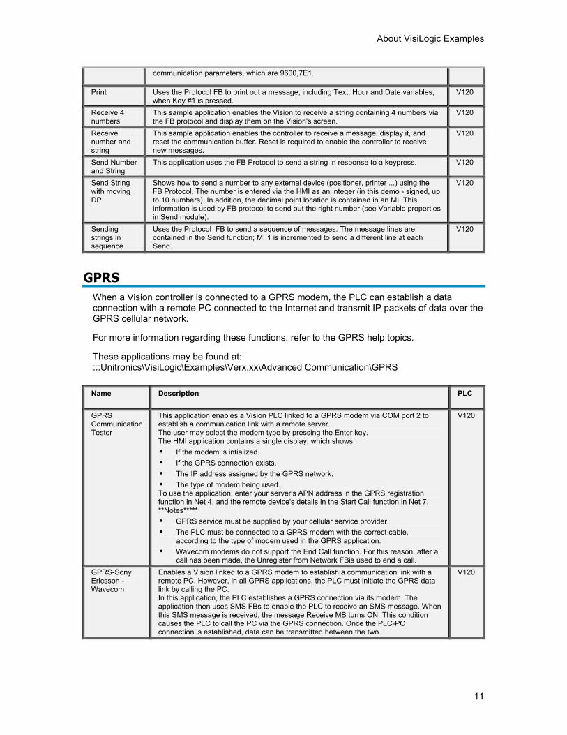
communication parameters, which are 9600,7E1.
Print Uses the Protocol FB to print out a message, including Text, Hour and Date variables, when Key #1 is pressed.
V120
Receive 4 numbers
This sample application enables the Vision to receive a string containing 4 numbers via the FB protocol and display them on the Vision's screen.
V120
Receive number and string
This sample application enables the controller to receive a message, display it, and reset the communication buffer. Reset is required to enable the controller to receive new messages.
V120
Send Number and String
This application uses the FB Protocol to send a string in response to a keypress. V120
Send String with moving DP
Shows how to send a number to any external device (positioner, printer ...) using the FB Protocol. The number is entered via the HMI as an integer (in this demo - signed, up to 10 numbers). In addition, the decimal point location is contained in an MI. This information is used by FB protocol to send out the right number (see Variable properties in Send module).
V120
Sending strings in sequence
Uses the Protocol FB to send a sequence of messages. The message lines are contained in the Send function; MI 1 is incremented to send a different line at each Send.
V120
GPRS
When a Vision controller is connected to a GPRS modem, the PLC can establish a data connection with a remote PC connected to the Internet and transmit IP packets of data over the GPRS cellular network.
For more information regarding these functions, refer to the GPRS help topics.
These applications may be found at: :::Unitronics\VisiLogic\Examples\Verx.xx\Advanced Communication\GPRS
Name Description PLC
GPRS Communication Tester
This application enables a Vision PLC linked to a GPRS modem via COM port 2 to establish a communication link with a remote server. The user may select the modem type by pressing the Enter key. The HMI application contains a single display, which shows: • If the modem is intialized. • If the GPRS connection exists. • The IP address assigned by the GPRS network. • The type of modem being used. To use the application, enter your server's APN address in the GPRS registration function in Net 4, and the remote device's details in the Start Call function in Net 7. **Notes***** • GPRS service must be supplied by your cellular service provider. • The PLC must be connected to a GPRS modem with the correct cable,
according to the type of modem used in the GPRS application. • Wavecom modems do not support the End Call function. For this reason, after a
call has been made, the Unregister from Network FBis used to end a call.
V120
GPRS-Sony Ericsson - Wavecom
Enables a Vision linked to a GPRS modem to establish a communication link with a remote PC. However, in all GPRS applications, the PLC must initiate the GPRS data link by calling the PC. In this application, the PLC establishes a GPRS connection via its modem. The application then uses SMS FBs to enable the PLC to receive an SMS message. When this SMS message is received, the message Receive MB turns ON. This condition causes the PLC to call the PC via the GPRS connection. Once the PLC-PC connection is established, data can be transmitted between the two.
V120
VisiLogic Examples
12
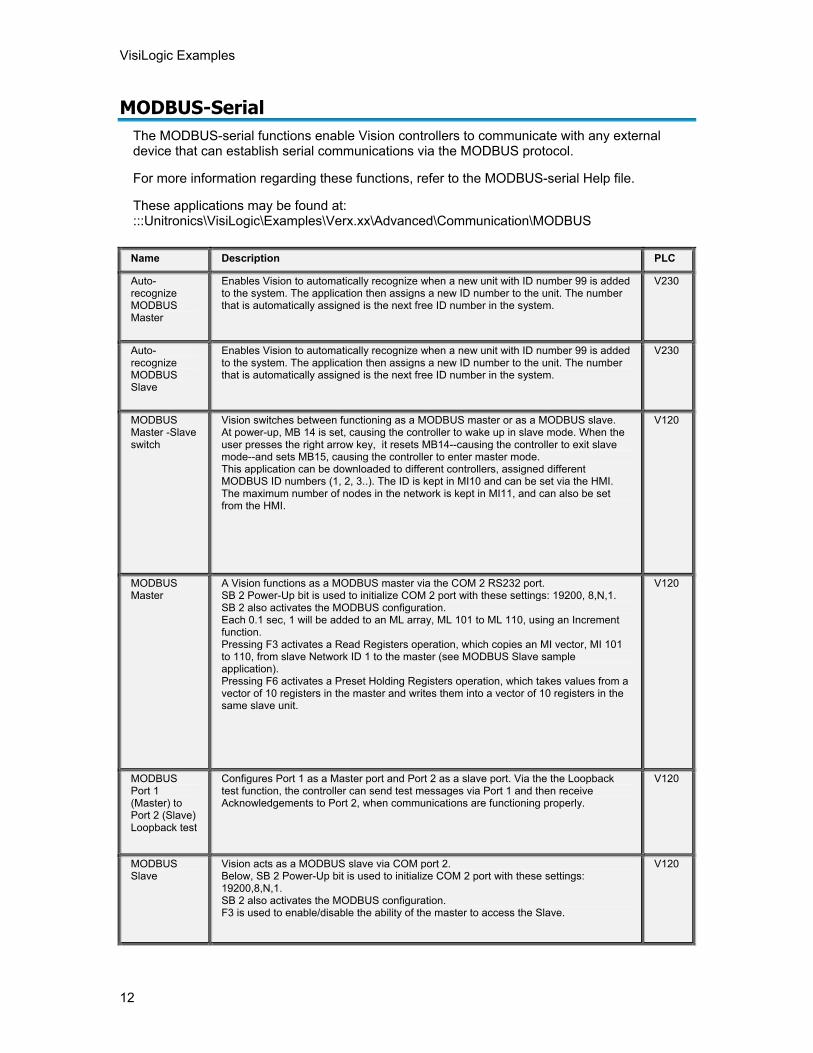
MODBUS-Serial The MODBUS-serial functions enable Vision controllers to communicate with any external device that can establish serial communications via the MODBUS protocol.
For more information regarding these functions, refer to the MODBUS-serial Help file.
These applications may be found at: :::Unitronics\VisiLogic\Examples\Verx.xx\Advanced\Communication\MODBUS
Name Description PLC
Auto-recognize MODBUS Master
Enables Vision to automatically recognize when a new unit with ID number 99 is added to the system. The application then assigns a new ID number to the unit. The number that is automatically assigned is the next free ID number in the system.
V230
Auto- recognize MODBUS Slave
Enables Vision to automatically recognize when a new unit with ID number 99 is added to the system. The application then assigns a new ID number to the unit. The number that is automatically assigned is the next free ID number in the system.
V230
MODBUS Master -Slave switch
Vision switches between functioning as a MODBUS master or as a MODBUS slave. At power-up, MB 14 is set, causing the controller to wake up in slave mode. When the user presses the right arrow key, it resets MB14--causing the controller to exit slave mode--and sets MB15, causing the controller to enter master mode. This application can be downloaded to different controllers, assigned different MODBUS ID numbers (1, 2, 3..). The ID is kept in MI10 and can be set via the HMI. The maximum number of nodes in the network is kept in MI11, and can also be set from the HMI.
V120
MODBUS Master
A Vision functions as a MODBUS master via the COM 2 RS232 port. SB 2 Power-Up bit is used to initialize COM 2 port with these settings: 19200, 8,N,1. SB 2 also activates the MODBUS configuration. Each 0.1 sec, 1 will be added to an ML array, ML 101 to ML 110, using an Increment function. Pressing F3 activates a Read Registers operation, which copies an MI vector, MI 101 to 110, from slave Network ID 1 to the master (see MODBUS Slave sample application). Pressing F6 activates a Preset Holding Registers operation, which takes values from a vector of 10 registers in the master and writes them into a vector of 10 registers in the same slave unit.
V120
MODBUS Port 1 (Master) to Port 2 (Slave) Loopback test
Configures Port 1 as a Master port and Port 2 as a slave port. Via the the Loopback test function, the controller can send test messages via Port 1 and then receive Acknowledgements to Port 2, when communications are functioning properly.
V120
MODBUS Slave
Vision acts as a MODBUS slave via COM port 2. Below, SB 2 Power-Up bit is used to initialize COM 2 port with these settings: 19200,8,N,1. SB 2 also activates the MODBUS configuration. F3 is used to enable/disable the ability of the master to access the Slave.
V120
About VisiLogic Examples
13
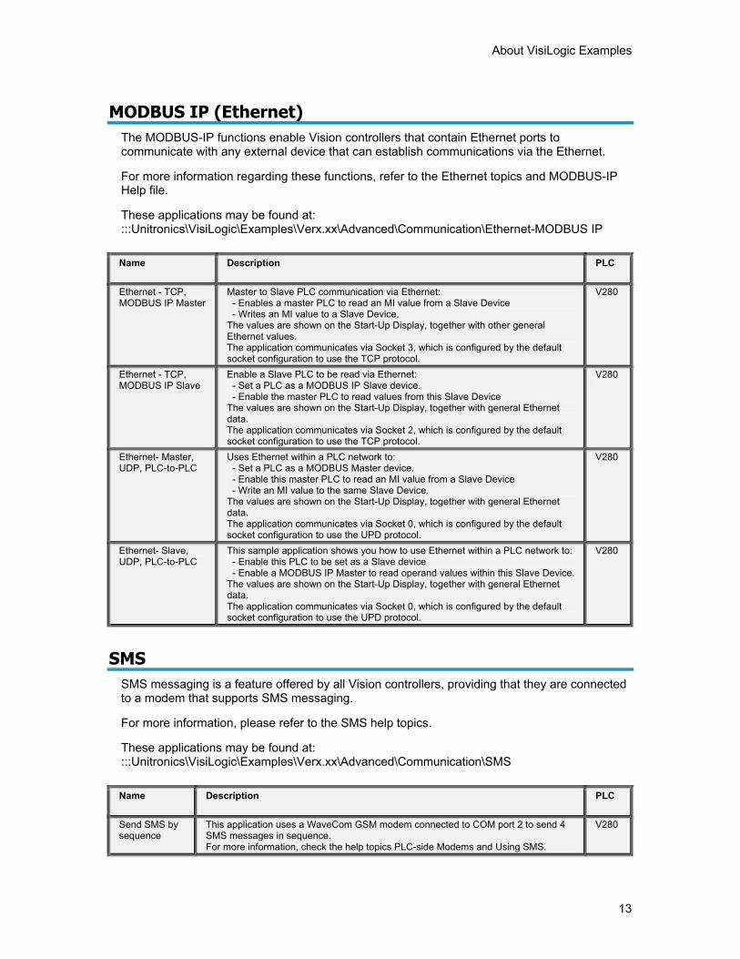
MODBUS IP (Ethernet)
The MODBUS-IP functions enable Vision controllers that contain Ethernet ports to communicate with any external device that can establish communications via the Ethernet.
For more information regarding these functions, refer to the Ethernet topics and MODBUS-IP Help file.
These applications may be found at: :::Unitronics\VisiLogic\Examples\Verx.xx\Advanced\Communication\Ethernet-MODBUS IP
Name Description PLC
Ethernet - TCP, MODBUS IP Master
Master to Slave PLC communication via Ethernet: - Enables a master PLC to read an MI value from a Slave Device - Writes an MI value to a Slave Device. The values are shown on the Start-Up Display, together with other general Ethernet values. The application communicates via Socket 3, which is configured by the default socket configuration to use the TCP protocol.
V280
Ethernet - TCP, MODBUS IP Slave
Enable a Slave PLC to be read via Ethernet: - Set a PLC as a MODBUS IP Slave device. - Enable the master PLC to read values from this Slave Device The values are shown on the Start-Up Display, together with general Ethernet data. The application communicates via Socket 2, which is configured by the default socket configuration to use the TCP protocol.
V280
Ethernet- Master, UDP, PLC-to-PLC
Uses Ethernet within a PLC network to: - Set a PLC as a MODBUS Master device. - Enable this master PLC to read an MI value from a Slave Device - Write an MI value to the same Slave Device. The values are shown on the Start-Up Display, together with general Ethernet data. The application communicates via Socket 0, which is configured by the default socket configuration to use the UPD protocol.
V280
Ethernet- Slave, UDP, PLC-to-PLC
This sample application shows you how to use Ethernet within a PLC network to: - Enable this PLC to be set as a Slave device - Enable a MODBUS IP Master to read operand values within this Slave Device. The values are shown on the Start-Up Display, together with general Ethernet data. The application communicates via Socket 0, which is configured by the default socket configuration to use the UPD protocol.
V280
SMS
SMS messaging is a feature offered by all Vision controllers, providing that they are connected to a modem that supports SMS messaging.
For more information, please refer to the SMS help topics.
These applications may be found at: :::Unitronics\VisiLogic\Examples\Verx.xx\Advanced\Communication\SMS
Name Description PLC
Send SMS by sequence
This application uses a WaveCom GSM modem connected to COM port 2 to send 4 SMS messages in sequence. For more information, check the help topics PLC-side Modems and Using SMS.
V280
VisiLogic Examples
14
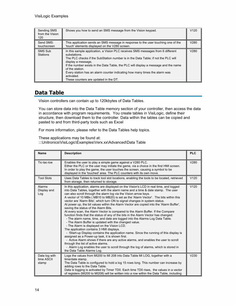
Sending SMS from the Vision 120
Shows you how to send an SMS message from the Vision keypad. V120
Send SMS: touchscreen
This application sends an SMS message in response to the user touching one of the 'touch' elements displayed on the V280 screen.
V280
SMS Sub Stations
In this sample application, a Vision PLC receives SMS messages from 6 different substations. The PLC checks if the SubStation number is in the Data Table; if not the PLC will display a message, If the number exists in the Data Table, the PLC will display a message and the name of the station. Every station has an alarm counter indicating how many times the alarm was activated. These counters are updated in the DT.
V280
Data Table
Vision controllers can contain up to 120kbytes of Data Tables.
You can store data into the Data Table memory section of your controller, then access the data in accordance with program requirements. You create tables in VisiLogic, define their structure, then download them to the controller. Data within the tables can be copied and pasted to and from third-party tools such as Excel
For more information, please refer to the Data Tables help topics.
These applications may be found at: :::Unitronics\VisiLogic\Examples\Verx.xx\Advanced\Data Table
Name Description PLC
Tic-tac-toe Enables the user to play a simple game against a V280 PLC. Either the PLC or the user may initiate the game, via a choice in the first HMI screen. In order to play the game, the user touches the screen, causing a symbol to be displayed in the 'touched' area. The PLC counters with its own move.
V280
Tool Slots Uses Data Tables to track tool slot locations, enabling the tools to be located, retrieved from storage, then returned to storage.
V120
Alarms Display and Log
In this application, alarms are displayed on the Vision's LCD in real time, and logged into Data Tables, together with the alarm name and a time & date stamp. The user can also scroll through the alarm log via the Vision arrow keys. A vector of 10 MBs ( MB10 to MB20) is set as the 'Alarm Vector'. The bits within this vector are 'Alarm Bits', which turn ON to signal changes in system status. At power up, the bit values within the Alarm Vector are copied into the 'Alarm Buffer', saving the status of the Alarm Bits. At every scan, the Alarm Vector is compared to the Alarm Buffer. If the Compare function finds that the status of any of the bits in the Alarm Vector has changed: - The alarm name, time, and date are logged into the Alarms Log Data Table. - The Alarm Buffer is updated with the changed value. - The Alarm is displayed on the Vision LCD. The application contains 3 HMI displays. - !Start-up Display contains the application name. Since the running of this display is assigned as a Power-up task, it is shown first. - Active Alarm shows if there are any active alarms, and enables the user to scroll through the list of active alarms. - Alarm Log enables the user to scroll through the log of alarms, which is stored in the Data Table Alarms Log.
V120
Data log with time ASCII stamp
Logs the values from MI200 to MI 208 into Data Table MI LOG, together with a time/date stamp. The Data Table is configured to hold a log 15 rows long. This number can increase by adding rows to the Data Table. Data is logging is activated by Timer TD0. Each time TD0 rises, the values in a vector of registers (MI200 to MI208) will be written into a row within the Data Table, including
V230
About VisiLogic Examples
15
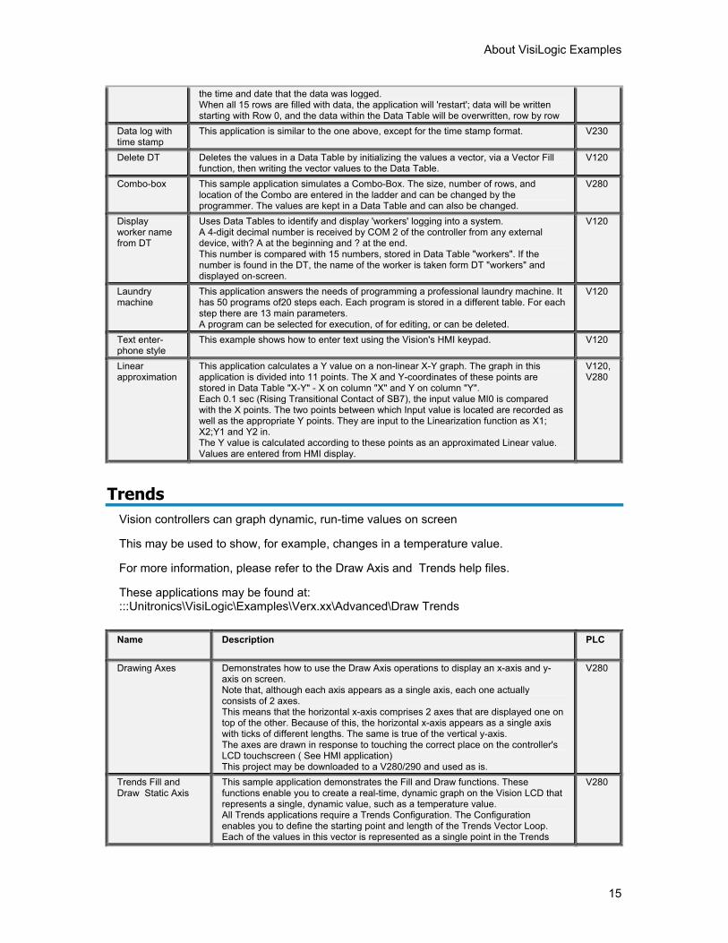
the time and date that the data was logged. When all 15 rows are filled with data, the application will 'restart'; data will be written starting with Row 0, and the data within the Data Table will be overwritten, row by row
Data log with time stamp
This application is similar to the one above, except for the time stamp format. V230
Delete DT Deletes the values in a Data Table by initializing the values a vector, via a Vector Fill function, then writing the vector values to the Data Table.
V120
Combo-box This sample application simulates a Combo-Box. The size, number of rows, and location of the Combo are entered in the ladder and can be changed by the programmer. The values are kept in a Data Table and can also be changed.
V280
Display worker name from DT
Uses Data Tables to identify and display 'workers' logging into a system. A 4-digit decimal number is received by COM 2 of the controller from any external device, with? A at the beginning and ? at the end. This number is compared with 15 numbers, stored in Data Table "workers". If the number is found in the DT, the name of the worker is taken form DT "workers" and displayed on-screen.
V120
Laundry machine
This application answers the needs of programming a professional laundry machine. It has 50 programs of20 steps each. Each program is stored in a different table. For each step there are 13 main parameters. A program can be selected for execution, of for editing, or can be deleted.
V120
Text enter-phone style
This example shows how to enter text using the Vision's HMI keypad. V120
Linear approximation
This application calculates a Y value on a non-linear X-Y graph. The graph in this application is divided into 11 points. The X and Y-coordinates of these points are stored in Data Table "X-Y" - X on column "X" and Y on column "Y". Each 0.1 sec (Rising Transitional Contact of SB7), the input value MI0 is compared with the X points. The two points between which Input value is located are recorded as well as the appropriate Y points. They are input to the Linearization function as X1; X2;Y1 and Y2 in. The Y value is calculated according to these points as an approximated Linear value. Values are entered from HMI display.
V120, V280
Trends
Vision controllers can graph dynamic, run-time values on screen
This may be used to show, for example, changes in a temperature value.
For more information, please refer to the Draw Axis and Trends help files.
These applications may be found at: :::Unitronics\VisiLogic\Examples\Verx.xx\Advanced\Draw Trends
Name Description PLC
Drawing Axes Demonstrates how to use the Draw Axis operations to display an x-axis and y-axis on screen. Note that, although each axis appears as a single axis, each one actually consists of 2 axes. This means that the horizontal x-axis comprises 2 axes that are displayed one on top of the other. Because of this, the horizontal x-axis appears as a single axis with ticks of different lengths. The same is true of the vertical y-axis. The axes are drawn in response to touching the correct place on the controller's LCD touchscreen ( See HMI application) This project may be downloaded to a V280/290 and used as is.
V280
Trends Fill and Draw Static Axis
This sample application demonstrates the Fill and Draw functions. These functions enable you to create a real-time, dynamic graph on the Vision LCD that represents a single, dynamic value, such as a temperature value. All Trends applications require a Trends Configuration. The Configuration enables you to define the starting point and length of the Trends Vector Loop. Each of the values in this vector is represented as a single point in the Trends
V280
VisiLogic Examples
16
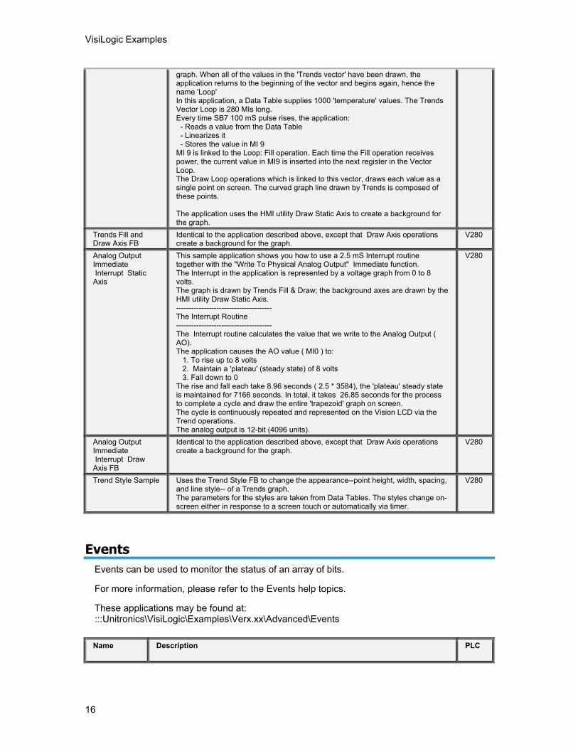
graph. When all of the values in the 'Trends vector' have been drawn, the application returns to the beginning of the vector and begins again, hence the name 'Loop' In this application, a Data Table supplies 1000 'temperature' values. The Trends Vector Loop is 280 MIs long. Every time SB7 100 mS pulse rises, the application: - Reads a value from the Data Table - Linearizes it - Stores the value in MI 9 MI 9 is linked to the Loop: Fill operation. Each time the Fill operation receives power, the current value in MI9 is inserted into the next register in the Vector Loop. The Draw Loop operations which is linked to this vector, draws each value as a single point on screen. The curved graph line drawn by Trends is composed of these points. The application uses the HMI utility Draw Static Axis to create a background for the graph.
Trends Fill and Draw Axis FB
Identical to the application described above, except that Draw Axis operations create a background for the graph.
V280
Analog Output Immediate Interrupt Static Axis
This sample application shows you how to use a 2.5 mS Interrupt routine together with the "Write To Physical Analog Output" Immediate function. The Interrupt in the application is represented by a voltage graph from 0 to 8 volts. The graph is drawn by Trends Fill & Draw; the background axes are drawn by the HMI utility Draw Static Axis. -------------------------------------- The Interrupt Routine -------------------------------------- The Interrupt routine calculates the value that we write to the Analog Output ( AO). The application causes the AO value ( MI0 ) to: 1. To rise up to 8 volts 2. Maintain a 'plateau' (steady state) of 8 volts 3. Fall down to 0 The rise and fall each take 8.96 seconds ( 2.5 * 3584), the 'plateau' steady state is maintained for 7166 seconds. In total, it takes 26.85 seconds for the process to complete a cycle and draw the entire 'trapezoid' graph on screen. The cycle is continuously repeated and represented on the Vision LCD via the Trend operations. The analog output is 12-bit (4096 units).
V280
Analog Output Immediate Interrupt Draw Axis FB
Identical to the application described above, except that Draw Axis operations create a background for the graph.
V280
Trend Style Sample Uses the Trend Style FB to change the appearance--point height, width, spacing, and line style-- of a Trends graph. The parameters for the styles are taken from Data Tables. The styles change on-screen either in response to a screen touch or automatically via timer.
V280
Events
Events can be used to monitor the status of an array of bits.
For more information, please refer to the Events help topics.
These applications may be found at: :::Unitronics\VisiLogic\Examples\Verx.xx\Advanced\Events
Name Description PLC
About VisiLogic Examples
17
Alarms Display and Log
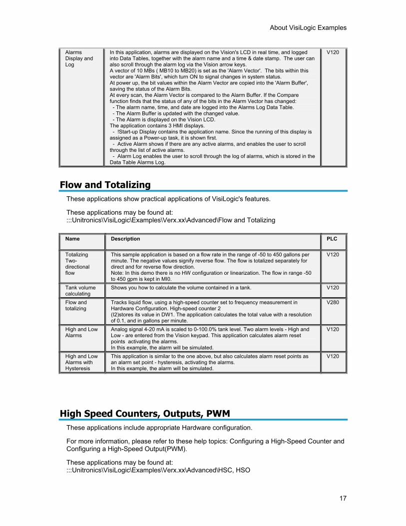
In this application, alarms are displayed on the Vision's LCD in real time, and logged into Data Tables, together with the alarm name and a time & date stamp. The user can also scroll through the alarm log via the Vision arrow keys. A vector of 10 MBs ( MB10 to MB20) is set as the 'Alarm Vector'. The bits within this vector are 'Alarm Bits', which turn ON to signal changes in system status. At power up, the bit values within the Alarm Vector are copied into the 'Alarm Buffer', saving the status of the Alarm Bits. At every scan, the Alarm Vector is compared to the Alarm Buffer. If the Compare function finds that the status of any of the bits in the Alarm Vector has changed: - The alarm name, time, and date are logged into the Alarms Log Data Table. - The Alarm Buffer is updated with the changed value. - The Alarm is displayed on the Vision LCD. The application contains 3 HMI displays. - !Start-up Display contains the application name. Since the running of this display is assigned as a Power-up task, it is shown first. - Active Alarm shows if there are any active alarms, and enables the user to scroll through the list of active alarms. - Alarm Log enables the user to scroll through the log of alarms, which is stored in the Data Table Alarms Log.
V120
Flow and Totalizing
These applications show practical applications of VisiLogic's features.
These applications may be found at: :::Unitronics\VisiLogic\Examples\Verx.xx\Advanced\Flow and Totalizing
Name Description PLC
Totalizing Two-directional flow
This sample application is based on a flow rate in the range of -50 to 450 gallons per minute. The negative values signify reverse flow. The flow is totalized separately for direct and for reverse flow direction. Note: In this demo there is no HW configuration or linearization. The flow in range -50 to 450 gpm is kept in MI0.
V120
Tank volume calculating
Shows you how to calculate the volume contained in a tank. V120
Flow and totalizing
Tracks liquid flow, using a high-speed counter set to frequency measurement in Hardware Configuration. High-speed counter 2 (I2)stores its value in DW1. The application calculates the total value with a resolution of 0.1, and in gallons per minute.
V280
High and Low Alarms
Analog signal 4-20 mA is scaled to 0-100.0% tank level. Two alarm levels - High and Low - are entered from the Vision keypad. This application calculates alarm reset points activating the alarms. In this example, the alarm will be simulated.
V120
High and Low Alarms with Hysteresis
This application is similar to the one above, but also calculates alarm reset points as an alarm set point - hysteresis, activating the alarms. In this example, the alarm will be simulated.
V120
High Speed Counters, Outputs, PWM These applications include appropriate Hardware configuration.
For more information, please refer to these help topics: Configuring a High-Speed Counter and Configuring a High-Speed Output(PWM).
These applications may be found at: :::Unitronics\VisiLogic\Examples\Verx.xx\Advanced\HSC, HSO
VisiLogic Examples
18
Name Description PLC
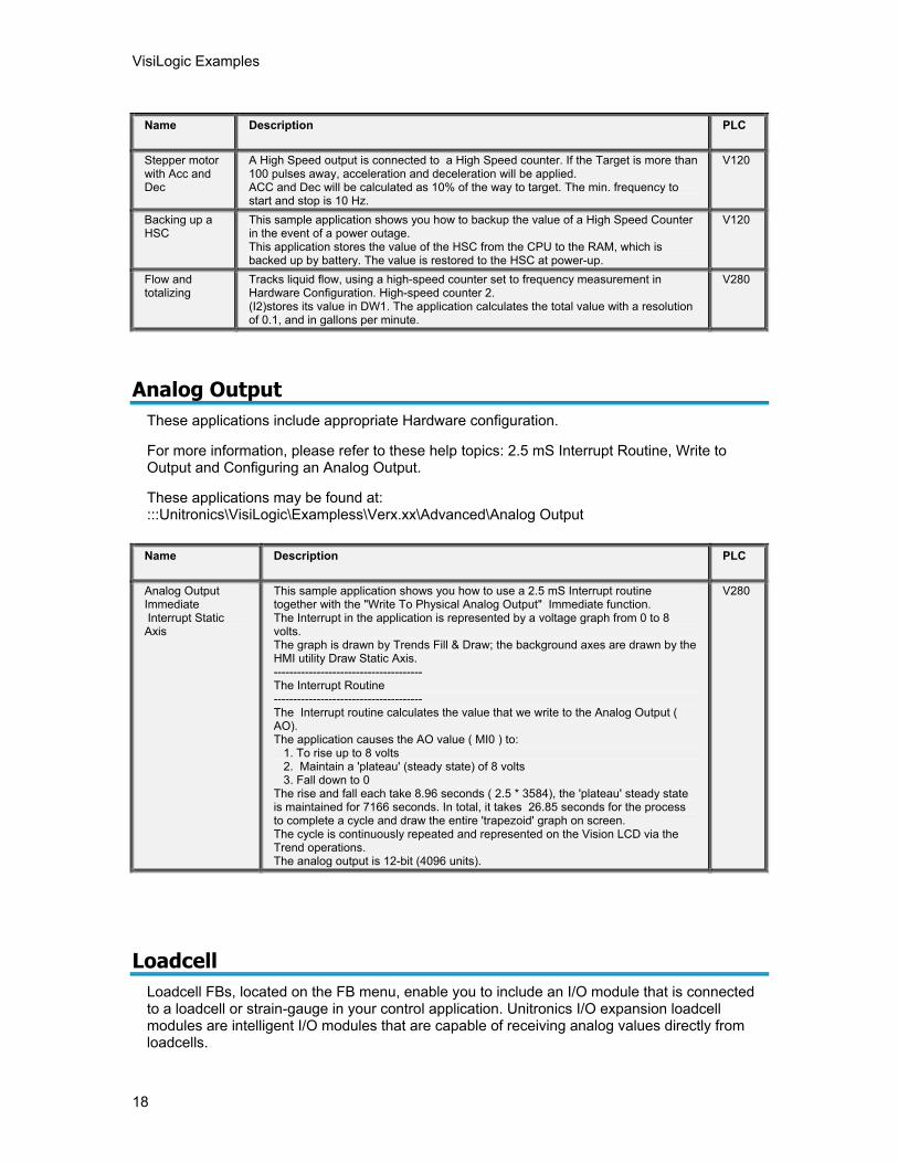
Stepper motor with Acc and Dec
A High Speed output is connected to a High Speed counter. If the Target is more than 100 pulses away, acceleration and deceleration will be applied. ACC and Dec will be calculated as 10% of the way to target. The min. frequency to start and stop is 10 Hz.
V120
Backing up a HSC
This sample application shows you how to backup the value of a High Speed Counter in the event of a power outage. This application stores the value of the HSC from the CPU to the RAM, which is backed up by battery. The value is restored to the HSC at power-up.
V120
Flow and totalizing
Tracks liquid flow, using a high-speed counter set to frequency measurement in Hardware Configuration. High-speed counter 2. (I2)stores its value in DW1. The application calculates the total value with a resolution of 0.1, and in gallons per minute.
V280
Analog Output These applications include appropriate Hardware configuration.
For more information, please refer to these help topics: 2.5 mS Interrupt Routine, Write to Output and Configuring an Analog Output.
These applications may be found at: :::Unitronics\VisiLogic\Exampless\Verx.xx\Advanced\Analog Output
Name Description PLC
Analog Output Immediate Interrupt Static Axis
This sample application shows you how to use a 2.5 mS Interrupt routine together with the "Write To Physical Analog Output" Immediate function. The Interrupt in the application is represented by a voltage graph from 0 to 8 volts. The graph is drawn by Trends Fill & Draw; the background axes are drawn by the HMI utility Draw Static Axis. -------------------------------------- The Interrupt Routine -------------------------------------- The Interrupt routine calculates the value that we write to the Analog Output ( AO). The application causes the AO value ( MI0 ) to: 1. To rise up to 8 volts 2. Maintain a 'plateau' (steady state) of 8 volts 3. Fall down to 0 The rise and fall each take 8.96 seconds ( 2.5 * 3584), the 'plateau' steady state is maintained for 7166 seconds. In total, it takes 26.85 seconds for the process to complete a cycle and draw the entire 'trapezoid' graph on screen. The cycle is continuously repeated and represented on the Vision LCD via the Trend operations. The analog output is 12-bit (4096 units).
V280
Loadcell Loadcell FBs, located on the FB menu, enable you to include an I/O module that is connected to a loadcell or strain-gauge in your control application. Unitronics I/O expansion loadcell modules are intelligent I/O modules that are capable of receiving analog values directly from loadcells.
About VisiLogic Examples
19
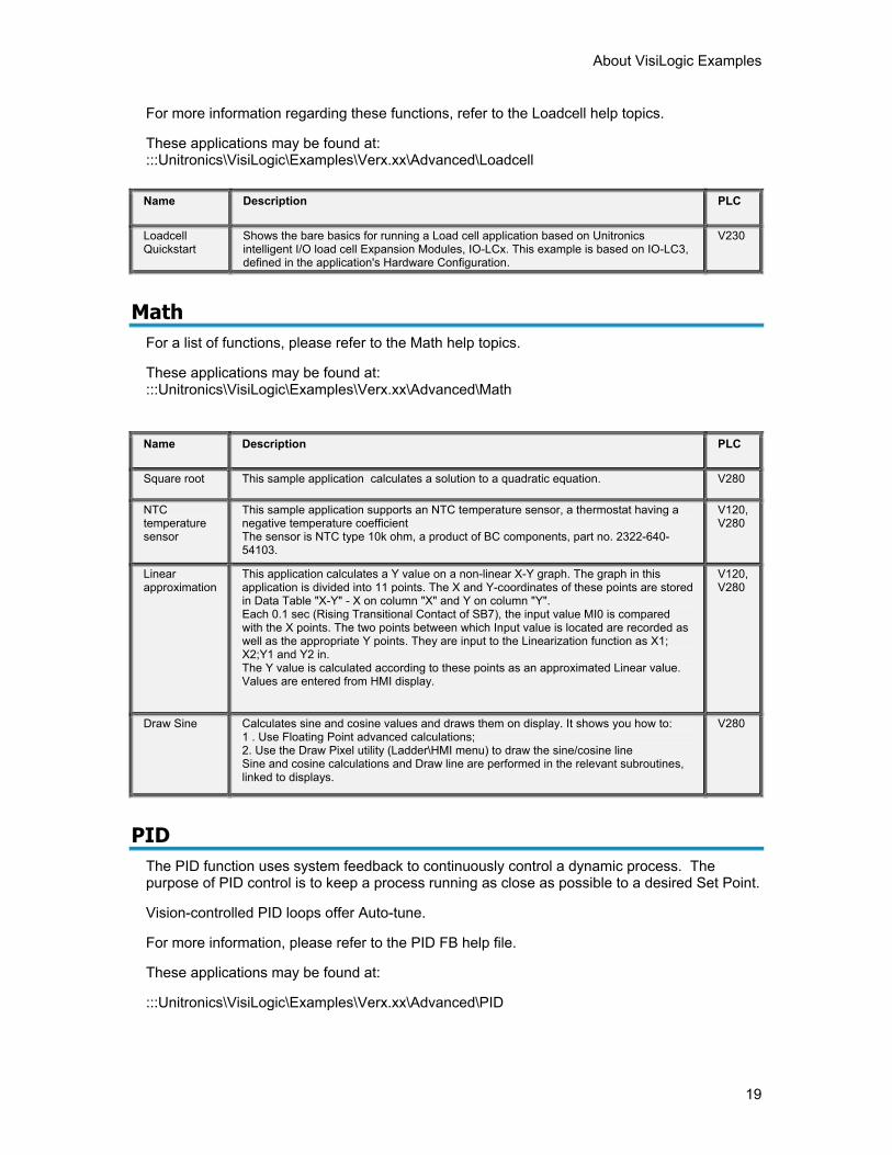
For more information regarding these functions, refer to the Loadcell help topics.
These applications may be found at: :::Unitronics\VisiLogic\Examples\Verx.xx\Advanced\Loadcell
Name Description PLC
Loadcell Quickstart
Shows the bare basics for running a Load cell application based on Unitronics intelligent I/O load cell Expansion Modules, IO-LCx. This example is based on IO-LC3, defined in the application's Hardware Configuration.
V230
Math
For a list of functions, please refer to the Math help topics.
These applications may be found at: :::Unitronics\VisiLogic\Examples\Verx.xx\Advanced\Math
Name Description PLC
Square root This sample application calculates a solution to a quadratic equation. V280
NTC temperature sensor
This sample application supports an NTC temperature sensor, a thermostat having a negative temperature coefficient The sensor is NTC type 10k ohm, a product of BC components, part no. 2322-640-54103.
V120, V280
Linear approximation
This application calculates a Y value on a non-linear X-Y graph. The graph in this application is divided into 11 points. The X and Y-coordinates of these points are stored in Data Table "X-Y" - X on column "X" and Y on column "Y". Each 0.1 sec (Rising Transitional Contact of SB7), the input value MI0 is compared with the X points. The two points between which Input value is located are recorded as well as the appropriate Y points. They are input to the Linearization function as X1; X2;Y1 and Y2 in. The Y value is calculated according to these points as an approximated Linear value. Values are entered from HMI display.
V120, V280
Draw Sine Calculates sine and cosine values and draws them on display. It shows you how to: 1 . Use Floating Point advanced calculations; 2. Use the Draw Pixel utility (Ladder\HMI menu) to draw the sine/cosine line Sine and cosine calculations and Draw line are performed in the relevant subroutines, linked to displays.
V280
PID
The PID function uses system feedback to continuously control a dynamic process. The purpose of PID control is to keep a process running as close as possible to a desired Set Point.
Vision-controlled PID loops offer Auto-tune.
For more information, please refer to the PID FB help file.
These applications may be found at:
:::Unitronics\VisiLogic\Examples\Verx.xx\Advanced\PID
VisiLogic Examples
20
Name Description PLC
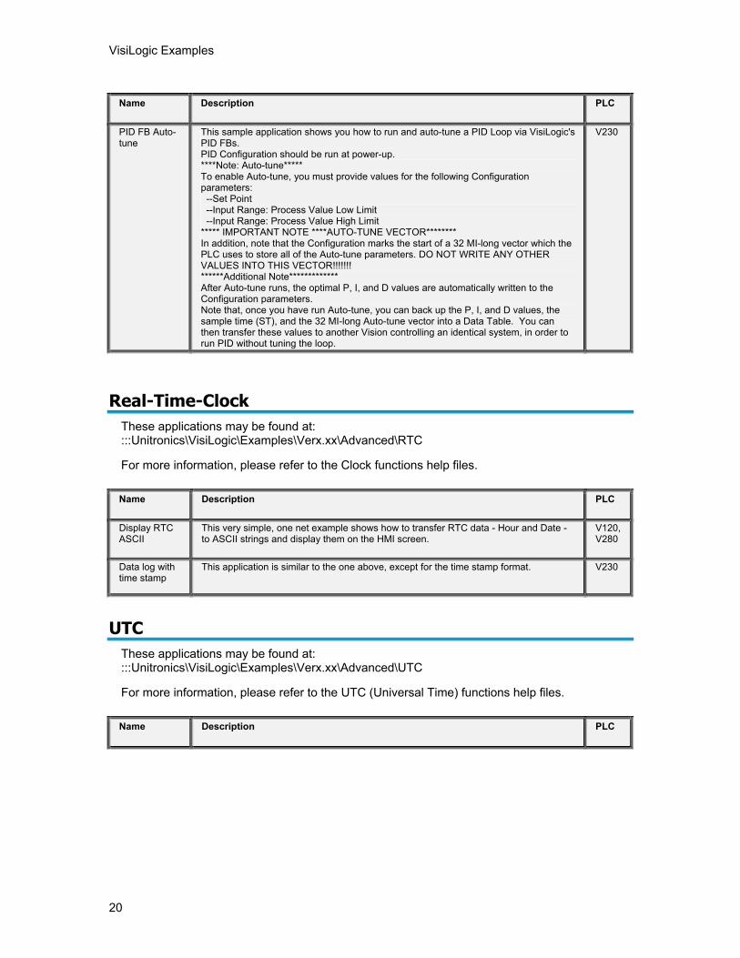
PID FB Auto-tune
This sample application shows you how to run and auto-tune a PID Loop via VisiLogic's PID FBs. PID Configuration should be run at power-up. ****Note: Auto-tune***** To enable Auto-tune, you must provide values for the following Configuration parameters: --Set Point --Input Range: Process Value Low Limit --Input Range: Process Value High Limit ***** IMPORTANT NOTE ****AUTO-TUNE VECTOR******** In addition, note that the Configuration marks the start of a 32 MI-long vector which the PLC uses to store all of the Auto-tune parameters. DO NOT WRITE ANY OTHER VALUES INTO THIS VECTOR!!!!!!! ******Additional Note************* After Auto-tune runs, the optimal P, I, and D values are automatically written to the Configuration parameters. Note that, once you have run Auto-tune, you can back up the P, I, and D values, the sample time (ST), and the 32 MI-long Auto-tune vector into a Data Table. You can then transfer these values to another Vision controlling an identical system, in order to run PID without tuning the loop.
V230
Real-Time-Clock These applications may be found at: :::Unitronics\VisiLogic\Examples\Verx.xx\Advanced\RTC
For more information, please refer to the Clock functions help files.
Name Description PLC
Display RTC ASCII
This very simple, one net example shows how to transfer RTC data - Hour and Date - to ASCII strings and display them on the HMI screen.
V120, V280
Data log with time stamp
This application is similar to the one above, except for the time stamp format. V230
UTC
These applications may be found at: :::Unitronics\VisiLogic\Examples\Verx.xx\Advanced\UTC
For more information, please refer to the UTC (Universal Time) functions help files.
Name Description PLC
About VisiLogic Examples
21
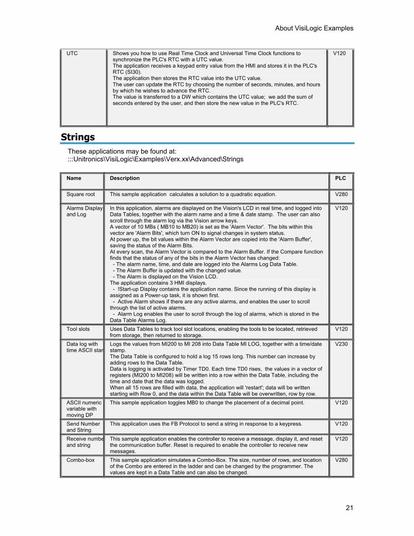
UTC
Shows you how to use Real Time Clock and Universal Time Clock functions to synchronize the PLC's RTC with a UTC value. The application receives a keypad entry value from the HMI and stores it in the PLC's RTC (SI30). The application then stores the RTC value into the UTC value. The user can update the RTC by choosing the number of seconds, minutes, and hours by which he wishes to advance the RTC. The value is transferred to a DW which contains the UTC value; we add the sum of seconds entered by the user, and then store the new value in the PLC's RTC.
V120
Strings These applications may be found at: :::Unitronics\VisiLogic\Examples\Verx.xx\Advanced\Strings
Name Description PLC
Square root This sample application calculates a solution to a quadratic equation. V280
Alarms Display and Log
In this application, alarms are displayed on the Vision's LCD in real time, and logged into Data Tables, together with the alarm name and a time & date stamp. The user can also scroll through the alarm log via the Vision arrow keys. A vector of 10 MBs ( MB10 to MB20) is set as the 'Alarm Vector'. The bits within this vector are 'Alarm Bits', which turn ON to signal changes in system status. At power up, the bit values within the Alarm Vector are copied into the 'Alarm Buffer', saving the status of the Alarm Bits. At every scan, the Alarm Vector is compared to the Alarm Buffer. If the Compare function finds that the status of any of the bits in the Alarm Vector has changed: - The alarm name, time, and date are logged into the Alarms Log Data Table. - The Alarm Buffer is updated with the changed value. - The Alarm is displayed on the Vision LCD. The application contains 3 HMI displays. - !Start-up Display contains the application name. Since the running of this display is assigned as a Power-up task, it is shown first. - Active Alarm shows if there are any active alarms, and enables the user to scroll through the list of active alarms. - Alarm Log enables the user to scroll through the log of alarms, which is stored in the Data Table Alarms Log.
V120
Tool slots Uses Data Tables to track tool slot locations, enabling the tools to be located, retrieved from storage, then returned to storage.
V120
Data log with time ASCII stam
Logs the values from MI200 to MI 208 into Data Table MI LOG, together with a time/date stamp. The Data Table is configured to hold a log 15 rows long. This number can increase by adding rows to the Data Table. Data is logging is activated by Timer TD0. Each time TD0 rises, the values in a vector of registers (MI200 to MI208) will be written into a row within the Data Table, including the time and date that the data was logged. When all 15 rows are filled with data, the application will 'restart'; data will be written starting with Row 0, and the data within the Data Table will be overwritten, row by row.
V230
ASCII numeric variable with moving DP
This sample application toggles MB0 to change the placement of a decimal point. V120
Send Number and String
This application uses the FB Protocol to send a string in response to a keypress. V120
Receive numbeand string
This sample application enables the controller to receive a message, display it, and reset the communication buffer. Reset is required to enable the controller to receive new messages.
V120
Combo-box This sample application simulates a Combo-Box. The size, number of rows, and location of the Combo are entered in the ladder and can be changed by the programmer. The values are kept in a Data Table and can also be changed.
V280
VisiLogic Examples
22
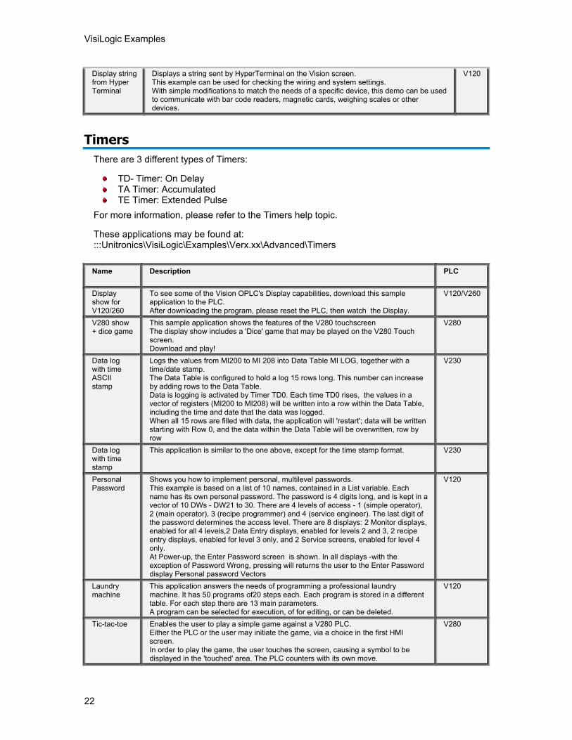
Display string from Hyper Terminal
Displays a string sent by HyperTerminal on the Vision screen. This example can be used for checking the wiring and system settings. With simple modifications to match the needs of a specific device, this demo can be used to communicate with bar code readers, magnetic cards, weighing scales or other devices.
V120
Timers
There are 3 different types of Timers:
TD- Timer: On Delay TA Timer: Accumulated TE Timer: Extended Pulse
For more information, please refer to the Timers help topic.
These applications may be found at: :::Unitronics\VisiLogic\Examples\Verx.xx\Advanced\Timers
Name Description PLC
Display show for V120/260
To see some of the Vision OPLC's Display capabilities, download this sample application to the PLC. After downloading the program, please reset the PLC, then watch the Display.
V120/V260
V280 show + dice game
This sample application shows the features of the V280 touchscreen The display show includes a 'Dice' game that may be played on the V280 Touch screen. Download and play!
V280
Data log with time ASCII stamp
Logs the values from MI200 to MI 208 into Data Table MI LOG, together with a time/date stamp. The Data Table is configured to hold a log 15 rows long. This number can increase by adding rows to the Data Table. Data is logging is activated by Timer TD0. Each time TD0 rises, the values in a vector of registers (MI200 to MI208) will be written into a row within the Data Table, including the time and date that the data was logged. When all 15 rows are filled with data, the application will 'restart'; data will be written starting with Row 0, and the data within the Data Table will be overwritten, row by row
V230
Data log with time stamp
This application is similar to the one above, except for the time stamp format. V230
Personal Password
Shows you how to implement personal, multilevel passwords. This example is based on a list of 10 names, contained in a List variable. Each name has its own personal password. The password is 4 digits long, and is kept in a vector of 10 DWs - DW21 to 30. There are 4 levels of access - 1 (simple operator), 2 (main operator), 3 (recipe programmer) and 4 (service engineer). The last digit of the password determines the access level. There are 8 displays: 2 Monitor displays, enabled for all 4 levels,2 Data Entry displays, enabled for levels 2 and 3, 2 recipe entry displays, enabled for level 3 only, and 2 Service screens, enabled for level 4 only. At Power-up, the Enter Password screen is shown. In all displays -with the exception of Password Wrong, pressing will returns the user to the Enter Password display Personal password Vectors
V120
Laundry machine
This application answers the needs of programming a professional laundry machine. It has 50 programs of20 steps each. Each program is stored in a different table. For each step there are 13 main parameters. A program can be selected for execution, of for editing, or can be deleted.
V120
Tic-tac-toe Enables the user to play a simple game against a V280 PLC. Either the PLC or the user may initiate the game, via a choice in the first HMI screen. In order to play the game, the user touches the screen, causing a symbol to be displayed in the 'touched' area. The PLC counters with its own move.
V280
About VisiLogic Examples
23
Interrupt
These applications may be found at: :::Unitronics\VisiLogic\Examples\Verx.xx\Advanced\Interrupts
For more information, please refer to the Help topic 2.5 mS Interrupt Routine
Name Description PLC
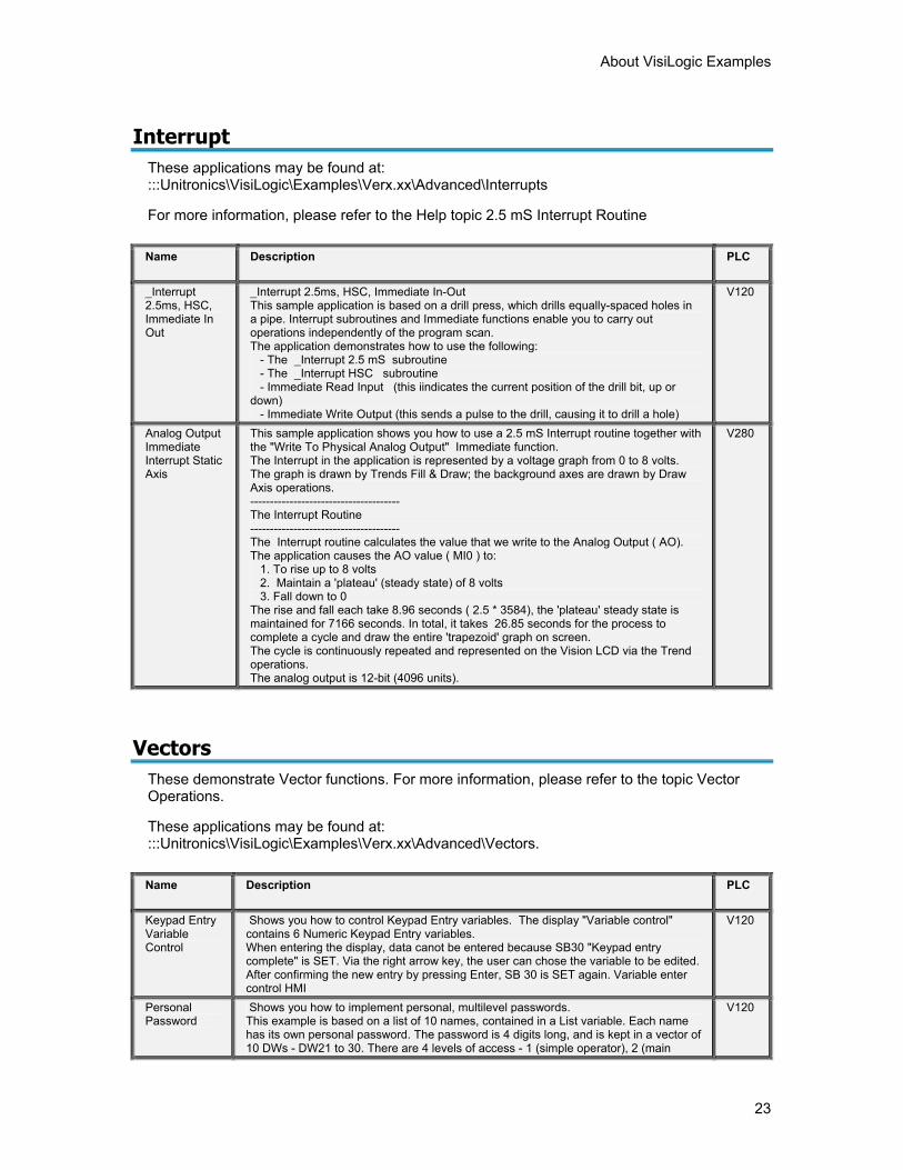
_Interrupt 2.5ms, HSC, Immediate In Out
_Interrupt 2.5ms, HSC, Immediate In-Out This sample application is based on a drill press, which drills equally-spaced holes in a pipe. Interrupt subroutines and Immediate functions enable you to carry out operations independently of the program scan. The application demonstrates how to use the following: - The _Interrupt 2.5 mS subroutine - The _Interrupt HSC subroutine - Immediate Read Input (this iindicates the current position of the drill bit, up or down) - Immediate Write Output (this sends a pulse to the drill, causing it to drill a hole)
V120
Analog Output Immediate Interrupt Static Axis
This sample application shows you how to use a 2.5 mS Interrupt routine together with the "Write To Physical Analog Output" Immediate function. The Interrupt in the application is represented by a voltage graph from 0 to 8 volts. The graph is drawn by Trends Fill & Draw; the background axes are drawn by Draw Axis operations. -------------------------------------- The Interrupt Routine -------------------------------------- The Interrupt routine calculates the value that we write to the Analog Output ( AO). The application causes the AO value ( MI0 ) to: 1. To rise up to 8 volts 2. Maintain a 'plateau' (steady state) of 8 volts 3. Fall down to 0 The rise and fall each take 8.96 seconds ( 2.5 * 3584), the 'plateau' steady state is maintained for 7166 seconds. In total, it takes 26.85 seconds for the process to complete a cycle and draw the entire 'trapezoid' graph on screen. The cycle is continuously repeated and represented on the Vision LCD via the Trend operations. The analog output is 12-bit (4096 units).
V280
Vectors These demonstrate Vector functions. For more information, please refer to the topic Vector Operations.
These applications may be found at: :::Unitronics\VisiLogic\Examples\Verx.xx\Advanced\Vectors.
Name Description PLC
Keypad Entry Variable Control
Shows you how to control Keypad Entry variables. The display "Variable control" contains 6 Numeric Keypad Entry variables. When entering the display, data canot be entered because SB30 "Keypad entry complete" is SET. Via the right arrow key, the user can chose the variable to be edited. After confirming the new entry by pressing Enter, SB 30 is SET again. Variable enter control HMI
V120
Personal Password
Shows you how to implement personal, multilevel passwords. This example is based on a list of 10 names, contained in a List variable. Each name has its own personal password. The password is 4 digits long, and is kept in a vector of 10 DWs - DW21 to 30. There are 4 levels of access - 1 (simple operator), 2 (main
V120
VisiLogic Examples
24
operator), 3 (recipe programmer) and 4 (service engineer). The last digit of the password determines the access level. There are 8 displays: 2 Monitor displays, enabled for all 4 levels,2 Data Entry displays, enabled for levels 2 and 3, 2 recipe entry displays, enabled for level 3 only, and 2 Service screens, enabled for level 4 only. At Power-up, the Enter Password screen is shown. In all displays -with the exception of Password Wrong, pressing will returns the user to the Enter Password display Personal password Vectors
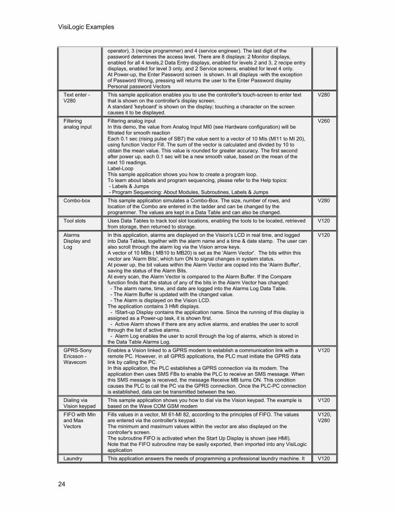
Text enter - V280
This sample application enables you to use the controller's touch-screen to enter text that is shown on the controller's display screen. A standard 'keyboard' is shown on the display; touching a character on the screen causes it to be displayed.
V280
Filtering analog input
Filtering analog input In this demo, the value from Analog Input MI0 (see Hardware configuration) will be filtrated for smooth reaction Each 0.1 sec (rising pulse of SB7) the value sent to a vector of 10 MIs (MI11 to MI 20), using function Vector Fill. The sum of the vector is calculated and divided by 10 to obtain the mean value. This value is rounded for greater accuracy. The first second after power up, each 0.1 sec will be a new smooth value, based on the mean of the next 10 readings. Label-Loop This sample application shows you how to create a program loop. To learn about labels and program sequencing, please refer to the Help topics: - Labels & Jumps - Program Sequencing: About Modules, Subroutines, Labels & Jumps
V260
Combo-box This sample application simulates a Combo-Box. The size, number of rows, and location of the Combo are entered in the ladder and can be changed by the programmer. The values are kept in a Data Table and can also be changed.
V280
Tool slots Uses Data Tables to track tool slot locations, enabling the tools to be located, retrieved from storage, then returned to storage.
V120
Alarms Display and Log
In this application, alarms are displayed on the Vision's LCD in real time, and logged into Data Tables, together with the alarm name and a time & date stamp. The user can also scroll through the alarm log via the Vision arrow keys. A vector of 10 MBs ( MB10 to MB20) is set as the 'Alarm Vector'. The bits within this vector are 'Alarm Bits', which turn ON to signal changes in system status. At power up, the bit values within the Alarm Vector are copied into the 'Alarm Buffer', saving the status of the Alarm Bits. At every scan, the Alarm Vector is compared to the Alarm Buffer. If the Compare function finds that the status of any of the bits in the Alarm Vector has changed: - The alarm name, time, and date are logged into the Alarms Log Data Table. - The Alarm Buffer is updated with the changed value. - The Alarm is displayed on the Vision LCD. The application contains 3 HMI displays. - !Start-up Display contains the application name. Since the running of this display is assigned as a Power-up task, it is shown first. - Active Alarm shows if there are any active alarms, and enables the user to scroll through the list of active alarms. - Alarm Log enables the user to scroll through the log of alarms, which is stored in the Data Table Alarms Log.
V120
GPRS-Sony Ericsson - Wavecom
Enables a Vision linked to a GPRS modem to establish a communication link with a remote PC. However, in all GPRS applications, the PLC must initiate the GPRS data link by calling the PC. In this application, the PLC establishes a GPRS connection via its modem. The application then uses SMS FBs to enable the PLC to receive an SMS message. When this SMS message is received, the message Receive MB turns ON. This condition causes the PLC to call the PC via the GPRS connection. Once the PLC-PC connection is established, data can be transmitted between the two.
V120
Dialing via Vision keypad
This sample application shows you how to dial via the Vision keypad. The example is based on the Wave COM GSM modem
V120
FIFO with Min and Max Vectors
Fills values in a vector, MI 61-MI 82, according to the principles of FIFO. The values are entered via the controller's keypad. The minimum and maximum values within the vector are also displayed on the controller's screen. The subroutine FIFO is activated when the Start Up Display is shown (see HMI). Note that the FIFO subroutine may be easily exported, then imported into any VisiLogic application
V120, V280
Laundry This application answers the needs of programming a professional laundry machine. It V120

About VisiLogic Examples
25
machine has 50 programs of20 steps each. Each program is stored in a different table. For each step there are 13 main parameters. A program can be selected for execution, or for editing, or can be deleted.
Text enter-phone style
This example shows how to enter text using the Vision's HMI keypad. V120
Tic-tac-toe Enables the user to play a simple game against a V280 PLC. Either the PLC or the user may initiate the game, via a choice in the first HMI screen. In order to play the game, the user touches the screen, causing a symbol to be displayed in the 'touched' area. The PLC counters with its own move.
V280

27
Index A analog output ...............................................1 ASCII ...........................................................1 axis ..............................................................1 C CANbus .......................................................1 Communication............................................1 D Data Table ...................................................1 direct ............................................................1 Display .........................................................1 E Ethernet .......................................................1 Events..........................................................1 G GPRS...........................................................1 Graph...........................................................1 H High Speed counter.....................................1 High Speed Output ......................................1 HMI ..............................................................1 HSO .............................................................1 I immediate ....................................................1 interrupt........................................................1 L Loadcell .......................................................1 M Math.............................................................1 MODBUS.....................................................1 MODBUS IP.................................................1
MODBUS protocol ...................................... 1 MODBUS TCP/IP........................................ 1 Modem........................................................ 1 N Network....................................................... 1 P PID .............................................................. 1 R Real-Time-Clock ......................................... 1 Recipe......................................................... 1 RS232/485 .................................................. 1 RTC............................................................. 1 S Serial........................................................... 1 SMS ............................................................ 1 String........................................................... 1 T Timer........................................................... 1 Timers ......................................................... 1 Touchscreen ............................................... 1 trends .......................................................... 1 U UTC............................................................. 1 V V280............................................................ 1 V290............................................................ 1 Vector.......................................................... 1 Vectors........................................................ 1 VisiLogic...................................................... 1 Vision COM port.......................................... 1