Visible light communication using TDMA optical … light communication using TDMA ... and the...
6
RESEARCH Open Access Visible light communication using TDMA optical beamforming Sung-Man Kim 1* , Myeong-Woon Baek 1 and Seung Hoon Nahm 2 Abstract Optical beamforming is a technique to focus light-emitting diode (LED) light on a desired target and has been used to improve the performance of visible light communications (VLC). In this article, we propose and demonstrate a VLC technology based on time-division multiple access (TDMA) optical beamforming to accommodate multiple target devices. It focuses LED light on each different target device in each different time slot. Our results show that the proposed technique can accommodate multiple target devices and also gives the benefit of optical beamforming (5~10 dB gain) to each target device. Our results also show that the transmission distance increases from 110 to 200 cm with the TDMA optical beamforming. Keywords: Visible light communication, Optical beamforming, LED, Time-division multiple access 1 Introduction In recent years, light-emitting diodes (LEDs) have emerged as eco-friendly replacements for incandescent light bulbs and fluorescent lamps because of high electric-to-optic conversion efficiency, long lifetime, small size, etc. LEDs also have an interesting feature that the light output can be modulated with high-frequency signals. Using this phenomenon, LED can be used for optical wireless communications, which is usually called visible light communications (VLC) [1–7]. VLC is emerging as a promising alternative for future indoor wireless com- munication because of its unregulated huge bandwidth (~400 THz), low power consumption, no electromag- netic interference (EMI) generation, etc. Currently, the performance of VLC cannot surpass the current WiFi technology. Therefore, performance improve- ment of VLC is one of the key issues for commercialization. To improve the performance of VLC, a lot of techniques have been proposed including electrical and optical domain approaches. Electrical domain approaches in- clude equalization [8], quadrature amplitude modula- tion (QAM) [9], and orthogonal frequency division multiplexing (OFDM) [10]. Optical domain approaches in- clude blue filtering [8], multiple-input multiple-output (MIMO) [11], wavelength-division multiplexing (WDM) [12, 13], and polarization division multiplexing (PDM) [14]. Recently, one of the optical domain approaches called “optical beamforming” technique has been proposed to enhance the performance of VLC. Optical beamforming is a technique to focus LED light on a desired target so that it can enhance the signal-to-noise ratio (SNR) of the received VLC signal [15, 16]. Since it does not depend on electrical signal formats, it can be widely used in various VLC schemes. However, the previous demonstration of the VLC using optical beamforming could communicate with only a single target. In the real-life applications, multiple user devices should be accommodated. Therefore, in this paper, we propose and demonstrate a VLC technology using time-division multiple access (TDMA) optical beamforming to accommodate multiple user devices, which focuses LED light on each different target device in each different time slot. 2 VLC using TDMA optical beamforming Figure 1 shows the structure and concept of the VLC systems based on ordinary optical beamforming (Fig. 1a) and TDMA optical beamforming (Fig. 1b). Both VLC systems consist of a LED light, a spatial light modulator (SLM), a LED/SLM controller, and user devices. The LED light is covered by a SLM to control the LED light beam. A SLM is a transparent or reflective optical device * Correspondence: [email protected] 1 Department of Electronic Engineering, Kyungsung University, Nam-Gu, Busan 48434, Republic of Korea Full list of author information is available at the end of the article © The Author(s). 2017 Open Access This article is distributed under the terms of the Creative Commons Attribution 4.0 International License (http://creativecommons.org/licenses/by/4.0/), which permits unrestricted use, distribution, and reproduction in any medium, provided you give appropriate credit to the original author(s) and the source, provide a link to the Creative Commons license, and indicate if changes were made. Kim et al. EURASIP Journal on Wireless Communications and Networking (2017) 2017:56 DOI 10.1186/s13638-017-0841-3
Transcript of Visible light communication using TDMA optical … light communication using TDMA ... and the...
RESEARCH Open Access
Visible light communication using TDMAoptical beamformingSung-Man Kim1*, Myeong-Woon Baek1 and Seung Hoon Nahm2
Abstract
Optical beamforming is a technique to focus light-emitting diode (LED) light on a desired target and has been used toimprove the performance of visible light communications (VLC). In this article, we propose and demonstrate a VLCtechnology based on time-division multiple access (TDMA) optical beamforming to accommodate multiple targetdevices. It focuses LED light on each different target device in each different time slot. Our results show that theproposed technique can accommodate multiple target devices and also gives the benefit of optical beamforming(5~10 dB gain) to each target device. Our results also show that the transmission distance increases from 110 to200 cm with the TDMA optical beamforming.
Keywords: Visible light communication, Optical beamforming, LED, Time-division multiple access
1 IntroductionIn recent years, light-emitting diodes (LEDs) have emergedas eco-friendly replacements for incandescent light bulbsand fluorescent lamps because of high electric-to-opticconversion efficiency, long lifetime, small size, etc. LEDsalso have an interesting feature that the light output can bemodulated with high-frequency signals. Using thisphenomenon, LED can be used for optical wirelesscommunications, which is usually called visible lightcommunications (VLC) [1–7]. VLC is emerging as apromising alternative for future indoor wireless com-munication because of its unregulated huge bandwidth(~400 THz), low power consumption, no electromag-netic interference (EMI) generation, etc.Currently, the performance of VLC cannot surpass the
current WiFi technology. Therefore, performance improve-ment of VLC is one of the key issues for commercialization.To improve the performance of VLC, a lot of techniqueshave been proposed including electrical and opticaldomain approaches. Electrical domain approaches in-clude equalization [8], quadrature amplitude modula-tion (QAM) [9], and orthogonal frequency divisionmultiplexing (OFDM) [10]. Optical domain approaches in-clude blue filtering [8], multiple-input multiple-output
(MIMO) [11], wavelength-division multiplexing (WDM)[12, 13], and polarization division multiplexing (PDM) [14].Recently, one of the optical domain approaches called
“optical beamforming” technique has been proposed toenhance the performance of VLC. Optical beamformingis a technique to focus LED light on a desired target sothat it can enhance the signal-to-noise ratio (SNR) of thereceived VLC signal [15, 16]. Since it does not depend onelectrical signal formats, it can be widely used in variousVLC schemes.However, the previous demonstration of the VLC
using optical beamforming could communicate withonly a single target. In the real-life applications, multipleuser devices should be accommodated. Therefore, in thispaper, we propose and demonstrate a VLC technologyusing time-division multiple access (TDMA) opticalbeamforming to accommodate multiple user devices,which focuses LED light on each different target devicein each different time slot.
2 VLC using TDMA optical beamformingFigure 1 shows the structure and concept of the VLCsystems based on ordinary optical beamforming (Fig. 1a)and TDMA optical beamforming (Fig. 1b). Both VLCsystems consist of a LED light, a spatial light modulator(SLM), a LED/SLM controller, and user devices. TheLED light is covered by a SLM to control the LED lightbeam. A SLM is a transparent or reflective optical device
* Correspondence: [email protected] of Electronic Engineering, Kyungsung University, Nam-Gu,Busan 48434, Republic of KoreaFull list of author information is available at the end of the article
© The Author(s). 2017 Open Access This article is distributed under the terms of the Creative Commons Attribution 4.0International License (http://creativecommons.org/licenses/by/4.0/), which permits unrestricted use, distribution, andreproduction in any medium, provided you give appropriate credit to the original author(s) and the source, provide a link tothe Creative Commons license, and indicate if changes were made.
Kim et al. EURASIP Journal on Wireless Communicationsand Networking (2017) 2017:56 DOI 10.1186/s13638-017-0841-3
which can modulate the phase or amplitude of light oneach pixel, so can be operated as a dynamic diffractiveelement controlled by electrical signals [17]. The elec-trical signal is modulated by the LED and the opticalbeamforming is controlled by the SLM.
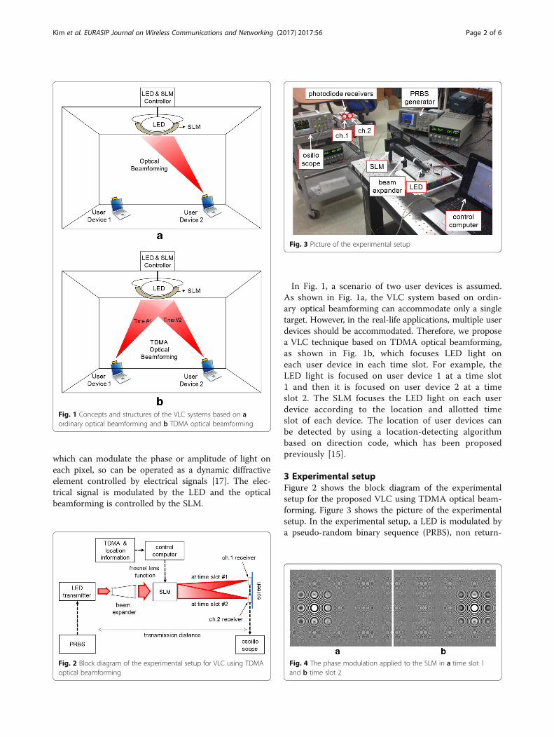
In Fig. 1, a scenario of two user devices is assumed.As shown in Fig. 1a, the VLC system based on ordin-ary optical beamforming can accommodate only a singletarget. However, in the real-life applications, multiple userdevices should be accommodated. Therefore, we proposea VLC technique based on TDMA optical beamforming,as shown in Fig. 1b, which focuses LED light oneach user device in each time slot. For example, theLED light is focused on user device 1 at a time slot1 and then it is focused on user device 2 at a timeslot 2. The SLM focuses the LED light on each userdevice according to the location and allotted timeslot of each device. The location of user devices canbe detected by using a location-detecting algorithmbased on direction code, which has been proposedpreviously [15].
3 Experimental setupFigure 2 shows the block diagram of the experimentalsetup for the proposed VLC using TDMA optical beam-forming. Figure 3 shows the picture of the experimentalsetup. In the experimental setup, a LED is modulated bya pseudo-random binary sequence (PRBS), non return-
Fig. 1 Concepts and structures of the VLC systems based on aordinary optical beamforming and b TDMA optical beamforming
Fig. 2 Block diagram of the experimental setup for VLC using TDMAoptical beamforming
Fig. 3 Picture of the experimental setup
Fig. 4 The phase modulation applied to the SLM in a time slot 1and b time slot 2
Kim et al. EURASIP Journal on Wireless Communications and Networking (2017) 2017:56 Page 2 of 6
to-zero (NRZ) signal. The modulated LED light is passedthrough a beam expander in order to control the beamsize and form it into a parallel ray. The beam expandercan be omitted if the optical design is optimized. Afterthe beam expander, the light goes into a spatial lightmodulator (SLM), which has 800 × 600 translucent liquidcrystal pixels with a pixel pitch of 32 × 32 μm. The size ofthe active area in the SLM is 26.6 × 20.0 mm. The SLM isan optical device that can modulate optical phase oneach pixel in 256 levels (8 control bits), so it can op-erate as a dynamic diffractive element controlled byelectrical signals.A control computer sends a Fresnel lens function to
the SLM according the information of the TDMA timeslot and location of the target devices. This signal modu-lates the phase of SLM pixels and the SLM functionslike a dynamic lens. After passing through the SLM, thelight is beamformed and focused on the optical re-ceivers. OSRAM SFH-213 photodiodes are used for theoptical receivers. Either amplifiers or filters are not usedin the receiver site.The focal length of the optical beamforming is de-
termined by the radius of circles in a Fresnel lensfunction and the wavelength of the light, which isgiven by
L ¼ R21=λ; ð1Þ
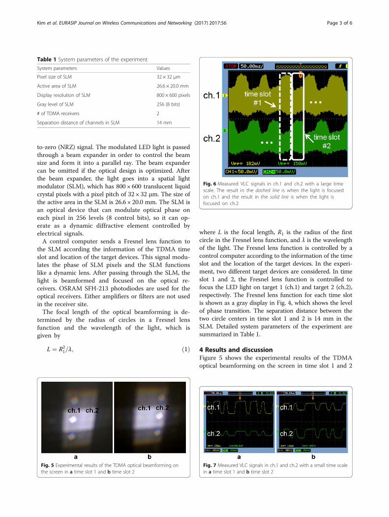
where L is the focal length, R1 is the radius of the firstcircle in the Fresnel lens function, and λ is the wavelengthof the light. The Fresnel lens function is controlled by acontrol computer according to the information of the timeslot and the location of the target devices. In the experi-ment, two different target devices are considered. In timeslot 1 and 2, the Fresnel lens function is controlled tofocus the LED light on target 1 (ch.1) and target 2 (ch.2),respectively. The Fresnel lens function for each time slotis shown as a gray display in Fig. 4, which shows the levelof phase transition. The separation distance between thetwo circle centers in time slot 1 and 2 is 14 mm in theSLM. Detailed system parameters of the experiment aresummarized in Table 1.
4 Results and discussionFigure 5 shows the experimental results of the TDMAoptical beamforming on the screen in time slot 1 and 2
Table 1 System parameters of the experiment
System parameters Values
Pixel size of SLM 32 × 32 μm
Active area of SLM 26.6 × 20.0 mm
Display resolution of SLM 800 × 600 pixels
Gray level of SLM 256 (8 bits)
# of TDMA receivers 2
Separation distance of channels in SLM 14 mm
Fig. 5 Experimental results of the TDMA optical beamforming onthe screen in a time slot 1 and b time slot 2
Fig. 6 Measured VLC signals in ch.1 and ch.2 with a large timescale. The result in the dashed line is when the light is focusedon ch.1 and the result in the solid line is when the light isfocused on ch.2
Fig. 7 Measured VLC signals in ch.1 and ch.2 with a small time scalein a time slot 1 and b time slot 2
Kim et al. EURASIP Journal on Wireless Communications and Networking (2017) 2017:56 Page 3 of 6
at a transmission distance of 90 cm. Because the LEDlight after the beam expander is a parallel ray, the opticalfoot print size is similar to the SLM active area. In timeslot 1 and 2, the light is focused on ch.1 and ch.2, re-spectively. The bright dots in Fig. 3 are the focusedpoints by the TDMA optical beamforming. The faintcrisscross pattern is due to the diffraction of two-dimensional pixel matrix of the SLM. The SLM modelused in the experiment cannot operate as a perfect phasemodulator, so some unmodulated light is still seen onthe screen even after the TDMA optical beamforming. Itshould be noted that the modulation depth of the phasemodulation in the SLM can be adjusted, so the
brightness of the focused points can be controlled. Themodulation depth of the SLM can be controlled ac-cording to the requirement of system or a user. Thisfunction may be important when the LED light is alsoused for illumination.Figure 6 shows the received signals in ch.1 and ch.2
with a large time scale. When the LED light is focusedon ch.1, the signal amplitude of ch.1 increases from 116to 208 mV (5.1 dB gain). The duration time of each timeslot is set to about 50 ms because it is the maximumcontrol rate of the SLM. When it is focused on ch.2, thesignal amplitude of ch.2 increases from 80 to 148 mV(5.3 dB gain). The illumination increases from 60 to
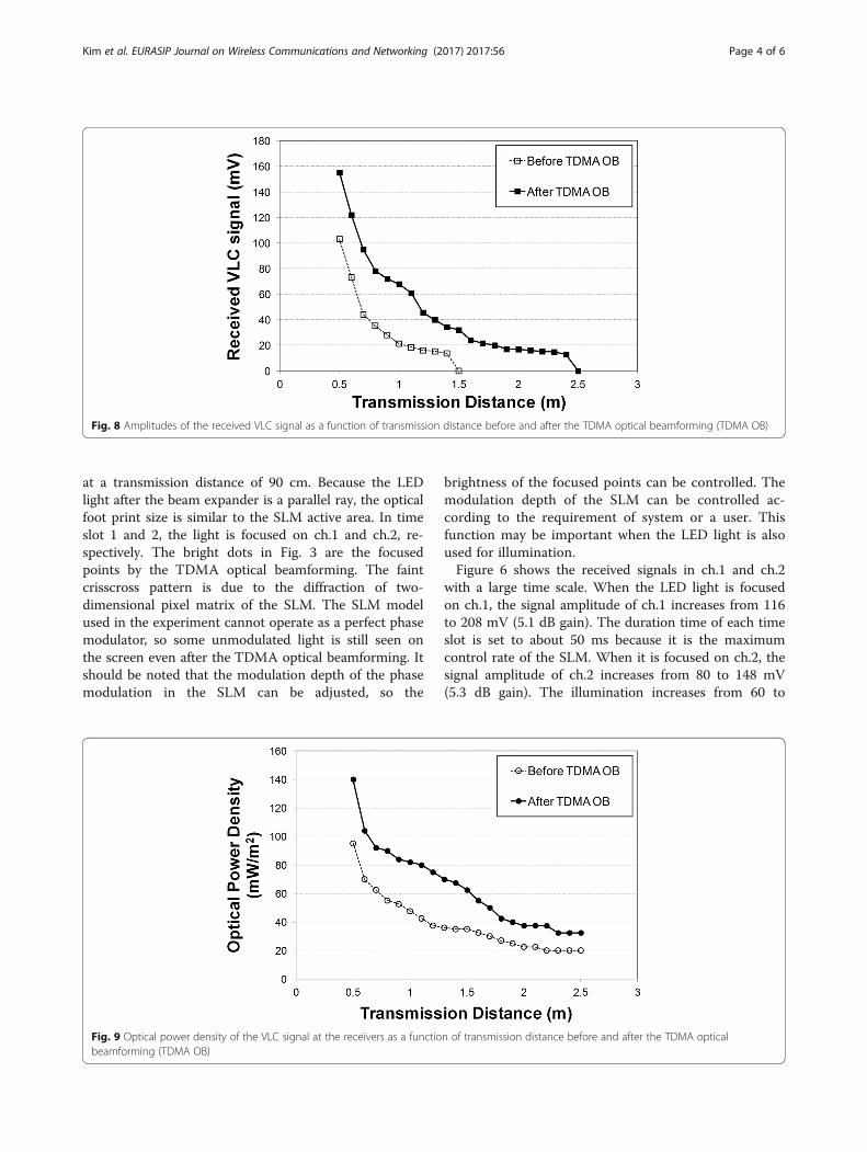
Fig. 8 Amplitudes of the received VLC signal as a function of transmission distance before and after the TDMA optical beamforming (TDMA OB)
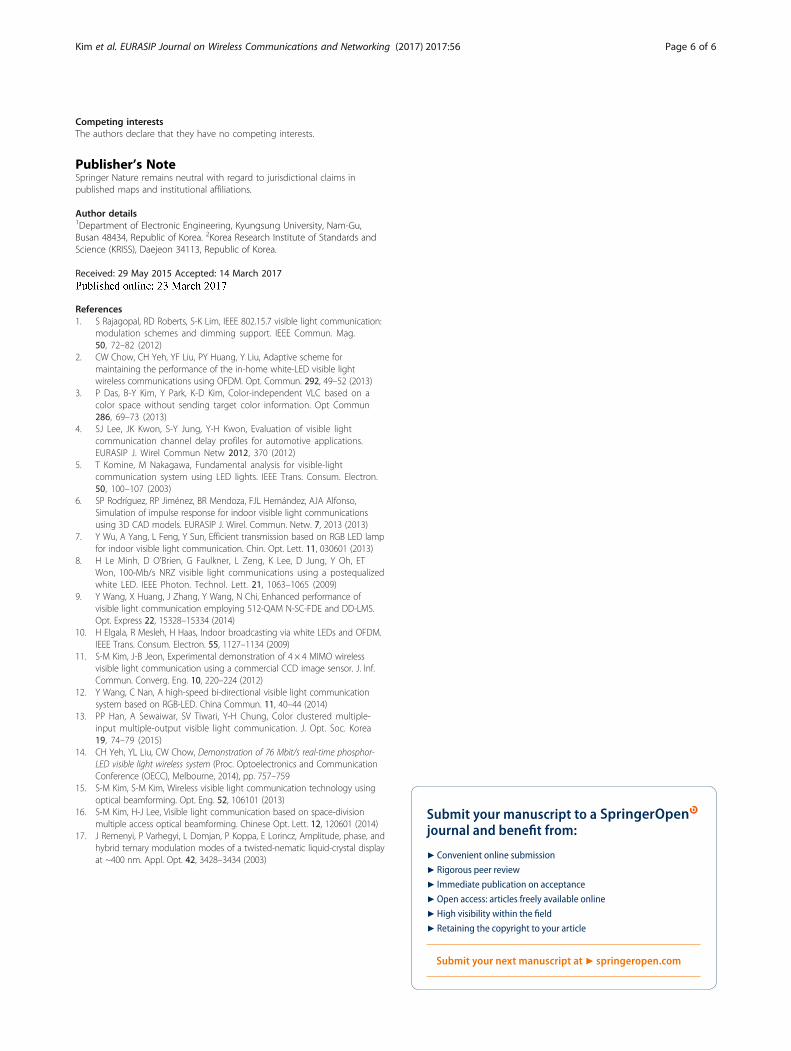
Fig. 9 Optical power density of the VLC signal at the receivers as a function of transmission distance before and after the TDMA opticalbeamforming (TDMA OB)
Kim et al. EURASIP Journal on Wireless Communications and Networking (2017) 2017:56 Page 4 of 6

100 mW/m2 for both channels. The results show thateach channel can enjoy the benefit of optical beamform-ing during its time slot. The received VLC signals with asmall-time scale are shown in Fig. 7. In Fig. 7, it isshown that the VLC operation is successful even whileoptical beamforming is operating.Figure 8 shows the amplitudes of the received VLC
signals as a function of transmission distance beforeand after the TDMA optical beamforming. The resultsshow that amplitudes of the received VLC signals areimproved by 5~10 dB in the transmission distance of60~140 cm thanks to the TDMA optical beamform-ing. The maximum transmission distance increasesfrom 1.4 to 2.4 m thanks to the TDMA optical beam-forming. Figure 9 shows the received optical powerdensity at the receivers as a function of transmissiondistance before and after the TDMA optical beam-forming. In the experimental results, the opticalpower density increases by 2~4 dB in the transmis-sion distance of 80~250 cm thanks to the TDMA op-tical beamforming.Figure 10 shows the bit error rate (BER) performance
of the VLC before and after the TDMA optical beam-forming as a function of transmission distance. If wedefine a BER of <10−3 as a criterion for successful trans-mission, the transmission distance increases from 110 to200 cm with the TDMA optical beamforming. It shouldbe noted that a SLM has a little optical loss even thoughthe gain of the TDMA optical beamforming is higherthan the optical loss.
5 ConclusionsWe have proposed and demonstrated a VLC usingTDMA optical beamforming to accommodate multipleusers in the VLC using optical beamforming. TDMA op-tical beamforming is a technique to focus LED light oneach different target device in each time slot. Our resultshave shown that each user device can enjoy the benefitof the optical beamforming during its time slot with theTDMA optical beamforming. The VLC signal amplitudeof each channel increases by 5~10 dB, the optical powerdensity of the VLC signal increases by 2~4 dB, and thetransmission distance increases from 110 to 200 cm withthe TDMA optical beamforming. Since the proposedtechnique can increase the performance of VLC effi-ciently and does not depend on the electrical modulationformats, it can be widely used in various applications.
AcknowledgementsThis research was supported by the Basic Science Research Program throughthe National Research Foundation of Korea (NRF) funded by the Ministry ofScience, ICT and Future Planning (No. NRF-2012M3C1A1048865 and NRF-2015R1C1A1A01052543).
FundingThis research was supported by the Basic Science Research Program throughthe National Research Foundation of Korea (NRF) funded by the Ministry ofScience, ICT and Future Planning (No. NRF-2012M3C1A1048865 and NRF-2015R1C1A1A01052543).
Authors’ contributionsS-MK is the main writer of this paper. He proposed the main idea, conductedthe experiment, and analyzed it. M-WB conducted the experiment with S-MK.SHN assisted the experiment. All authors read and approved the finalmanuscript.
Fig. 10 BER performance before and after the TDMA optical beamforming (TDMA OB)
Kim et al. EURASIP Journal on Wireless Communications and Networking (2017) 2017:56 Page 5 of 6
Competing interestsThe authors declare that they have no competing interests.
Publisher’s NoteSpringer Nature remains neutral with regard to jurisdictional claims inpublished maps and institutional affiliations.
Author details1Department of Electronic Engineering, Kyungsung University, Nam-Gu,Busan 48434, Republic of Korea. 2Korea Research Institute of Standards andScience (KRISS), Daejeon 34113, Republic of Korea.
Received: 29 May 2015 Accepted: 14 March 2017
References1. S Rajagopal, RD Roberts, S-K Lim, IEEE 802.15.7 visible light communication:
modulation schemes and dimming support. IEEE Commun. Mag.50, 72–82 (2012)
2. CW Chow, CH Yeh, YF Liu, PY Huang, Y Liu, Adaptive scheme formaintaining the performance of the in-home white-LED visible lightwireless communications using OFDM. Opt. Commun. 292, 49–52 (2013)
3. P Das, B-Y Kim, Y Park, K-D Kim, Color-independent VLC based on acolor space without sending target color information. Opt Commun286, 69–73 (2013)
4. SJ Lee, JK Kwon, S-Y Jung, Y-H Kwon, Evaluation of visible lightcommunication channel delay profiles for automotive applications.EURASIP J. Wirel Commun Netw 2012, 370 (2012)
5. T Komine, M Nakagawa, Fundamental analysis for visible-lightcommunication system using LED lights. IEEE Trans. Consum. Electron.50, 100–107 (2003)
6. SP Rodríguez, RP Jiménez, BR Mendoza, FJL Hernández, AJA Alfonso,Simulation of impulse response for indoor visible light communicationsusing 3D CAD models. EURASIP J. Wirel. Commun. Netw. 7, 2013 (2013)
7. Y Wu, A Yang, L Feng, Y Sun, Efficient transmission based on RGB LED lampfor indoor visible light communication. Chin. Opt. Lett. 11, 030601 (2013)
8. H Le Minh, D O’Brien, G Faulkner, L Zeng, K Lee, D Jung, Y Oh, ETWon, 100-Mb/s NRZ visible light communications using a postequalizedwhite LED. IEEE Photon. Technol. Lett. 21, 1063–1065 (2009)
9. Y Wang, X Huang, J Zhang, Y Wang, N Chi, Enhanced performance ofvisible light communication employing 512-QAM N-SC-FDE and DD-LMS.Opt. Express 22, 15328–15334 (2014)
10. H Elgala, R Mesleh, H Haas, Indoor broadcasting via white LEDs and OFDM.IEEE Trans. Consum. Electron. 55, 1127–1134 (2009)
11. S-M Kim, J-B Jeon, Experimental demonstration of 4 × 4 MIMO wirelessvisible light communication using a commercial CCD image sensor. J. Inf.Commun. Converg. Eng. 10, 220–224 (2012)
12. Y Wang, C Nan, A high-speed bi-directional visible light communicationsystem based on RGB-LED. China Commun. 11, 40–44 (2014)
13. PP Han, A Sewaiwar, SV Tiwari, Y-H Chung, Color clustered multiple-input multiple-output visible light communication. J. Opt. Soc. Korea19, 74–79 (2015)
14. CH Yeh, YL Liu, CW Chow, Demonstration of 76 Mbit/s real-time phosphor-LED visible light wireless system (Proc. Optoelectronics and CommunicationConference (OECC), Melbourne, 2014), pp. 757–759
15. S-M Kim, S-M Kim, Wireless visible light communication technology usingoptical beamforming. Opt. Eng. 52, 106101 (2013)
16. S-M Kim, H-J Lee, Visible light communication based on space-divisionmultiple access optical beamforming. Chinese Opt. Lett. 12, 120601 (2014)
17. J Remenyi, P Varhegyi, L Domjan, P Koppa, E Lorincz, Amplitude, phase, andhybrid ternary modulation modes of a twisted-nematic liquid-crystal displayat ~400 nm. Appl. Opt. 42, 3428–3434 (2003)
Submit your manuscript to a journal and benefi t from:
7 Convenient online submission
7 Rigorous peer review
7 Immediate publication on acceptance
7 Open access: articles freely available online
7 High visibility within the fi eld
7 Retaining the copyright to your article
Submit your next manuscript at 7 springeropen.com
Kim et al. EURASIP Journal on Wireless Communications and Networking (2017) 2017:56 Page 6 of 6