Visible continuous emission from a silica microphotonic device by third-harmonic generation
6
ARTICLES Visible continuous emission from a silica microphotonic device by third-harmonic generation TAL CARMON AND KERRY J. VAHALA* California Institute of Technology, 1200 E. California Boulevard, Pasadena, California 91125, USA *e-mail: [email protected] Published online: 7 May 2007; doi:10.1038/nphys601 Nonlinear harmonic generation is widely used to extend the emission wavelength of laser sources. These devices typically require high peak powers to generate sufficient nonlinear optical response. Here, we demonstrate experimentally and analyse theoretically continuous-wave, visible emission from a silica microresonator on a silicon chip by third-harmonic generation. Emission is observed with pump powers of less than 300 μW, and is verified to scale cubically with pump power. We also observe third-order sum-frequency generation and mixing of the pump with a concomitant Raman laser within the same structure, giving rise to emission of various colours. In addition to providing low-power operation, this result opens the possibility of silicon microphotonic emitters spanning all the way down to the ultraviolet and operating continuously. Silica glass has laid the foundation of the photonic revolution over the past decades as its durability and low optical loss over a broad spectral window has enabled light transmission over long distances by optical fibres. In this capacity, silica’s role is both passive and active as erbium-based-fibre amplifiers 1–3 are essential for signal regeneration. Moreover, silica is a mainstay of optical technology on-a-chip 4,5 , including recent efforts to create new complementary metal–oxide–semiconductor (CMOS)- compatible optical device technologies (that is, silicon photonics). Furthermore, photonic-crystal fibre 6,7 has paved the way for new phenomena and technologies useful for manipulation of light. In these new frontiers of silica-based applications, important underlying themes are to leverage a perfected technology (modern telecommunications in the 1.5 μm band and CMOS electronics) for potential new gains. In this paper, this idea is extended in a new way demonstrating a silica-on-silicon microplatform that links the telecommunications window to the visible spectrum. Here, we demonstrate experimentally for the first time broadly tuneable, visible, continuous emission from a silica microphotonic device by third-harmonic (TH) generation. The micro-emitter is a CMOS-compatible silicon-photonic-based device, made of pure silica on a silicon chip. Third-harmonic emission in silica has been studied in the context of optical fibres 8 . However, the principle of operation in the current work extends previous work on nonlinear resonant enhancement in high-quality-factor optical microcavities. In particular, we build on the work of Chang who pioneered visible emission by using the TH nonlinearity in droplets 9–11 . Our work also extends other liquid droplet work 12 as well as other nonlinear phenomena studied in liquids 13,14 and solid spheres 15 and later in toroidal resonators 16 . The visible TH is different to that of semiconductor sources 17 . Third-harmonic light is observable at only 300 μW of pump power operating at room temperature. Phase matching is achieved by compensation of the material dispersion by the dispersion of the cavity modes. The ability to produce 500 nm light from a 1,500 nm CCD Microscope Pump in (~1,500 nm) Spectrum analysers Monitor (top view) Monitor (side view) Power meters 26 μm Ring cavity Monitor a b Figure 1 Experimental set-up. a, Infrared pump (of 300 kHz bandwidth) evanescently coupled to a microring cavity by a tapered fibre, generating visible TH emission. The TH emission is monitored by a camera, detector and a spectrum analyser. b, Left: The tapered fibre via which the pump is evanescently coupled into the ring cavity. Right: Top and side view of the cavity; TH power is visible in the side view. 430 nature physics VOL 3 JUNE 2007 www.nature.com/naturephysics
Transcript of Visible continuous emission from a silica microphotonic device by third-harmonic generation

ARTICLES
Visible continuous emission froma silica microphotonic device bythird-harmonic generation
TAL CARMON AND KERRY J. VAHALA*California Institute of Technology, 1200 E. California Boulevard, Pasadena, California 91125, USA*e-mail: [email protected]
Published online: 7 May 2007; doi:10.1038/nphys601
Nonlinear harmonic generation is widely used to extend the emission wavelength of laser sources. These devices typically requirehigh peak powers to generate sufficient nonlinear optical response. Here, we demonstrate experimentally and analyse theoreticallycontinuous-wave, visible emission from a silica microresonator on a silicon chip by third-harmonic generation. Emission is observedwith pump powers of less than 300μW, and is verified to scale cubically with pump power. We also observe third-order sum-frequencygeneration and mixing of the pump with a concomitant Raman laser within the same structure, giving rise to emission of variouscolours. In addition to providing low-power operation, this result opens the possibility of silicon microphotonic emitters spanningall the way down to the ultraviolet and operating continuously.
Silica glass has laid the foundation of the photonic revolutionover the past decades as its durability and low optical loss overa broad spectral window has enabled light transmission overlong distances by optical fibres. In this capacity, silica’s role isboth passive and active as erbium-based-fibre amplifiers1–3 areessential for signal regeneration. Moreover, silica is a mainstayof optical technology on-a-chip4,5, including recent efforts tocreate new complementary metal–oxide–semiconductor (CMOS)-compatible optical device technologies (that is, silicon photonics).Furthermore, photonic-crystal fibre6,7 has paved the way for newphenomena and technologies useful for manipulation of light.In these new frontiers of silica-based applications, importantunderlying themes are to leverage a perfected technology (moderntelecommunications in the 1.5 μm band and CMOS electronics) forpotential new gains. In this paper, this idea is extended in a newway demonstrating a silica-on-silicon microplatform that links thetelecommunications window to the visible spectrum.
Here, we demonstrate experimentally for the first time broadlytuneable, visible, continuous emission from a silica microphotonicdevice by third-harmonic (TH) generation. The micro-emitter isa CMOS-compatible silicon-photonic-based device, made of puresilica on a silicon chip. Third-harmonic emission in silica has beenstudied in the context of optical fibres8. However, the principle ofoperation in the current work extends previous work on nonlinearresonant enhancement in high-quality-factor optical microcavities.In particular, we build on the work of Chang who pioneeredvisible emission by using the TH nonlinearity in droplets9–11. Ourwork also extends other liquid droplet work12 as well as othernonlinear phenomena studied in liquids13,14 and solid spheres15 andlater in toroidal resonators16. The visible TH is different to that ofsemiconductor sources17.
Third-harmonic light is observable at only 300 μW of pumppower operating at room temperature. Phase matching is achievedby compensation of the material dispersion by the dispersion of thecavity modes. The ability to produce 500 nm light from a 1,500 nm
CCD
Microscope
Pump in(~1,500 nm)
Spectrum analysers
Monitor (top view)
Monitor (side view)
Power meters
26 μm
Ringcavity
Monitora
b
Figure 1 Experimental set-up. a, Infrared pump (of 300 kHz bandwidth)evanescently coupled to a microring cavity by a tapered fibre, generating visible THemission. The TH emission is monitored by a camera, detector and a spectrumanalyser. b, Left: The tapered fibre via which the pump is evanescently coupled intothe ring cavity. Right: Top and side view of the cavity; TH power is visible in theside view.
430 nature physics VOL 3 JUNE 2007 www.nature.com/naturephysics
Untitled-1 1 19/5/07, 11:53:51 am
ARTICLES
400 500 600 700 1,200 1,400 1,6001,000Wavelength (nm)
Pow
er (a
.u.)
00
10
20
250 500 750 1,000
Power in (μW)
Pow
er o
ut (a
.u.)
a
b
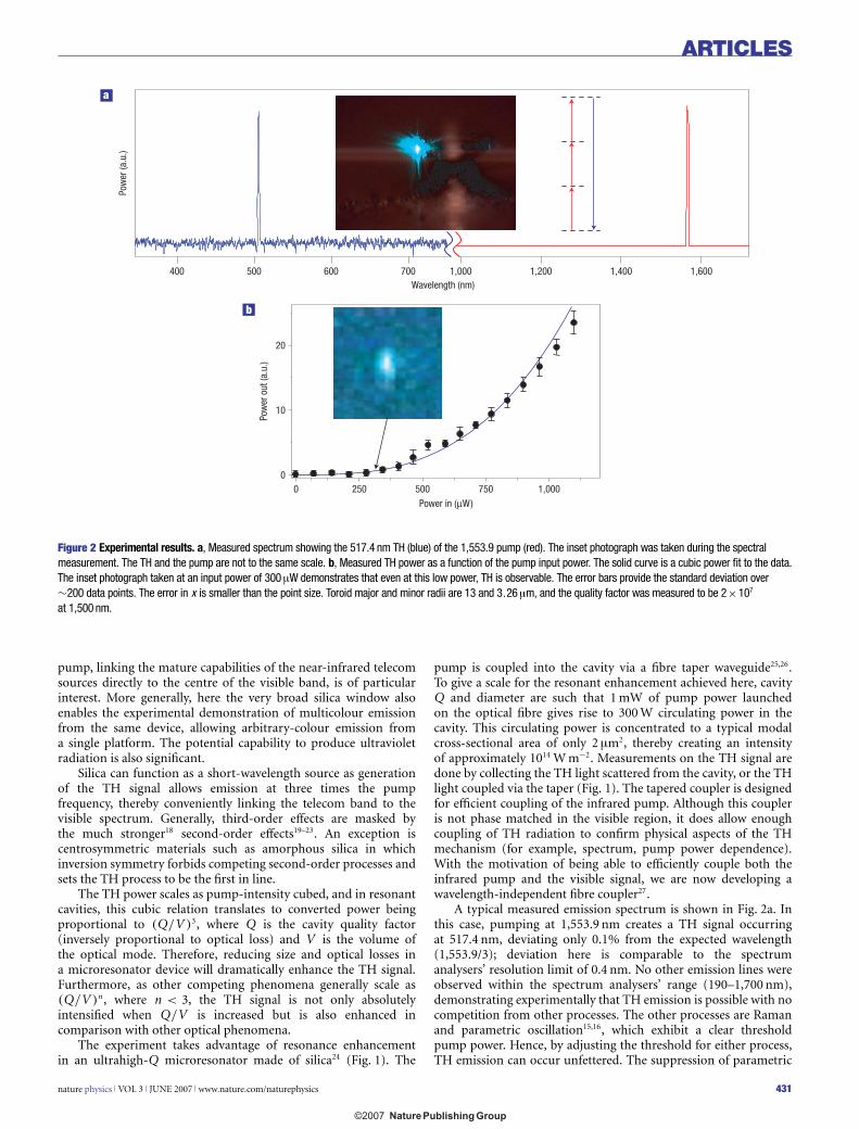
Figure 2 Experimental results. a, Measured spectrum showing the 517.4 nm TH (blue) of the 1,553.9 pump (red). The inset photograph was taken during the spectralmeasurement. The TH and the pump are not to the same scale. b, Measured TH power as a function of the pump input power. The solid curve is a cubic power fit to the data.The inset photograph taken at an input power of 300μW demonstrates that even at this low power, TH is observable. The error bars provide the standard deviation over∼200 data points. The error in x is smaller than the point size. Toroid major and minor radii are 13 and 3.26μm, and the quality factor was measured to be 2×10⁷
at 1,500 nm.
pump, linking the mature capabilities of the near-infrared telecomsources directly to the centre of the visible band, is of particularinterest. More generally, here the very broad silica window alsoenables the experimental demonstration of multicolour emissionfrom the same device, allowing arbitrary-colour emission froma single platform. The potential capability to produce ultravioletradiation is also significant.
Silica can function as a short-wavelength source as generationof the TH signal allows emission at three times the pumpfrequency, thereby conveniently linking the telecom band to thevisible spectrum. Generally, third-order effects are masked bythe much stronger18 second-order effects19–23. An exception iscentrosymmetric materials such as amorphous silica in whichinversion symmetry forbids competing second-order processes andsets the TH process to be the first in line.
The TH power scales as pump-intensity cubed, and in resonantcavities, this cubic relation translates to converted power beingproportional to (Q/V )3, where Q is the cavity quality factor(inversely proportional to optical loss) and V is the volume ofthe optical mode. Therefore, reducing size and optical losses ina microresonator device will dramatically enhance the TH signal.Furthermore, as other competing phenomena generally scale as(Q/V )n, where n < 3, the TH signal is not only absolutelyintensified when Q/V is increased but is also enhanced incomparison with other optical phenomena.
The experiment takes advantage of resonance enhancementin an ultrahigh-Q microresonator made of silica24 (Fig. 1). The
pump is coupled into the cavity via a fibre taper waveguide25,26.To give a scale for the resonant enhancement achieved here, cavityQ and diameter are such that 1 mW of pump power launchedon the optical fibre gives rise to 300 W circulating power in thecavity. This circulating power is concentrated to a typical modalcross-sectional area of only 2 μm2, thereby creating an intensityof approximately 1014 W m−2. Measurements on the TH signal aredone by collecting the TH light scattered from the cavity, or the THlight coupled via the taper (Fig. 1). The tapered coupler is designedfor efficient coupling of the infrared pump. Although this coupleris not phase matched in the visible region, it does allow enoughcoupling of TH radiation to confirm physical aspects of the THmechanism (for example, spectrum, pump power dependence).With the motivation of being able to efficiently couple both theinfrared pump and the visible signal, we are now developing awavelength-independent fibre coupler27.
A typical measured emission spectrum is shown in Fig. 2a. Inthis case, pumping at 1,553.9 nm creates a TH signal occurringat 517.4 nm, deviating only 0.1% from the expected wavelength(1,553.9/3); deviation here is comparable to the spectrumanalysers’ resolution limit of 0.4 nm. No other emission lines wereobserved within the spectrum analysers’ range (190–1,700 nm),demonstrating experimentally that TH emission is possible with nocompetition from other processes. The other processes are Ramanand parametric oscillation15,16, which exhibit a clear thresholdpump power. Hence, by adjusting the threshold for either process,TH emission can occur unfettered. The suppression of parametric
nature physics VOL 3 JUNE 2007 www.nature.com/naturephysics 431
Untitled-1 2 19/5/07, 11:53:53 am
ARTICLES
a c
b d
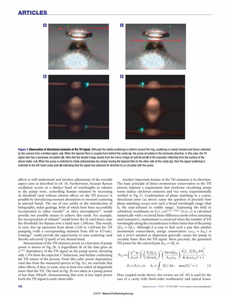
Figure 3 Observation of directional emission of the TH signal. Although the visible scattering is uniform around the ring, scattering is mainly forward and hence collectedby the camera from a limited region. a,b, When the tapered fibre is coupled from behind the cavity (a), the pump circulates in the clockwise direction. In this case, the THsignal also has a clockwise circulation (b). Note that the double image results from the mirror image (in both b and d) of the resonator reflecting from the surface of thesilicon wafer. c,d, When the pump is switched to rotate anticlockwise (by simply moving the tapered fibre to the other side of the cavity (c)), then the signal scattering isswitched to the left-hand cavity side (d) indicating that the signal has switched its direction to co-circulate with the pump.
effects is well understood and involves adjustment of the toroidalaspect ratio as described in ref. 16. Furthermore, because Ramanoscillation occurs in a distinct band of wavelengths in relationto the pump wave, controlling Raman emission by increasingits threshold (and without adverse effects on the TH process) ispossible by introducing resonant absorption or resonant scatteringin selected bands. The use of rare earths or the introduction ofholographic index gratings, both of which have been successfullyincorporated in either toroids28 or silica microspheres29, wouldprovide two possible means to achieve this result. For example,the incorporation of erbium28 would lower the Q (and hence raisethe threshold) for Raman over a band near 1,500 nm. This would,in turn, free up operation from about 1,320 to 1,420 nm for THpumping (with a corresponding emission from 450 to 473 nm).Gratings29 could provide the opportunity to tune scattering (andthereby selectively Q spoil) of any desired band.
Measurement of the TH emission power as a function of pumppower is shown in Fig. 2b. A logarithmic fit of the data gives anx2.954 dependency of the TH signal on the pump power, deviatingonly 1.5% from the expected x3 behaviour, and further confirmingthe TH nature of the process. From this cubic power dependency(and also from the measured spectra in Fig. 2a), we conclude thatother effects, if they co-exist, were at least two orders of magnitudelower than the TH. The inset in Fig. 2b was taken at a pump powerof less than 300 μW, demonstrating that even at low input powerlevels the TH signal is easily observable.
Another important feature of the TH emission is its direction.The basic principle of linear momentum conservation in the THprocess imposes a requirement that clockwise circulating pumpwaves induce clockwise emission and vice versa (experimentallyverified in Fig. 3). Confirmation of phase matching in a coarse,directional sense (as above) raises the question of precisely howphase matching occurs over such a broad wavelength range (thatis, the near-infrared to visible range). Expressing the field incylindrical coordinates as Ei(r, z)e[i(ωi t−βi φ)] (Ei(r, z) is calculatednumerically with a vectorial finite-difference mode solver assumingaxial symmetry), momentum is conserved when the number of THwavelengths along the circumference is three times that of the pump(βTH = 3βp). Although it is easy to find such a pair that satisfiesmomentum conservation, energy conservation (ωTH = 3ωp) isnot a priori satisfied as dispersion generally causes the pump tocirculate faster than the TH signal. More precisely, the generatedTH power for the selected pair βTH = 3βp is:
PTH =(
χ(3)η0
2ε0n2
)2(PpQplp
2πrnAp
)3(2πrnQTH
ATHlTH
) 4∣∣∣∫r,z
E3pE∗
TH dA∣∣∣2
4(�ωτTH)2 +1,
Ei = Ei(r,z), Ai =∫
r,z
|Ei|2 dA, max|Ei|2 = 1. (1)
Here coupled-mode theory (for review, see ref. 30) is used for thecase of a cavity with third-order nonlinearity and optical losses.
432 nature physics VOL 3 JUNE 2007 www.nature.com/naturephysics
Untitled-1 3 19/5/07, 11:53:58 am
ARTICLES
–0.15
0
0.10
0.20
450 500TH wavelength (nm)
Infrared pump mode
High index
Low index
The seventh visible mode
550
First TH mode
Second TH mode
(3pu
mp
–TH
)/pu
mp
ωω
ω
(3pu
mp
–TH
)/pu
mp
ωω
ω
–0.1
0
0.15 0.20 0.25
0.1
18
Pote
ntia
l
19
Radius (μm), inner core thickness (μm)20 21
Δ
Δ
R = 20 μm
R = 2.5 μm
R = 18.8 μm
a b c
d e f
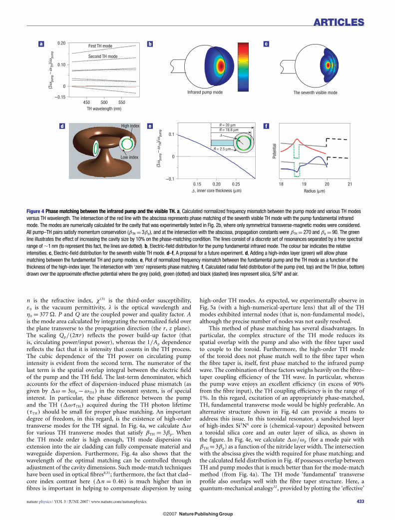
Figure 4 Phase matching between the infrared pump and the visible TH. a, Calculated normalized frequency mismatch between the pump mode and various TH modesversus TH wavelength. The intersection of the red line with the abscissa represents phase matching of the seventh visible TH mode with the pump fundamental infraredmode. The modes are numerically calculated for the cavity that was experimentally tested in Fig. 2b, where only symmetrical transverse-magnetic modes were considered.All pump–TH pairs satisfy momentum conservation (βTH = 3βp), and at the intersection with the abscissa, propagation constants were βTH = 270 and βp = 90. The greenline illustrates the effect of increasing the cavity size by 10% on the phase-matching condition. The lines consist of a discrete set of resonances separated by a free spectralrange of ∼1 nm (to represent this fact, the lines are dotted). b, Electric-field distribution for the pump fundamental infrared mode. The colour bar indicates the relativeintensities. c, Electric-field distribution for the seventh visible TH mode. d–f, A proposal for a future experiment. d, Adding a high-index layer (green) will allow phasematching between the fundamental TH and pump modes. e, Plot of normalized frequency mismatch between the fundamental pump and the TH mode as a function of thethickness of the high-index layer. The intersection with ‘zero’ represents phase matching. f, Calculated radial field distribution of the pump (red, top) and the TH (blue, bottom)drawn over the approximate effective potential where the grey (solid), green (dotted) and black (dashed) lines represent silica, Si3N4 and air.
n is the refractive index, χ(3) is the third-order susceptibility,ε0 is the vacuum permittivity, l is the optical wavelength andη0 = 377 . P and Q are the coupled power and quality factor. Ais the mode area calculated by integrating the normalized field overthe plane transverse to the propagation direction (the r, z plane).The scaling Qp/(2πr) reflects the power build-up factor (thatis, circulating power/input power), whereas the 1/Ap dependencereflects the fact that it is intensity that counts in the TH process.The cubic dependence of the TH power on circulating pumpintensity is evident from the second term. The numerator of thelast term is the spatial overlap integral between the electric fieldof the pump and the TH field. The last-term denominator, whichaccounts for the effect of dispersion-induced phase mismatch (asgiven by �ω = 3ωp − ωTH) in the resonant system, is of specialinterest. In particular, the phase difference between the pumpand the TH (�ωτTH) acquired during the TH photon lifetime(τTH) should be small for proper phase matching. An importantdegree of freedom, in this regard, is the existence of high-ordertransverse modes for the TH signal. In Fig. 4a, we calculate �ωfor various TH transverse modes that satisfy βTH = 3βp. Whenthe TH mode order is high enough, TH mode dispersion viaextension into the air cladding can fully compensate material andwaveguide dispersion. Furthermore, Fig. 4a also shows that thewavelength of the optimal matching can be controlled throughadjustment of the cavity dimensions. Such mode-match techniqueshave been used in optical fibres8,31; furthermore, the fact that clad–core index contrast here (�n = 0.46) is much higher than infibres is important in helping to compensate dispersion by using
high-order TH modes. As expected, we experimentally observe inFig. 5a (with a high-numerical-aperture lens) that all of the THmodes exhibited internal nodes (that is, non-fundamental mode),although the precise number of nodes was not easily resolved.
This method of phase matching has several disadvantages. Inparticular, the complex structure of the TH mode reduces itsspatial overlap with the pump and also with the fibre taper usedto couple to the toroid. Furthermore, the high-order TH modeof the toroid does not phase match well to the fibre taper whenthe fibre taper is, itself, first phase matched to the infrared pumpwave. The combination of these factors weighs heavily on the fibre–taper coupling efficiency of the TH wave. In particular, whereasthe pump wave enjoys an excellent efficiency (in excess of 90%from the fibre input), the TH coupling efficiency is in the range of1%. In this regard, excitation of an appropriately phase-matched,TH, fundamental transverse mode would be highly preferable. Analternative structure shown in Fig. 4d can provide a means toaddress this issue. In this toroidal resonator, a sandwiched layerof high-index Si3N4 core is (chemical-vapour) deposited betweena toroidal silica core and an outer layer of silica, as shown inthe figure. In Fig. 4e, we calculate �ω/ωp (for a mode pair withβTH =3βp) as a function of the nitride layer width. The intersectionwith the abscissa gives the width required for phase matching; andthe calculated field distribution in Fig. 4f possesses overlap betweenTH and pump modes that is much better than for the mode-matchmethod (from Fig. 4a). The TH mode ‘fundamental’ transverseprofile also overlaps well with the fibre taper structure. Here, aquantum-mechanical analogy32, provided by plotting the ‘effective’
nature physics VOL 3 JUNE 2007 www.nature.com/naturephysics 433
Untitled-1 4 19/5/07, 11:54:03 am
ARTICLES
1 μm
b
a
c
d
Figure 5 Experimental observation of internal modes and multicolour generation. a, Use of a high-numerical-aperture objective allows imaging internal node structure inthe TH mode. We note that the fine mode structures are difficult to image. The white lines represent the approximate geometry of the toroid cross-section. b, A unidirectionalsignal is generated by a unidirectional pump. c, Two, identical, counter-rotating pumps give rise to two counter-rotating signals. d, Two different pumps that also counterrotate are giving rise to two counter-rotating signals of different colour.
a
400 500 600 700 1,000 1,200 1,400 1,600
Pow
er (a
.u.)
Wavelength (nm)
542
nm
Sum
-fre
quen
cy g
ener
atio
n
Pum
p 1
Pum
p 2
1,55
3 nm
1,67
4 nm
Figure 6 Measured spectra showing third-order sum-frequency generation where two 1,674nm photons are summed with one 1,553nm photon to generateemission at 542nm. The inset photograph was taken during the spectral measurement; the signal and pump are not to the same scale.
optical potential (along the radial direction) perceived by themodes in the silica/nitride microcavity, is useful in understandingthe function of the nitride layer. Using the wave equation in
spherical coordinates to approximate the situation, Fig. 4f reveals adouble-welled potential in which the TH wave populates the outerwell, whereas the pump wave populates the (high-index silicon
434 nature physics VOL 3 JUNE 2007 www.nature.com/naturephysics
Untitled-1 5 19/5/07, 11:54:09 am

ARTICLES
nitride) inner well (and hence is selectively slowed down). Usingequation (1), the efficiency for this Si3N4 core device (Fig. 4d) canbe as high as 53% for a 140 μW pump (Qp is the one measuredin Fig. 2b; QTH is assumed to be equal to Qp and the wavelength-dependent refractive indices for the Si3N4 and SiO2 were taken fromref. 33). This efficiency is high enough that pump depletion (whichhas not been included in the analysis) would undoubtedly be afactor even at these relatively low input powers. Developing thismultilayer technology is beyond the scope of this article and is amatter for future research.
The broad silica transmission window has the virtue ofnot limiting the device to a single colour output. This isshown experimentally in Fig. 5b–d where several colours arephotographed from the same device. Simultaneous, two-colouremission is also shown in Fig. 5d. In a similar manner, more thantwo colours could be generated within the same device to synthesizearbitrary-colour emission originating from a single platform. Yetanother degree of freedom here is the possibility to generate notonly the TH signal but also the third-order sum frequency fromtwo (or even three) different pump wavelengths: one such examplemeasured here (Fig. 6) is the generation of emission at 544 nmby summation of two different frequencies from a pump andconcomitant Raman signal (2/1,674+1/1,553 = 1/544).
To summarize, we demonstrated a durable device that exploitsTH generation for continuous visible emission. In addition to theobservation of continuous-wave TH emission, we did not observeany Q degradation or damage to the devices, even using pumpintensities as high as 1 W (using an erbium-fibre amplifier toboost the power of the pump laser). Although the devices usedhere are currently unique in terms of providing ultrahigh Q ina wafer-compatible, microscale platform, the sustained trend inQ/V microcavity performance34–36 suggests that similar devicesover a wide range of platform types will soon be possible. Inparticular, a non-reflow strategy to achieve Q factors of 50 millionhas recently been demonstrated37. Such an approach simplifiesprocess compatibility with CMOSs. Recent advances in high-Qphotonic-crystal microresonators38 are also intriguing, as suchstructures achieve very high Q/V and could potentially providedispersion engineering techniques useful to address phase matchingof the pump and TH signal. Therefore, we consider the presentembodiment demonstrated here as being just one of manypossibilities that will be enabled by continued progress within thebroad field of microcavity research. Finally, a natural extension ofthis work will be the use of the broad silica transmission band togenerate tuneable, ultraviolet emission using the present device.Because of the cubic pump-band Q-factor dependence, efficientemission into the deep-ultraviolet band (for example, 780 nmsources to 260 nm TH) should be possible using this silica-basedstructure. Furthermore, the emitting platform is not limited to bemade of silica and, in principle, any transparent centrosymmetricmaterial can be used; among these materials, CaF2 is of particularinterest as high-Q cavities made of this material (CaF2) werealready demonstrated experimentally39 and it possesses capabilitiesfor extreme-ultraviolet emission as its transparency window goesdown to 160 nm. In the future, replacing the 1,550 nm source witha 780 nm input to obtain ultraviolet TH will also allow shrinking ofthe cavity by the same ratio without suffering increased radiationloss. As TH scales with (Ql/V )3, this size reduction means ahigher efficiency conversion (assuming similar Q) when comparedwith the current visible result. Even though current Q factors arenot limited by silica’s intrinsic loss, this component of Q willprobably be higher in the ultraviolet region. Hence, the samesize scaling effect can help to extend efficient operation into theultraviolet region.
Received 11 December 2006; accepted 29 March 2007; published 7 May 2007.
References1. Desurvire, E. Erbium-Doped Fiber Amplifiers: Principles and Applications (Wiley, New York, 1994).2. Becker, P. C., Olsson, N. A. & Simpson, J. R. Erbium-Doped Fiber Amplifiers: Fundamentals and
Technology (Academic, San Diego, 1999).3. Digonnet, M. J. F. Rare-Earth-Doped Fiber Lasers and Amplifiers 2nd edn (Dekker, New York, 2001).4. Boyraz, O. & Jalali, B. Demonstration of a silicon Raman laser. Opt. Express 12, 5269–5273 (2004).5. Liu, A. S. et al. A high-speed silicon optical modulator based on a metal–oxide–semiconductor
capacitor. Nature 427, 615–618 (2004).6. Knight, J. C. Photonic crystal fibres. Nature 424, 847–851 (2003).7. Knight, J. C., Birks, T. A., Russell, P. S. & Atkin, D. M. All-silica single-mode optical fiber with
photonic crystal cladding. Opt. Lett. 21, 1547–1549 (1996).8. Bufetov, I. A., Grekov, M. V., Golant, K. M., Dianov, E. M. & Khrapko, R. R. Ultraviolet-light
generation in nitrogen-doped silica fiber. Opt. Lett. 22, 1394–1396 (1997).9. Acker, W. P., Leach, D. H. & Chang, R. K. Third-order optical sum-frequency generation in
micrometer-sized liquid droplets. Opt. Lett. 14, 402–404 (1989).10. Leach, D. H., Acker, W. P. & Chang, R. K. Effect of the phase-velocity and spatial overlap of spherical
resonances on sum-frequency generation in droplets. Opt. Lett. 15, 894–896 (1990).11. Leach, D. H., Chang, R. K., Acker, W. P. & Hill, S. C. Third-order sum-frequency generation in
droplets—experimental results. J. Opt. Soc. Am. B 10, 34–45 (1993).12. Kasparian, J. et al. Angular dependences of third harmonic generation from microdroplets. Phys. Rev.
Lett. 78, 2952–2955 (1997).13. Qian, S. X. & Chang, R. K. Multiorder stokes emission from micrometer-size droplets. Phys. Rev. Lett.
56, 926–929 (1986).14. Lin, H. B., Eversole, J. D. & Campillo, A. J. Continuous-wave stimulated Raman-scattering in
microdroplets. Opt. Lett. 17, 828–830 (1992).15. Spillane, S. M., Kippenberg, T. J. & Vahala, K. J. Ultralow-threshold Raman laser using a spherical
dielectric microcavity. Nature 415, 621–623 (2002).16. Kippenberg, T. J., Spillane, S. M. & Vahala, K. J. Kerr-nonlinearity optical parametric oscillation in an
ultrahigh-Q toroid microcavity. Phys. Rev. Lett. 93, 083904 (2004).17. Ponce, F. A. & Bour, D. P. Nitride-based semiconductors for blue and green light-emitting devices.
Nature 386, 351–359 (1997).18. Boyd, R. W. Nonlinear Optics 2nd edn (Academic, San Diego, 2003).19. Franken, P. A., Weinreich, G., Peters, C. W. & Hill, A. E. Generation of optical harmonics. Phys. Rev.
Lett. 7, 118–120 (1961).20. Osterberg, U. & Margulis, W. Dye-laser pumped by Nd-YAG laser-pulses frequency doubled in a glass
optical fiber. Opt. Lett. 11, 516–518 (1986).21. Myers, R. A., Mukherjee, N. & Brueck, S. R. J. Large second-order nonlinearity in poled fused-silica.
Opt. Lett. 16, 1732–1734 (1991).22. Dominic, V. & Feinberg, J. Light-induced second-harmonic generation in glass via multiphoton
ionization. Phys. Rev. Lett. 71, 3446–3449 (1993).23. Ilchenko, V. S., Savchenkov, A. A., Matsko, A. B. & Maleki, L. Nonlinear optics and crystalline
whispering gallery mode cavities. Phys. Rev. Lett. 92, 043903 (2004).24. Armani, D. K., Kippenberg, T. J., Spillane, S. M. & Vahala, K. J. Ultra-high-Q toroid microcavity on a
chip. Nature 421, 925–928 (2003).25. Knight, J. C., Cheung, G., Jacques, F. & Birks, T. A. Phase-matched excitation of
whispering-gallery-mode resonances by a fiber taper. Opt. Lett. 22, 1129–1131 (1997).26. Cai, M., Painter, O. & Vahala, K. J. Observation of critical coupling in a fiber taper to a
silica-microsphere whispering-gallery mode system. Phys. Rev. Lett. 85, 74–77 (2000).27. Wang, S., Carmon, T., Ostby, E. P. & Vahala, K. J. Quantum Electronics and Laser Science Conference,
May 7, Baltimore, USA (accepted for oral presentation, 2007).28. Yang, L., Armani, D. K. & Vahala, K. J. Fiber-coupled erbium microlasers on a chip. Appl. Phys. Lett.
83, 825–826 (2003).29. Ilchenko, V. S., Starodubov, D. S., Gorodetsky, M. L., Maleki, L. & Feinberg, J. Conference on Lasers
and ElectroOptics 67 (Optical Society of America, Baltimore, 1999).30. Haus, H. A. & Huang, W. P. Coupled-mode theory. Proc. IEEE 79, 1505–1518 (1991).31. Stolen, R. H., Bjorkhol, Je. & Ashkin, A. Phase-matched 3-wave mixing in silica fiber
optical-waveguides. Appl. Phys. Lett. 24, 308–310 (1974).32. Johnson, B. R. Theory of morphology-dependent resonances—shape resonances and width formulas.
J. Opt. Soc. Am. A 10, 343–352 (1993).33. Baak, T. Silicon oxynitride—a material for grin optics. Appl. Opt. 21, 1069–1072 (1982).34. Savchenkov, A. A., Ilchenko, V. S., Matsko, A. B. & Maleki, L. Kilohertz optical resonances in
dielectric crystal cavities. Phys. Rev. A 70, 051804 (2004).35. Robinson, J. T., Manolatou, C., Chen, L. & Lipson, M. Ultrasmall mode volumes in dielectric optical
microcavities. Phys. Rev. Lett. 95, 143901 (2005).36. Vahala, K. J. Optical microcavities. Nature 424, 839–846 (2003).37. Kippenberg, T. J., Kalkman, J., Polman, A. & Vahala, K. J. Demonstration of an erbium-doped
microdisk laser on a silicon chip. Phys. Rev. A 74, 051802 (2006).38. Akahane, Y., Asano, T., Song, B. S. & Noda, S. High-Q photonic nanocavity in a two-dimensional
photonic crystal. Nature 425, 944–947 (2003).39. Savchenkov, A. A. et al. Low threshold optical oscillations in a whispering gallery mode CaF2
resonator. Phys. Rev. Lett. 93, 243905 (2004).
AcknowledgementsWe acknowledge helpful discussions with M. Shumate, J. Scheuer and A. Yariv and support from theCaltech Lee Center and DARPA. T.C. acknowledges a fellowship from the Center for the Physics ofInformation at Caltech.Correspondence and requests for materials should be addressed to K.J.V.
Author contributionsT.C. fabricated the devices, carried out the experiments, analysed the data and derived the analyticaland numerical calculations. K.J.V. supervised all aspects of this project. Both authors madecontributions to the concepts demonstrated and proposed in the article.
Competing financial interestsThe authors declare no competing financial interests.
Reprints and permission information is available online at http://npg.nature.com/reprintsandpermissions/
nature physics VOL 3 JUNE 2007 www.nature.com/naturephysics 435
Untitled-1 6 19/5/07, 11:54:16 am
![i .] APPROXIMATING HARMONIC FUNCTIONS 499€¦ · APPROXIMATING HARMONIC FUNCTIONS 499 THE APPROXIMATION OF HARMONIC FUNCTIONS BY HARMONIC POLYNOMIALS AND BY HARMONIC RATIONAL FUNCTIONS*](https://static.fdocuments.in/doc/165x107/5f0873ba7e708231d42214c2/i-approximating-harmonic-functions-499-approximating-harmonic-functions-499-the.jpg)