Virtual Remote Center of Motion Control for Needle...
8
Virtual Remote Center of Motion Control for Needle Placement Robots Emad M. Boctor, Robert J. Webster, Herve Mathieu, Allison M. Okamura, and Gabor Fichtinger Engineering Research Center for Computer Integrated Surgical Systems and Technology Johns Hopkins University, 3400 North Charles Street 315 NEB, Baltimore, MD 21218-2681, USA [email protected], [email protected], Hervé[email protected], [email protected], [email protected] http://cisstweb.cs.jhu.edu Abstract. Surgical robots, including those with remote center of motion (RCM) mechanisms, have demonstrated utility in image-guided percutaneous needle placement procedures. However, widespread clinical application of these robots is hindered by not only complicated mechanical design but also the need for calibration and registration of the robot to the medical imager prior to each use. In response, we propose a Virtual RCM algorithm that requires only online tracking or registering the surgical tool to the imager, and a five degree-of- freedom (DOF) robot comprised of three prismatic DOF and two rotational DOF. The robot can be unencoded, uncalibrated, and does not require pre- operative registration. An incremental adaptive motion control cycle both guides the needle to the insertion point and orients it to align with the target. The robot executes RCM motion “virtually” without having a physically con- strained fulcrum point. The proof-of-concept prototype system achieved 0.78 mm translation and 0.78 degrees rotational accuracy (within the tracker accu- racy), within 17 iterative steps (0.5-1secs). 1 Background and Significance Recent advances in medical imaging have inspired substantial research in robot- assisted needle placement procedures. Robots have the potential to manipulate in- struments more precisely to targets in the patient (using feedback from medical im- ages) than is possible by hand. Manual needle placement typically includes the follow- ing three decoupled tasks: (1) move the needle tip to the entry point with 3-DOF Car- tesian motion, (2) orient the needle by pivoting around the entry point using 2-DOF rotation, and (3) insert the needle into the body using 1-DOF translation along a straight trajectory. The challenge for robot assisted needle placement has been to reproduce this sequence of motions robotically. For a robot, the least straightforward step is needle orientation, which can be achieved using a 2-DOF design that mechani- cally constrains the fulcrum point at the needle tip. Taylor was the first to apply this remote center of motion (RCM) point concept in a laparoscopic robot [5]. The RCM
Transcript of Virtual Remote Center of Motion Control for Needle...
Virtual Remote Center of Motion Control for Needle Placement Robots
Emad M. Boctor, Robert J. Webster, Herve Mathieu, Allison M. Okamura, and Gabor Fichtinger
Engineering Research Center for Computer Integrated Surgical Systems and Technology
Johns Hopkins University, 3400 North Charles Street 315 NEB, Baltimore, MD 21218-2681, USA
[email protected], [email protected], Hervé[email protected], [email protected], [email protected]
http://cisstweb.cs.jhu.edu
Abstract. Surgical robots, including those with remote center of motion (RCM) mechanisms, have demonstrated utility in image-guided percutaneous needle placement procedures. However, widespread clinical application of these robots is hindered by not only complicated mechanical design but also the need for calibration and registration of the robot to the medical imager prior to each use. In response, we propose a Virtual RCM algorithm that requires only online tracking or registering the surgical tool to the imager, and a five degree-of-freedom (DOF) robot comprised of three prismatic DOF and two rotational DOF. The robot can be unencoded, uncalibrated, and does not require pre-operative registration. An incremental adaptive motion control cycle both guides the needle to the insertion point and orients it to align with the target. The robot executes RCM motion “virtually” without having a physically con-strained fulcrum point. The proof-of-concept prototype system achieved 0.78 mm translation and 0.78 degrees rotational accuracy (within the tracker accu-racy), within 17 iterative steps (0.5-1secs).
1 Background and Significance
Recent advances in medical imaging have inspired substantial research in robot-assisted needle placement procedures. Robots have the potential to manipulate in-struments more precisely to targets in the patient (using feedback from medical im-ages) than is possible by hand. Manual needle placement typically includes the follow-ing three decoupled tasks: (1) move the needle tip to the entry point with 3-DOF Car-tesian motion, (2) orient the needle by pivoting around the entry point using 2-DOF rotation, and (3) insert the needle into the body using 1-DOF translation along a straight trajectory. The challenge for robot assisted needle placement has been to reproduce this sequence of motions robotically. For a robot, the least straightforward step is needle orientation, which can be achieved using a 2-DOF design that mechani-cally constrains the fulcrum point at the needle tip. Taylor was the first to apply this remote center of motion (RCM) point concept in a laparoscopic robot [5]. The RCM

has become the foundation of many modern needle placement and laparoscopic ro-bots, including commercial systems such as the da Vinci™ (Intuitive Surgical, Inc.). At Johns Hopkins University, Stoianovici, et al. developed a chain-drive RCM robot that is used in conjunction with a radiolucent needle driver for percutaneous access [4]. Variants of this robot with 3-, 5-, and 6-DOF have been tested under image guid-ance using fluoroscopy, computed tomography (CT), ultrasound, and CT-fluoroscopy. The workflow in these systems was: (1) register robot to imager, (2) select target and entry points, (3) solve inverse kinematics, (4) move needle to entry, (5) line up needle with target and, (6) insert needle. Depending on the number of actuated degrees of freedom available, some steps may be executed manually, but the workflow remains the same.
While the RCM idea has made significant impact on the field, it has some disad-vantages: (1) precise construction must guarantee the existence of a known fulcrum point, (2) a tool holder must be carefully designed for each new tool, placing it exactly on this fulcrum point, (3) each joint must be fully encoded, and (4) the kinematic chain must be a priori known. The net result of these factors is a complex and expen-sive structure that must be carefully designed, manufactured, and calibrated.
An alternative to constraining the fulcrum point mechanically is to generate a pro-grammed, or “virtual” RCM in software using precise kinematic (and in some cases, dynamic) models of the robot. By modeling the dynamics of the robot using the opera-tional space formulation [2], partitioned control [7] can be used to alter the behavior of the system to appear, kinematically and dynamically, to be an RCM device. This technique is used on the commercial Zeus® and Aesop® systems (Computer Motion, Inc.). Examples of research systems include the IGOR (Lavallée and Troccaz), PUMA (Lavallée, Troccaz, and Kwoh), Neuromate (Integrated Surgical Systems, France), Kawasaki (Yanof), and Sankyo Scara (Rovetta) (citations omitted due to space con-straints). In addition to kinematic and dynamic models, the programmed RCM re-quires a fully encoded and calibrated robot. Extensive research has also been devoted to visual servo control [1], but work applied to uncalibrated and/or unencoded robots has focused on estimating the robot’s Jacobian rather than generating a Virtual RCM.
Artificial Intelligence (AI) based algorithms for robot motion have been investi-gated, but not yet applied to the needle placement task. These algorithms enable mo-bile (uncalibrated) robots to explore an unknown environment or navigate a familiar environment [6]. Research has also been done on the effect of uncertainty in robot sensors and/or the environment (LaValle and Hutchinson) to generate a collision free map of the space.
Our contribution is uniting a programmed-RCM robot with an AI based search op-timization, resulting in a rapidly converging motion algorithm for needle placement that does not require either encoded joints or complete knowledge of robot kinemat-ics.
2 Materials and Methods
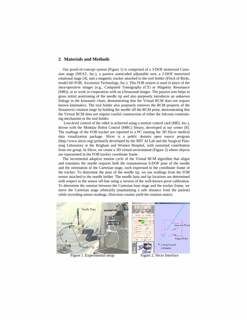
Our proof-of-concept system (Figure 1) is comprised of a 3-DOF motorized Carte-sian stage (NEAT, Inc.), a passive unencoded adjustable arm, a 2-DOF motorized rotational stage [4], and a magnetic tracker attached to the tool holder (Flock of Birds, model 6D FOB, Ascension Technology, Inc.). This FOB system is used in place of the intra-operative imager (e.g., Computed Tomography (CT) or Magnetic Resonance (MR)), or to work in cooperation with an Ultrasound imager. The passive arm helps in gross initial positioning of the needle tip and also purposely introduces an unknown linkage in the kinematic chain, demonstrating that the Virtual RCM does not require known kinematics. The tool holder also purposely removes the RCM property of the Stoianovici rotation stage by holding the needle off the RCM point, demonstrating that the Virtual RCM does not require careful construction of either the fulcrum constrain-ing mechanism or the tool holder.
Low-level control of the robot is achieved using a motion control card (MEI, Inc.), driven with the Modular Robot Control (MRC) library, developed at our center [8]. The readings of the FOB tracker are reported to a PC running the 3D Slicer medical data visualization package. Slicer is a public domain open source program (http://www.slicer.org) primarily developed by the MIT AI Lab and the Surgical Plan-ning Laboratory at the Brigham and Women Hospital, with sustained contribution from our group. In Slicer, we create a 3D virtual environment (Figure 2) where objects are represented in the FOB tracker coordinate frame.
The incremental adaptive motion cycle of the Virtual RCM algorithm that aligns and translates the needle requires both the instantaneous 6-DOF pose of the needle and the orientation of the Cartesian stage, each expressed in the coordinate frame of the tracker. To determine the pose of the needle tip, we use readings from the FOB sensor attached to the needle holder. The needle base and tip locations are determined with respect to the sensor off-line using a version of the well-known pivot calibration. To determine the rotation between the Cartesian base stage and the tracker frame, we move the Cartesian stage arbitrarily (maintaining a safe distance from the patient) while recording sensor readings. Direction cosines yield the rotation matrix.
Figure 1. Experimental setup Figure 2. Slicer Interface
3 Creating the Virtual RCM: A Heuristic Search
As described above, unlike classic RCM robots, the Virtual RCM method does not require (1) the existence of a physically fixed fulcrum point, (2) a priori knowledge of the kinematic chain, or (3) encoding of the joints. This relaxes many requirements previously imposed on RCM needle placement robots. For example, the axes of the Cartesian stage do not need to be orthogonal, the axes of rotation do not need to inter-sect, and kinematically unknown passive linkages are permitted anywhere within the chain. Benefits of this approach include inexpensive and simple robots, elimination of laborious calibration, and rapid prototyping ability without affecting image guidance. The key performance criterion for the Virtual RCM needle placement algorithm, be-sides accuracy and robustness, was fast convergence within very few cycles.
In our Virtual RCM implementation, the yaw and pitch DOF (α and β) are no longer decoupled, and thus cannot be optimized individually. A blind search is not possible for these coupled variables, because it would be impractical to repeatedly rotate the two joints a full 360 degrees until the best alignment is determined from all possible discrete combinations of the two variables. To rapidly optimize these two variables simultaneously, we draw upon techniques developed in the field of AI, such as a heuristic-based Breadth First Search (BFS) or Depth First Search (DFS). We discretize each rotational DOF and partition our search space into two subspaces, one for each angle. A heuristic function guides the search to optimal needle alignment rapidly by intelligently deciding where to search next at each state.
In practical terms, this means that the robot makes incremental motions, and after each it checks to see if the needle is becoming more aligned or less. This tells us which direction is likely to cause better alignment. By continually moving both angles, the robot is able to rapidly home in on the proper alignment.
Selecting a heuristic function that quantifies improvement in needle alignment is not trivial. Good functions should not have local minima that may trap the algorithm before alignment is achieved. Another consideration is that the magnetic tracker (or any other device that can provide the pose of the needle) introduces some uncertainty. Therefore, a good heuristic function must have a low sensitivity to noise. It is also important to conduct an error propagation analysis of candidate heuristic functions. This can be done by applying Equation 1, where z represents a heuristic function. z is a function of measurements, denoted by x and y, subject to sensor uncertainty. The standard deviations (σx and σy) represent the uncertainties in measurement. The total uncertainty of the heuristic function z is then given by:
(1)
This indicates that heuristic functions where sensor readings are multiplied/divided are much more sensitive to sensor noise than heuristics that involve only addition and subtraction.
σz2 =
∂f (x,y)
∂xσ
x2 +
∂f (x,y )
∂yσ
y2
3.1 Two Heuristic Functions: Distance and Cross-Product
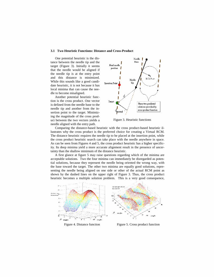
One potential heuristic is the dis-tance between the needle tip and the target (Figure 3). Initially it seems that the needle would be aligned if the needle tip is at the entry point and this distance is minimized. While this sounds like a good candi-date heuristic, it is not because it has local minima that can cause the nee-dle to become misaligned.
Another potential heuristic func-tion is the cross product. One vector is defined from the needle base to the needle tip and another from the in-sertion point to the target. Minimiz-ing the magnitude of the cross prod-uct between the two vectors yields a needle aligned with the entry path.
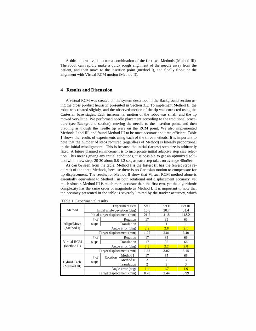
Comparing the distance-based heuristic with the cross product-based heuristic il-lustrates why the cross product is the preferred choice for creating a Virtual RCM. The distance heuristic requires the needle tip to be placed at the insertion point, while the cross product heuristic search can take place with the needle anywhere in space. As can be seen from Figures 4 and 5, the cross product heuristic has a higher specific-ity. Its deep minima yield a more accurate alignment result in the presence of uncer-tainty than the shallow minimum of the distance heuristic.
A first glance at figure 5 may raise questions regarding which of the minima are acceptable solutions. Two the four minima can immediately be disregarded as poten-tial solutions, because they represent the needle being oriented the wrong way, with the base toward the target. The other two minima are equally good solutions, repre-senting the needle being aligned on one side or other of the actual RCM point as shown by the dashed lines on the upper right of Figure 3. Thus, the cross product heuristic becomes a multiple solution problem. This is a very good consequence,
Figure 3. Heuristic functions
Figure 4. Distance function Figure 5. Cross product function
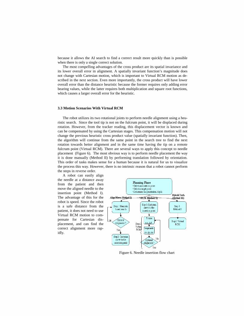
because it allows the AI search to find a correct result more quickly than is possible when there is only a single correct solution.
The most compelling advantages of the cross product are its spatial invariance and its lower overall error in alignment. A spatially invariant function’s magnitude does not change with Cartesian motion, which is important to Virtual RCM motion as de-scribed in the next section. Even more importantly, the cross product will have lower overall error than the distance heuristic because the former requires only adding error bearing values, while the latter requires both multiplication and square root functions, which causes a larger overall error for the heuristic.
3.3 Motion Scenarios With Virtual RCM
The robot utilizes its two rotational joints to perform needle alignment using a heu-ristic search. Since the tool tip is not on the fulcrum point, it will be displaced during rotation. However, from the tracker reading, this displacement vector is known and can be compensated by using the Cartesian stages. This compensation motion will not change the previous heuristic cross product value (spatially invariant function). Then, the algorithm will continue from the same point in the search tree to find the next rotation towards better alignment and in the same time having the tip on a remote fulcrum point (Virtual RCM). There are several ways to apply this concept to needle placement (Figure 6). The most obvious way is to perform needle placement the way it is done manually (Method II) by performing translation followed by orientation. This order of tasks makes sense for a human because it is natural for us to visualize the process this way. However, there is no intrinsic reason that a robot cannot perform the steps in reverse order.
A robot can easily align the needle at a distance away from the patient and then move the aligned needle to the insertion point (Method I). The advantage of this for the robot is speed. Since the robot is a safe distance from the patient, it does not need to use Virtual RCM motion to com-pensate for Cartesian dis-placement, and can find the correct alignment more rap-idly.
Figure 6. Needle insertion flow chart
A third alternative is to use a combination of the first two Methods (Method III). The robot can rapidly make a quick rough alignment of the needle away from the patient, and then move to the insertion point (method I), and finally fine-tune the alignment with Virtual RCM motion (Method II).
4 Results and Discussion
A virtual RCM was created on the system described in the Background section us-ing the cross product heuristic presented in Section 3.1. To implement Method II, the robot was rotated slightly, and the observed motion of the tip was corrected using the Cartesian base stages. Each incremental motion of the robot was small, and the tip moved very little. We performed needle placement according to the traditional proce-dure (see Background section), moving the needle to the insertion point, and then pivoting as though the needle tip were on the RCM point. We also implemented Methods I and III, and found Method III to be most accurate and time efficient. Table 1 shows the results of experiments using each of the three methods. It is important to note that the number of steps required (regardless of Method) is linearly proportional to the initial misalignment. This is because the initial (largest) step size is arbitrarily fixed. A future planned enhancement is to incorporate initial adaptive step size selec-tion. This means giving any initial conditions, it is possible to get an optimized solu-tion within few steps 20-30 about 0.8-1.2 sec, as each step takes on average 40mSec
As can be seen from the table, Method I is the fastest (it has the fewest steps re-quired) of the three Methods, because there is no Cartesian motion to compensate for tip displacement. The results for Method II show that Virtual RCM method alone is essentially equivalent to Method I in both rotational and displacement accuracy, yet much slower. Method III is much more accurate than the first two, yet the algorithmic complexity has the same order of magnitude as Method I. It is important to note that the accuracy presented in the table is severely limited by the tracker accuracy, which
Table 1. Experimental results Experiment Sets Set I Set II Set III
Initial angle deviation (deg) 15.6 28.7 51.4 Method Initial target displacement (mm) 21.2 41.8 118.2
Rotation 17 35 66 # of steps Translation 1 1 1
Angle error (deg) 2.2 2.8 2.1 Align/Move (Method I)
Target displacement (mm) 1.05 2.81 3.40 Rotation 17 35 66 # of
steps Translation 17 35 66 Angle error (deg) 2.8 2.2 2.8
Virtual RCM (Method II)
Target displacement (mm) 1.68 3.02 5.15 Method I 17 35 66 Rotation Method II 2 2 3
# of steps
Translation 2 2 3 Angle error (deg) 1.4 1.7 1.9
Hybrid Tech. (Method III)
Target displacement (mm) 0.78 2.44 3.99

is reported by the manufacturer as 2.54 mm RMS (this is a first-generation FOB tracker).
5 Future Work
A future goal is to replace the magnetic tracker with a CT scanner. We will gather the pose of the needle tip directly from the CT images using the method described in [3]. Our ultimate goal is to accurately place needles using inexpensive, uncalibrated, and unencoded robots in intra-operative imagers (CT, MRI, and X-ray fluoroscopy), with the use of purely image-based spatial registration of the tool holder alone. We also hope to perform experiments under ultrasound guidance, where we will retain the external tracker. In terms of algorithmic enhancements, we will incorporate target uncertainty into our model, in order to account for motion artifacts.
Acknowledgements
The authors acknowledge the support of the NSF under the Engineering Research Center grant #EEC-9731478 and the National Defense Science and Engineering Graduate fellowship program, which supports Robert Webster. We also wish to ac-knowledge Dr. Dan Stoianovici for access to and repair of the RCM mechanism.
References
1. Hutchinson S, Hager, GD, Corke, P: A Tutorial Introduction to Visual Servo Control. IEEE Transactions on Robotics and Automation. 1996; 12(5):651-670.
2. Khatib O: A Unified Approach for Motion and Force Control of Robot Manipulators: The Operational Space Formulation. IEEE Journal of Robotics and Automation, 1987 Feb; RA-3(1):43-53.
3. Lee S, Fichtinger G, Chirikjian GS: Novel Algorithms for Robust Registration of Fi-ducials in CT and MRI. Journal of Medical Physics, Vol. 29, No. 8, pp. 1881-1891, 2002
4. Stoianovici D: URobotics - Urology Robotics at Johns Hopkins. Comp Aid Surg, 2001, (6):360-369
5. Taylor RH, Funda J, Eldridge B, Gruben K, LaRose D, Gomory S, Talamini M, Kavoussi LA, and Anderson JH: A Telerobotic Assistant for Laparoscopic Surgery. IEEE EMBS Magazine Special Issue on Robotics in Surgery. 1995. pp. 279-291
6. Margrit Betke, supervised by Ronald Rivest: Learning and Vision Algorithms for Robot Navigation. Ph.D. dissertation in EECS dept. at the MIT June 1995.
7. John J. Craig: Introduction to Robotics Mechanics and Control. 3rd Edition. Addison Wesley, Reading, MA, 1992.
8. http://cisstweb.cs.jhu.edu/resources/software/mrc/


![[Clement Hal] Clement, Hal - Needle 1 - Needle](https://static.fdocuments.in/doc/165x107/577cb1001a28aba7118b67ae/clement-hal-clement-hal-needle-1-needle.jpg)