Virtual Reality Modeling Electrical and Computer Engineering Dept. from
59
Virtual Reality Modeling Virtual Reality Modeling Electrical and Computer Engineering Dept. from http:// www.okino.com /
-
Upload
jessie-palmer -
Category
Documents
-
view
220 -
download
3
Transcript of Virtual Reality Modeling Electrical and Computer Engineering Dept. from

Virtual Reality ModelingVirtual Reality Modeling
Electrical and Computer Engineering Dept.
from http://www.okino.com/

System architecture
ModelingModeling&&
VR ToolkitsVR Toolkits

The VR object modeling cycle:The VR object modeling cycle:Geometric modeling; Kinematics modeling; Physical modeling; Object behavior (intelligent agents); Model management.

The VR geometric modeling: The VR geometric modeling:
Object surface shape: polygonal meshes (vast majority); splines (for curved surfaces);
Object appearance:• lighting (shading) texture mapping

The surface polygonal (triangle) meshThe surface polygonal (triangle) mesh
Shared vertexShared vertex
Non-shared vertexNon-shared vertex
(X(X00,Y,Y00,Z,Z00))
(X(X11,Y,Y11,Z,Z11))
(X(X22,Y,Y22,Z,Z22))
(X(X33,Y,Y33,Z,Z33))
(X(X44,Y,Y44,Z,Z44))
(X(X55,Y,Y55,Z,Z55))
Triangle meshes are preferred since they are memoryand computationally efficient (shared vertices)

Object spline-based shape: Object spline-based shape: Another way of representing virtual objects; Functions are of higher degree than linear functions describing a polygon – use less storage and provide increased surface smoothness. Parametric splines are represented by points x(t), y(t), z(t), t=[0,1] and a, b, c are constant coefficients.

Object spline-based shape: Object spline-based shape:
Parametric surfaces are extension of parametric splines with point coordinates given by x(s,t), y(s,t), z(s,t), with s=[0,1] and t=[0,1].
β-Splines are controlled indirectly through four control points (more inphysical modeling section)

Object polygonal shape: Object polygonal shape: Can be programmed from scratch using OpenGL or other toolkit editor; it is tedious and requires skill; Can be obtained from CAD files; Can be created using a 3-D digitizer (stylus), or a 3-D scanner (tracker, cameras and laser); Can be purchased from existing online databases (Viewpoint database). Files have vertex location and connectivity information, but are static.

Geometric ModelingGeometric Modeling
Venus de Milo created Venus de Milo created using the HyperSpace using the HyperSpace 3D digitizer, 4200 textured 3D digitizer, 4200 textured polygons using NuGraphpolygons using NuGraphtoolkit toolkit

Polhemus 3-D scanners: Polhemus 3-D scanners: Eliminate direct contact with object. uses two cameras, a laser, and magnetic trackers (if movable objects are scanned) Scanning resolution 0.5 mm at 200 mm range; Scanning speed is 50 lines/sec; Range is 75-680 mm scanner-object range.

Geometric ModelingGeometric Modeling
Polhemus FastScan 3D scanner (can scan objects up to 3 m long).Polhemus FastScan 3D scanner (can scan objects up to 3 m long).

DeltaSphere 3000 3D scannerDeltaSphere 3000 3D scanner
www.3rdtech.com
Large models need large-volumeScanners; The 3rdTech scanners use time-of-flightmodulated laser beam to determine position.Features:
Scanning range up to 40 ft; Resolution 0.01 in; accuracy 0.3 in; scan density of up to 7200 samples/360º; complete scene scanning in 10 – 30 minutes (scene has to be static); optional digital color camera (2008x1504 resolution) to add color to models. Requires a second scan, and reduces elevation to 77º.
360360º horizontalº horizontal
150150º elevationº elevation
electrical motor electrical motor and CPU and CPU

DeltaSphere 3000 3D scannerDeltaSphere 3000 3D scanner
www.3rdtech.com
Polhemus scannerPolhemus scanner
Feature Polhemus scanner DeltaSphere scanner
Range 0.56 m 14.6 m
Resolution 0.5 mm @ 0.2 m 0.25 mm
Control manual automatic
Speed 50 lines/sec 25,000 samples/sec

Conversion of scanner data: Conversion of scanner data: Scanners produce a dense “cloud” of vertices (x,y,z). Using such packages as Wrap (www.geomagic.com) the point data are transformed into surface data (including editing and decimation)
Point cloudPoint cloudfrom scannerfrom scanner
Polygonal mesh Polygonal mesh after decimationafter decimation

PolygonalPolygonal surfacesurface
NURBS surface NURBS surface NURBS (non-uniformNURBS (non-uniformrational rational β-splines) patchesβ-splines) patches

Higher resolution model > 20,000 polygons.
Low res. Model – 600 polygons
Geometric Modeling – using online databasesGeometric Modeling – using online databases

Object Visual Appearance Object Visual Appearance
Scene illumination (local or global); Texture mapping; Multi-textures Use of textures to do illumination in the rasterizing
stage of the pipeline

Scene illumination Scene illumination Local methods (Flat shaded, Gouraud shaded, Phong shaded) treat objects in isolation. They are computationally faster than global illumination methods;
Global illumination treats the influence of one object on another object’s appearance. It is more demanding from a computation point of view but produces more realistic scenes.

Phong shading modelPhong shading model
Flat shading modelFlat shading model
Ip = Ib – (Ib- Ia) xb-xp
xb-xa
Gouraud shading modelGouraud shading model
Local illumination methodsLocal illumination methods

Flat shaded Flat shaded Utah Teapot Utah Teapot
Phong shaded Phong shaded Utah Teapot Utah Teapot

Global scene illumination Global scene illumination The inter-reflections and shadows cast by objects on each other.

Radiosity illumination Radiosity illumination Results in a more realistic looking scene
Without radiosity With radiosity

Texture mapping Texture mapping It is done in the rasterizer phase of the graphics
pipeline, by mapping assigning texture space
coordinates to polygon vertices (or splines),
then mapping these to pixel coordinates; Texture increase scene realism; Texture provide better 3-D spatial cues (they are
perspective transformed); They reduce the number of polygons in the scene –
increased frame rate (example – tree models).

Textured room image for increased realismTextured room image for increased realism
from http://www.okino.com/

VR Modeling
ApplicationApplication GeometryGeometry
ComputeComputeObject spaceObject space
LocationLocation
Use projectorUse projectorFunction for Function for
Parameter spaceParameter space
CorresponderCorresponderFunction toFunction toFind pixelFind pixel
Apply valueApply valueTransform Transform
functionfunction
Modify Modify Illumination Illumination
equationequation
The Texturing Functional Sub-StagesThe Texturing Functional Sub-Stages
RasterizerRasterizer

How to create textures: How to create textures: Models are available on line in texture
“libraries” of cars, people, construction materials, etc.
Custom textures from scanned photographs or Using an interactive paint program to create bitmaps

Texture mappingTexture mapping
Object surfaceObject surface
Texture spaceTexture space
Screen spaceScreen space
256x256 texture
[0,1]
[0,1]
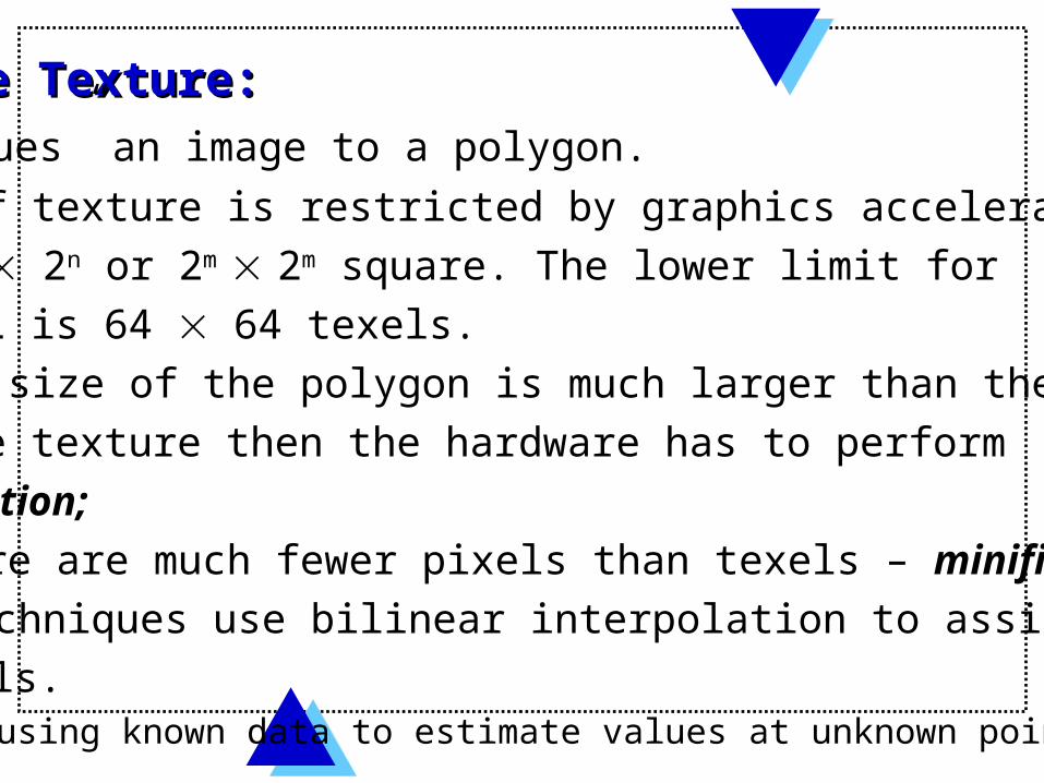
Image Texture: Image Texture: It “glues” an image to a polygon. Size of texture is restricted by graphics accelerators
to 2m 2n or 2m 2m square. The lower limit for
OpenGL is 64 64 texels. If the size of the polygon is much larger than the size
of the texture then the hardware has to perform
Magnification; If there are much fewer pixels than texels – minification; Both techniques use bilinear interpolation to assign colors
to pixels. works by using known data to estimate values at unknown points.

Texture minification: Texture minification:
Texture
Pixel
Uses various “filters” to approximate the color of the pixel: nearest neighbor (to texel closest to the pixel center is selected, bilinear interpolation, etc.)

Multi-texturing: Multi-texturing: Several texels can be overlaid on one pixel; A texture blending cascade is made up of a series of texture stages
(from “Real Time Rendering”)
Interpolated Interpolated vertex valuesvertex values
Texture Texture
value 0 value 0
Stage 0 Stage 1 Stage 2
Texture Texture
value 1 value 1
Texture Texture
value 2 value 2
Polygon/Polygon/
Image buffer Image buffer

Allow more complex texturesAllow more complex textures
TransparencyTransparency texturetexture
Normal Normal texturetexture
BackgroundBackground texturetexture
Reflectivity Reflectivity texturetexture

Multi-texturing for bump mapping: Multi-texturing for bump mapping: Lighting effects caused by irregularities on object
surface are simulated through “bump mapping”; This encodes surface irregularities as textures; No change in model geometry. No added
computations at the geometry stage;

Multi-texturing for lighting: Multi-texturing for lighting: Several texels can be overlaid on one pixel; One application in more realistic lighting; Polygonal lighting is real-time but requires lots of
polygons (triangles) for realistic appearance
Vertex lighting of low polygoncount surface – lights are diffuse –tessellated.
Vertex lighting of high polygoncount surface – lights have realisticappearance. High computation load
(from NVIDIA technical brief)

Multi-texturing (texture blending): Multi-texturing (texture blending): Realistic-looking lighting can be done with
2-D textures called “light maps”; Not applicable to real-time (need to be recomputed
when object moves)
Standard lighting map 2-D texture
Light map texture overlaid on top of wall texture. Realistic and low polygon count. Not real-time!
(from NVIDIA technical brief)

KINEMATICS MODELING: KINEMATICS MODELING:
Homogeneous transformation matrices;Object hierarchies; Viewing the 3-D world.

Homogeneous Transformations: Homogeneous Transformations: Homogeneous system of coordinates is a
right-hand Cartesian system of coordinates with
orthonormal unit vector triads; Such (i, j, k) triads have the property that their
norms |i|= |j| = |k| = 1 and their dot product is
i • j = i • k = j • k = 0; A · B = A.x * B.x + A.y * B.y + A.z * B.z
Suppose that a = 3i + 5j - 2k and b = 2i - 2j - 2k.
a.b = (3 x 2) + (5 x -2) + (-2 x -2) = 6 - 10 + 4 = 0
Homogeneous transformation matrices relate two
such systems through a 4 4 matrix.

Homogeneous Transformations: Homogeneous Transformations: Have the general format:
T A B = [ ] R3x3 P3x1
0 0 0 1
where R3x3 is the rotation submatrix expressing the orientation
of the system of coordinates B vs. system of coordinates A;
P3x1 is the position vector of the origin of system B
vs. the origin of system of coordinates A.

Homogeneous Transformations:Homogeneous Transformations:
Have many advantages: treat object translation and rotation mathematically
in the same way; are easily invertible;
T B A = ( T A B ) -1 =[ ] RT -RT P
0 0 0 1

Object Position/Orientation (static): Object Position/Orientation (static): given by homogeneous transformation matrix
that relates the object system of coordinates to
world system of coordinates.
T W 1 = [ ]iw1 jw1 kw1 P1
0 0 0 1
where iw1 , jw1 , kw1 are
3 1 vectors projecting the object unit vectors into word system of coordinates

Object Position/Orientation (moving): Object Position/Orientation (moving): If the virtual object moves, then the
transformation matrix becomes a function of time
T W 1 (t) = [ ]iw1 (t) jw1(t) kw1(t) P1 (t)0 0 0 1
The position of an object vertex Vi in word coordinates versus its position in object coordinates
Vi(W) (t) = T W 1 (t) Vi
(object)

If the aligned virtual object translates, all vertices translate
VVii(W)(W) (t)(t) = = VVi i
(object)(object) [[ ]]1 0 0 p1 0 0 p1x 1x (t)(t)
0 1 0 p0 1 0 p1y 1y (t)(t)
0 0 1 p0 0 1 p1z 1z (t)(t)
0 0 0 10 0 0 1

If the virtual object translates back to its initial position, all its vertices translate by an equal but negative amount.
VVii(W)(W) (t)(t) = = VVi i
(object)(object) [[ ]]1 0 0 -p1 0 0 -p1x 1x (t)(t)
0 1 0 -p0 1 0 -p1y 1y (t)(t)
0 0 1 -p0 0 1 -p1z 1z (t)(t)
0 0 0 10 0 0 1

If the virtual object needs to be scaled, it is translated to origin, scaled, then translated to back
VVii(W)(W) (t)(t) = = T T W W 2 2 T T W W 1 1VVi i
(object)(object) [[ ]]ssii 0 0 0 0 0 0
0 s0 sjj 0 0 0 0
0 0 s0 0 sk k 0 0
0 0 0 1 0 0 0 1

VR Kinematics ModelingVR Kinematics Modeling
a) b)
Model hierarchy: a) static model (Viewpoint Datalabs); b) segmented model.

Object Hierarchies: Object Hierarchies: Allows models to be partitioned into a hierarchy,
and become dynamic; Segments are either parents (higher level object)
or children (lower level objects). The motion of a parent is replicated by its
children but not the other way around. Example – the virtual human and the virtual
hand; At the top of the hierarchy is the “world global
transformation” that determines the view to the scene.

Clipping Transformation: Clipping Transformation: Since the fulcrum maps to the unit cube, only objects inside it will be rendered. Some objects are partly inside the unit cube (ex. the line and the rectangle). Then they need to be “clipped”. The vertex VV1 1 is replaced by new one at the intersection between the line and the viewing cone, etc.
ZZ
XX
Unit cubeUnit cube
ZZ
XX
VV11
VV22
VV33
VV11
VV22
VV33
Scene clippingScene clipping

Screen Mapping (Viewport Transformation): Screen Mapping (Viewport Transformation): The scene is rendered into a window with corners (x1,y1), (x2,y2)
Screen mapping is a translation followed by a scaling that affects the x and y coordinates of the primitives (objects), but not their z coordinates. Screen coordinates plus z [-1,1] are passed to the
rasterizer stage of the pipeline.
ZZ
XX
VV11
VV22
VV33
Screen mappingScreen mapping
(x1,y1)(x1,y1)
(x2,y2)(x2,y2)

from (Burdea 1996)
The VR physical modeling:The VR physical modeling:

Uses bounding box collision detection for fast response; Two types of bounding boxes, with fixed size or variable size (depending on enclosed object orientation). Fixed size is computationally faster, but less precise
Collision detection:Collision detection:
Variable size Bounding BoxVariable size Bounding Box Fixed size Bounding BoxFixed size Bounding Box

Collision DetectionCollision Detection

For more precise detection, we use a two-stage collision detection: an approximate (bounding box ) stage, followed by a slower exact collision detection stage.
Two-stage collision detection:Two-stage collision detection:
Bounding Box PruningBounding Box Pruning multi-body pairsmulti-body pairs
Pair-wise exactPair-wise exactCollision DetectionCollision Detection
Simulation Simulation
Collision responseCollision response
yes
yes
no

Agent behavior: Agent behavior: A behavior model composed of perception, emotions,
behavior, and actions; Perception (through virtual sensors) makes the agent
aware of his surroundings.
PerceptionPerception EmotionsEmotions
BehaviorBehavior
ActionsActions
Virtual worldVirtual world

Reflex behavior: Reflex behavior: A direct link between perception and actions (following
behavior rules (“cells”); Does not involve emotions.
PerceptionPerception EmotionsEmotions
BehaviorBehavior
ActionsActions

Object behaviorObject behavior
Another example of reflex behavior – “Dexter” at MIT [Johnson, 1991]: Hand shake, followed by head turn
Autonomous virtual humanAutonomous virtual human
User-controlled hand avatarUser-controlled hand avatar

Agent behavior - Agent behavior - avatarsavatars
If user maps to a full-body avatar, then virtual human agents react through body expression recognition: example dance. Swiss Institute of Technology, 1999(credit Daniel Thalmann)
Autonomous virtual humanAutonomous virtual humanUser-controlled hand avatarUser-controlled hand avatar

Emotional behavior: Emotional behavior: A subjective strong feeling (anger, fear) following perception; Two different agents can have different emotions to the same perception, thus they can have different actions.
Virtual worldVirtual world
Emotions 2Emotions 2 PerceptionPerception
BehaviorBehavior
Actions 2Actions 2
Perception Perception Emotions 1Emotions 1
BehaviorBehavior
Actions 1Actions 1

Crowds behaviorCrowds behavior
(Thalmann et al., 2000)
Crowd behavior emphasizes group (rather than individual) actions; Crowds behavior is defined explicitly by the user; Or the behaviors specified by rules and other complex methods (including memory).
Political demonstrationPolitical demonstration
Guided crowdGuided crowdUser needs to specifyIntermediate path points
Autonomous crowdAutonomous crowdGroup perceives info onits environment and decides a path to follow to reach the goalVC 5.3

MODEL MANAGEMENT MODEL MANAGEMENT It is necessary to maintain interactivity and
constant frame rates when rendering complex
models. Technique used is Level of detail segmentation;

Level of detail segmentation: Level of detail segmentation: Level of detail (LOD) relates to the number of polygons
on the object’s surface. Even if the object has high
complexity, its detail may not be visible if the object is
too far from the virtual camera (observer).
Tree with 27,000 polygons Tree with 27,000 polygons
Tree with 27,000 polygons Tree with 27,000 polygons (details are not perceived)(details are not perceived)