VIRGINIA DEPARTMENT OF MINES, MINERALS & … · 3 Explosive safety is developed through the proper...
73
VIRGINIA DEPARTMENT OF MINES, MINERALS & ENERGY DIVISION OF MINES SHOT FIRER CERTIFICATION STUDY GUIDE 2010 Copyright 1997 Commonwealth of Virginia Commonwealth of Virginia Department of Mines, Minerals, and Energy Division of Mines P.O. Drawer 900 Big Stone Gap, VA 24219 (276) 523-8100
Transcript of VIRGINIA DEPARTMENT OF MINES, MINERALS & … · 3 Explosive safety is developed through the proper...

VIRGINIA DEPARTMENT OF MINES, MINERALS & ENERGY
DIVISION OF MINES
SHOT FIRER
CERTIFICATION STUDY GUIDE
2010
Copyright 1997 Commonwealth of Virginia Commonwealth of Virginia
Department of Mines, Minerals, and Energy Division of Mines P.O. Drawer 900
Big Stone Gap, VA 24219
(276) 523-8100
1
UNDERGROUND SHOT FIRER STUDY GUIDE
TABLE OF CONTENTS PAGE
1. Introduction......................................................................................................................................2
2. State Law .........................................................................................................................................5
3. MSHA Law....................................................................................................................................10
4. ATF Permits...................................................................................................................................17
5. Permissible Explosives ..................................................................................................................18
6. Surface Storage of Explosives and Detonators ..............................................................................21
7. Underground Storage of Explosives and Detonators.....................................................................23
8. Underground Transportation of Explosives and Detonators .........................................................25
9. Coal Dust .......................................................................................................................................27
10. Shooting Cut Coal..........................................................................................................................28
11. Shooting off the Solid ....................................................................................................................29
12. Drilling...........................................................................................................................................30
13. Loading ..........................................................................................................................................33
14. Stemming .......................................................................................................................................35
15. Wiring ...........................................................................................................................................36
16. Firing..............................................................................................................................................43
17. Post Blast Inspection......................................................................................................................44
18. Misfires ..........................................................................................................................................45
19. Good Blasting Practices.................................................................................................................51
20. Blasting Instruments ......................................................................................................................55
21. Overcast Blasting ...........................................................................................................................57
22. Practicals .......................................................................................................................................60
2
SHOT FIRER’S UNDERGROUND
STUDY GUIDE
INTRODUCTION
This guide was written to assist in providing the knowledge and safety practices necessary to perform the duties of an underground shot firer. As underground shot firer shall have a thorough knowledge of the theory, storage, transportation, and use of explosives.
An applicant for an underground shot firer must meet the following requirements: Two years mining experience underground, with one year of the two years shall be handling and using explosives underground under the direction of a certified underground shot firer or appropriately related work experience approved by the Chief of the Division of Mines. Hold a General Miner Certification. Current first aid training (MSHA first aid 5000-23 acceptable)
The use of explosives in underground coal mines continues to present a potentially serious risk of injury and death of miners. The prevention of explosive accidents depends, to a large extent, on two factors: (1) the knowledge and experience of persons in the mine responsible for the use of explosives and (2) well defined, safety precautions to guide mine operators and miners in the safe conduct of blasting operations.
The prevention of explosive accidents depends on careful planning and faithful observance of proper blasting practices. The slightest abuse or misdirection of explosives may either kill or cause serious injury, to miners.
Failure of miners to follow safe blasting practices has contributed significantly to explosive accidents.
The miner most frequently injured in explosive accidents is the person firing the shot. Two general statements should be acknowledged and understood about the safety and use of explosives: 1. A shot firer’s most important responsibility is safety. 2. The safety of every blasting operation depends on its people.
A shot firer must posses the proper attitude to become a safe and efficient blaster. The safety of every blasting operation is also dependent upon the attitude, knowledge, training, and
experience of other miners who handle explosives. Miners designated to handle explosives must have intelligence, common sense, trained in the use of
explosives and they must know what is and is not safe. Explosive safety is a habit that can only be developed through constant training repetition of safe
working habits.

3
Explosive safety is developed through the proper individual attitude and the proper training to transport, store, handle and use explosives in a safe manner.
Safety is the individual responsibility of every miner for his personal safety and the safety of other
miners.

4
DEPARTMENT OF MINES, MINERALS AND ENERGY
DIVISION OF MINES
DISCLAIMER
Article 3 of the Coal Mine Safety Laws of Virginia establishes requirements for certification of coal mine workers. The certification requirements are included in §45.1-161.24. through §45.1-161.41. in which the Board of Coal Mining Examiners is established for the purpose of administering the certification program. The Board has promulgated certification regulations 4 VAC 25-20, which set the minimum standards and procedures required for Virginia coal miner examinations and certifications. The Virginia Department of Mines, Minerals and Energy, Division of Mines developed this study guide to better train coal miners throughout the mining industry. The study guide material should be used to assist with the knowledge necessary for coal mining certifications. The material is not all-inclusive and should be used only as an aide in obtaining knowledge of the mining practices, conditions, laws and regulations. This material is based upon the Coal Mining Safety Laws of Virginia, Safety and Health Regulations for Coal Mines in Virginia, Title 30 Code of Federal Regulations (30 CFR), State and Federal Program Policy Manuals and other available publications. Nothing herein should be construed as recommending any manufacturer’s products.
The study guide and materials are available at the Department of Mines, Minerals and Energy. Any questions concerning the study guide should be addressed to the Regulatory Boards Administrator at the Big Stone Gap Office.

5
Coal Mine Safety Laws of Virginia
45.1-161.126. Surface storage of explosives
A. Separate surface magazines shall be provided for the storage of explosives and detonators. B. Surface magazines for storing and distributing explosives in amounts exceeding 150 pounds shall be:
1. Reasonably bulletproof and constructed of incombustible material or covered with fire-resistive material. The roofs of magazines so located that it is impossible to fire bullets directly through the roof from the ground need not be bulletproof, but where it is possible to fire bullets directly through them, roofs shall be made bullet-resistant by material construction, or by a ceiling that forms a tray containing not less than a four-inch thickness of sand, or by other methods;
2. Provided with doors constructed of three-eighth inch steel plate lined with a two-inch thickness of wood, or the equivalent;
3. Provided with dry floors made of wood or other nonsparking material and have no metal exposed inside the magazine;
4. Provided with suitable warning signs so located that a bullet passing directly through the face of a sign will not strike the magazine;
5. Provided with properly screened ventilators 6. Equipped with no openings except for entrance and ventilation; 7. Kept locked securely when unattended; and 8. Electrically bonded and grounded if constructed of metal.
C. Surface magazines for storing detonators need not be bulletproof, but they shall conform to the other provisions of subsection B regarding the storage of explosives.
D. Explosives in amounts of 150 pounds or less or 5,000 detonators or less shall be stored in accordance with preceding standards or in separate locked box-type magazines. Box-type magazines may also be used as distributing magazines when quantities do not exceed those mentioned. Box-type magazines shall be constructed strongly of two-inch hardwood or the equivalent. Metal magazines shall be lined with nonsparking material. No magazine shall be placed in a building containing oil, grease, gasoline, wastepaper or other highly flammable material; nor shall a magazine be placed within 20 feet of a stove, furnace, open fire or flame.
E. Magazines shall be located not less than 300 feet from any mine opening. However, in the event that a magazine cannot be practicably located at such a distance, a magazine may be located less than 300 feet from any mine opening, if it is sufficiently barricaded and approved by the Chief. Unless approved by the Chief, magazines shall not be located closer to occupied buildings, public roads, or passenger railways than allowed in the "American Table of Distances for Storage of Explosive Materials."
F. The supply kept in distribution magazines shall be limited to approximately a 48-hour supply, and such supplies of explosives and detonators may be distributed from the same magazine, if separated by at least a four-inch substantially fastened hardwood partition or equivalent barrier.
G. The area surrounding magazines for not less than 25 feet in all directions shall be kept free of rubbish, dry grass or other materials of a combustible nature.
H. If the explosives magazine is illuminated electrically, vapor-proof lamps shall be installed and wired so as to present minimum fire and contact hazards.
I. Only nonmetallic tools shall be used for opening wooden explosives containers. Extraneous materials shall not be stored with explosives or detonators in an explosives magazine.

6
45.1-161.127. Underground transportation of explosives
A. Explosives or detonators carried anywhere underground by any person shall be in individual containers. Such containers shall be constructed substantially of nonconductive material, maintained in good condition, and kept closed.
B. Explosives or detonators transported underground in cars moved by means of a locomotive or rope, or in shuttle cars, shall be in substantially covered cars or in special substantially covered containers used specifically for transporting detonators or explosives, and only under the following conditions: 1. The bodies and covers of such cars and containers shall be constructed or lined with
nonconductive material; 2. If explosives and detonators are hauled in the same explosive car or in the same special
container, they shall be separated by at least a four-inch substantially fastened hardwood partition or equivalent barrier;
3. Explosives, detonators, or other blasting devices shall not be transported on the same trip with miners;
4. When explosives or detonators are transported in special cars or containers in cars, they shall be hauled in special trips not connected to any other trip; however, this shall not prohibit the use of such additional cars as needed to lower a rope trip, or to haul supplies including timbers. Materials so transported shall not project above the top of the car. In no case shall flammable materials such as oil or grease be hauled on the same trip with explosives; and
5. Explosives or detonators shall not be hauled into or out of a mine within five minutes preceding or following a man-trip or any other trip. If traveling against the air current, the man-trip shall precede the explosives trip; if traveling with the air current, the man-trip shall follow the explosives trip.
C. In low coal seams where it is impractical to comply with subsection B, explosives may be transported in the original and unopened case, or in suitable individual containers, to the underground distribution magazine.
D. Explosives and detonators shall be transported underground by belt only under the following conditions: 1. They shall be transported in the original and unopened case, in special closed cases constructed
of nonconductive material, or in suitable individual containers; 2. Clearance requirements shall be the same as those for transporting miners on belts; 3. Suitable loading and unloading stations shall be provided; and 4. Stop controls shall be provided at loading and unloading points, and an authorized person shall
supervise the loading and unloading of explosives and detonators. 5. Neither explosives nor detonators shall be transported on flight or shaking conveyors, scrapers,
mechanical loading machines, locomotives, cutting machines, drill trucks, or any self-propelled mobile equipment; however, this shall not prohibit the transportation of explosives or detonators in special closed containers in shuttle cars or in equipment designed especially to transport such explosives or detonators.
45.1-161.128. Underground storage of explosives
A. When supplies of explosives and detonators for use in one or more sections are stored underground, they shall be kept in section boxes or magazines of substantial construction with no metal exposed
7
on the inside. Such boxes or magazines shall be located at least twenty-five feet from roadways and power wires, and in a reasonably dry, well rock-dusted location protected from falls of roof. In pitching beds, where it is not possible to comply with the location requirement, such boxes shall be placed in niches cut into the solid coal or rock.
B. When explosives or detonators are stored in the section, they shall be kept in separate boxes or magazines not less than twelve feet apart if feasible; if kept in the same box or magazine, they shall be separated by at least a four-inch substantially fastened hardwood partition or the equivalent. Not more than a forty-eight-hour supply of explosives or detonators shall be stored underground in such boxes or magazines.
C. Explosives and detonators, kept near the face for the use of workmen, shall be kept in separate individual closed containers, in niches in the rib, not less than twelve feet apart, at least fifty feet from the working place and out of the line of blast. Such containers shall be constructed of substantial material and maintained electrically nonconductive. Where it is physically impracticable to comply with such distance requirements, the explosives and detonator containers shall be stored in the safest available place not less than fifteen feet from any pipe, rail, conveyor, haulage road, or power line, not less than twelve feet apart, and at least fifty feet from the working face and out of line of blast.
D. Explosives and detonators shall be kept in their containers until immediately before use at the working faces.
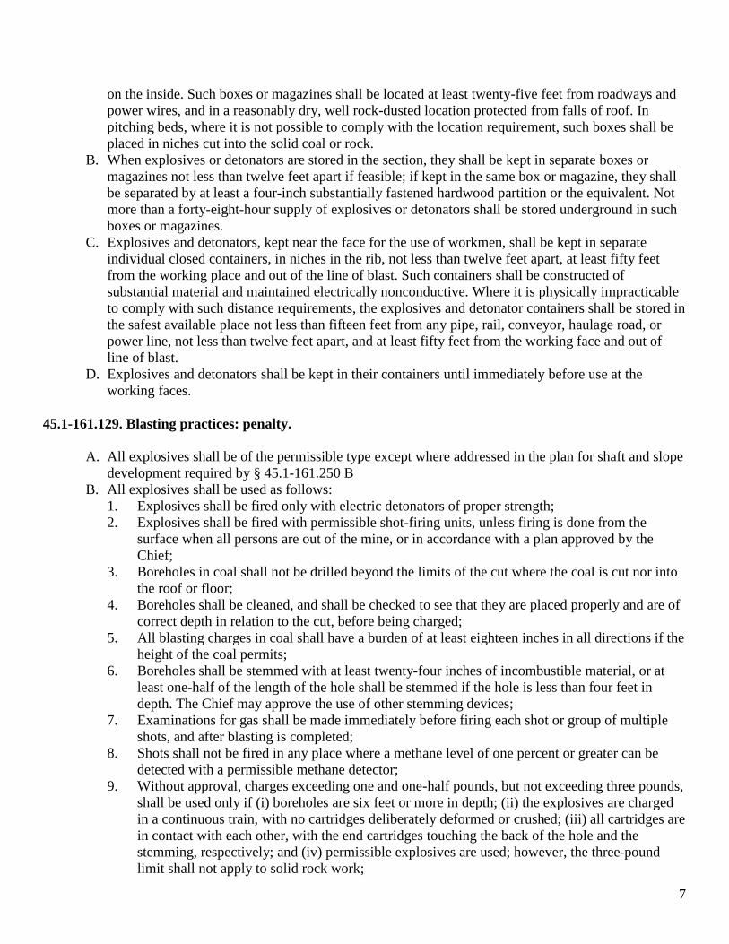
45.1-161.129. Blasting practices: penalty.
A. All explosives shall be of the permissible type except where addressed in the plan for shaft and slope development required by § 45.1-161.250 B
B. All explosives shall be used as follows: 1. Explosives shall be fired only with electric detonators of proper strength; 2. Explosives shall be fired with permissible shot-firing units, unless firing is done from the
surface when all persons are out of the mine, or in accordance with a plan approved by the Chief;
3. Boreholes in coal shall not be drilled beyond the limits of the cut where the coal is cut nor into the roof or floor;
4. Boreholes shall be cleaned, and shall be checked to see that they are placed properly and are of correct depth in relation to the cut, before being charged;
5. All blasting charges in coal shall have a burden of at least eighteen inches in all directions if the height of the coal permits;
6. Boreholes shall be stemmed with at least twenty-four inches of incombustible material, or at least one-half of the length of the hole shall be stemmed if the hole is less than four feet in depth. The Chief may approve the use of other stemming devices;
7. Examinations for gas shall be made immediately before firing each shot or group of multiple shots, and after blasting is completed;
8. Shots shall not be fired in any place where a methane level of one percent or greater can be detected with a permissible methane detector;
9. Without approval, charges exceeding one and one-half pounds, but not exceeding three pounds, shall be used only if (i) boreholes are six feet or more in depth; (ii) the explosives are charged in a continuous train, with no cartridges deliberately deformed or crushed; (iii) all cartridges are in contact with each other, with the end cartridges touching the back of the hole and the stemming, respectively; and (iv) permissible explosives are used; however, the three-pound limit shall not apply to solid rock work;

8
10. Any solid shooting shall be done in compliance with conditions prescribed by the Chief; 11. Shots shall be fired by a certified underground shot firer; 12. Boreholes shall not be charged while any other work is being done at the face, and the shot or
shots shall be fired before any other work is done in the zone of danger from blasting except that which is necessary to safeguard the miners;
13. Only nonmetallic tamping bars, including a nonmetallic tamping bar with a nonsparking metallic scraper on one end, shall be used for charging and tamping boreholes;
14. The leg wires of electric detonators shall be kept shunted until ready to connect to the firing cable;
15. The roof and faces of working places shall be tested before and after firing each shot or group of multiple shots;
16. Ample warning shall be given before shots are fired, and care shall be taken to ascertain that all miners are in the clear;
17. All miners shall be removed from the working place and the immediately adjoining working place or places to a distance of at least 100 feet and accounted for before shots are fired;
18. Mixed types or brands of explosives shall not be charged or fired in any borehole; 19. Adobe (mudcap) or other open, unconfined shots shall not be fired in any mine except those
types approved by the Mine Safety and Health Administration and the Chief; 20. Power wires and cables that could contact blasting cables or leg wires shall be de-energized
during charging and firing; 21. Firing shots from a properly installed and protected blasting circuit may be permitted by the
Chief; 22. No miner shall return, or shall be allowed to return, to the working place after the firing of any
shot or shots until the smoke has reasonably cleared away. 23. Before returning to work and beginning to load coal, slate or refuse, a miner shall make a
careful examination of the condition of the roof and do what is necessary to make the working place safe; and
24. An examination for fire shall be made of the working area after any blasting.
C. It shall be unlawful for an operator, his agent, or mine foreman to cause or permit any solid shooting to be done without first having obtained a written permit from the Chief. It shall be unlawful for any miner to shoot coal from the solid without first obtaining permission to do so from the operator, his agent, or mine foreman. A violation of this subsection is a Class 1 misdemeanor.
45.1-161.130. Blasting cables. – Blasting cables shall be:
1. Well insulated and as long as may be necessary to permit the shot firer to get in a safe place around a corner;
2. Short-circuited at the battery end until ready to attach to the blasting unit; 3. Staggered as to length or the ends kept well separated when attached to the detonator leg wires; and 4. Kept clear of power wires and all other possible sources of active or stray electric currents.
45.1-161.131. Misfires.
A. Where misfires occur with electric detonators, a waiting period of at least fifteen minutes shall elapse before a miner shall be allowed to return to the shot area. After such failure, the blasting cable shall be disconnected from the source of power and the battery ends short-circuited before electric connections are examined.

9
B. Explosives shall be removed by firing a separate charge at least two feet away from, and parallel to, the misfired charge or by washing the stemming and the charge from the borehole with water, or by inserting and firing a new primer after the stemming has been washed out.
C. A very careful search of the working place, and, if necessary, of the coal shall be conducted after the coal reaches the tipple after blasting a misfired hole to recover any undetonated explosive.
D. The handling of a misfired shot shall be directly supervised by the mine foreman or a certified person designated by him.
45.1-161.132. Explosives and blasting practices in shaft and slope.
A. Blasting areas in shaft or slope operations shall be covered with mats or materials when the excavations are too shallow to retain the blasted material.
B. If explosives are in the shaft or slope when an electrical storm approaches, all miners shall be removed from such working places until the storm has passed.
45.1-161.209. On-shift examination.
D. A test shall be made for methane before any electrically powered equipment is taken inby the last open crosscut, before blasting, and before work is resumed after blasting. When longwall or shortwall mining systems are used, these methane tests shall be made from under permanent roof support at the shearer, the plow, or cutting head. These methane tests shall be made at least once every 20 minutes or more often as necessary for safety while such equipment is in operation. When mining has been stopped for more than 20 minutes, methane tests shall be conducted prior to the start up of equipment.
45.1-161.234. Control of coal dust.
A. Coal dust shall not be permitted to accumulate excessively in any part of the active areas, including active workings soon to be worked-out.
B. Where mining operations create or raise an excessive amount of coal dust into the air, water or water with an added wetting agent, or other effective method of controlling dust approved by the Chief, or his authorized representative, shall be applied to coal dust on the ribs, roof, and floor to reduce dispersibility and to minimize the hazard of explosion, within forty feet from all active workings or such other areas as the Chief or his authorized representative shall require.
45.1-161.235. Rock dusting.
A. All underground areas of a mine, except those areas where the coal dust is too wet or too high in incombustible content to propagate an explosion, shall be rock dusted to within forty feet of all working faces, unless such areas are inaccessible or unsafe to enter or unless the Chief, or his authorized representative, permits an exception upon his finding that such exception will not pose a hazard to the miners. All crosscuts that are less than forty feet from working faces shall also be rock dusted.
B. All other areas of a mine shall be rock dusted if conditions are found to be so dusty as to constitute a hazard after proper inspection. Should such conditions be found to exist, the Chief, or his authorized representative, shall require the necessary rock dusting to make the areas of the mine safe.
10
C. Coal dust, including float coal dust deposited on rock-dusted surfaces, loose coal, and other combustible materials shall be cleaned up and not be permitted to accumulate excessively in active workings, or on electric equipment therein.
MSHA Regulations (30 CFR)--Explosives and Blasting 75.1300 Definitions. 75.1301 Qualified person. 75.1310 Explosives and blasting equipment. 75.1311 Transporting explosives and detonators. 75.1312 Explosives and detonators in underground magazines. 75.1313 Explosives and detonators outside of magazines. 75.1314 Sheathed explosive units. 75.1315 Boreholes for explosives. 75.1316 Preparation before blasting. 75.1317 Primer cartridges. 75.1318 Loading boreholes. 75.1319 Weight of explosives permitted in boreholes in bituminous and lignite mines. 75.1320 Multiple-shot blasting.
11
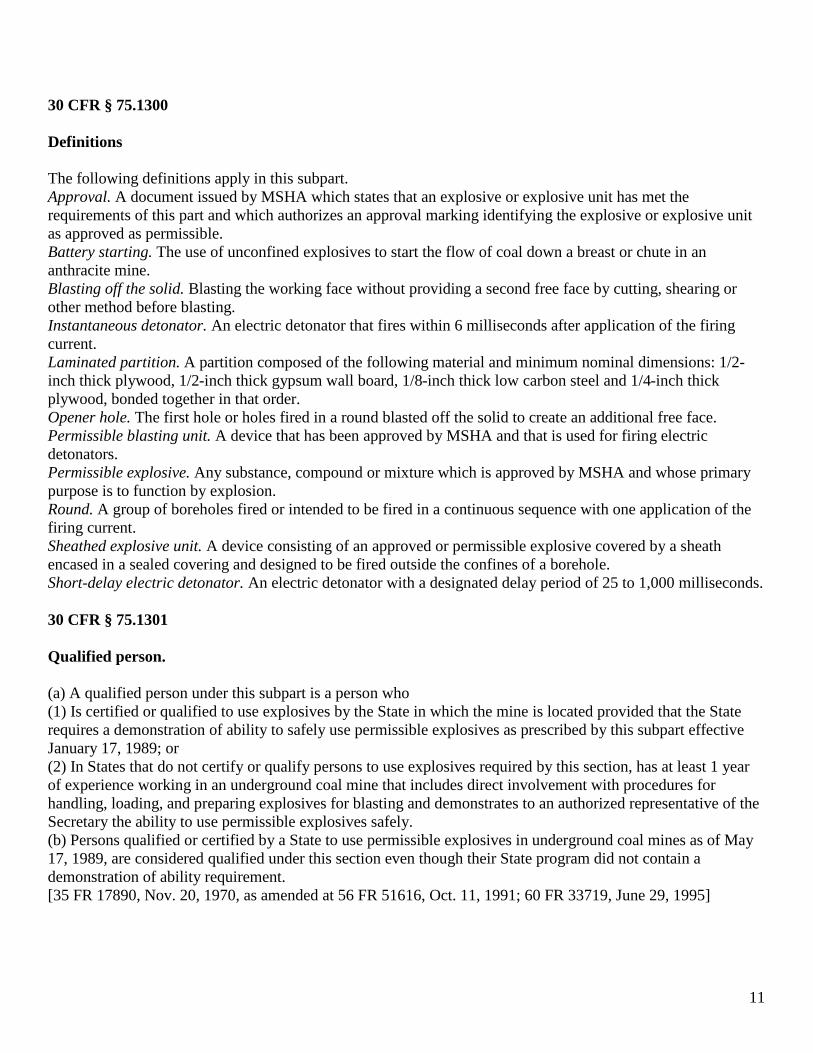
30 CFR § 75.1300 Definitions The following definitions apply in this subpart. Approval. A document issued by MSHA which states that an explosive or explosive unit has met the requirements of this part and which authorizes an approval marking identifying the explosive or explosive unit as approved as permissible. Battery starting. The use of unconfined explosives to start the flow of coal down a breast or chute in an anthracite mine. Blasting off the solid. Blasting the working face without providing a second free face by cutting, shearing or other method before blasting. Instantaneous detonator. An electric detonator that fires within 6 milliseconds after application of the firing current. Laminated partition. A partition composed of the following material and minimum nominal dimensions: 1/2-inch thick plywood, 1/2-inch thick gypsum wall board, 1/8-inch thick low carbon steel and 1/4-inch thick plywood, bonded together in that order. Opener hole. The first hole or holes fired in a round blasted off the solid to create an additional free face. Permissible blasting unit. A device that has been approved by MSHA and that is used for firing electric detonators. Permissible explosive. Any substance, compound or mixture which is approved by MSHA and whose primary purpose is to function by explosion. Round. A group of boreholes fired or intended to be fired in a continuous sequence with one application of the firing current. Sheathed explosive unit. A device consisting of an approved or permissible explosive covered by a sheath encased in a sealed covering and designed to be fired outside the confines of a borehole. Short-delay electric detonator. An electric detonator with a designated delay period of 25 to 1,000 milliseconds. 30 CFR § 75.1301 Qualified person. (a) A qualified person under this subpart is a person who (1) Is certified or qualified to use explosives by the State in which the mine is located provided that the State requires a demonstration of ability to safely use permissible explosives as prescribed by this subpart effective January 17, 1989; or (2) In States that do not certify or qualify persons to use explosives required by this section, has at least 1 year of experience working in an underground coal mine that includes direct involvement with procedures for handling, loading, and preparing explosives for blasting and demonstrates to an authorized representative of the Secretary the ability to use permissible explosives safely. (b) Persons qualified or certified by a State to use permissible explosives in underground coal mines as of May 17, 1989, are considered qualified under this section even though their State program did not contain a demonstration of ability requirement. [35 FR 17890, Nov. 20, 1970, as amended at 56 FR 51616, Oct. 11, 1991; 60 FR 33719, June 29, 1995]

12
30 CFR § 75.1310 Explosives and blasting equipment. (a) Only permissible explosives, approved sheathed explosive units, and permissible blasting units shall be taken or used underground. (b) Black blasting powder, aluminum-cased detonators, aluminum-alloy-cased detonators, detonators with aluminum leg wires, and safety fuses shall not be taken or used underground. (c) Explosives shall be fired only with a permissible blasting unit used in a manner consistent with its approval. Blasting units approved by MSHA that have approval labels specifying use with short-delay detonators with delay periods between 25-500 milliseconds are accepted to fire short-delay detonators up to 1,000 milliseconds, instantaneous detonators and long period delay detonators for anthracite mines. (d) Permissible explosives and sheathed explosive units shall not be used underground when they are below the minimum product firing temperature specified by the approval. Explosives previously approved which do not specify a minimum firing temperature are permissible for use so long as the present approval is maintained. (e) Electric detonators shall be compatible with the blasting unit and have sufficient strength to initiate the explosives being used. 30 CFR § 75.1311 Transporting explosives and detonators. (a) When explosives and detonators are to be transported underground-- (1) They shall be enclosed in separate, substantially constructed containers made of nonconductive material, with no metal or other conductive materials exposed inside, except as specified in paragraph (d) of this section; and (2) Each container of explosives and of detonators shall be indelibly marked with a readily visible warning identifying the contents. (b) When explosives and detonators are transported by any cars or vehicles-- (1) The cars or vehicles shall be marked with warnings to identify the contents as explosive. The warnings shall be readily visible to miners approaching from any direction and in indelible letters; (2) Explosives and detonators shall be transported either in separate cars or vehicles, or if in the same cars or vehicles as follows: (b)(2)(i) Class A and Class C detonators in quantities greater than 1,000 shall be kept in the original containers as shipped from the manufacturer and separated from explosives by a hardwood partition at least 4 inches thick, a laminated partition or equivalent; and (b)(2)(ii) Class A and Class C detonators in quantities of no more than 1,000 shall be separated from explosives by a hardwood partition at least 4 inches thick, a laminated partition or equivalent. (3) No persons, other than those necessary to operate the equipment or to accompany the explosives and detonators, shall be transported with explosives and detonators, and (4) When explosives and detonators are transported using trolley locomotives-- (b)(4)(i) Trips carrying explosives and detonators shall be separated from all other mantrips by at least a 5-minute interval; and (b)(4)(ii) Cars containing explosives or detonators shall be separated from the locomotives by at least one car that is empty or that contains noncombustible materials. (c) When explosives and detonators are transported on conveyor belts-- (1) Containers of explosives shall be separated from containers of detonators by at least 50 feet;
13
(2) At least 6 inches of clearance shall be maintained between the top of any container of explosives or container of detonators and the mine roof or other obstruction; (3) Except when persons are riding the belt to accompany explosives or detonators, a person shall be at each transfer point between belts and at the unloading location; and (4) Conveyor belts shall be stopped before explosives or detonators are loaded or unloaded. (d) When explosives and detonators are transported by hand they shall be carried in separate, nonconductive, closed containers. 30 CFR § 75.1312 Explosives and detonators in underground magazines. (a) The quantity of explosives kept underground shall not be more than is needed for 48 hours of use. (b) Except as provided in §75.1313, explosives and detonators taken underground shall be kept in-- (1) Separate, closed magazines at least 5 feet apart; or (2) The same closed magazine when-- (b)(2)(i) Separated by a hardwood partition at least 4 inches thick; or (b)(2)(ii) Separated by a laminated partition; or (b)(2)(iii) Separated by a device that is equivalent. (c) Only explosives and detonators shall be kept in underground magazines. (d) Magazines shall be substantially constructed and all interior surfaces shall be made of nonconductive material, with no metal or other conductive material exposed inside. (e) All magazines shall be-- (1) Located at least 25 feet from roadways and any source of electric current; (2) Located out of the direct line of the forces from blasting; and (3) Kept as dry as practicable. (f) Magazine locations shall be posted with indelibly marked and readily visible warnings indicating the presence of explosives. (g) Only materials and equipment to be used in blasting shall be stored at magazine locations. 30 CFR § 75.1313 Explosives and detonators outside of magazines. (a) The quantity of explosives outside a magazine for use in a working section or other area where blasting is to be performed shall-- (1) Not exceed 100 pounds; or (2) Not exceed the amount necessary to blast one round when more than 100 pounds of explosives is required. (b) Explosives and detonators outside a magazine that are not being transported or prepared for loading boreholes shall be kept in closed separate containers made of nonconductive material with no metal or other conductive material exposed inside and the containers shall be-- (1) At least 15 feet from any source of electric current; (2) Out of the direct line of the forces from blasting; (3) In a location to prevent damage by mobile equipment; and (4) Kept as dry as practicable. (c) Explosives and detonators not used during the shift shall be returned to a magazine by the end of the shift.
14
30 CFR § 75.1314 Sheathed explosive units. (a) A separate instantaneous detonator shall be used to fire each sheathed explosive unit. (b) Sheathed explosive units shall be primed and placed in position for firing only by a qualified person or a person working in the presence of and under the direction of a qualified person. To prime a sheathed explosive unit, the entire detonator shall be inserted into the detonator well of the unit and be held securely in place. (c) Sheathed explosive units shall not be primed until immediately before the units are placed where they are to be fired. A sheathed explosive unit shall not be primed if it is damaged or deteriorated. (d) Except in anthracite mines, rock dust shall be applied to the roof, ribs and floor within a 40-foot radius of the location where the sheathed explosive units are to be fired. (e) No more than three sheathed explosive units shall be fired at one time. (f) No sheathed explosive unit shall be fired in contact with another sheathed explosive unit. 30 CFR § 75.1315 Boreholes for explosives. (a) All explosives fired underground shall be confined in boreholes except (1) Sheathed explosives units and other explosive units approved by MSHA for firing outside the confines of a borehole; and (2) Shots fired in anthracite mines for battery starting or for blasting coal overhangs. No person shall go inside a battery to start the flow of material. (b) Each borehole in coal for explosives shall be at least 24 inches from any other borehole and from any free face, unless prohibited by the thickness of the coal seam. (c) Each borehole in rock for explosives shall be at least 18 inches from any other borehole in rock, at least 24 inches from any other borehole in coal, and at least 18 inches from any free face. (d) No borehole that has contained explosives shall be used for starting any other hole. (e) When blasting slab rounds off the solid, opener holes shall not be drilled beyond the rib line. (f) When coal is cut for blasting, the coal shall be supported if necessary to maintain the stability of the column of explosives in each borehole. 30 CFR § 75.1316 Preparation before blasting. (a)(1) All nonbattery-powered electric equipment, including cables, located within 50 feet from boreholes to be loaded with explosives or the sites where sheathed explosive units are to be placed and fired shall be deenergized or removed to at least 50 feet from these locations before priming of explosives. Battery-powered equipment shall be removed to at least 50 feet from these locations before priming of explosives. (2) As an alternative to paragraph (a)(1) of this section, electric equipment, including cables, need not be deenergized or removed if located at least 25 feet from these locations provided stray current tests conducted prior to priming the explosives detect stray currents of 0.05 ampere or less through a 1-ohm resistor. (a)(2)(i) Tests shall be made at floor locations on the perimeter, on energized equipment frames and on repaired areas of energized cables within the area between 25 to 50 feet from the locations where the explosives are to be primed.

15
(a)(2)(ii) Tests shall be conducted using a blasting multimeter or other instrument specifically designed for such use. (3) The blasting cable or detonator circuitry shall not come in contact with energized electric equipment, including cables. (b) Before loading boreholes with explosives, each borehole shall be cleared and its depth and direction determined. (c) No borehole drilled beyond the depth of cut coal shall be loaded with explosives unless that portion of the borehole deeper than the cut is tamped with noncombustible material. (d) When two working faces are approaching each other, cutting, drilling and blasting shall be done at only one working face at a time if the two faces are within 25 feet of each other. [35 FR 17890, Nov. 20, 1970, as amended at 56 FR 51616, Oct. 11, 1991] 30 CFR § 75.1317 Primer cartridges. (a) Primer cartridges shall be primed and loaded only by a qualified person or a person working in the presence of and under the direction of a qualified person. (b) Primer cartridges shall not be primed until immediately before loading boreholes. (c) Only a nonsparking punch shall be used when priming explosive cartridges. (d) Detonators shall be completely within and parallel to the length of the cartridge and shall be secured by half-hitching the leg wires around the cartridge or secured by an equally effective method. 30 CFR § 75.1318 Loading boreholes. (a) Explosives shall be loaded by a qualified person or a person working in the presence of and under the direction of a qualified person. (b) When boreholes are being loaded, no other work except that necessary to protect persons shall be done in the working place or other area where blasting is to be performed. (c) When loading boreholes drilled at an angle of 45 degrees or greater from the horizontal in solid rock or loading long holes drilled upward in anthracite mines-- (1) The first cartridge in each borehole shall be the primer cartridge with the end of the cartridge containing the detonator facing the back of the borehole; and (2) The explosive cartridges shall be loaded in a manner that provides contact between each cartridge in the borehole. (d) When loading other boreholes-- (1) The primer cartridge shall be the first cartridge loaded in the borehole; (2) The end of the cartridge in which the detonator is inserted shall face the back of the borehole; and (3) The primer cartridge and other explosives shall be pushed to the back of the borehole in a continuous column with no cartridge being deliberately crushed or deformed. (e) An explosive shall not be loaded into a borehole if it is damaged, deteriorated or if the cartridge is incompletely filled. (f) Explosives of different brands, types or cartridge diameters shall not be loaded in the same borehole. (g) Only nonconductive, nonsparking tamping poles shall be used for loading and tamping boreholes. The use of nonsparking connecting devices for extendable tamping poles is permitted. [53 FR 46786, Nov. 18, 1988; 54 FR 888, Jan. 10, 1989]

16
30 CFR § 75.1319 Weight of explosives permitted in boreholes in bituminous and lignite mines. (a) The total weight of explosives loaded in any borehole in bituminous and lignite mines shall not exceed 3 pounds except when blasting solid rock in its natural deposit. (b) The total weight of explosives loaded in a borehole less than 6 feet deep in bituminous and lignite mines shall be reduced by 1/2 pound for each foot of borehole less than 6 feet. 30 CFR § 75.1320 Multiple-shot blasting. (a) No more than 20 boreholes shall be fired in a round unless permitted in writing by the District Manager under §75.1321. (b) Instantaneous detonators shall not be used in the same circuit with delay detonators in any underground coal mine. (c) In bituminous and lignite mines, only detonators with delay periods of 1,000 milliseconds or less shall be used. (d) When blasting in anthracite mines, each borehole in a round shall be initiated in sequence from the opener hole or holes. (e) Arrangement of detonator delay periods for bituminous and lignite mines shall be as follows: (1) When blasting cut coal-- (e)(1)(i) The first shot or shots fired in a round shall be initiated in the row nearest the kerf or the row or rows nearest the shear; and (e)(1)(ii) After the first shot or shots, the interval between the designated delay periods of successive shots shall be at least 50 milliseconds but not more than 100 milliseconds. (2) When blasting coal off the solid-- (e)(2)(i) Each shot in the round shall be initiated in sequence from the opener hole or holes; and (e)(2)(ii) After the first shot or shots, the interval between the designated delay periods of successive shots shall be at least 50 milliseconds but not more than 100 milliseconds.
17
Alcohol, Tobacco, Firearms and Explosives Permit
In addition to Virginia and MSHA regulations, a mine operator must have a user permit from the
Department of Alcohol, Tobacco, Firearms, and Explosives. ATF publication 5400 states, “Attorney General shall by regulation prescribe, including the names of and appropriate identifying information regarding all employees who will be authorized by the applicant to possess explosive materials, as well as fingerprints and a photograph of each responsible person. “

18
EXPLOSIVES
EXPLOSIVES PROPERTIES: An explosive is a chemical compound that is ignited by heat, shock, impact, friction or a combination of these conditions. The chemical compound decomposes very rapidly resulting in detonation. An explosive detonation results in a rapid release of heat and large quantities of high pressure gases. These gases expand rapidly with great force and that produces fragmentation of the confined material. The very hot gases produce extremely high pressures within a borehole and it is these pressures that create fragmentation. Coal mining is the nation’s largest user of explosives.
PERMISSIBLE EXPLOSIVES
PERMISSIBLE: Permissible means a device, process, equipment or method classified by the MSHA. This classification adopted by the Chief, Division of Mines and includes all requirements, restrictions, exceptions, limitations and conditions attached to this classification. Permissible explosives are those which have passed rigid tests set forth and conducted by the Mine Safety and Health Administration (MSHA). Permissible explosives are designed for underground use where the presence of explosive gases and coal dust present an abnormal blasting hazard. Nitroglycerin-based and water-gel explosives are the most common permissible types used underground. Permissible explosives must pass non-ignition tests when fired unstemmed into a mixture of natural gas, air and bituminous coal dust. Permissible explosives must be used in a permissible manner. MSHA must approve all explosives used underground as being permissible. A “permissible certificate of approval” is a formal document issued by MSHA stating that an explosive has met the specifications and requirements of permissibility. This certificate authorizes the use of markings signifying a “permissible explosive”. CATEGORIES OF PERMISSIBLE EXPLOSIVES: Permissible explosives are categorized as granular or gelatinous dynamite and water-gel types.

19
The principal shortcoming of dynamite is its nitroglycerin content which makes it very hazardous to manufacture, transport, store and use. For these reasons, most of the major explosive companies are phasing dynamite out of production and this subject does not warrant further discussion. Water-gel explosives are safer to manufacture, transport, store and use because efforts are aimed at elimination nitroglycerin as a base ingredient. Water-gel explosives consist of oxidizing salts, fuels and sensitizers dissolved and thickened to aid in producing a water resistant compound. Water-gel explosives produce excellent fragmentation, reduce smoke, reduce toxic fumes and eliminate nitroglycerin headaches. The energy, density and velocity of water-gel explosives have high manufacturer standards. Blasting efficiency and safety are dependent upon primary confinement and proper use. Water-gel explosives are reliably sensitive to priming but more resistant than dynamite to accidental initiation from abusive impact, shock or fire. These characteristics provide a great safety factor. CHARACTERISTICS OF EXPLOSIVES: All explosives produce a flame which varies in volume, duration and temperature. Permissible explosives are designed to produce a flame of small volume, short duration and low temperature. Gas and dust ignitions are reduced by using permissible explosives. The probability of a gas or dust ignition is significantly reduced when permissible explosives are used in a permissible manner. MIXING BRANDS OF EXPLOSIVES: Different brands or types of explosives shall never be mixed in any shot or borehole. RENDERING PERMISSIBLE EXPLOSIVES NONPERMISSIBLE:
Three common problems which cause permissible explosives to become nonpermissible: Moisture – causes explosives to leak. Age – causes instability of explosives. Improper storage – cause damage to the design characteristics of explosives.
20
PERMISSIBLE EXPLOSIVES REQUIRED: Safety is the main reason permissible explosives are required to be used underground. The use of permissible explosives has increased while the explosives accident rate has decreased. The most frequent cause of blasting accidents is improper guarding and failure to account for all mining personnel around the blast area. Precautions must be taken to ensure that all personnel are in a safe location prior to the firing of a shot. No one should ever return to a shot area until the smoke has cleared and the visibility allows close inspection of the roof and ribs.
21
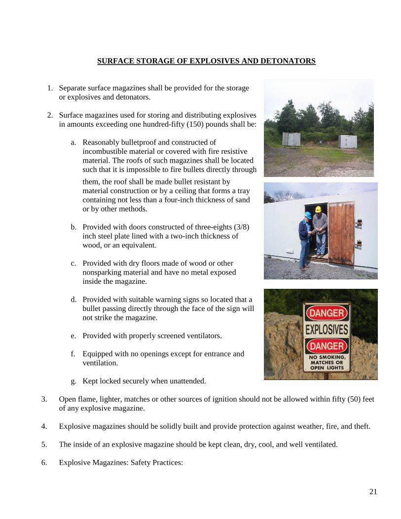
SURFACE STORAGE OF EXPLOSIVES AND DETONATORS
1. Separate surface magazines shall be provided for the storage or explosives and detonators.
2. Surface magazines used for storing and distributing explosives
in amounts exceeding one hundred-fifty (150) pounds shall be:
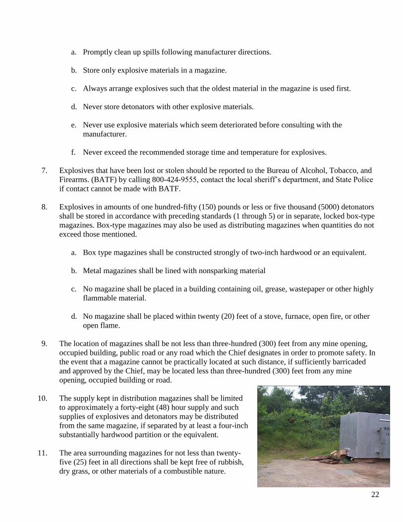
a. Reasonably bulletproof and constructed of incombustible material or covered with fire resistive material. The roofs of such magazines shall be located such that it is impossible to fire bullets directly through them, the roof shall be made bullet resistant by material construction or by a ceiling that forms a tray containing not less than a four-inch thickness of sand or by other methods.
b. Provided with doors constructed of three-eights (3/8)
inch steel plate lined with a two-inch thickness of wood, or an equivalent.
c. Provided with dry floors made of wood or other
nonsparking material and have no metal exposed inside the magazine.
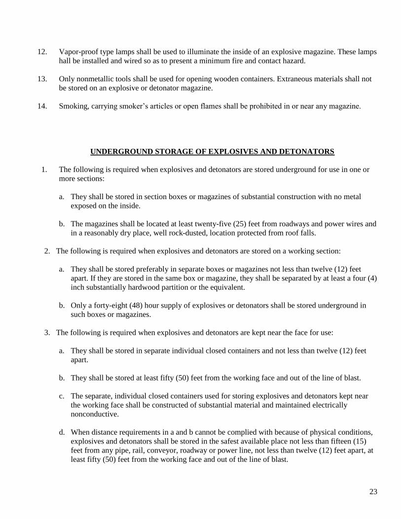
d. Provided with suitable warning signs so located that a
bullet passing directly through the face of the sign will not strike the magazine.
e. Provided with properly screened ventilators.
f. Equipped with no openings except for entrance and
ventilation.
g. Kept locked securely when unattended.
3. Open flame, lighter, matches or other sources of ignition should not be allowed within fifty (50) feet of any explosive magazine.
4. Explosive magazines should be solidly built and provide protection against weather, fire, and theft.
5. The inside of an explosive magazine should be kept clean, dry, cool, and well ventilated.
6. Explosive Magazines: Safety Practices:
22
a. Promptly clean up spills following manufacturer directions.
b. Store only explosive materials in a magazine.
c. Always arrange explosives such that the oldest material in the magazine is used first.
d. Never store detonators with other explosive materials.
e. Never use explosive materials which seem deteriorated before consulting with the manufacturer.
f. Never exceed the recommended storage time and temperature for explosives.
7. Explosives that have been lost or stolen should be reported to the Bureau of Alcohol, Tobacco, and
Firearms. (BATF) by calling 800-424-9555, contact the local sheriff’s department, and State Police if contact cannot be made with BATF.
8. Explosives in amounts of one hundred-fifty (150) pounds or less or five thousand (5000) detonators
shall be stored in accordance with preceding standards (1 through 5) or in separate, locked box-type magazines. Box-type magazines may also be used as distributing magazines when quantities do not exceed those mentioned.
a. Box type magazines shall be constructed strongly of two-inch hardwood or an equivalent.
b. Metal magazines shall be lined with nonsparking material
c. No magazine shall be placed in a building containing oil, grease, wastepaper or other highly
flammable material.
d. No magazine shall be placed within twenty (20) feet of a stove, furnace, open fire, or other open flame.
9. The location of magazines shall be not less than three-hundred (300) feet from any mine opening,
occupied building, public road or any road which the Chief designates in order to promote safety. In the event that a magazine cannot be practically located at such distance, if sufficiently barricaded and approved by the Chief, may be located less than three-hundred (300) feet from any mine opening, occupied building or road.
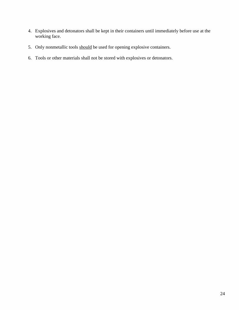
10. The supply kept in distribution magazines shall be limited
to approximately a forty-eight (48) hour supply and such supplies of explosives and detonators may be distributed from the same magazine, if separated by at least a four-inch substantially hardwood partition or the equivalent.
11. The area surrounding magazines for not less than twenty-
five (25) feet in all directions shall be kept free of rubbish, dry grass, or other materials of a combustible nature.
23
12. Vapor-proof type lamps shall be used to illuminate the inside of an explosive magazine. These lamps hall be installed and wired so as to present a minimum fire and contact hazard.
13. Only nonmetallic tools shall be used for opening wooden containers. Extraneous materials shall not
be stored on an explosive or detonator magazine.
14. Smoking, carrying smoker’s articles or open flames shall be prohibited in or near any magazine.
UNDERGROUND STORAGE OF EXPLOSIVES AND DETONATORS
1. The following is required when explosives and detonators are stored underground for use in one or more sections:
a. They shall be stored in section boxes or magazines of substantial construction with no metal
exposed on the inside.
b. The magazines shall be located at least twenty-five (25) feet from roadways and power wires and in a reasonably dry place, well rock-dusted, location protected from roof falls.
2. The following is required when explosives and detonators are stored on a working section:
a. They shall be stored preferably in separate boxes or magazines not less than twelve (12) feet
apart. If they are stored in the same box or magazine, they shall be separated by at least a four (4) inch substantially hardwood partition or the equivalent.
b. Only a forty-eight (48) hour supply of explosives or detonators shall be stored underground in
such boxes or magazines.
3. The following is required when explosives and detonators are kept near the face for use:
a. They shall be stored in separate individual closed containers and not less than twelve (12) feet apart.
b. They shall be stored at least fifty (50) feet from the working face and out of the line of blast.
c. The separate, individual closed containers used for storing explosives and detonators kept near
the working face shall be constructed of substantial material and maintained electrically nonconductive.
d. When distance requirements in a and b cannot be complied with because of physical conditions,
explosives and detonators shall be stored in the safest available place not less than fifteen (15) feet from any pipe, rail, conveyor, roadway or power line, not less than twelve (12) feet apart, at least fifty (50) feet from the working face and out of the line of blast.
24
4. Explosives and detonators shall be kept in their containers until immediately before use at the working face.
5. Only nonmetallic tools should be used for opening explosive containers.
6. Tools or other materials shall not be stored with explosives or detonators.
25
UNDERGROUND TRANSPORTATION OF EXPLOSIVES AND DETONATORS
1. The following is required when explosives or detonators are transported underground:
a. They shall be transported in individual, closed containers that shall be made of substantial,
nonconductive material maintained in good condition.
b. They shall be transported in substantially covered cars or in special, substantially, covered containers used specifically for transporting explosives or detonators when they are transported in cars, shuttle cars or other mobile equipment.
c. The bodies and covers of such cars and containers shall be constructed or lined with
nonconductive material.
d. Explosives and detonators hauled in the same explosive car or in the same special container shall be separated by at least a four (4) inch substantially fastened hardwood partition or the equivalent.
e. Explosives or detonators shall not be transported on the same trip with mining personnel.
f. Explosives or detonators that are transported in special cars or containers in cars shall be hauled in
special trips not connected to any other trip. This shall not prohibit the use of such additional cars as needed to lower a trip or to haul supplies including timbers. Such materials transported on the same trip as explosives shall not project above the top of the car.
g. Flammable materials such as oil, grease, hydraulic fluid or diesel fuel, shall not be transported on
the same trip with explosives.
h. Explosives or detonators shall not be hauled into or out of the mine within five (5) minutes preceding or following a man-trip or any other trip. If traveling against the air current, the man-trip shall precede the explosives trip. If traveling with the air current, the man-trip shall follow the explosives trip.
i. Explosives may be transported in the original and unopened case or in suitable individual
containers to an underground distribution magazine when it is impractical to comply with b and c such as in low coal seams
j. Explosives and detonators shall be transported underground by belt only under the following
conditions:
1. In the original and unopened case, in special closed cases constructed of nonconductive material, or in suitable individual containers.
2. Clearance requirements shall be the same as those for transporting mining personnel on belts.
3. Suitable loading and unloading stations shall be provided.
26
4. Stop controls shall be provided at loading and unloading points and an attendant shall supervise the loading and unloading of explosives and detonators.
k. Explosives and detonators shall not be transported on flight or shaking conveyors, scrapers,
mechanical loading machines, locomotives, cutting machines, drill tracks, or any self-propelled mobile equipment. This shall not prohibit the transportation of explosives or detonators in special closed containers in shuttle cars or in equipment designed especially to transport such explosives or detonators.
l. Always load and unload explosives and detonators very carefully.
27
COAL DUST
COAL DUST CONTROL: Coal dust is the general name for coal particles of small size. Coal dust in mines present a major explosion hazard whether located in the vicinity of a blasting operation or distributed throughout the mine. All mining processes produce coal dust. Most coal dust is produced when coal is being blasted, cut, and loaded at the working face. As coal is cut and loaded, dust is produced, rises into the air, travels with the ventilating current and settles throughout the mine. ROCK DUSTING: Rock dusting is a control measure used to combat explosive dusts in coal mines. The dusting of all underground areas with powdered limestone (rock dust) dilutes the coal dust in the mine atmosphere therefore reducing an explosion hazard. All underground areas of a coal mine shall be rock dusted within forty (40) feet from a working face. All crosscuts that are less than forty (40) feet from a working face shall also be rock dusted. Closer than forty (40) feet, water and ventilation are the most effective dust control measures. A shot firer must coordinate this requirement with the mine foreman, section foreman, to ensure adequate rock dust has been applied before firing any shot or group of shots.
28
SHOOTING CUT COAL
CUTTING COAL: There are various methods for the cutting of coal in underground coal mines. The cutting of coal gives additional space for the expansion of coal when blasted, since 1 cubic foot of solid coal becomes 1.6 feet of loose coal after it has been blasted. The proper location for the cut is normally determined by the physical characteristics of the coal seam, the stability of the roof and the firmness of the bottom. It is extremely important to cut each rib on a straight line parallel to the center of the entry to prevent “gripping the ribs”. Gripping the ribs results in the back of the cut being wider than the open face to give a funnel effect. Various methods of cutting coal are: bottom cut, top cut, rib shear cut, center cut, or a combination of these different types of cutting. Bottom cutting is the most common type of cut used in underground mining and is used in areas of soft bottom. Unlike to cutting, the cutting dust or “bug dust” is dragged back under and packed into the cut area or “kerf” when bottom cutting is utilized. It is most important that the machinery be kept in good repair to ensure a clean kerf. If the undercut is not clean, there will not be room for normal expansion of the broken coal. A water-filled kerf will result in the same effect. If the water cannot be removed, additional drill holes may be necessary. Top cutting has become more popular and more efficient with the use of delay blasting techniques. Top cutting has the advantage of establishing a smooth plane of relief between the mine roof and the coal seam. This advantage minimizes the blasting effect and leaves the mine roof undisturbed to the extent practical. The “bug dust” cannot be dragged under the cut and therefore eliminates kerf cleaning. Top cutting ensures a clean kerf, allowing maximum expansion space for the broken coal. Provided the explosives are well confined, the maximum blasting efficiency is obtained from the detonation explosive energy. The entire cut is fired in one operation with each hole firing on an individual time period. The Top cut offers maximum confinement for all the explosives charges and helps reduce kerf obstruction that occurs with bottom cutting. Rib shear and center cutting are usually used in combination with the other types of cutting. A center cut is frequently used where heavy horizontal rock layers are presented in the coal seam. This cut is usually located directly under the rock layer allowing the rock to be more easily broken from boreholes located over the rock layer. Center, off-center or rib shears are used to provide additional relief in seams that are difficult to blast. Two or more drill holes can usually be eliminated by using a rib shear. The rib shear is sometimes used to establish a solid, smooth rib and helps to eliminate coal-rock brows. All types of brows present a special hazard to all equipment operators as well as fall hazard to all miners.
29
SHOOTING OFF THE SOLID
“Shooting off the solid” is another method used in the shooting of coal, but there are not cuts made. A written permit to “shoot off the solid” must be granted by the Chief, Division of Mines. The Chief shall prescribe the conditions under which solid shooting shall be done. Two methods are used to “shoot off the solid”. These methods are the “V cut” and “slabbing”. The method used depends on the mining conditions. The number of holes required will depend on the height of the seam and the characteristics of the seam. The “V cut” will reduce the number of delay periods needed and will usually result in firmer ribs on both sides of the entry. A short hole approximately six feet deep is drilled in a V or wedge configuration with the back of the holes as close in line as possible. The holes across the face are drilled to the full depth of the proposed round in a fan pattern out to the ribs. By delaying to the ribs, the broken coal will be piled toward the middle of the entry that facilitates easier loading of the coal. The other method used for “shooting off the solid” is the slabbing method. With this pattern the breaker hole is drilled approximately six feet deep and is drilled close to the rib line. Every effort should be made to never exceed three feet of burden with this first hole. These commonly called “breaker holes” are usually alternated from side to side to assist in maintaining as straight a rib line as possible. The remaining holes are drilled in a fan pattern until the rib hole, opposite side as the breaker hole, is parallel to the entry. It is essential to delay the holes in sequence away from the breaker hole side to create relief for each row of holes. When “shooting off the solid” the explosives ratio will normally be higher than blasting cut coal. The ratio will vary from three-quarters pound per ton to one and one fourth pound per ton depending on the physical characteristics of the coal seam. A given quantity volume of solid coal will expand approximately 30 percent when broken. To achieve the displacement and fragmentation necessary for high production mining, all phases of face preparation, cutting, drilling and blasting must be considered as an intrinsic unit completely dependent on the other for successful mechanical loading of coal. Abode (mud cap) or other open, unconfined shots shall not be fired in any mine.
30
DRILLING
Proper drilling with accurate alignment of the holes is fundamental to good blasting. When holes are properly located, alignment and depth are accurately controlled, fewer holes and less explosives will be required to adequately fragment and displace the coal for maximum loadability. Before drilling, the depth and limits of the cut should be determined by running the tamping stick under the cut when a face has been cut. The holes should be drilled parallel to the center line of the entry. The boreholes shall never be drilled beyond the limits of the cut, nor into the roof, rib or mine floor. This would cause the explosive charge to fire in the solid when boreholes are drilled beyond the limits of the cut, into the roof, rib or mine floor. The common practice is to drill approximately 6 inches less than the length of the cut. The shot firer must measure the length of the cut. The placement of the holes will vary with the individual coal seam. In general, the holes should be drilled as level as possible and parallel to the roof. Each hole must have a minimum burden of 18 inches in all directions if the height of the coal permits. In most coal seams the holes can be located with 3 to 4 feet of burden. The holes should be spaced to ensure that one hole will not rob any other hole and that each hole will have adequate confinement to achieve maximum efficiency and safety. Each drill hole should be cleaned using a bar with a spoon on the end of it. This helps prevent any air gaps that might cause a misfire or blowout. STRAY CURRENT One of the first precautions taken before charging any boreholes is to make a stray current check of the shot area using a blasters’ multimeter. Electric current flowing through power lines to electrical equipment from a battery, a generator, or a transformer will always return to that source by all available paths. These paths include: (1) additional conductors insulated form ground, such as electric cables: (2) conductors not insulated from ground for electric haulage, such as rails, and (3) the earth itself. If the return conductor between the load and the source is interrupted, the current will find another path and dangerously high ground currents may result. This hazard can be minimized if continuous metal objects are kept away from the immediate vicinity of electric blasting circuits. In addition, measurements for stray ground currents should be conducted before electric blasting caps are introduced into a particular location. Generally, in homogeneous ground AC or DC currents sufficient to detonate electric blasting caps rarely are found. That is because the resistance of the earth is usually high and the potential between two points close together is usually low. However, dangerous currents can be found when electric blasting cap leg wires contact separate conductive strata. Hazardous currents, greater than 50 milliamperes, can also reach electric blasting caps if the leg wires contact rails, pipelines, or ventilating ducts. The earth offers such a huge cross-section to vagabond extraneous current that even high resistance earth draws currents out of rails or ground conductors.
31
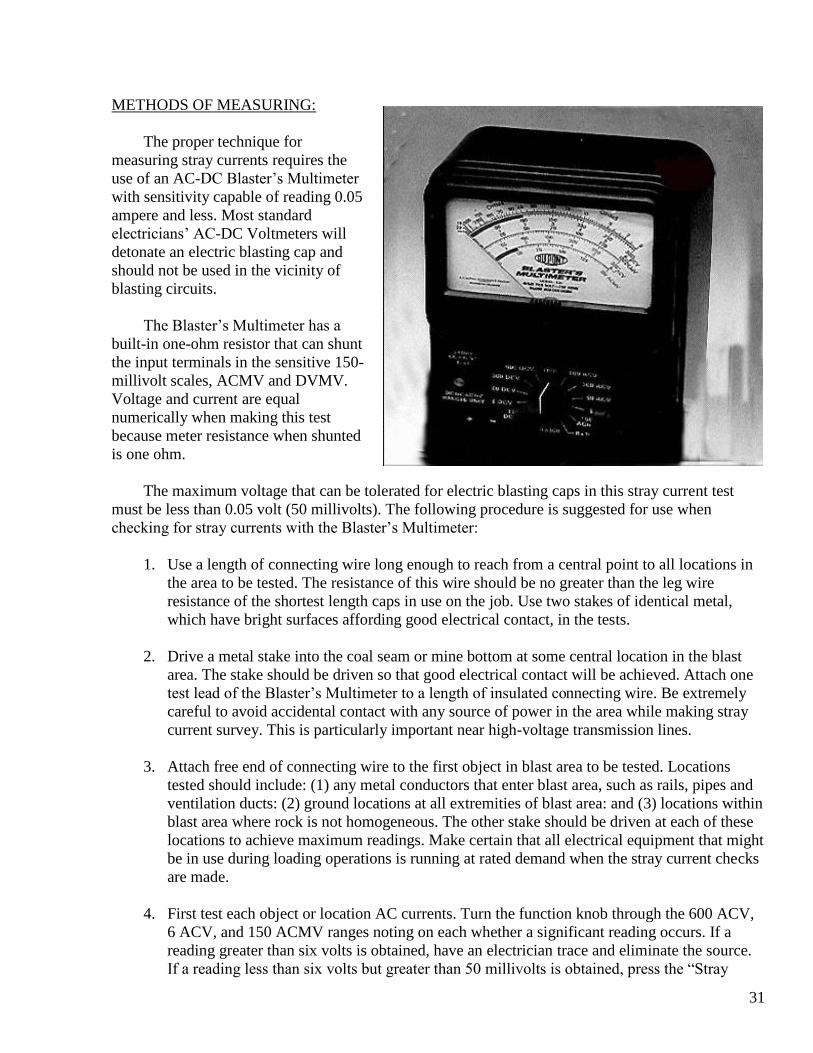
METHODS OF MEASURING: The proper technique for measuring stray currents requires the use of an AC-DC Blaster’s Multimeter with sensitivity capable of reading 0.05 ampere and less. Most standard electricians’ AC-DC Voltmeters will detonate an electric blasting cap and should not be used in the vicinity of blasting circuits. The Blaster’s Multimeter has a built-in one-ohm resistor that can shunt the input terminals in the sensitive 150-millivolt scales, ACMV and DVMV. Voltage and current are equal numerically when making this test because meter resistance when shunted is one ohm. The maximum voltage that can be tolerated for electric blasting caps in this stray current test must be less than 0.05 volt (50 millivolts). The following procedure is suggested for use when checking for stray currents with the Blaster’s Multimeter:
1. Use a length of connecting wire long enough to reach from a central point to all locations in
the area to be tested. The resistance of this wire should be no greater than the leg wire resistance of the shortest length caps in use on the job. Use two stakes of identical metal, which have bright surfaces affording good electrical contact, in the tests.
2. Drive a metal stake into the coal seam or mine bottom at some central location in the blast
area. The stake should be driven so that good electrical contact will be achieved. Attach one test lead of the Blaster’s Multimeter to a length of insulated connecting wire. Be extremely careful to avoid accidental contact with any source of power in the area while making stray current survey. This is particularly important near high-voltage transmission lines.
3. Attach free end of connecting wire to the first object in blast area to be tested. Locations
tested should include: (1) any metal conductors that enter blast area, such as rails, pipes and ventilation ducts: (2) ground locations at all extremities of blast area: and (3) locations within blast area where rock is not homogeneous. The other stake should be driven at each of these locations to achieve maximum readings. Make certain that all electrical equipment that might be in use during loading operations is running at rated demand when the stray current checks are made.
4. First test each object or location AC currents. Turn the function knob through the 600 ACV,
6 ACV, and 150 ACMV ranges noting on each whether a significant reading occurs. If a reading greater than six volts is obtained, have an electrician trace and eliminate the source. If a reading less than six volts but greater than 50 millivolts is obtained, press the “Stray

32
Current Test” button on 150 ACMV range to shunt the terminals with the one-ohm resistor. With the “Stray Current Test” button in use, a potential hazard is indicated if the reading is greater than 50 millivolts, or if the reading is less than 50 millivolts but fluctuates. The latter case indicates a situation where the stray current might increase to a hazardous level. In either case the source of stray current must be located and reduced to a safe level before using electric blasting caps. Shutting off electrical equipment, one unit at a time, while making measurements is often the best method of locating sources of stray AC currents. DC voltages do not contribute to the reading when on the 150 ACMV range. Therefore, this portion of the test shows AC sources only.
NOTE: The built in one-ohm resistor for the stray current test has a power rating of 10 watts. It can withstand continuous application of voltages up to three volts. Voltages up to six volts may be safely tested on the 150-millivolt range for short periods, five to ten seconds. Voltages exceeding six volts should be eliminated. Do not attempt to test them for current output capability.
5. Whether or not stray AC currents are detected, it is necessary to test for DC stray currents in a similar fashion. Turn the function knob successively through the 600 DCV, 300 DCV, 60 DCV, 6 DCV, and 150 DCMV ranges and note whether a significant reading occurs. Again, press the “Stray Current Test” button (in 150 DCMV range) if a reading less than 6 volts but more than 50 millivolts is obtained.
AC voltages do not contribute to the reading when on any DC range. Also, DC voltages do not contribute when on the 150 ACMV range. On the other AC ranges a DC source will read 1.11 times higher than its actual DC value. Therefore, if significant readings were obtained in both AC and DC millivolt stray current tests, the two must be added. A sum equal to or greater than 50 millivolts, equal to 50 milliamperes with the “Stray Current Test” switch depressed, indicates a potential hazard.
FREQUENCY OF TESTS: Stray current measurements should be made over a sufficient period of time to determine the fluctuations that are experienced when mining equipment is started or operated in the vicinity of the test. Electric blasting operations in highly conductive coal seams, in highly metallic rock formations, and in slightly acidic or alkaline wet area, as well as operations near electric distribution facilities, warrant frequent tests for the presence of hazardous ground current. CORRECTIVE STEPS: If AC and/or DC current readings exceed 0.05 amps (50 milliamperes), electrical blasting should be suspended until the hazard is reduced to a safe level. Subsequent electric blasting operations can be carried out safely by taking suitable precautions to keep stray currents below 50 milliamperes. The hazards that stray currents present to electric blasting caps can be greatly diminished by isolating all electric power lines near the blast area from ground and by providing a separate common bus wire bonded to the metal frames of all electrical equipment.
33
All rails, pipes, armored cables, ventilating ducts, and other conductors not designed to carry power should be electrically bonded together at frequent intervals and connected to single earth ground. This, in turn, should be isolated from power ground neutral bus. Power line insulation and insulators should be kept in good repair. Power and lighting circuits should be kept away from the blasting area during loading operations. Isolation of all loading wires and blasting circuits from ground and from possible current-carrying conductors are additional measures to reduce the stray current hazard. Lead lines should be checked for stray currents at periodic intervals. The insulated foil covers over the shunted leg wires of electric blasting caps provide the final defense against stray current hazards. These foil covers should not be removed until the loading operation is completed and caps are ready to be connected.
LOADING There is a tendency to use more explosives than necessary to properly fragment and displace coal for maximum loadability. This practice is not only an unnecessary expense, but can create several hazards. Overloading will result in:
1. More coal dust being thrown into suspension
2. Holes being robbed of their planned burdens
3. Reduction or elimination of confinement
4. Excessive smoke and fumes
5. Flying fragments of coal that can produce serious injuries
Normally loading one-third to one-half of the borehole depth will be sufficient to produce good
loadability. The maximum energy is required in the back of the hole to shear cut coal, when applicable, away from the solid coal. Additional explosives strung out to the front of the hole usually represent wasted energy.
Before loading any explosive, boreholes shall be cleaned, checked to see that they are properly
placed and drilled to the correct depth. The electric blasting cap should be imbedded in the first cartridge in the hole with the shell or
business end of the cap directed toward the collar of the hole and pointed toward to remainder of the explosives cartridge. The blasting cap should be secured with a half hitch around the primer cartridge. All the cartridges should be placed in the hole and the entire explosive column pushed to the back of the hole as a single unit. This will minimize column separation caused by coal dust between cartridges. Column separation can result in undetonated explosives in the broken coal.

34
BOREHOLE EXPLOSIVES: Without a permit, the amount of permissible explosives used shall not exceed one and one-half pounds per borehole if the borehole is 6 feet or less in depth. All explosives used underground shall be permissible Class A or Class B. The amount of permissible explosives used shall not exceed 3 pounds per borehole if the borehole is more than 6 feet in depth. The three pounds limit shall not apply to solid rock blasting. The explosive cartridges shall be charged in a continuous train and no cartridges shall be deliberately deformed or crushed. The cartridges should never be cut. The amount of explosives per foot or borehole is controlled by the diameter and density of the permissible explosive being used. NON-SPARKING PUNCH: A non-sparking punch is used to make a hole in the explosive cartridge for the detonator. Explosive cartridges should never be rolled between the hands to soften the stick for detonator insertion. This rolling effect creates friction and could change the density of explosives that may create a dangerous situation. DETONATOR PLACEMENT: The detonator shall be placed well into the first cartridge of explosives with the wires secured to the cartridge with a half-hitch tie. PRIMING: The primer is the cartridge of explosive containing the detonator. The primer cartridge should be placed in the back of the hole pointed toward the collar of the hole and toward the remaining cartridges in the borehole. All cartridges shall be in contact with each other, with the first cartridge touching the back of the borehole. Boreholes shall not be charged while any other work is performed in the shot area. The shot shall be fired before any other work is done in the zone of danger near the shot area except necessary action to safe guard all miners.
35
STEMMING
All stemming material used underground shall be non-combustible. The stemming shall consist of inert material such as clay, sand, or water. Clay is the most widely used stemming material. Water-stemming has also proven to be effective in providing confinement and reducing dust. Stemming with coal dust increases the probability of a gas or dust explosion as well as lowering the breakage efficiency of the explosives. Coal dust stemming should never be used. Adequate confinement (stemming) is one of the greatest factors that affect explosive efficiency. Boreholes that are more than 4 feet in depth shall have a minimum of 24 inches stemming. Boreholes that are less than 4 feet in depth shall have at least one half of the length of the borehole stemmed. Only non-metallic tamping bars shall be used in stemming boreholes.
36
WIRING
Three types of circuits are used in the wiring of explosives in underground mines. The three types of circuits are: series, series in parallel and parallel. SERIES CIRCUIT: The series circuit is the most common circuit pattern used when 40 or fewer boreholes are detonated. In a series circuit, all the electric detonators are connected in a line such that the current has only one path to follow with the same amount of current flowing through each detonator. When current leakage is a problem, the number of electric detonators should be reduced. A series circuit should be limited to 100 ohms or less total resistance. The minimum recommended firing current for a single series circuit is 1.5 amps DC or 2.0 amps AC. To determine the current which will flow in the series circuit, it is first necessary to determine the total resistance of that circuit. This is done by adding together the resistance of all elements within the series circuit. RT = RD + RC + RF Where RT = Total resistance (in ohms) RD = Detonators resistance (in ohms) RC = Connecting wire resistance (in ohms) RF = Firing line resistance (in ohms)
Applying the principles of ohm’s law is used to determine if the firing unit can supply sufficient voltage and current to overcome the complete circuit resistance while firing the shot. Keeping in mind that 1.5 amps DC or 2.0 amps AC is required to fire a single series, ohm’s laws is used to determine this factor. Ohm’s law I=V R Where I = current in amps V = voltage of firing unit or power source R = total resistance of circuit in ohms (RT) For example, find the current supplied to a series circuit which contains 12 detonators with 12 foot copper legwires, 100 feet of #20 AWG copper connecting wire and 200 feet of #14 AWG copper

37
firing line. Resistance of one detonator is 1.0 ohms, resistance of #20 connecting line is 10.15 ohms per 1000 feet, and resistance of #14 firing line is 2.53 ohms per 1000 feet.
1. Determine the total resistance of the detonators by multiplying the resistance of one
detonator by the number of detonators.
RD = 12 x 1.8 RD = 21.6 ohms
2. Determine the resistance of the connecting wire:
RC = 100 x 10.15 1000 RC = 1.01 ohms
3. Determine the resistance of the firing line: RF = 2 x 200 x 2.53 1000 RF = 1.01 ohms 2 is used in this formula because the firing line or shooting cable has 2 leads.
4. Determine the total resistance of the circuit by adding the detonator resistance, connecting wire resistance and firing line resistance. If connecting wire is not present in the circuit simply add the detonator resistance and the firing line resistance.
RT = RD + RC +RF RT = 21.6 + 1.01 +1.01 RT = 23.62
For a DC firing unit that can supply 50 volts, ohm’s law is used to determine if the unit will supply the recommended current of 1.5 amps to fire the shot.
I = V R I = 50 23.62 I = 2.11 amps
38
Since the calculated 2.11 amps exceed the minimum of 1.5 amps to fire a single series circuit, this is a satisfactory arrangement.
For a power line source such as 110 or 220 volts, use the source voltage 110, 220 etc. for V (voltage) in the ohm’s law formula. SPECIAL SAFETY PRECAUTION – “ARCING”: Where the magnitude and duration of the firing current is excessive, an arcing malfunction may occur. Electric detonators can be damaged if too much electrical energy is applied that may result in a misfired hole or a complete misfired shot. Too much firing current will generate excessive heat that cannot be dissipated and will result in an electrical arc. Under normal firing conditions, the amount of heat produced is dissipated. However, when excessive firing current is applied for too long a time duration such that the heat is not dissipated, arcing malfunctions will occur. Arcing damage can occur in delay electric blasting caps when current levels of 10 amps or more is delivered to an individual cap or an individual series when a series-parallel circuit has been used. Specific arcing limitations can be obtained by consultation with manufacturer of the explosives being used. The arcing malfunctions may create erratic timing (both fast and slow) of delay detonators that can result in less than satisfactory blasting results. The arcing malfunctions may also create detonator shell rupture, hole burned in shell, or ejection of the sealing plug that may produce a misfire and or hangfire. SERIES IN PARALLEL: In the series parallel circuit, the individual series are wired in parallel to complete the circuit. This type of circuit is commonly used when the total number of detonators in a blast exceed 50 or more. Each individual series should be limited to no more than 40 detonators and or a maximum resistance of 100 ohms. When current leakage is a problem, the number of electric detonators per series should be reduced. In the series parallel circuit, the total current flowing in the firing line (blasting cable) divides into each series. It is very important that the resistance of each series be the same or nearly the same as each of the other series. This is called series balancing and will ensure that the total current carried by the firing line is divided equally into each series. In addition, the use of the reverse hookup between the firing line and connecting line will also help to ensure equal current distribution to all the individual series. For any set of conditions there is an optimum number of series to obtain the maximum current through each of the series when using a series parallel circuit. If too few series are used, the current will be low because the resistance will be high. If too many series are used, the current per series will be low because the total current is split into too many series. In the series-parallel, each series contain the same number of detonators or the same resistance to ensure even current distribution. The leg wires of the detonators in each series are connected consecutively. A connection line is placed in a position such that each end of the individual series is

39
hooked to the connecting line. The connection line is usually about #14 gauge or a cable the same size of the blasting cable is used. To assure equal current distribution to each series one connecting line should be reversed. The heavy gauge (#14 or larger) connecting wire is used to reduce the total circuit resistance. The series-parallel circuit is most commonly used when a large number of detonators must be fired in the same shot area e.g. overcast shooting. At times, such a large number of detonators and a high total circuit resistance will exceed the output of a permissible firing unit. When necessary to use other than a permissible firing unit, a special permit shall be issued by MSHA describing the firing unit to be used, the condition, procedures and requirements that must be followed to fire this type of blast. It is unlawful and extremely dangerous to fire permissible explosives in a nonpermissible manner without permission to detonate any shot in such a manner. COMPUTING A SEREIS-PARALLEL CIRCUIT:
1. Add the detonator resistance in each series or row that should be the same or nearly the same.
2. Divide the resistance of one series or row by the total number of series or rows to get the total resistance of the detonators.
3. The connecting line resistance and firing line resistance is computed the same as in the series
circuit.
4. The total circuit resistance is computed by adding the detonator resistance, connecting wire resistance, and firing line resistance.
5. Ohm’s law is used to determine if the firing unit or power source can supply the required
current of 1.5 amps per series to fire the shot.
6. The current is computed by dividing the firing unit and power source voltage by the total circuit resistance; this represents the line current for the complete circuit.
NOTE: This current does not represent the current sub-divided to each series.
7. The series current is computed by dividing the line current for the whole circuit by the number of series or rows.
The recommended current for each series of a series parallel circuit should equal to or exceed 1.5 amps DC and 2.0 amps AC.

40
DELAY BLASTING CAPS (see diagram)
Figure 20. – Delay electric blasting cap.
Electric blasting cap consists of two (2) insulated legwires that pass through a waterproof seal and into a metal capsule containing a series of explosives powders. The leg wires pass through a rubber or plastic plug that is securely crimped in the end of the cap shell that forms a water resistant closure. Leg wires of various lengths are manufactured to accommodate different borehole depths. The ends of the leg wires are joined together inside the cap by a high resistant, filament wire called the “bridge wire”. Electrical energy flows from the power source, through the leg wires and through the “bridge wire”.
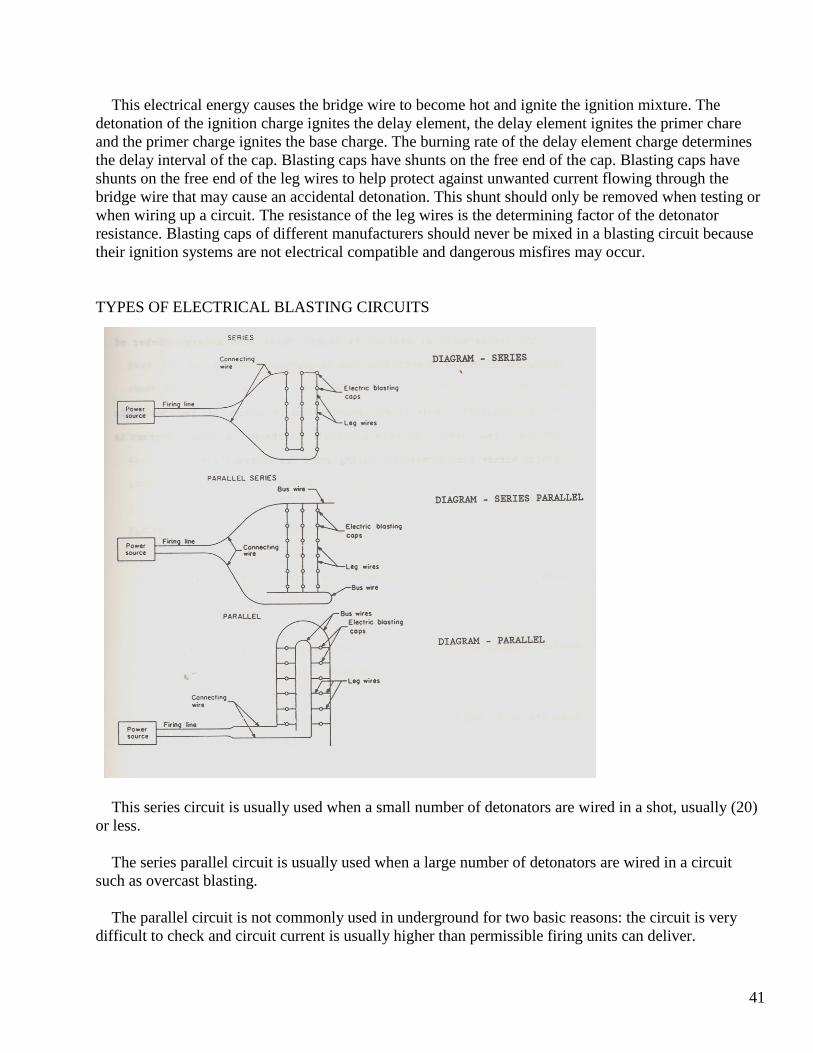
41
This electrical energy causes the bridge wire to become hot and ignite the ignition mixture. The detonation of the ignition charge ignites the delay element, the delay element ignites the primer chare and the primer charge ignites the base charge. The burning rate of the delay element charge determines the delay interval of the cap. Blasting caps have shunts on the free end of the cap. Blasting caps have shunts on the free end of the leg wires to help protect against unwanted current flowing through the bridge wire that may cause an accidental detonation. This shunt should only be removed when testing or when wiring up a circuit. The resistance of the leg wires is the determining factor of the detonator resistance. Blasting caps of different manufacturers should never be mixed in a blasting circuit because their ignition systems are not electrical compatible and dangerous misfires may occur. TYPES OF ELECTRICAL BLASTING CIRCUITS
This series circuit is usually used when a small number of detonators are wired in a shot, usually (20) or less. The series parallel circuit is usually used when a large number of detonators are wired in a circuit such as overcast blasting. The parallel circuit is not commonly used in underground for two basic reasons: the circuit is very difficult to check and circuit current is usually higher than permissible firing units can deliver.
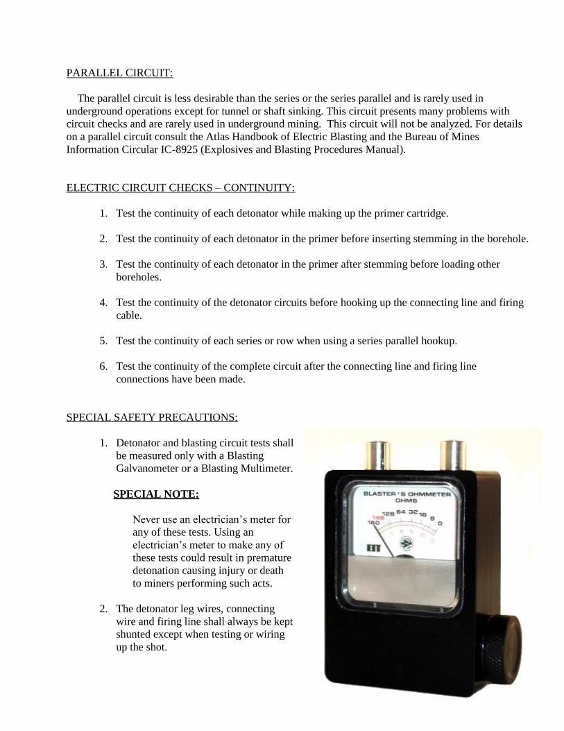
42
PARALLEL CIRCUIT: The parallel circuit is less desirable than the series or the series parallel and is rarely used in underground operations except for tunnel or shaft sinking. This circuit presents many problems with circuit checks and are rarely used in underground mining. This circuit will not be analyzed. For details on a parallel circuit consult the Atlas Handbook of Electric Blasting and the Bureau of Mines Information Circular IC-8925 (Explosives and Blasting Procedures Manual). ELECTRIC CIRCUIT CHECKS – CONTINUITY:
1. Test the continuity of each detonator while making up the primer cartridge.
2. Test the continuity of each detonator in the primer before inserting stemming in the borehole.
3. Test the continuity of each detonator in the primer after stemming before loading other boreholes.
4. Test the continuity of the detonator circuits before hooking up the connecting line and firing
cable.
5. Test the continuity of each series or row when using a series parallel hookup.
6. Test the continuity of the complete circuit after the connecting line and firing line connections have been made.
SPECIAL SAFETY PRECAUTIONS:
1. Detonator and blasting circuit tests shall be measured only with a Blasting Galvanometer or a Blasting Multimeter.
SPECIAL NOTE:
Never use an electrician’s meter for any of these tests. Using an electrician’s meter to make any of these tests could result in premature detonation causing injury or death to miners performing such acts.
2. The detonator leg wires, connecting wire and firing line shall always be kept shunted except when testing or wiring up the shot.
43
3. The detonator leg wires, connecting wire and firing line (blasting cable) splices shall be away from contact with water, face, ribs, and mine floor to prevent accidental detonation by stray current.
4. The blasting cable should always be inspected for any bad splices, defects and faulty
insulation areas before wiring to any shot.
5. The leg wires, connecting line (when applicable) and firing line (blasting cable) connections should be made unrolling toward the location from which the shot will be fired.
6. A final methane check shall be made before wiring in the connecting line (when applicable)
and the blasting cable. If methane is detected in concentrations of 1 percent or more, ventilation corrections must be made to reduce the gas to less than 1 percent.
FIRING
Special attention shall be made to ensure that all persons are cleared from the shot and adjacent areas, in a safe location and out of the line of blast. All persons shall be removed from the working place and the immediately adjoining working places to a distance of at least 100 feet. All persons shall be accounted for in the work area before shots are fired. Ample warning shall be given before any shot is fired such as fire – pause – fire – pause – fire. After ample warning has been given, connect the firing line – shooting cable to the blasting machine and fire the shot. After firing the shot, disconnect the firing line from the blasting machine and re-shunt the wires of the shooting cable.
44
POST BLAST INSPECTION
Always allow a reasonable amount of time for the dense smoke, dust and fumes to clear before returning to the shot area. It is very important to allow time for toxic gases to be cleared by ventilation before miners are allowed to re-enter the shot area. Smoke and dust can obscure the miner’s vision to the extent that he may not recognize dangerous roof or rib conditions and falling hazards. Miners rushing back into this low visibility area may injure themselves by falling over broken material in addition to the toxic fumes environment. Rushing to see the results of any shot area may be hazardous and possibly fatal. Fumes, produced by blasting are increased by insufficient confinement, damaged or deteriorated explosives and inadequately primed explosives. The most toxic gases produced are carbon monoxide and oxides of nitrogen. A thorough roof and rib inspection must be made to ensure loose rock or coal is not present that could cause an accident. This inspection shall only be made after the smoke, dust and fumes have cleared and good visibility is present. A final gas check shall be made to ensure a possible accumulation of methane is not present that could have resulted from the shot. A thorough inspection of the blast area shall be conducted to check for any undetonated explosive, visible leg wires and any boreholes which may have misfired. A continuity check should be made on any visible leg wires with an approved galvanometer. A positive continuity check will reveal that the detonator has not fired or the wires are in contact.
45
MISFIRES
A misfire is defined as the failure of an explosive charge to detonate at the proper time. Any misfired hole, portions of misfired holes or undetonated explosive materials that remain after a blast is fired presents an extremely hazardous situation that will exist until the misfired explosive materials have been disposed of properly. Explosive disposal requires sound judgment and a comprehensive understanding of explosives by the shot firer and mine foreman in charge. Most misfires occur because of improper techniques used by the shot firer or a change in the blasting structure from the norm. Proper methods of preparing primers, priming, loading, stemming, wiring and firing will greatly decrease the likehood of a misfire. The best advice that can be given regarding the handling of misfires is to take every precaution to prevent their occurrence. Because every misfire is a potential hazard, the safest way to handle a misfire is to prevent it. However, if a misfire does occur, a shot firer must know how to handle it safely. Specific recommendations concerning misfire handling procedures cannot be made, as every misfire must be evaluated on an individual basis. There are so many different conditions involved in misfires that it is virtually impossible to offer specific, detailed instructions covering all of the situations that may arise. All information regarding a misfire must be analyzed completely and a plan of action outlined to safely handle, neutralize and dispose of the explosives involved. State and Federal regulations and explosive manufacturer recommendations governing the handling of misfires must be followed. Specific instructions for handling misfires is impossible to issue because of variations in explosives, methods of blasting and individual shot area analysis. A shot firer must bear in mind that all work in or near a misfired hole or shot area is a most hazardous operation. Drilling or digging into material containing unexploded explosives is extremely dangerous. Extreme caution and shot circuit analysis must be exercised while evaluating a misfire to reduce the chances of a potential disaster. Sources of Misfires: Thorough investigation of a misfire will usually determine its cause. Some of the more frequent causes of misfires are:
1. Improperly made primers 2. Improper loading practices 3. Damage to detonator leg wires 4. Failure to connect detonator leg wires into the circuit 5. Insufficient electrical current to detonate the shot Always trace the cause of a misfire and take the necessary corrective action to prevent future misfires.
46
PREVENTING MISFIRES: The best way to prevent a misfire is to become thoroughly familiar with the causes and follow good blasting practices. Common causes of misfires are listed below with the corrective action for each: CAUSE CORRECTIVE ACTION Poor wire connections Clean corrosion, dirt and insulation off the wire
ends before making connections. Make strong, secure connections.
Bare splices in water Keep all bare wires out of water and away from wet
areas. Improper detonator circuit When using a series-parallel circuit, the resistance
of the individual series should be the same or nearly the same within plus or minus 2 ohms.
Current leakage Check for current leakage and reduce the number of
detonators per series. Visually inspect the firing circuit and ensure that all the detonators are wired into the circuit.
Only explosive materials from the same
manufacturer should be used in the same blasting circuit.
The blasting cable shall have good insulation. The
size of the blasting cable should be large enough to allow the power source being used to deliver adequate firing energy to the detonator circuit.
Inadequate Power Source The blasting machine energy should be checked
following prescribed manufacturer recommendations.
HANDLING A MISFIRE:
Specific recommendations and procedures concerning misfires cannot be made because every misfire must be evaluated on an individual basis.
The handling of a misfire shall be under the direct supervision of the mine foreman or a competent
person designated by the mine foreman.
Mixing Explosive Materials From Different Manufacturers
Defective or Inadequate Firing Line (blasting cable)

47
These general safety precautions shall be taken into consideration when handling a misfire:
Do not allow any unnecessary personnel to return to the shot area. Most explosives manufacturers recommend from 15 minutes to a 1 hour waiting period before returning to the shot area. The shot firer and the mine foreman in charge should maintain accountability of all miners in this work area and be certain that the shot area is not approached by any unauthorized miner from any direction except those designated miners assigned to investigate the misfire.
Disconnect the shooting cable from the firing agent or power source and shunt the ends of the
shooting cable. Always be absolutely certain that the shooting cable is disconnected from the firing agent before re-entering a misfired shot area.
After an appropriate waiting period, the shot area will have to be inspected by the shot firer,
mine foreman or other competent person designated by the mine foreman. Another individual, knowledgeable in misfire disposal should act as a safety back-up for the person or persons investigating the misfire. This safety back-up person should remain out of the shot area but observe the situation from a safe distance.
Do not start any other work in the area of the misfire except that undertaken to remove the
misfire hazard.
Investigate and correct the misfire with experienced personnel who would be allowed to work in a methodical manner and without interference. All observable system components should be identified and recorded.
Carefully examine the shot area and the immediate area to determine how many boreholes
and how much explosives misfired. If there is any suspicion of unfired detonators or explosive materials they should be treated as though they are live. The condition of the shot area should be determined. A slow, cautious and thorough evaluation must be made when re-entering a misfired shot area in order to detect any unsafe, unstable, dangerous roof or rib conditions. All undetonated explosives lying in the shot area should be picked up and stored properly while awaiting being destroyed in accordance with manufacturers guidelines.
After this attempt to re-fire the misfired hole or misfired shot, explosive manufacturers have
recommended not returning to the shot area for at least one hour when water was used to remove the stemming.
Under most conditions the safest way to dispose of a misfire is to be able to reconnect all the
unfired charges and fire them successfully. This procedure is not always possible or practical, as often the misfired charges have displaced the material being blasted. If the cap leg wires in the missed hole or shot area are accessible, test the circuit with a blasting galvanometer or blasting multimeter.
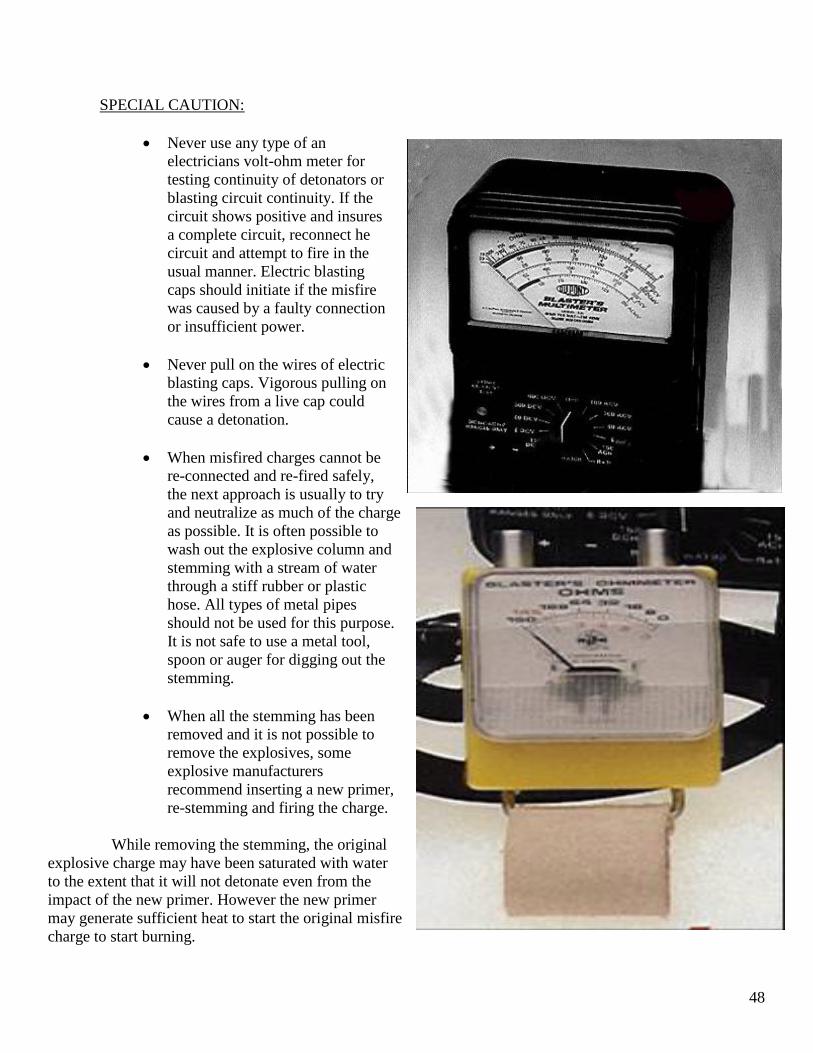
48
SPECIAL CAUTION:
Never use any type of an electricians volt-ohm meter for testing continuity of detonators or blasting circuit continuity. If the circuit shows positive and insures a complete circuit, reconnect he circuit and attempt to fire in the usual manner. Electric blasting caps should initiate if the misfire was caused by a faulty connection or insufficient power.
Never pull on the wires of electric
blasting caps. Vigorous pulling on the wires from a live cap could cause a detonation.
When misfired charges cannot be
re-connected and re-fired safely, the next approach is usually to try and neutralize as much of the charge as possible. It is often possible to wash out the explosive column and stemming with a stream of water through a stiff rubber or plastic hose. All types of metal pipes should not be used for this purpose. It is not safe to use a metal tool, spoon or auger for digging out the stemming.
When all the stemming has been
removed and it is not possible to remove the explosives, some explosive manufacturers recommend inserting a new primer, re-stemming and firing the charge.
While removing the stemming, the original explosive charge may have been saturated with water to the extent that it will not detonate even from the impact of the new primer. However the new primer may generate sufficient heat to start the original misfire charge to start burning.

49
This will result in a dangerous “Hangfire”. The sound of the reprimed charge firing is not a dependable indication that it is safe to return to the blast area before the manufacturers recommended one (1) hour waiting period. Explosive manufacturers recommend that when repriming and refiring the misfire cannot be accomplished, the least dangerous method is to attempt to remove the explosives from the borehole with water. When it is impossible to reinitiate, retrieve or neutralize misfired explosives, it may necessary to consider drilling, loading, and firing or boreholes that are adjacent to the misfired hole. SPECIAL SAFETY NOTE: Such drilling adjacent to a misfired borehole should be considered only as a last resort after all other courses of action have failed and only after consulting with the explosives manufacturer for information, recommendations and assistance. The drilling, loading, stemming and firing of boreholes near holes containing misfired explosive materials is an extremely hazardous task that should only be undertaken by experienced, competent personnel utilizing extreme caution and care. The borehole location must be exact and the redrilling operation monitored constantly. Every precaution must be taken to ensure that the drill bit will not intersect any explosive charge. Explosive boreholes that are drilled adjacent to a misfired hole shall be drilled two feet away from and parallel to the misfired charge. After the holes adjacent to the misfires have been fired, a thorough inspection should be made of the blasted material for any displaced and unfired explosive materials. As the blasted material is removed, it must be inspected continuously by experienced personnel to make sure that all misfired explosive materials are detected and removed for manufacturer recommended disposal. An unresolved misfire indicates that the hazard remains and is an extreme danger to all personnel and equipment. It must be emphasized that misfires, the disposal of misfires and the working of personnel or equipment in areas where misfires are present is extremely hazardous. Only competent, experienced personnel should be instructed to handle misfires. In situations where there is any doubt or question regarding the properties of explosive materials and detonators that were used in a misfired shot, the manufacturer should be consulted for information, recommendations and assistance. Misfired explosives should never be re-used under any circumstances. SPECIAL SAFETY NOTE: If the shot firer follows the proper methods of preparing primers, priming, loading, stemming, wiring, and firing, the likelihood of a misfire is extremely small. Good blasting practices in conjunction with permissible explosives used in a permissible manner will aid in reducing the risk of a misfire.

50
The sources listed below can be referenced for additional safety precautions when handling misfires:
1. ISEE Blasters Handbook 2. Atlas Handbook of Electric Blasting 3. Institute Makers of Explosives Publication Number 17 Safety in the Transportation, Storage,
Handling and Use of Explosives Materials
51
GOOD BLASTING PRACTICES
Good blasting practices are necessary requirements for all safe and efficient shot firers. A review of some good blasting practices will help to ensure that explosive shots are wired and fired in the safest and most efficient manner. SPLICES: The reliability of every blasting circuit is dependent on the number and quality of wiring splices in that circuit. Any blasting circuit is only as reliable as the weakest connection in that circuit. Circuit connections are just as important as any other factor in good blasting practices. The twisted loop splice is recommended for joining light gauge wires of similar size (leg wires to leg wires or leg wires to connection line). This splice is easy, quick to make, yet strong and reliable. It is a highly visible splice that is easy to disassemble if a circuit has to be taken apart for any reason. When joining lighter gauge leg wires or connecting wire to heavier gauge firing line (shooting cable), the lighter gauge wire is wrapped around the heavier gauge wire. These splices are easy to make and provide a strong reliable connection. To prevent current leakage or the shorting out of the two wires, the bare wire at the splices should be insulated with electrical tape. If insulating tape is not available, support the splices in the air by propping up the wire on boxes or dry cardboard and stagger their location such that they cannot accidentally short out. Splices in wiring connections should never be allowed to touch the mine roof, floor, ribs or allowed to be placed in water. The need to make a strong splice to keep the wire connections from pulling apart is a vital part of wiring any underground shot. One way to keep connections from pulling apart is to join the insulated portion of the wires about 4 inches back from the splice by tying or twisting them together. This secondary connection will absorb any strain induced into the wire and prevent separation of the splices. It would now be easier to position a bare wire splice so that it is off he mine floor or rib, thus reducing the chance of current leakage. SERIES BALANCING: Blasting circuits that contain only a small number of detonators are normally connected in a straight series or simple series circuit. Most series circuits used underground will not usually contain more than 20 detonators. When a high number of detonators are used, a series-parallel circuit should be used. All series should be equally divided when using a series-parallel circuit so that each series has the same resistance to within plus or minus 2 ohms. This series balancing will ensure that the firing current is equally divided and capable of firing the complete shot. FIRING LINE (SHOOTING CABLE) RESISTANCE: The resistance of the shooting cable is an important factor in determining how much firing current will be delivered to the detonator circuit. The shooting cable should be large enough to supply ample firing
52
current and should be compatible with the total circuit resistance such that the firing unit or power source can supply sufficient current to detonate the shot. CONNECTING LINE USE: In large series-parallel blasts, connecting wire is often used to connect the ends of the individual series to the shooting cable. Connecting wires is also used to connect detonator leg wires to the shooting cable. To help ensure equal distribution of firing current to all detonators in a series-parallel circuit, a reverse hook-up between the shooting cable and connecting wire is recommended by explosive manufacturers. This reverse hookup consists of connecting the shooting cable to opposite ends of the connecting wires. The resistance of connecting wire is very important since it serves as extensions of the shooting cable. The resistance of the connecting wire and shooting cable should be compatible with the total circuit resistance such that the firing unit or power source can supply ample firing current through the total circuit to detonate the shot. CHECKING A BLASTING CIRCUIT: Sufficient time should be allowed after the circuit is wired up and before firing the blast to check the blasting circuit. Two types of checks should be made:
1. Visual check 2. Electrical check
VISUAL CHECK: The visual check is made by walking the shot while tracing each series and circuits to make sure that all detonators have been connected into the circuit, that all splices are intact, out of water, insulated from roof, ribs and mine floor and that all unused explosives have been removed from the blast area. Only a limited number of authorized, competent miners should be allowed to walk the shot to ensure that circuit wiring is not broken during the inspection. ELECTRICAL CHECK: The electrical check is made in steps to ensure that the blasting circuit is properly wired.
1. The resistance and continuity of each detonator should be checked using a blasting galvanometer before it is assembled into a primer, checked again before the stemming is inserted and after stemming before any other boreholes are loaded.
53
SPECIAL SAFETY PRECAUTION: Absolutely, never use an electrician’s volt-ohm meter to check blasting caps or any blasting circuit. A detonator that shows an open circuit should never be used.
2. Each series of detonators should be checked to be sure that the resistance is as calculated, that the series are balanced and all have about the same resistance. In blasts containing more than one series, the total resistance of a series-parallel circuit will always be less than the resistance of just one of the series. For example, if there are four series in a series parallel blast and each series has a resistance of 80 ohms, the series parallel resistance will decrease as follows: 1 Series – 80 ohms, 2 Series – 40 ohms, 3 Series – 26.7 ohms, 4 Series – 20- ohms.
3. The shooting cable should be checked for an open or short circuit before it is connected to
the detonator circuit. Connect the two conductors at one end of the firing line, then open and touch the two conductors at the opposite end of the firing line to the terminals of a blasting galvanometer. When the free end of the conductors are together, the blasting galvanometer should indicate a resistance equal to that of the line being tested; when the free end is open or separated, the blasting galvanometer should indicate infinite ohms. If the measured resistance when the conductors are together is either high, low, unstable or if an indication other than infinite ohms is obtained while the conductors are separated, the shooting cable should not be used until it is inspected for damage, defective insulation, damaged or broken conductors and the necessary repairs have been made.
SPECIAL SAFETY PRECAUTION: If the shooting cable cannot be repaired or if there is any question concerning its quality, it should be discarded and a new shooting cable acquired. The shooting cable should be inspected and checked for continuity-resistance, before each use to ensure the highest of quality performance. CURRENT LEAKAGE: When electric detonators are wired into a circuit with adequate firing current supplied but some of the detonators fail to fire, the chances are good that part of the circuit current bypassed the unfired detonators. Bare splices that touch the roof, ribs, mine floor, water or damaged leg wire insulation provide a means for part of the firing current to leave the circuit and travel through the earth. Tests have shown that generally the detonators that misfire will be located in the middle of a series. These detonators misfire because the current they receive is not sufficient to activate their ignition system before other detonators that receive a higher firing current detonate and break the circuit. Some of the conditions that are likely to contribute to current leakage are as follows:
1. Ragged boreholes that damage leg wire insulation
2. Wet or damp areas
54
3. Highly conductive layers in the earth
4. Water in a borehole
5. Failure to insulate wire at splices from the earth or from each other
When one or more of the above conditions present a current leakage problem, a current leakage test should be made in accordance with explosive manufacturer guidelines. POWER LINE SHOOTING: Power line shooting is occasionally used underground when firing a large number of detonators when a permissible firing unit cannot supply ample current to fire the shot. Special permission must be obtained from MSHA and the Chief, Division of Mines to fire any shot that cannot be fired with a permissible firing unit. Power line shooting is a satisfactory source of firing current provided some main factors are taken into consideration.
1. That there is adequate power to fire the shot
2. That detonator “Arcing” is prevented The power source must be capable to supply sufficient power to fire the shot. A shot firer should identify that according to the total circuit resistance, the power line can supply ample current to fire the shot. When a small number of detonators are fired at one time, special precautions must be followed to prevent detonator “arcing”. “Arcing” occurs when too high a current is applied to a detonator for too long a time. Arcing was covered in another section of this study guide and does not warrant further discussion here.
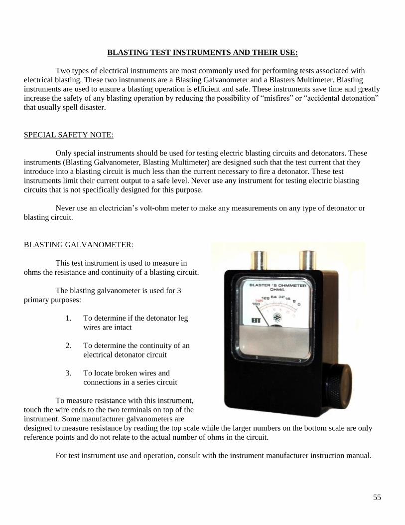
55
BLASTING TEST INSTRUMENTS AND THEIR USE:
Two types of electrical instruments are most commonly used for performing tests associated with electrical blasting. These two instruments are a Blasting Galvanometer and a Blasters Multimeter. Blasting instruments are used to ensure a blasting operation is efficient and safe. These instruments save time and greatly increase the safety of any blasting operation by reducing the possibility of “misfires” or “accidental detonation” that usually spell disaster. SPECIAL SAFETY NOTE: Only special instruments should be used for testing electric blasting circuits and detonators. These instruments (Blasting Galvanometer, Blasting Multimeter) are designed such that the test current that they introduce into a blasting circuit is much less than the current necessary to fire a detonator. These test instruments limit their current output to a safe level. Never use any instrument for testing electric blasting circuits that is not specifically designed for this purpose. Never use an electrician’s volt-ohm meter to make any measurements on any type of detonator or blasting circuit. BLASTING GALVANOMETER: This test instrument is used to measure in ohms the resistance and continuity of a blasting circuit. The blasting galvanometer is used for 3 primary purposes:
1. To determine if the detonator leg wires are intact
2. To determine the continuity of an
electrical detonator circuit
3. To locate broken wires and connections in a series circuit
To measure resistance with this instrument, touch the wire ends to the two terminals on top of the instrument. Some manufacturer galvanometers are designed to measure resistance by reading the top scale while the larger numbers on the bottom scale are only reference points and do not relate to the actual number of ohms in the circuit. For test instrument use and operation, consult with the instrument manufacturer instruction manual.

56
SPECIAL SAFETY PRECAUTION: Only special silver chloride batteries should be used to power the Blasting Galvanometer. When a battery is exhausted, it must be replaced with the same type of silver chloride battery. Shot firers should use only manufacturer recommended batteries in this and all other test instruments. Other batteries produce a hazardous current level that could detonate an electric blasting cap or a complete blasting circuit. Never test an electric blasting cap or blasting circuit directly with a battery. Never change batteries in the vicinity of electric blasting caps. Never allow a silver chloride battery or any other battery to come in direct contact with electric blasting caps or any blasting circuit. Never use any battery in a Blasting Galvanometer other than a silver chloride type or other type as specified by the instrument manufacturer. The silver chloride battery or other instrument manufacturer recommended battery should be replaced when the instrument cannot be adjusted to a zero-ohm reading. BLASTING MULTIMETER:
This test instrument is a multi-purpose instrument used for making voltage and resistance measurements. Some multimeters also measure current. A selector switch on the front of the meter case is turned to the desired function reading: voltage, current or resistance. Manufacturer instruction manuals provide operation and testing guidelines. Special current limiting circuitry in these instruments ensures that the test current introduced into the blasting circuit is much less than the amount required to ignite an electric detonator or detonator circuit. Manufacturer multimeter instruction manuals should be referenced to determine meter operation and limitations. Blasting Multimeters are designed to perform tests such as:
1. Blasting machine output voltage
2. AC and DC power line voltage

57
3. Electric detonator and blasting circuit resistance
4. “Opens” or “shorts” in any wiring circuit; detonators, connecting line, shooting cable, etc.
5. Current leakage
6. AC and DC stray current
For detailed information on field use for all testing instruments, refer to the manufacturer instruction manual.
OVERCAST BLASTING: Overcast shooting will usually require variations that are somewhat different from other types of underground blasting. Some major differences between overcast shooting and routine blasting underground are:
1. A large number of boreholes will be used
2. A series-parallel circuit is most commonly used to accommodate the large number of detonators
3. Special permission must be granted by MSHA and the Chief, Division of Mines to use a
nonpermissible shot firing unit that is sometimes necessary to fire such a large number of detonators. MSHA will also issue a permit, obtained through request, allowing the use of a nonpermissible firing unit. This permit will also list other safe guards that must be followed in addition to State and Federal Law. The MSHA permit would apply only to the blasting of overcasts and would be subject to revocation if the requirements are violated. This permit will specifically identify the requirements when shooting a large overcast shot.
Listed below are some particular safe guards that is usually required as part of the MSHA permit. This list is shown only as an example. The permit will identify the specific requirements:
1. The location of the shot shall be fire-bossed, both before and after the shot. A thorough inspection of the roof and ribs should be maintained throughout the blasting procedure.
2. The area shall be cleaned and well rock-dusted before the charge is fired.
3. Proper ventilation shall be provided. Sufficient air flow should be present in the shot area.
4. Proper breaker timbers shall be set. Eight breaker timbers or more are usually set in each
entry to the shot area.

58
5. Drilling procedures are dependent upon coal height, overcast clearance and travel clearance.
6. The primer cartridge shall be the first cartridge inserted into the borehole.
Delay detonators shall be limited to those of one manufacturer. The delay intervals between succeeding holes and maximum time interval for the complete shot will be specified in the permit. Other detonator requirements and limitations may be specified in the permit. A pattern of the boreholes, delay intervals, series resistance and total circuit resistance will also be specified in the permit. A maximum amount of explosives per borehole and for the complete shot will be specified in the permit.
7. The stemming procedure will usually be specified in the permit. If not specified, boreholes
over 4 feet in depth shall be stemmed with 24 inches of inert material, while boreholes less than 4 feet in depth shall be stemmed to at least one-half the depth of the hole.
8. All blasting circuits and detonators shall be tested for resistance and continuity with a
blasting galvanometer.
9. A methane test should be conducted before detonator leg wires are connected.
10. No miners or other persons shall be located inby the blast area.
11. Blasting cable requirements:
a. Well insulated, without splices, not less than number 16 gauge copper. b. Not less than 250 feet in length and as long as necessary to permit the shot firer to be in a
safe location.
c. Well separated when connected to the detonator leg wires.
d. Ends shall be clean and securely connected.
e. Bare connections shall be kept out of water, free of contact with coal, roof, ribs and mine floor.
f. Shunted until ready to attach to the blasting unit and rolled out toward the blasting unit.
12. The shot firing unit shall have adequate capacity to fire all charges in the shot. The type,
description, capacity and limitations of the blasting unit will usually be specified in the permit.
13. The shot will take place when the mine has been evacuated of all non-essential personnel.
14. Essential personnel shall consist of one certified mine foreman and a certified shot firer.

59
15. An adequate warning shall be sounded before firing the shot.
16. After making warning calls, hook the blasting cable to the blasting machine and fire that shot.
17. Disconnect the shooting cable and shunt the ends after firing the shot.
18. Allow smoke and fumes to clear before anyone returns to the shot area.
19. Upon returning to the shot area: inspect the roof and ribs, make a methane check and check
the ventilation. NOTE: These safeguards were only used as an example to give a shot firer a brief understanding of some of the requirements of a permit required to shoot an overcast when a non-permissible firing unit must be used to fire the shot. Specific safeguards, procedures and requirements will be listed in the permit. All handling, transportation, storage, and use of permissible explosives and detonators shall be performed as recommended by the explosive manufacturer and as required by STATE AND FEDERAL LAW, unless otherwise directed by the permit.

60
Practical’s
Example of shooting from solid plan
61
CONDITIONS AND LIMITATIONS
The following conditions and limitations are prescribed to be incorporated as a part of the solid shooting permit for: Company: Ocean Mining, Inc. Mine Name: Sun Rise Mine No. 1 Mine Index No: 12345AA MSHA I.D.: 44-01234
1. All sections of the Coal Mine Safety Laws of Virginia pertaining to explosives and blasting must be complied with.
2. A proper gas test must be made immediately before shot holes are charged.
3. The face area must be adequately rock dusted prior to the detonation of charged holes.
4. Breaker holes must be provided for any face where coal is blasted from the solid and must be the
first hole fired in any face.
5. Explosives may not be transported from the section magazine to the faces in the original shipping container. This applies whether the original container is opened or unopened, transported in wagons or carried. They can be transported in powder bags.
6. Explosives must be detonated with a permissible shot-firing unit. Special permission must be
obtained for the use of other appropriate shot-firing devices.
7. Explosives shall not be fired when the temperature of the explosive is below the manufacturers’ recommended minimum firing temperature.
8. Mixed explosives or detonators shall not be used in a single blasting operation.
9. All shot holes must be adequately cleaned before the explosives are inserted in the hole.
10. When charging a shot hole, the explosive cartridge containing the detonator shall be the first
cartridge inserted in the mouth of the hole. The additional cartridges of explosives are to be placed in the hole against the primed cartridge and pushed in a continuous train toward the back of the hole.
11. The cutting of an explosive cartridge to permit the use of a piece of a cartridge in a shot hole is
not considered to be deforming the explosives. Any cutting or slitting for other than the above use will be considered to be deliberately deforming the explosives and is prohibited.
12. Only stemming of a non-combustible clay substance, or comparable product, may be used in solid
shooting in order to ensure proper deformation of the stemming material. Frozen, dried out or otherwise hardened clay stemming shall not be used.
62
13. All shot holes must be stemmed with at least 24 inches of incombustible material, or at least one-half the length of the hole to be stemmed if the depth of the shot hole is less than four feet.
14. When stemming a shot hole, the first dummy is to be inserted against the explosive charge and
tamped very lightly. The succeeding dummies are to be placed into the hole individually and tamped individually until they are expanded to cover the entire circumference of the shot hole and are tightly compacted.
15. The minimum delay period between any two adjacent shot holes (either vertically or horizontally
adjacent) shall not be less than 50 milli-seconds. The maximum shall not be more than 100 milli-seconds.
16. The maximum delay period between the first and the last shot in any one blasting operation shall
not exceed 1,000 milli-seconds.
17. Not more than one face may be blasted at any one time.
18. Two faces directly across from each other may be charged and prepared to fire as long as the leg wires in the completed face are shunted while the other face is being charged.
19. All electric equipment inby the last open crosscut in the working place shall be removed or de-
energized before any holes are charged in the working place and shall remain so until the shots are fired.
Sincerely, _____________________________________________ Company Official

63
EXPLOSIVE/DETONATOR DATA
The following information is hereby incorporated as part of the solid shooting permit for: Company Name: Ocean Mining, Inc.
Mine Name: Sun Rise Mine No. 1
Mine Index No: 12345AA MSHA I.D.: 44-01234 and is accepted accurate and correct and should not be deviated from while this permit is in effect. NOTE: Should any of this information change, this office should be contacted immediately. Explosive Manufacturer: Austin Powder Company Type: Red Diamond, Atlas, 7D, ICI, 8S, 5U, etc. Size: 1 ¼” x 12” – 1 ¼” x 24” Maximum number of sticks of explosives per hole: 4 Detonator Manufacturer: Austin Powder Company Type: Coal Mine Delays Delay numbers: 1-6 Shot-firing Unit Shot-firing Unit Manufacturer: Femco, Scorpion HD Shot-firing Unit Model: SF25-20 and HB-20P, 20 shot
64
EXPLOSIVE/DETONATOR DATA
The following information is hereby incorporated as part of the solid shooting permit for: Company: Ocean Mining, Inc.
Mine Name: Sun Rise Mine No.1
Mine Index No: 12345AA MSHA I.D.: 44-01234 and is accepted accurate and correct and should not be deviated from while this permit is in effect. NOTE: Should any of this information change, this office should be contacted immediately. Explosive Manufacturer: AUSTIN POWDER C0. Type: COALMEX, RED DIAMOND, ETC. Size: 1 ¼” X 16” Maximum number of sticks of explosives per hole: 4 Detonator Manufacturer: AUSTIN POWDER CO. Type: COAL MINE DELAYS Delay numbers: 1 - 6 Shot-firing Unit Shot-firing Unit Manufacturer: IDEAL SUPPLY CO. FEMCO SCORPION HD Shot-firing Unit Model: HCCR, SF25-20 and HB-20P, 20 shot

65
EXPLOSIVE/DETONATOR DATA
The following information is hereby incorporated as part of the solid shooting permit for: Company: Ocean Mining, Inc.
Mine Name: Sun Rise Mine No. 1
Mine Index No: 12345AA MSHA I.D.: 44-01234 and is accepted accurate and correct and should not be deviated from while this permit is in effect. NOTE: Should any of this information change, this office should be contacted immediately. Explosive Manufacturer: DYNO-NOBEL. Type: Z-POWDER Size: 1 ¼” X 16” Maximum number of sticks of explosives per hole: 4 Detonator Manufacturer: DYNO-NOBEL Type: COAL MINE DELAYS Delay numbers: 1 - 6 Shot-firing Unit Shot-firing Unit Manufacturer: IDEAL SUPPLY CO. FEMCO SCORPION HD Shot-firing Unit Model: HCCR, SF25-20 and HB-20P, 20 shot
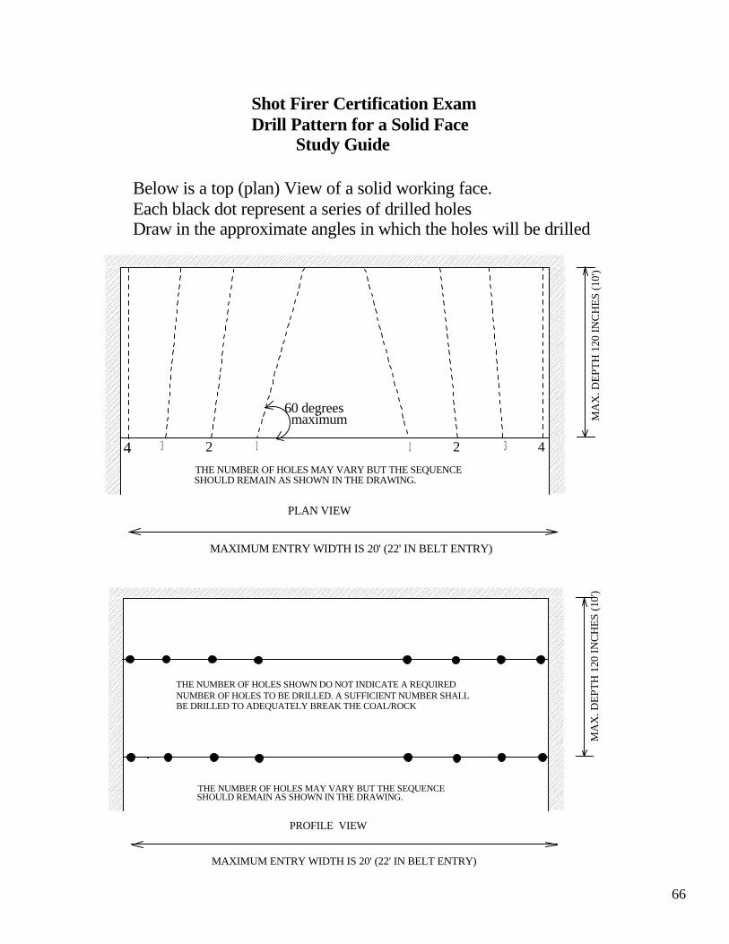
66
Shot Firer Certification ExamDrill Pattern for a Solid Face Study Guide
Below is a top (plan) View of a solid working face.Each black dot represent a series of drilled holesDraw in the approximate angles in which the holes will be drilled
PLAN VIEW
4 3 2 1 1 2 3 4
60 degreesmaximum M
AX
. DEP
TH 1
20 IN
CH
ES (1
0')
THE NUMBER OF HOLES MAY VARY BUT THE SEQUENCESHOULD REMAIN AS SHOWN IN THE DRAWING.
MAXIMUM ENTRY WIDTH IS 20' (22' IN BELT ENTRY)
PROFILE VIEW
MA
X. D
EPTH
120
INC
HES
(10'
)
THE NUMBER OF HOLES MAY VARY BUT THE SEQUENCESHOULD REMAIN AS SHOWN IN THE DRAWING.
MAXIMUM ENTRY WIDTH IS 20' (22' IN BELT ENTRY)
THE NUMBER OF HOLES SHOWN DO NOT INDICATE A REQUIREDNUMBER OF HOLES TO BE DRILLED. A SUFFICIENT NUMBER SHALLBE DRILLED TO ADEQUATELY BREAK THE COAL/ROCK
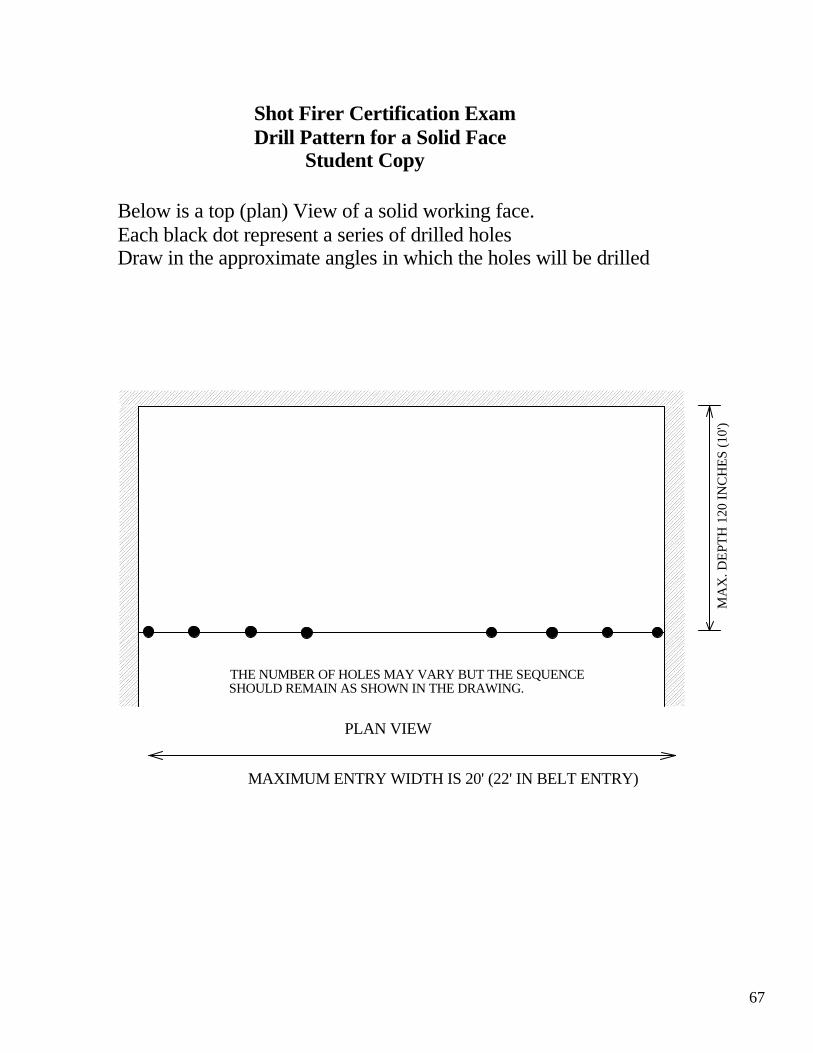
67
Shot Firer Certification ExamDrill Pattern for a Solid Face Student Copy
PLAN VIEWM
AX
. DEP
TH 1
20 IN
CH
ES (1
0')
THE NUMBER OF HOLES MAY VARY BUT THE SEQUENCESHOULD REMAIN AS SHOWN IN THE DRAWING.
MAXIMUM ENTRY WIDTH IS 20' (22' IN BELT ENTRY)
Below is a top (plan) View of a solid working face.Each black dot represent a series of drilled holesDraw in the approximate angles in which the holes will be drilled

68
Shot Firer Certification ExamDrill Pattern for a Solid Face Study Guide
PLAN VIEW
4 3 2 1 1 2 3 4
60 degreesmaximum M
AX
. DEP
TH 1
20 IN
CH
ES (1
0')
THE NUMBER OF HOLES MAY VARY BUT THE SEQUENCESHOULD REMAIN AS SHOWN IN THE DRAWING.
MAXIMUM ENTRY WIDTH IS 20' (22' IN BELT ENTRY)
Below is a top (plan) View of a solid working face.Each black dot represent a series of drilled holesDraw in the approximate angles in which the holes will be drilled

69
MA
X. D
EPTH
120
INC
HES
(10'
)
PROFILE VIEW
or
432114 3 2
DELAY SEQUENCEMAXIMUM ENTRY WIDTH IS 20' (22' IN BELT ENTRY)
MA
X. D
EPTH
120
INC
HES
(10'
)
PROFILE VIEW
432114 3 2
DELAY SEQUENCE
MAXIMUM ENTRY WIDTH IS 20' (22' IN BELT ENTRY)
DELAYS WILL BE AS DESCRIBED IN ITEMS15 AND 16 OF THE CONDITIONS AND LIMITATIONS SECTION OF THIS PLAN
1
1
1 1
1
1 2
2
22
2
23
3
3 3
3
34
4
4 4
4
4
4
4
4 4
4
43
3
33
3
3 2
2
2 2
2
21
1
11
1
1
Shot Firer Certification ExamWiring Diagram for Solid Face Study Guide
WIRING DIAGRAM
70
Date___________Name___________________
20'
20'
Shot Firer Certification ExamWiring Diagram for Overcast/BoomholeStudent Copy
Below is a profile view of a drilled overcast.Each black dot represents a drilled hole. The blank below each black dot represents blasting cap delay.Draw in a correct wiring diagram.Using 1 thru 7 as delay Numbers, label each blasting cap in the blank under each dot to recieve the best results from the shot.
71
20'
20'
LEAD WIRE
Shot Firer Certification Wiring Diagram for Overcast/BoomholeStudy Guide
1 1 1 1 1 1 1
1 1 1 1 1 1 1
2 2 2 2 2 2 2
2 2 2 2 2 2 2
3 3 3 3 3 3 3
3 3 3 3 3 3 3
4 4 4 4 4 4 4
4 4 4 4 4 4 4
5 5 5 5 5 5 5
5 5 5 5 5 5 5
6 6 6 6 6 6 6
6 6 6 6 6 6 6
7 7 7 7 7 7 7
7 7 7 7 7 7 7
72
The following references have been used to compile this study guide: 1. Mining Laws of Virginia
2. Code of Federal Regulations (30 CFR)
3. Institute Makers of Explosives, Publication Number 17 and 4
4. DuPont Blaster’s Handbook
5. Bureau of Mines Circular Number 7895, Special Precautions for Multiple Blasting in Coal Mines
6. Bureau of Mines Circular IC – 8925 (Explosives and Blasting Procedures Manual)
7. Atlas Handbook of Electric Blasting
8. Bureau of Alcohol, Tobacco, Firearms and Explosives Publication 5400


![JP 315 Barriers, Obstacles, and Mine Warfare for …11).pdfobstacles (including improvise d explosive devices [IEDs], mines, and other unexploded explosive ordnance [UXO]) and to conduct](https://static.fdocuments.in/doc/165x107/5f7dbd9994360303483d278e/jp-315-barriers-obstacles-and-mine-warfare-for-11pdf-obstacles-including-improvise.jpg)