VIPA SPEED7 Library...4.2.22 FC 21 - LEN - Length of a STRING variable 29 4.2.23 FC 22 - LIMIT 29...
99
OPL_SP7-LIB | SW90JS0MA V10.003 | Manual HB00 | OPL_SP7-LIB | SW90JS0MA V10.003 | en | 18-45 VIPA SPEED7 Library Block library - Standard www.vipa.com/en/service-support/manuals
Transcript of VIPA SPEED7 Library...4.2.22 FC 21 - LEN - Length of a STRING variable 29 4.2.23 FC 22 - LIMIT 29...

OPL_SP7-LIB | SW90JS0MA V10.003 | ManualHB00 | OPL_SP7-LIB | SW90JS0MA V10.003 | en | 18-45
VIPA SPEED7 Library
Block library - Standard
www.vipa.com/en/service-support/manuals

SW90JS0MA_000_OPL_SP7-LIB_Standard,3,EN - © 2018
VIPA GmbHOhmstr. 491074 HerzogenaurachTelephone: +49 9132 744-0Fax: +49 9132 744-1864Email: [email protected]: www.vipa.com

Table of contents1 General.................................................................................................................... 6
1.1 Copyright © VIPA GmbH ................................................................................. 61.2 About this manual............................................................................................. 7
2 Important notes...................................................................................................... 82.1 General............................................................................................................. 82.2 Internally used blocks....................................................................................... 8
3 Include library......................................................................................................... 93.1 Integration into Siemens SIMATIC Manager.................................................... 93.2 Integration into Siemens TIA Portal................................................................ 10
4 Standard................................................................................................................ 114.1 Converting...................................................................................................... 114.1.1 FB 80 - LEAD_LAG - Lead/Lag Algorithm................................................... 114.1.2 FC 93 - SEG - Seven Segment Decoder..................................................... 124.1.3 FC 94 - ATH - ASCII to Hex......................................................................... 134.1.4 FC 95 - HTA - Hex to ASCII......................................................................... 134.1.5 FC 96 - ENCO - Encode Binary Position..................................................... 144.1.6 FC 97 - DECO - Decode Binary Position..................................................... 144.1.7 FC 98 - BCDCPL - Tens Complement......................................................... 154.1.8 FC 99 - BITSUM - Sum Number of Bits....................................................... 154.1.9 FC 105 - SCALE - Scaling Values............................................................... 154.1.10 FC 106 - UNSCALE - Unscaling Values.................................................... 164.1.11 FC 108 - RLG_AA1 - Issue an Analog Value............................................. 174.1.12 FC 109 - RLG_AA2 - Write Analog Value 2............................................... 184.1.13 FC 110 - PER_ET1 - Read/Write Ext. Per. 1............................................. 194.1.14 FC 111 - PER_ET2 - Read/Write Ext. Per. 2............................................. 204.2 IEC.................................................................................................................. 214.2.1 Date and time as complex data types......................................................... 214.2.2 FC 1 - AD_DT_TM - Add duration to instant of time.................................... 214.2.3 FC 2 - CONCAT - Concatenate two STRING variables.............................. 214.2.4 FC 3 - D_TOD_DT - Combine DATE and TIME_OF_DAY.......................... 224.2.5 FC 4 - DELETE - Delete in a STRING variable........................................... 224.2.6 FC 5 - DI_STRNG - Convert DINT to STRING............................................ 234.2.7 FC 6 - DT_DATE - Extract DATE from DT................................................... 234.2.8 FC 7 - DT_DAY - Extract day of the week from DT..................................... 234.2.9 FC 8 - DT_TOD - Extract TIME_OF_DAY from DT..................................... 244.2.10 FC 9 - EQ_DT - Compare DT for equality................................................. 244.2.11 FC 10 - EQ_STRNG - Compare STRING for equal.................................. 244.2.12 FC 11 - FIND - Find in a STRING variable................................................ 254.2.13 FC 12 - GE_DT - Compare DT for greater than or equal.......................... 254.2.14 FC 13 - GE_STRNG - Compare STRING for greater than or equal.......... 254.2.15 FC 14 - GT_DT - Compare DT for greater than........................................ 264.2.16 FC 15 - GT_STRNG - Compare STRING for greater than........................ 264.2.17 FC 16 - I_STRNG - Convert INT to STRING............................................. 274.2.18 FC 17 - INSERT - Insert in a STRING variable......................................... 274.2.19 FC 18 - LE_DT - Compare DT for smaller than or equal........................... 274.2.20 FC 19 - LE_STRNG - Compare STRING for smaller then or equal.......... 284.2.21 FC 20 - LEFT - Left part of a STRING variable......................................... 28
VIPA SPEED7 Library Table of contents
HB00 | OPL_SP7-LIB | SW90JS0MA V10.003 | en | 18-45 3

4.2.22 FC 21 - LEN - Length of a STRING variable............................................. 294.2.23 FC 22 - LIMIT............................................................................................ 294.2.24 FC 23 - LT_DT - Compare DT for smaller than......................................... 294.2.25 FC 24 - LT_STRNG - Compare STRING for smaller................................. 304.2.26 FC 25 - MAX - Select maximum................................................................ 304.2.27 FC 26 - MID - Middle part of a STRING variable....................................... 314.2.28 FC 27 - MIN - Select minimum.................................................................. 314.2.29 FC 28 - NE_DT - Compare DT for unequal............................................... 324.2.30 FC 29 - NE_STRNG - Compare STRING for unequal.............................. 324.2.31 FC 30 - R_STRNG - Convert REAL to STRING........................................ 334.2.32 FC 31 - REPLACE - Replace in a STRING variable................................. 334.2.33 FC 32 - RIGHT - Right part of a STRING variable.................................... 344.2.34 FC 33 - S5TI_TIM - Convert S5TIME to TIME.......................................... 344.2.35 FC 34 - SB_DT_DT - Subtract two instants of time................................... 354.2.36 FC 35 - SB_DT_TM - Subtract a duration from a time.............................. 354.2.37 FC 36 - SEL - Binary selection.................................................................. 354.2.38 FC 37 - STRNG_DI - Convert STRING to DINT........................................ 364.2.39 FC 38 - STRNG_I - Convert STRING to INT............................................. 364.2.40 FC 39 - STRNG_R - Convert STRING to REAL........................................ 374.2.41 FC 40 - TIM_S5TI - Convert TIME to S5TIME.......................................... 374.3 IO.................................................................................................................... 374.3.1 FB 20 - GETIO - PROFIBUS/PROFINET read all Inputs............................ 374.3.2 FB 21 - SETIO - PROFIBUS/PROFINET write all Outputs......................... 384.3.3 FB 22 - GETIO_PART - PROFIBUS/PROFINET read a part of the
Inputs........................................................................................................... 384.3.4 FB 23 - SETIO_PART - PROFIBUS/PROFINET write a part of the Out-
puts.............................................................................................................. 404.4 S5 Converting................................................................................................. 414.4.1 FC 112 - Sine(x) - Sine................................................................................ 414.4.2 FC 113 - Cosine(x) - Cosine........................................................................ 424.4.3 FC 114 - Tangent(x) - Tangent..................................................................... 434.4.4 FC 115 - Cotangent(x) - Cotangent............................................................. 434.4.5 FC 116 - Arc Sine(x) - Arcussine................................................................. 444.4.6 FC 117 - Arc Cosine(x) - Arcuscosine......................................................... 454.4.7 FC 118 - Arc Tangent(x) - Arcustangent...................................................... 464.4.8 FC 119 - Arc Cotangent(x) - Arcuscotangent.............................................. 464.4.9 FC 120 - Naperian Logarithm In(x) - Naperian Logarithm........................... 474.4.10 FC 121 - Decimal Logarithm Ig(x) - Decimal Logarithm............................ 484.4.11 FC 122 - Gen. Logarithm to Base b - General Logarithm Iog (x) to base
b................................................................................................................. 484.4.12 FC 123 - E to Power n - E high n............................................................... 494.4.13 FC 124 - 10 to Power n - 10 high n........................................................... 504.4.14 FC 125 - ACCU 2 to Power ACCU 1 - ACCU 2 high ACCU 1................... 504.5 PID Control..................................................................................................... 514.5.1 FB 41 - CONT_C - Continuous control........................................................ 514.5.2 FB 42 - CONT_S - Step Control.................................................................. 574.5.3 FB 43 - PULSGEN - Pulse generation........................................................ 624.5.4 FB 58 - TCONT_CP - Continuous Temperature Control............................. 704.5.5 FB 59 - TCONT_S - Temperature Step Control........................................... 874.6 Time Functions............................................................................................... 94
VIPA SPEED7 LibraryTable of contents
HB00 | OPL_SP7-LIB | SW90JS0MA V10.003 | en | 18-45 4

4.6.1 UDT 60 - WS_RULES - Rule DB................................................................. 944.6.2 FC 61 - BT_LT - Convert base timer to local time....................................... 954.6.3 FC 62 - LT_BT - Convert local time to base time........................................ 964.6.4 FC 63 - S_LTINT - Set time interrupt in local time....................................... 97
VIPA SPEED7 Library Table of contents
HB00 | OPL_SP7-LIB | SW90JS0MA V10.003 | en | 18-45 5

1 General1.1 Copyright © VIPA GmbH
This document contains proprietary information of VIPA and is not to be disclosed or usedexcept in accordance with applicable agreements.
This material is protected by the copyright laws. It may not be reproduced, distributed, oraltered in any fashion by any entity (either internal or external to VIPA), except in accord-ance with applicable agreements, contracts or licensing, without the express written con-sent of VIPA and the business management owner of the material.
For permission to reproduce or distribute, please contact: VIPA, Gesellschaft für Visuali-sierung und Prozessautomatisierung mbH Ohmstraße 4, D-91074 Herzogenaurach, Ger-many
Tel.: +49 9132 744 -0
Fax.: +49 9132 744-1864
EMail: [email protected]
http://www.vipa.com
Every effort has been made to ensure that the information contained inthis document was complete and accurate at the time of publishing. Nev-ertheless, the authors retain the right to modify the information.
This customer document describes all the hardware units and functionsknown at the present time. Descriptions may be included for units whichare not present at the customer site. The exact scope of delivery isdescribed in the respective purchase contract.
Hereby, VIPA GmbH declares that the products and systems are in compliance with theessential requirements and other relevant provisions. Conformity is indicated by the CEmarking affixed to the product.
For more information regarding CE marking and Declaration of Conformity (DoC), pleasecontact your local VIPA customer service organization.
VIPA, SLIO, System 100V, System 200V, System 300V, System 300S, System 400V,System 500S and Commander Compact are registered trademarks of VIPA Gesellschaftfür Visualisierung und Prozessautomatisierung mbH.
SPEED7 is a registered trademark of profichip GmbH.
SIMATIC, STEP, SINEC, TIA Portal, S7-300, S7-400 and S7-1500 are registered trade-marks of Siemens AG.
Microsoft and Windows are registered trademarks of Microsoft Inc., USA.
Portable Document Format (PDF) and Postscript are registered trademarks of AdobeSystems, Inc.
All other trademarks, logos and service or product marks specified herein are owned bytheir respective companies.
All Rights Reserved
CE Conformity Declaration
Conformity Information
Trademarks
VIPA SPEED7 LibraryGeneral
Copyright © VIPA GmbH
HB00 | OPL_SP7-LIB | SW90JS0MA V10.003 | en | 18-45 6
Contact your local VIPA Customer Service Organization representative if you wish toreport errors or questions regarding the contents of this document. If you are unable tolocate a customer service centre, contact VIPA as follows:
VIPA GmbH, Ohmstraße 4, 91074 Herzogenaurach, Germany
Telefax: +49 9132 744-1204
EMail: [email protected]
Contact your local VIPA Customer Service Organization representative if you encounterproblems with the product or have questions regarding the product. If you are unable tolocate a customer service centre, contact VIPA as follows:
VIPA GmbH, Ohmstraße 4, 91074 Herzogenaurach, Germany
Tel.: +49 9132 744-1150 (Hotline)
EMail: [email protected]
1.2 About this manualThe manual describes the block library ‘Standard’ from VIPA:
n It contains a description of the structure, project implementation and usage in severalprogramming systems.
n The manual is targeted at users who have a background in automation technology.n The manual is available in electronic form as PDF file. This requires Adobe Acrobat
Reader.n The manual consists of chapters. Every chapter provides a self-contained description
of a specific topic.n The following guides are available in the manual:
– An overall table of contents at the beginning of the manual– References with pages numbers
Important passages in the text are highlighted by following icons and headings:
DANGER!Immediate or likely danger. Personal injury is possible.
CAUTION!Damages to property is likely if these warnings are not heeded.
Supplementary information and useful tips.
Information product sup-port
Technical support
Objective and contents
Icons Headings
VIPA SPEED7 Library General
About this manual
HB00 | OPL_SP7-LIB | SW90JS0MA V10.003 | en | 18-45 7

2 Important notes2.1 General
In the following, you will find important notes, which must always beobserved when using the blocks.
2.2 Internally used blocks
CAUTION!The following blocks are used internally and must not be overwritten! Thedirect call of an internal block leads to errors in the correspondinginstance DB! Please always use the corresponding function for the call.
FC/SFC Designation Description
FC/SFC 131 TSEND_ is used internally for FB 63
FC/SFC 132 TRECV_ is used internally for FB 64
FC/SFC 133 TCON_ is used internally for FB 65
FC/SFC 134 TDISCON_ is used internally for FB 66
FC/SFC 135 TUSEND_ is used internally for FB 67
FC/SFC 136 TURECV_ is used internally for FB 68
FC/SFC 192 CP_S_R is used internally for FB 7 and FB 8
FC/SFC 196 AG_CNTRL is used internally for FC 10
FC/SFC 198 USEND_ is used internally for FB 8
FC/SFC 198 URCV_ is used internally for FB 9
FC/SFC 200 AG_GET is used internally for FB/SFB 14
FC/SFC 201 AG_PUT is used internally for FB/SFB 15
FC/SFC 202 AG_BSEND is used internally for FB/SFB 12
FC/SFC 203 AG_BRCV is used internally for FB/SFB 13
FC/SFC 204 IP_CONF is used internally for FB 55 IP_CONF
FC/SFC 205 AG_SEND is used internally for FC 5 AG_SEND
FC/SFC 206 AG_RECV is used internally for FC 6 AG_RECV
FC/SFC 253 IBS_ACCESS is used internally for SPEED bus INTERBUS masters
SFB 238 EC_RWOD is used internally for EtherCAT Communication
SFB 239 FUNC is used internally for FB 240, FB 241
VIPA SPEED7 LibraryImportant notes
Internally used blocks
HB00 | OPL_SP7-LIB | SW90JS0MA V10.003 | en | 18-45 8

3 Include libraryThe block library can be found for download in the ‘Service/Support’ area ofwww.vipa.com at ‘Downloads è VIPA Lib’ as ‘Block library Standard - SW90JS0MA’ .The library is available as packed zip file. As soon as you want to use these blocks youhave to import them into your project.
Please always use the manual associated with your library. As long asthere are no description-relevant changes, the version information in themanual can differ from those of the library and its files.
The following block libraries are available
File Description
Standard_S7_V0001.zip n Block library for Siemens SIMATIC Manager.n For use in CPUs from VIPA or S7-300 CPUs from Siemens.
Standard_TIA_V0003.zip n Block library for Siemens TIA Portal V14 and V15.n For use in CPUs from VIPA or S7-300 CPUs from Siemens.
3.1 Integration into Siemens SIMATIC ManagerThe integration into the Siemens SIMATIC Manager requires the following steps:
1. Load ZIP file
2. "Retrieve" the library
3. Open library and transfer blocks into the project
Navigate on the web page to the desired ZIP file, load and store it in your workdirectory.
1. Start the Siemens SIMATIC Manager with your project.
2. Open the dialog window for ZIP file selection via ‘File è Retrieve’.
3. Select the according ZIP file and click at [Open].
4. Select a destination folder where the blocks are to be stored.
5. Start the extraction with [OK].
1. Open the library after the extraction.
2. Open your project and copy the necessary blocks from the library into the directory"blocks" of your project.
ð Now you have access to the VIPA specific blocks via your user application.
Are FCs used instead of SFCs, so they are supported by the VIPA CPUsstarting from firmware 3.6.0.
Block library ‘Standard’
Overview
Load ZIP file
Retrieve library
Open library and transferblocks into the project
VIPA SPEED7 Library Include library
Integration into Siemens SIMATIC Manager
HB00 | OPL_SP7-LIB | SW90JS0MA V10.003 | en | 18-45 9

3.2 Integration into Siemens TIA PortalThe integration into the Siemens TIA Portal requires the following steps:
1. Load ZIP file
2. Unzip the Zip file
3. "Retrieve" the library
4. Open library and transfer blocks into the project
1. Navigate on the web page to the ZIP file, that matches your version of the program.
2. Load and store it in your work directory.
Unzip the zip file to a work directory of the Siemens TIA Portal with your unzip appli-cation.
1. Start the Siemens TIA Portal with your project.
2. Switch to the Project view.
3. Choose "Libraries" from the task cards on the right side.
4. Click at "Global libraries".
5. Click at "Open global libraries".
6. Navigate to your work directory and load the file ..._TIA.al1x.
7. Copy the necessary blocks from the library into the "Program blocks" of the Projecttree of your project. Now you have access to the VIPA specific blocks via your userapplication.
Overview
Load ZIP file
Unzip the Zip file
Open library and transferblocks into the project
VIPA SPEED7 LibraryInclude library
Integration into Siemens TIA Portal
HB00 | OPL_SP7-LIB | SW90JS0MA V10.003 | en | 18-45 10
4 Standard4.1 Converting4.1.1 FB 80 - LEAD_LAG - Lead/Lag Algorithm
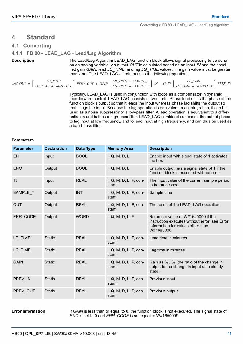
The Lead/Lag Algorithm LEAD_LAG function block allows signal processing to be doneon an analog variable. An output OUT is calculated based on an input IN and the speci-fied gain GAIN, lead LD_TIME, and lag LG_TIME values. The gain value must be greaterthan zero. The LEAD_LAG algorithm uses the following equation:
Typically, LEAD_LAG is used in conjunction with loops as a compensator in dynamicfeed-forward control. LEAD_LAG consists of two parts. Phase lead shifts the phase of thefunction block’s output so that it leads the input whereas phase lag shifts the output sothat it lags the input. Because the lag operation is equivalent to an integration, it can beused as a noise suppressor or a low-pass filter. A lead operation is equivalent to a differ-entiation and is thus a high-pass filter. LEAD_LAG combined can cause the output phaseto lag input at low frequency, and to lead input at high frequency, and can thus be used asa band-pass filter.
Parameters
Parameter Declaration Data Type Memory Area Description
EN Input BOOL I, Q, M, D, L Enable input with signal state of 1 activatesthe box
ENO Output BOOL I, Q, M, D, L Enable output has a signal state of 1 if thefunction block is executed without error
IN Input REAL I, Q, M, D, L, P, con-stant
The input value of the current sample periodto be processed
SAMPLE_T Output INT I, Q, M, D, L, P, con-stant
Sample time
OUT Output REAL I, Q, M, D, L, P, con-stant
The result of the LEAD_LAG operation
ERR_CODE Output WORD I, Q, M, D, L, P Returns a value of W#16#0000 if theinstruction executes without error; see ErrorInformation for values other thanW#16#0000
LD_TIME Static REAL I, Q, M, D, L, P, con-stant
Lead time in minutes
LG_TIME Static REAL I, Q, M, D, L, P, con-stant
Lag time in minutes
GAIN Static REAL I, Q, M, D, L, P, con-stant
Gain as % / % (the ratio of the change inoutput to the change in input as a steadystate).
PREV_IN Static REAL I, Q, M, D, L, P, con-stant
Previous input
PREV_OUT Static REAL I, Q, M, D, L, P, con-stant
Previous output
If GAIN is less than or equal to 0, the function block is not executed. The signal state ofENO is set to 0 and ERR_CODE is set equal to W#16#0009.
Description
Error Information
VIPA SPEED7 Library Standard
Converting > FB 80 - LEAD_LAG - Lead/Lag Algorithm
HB00 | OPL_SP7-LIB | SW90JS0MA V10.003 | en | 18-45 11

4.1.2 FC 93 - SEG - Seven Segment DecoderThe Seven Segment Decoder SEG function converts each of the four hexadecimal digitsin the designated source data word IN into four equivalent 7-segment display codes andwrites it to the output destination double word OUT. The Figure below shows the relation-ship between the input hex digits and the output bit patterns.
Parameters
Digit – g f e d c b a Display
0 0 0 0 0 0 1 1 1 1 1 1 0
0 0 0 1 0 0 0 0 0 1 1 0 1
0 0 1 0 0 1 0 1 1 0 1 1 2
0 0 1 1 0 1 0 0 1 1 1 1 3
0 1 0 0 0 1 1 0 0 1 1 0 4
0 1 0 1 0 1 1 0 1 1 0 1 5
0 1 1 0 0 1 1 1 1 1 0 1 6
0 1 1 1 0 0 0 0 0 1 1 1 7
1 0 0 0 0 1 1 1 1 1 1 1 8
1 0 0 1 0 1 1 0 0 1 1 1 9
1 0 1 0 0 1 1 1 0 1 1 1 A
1 0 1 1 0 1 1 1 1 1 0 0 b
1 1 0 0 0 0 1 1 1 0 0 1 C
1 1 0 1 0 1 0 1 1 1 1 0 d
1 1 1 0 0 1 1 1 1 0 0 1 E
1 1 1 1 0 1 1 1 0 0 0 1 F
Parameters
Parameter Declaration Data Type Memory Area Description
EN Input BOOL I, Q, M, D, L Enable input with signal state of 1 activates thebox
ENO Output BOOL I, Q, M, D, L Enable output has a signal state of 1 if the func-tion is executed without error
IN Input WORD I, M, D, P,
or constant
Source data word in four hexadecimal digits
OUT Output DWORD Q, M, D, L, P Destination bit pattern in four bytes
This function does not detect any error conditions.
Description
Error Information
VIPA SPEED7 LibraryStandard
Converting > FC 93 - SEG - Seven Segment Decoder
HB00 | OPL_SP7-LIB | SW90JS0MA V10.003 | en | 18-45 12

4.1.3 FC 94 - ATH - ASCII to HexThe ASCII to Hex (ATH) function converts the ASCII character string pointed to by IN intopacked hexadecimal digits and stores these in the destination table pointed to by OUT.Since 8 bits are required for the ASCII character and only 4 bits for the hexadecimal digit,the output word length is only half of the input word length. The ASCII characters are con-verted and placed into the hexadecimal output in the same order as they are read in. Ifthere is an odd number of ASCII characters, the hexadecimal digit is padded with zeros inthe right-most nibble of the last converted hexadecimal digit.
Parameter Declaration Data Type Memory Area Description
EN Input BOOL I, Q, M, D, L Enable input with signal state of 1 activatesthe box
ENO Output BOOL I, Q, M, D, L Enable output has a signal state of 1 if thefunction is executed without error
IN Input Pointer* I, Q, M, D, L Points to the starting location of an ASCIIstring
N Input INT I, Q, M, L, P Number of ASCII input characters to be con-verted
RET_VAL Output WORD I, Q, M, D, L, P Returns a value of W#16#0000 if theinstruction executes without error; see ErrorInformation for values other thanW#16#0000
OUT Output Pointer* Q, M, D, L Points to the starting location of the table
*) Double word pointer format for area-crossing register indirect addressing
If any ASCII character is found to be invalid, it is converted as 0. The signal state of ENOis set to 0 and RET_VAL is set equal to W#16#0007.
4.1.4 FC 95 - HTA - Hex to ASCIIThe Hex to ASCII (HTA) function converts packed hexadecimal digits, pointed to by IN,and stores them in the destination string pointed to by OUT. Since 8 bits are required forthe character and only 4 bits for the hex digit, the output word length is two times that ofthe input word length. Each nibble of the hexadecimal digit is converted into a characterin the same order as they are read in (left-most nibble of a hexadecimal digit is convertedfirst, followed by the right-most nibble of that same digit).
Parameters
Parameter Declaration Data Type Memory Area Description
EN Input BOOL I, Q, M, D, L Enable input with signal state of 1 activatesthe box
ENO Output BOOL I, Q, M, D, L Enable output has a signal state of 1 if thefunction is executed without error
IN Input Pointer * I, Q, M, D Points to the starting location of the hexa-decimal digit string
Description
Parameters
Error Information
Description
VIPA SPEED7 Library Standard
Converting > FC 95 - HTA - Hex to ASCII
HB00 | OPL_SP7-LIB | SW90JS0MA V10.003 | en | 18-45 13

Parameter Declaration Data Type Memory Area Description
N Input WORD I, Q, M, L, P Number of hex input bytes to be converted
OUT Output Pointer * Q, M, D, L Points to the starting location of the destina-tion table
*) Double word pointer format for area-crossing register indirect addressing
This function does not detect any error conditions.
4.1.5 FC 96 - ENCO - Encode Binary PositionThe Encode Binary Position ENCO function converts the contents of IN to the 5-bit binarynumber corresponding to the bit position of the right-most set bit in IN and returns theresult as the function’s value. If IN is either 0000 0001 or 0000 0000, a value of 0 isreturned.
Parameters
Parameter Declaration Data Type Memory Area Description
EN Input BOOL I, Q, M, D, L Enable input with signal state of 1 activatesthe box
ENO Output BOOL I, Q, M, D, L Enable output has a signal state of 1 if thefunction is executed without error
IN Input DWORD I, M, D, L, P,
or constant
Value to be encoded
RET_VAL Input INT Q, M, D, L, P Value returned (contains 5-bit binarynumber)
This function does not detect any error conditions.
4.1.6 FC 97 - DECO - Decode Binary PositionThe Decode Binary Position DECO function converts a 5-bit binary number (0 – 31) frominput IN to a value by setting the corresponding bit position in the function’s return value.If IN is greater than 31, a modulo 32 operation is performed to get a 5-bit binary number.
Parameters
Parameter Declaration Data Type Memory Area Description
EN Input BOOL I, Q, M, D, L Enable input with signal state of 1 activatesthe box
ENO Output BOOL I, Q, M, D, L Enable output has a signal state of 1 if thefunction is executed without error
IN Input WORD I, M, D, L, P, constant Variable to decode
RET_VAL Output DWORD Q, M, D, L, P Value returned
Error Information
Description
Error Information
Description
VIPA SPEED7 LibraryStandard
Converting > FC 97 - DECO - Decode Binary Position
HB00 | OPL_SP7-LIB | SW90JS0MA V10.003 | en | 18-45 14

This function does not detect any error conditions.
4.1.7 FC 98 - BCDCPL - Tens ComplementThe Tens Complement BCDCPL function returns the Tens complement of a 7-digit BCDnumber IN. The mathematical formula for this operation is the following:
10000000 (in BCD) - 7digit BCD value = Tens complement value (in BCD)
Parameters
Parameter Declaration Data Type Memory Area Description
EN Input BOOL I, Q, M, D, L Enable input with signal state of 1 activatesthe box
ENO Output BOOL I, Q, M, D, L Enable output has a signal state of 1 if thefunction is executed without error
IN Input DWORD I, M, D, L, P, constant 7-digit BCD number
RET_VAL Output DWORD Q, M, D, L, P Value returned
This function does not detect any error conditions.
4.1.8 FC 99 - BITSUM - Sum Number of BitsThe Sum Number of Bits BITSUM function counts the number of bits that are set to avalue of 1 in the input IN and returns this as the function’s value.
Parameter
Parameter Deklaration Datentyp Speicherbereich Beschreibung
EN Input BOOL I, Q, M, D, L Enable input with signal state of 1 activatesthe box
ENO Output BOOL I, Q, M, D, L Enable output has a signal state of 1 if thefunction is executed without error
IN Input DWORD I, M, D, L, P, constant Variable to count bits in
RET_VAL Output INT Q, M, D, L, P Value returned
This function does not detect any error conditions.
4.1.9 FC 105 - SCALE - Scaling ValuesThe Scaling Values SCALE function takes an integer value IN and converts it to a realvalue in engineering units scaled between a low and a high limit LO_LIM and HI_LIM.The result is written to OUT. The SCALE function uses the equation:
Error Information
Description
Error Information
Description
Error Information
Description
VIPA SPEED7 Library Standard
Converting > FC 105 - SCALE - Scaling Values
HB00 | OPL_SP7-LIB | SW90JS0MA V10.003 | en | 18-45 15

The constants K1 and K2 are set based upon whether the input value is BIPOLAR orUNIPOLAR.
n BIPOLAR:– The input integer value is assumed to be between -27648 and 27648, therefore,
K1 = -27648,0 and K2 = +27648,0.n UNIPOLAR:
– The input integer value is assumed to be between 0 and 27648, therefore,K1 = 0,0 and K2 = +27648,0.
If the input integer value is greater than K2, the output OUT is clamped to HI_LIM, and anerror is returned. If the input integer value is less than K1, the output OUT is clamped toLO_LIM, and an error is returned. Reverse scaling can be obtained by programmingLO_LIM > HI_LIM. With reverse scaling, the value of the output decreases as the value ofthe input increases.
Parameters
Parameter Declaration Data Type Memory Area Description
EN INPUT BOOL I, Q, M, D, L n Enable– TRUE: activates the function– FALSE: deactivates the function
ENO OUTPUT BOOL I, Q, M, D, L n Status– TRUE: function executed without
error
IN INPUT INT I, Q, M, D, L, con-stant
The input value to be scaled to a REALvalue in engineering units
HI_LIM INPUT REAL I, Q, M, D, L, P, con-stant
Upper limit in engineering units
LO_LIM INPUT REAL I, Q, M, D, L, P, con-stant
Lower limit in engineering units
BIPOLAR INPUT BOOL I, Q, M, D, L A signal state of 1 indicates the input valueis bipolar, a signal state of "0" indicates uni-polar
OUT OUTPUT REAL I, Q, M, D, L, P The result of the scale conversion
RET_VAL INPUT WORD I, Q, M, D, L, P Returns a value of W#16#0000 if theinstruction executes without error; see ErrorInformation for values other thanW#16#0000
n If the input integer value is greater than K2, the output OUT is clamped to HI_LIM,and an error is returned.
n If the input integer value is less than K1, the output OUT is clamped to LO_LIM, andan error is returned.
n The signal state of ENO is set to FALSE and RET_VAL is set equal to W#16#0008.
4.1.10 FC 106 - UNSCALE - Unscaling ValuesThe Unscaling Values UNSCALE function takes a real input value IN in engineering unitsscaled between a low and a high limit LO_LIM and HI_LIM and converts it to an integervalue. The result is written to OUT. The UNSCALE function uses the equation:
Error information
Description
VIPA SPEED7 LibraryStandard
Converting > FC 106 - UNSCALE - Unscaling Values
HB00 | OPL_SP7-LIB | SW90JS0MA V10.003 | en | 18-45 16

and sets the constants K1 and K2 based upon whether the input value is BIPOLAR orUNIPOLAR.
n BIPOLAR:– The input integer value is assumed to be between -27648 and 27648, therefore,
K1 = -27648.0 and K2 = +27648.0.n UNIPOLAR:
– The input integer value is assumed to be between 0 and 27648, therefore,K1 = 0.0 and K2 = +27648.0.
If the input value is outside the LO_LIM and HI_LIM range, the output OUT is clamped tothe nearer of either the low limit or the high limit of the specified range for its type(BIPOLAR or UNIPOLAR), and an error is returned.
Parameters
Parameter Declaration Data Type Memory Area Description
EN Input BOOL I, Q, M, D, L n Enable– TRUE: activates the function– FALSE: deactivates the function
ENO Output BOOL I, Q, M, D, L n Status– TRUE: function executed without
error
IN Input REAL I, Q, M, D, L, P, con-stant
The input value to be unscaled to an integervalue
HI_LIM Input REAL I, Q, M, D, L, P, con-stant
Upper limit in engineering units
LO_LIM Input REAL I, Q, M, D, L, P, con-stant
Lower limit in engineering units
BIPOLAR Input BOOL I, Q, M, D, L A signal state of 1 indicates the input valueis bipolar and a signal state of "0" indicatesunipolar
OUT Output INT I, Q, M, D, L, P The result of the scale conversion
RET_VAL Output WORD I, Q, M, D, L, P Returns a value of W#16#0000 if theinstruction executes without error; see ErrorInformation for values other thanW#16#0000
If the input real value is outside the LO_LIM and HI_LIM range the output OUT isclamped to the nearer of either the low limit or the high limit of the specified range for itstype (BIPOLAR or UNIPOLAR), and an error is returned. The signal state of ENO is set to0 and RET_VAL is set equal to W#16#0008.
4.1.11 FC 108 - RLG_AA1 - Issue an Analog ValueThe function RLG_AA1 (Issue an Analog Value) transforms an Input Value XE (FixedPoint Number) into an output value for an analog output module in accordance with thenominal range between OGR and UGR. If the nominal range is exceeded, an error mes-sage is displayed.
Error Information
Description
VIPA SPEED7 Library Standard
Converting > FC 108 - RLG_AA1 - Issue an Analog Value
HB00 | OPL_SP7-LIB | SW90JS0MA V10.003 | en | 18-45 17

Parameter Datentyp Speicherbereich Beschreibung
XE INT I, Q, M, L, D, constant Input value XE as a fixed point number
BG INT I, Q, M, L, D, constant Specify the module address
KNKT WORD I, Q, M, L, D, constant Channel number KN
Channel type KT
OGR INT I, Q, M, L, D, constant Upper limit of the input value XE
UGR INT I, Q, M, L, D, constant Lower limit of the input value XE
FEH BOOL I, Q, M, L, D Error bit
BU BOOL I, Q, M, L, D Range excess
n The BG parameter– There is no address check. The range is the whole P area.
This function is only used to convert the FB251 of an existing S5 programof an S5 CPU 941 to 944 to a function of an S7 program for the S7-400programmable controller.
4.1.12 FC 109 - RLG_AA2 - Write Analog Value 2The function RLG_AA2 (Issue an Analog Value) transforms an Input Value XE (FloatingPoint Number) into an output value for an analog output module in accordance with thenominal range between OGR and UGR. If the nominal range is exceeded, an error mes-sage is displayed.
Parameter Data Type Memory Area Description
XE REAL I, Q, M, L, D, constant Input value XE as a floating point number
BG INT I, Q, M, L, D, constant Specify the module address
P_Q WORD I, Q, M, L, D, constant Peripheriebereich normal/erweitert
KNKT WORD I, Q, M, L, D, constant Channel number KN
Channel type KT
OGR REAL I, Q, M, L, D, constant Upper limit of the input value XE
UGR REAL I, Q, M, L, D, constant
const.
Lower limit of the input value XE
FEH BOOL I, Q, M, L, D Error bit
BU BOOL I, Q, M, L, D Range excess
Differences between S5and S7
Description
VIPA SPEED7 LibraryStandard
Converting > FC 109 - RLG_AA2 - Write Analog Value 2
HB00 | OPL_SP7-LIB | SW90JS0MA V10.003 | en | 18-45 18

n The BG parameter– There is no address check. The range is the whole P area.
n In S7, no value is assigned to the parameter P_Q.n A process image of the S5 I/O areas P/Q/IM3/IM4 is made in the S7 I/O area. You
must assign the I/O area in the configuration table.
This function is only used to convert the FB41 of an existing S5 programof an S5 CPU 928B, 945 or 948 to a function of an S7 program for theS7-400 programmable controller.
4.1.13 FC 110 - PER_ET1 - Read/Write Ext. Per. 1The function PER_ET1 (Reading and Writing for Expanded Peripheries) transfers either aperipheral area into a CPU-internal area or vice-versa (depending on the parameterassignment). In this way, input bytes can be read from, and output bytes written to, theexpanded I/O. If a data block is selected as an internal area, the block must have beenset up by the user with the necessary length prior to calling up the function.
Parameter Data Type Memory Area Description
PBIB WORD I, Q, M, L, D, constant Specify the areas to be processed
ANF INT I, Q, M, L, D, constant Beginning of the internal area
ANEN WORD I, Q, M, L, D, constant Beginning and end of the block on the interfacemodule
E_A BOOL I, Q, M, L, D, constant Transfer direction
PAFE BOOL I, Q, M, L, D Parameter assignment error
n The PBIB parameter– In S7, the I/O area is assigned values as follows:
S5 S7
P area 0 to 255 P area 0 to 255
Q area 0 to 255 P area 256 to 511
IM3 area 0 to 255 P area 512 to 767
IM4 area 0 to 255 P area 768 to 1023
DB 0 to 255 DB 0 to 255
DX 0 to 255 DB 256 to 511
M 0 to 199 M 0 to 199
S Error message: "Invalid range"
n A process image of the S5 I/O areas P/Q/IM3/IM4 is made in the S7 I/O area. Youmust assign the I/O area in the configuration table.
Differences between S5and S7
Description
Differences between S5and S7
VIPA SPEED7 Library Standard
Converting > FC 110 - PER_ET1 - Read/Write Ext. Per. 1
HB00 | OPL_SP7-LIB | SW90JS0MA V10.003 | en | 18-45 19

This function is only used to convert the FB196 of an existing S5 programof an S5 CPU 95U, 103, 941 to 944, 945, 928B, 948 to a function of anS7 program for the S7-300/400 programmable controller.
4.1.14 FC 111 - PER_ET2 - Read/Write Ext. Per. 2The function PER_ET2 (Reading and Writing for Expanded Peripheries) transfers either aperipheral area into a CPU-internal area or vice-versa (depending on the parameterassignment). In this way, input bytes can be read from, and output bytes written to, theexpanded I/O. If a data block is selected as an internal area, the block must have beenset up by the user with the necessary length prior to calling up the function.
n The PBIB parameter (defined in DB)– In S7, the I/O area is assigned values as follows:
S5 S7
P area 0 to 255 P area 0 to 255
Q area 0 to 255 P area 256 to 511
IM3 area 0 to 255 P area 512 to 767
IM4 area 0 to 255 P area 768 to 1023
DB 0 to 255 DB 0 to 255
DX 0 to 255 DB 256 to 511
M 0 to 199 M 0 to 199
S Error message: "Invalid range"
n A process image of the S5 I/O areas P/Q/IM3/IM4 is made in the S7 I/O area. Youmust assign the I/O area in the configuration table.
This function is only used to convert the FB197 of an existing S5 programof an S5 CPU 95U, 103, 941 to 944, 945, 928B, 948 to a function of anS7 program for the S7-300/400 programmable controller.
Description
Differences between S5and S7:
VIPA SPEED7 LibraryStandard
Converting > FC 111 - PER_ET2 - Read/Write Ext. Per. 2
HB00 | OPL_SP7-LIB | SW90JS0MA V10.003 | en | 18-45 20

4.2 IEC4.2.1 Date and time as complex data types
The DATE_AND_TIME data type is a complex data type like ARRAY, STRING, andSTRUCT. The permissible memory areas for complex data types are the data block (DB)and local data (L stack) areas. If you use the data type DATE_AND_TIME as formalparameter in an instruction, due to the complex data type you can specify only one of thefollowing formats:
n A block-specific symbol from the variable declaration table for a specific blockn A symbolic name for a data block, such as e.g. "DB_sys_info.System_Time", made
up of the following parts:– A name defined in the symbol table for the number of the data block (e.g.
"DB_sys_info" for DB 5)– A name defined within the data block for the DATE_AND_TIME element (e.g.
"Time" for a variable of data type DATE_AND_TIME contained in DB 5)
You cannot pass constants as actual parameters to formal parameters ofthe complex data types, including DATE_AND_TIME. Also, you cannotpass absolute addresses as actual parameters to DATE_AND_TIME.
4.2.2 FC 1 - AD_DT_TM - Add duration to instant of timeThe function FC 1 adds a duration D (time) to an instant of time T (date and time) andprovides a new instant of time (date and time) as the result. The instant of time T must bein the range DT#1990-01-01-00:00:00.000 ... DT#2089-12-31-23:59:59.999. The functiondoes not check the input parameters. If the result of the addition is not within the validrange, the result is limited to the corresponding value and the binary result (BR) bit of thestatus word is set to "0".
Parameter Declaration Data type Memory area Description
T* INPUT DATE_AND_TIME D, L Instant of time in format DT
D INPUT TIME I, Q, M, D, L
Constant
Duration in Format TIME
RET_VAL* OUTPUT DATE_AND_TIME D, L Sum in format DT*) You can assign only a symbolically defined variable for the parameter.
4.2.3 FC 2 - CONCAT - Concatenate two STRING variablesThe function FC 2 concatenates two STRING variables together to form one string. If theresulting string is longer than the variable given at the output parameter, the result stringis limited to the maximum set length and the BR bit is set to "0".
Actual parameters forDATE_AND_TIME
Description
Parameter
Description
VIPA SPEED7 Library Standard
IEC > FC 2 - CONCAT - Concatenate two STRING variables
HB00 | OPL_SP7-LIB | SW90JS0MA V10.003 | en | 18-45 21

Parameter
Parameter Declaration Data type Memory area Description
IN1* INPUT STRING D, L Input variable in format STRING
IN2* INPUT STRING D, L Input variable in format STRING
RET_VAL* OUTPUT STRING D, L Concatenated string*) You can assign only a symbolically defined variable for the parameter.
4.2.4 FC 3 - D_TOD_DT - Combine DATE and TIME_OF_DAYThe function FC 3 combines the data formats DATE and TIME_OF_DAY (TOD) and con-verts these formats to the data format DATE_AND_TIME (DT). The input value IN1 mustbe in the range DATE#1990-01-01 ... DATE#2089-12-31. The function does not check theinput parameters and does not report any errors.
Parameter
Parameter Declaration Data type Memory area Description
IN1 INPUT DATE I, Q, M, D, L
Constant
Input variable in format DATE
IN2 INPUT TIME_OF_DAY I, Q, M, D, L
Constant
Input variable in format TOD
RET_VAL* OUTPUT DATE_AND_TIME D, L Return value in format DT*) You can assign only a symbolically defined variable for the parameter.
4.2.5 FC 4 - DELETE - Delete in a STRING variableThe function FC 4 deletes a number of characters L from the character at position P(inclusive) in a string. The function does not report any errors.
n If L and/or P are equal to zero or if P is greater than the current length of the inputstring, the input string is returned.
n If the sum of L and P is greater than the input string, the string is deleted up to theend.
n If L and/or P is negative, a blank string is returned and the BR bit is set to "0".
Parameter Declaration Data type Memory area Description
IN* INPUT STRING D, L STRING variable to be deleted in
L INPUT INT I, Q, M, D, L
Constant
Number of characters to bedeleted
P INPUT INT I, Q, M, D, L
Constant
Position of 1. character to bedeleted
Description
Description
Parameter
VIPA SPEED7 LibraryStandard
IEC > FC 4 - DELETE - Delete in a STRING variable
HB00 | OPL_SP7-LIB | SW90JS0MA V10.003 | en | 18-45 22

Parameter Declaration Data type Memory area Description
RET_VAL* OUTPUT STRING D, L Result string*) You can assign only a symbolically defined variable for the parameter.
4.2.6 FC 5 - DI_STRNG - Convert DINT to STRINGThe function FC 5 converts a variable in DINT data format to a string. The string is shownpreceded by a sign. If the variable given at the return parameter is too short, no conver-sion takes place and the BR bit is set to "0".
Parameter Declaration Data type Memory area Description
I INPUT DINT I, Q, M, D, L
Constant
Input value
RET_VAL* OUTPUT STRING D, L Result string*) You can assign only a symbolically defined variable for the parameter.
4.2.7 FC 6 - DT_DATE - Extract DATE from DTThe function FC 6 extracts the data format DATE from the format DATE_AND_TIME.DATE value is between the limits DATE#1990-1-1 and DATE#2089-12-31. The functiondoes not report any errors.
Parameter Declaration Data type Memory area Description
IN* INPUT DATE_AND_TIME D, L Input variable in format DT
RET_VAL OUTPUT DATE I, Q, M, D, L Return value in format DATE*) You can assign only a symbolically defined variable for the parameter.
4.2.8 FC 7 - DT_DAY - Extract day of the week from DTThe function FC 7 extracts the day of the week from the format DATE_AND_TIME. Thefunction does not report any errors. The day of the week is returned as INTEGER value.
n 1: Sundayn 2: Mondayn 3: Tuesdayn 4: Wednesdayn 5: Thursdayn 6: Fridayn 7: Saturday
Description
Parameter
Description
Parameter
Description
Parameter
VIPA SPEED7 Library Standard
IEC > FC 7 - DT_DAY - Extract day of the week from DT
HB00 | OPL_SP7-LIB | SW90JS0MA V10.003 | en | 18-45 23

Parameter Declaration Data type Memory area Description
IN* INPUT DATE_AND_TIME D, L Input variable in format DT
RET_VAL OUTPUT INT I, Q, M, D, L Return value in format INT*) You can assign only a symbolically defined variable for the parameter.
4.2.9 FC 8 - DT_TOD - Extract TIME_OF_DAY from DTThe function FC 8 extracts the data format TIME_OF_DAY from the formatDATE_AND_TIME. The function does not report any errors.
Parameter Declaration Data type Memory area Description
IN* INPUT DATE_AND_TIME D, L Input variable in format DT
RET_VAL OUTPUT TIME_OF_DAY I, Q, M, D, L Return value in format TOD*) You can assign only a symbolically defined variable for the parameter.
4.2.10 FC 9 - EQ_DT - Compare DT for equalityThe function FC 9 compares the contents of two variables in the data type formatDATE_AND_TIME to determine if they are equal and outputs the result of the comparisonas a return value. The return value has the signal state "1" if the time at parameter DT1 isthe same as the time at parameter DT2. The function does not report any errors.
Parameter Declaration Data type Memory area Description
DT1* INPUT DATE_AND_TIME D, L Input variable in format TD
DT2* INPUT DATE_AND_TIME D, L Input variable in format TD
RET_VAL OUTPUT BOOL I, Q, M, D, L Comparison result*) You can assign only a symbolically defined variable for the parameter.
4.2.11 FC 10 - EQ_STRNG - Compare STRING for equalThe function FC 10 compares the contents of two variables in the format STRING todetermine if they are equal and outputs the result of the comparison as a return value.The return value has the signal state "1" if the string at parameter S1 is the same as thestring at parameter S2. The function does not report any errors.
Parameter Declaration Data type Memory area Description
S1* INPUT STRING D, L Input variable in format STRING
S2* INPUT STRING D, L Input variable in format STRING
Description
Parameter
Description
Parameter
Description
Parameter
VIPA SPEED7 LibraryStandard
IEC > FC 10 - EQ_STRNG - Compare STRING for equal
HB00 | OPL_SP7-LIB | SW90JS0MA V10.003 | en | 18-45 24

Parameter Declaration Data type Memory area Description
RET_VAL OUTPUT BOOL I, Q, M, D, L Comparison result*) You can assign only a symbolically defined variable for the parameter.
4.2.12 FC 11 - FIND - Find in a STRING variableThe function FC 11 provides the position of the second string IN2 within the first stringIN1. The search starts on the left; the first occurrence of the string is reported. If thesecond string is not found in the first, zero is returned. The function does not report anyerrors.
Parameter Declaration Data type Memory area Description
IN1* INPUT STRING D, L STRING variable to be searchedin
IN2* INPUT STRING D, L STRING variable to be found
RET_VAL OUTPUT INT I, Q, M, D, L Position of the string found*) You can assign only a symbolically defined variable for the parameter.
4.2.13 FC 12 - GE_DT - Compare DT for greater than or equalThe function FC 12 compares the contents of two variables in the data formatDATE_AND_TIME to determine if one is greater or equal to the other and outputs theresult of the comparison as a return value. The return value has the signal state "1" if thetime at parameter DT1 is greater (younger) than the time at parameter DT2 or if bothinstants of time are the same. The function does not report any errors.
Parameter Declaration Data type Memory area Description
DT1* INPUT DATE_AND_TIME D, L Input variable in format TD
DT2* INPUT DATE_AND_TIME D, L Input variable in format TD
RET_VAL OUTPUT BOOL I, Q, M, D, L Comparison result*) You can assign only a symbolically defined variable for the parameters.
4.2.14 FC 13 - GE_STRNG - Compare STRING for greater than or equalThe function FC 13 compares the contents of two variables in the data format STRING todetermine if one is greater or equal to the other and outputs the result of the comparisonas a return value. The return value has the signal state "1" if the string at parameter S1 isgreater than or equal to the string at parameter S2. The characters are compared by theirASCII code (e.g. 'a' is greater than 'A'), starting from the left. The first character to be dif-ferent decides the result of the comparison. If the left part of the longer string is identicalto the shorter string, the longer string is considered as greater. The function does notreport any errors.
Description
Parameter
Description
Parameter
Description
VIPA SPEED7 Library Standard
IEC > FC 13 - GE_STRNG - Compare STRING for greater than or equal
HB00 | OPL_SP7-LIB | SW90JS0MA V10.003 | en | 18-45 25

Parameter Declaration Data type Memory area Description
S1* INPUT STRING D, L Input variable in format STRING
S2* INPUT STRING D, L Input variable in format STRING
RET_VAL OUTPUT BOOL I, Q, M, D, L Comparison result*) You can assign only a symbolically defined variable for the parameter.
4.2.15 FC 14 - GT_DT - Compare DT for greater thanThe function FC 14 compares the contents of two variables in the data formatDATE_AND_TIME to determine if one is greater to the other and outputs the result of thecomparison as a return value. The return value has the signal state "1" if the time atparameter DT1 is greater (younger) than the time at parameter DT2. The function doesnot report any errors.
Parameter Declaration Data type Memory area Description
DT1* INPUT DATE_AND_TIME D, L Input variable in format TD
DT2* INPUT DATE_AND_TIME D, L Input variable in format TD
RET_VAL OUTPUT BOOL I, Q, M, D, L Comparison result*) You can assign only a symbolically defined variable for the parameter.
4.2.16 FC 15 - GT_STRNG - Compare STRING for greater thanThe function FC 15 compares the contents of two variables in the data format STRING tofind out if the first is greater than the other and outputs the result of the comparison as areturn value. The return value has the signal state "1" if the string at parameter S1 isgreater than the string at parameter S2. The characters are compared by their ASCIIcode (e.g. 'a' is greater than 'A'), starting from the left. The first character to be differentdecides the result of the comparison. If the left part of the longer string is identical to theshorter string, the longer string is considered as greater. The function does not report anyerrors.
Parameter Declaration Data type Memory area Description
S1* INPUT STRING D, L Input variable in format STRING
S2* INPUT STRING D, L Input variable in format STRING
RET_VAL OUTPUT BOOL I, Q, M, D, L Comparison result*) You can assign only a symbolically defined variable for the parameter.
Parameter
Description
Parameter
Description
Parameter
VIPA SPEED7 LibraryStandard
IEC > FC 15 - GT_STRNG - Compare STRING for greater than
HB00 | OPL_SP7-LIB | SW90JS0MA V10.003 | en | 18-45 26

4.2.17 FC 16 - I_STRNG - Convert INT to STRINGThe function FC 16 converts a variable in DINT data format to a string. The string isshown preceded by a sign. If the variable given at the return parameter is too short, noconversion takes place and the BR bit is set to "0".
Parameter
Parameter Declaration Data type Memory area Description
I INPUT INT I, Q, M, D, L
Constant
Input value
RET_VAL* OUTPUT STRING D, L Result string*) You can assign only a symbolically defined variable for the parameter.
4.2.18 FC 17 - INSERT - Insert in a STRING variableThe function FC 17 inserts a string at parameter IN2 into the string at parameter IN1 afterthe character at position P.
n If P equals zero, the second string is inserted before the first string.n If P is greater than the current length of the first string, the second string is appended
to the first.n If P is negative, a blank string is output and the BR bit is set to "0". The binary result
bit is also set to "0" if the resulting string is longer than the variable given at the outputparameter; in this case the result string is limited to the maximum set length.
Parameter Declaration Data type Memory area Description
IN1* INPUT STRING D, L STRING variable to be insertedinto
IN2* INPUT STRING D, L STRING variable to be inserted
P INPUT INT I, Q, M, D, L
Constant
Insert position
RET_VAL* OUTPUT STRING D, L Result string*) You can assign only a symbolically defined variable for the parameter.
4.2.19 FC 18 - LE_DT - Compare DT for smaller than or equalThe function FC 18 compares the contents of two variables in the formatDATE_AND_TIME to determine if one is smaller or equal to the other and outputs theresult of the comparison as a return value. The return value has the signal state "1" if thetime at parameter DT1 is smaller (older) than the time at parameter DT2 or if bothinstants of time are the same. The function does not report any errors.
Description
Description
Parameter
Description
Parameter
VIPA SPEED7 Library Standard
IEC > FC 18 - LE_DT - Compare DT for smaller than or equal
HB00 | OPL_SP7-LIB | SW90JS0MA V10.003 | en | 18-45 27

Parameter Declaration Data type Memory area Description
DT1* INPUT DATE_AND_TIME D, L Input variable in format TD
DT2* INPUT DATE_AND_TIME D, L Input variable in format TD
RET_VAL* OUTPUT BOOL I, Q, M, D, L Comparison result*) You can assign only a symbolically defined variable for the parameter.
4.2.20 FC 19 - LE_STRNG - Compare STRING for smaller then or equalThe function FC 19 compares the contents of two variables in the format STRING todetermine if one is smaller or equal to the other and outputs the result of the comparisonas a return value. The return value has the signal state "1" if the string at parameter S1 issmaller than or equal to the string at parameter S2. The characters are compared by theirASCII code (e.g. 'A' smaller than 'a'), starting from the left. The first character to be dif-ferent decides the result of the comparison. If the left part of the longer character stringand the shorter character string are the same, the shorter string is smaller. The functiondoes not report any errors.
Parameter Declaration Data type Memory area Description
S1* INPUT STRING D, L Input variable in format STRING
S2* INPUT STRING D, L Input variable in format STRING
RET_VAL OUTPUT BOOL I, Q, M, D, L Comparison result*) You can assign only a symbolically defined variable for the parameter.
4.2.21 FC 20 - LEFT - Left part of a STRING variableThe function FC 20 provides the first L characters of a string.
n If L is greater than the current length of the STRING variable, the input value isreturned.
n With L = 0 and with a blank string as the input value, a blank string is returned.n If L is negative, a blank string is returned and the BR bit of the status word is set to
"0".
Parameter Declaration Data type Memory area Description
IN* INPUT STRING D, L Input variable in format STRING
L INPUT INT I, Q, M, D, L
Constant
Length of the left character string
RET_VAL* OUTPUT STRING D, L Output variable in format STRING*) You can assign only a symbolically defined variable for the parameter.
Description
Parameter
Description
Parameter
VIPA SPEED7 LibraryStandard
IEC > FC 20 - LEFT - Left part of a STRING variable
HB00 | OPL_SP7-LIB | SW90JS0MA V10.003 | en | 18-45 28

4.2.22 FC 21 - LEN - Length of a STRING variableA STRING variable contains two lengths:
n Maximum length– It is given in square brackets when the variables are being defined.
n Current length– This is the number of currently valid characters.
The current length is smaller or equal to the maximum length. The number of bytes occu-pied by a string is 2 greater than the maximum length. The function FC 21 outputs thecurrent length of a string (number of valid characters) as a return value. A blank string (' ')has the length zero. The maximum length is 254. The function does not report any errors.
Parameter Declaration Data type Memory area Description
S* INPUT STRING D, L Input variable in format STRING
RET_VAL OUTPUT INT I, Q, M, D, L Number of current characters*) You can assign only a symbolically defined variable for the parameter.
4.2.23 FC 22 - LIMITThe function FC 22 limits the number value of a variable to limit values which can haveparameters assigned.
n Variables of the data types INT, DINT, and REAL are permitted as input values.n All variables with parameters assigned must be of the same data type.n The variable type is recognized by the ANY pointer.n MN may not be greater as MX.n The output value remains unchanged and the BR bit is set to "0" if:
– a variable with parameters assigned has an invalid data type.– all variables with parameters assigned do not have the same data type.– the lower limit value is greater than the upper limit value.– a REAL variable does not represent a valid floating-point number.
Parameter Declaration Data type Memory area Description
MN INPUT ANY I, Q, M, D, L Lower limit
IN INPUT ANY I, Q, M, D, L Input variable
MX INPUT ANY I, Q, M, D, L Upper limit
RET_VAL OUTPUT ANY I, Q, M, D, L Limited output variable
4.2.24 FC 23 - LT_DT - Compare DT for smaller thanThe function FC 23 compares the contents of two variables in the formatDATE_AND_TIME to determine if one is smaller to the other and outputs the result of thecomparison as a return value. The return value has the signal state "1" if the time atparameter DT1 is smaller (older) than the time at parameter DT2. The function does notreport any errors.
Description
Parameter
Description
Parameter
Description
VIPA SPEED7 Library Standard
IEC > FC 23 - LT_DT - Compare DT for smaller than
HB00 | OPL_SP7-LIB | SW90JS0MA V10.003 | en | 18-45 29

Parameter
Parameter Declaration Data type Memory area Description
DT1* INPUT DATE_AND_TIME D, L Input variable in format TD
DT2* INPUT DATE_AND_TIME D, L Input variable in format TD
RET_VAL OUTPUT BOOL I, Q, M, D, L Comparison result*) You can assign only a symbolically defined variable for the parameter.
4.2.25 FC 24 - LT_STRNG - Compare STRING for smallerThe function FC 24 compares the contents of two variables in the format STRING todetermine if one is smaller to the other and outputs the result of the comparison as areturn value. The return value has the signal state "1" if the string at parameter S1 issmaller than the string at parameter S2. The characters are compared by their ASCIIcode (e.g. 'A' smaller than 'a'), starting from the left. The first character to be differentdecides the result of the comparison. If the left part of the longer character string and theshorter character string are the same, the shorter string is smaller. The function does notreport any errors.
Parameter Declaration Data type Memory area Description
S1* INPUT STRING D, L Input variable in format STRING
S2* INPUT STRING D, L Input variable in format STRING
RET_VAL OUTPUT BOOL I, Q, M, D, L Comparison result*) You can assign only a symbolically defined variable for the parameter.
4.2.26 FC 25 - MAX - Select maximumThe function FC 25 selects the largest of three numerical variable values.
n Variables of the data types INT, DINT, and REAL are permitted as input values.n All variables with parameters assigned must be of the same data type.n The variable type is recognized by the ANY pointer.n The output value remains unchanged and the BR bit is set to "0" if:
– a variable with parameters assigned has an invalid data type.– all variables with parameters assigned do not have the same data type.– a REAL variable does not represent a valid floating-point number.
Parameter Declaration Data type Memory area Description
IN1 INPUT ANY I, Q, M, D, L 1. Input value
IN2 INPUT ANY I, Q, M, D, L 2. Input value
IN3 INPUT ANY I, Q, M, D, L 3. Input value
RET_VAL OUTPUT ANY I, Q, M, D, L Largest of the input values
Description
Parameter
Description
Parameter
VIPA SPEED7 LibraryStandard
IEC > FC 25 - MAX - Select maximum
HB00 | OPL_SP7-LIB | SW90JS0MA V10.003 | en | 18-45 30

The admitted data types INT, DINT and REAL must be entered in theANY pointer. Such parameters as "MD20" are also admitted, but youmust define the corresponding data type of "MD20" in "Symbol".
CALL FC 25IN1 := P#M 10.0 DINT 1IN2 := MD20IN3 := P#DB1.DBX 0.0 DINT 1RET_VAL := P#M 40.0 DINT 1= M 0.0
4.2.27 FC 26 - MID - Middle part of a STRING variableThe function FC 26 provides the middle part of a string (L characters from the character Pinclusive).
n If the sum of L and (P-1) exceeds the current length of the STRING variables, a stringis returned from the character P to the end of the input value.
n In all other cases (P is outside the current length, P and/or L are equal to zero or neg-ative), a blank string is returned and the BR bit is set to "0".
Parameter Declaration Data type Memory area Description
IN* INPUT STRING D, L Input variable in format STRING
L INPUT INT I, Q, M, D, L
Constant
Length of the middle characterstring
P INPUT INT I, Q, M, D, L
Constant
Position of first character
RET_VAL* OUTPUT STRING D, L Output variable in format STRING*) You can assign only a symbolically defined variable for the parameter.
4.2.28 FC 27 - MIN - Select minimumThe function FC 27 selects the smallest of three numerical variable values.
n Variables of the data types INT, DINT, and REAL are permitted as input values.n All variables with parameters assigned must be of the same data type.n The variable type is recognized by the ANY pointer.n The output value remains unchanged and the BR bit is set to "0" if:
– a variable with parameters assigned has an invalid data type.– all variables with parameters assigned do not have the same data type.– a REAL variable does not represent a valid floating-point number.
Example in STL:
Description
Parameter
Description
Parameter
VIPA SPEED7 Library Standard
IEC > FC 27 - MIN - Select minimum
HB00 | OPL_SP7-LIB | SW90JS0MA V10.003 | en | 18-45 31

Parameter Declaration Data type Memory area Description
IN1 INPUT ANY I, Q, M, D, L 1. Input value
IN2 INPUT ANY I, Q, M, D, L 2. Input value
IN3 INPUT ANY I, Q, M, D, L 3. Input value
RET_VAL OUTPUT ANY I, Q, M, D, L Smallest of the input values
The admitted data types INT, DINT and REAL must be entered in theANY pointer. Such parameters as "MD20" are also admitted, but youmust define the corresponding data type of "MD20" in "Symbol".
CALL FC 27IN1 := P#M 10.0 DINT 1IN2 := MD20IN3 := P#DB1.DBX 0.0 DINT 1RET_VAL := P#M 40.0 DINT 1= M 0.0
4.2.29 FC 28 - NE_DT - Compare DT for unequalThe function FC 28 compares the contents of two variables in the formatDATE_AND_TIME to determine if they are unequal and outputs the result of the compar-ison as a return value. The return value has the signal state "1" if the time at parameterDT1 is unequal the time at parameter DT2. The function does not report any errors.
Parameter Declaration Data type Memory area Description
DT1* INPUT DATE_AND_TIME D, L Input variable in format TD
DT2* INPUT DATE_AND_TIME D, L Input variable in format TD
RET_VAL OUTPUT BOOL I, Q, M, D, L Comparison result*) You can assign only a symbolically defined variable for the parameter.
4.2.30 FC 29 - NE_STRNG - Compare STRING for unequalThe function FC 29 compares the contents of two variables in the format STRING todetermine if they are unequal and outputs the result of the comparison as a return value.The return value has the signal state "1" if the string at parameter S1 is unequal to thestring at parameter S2. The function does not report any errors.
Example in STL:
Description
Parameter
Description
VIPA SPEED7 LibraryStandard
IEC > FC 29 - NE_STRNG - Compare STRING for unequal
HB00 | OPL_SP7-LIB | SW90JS0MA V10.003 | en | 18-45 32

Parameter
Parameter Declaration Data type Memory area Description
S1* INPUT STRING D, L Input variable in format STRING
S2* INPUT STRING D, L Input variable in format STRING
RET_VAL OUTPUT BOOL I, Q, M, D, L Comparison result*) You can assign only a symbolically defined variable for the parameter.
4.2.31 FC 30 - R_STRNG - Convert REAL to STRINGThe function FC 30 converts a variable in REAL data format to a string.
n The string is shown with 14 digits:±v.nnnnnnnE±xx– ±: Sign– v: 1 digit before the decimal point– n: 7 digits after the decimal point– x: 2 exponential digits
n If the variable given at the return parameter is too short or if no valid floating-pointnumber is given at parameter IN, no conversion takes place and the BR bit is set to"0".
Parameter Declaration Data type Memory area Description
IN INPUT REAL I, Q, M, D, L
Constant
Input value
RET_VAL* OUTPUT STRING D, L Result string*) You can assign only a symbolically defined variable for the parameter.
4.2.32 FC 31 - REPLACE - Replace in a STRING variableThe function FC 31 replaces a number of characters L of the first string IN1 starting at thecharacter at position P (inclusive) with the entire second string IN2.
n If L is equal to zero and P is not equal to zero, the first string is returned.n If L is equal to zero and P is equal to zero, the second string is precent to the first
string.n If L is not equal to zero and P is equal to zero or one, the string is replaced from the
1. character (inclusive).n If P is outside the first string, the second string is appended to the first string.n If L and/or P is negative, a blank string is returned and the BR bit is set to "0". The BR
bit is also set to "0" if the resulting string is longer than the variable given at the outputparameter; in this case the result string is limited to the maximum set length.
Description
Parameter
Description
VIPA SPEED7 Library Standard
IEC > FC 31 - REPLACE - Replace in a STRING variable
HB00 | OPL_SP7-LIB | SW90JS0MA V10.003 | en | 18-45 33

Parameter
Parameter Declaration Data type Memory area Description
IN1* INPUT STRING D, L STRING variable to be inserted into
IN2* INPUT STRING D, L STRING variable to be inserted
L INPUT INT I, Q, M, D, L
Constant
Number of characters to be replaced
P INPUT INT I, Q, M, D, L
Constant
Position of 1. character to bereplaced
RET_VAL* OUTPUT STRING D, L Result string*) You can assign only a symbolically defined variable for the parameter.
4.2.33 FC 32 - RIGHT - Right part of a STRING variableThe function FC 32 provides the last L characters of a string.
n If L is greater than the current length of the STRING variable, the input value isreturned.
n With L = 0 and with a blank string as the input value, a blank string is returned.n If L is negative, a blank string is returned and the BR bit is set to "0".
Parameter Declaration Data type Memory area Description
IN* INPUT STRING D, L Input variable in format STRING
L INPUT INT I, Q, M, D, L
Constant
Length of the right character string
RET_VAL* OUTPUT STRING D, L Output variable in format STRING*) You can assign only a symbolically defined variable for the parameter.
4.2.34 FC 33 - S5TI_TIM - Convert S5TIME to TIMEThe function FC 33 converts the data format S5TIME to the data format TIME. If theresult of the conversion is outside the TIME range, the result is limited to the corre-sponding value and the binary result (BR) bit is set to "0".
Parameter Declaration Data type Memory area Description
IN INPUT S5TIME I, Q, M, D, L
Constant
Input variable in format S5TIME
RET_VAL OUTPUT TIME I, Q, M, D, L Return value in format TIME
Description
Parameter
Description
Parameter
VIPA SPEED7 LibraryStandard
IEC > FC 33 - S5TI_TIM - Convert S5TIME to TIME
HB00 | OPL_SP7-LIB | SW90JS0MA V10.003 | en | 18-45 34

4.2.35 FC 34 - SB_DT_DT - Subtract two instants of timeThe function FC 34 subtracts two instants of time DTx (date and time) and provides aduration (time) as the result. The instants of time DTx must be in the rangeDT#1990-01-01-00:00:00.000 ... DT#2089-12-31-23:59:59.999. The function does notcheck the input parameters. It is valid:
n With DT1 > DT2 the result is positive.n With DT1 < DT2 the result is negative.n If the result of the subtraction is outside the TIME range, the result is limited to the
corresponding value and the binary result (BR) bit is set to "0".
Parameter Declaration Data type Memory area Description
DT1* INPUT DATE_AND_TIME D, L 1. instant of time in format DT
DT2* INPUT DATE_AND_TIME D, L 2. Instant of time in format DT
RET_VAL OUTPUT TIME I, Q, M, D, L Difference in format TIME*) You can assign only a symbolically defined variable for the parameter.
4.2.36 FC 35 - SB_DT_TM - Subtract a duration from a timeThe function FC 35 subtracts a duration D (TIME) from a time T (DT) and provides a newtime (DT) as the result. The time T must be between DT#1990-01-01-00:00:00.000 andDT#2089-12-31-23:59:59.999. The function does not run an input check. If the result ofthe subtraction is not within the valid range, the result is limited to the correspondingvalue and the binary result (BR) bit of the status word is set to "0".
Parameter Declaration Data type Memory area Description
T* INPUT DATE_AND_TIME D, L Time in format DT
D INPUT TIME I, Q, M, D, L,
constant
Duration in format TIME
RET_VAL * OUTPUT DATE_AND_TIME D, L Difference in format DT*) You can assign only a symbolically defined variable for the parameter.
4.2.37 FC 36 - SEL - Binary selectionThe function FC 36 selects one of two variable values depending on a switch G.
n Variables with all data types which correspond to the data width bit, byte, word, anddouble word (not data types DT and STRING) are permitted as input values at theparameters IN0 and IN1.
n IN0, IN1 and RET_VAL must be of the same data type.n The output value remains unchanged and the BR bit is set to "0" if:
– a variable with parameters assigned has an invalid data type.– all variables with parameters assigned do not have the same data type.– a REAL variable does not represent a valid floating-point number.
Description
Parameter
Description
Parameter
Description
VIPA SPEED7 Library Standard
IEC > FC 36 - SEL - Binary selection
HB00 | OPL_SP7-LIB | SW90JS0MA V10.003 | en | 18-45 35

Parameter Declaration Data type Memory area Description
G INPUT BOOL I, Q, M, D, L
Constant
Selection switch
IN0 INPUT ANY I, Q, M, D, L 1. Input value
IN1 INPUT ANY I, Q, M, D, L 2. Input value
RET_VAL OUTPUT ANY I, Q, M, D, L Selected input value
4.2.38 FC 37 - STRNG_DI - Convert STRING to DINTThe function FC 37 converts a string to a variable in DINT data format.
n The first character in the string may be a sign or a number, the characters which thenfollow must be numbers.
n If the length of the string is equal to zero or greater than 11, or if invalid characters arefound in the string, no conversion takes place and the BR bit is set to "0".
n If the result of the conversion is outside the DINT range, the result is limited to thecorresponding value and the BR bit is set to "0".
Parameter Declaration Data type Memory area Description
S* INPUT STRING D, L Input string
RET_VAL OUTPUT DINT I, Q, M, D, L Result*) You can assign only a symbolically defined variable for the parameter.
4.2.39 FC 38 - STRNG_I - Convert STRING to INTThe function FC 38 converts a string to a variable in INT data format.
n The first character in the string may be a sign or a number, the characters which thenfollow must be numbers.
n If the length of the string is equal to zero or greater than 6, or if invalid characters arefound in the string, no conversion takes place and the BR bit is set to "0".
n If the result of the conversion is outside the INT range, the result is limited to the cor-responding value and the BR bit is set to "0".
Parameter Declaration Data type Memory area Description
S* INPUT STRING D, L Input string
RET_VAL OUTPUT INT I, Q, M, D, L Result*) You can assign only a symbolically defined variable for the parameter.
Parameter
Description
Parameter
Description
Parameter
VIPA SPEED7 LibraryStandard
IEC > FC 38 - STRNG_I - Convert STRING to INT
HB00 | OPL_SP7-LIB | SW90JS0MA V10.003 | en | 18-45 36

4.2.40 FC 39 - STRNG_R - Convert STRING to REALThe function FC 39 converts a string to a variable in REAL data format.
n The string must have the following format:±v.nnnnnnnE±xx– ±: Sign– v: 1 digit before the decimal point– n: 7 digits after the decimal point– x: 2 exponential digits
n If the length of the string is smaller than 14, or if it is not structured as shown above,no conversion takes place and the BR bit is set to "0".
n If the result of the conversion is outside the REAL range, the result is limited to thecorresponding value and the BR bit is set to "0".
Parameter Declaration Data type Memory area Description
S* INPUT STRING D, L Input string
RET_VAL OUTPUT REAL I, Q, M, D, L Result*) You can assign only a symbolically defined variable for the parameter.
4.2.41 FC 40 - TIM_S5TI - Convert TIME to S5TIMEThe function FC 40 converts the data format TIME to the format S5TIME. Here is alwaysrounded down. If the input parameter is greater than the displayable S5TIME format(TIME#02:46:30.000), S5TIME#999.3 is output as result and the binary result (BR) bit isset to "0".
Parameter Declaration Data type Memory area Description
IN INPUT TIME I, Q, M, D, L
Constant
Input variable in format TIME
RET_VAL OUTPUT S5TIME I, Q, M, D, L Return value in format S5TIME
4.3 IO4.3.1 FB 20 - GETIO - PROFIBUS/PROFINET read all Inputs
With the FB 20 GETIO you consistently read out all inputs of a PROFIBUS DP slave/PROFINET IO device. In doing so, FB 20 calls the SFC 14 DPRD_DAT. If there was noerror during the data transmission, the data that have been read are entered in the targetarea indicated by INPUTS. The target area must have the same length that you config-ured for the selected component. In the case of a PROFIBUS DP slave with a modularstructure or with several DP IDs, you can only access the data for one component/DP IDwith an FB 20 call each time at the configured start address.
Description
Parameter
Description
Parameter
Description
VIPA SPEED7 Library Standard
IO > FB 20 - GETIO - PROFIBUS/PROFINET read all Inputs
HB00 | OPL_SP7-LIB | SW90JS0MA V10.003 | en | 18-45 37

Parameter Declaration Data Type Memory Area Description
ID INPUT DWORD I, Q, M, D, L
constant
n Low word: logical address of the DPslave/PROFINET IO component(module or submodule)
n High word: irrelevant
STATUS OUTPUT DWORD I, Q, M, D, L Contains error information for SFC 14DPRD_DAT in the form DW#16#40xxxx00
LEN OUTPUT INT I, Q, M, D, L Amount of data read in bytes
INPUTS IN_OUT ANY I, Q, M, D Target area for the read data.
It must have the same length as the areathat you configured for the selected DPslave/PROFINET IO component. Only thedata type BYTE is permitted.
Please refer to SFC 14 - DPRD_DAT - Read consistent data.
4.3.2 FB 21 - SETIO - PROFIBUS/PROFINET write all OutputsWith the FB 21 SETIO you consistently transfer the data from the source area indicatedby OUTPUTS to the addressed PROFIBUS DP slave/PROFINET IO device, and, if nec-essary, to the process image (in the case where you have configured the affectedaddress area for the DP standard slave as a consistency area in a process image). Indoing so, FB 21 calls the SFC 15 DPWR_DAT. The source area must have the samelength that you configured with for the selected component. In the case of a DP standardslave with a modular structure or with several DP IDs, you can only access the data forone component/DP ID with an FB 20 call each time at the configured start address.
Parameter Declaration Data Type Memory Area Description
ID INPUT DWORD I, Q, M, D, L,
constant
n Low word: logical address of the DPslave/PROFINET IO component
n (module or submodule)n High word: irrelevant
LEN INPUT INT I, Q, M, D, L Irrelevant
STATUS OUTPUT DWORD I, Q, M, D, L Contains error information for SFC 15DPRD_DAT in the form DW#16#40xxxx00
OUTPUTS IN_OUT ANY I, Q, M, D Source area for the read data to be read. Itmust have the same length as the area thatyou configured for the selected DP slave/PROFINET IO component. Only the datatype BYTE is permitted.
Please refer to SFC 15 - DPWR_DAT - Write consistent data.
4.3.3 FB 22 - GETIO_PART - PROFIBUS/PROFINET read a part of the InputsWith the FB 22 GETIO_PART you consistently read a part of the process image areabelonging to a PROFIBUS DP slave/PROFINET IO device. In doing so, FB 22 calls theSFC 81 UBLKMOV.
Error Information
Description
Error Information
Description
VIPA SPEED7 LibraryStandard
IO > FB 22 - GETIO_PART - PROFIBUS/PROFINET read a part of the Inputs
HB00 | OPL_SP7-LIB | SW90JS0MA V10.003 | en | 18-45 38

You must assign a process image partition for inputs to the OB in whichFB 22 GETIO_PART is called. Furthermore, before calling FB 22 youmust add the associated PROFIBUS DP slave or the associatedPROFINET IO device to this process image partition for inputs. If yourCPU does not recognize any process image partitions or you want to callFB 22 in OB 1, you must add the associated PROFIBUS DP slave or theassociated PROFINET IO device to this process image partition for inputsbefore calling FB 22. You use the OFFSET and LEN parameters tospecify the portion of the process image area to be read for the compo-nents addressed by means of their ID. If there was no error during thedata transmission, ERROR receives the value FALSE, and the data thathave been read are entered in the target area indicated by INPUTS. Ifthere was an error during the data transmission, ERROR receives thevalue TRUE, and STATUS receives the SFC 81 error informationUBLKMOV. If the target area (INPUTS parameter) is smaller than LEN,then as many bytes as INPUTS can accept are transferred. ERRORreceives the value FALSE. If the target area is greater than LEN, then thefirst LEN bytes in the target area are written. ERROR receives the valueFALSE.
The FB 22 GETIO_PART does not check the process image for inputs fordelimiters between data belonging to different PROFIBUS DP orPROFINET IO components. Because of this, you yourself must makesure that the process image area specified by means of OFFSET andLEN belongs to one component. Reading of data for more than one com-ponent cannot be guaranteed for future systems and compromises thetransferability to systems from other manufacturers.
Parameter Declaration Data Type Memory Area Description
ID INPUT DWORD I, Q, M, D, L
constant
n Low word: logical address of the DPslave/ PROFINET IO component(module or submodule)
n High word: irrelevant
OFFSET INPUT INT I, Q, M, D, L
constant
Number of the first byte to be read in theprocess image for the component
(smallest possible value: 0)
LEN INPUT INT I, Q, M, D, L
constant
Amount of bytes to be read
STATUS OUTPUT DWORD I, Q, M, D, L Contains error information for SFC 81UBLKMOV in the form DW#16#40xxxx00 ifERROR = TRUE
VIPA SPEED7 Library Standard
IO > FB 22 - GETIO_PART - PROFIBUS/PROFINET read a part of the Inputs
HB00 | OPL_SP7-LIB | SW90JS0MA V10.003 | en | 18-45 39

Parameter Declaration Data Type Memory Area Description
ERROR OUTPUT BOOL I, Q, M, D, L Error display:
ERROR = TRUE if an error occurs whencalling SFC 81 UBLKMOV.
INPUTS IN_OUT ANY I, Q, M, D Target area for read data:
n If the target area is smaller than LEN,then as many bytes as INPUTS canaccept are transferred. ERROR receivesthe value FALSE.
n If the target area is greater than LEN,then the first LEN bytes of the targetarea are written. ERROR receives thevalue FALSE.
Please refer to SFC 81 - UBLKMOV - Copy data area without gaps.
4.3.4 FB 23 - SETIO_PART - PROFIBUS/PROFINET write a part of the OutputsWith the FB 23 SETIO_PART you transfer data from the source area indicated by OUT-PUTS into a part of the process image area belonging to a PROFIBUS DP slave/PROFINET IO device. In doing so, FB 23 calls the SFC 81 UBLKMOV.
You must assign a process image partition for outputs to the OB in whichFB 23 SETIO_PART is called. Furthermore, before calling FB 23 youmust add the associated PROFIBUS DP slave or the associatedPROFINET IO device to this process image partition for outputs. If yourCPU does not recognize any process image partitions or you want to callFB 23 in OB 1, you must add the associated PROFIBUS DP slave or theassociated PROFINET IO device to this process image partition for out-puts before calling FB 23. You use the OFFSET and LEN parameters tospecify the portion of the process image area to be written for the compo-nents addressed by means of their ID. If there was no error during thedata transmission, ERROR receives the value FALSE. If there was anerror during the data transmission, ERROR receives the value TRUE,and STATUS receives the SFC 81 error information UBLKMOV. If thesource area (OUTPUTS parameter ) is smaller than LEN, then as manybytes as OUTPUTS contains are transferred. ERROR receives the valueFALSE. If the source area is greater than LEN, then the first LEN bytesare transferred from OUTPUTS. ERROR receives the value FALSE.
The FB 23 SETIO_PART does not check the process image for inputs fordelimiters between data that belong to different PROFIBUS DP orPROFINET IO components. Because of this, you yourself must makesure that the process image area specified by means of OFFSET andLEN belongs to one component. Writing of data for more than one com-ponent cannot be guaranteed for future systems and compromises thetransferability to systems from other manufacturers.
Error Information
Description
VIPA SPEED7 LibraryStandard
IO > FB 23 - SETIO_PART - PROFIBUS/PROFINET write a part of the Outputs
HB00 | OPL_SP7-LIB | SW90JS0MA V10.003 | en | 18-45 40

Parameter Declaration Data Type Memory Area Description
ID INPUT DWORD I, Q, M, D, L,
constant
n Low word: logical address of the DPslave/PROFINET IO component(module or submodule)
n High word: irrelevant
OFFSET INPUT INT I, Q, M, D, L,
constant
Number of the first byte to be written in theprocess image for the component
(smallest possible value: 0)
LEN INPUT INT I, Q, M, D, L,
constant
Amount of bytes to be written
STATUS OUTPUT DWORD I, Q, M, D Contains error information for SFC 81UBLKMOV in the form DW#16#40xxxx00 ifERROR = TRUE
ERROR OUTPUT BOOL I, Q, M, D Error display:
ERROR = TRUE if an error occurs whencalling SFC 81 UBLKMOV.
OUTPUTS IN_OUT ANY I, Q, M, D Source area for the data to be written:
n If the source area is smaller than LEN,then as many bytes as OUTPUTS con-tains are transferred. ERROR receivesthe value FALSE.
n If the source area is greater than LEN,then the first LEN bytes are transferredfrom OUTPUTS. ERROR receives thevalue FALSE.
Please refer to SFC 81 - UBLKMOV - Copy data area without gaps.
4.4 S5 Converting4.4.1 FC 112 - Sine(x) - Sine
The function FC 112 expects the input value in ACCU 1 as a floating point number.
1. The input value must be within the range between zero
(REAL = +0.0000000e+00) ... 2 x p (REAL = +0.6283185e+01)
2. The function also stores the result in ACCU 1 as a floating point number.
3. The input value DWORD = DW#16#0000 0000 is treated the same way as thefloating point value zero (REAL = +0.0000000e+00 in accordance with DWORD =DW#16#8000 0000).
ð If the calculation is carried out correctly, the RLO ENO is FALSE after the func-tion has been called up.
Error Information
Description
VIPA SPEED7 Library Standard
S5 Converting > FC 112 - Sine(x) - Sine
HB00 | OPL_SP7-LIB | SW90JS0MA V10.003 | en | 18-45 41

Parameters
Parameter Declaration Data Type Memory Area Description
EN INPUT BOOL I, Q, M, D, L n Enable– TRUE: activates the function– FALSE: deactivates the function
ENO OUTPUT BOOL I, Q, M, D, L n Status– TRUE: function executed with error
In the event of an error, the function sets the RLO to signal state ENO to TRUE (if theinput value is out of range from 0 to 2 x p). In this case, the contents of ACCU 1 remainunchanged. The assignment of the remaining registers and the auxiliary flags are notchanged.
This function is only used to convert the FB 101 of an existing S5 pro-gram to a function of an S7 program programmable controller.
4.4.2 FC 113 - Cosine(x) - Cosine
The function FC 113 expects the input value in ACCU 1 as a floating point number.
1. The input value must be within the range between zero
(REAL = +0.0000000e+00) ... 2 x p (REAL = +0.6283185e+01)
2. The function also stores the result in ACCU 1 as a floating point number.
3. The input value DWORD = DW#16#0000 0000 is treated the same way as thefloating point value zero (REAL = +0.0000000e+00 in accordance with DWORD =DW#16#8000 0000).
ð If the calculation is carried out correctly, the RLO ENO is FALSE after the func-tion has been called up.
Parameters
Parameter Declaration Data Type Memory Area Description
EN INPUT BOOL I, Q, M, D, L n Enable– TRUE: activates the function– FALSE: deactivates the function
ENO OUTPUT BOOL I, Q, M, D, L n Status– TRUE: function executed with error
In the event of an error, if the input value is out of range from 0 ... 2 x p, the function setsthe RLO to signal state ENO to TRUE. In this case, the contents of ACCU 1 remainunchanged. The assignment of the remaining registers and the auxiliary flags are notchanged.
Error information
Description
Error information
VIPA SPEED7 LibraryStandard
S5 Converting > FC 113 - Cosine(x) - Cosine
HB00 | OPL_SP7-LIB | SW90JS0MA V10.003 | en | 18-45 42

This function is only used to convert the FB 102 of an existing S5 pro-gram to a function of an S7 program programmable controller.
4.4.3 FC 114 - Tangent(x) - Tangent
The function FC 114 expects the input value in ACCU 1 as a floating point number.
1. The input value must be within the range between zero
(REAL = +0.0000000e+00) ... 2 x p (REAL = +0.6283185e+01)
2. The function also stores the result in ACCU 1 as a floating point number.
3. The input value DWORD = DW#16#0000 0000 is treated the same way as thefloating point value zero (REAL = +0.0000000e+00 in accordance with DWORD =DW#16#8000 0000).
ð If the calculation is carried out correctly, the RLO ENO is FALSE after the func-tion has been called up.
Parameters
Parameter Declaration Data Type Memory Area Description
EN INPUT BOOL I, Q, M, D, L n Enable– TRUE: activates the function– FALSE: deactivates the function
ENO OUTPUT BOOL I, Q, M, D, L n Status– TRUE: function executed with error
In the event of an error, the function sets the RLO to signal state ENO to TRUE. In thiscase, the contents of accumulator 1 remain unchanged. One of the following errors hasoccurred:
n The input value is out of range from 0 ... 2 x p.n A number range overflow occurred during calculation of the function.n The input value amounts to p/2 or 3 x p/2. In this case, the function value is infinite.
The assignment of the remaining registers and the auxiliary flags are not changed.
This function is only used to convert the FB 103 of an existing S5 pro-gram to a function of an S7 program programmable controller.
4.4.4 FC 115 - Cotangent(x) - Cotangent
The function FC 115 expects the input value in ACCU 1 as a floating point number.
1. The input value must be within the range between zero
(REAL = +0.0000000e+00) ... 2 x p (REAL = +0.6283185e+01)
Description
Error information
Description
VIPA SPEED7 Library Standard
S5 Converting > FC 115 - Cotangent(x) - Cotangent
HB00 | OPL_SP7-LIB | SW90JS0MA V10.003 | en | 18-45 43

2. The function also stores the result in ACCU 1 as a floating point number.
3. The input value DWORD = DW#16#0000 0000 is treated the same way as thefloating point value zero (REAL = +0.0000000e+00 in accordance with DWORD =DW#16#8000 0000).
ð If the calculation is carried out correctly, the RLO ENO is FALSE after the func-tion has been called up.
Parameters
Parameter Declaration Data Type Memory Area Description
EN INPUT BOOL I, Q, M, D, L n Enable– TRUE: activates the function– FALSE: deactivates the function
ENO OUTPUT BOOL I, Q, M, D, L n Status– TRUE: function executed with error
In the event of an error, the function sets the RLO to signal state ENO to TRUE. In thiscase, the contents of accumulator 1 remain unchanged. One of the following errors hasoccurred:
n The input value is out of range from REAL = +0.2938734e-34 and REAL =+0.6283184e+01.
n A number range overflow occurred during calculation of the function.n The input value amounts to zero or p or 2 x p. In this case, the function value is
infinite.
The assignment of the remaining registers and the auxiliary flags are not changed.
This function is only used to convert the FB 103 of an existing S5 pro-gram to a function of an S7 program programmable controller.
4.4.5 FC 116 - Arc Sine(x) - Arcussine
The function FC 116 expects the input value in ACCU 1 as a floating point number.
1. The input value must be within the range between
-1 (REAL = -0.1000000e+01) ... +1 (REAL = +0.1000000e+01)
2. The function also stores the result in ACCU 1 as a floating point number.
3. The input value DWORD = DW#16#0000 0000 is treated the same way as thefloating point value zero (REAL = +0.0000000e+00 in accordance with DWORD =DW#16#8000 0000).
ð If the calculation is carried out correctly, the RLO ENO is FALSE after the func-tion has been called up.
Error information
Description
VIPA SPEED7 LibraryStandard
S5 Converting > FC 116 - Arc Sine(x) - Arcussine
HB00 | OPL_SP7-LIB | SW90JS0MA V10.003 | en | 18-45 44

Parameters
Parameter Declaration Data Type Memory Area Description
EN INPUT BOOL I, Q, M, D, L n Enable– TRUE: activates the function– FALSE: deactivates the function
ENO OUTPUT BOOL I, Q, M, D, L n Status– TRUE: function executed with error
In the event of an error, if the input value is out of range of -1 ... +1, the function sets theRLO signal state ENO to TRUE. The assignment of the remaining registers and the auxil-iary flags are not changed.
This function is only used to convert the FB 105 of an existing S5 pro-gram to a function of an S7 program programmable controller.
4.4.6 FC 117 - Arc Cosine(x) - Arcuscosine
The function FC 117 expects the input value in ACCU 1 as a floating point number.
1. The input value must be within the range between
-1 (REAL = -0.1000000e+01) ... +1 (REAL = +0.1000000e+01)
2. The function also stores the result in ACCU 1 as a floating point number.
3. The input value DWORD = DW#16#0000 0000 is treated the same way as thefloating point value zero (REAL = +0.0000000e+00 in accordance with DWORD =DW#16#8000 0000).
ð If the calculation is carried out correctly, the RLO ENO is FALSE after the func-tion has been called up.
Parameters
Parameter Declaration Data Type Memory Area Description
EN INPUT BOOL I, Q, M, D, L n Enable– TRUE: activates the function– FALSE: deactivates the function
ENO OUTPUT BOOL I, Q, M, D, L n Status– TRUE: function executed with error
In the event of an error, if the input value is out of range of -1 ... +1, the function sets theRLO signal state ENO to TRUE. The assignment of the remaining registers and the auxil-iary flags are not changed.
This function is only used to convert the FB 106 of an existing S5 pro-gram to a function of an S7 program programmable controller.
Error information
Description
Error information
VIPA SPEED7 Library Standard
S5 Converting > FC 117 - Arc Cosine(x) - Arcuscosine
HB00 | OPL_SP7-LIB | SW90JS0MA V10.003 | en | 18-45 45
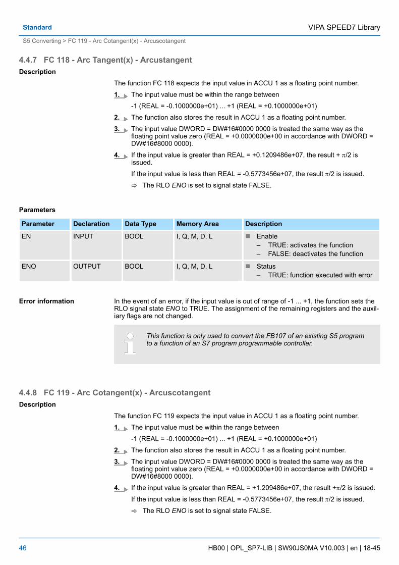
4.4.7 FC 118 - Arc Tangent(x) - Arcustangent
The function FC 118 expects the input value in ACCU 1 as a floating point number.
1. The input value must be within the range between
-1 (REAL = -0.1000000e+01) ... +1 (REAL = +0.1000000e+01)
2. The function also stores the result in ACCU 1 as a floating point number.
3. The input value DWORD = DW#16#0000 0000 is treated the same way as thefloating point value zero (REAL = +0.0000000e+00 in accordance with DWORD =DW#16#8000 0000).
4. If the input value is greater than REAL = +0.1209486e+07, the result + p/2 isissued.
If the input value is less than REAL = -0.5773456e+07, the result p/2 is issued.
ð The RLO ENO is set to signal state FALSE.
Parameters
Parameter Declaration Data Type Memory Area Description
EN INPUT BOOL I, Q, M, D, L n Enable– TRUE: activates the function– FALSE: deactivates the function
ENO OUTPUT BOOL I, Q, M, D, L n Status– TRUE: function executed with error
In the event of an error, if the input value is out of range of -1 ... +1, the function sets theRLO signal state ENO to TRUE. The assignment of the remaining registers and the auxil-iary flags are not changed.
This function is only used to convert the FB107 of an existing S5 programto a function of an S7 program programmable controller.
4.4.8 FC 119 - Arc Cotangent(x) - Arcuscotangent
The function FC 119 expects the input value in ACCU 1 as a floating point number.
1. The input value must be within the range between
-1 (REAL = -0.1000000e+01) ... +1 (REAL = +0.1000000e+01)
2. The function also stores the result in ACCU 1 as a floating point number.
3. The input value DWORD = DW#16#0000 0000 is treated the same way as thefloating point value zero (REAL = +0.0000000e+00 in accordance with DWORD =DW#16#8000 0000).
4. If the input value is greater than REAL = +1.209486e+07, the result +p/2 is issued.
If the input value is less than REAL = -0.5773456e+07, the result p/2 is issued.
ð The RLO ENO is set to signal state FALSE.
Description
Error information
Description
VIPA SPEED7 LibraryStandard
S5 Converting > FC 119 - Arc Cotangent(x) - Arcuscotangent
HB00 | OPL_SP7-LIB | SW90JS0MA V10.003 | en | 18-45 46

Parameters
Parameter Declaration Data Type Memory Area Description
EN INPUT BOOL I, Q, M, D, L n Enable– TRUE: activates the function– FALSE: deactivates the function
ENO OUTPUT BOOL I, Q, M, D, L n Status– TRUE: function executed with error
In the event of an error, if the input value is not in the range of -1 ... +1, the function setsthe RLO signal state ENO to TRUE. The assignment of the remaining registers and theauxiliary flags are not changed.
This function is only used to convert the FB 108 of an existing S5 pro-gram to a function of an S7 program programmable controller.
4.4.9 FC 120 - Naperian Logarithm In(x) - Naperian Logarithm
The function FC 120 expects the input value in accumulator 1 as a floating point number.
1. The input value must be within the range between
-1 (REAL = -0.1000000e+01) and +1 (REAL = +0.1000000e+01).
2. The function also stores the result in accumulator 1 as a floating point number.
3. If the calculation is carried out correctly, the RLO is FALSE after the function hasbeen called up.
Parameters
Parameter Declaration Data Type Memory Area Description
EN INPUT BOOL I, Q, M, D, L n Enable– TRUE: activates the function– FALSE: deactivates the function
ENO OUTPUT BOOL I, Q, M, D, L n Status– TRUE: function executed with error
In the event of an error, the function sets the ENO to signal state TRUE (if the input valueis less than or equal to zero). In this case, the contents of accumulator 1 remainunchanged. The assignment of the remaining registers and that of the auxiliary flags arenot changed.
This function is only used to convert the FB 109 of an existing S5 pro-gram to a function of an S7 program programmable controller.
Error information
Description
Error information
VIPA SPEED7 Library Standard
S5 Converting > FC 120 - Naperian Logarithm In(x) - Naperian Logarithm
HB00 | OPL_SP7-LIB | SW90JS0MA V10.003 | en | 18-45 47

4.4.10 FC 121 - Decimal Logarithm Ig(x) - Decimal Logarithm
The function FC 121 expects the input value in accumulator 1 as a bit floating pointnumber.
1. The input value must be within the range between
-1 (REAL = -0.1000000e+01) and +1 (REAL = +0.1000000e+01).
2. The function also stores the result in accumulator 1 as a floating point number.
3. If the calculation is carried out correctly, the RLO is FALSE after the function hasbeen called up.
Parameters
Parameter Declaration Data Type Memory Area Description
EN INPUT BOOL I, Q, M, D, L n Enable– TRUE: activates the function– FALSE: deactivates the function
ENO OUTPUT BOOL I, Q, M, D, L n Status– TRUE: function executed with error
In the event of an error, the function sets the ENO to signal state TRUE (if the input valueis less than or equal to zero). In this case, the contents of accumulator 1 remainunchanged. The assignment of the remaining registers and that of the auxiliary flags arenot changed.
This function is only used to convert the FB 110 of an existing S5 pro-gram to a function of an S7 program programmable controller.
4.4.11 FC 122 - Gen. Logarithm to Base b - General Logarithm Iog (x) to base b
The function FC 122 expects both the input value for the base (b) in ACCU 2 and theinput value for the antilogarithm (x) in ACCU 1 as floating point numbers.
1. Both input values must be greater than zero and in addition, the base may not havethe value +1.
2. If the calculation is carried out correctly, the result is stored in ACCU 1 as a floatingpoint number, the previous contents of ACCU 3 are in ACCU 2, and the previouscontents of ACCU 4 are in ACCU 3. The contents of ACCU 4 are not changed. Theassignment of the remaining registers and that of the auxiliary flags are notchanged.
3. In the case of a calculation without errors, the RLO ENO is FALSE after the functionhas been called up.
Description
Error information
Description
VIPA SPEED7 LibraryStandard
S5 Converting > FC 122 - Gen. Logarithm to Base b - General Logarithm Iog (x) to base b
HB00 | OPL_SP7-LIB | SW90JS0MA V10.003 | en | 18-45 48
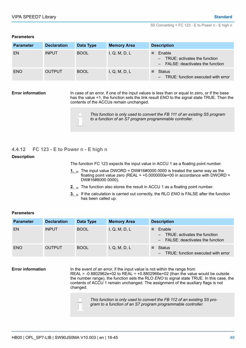
Parameters
Parameter Declaration Data Type Memory Area Description
EN INPUT BOOL I, Q, M, D, L n Enable– TRUE: activates the function– FALSE: deactivates the function
ENO OUTPUT BOOL I, Q, M, D, L n Status– TRUE: function executed with error
In case of an error, if one of the input values is less than or equal to zero, or if the basehas the value +1, the function sets the link result ENO to the signal state TRUE. Then thecontents of the ACCUs remain unchanged.
This function is only used to convert the FB 111 of an existing S5 programto a function of an S7 program programmable controller.
4.4.12 FC 123 - E to Power n - E high n
The function FC 123 expects the input value in ACCU 1 as a floating point number.
1. The input value DWORD = DW#16#0000 0000 is treated the same way as thefloating point value zero (REAL = +0.0000000e+00 in accordance with DWORD =DW#16#8000 0000).
2. The function also stores the result in ACCU 1 as a floating point number.
3. If the calculation is carried out correctly, the RLO ENO is FALSE after the functionhas been called up.
Parameters
Parameter Declaration Data Type Memory Area Description
EN INPUT BOOL I, Q, M, D, L n Enable– TRUE: activates the function– FALSE: deactivates the function
ENO OUTPUT BOOL I, Q, M, D, L n Status– TRUE: function executed with error
In the event of an error, if the input value is not within the range fromREAL = -0.8802962e+02 to REAL = +0.8802966e+02 (than the value would be outsidethe number range), the function sets the RLO ENO to signal state TRUE. In this case, thecontents of ACCU 1 remain unchanged. The assignment of the auxiliary flags is notchanged.
This function is only used to convert the FB 112 of an existing S5 pro-gram to a function of an S7 program programmable controller.
Error information
Description
Error information
VIPA SPEED7 Library Standard
S5 Converting > FC 123 - E to Power n - E high n
HB00 | OPL_SP7-LIB | SW90JS0MA V10.003 | en | 18-45 49

4.4.13 FC 124 - 10 to Power n - 10 high n
The function FC 124 expects the input value in ACCU 1 as a floating point number.
1. The input value DWORD = DW#16#0000 0000 is treated the same way as thefloating point value zero (REAL = +0.0000000e+00 in accordance with DWORD =DW#16#8000 0000).
2. The function also stores the result in ACCU 1 as a floating point number.
3. If the calculation is carried out correctly, the RLO ENO is FALSE after the functionhas been called up.
Parameters
Parameter Declaration Data Type Memory Area Description
EN INPUT BOOL I, Q, M, D, L n Enable– TRUE: activates the function– FALSE: deactivates the function
ENO OUTPUT BOOL I, Q, M, D, L n Status– TRUE: function executed with error
In the event of an error, if the input value is not within the range from -0.3823079e+02 ...REAL = + 0.3823080e+02 (than the value would be outside the number range), the func-tion sets the RLO ENO to signal state TRUE. In this case, the contents of ACCU 1 remainunchanged. The assignment of the auxiliary flags is not changed.
This function is only used to convert the FB 113 of an existing S5 pro-gram to a function of an S7 program programmable controller.
4.4.14 FC 125 - ACCU 2 to Power ACCU 1 - ACCU 2 high ACCU 1
The function FC 125 expects both the input value for the base in ACCU 2 and the inputvalue for the exponent in ACCU 1 as floating point numbers.
1. The input value for the base must be positive.
An input value DWORD = DW#16#0000 0000 is treated the same way as thefloating point value zero (REAL = +0.0000000e+00 in accordance with DWORD =DW#16#8000 0000).
For zero high zero the result is zero.
2. The function also stores the result in ACCU 1 as a floating point number.
3. If the calculation is carried out correctly, the RLO ENO is FALSE after the functionhas been called up.
Description
Error information
Description
VIPA SPEED7 LibraryStandard
S5 Converting > FC 125 - ACCU 2 to Power ACCU 1 - ACCU 2 high ACCU 1
HB00 | OPL_SP7-LIB | SW90JS0MA V10.003 | en | 18-45 50

Parameters
Parameter Declaration Data Type Memory Area Description
EN INPUT BOOL I, Q, M, D, L n Enable– TRUE: activates the function– FALSE: deactivates the function
ENO OUTPUT BOOL I, Q, M, D, L n Status– TRUE: function executed with error
If the RLO ENO is TRUE, one of the following errors has occurred:
n the input value for the base is less than zeron a number range overflow occurred during calculation of the function
In the event of an error, the contents of ACCU 1 and 2 remain unchanged.
This function is only used to convert the FB 114 of an existing S5 pro-gram to a function of an S7 program programmable controller.
4.5 PID Control4.5.1 FB 41 - CONT_C - Continuous control
FB 41 CONT_C is used to control technical processes with continuous input and outputvariables. During parameter assignment, you can activate or deactivate subfunctions ofthe PID controller to adapt the controller to the process.
Parameters
Parameter Declaration Data Type Description
COM_RST INPUT BOOL COMPLETE RESTART
n The block has a complete restart routine that is pro-cessed when the input COM_RST is set.
n Default: FALSE
MAN_ON INPUT BOOL MANUAL VALUE ON
n If the input MAN_ON is set, the control loop is inter-rupted. A manual value is set as the manipulatedvalue.
n Default: TRUE
PVPER_ON INPUT BOOL PROCESS VARIABLE PERIPHERY ON
n If the process variable is read from the I/Os, theinput PV_PER must be connected to the I/Os andthe input PVPER_ON must be set.
n Default: FALSE
P_SEL INPUT BOOL PROPORTIONAL ACTION ON
n The PID actions can be activated or deactivatedindividually in the PID algorithm. The P action is onwhen the input P_SEL is set.
n Default: TRUE
Error information
Description
VIPA SPEED7 Library Standard
PID Control > FB 41 - CONT_C - Continuous control
HB00 | OPL_SP7-LIB | SW90JS0MA V10.003 | en | 18-45 51

Parameter Declaration Data Type Description
I_SEL INPUT BOOL INTEGRAL ACTION ON
n The PID actions can be activated or deactivatedindividually in the PID algorithm. The I action is onwhen the input I_SEL is set.
n Default: TRUE
INT_HOLD INPUT BOOL INTEGRAL ACTION HOLD
n The output of the integrator can be "frozen" by set-ting the input INT_HOLD.
n Default: FALSE
I_ITL_ON INPUT BOOL INITIALIZATION OF THE INTEGRAL ACTION
n The output of the integrator can be connected tothe input I_ITL_VAL by setting the input I_ITL_ON.
n Default: FALSE
D_SEL INPUT BOOL DERIVATIVE ACTION ON
n The PID actions can be activated or deactivatedindividually in the PID algorithm. The D action is onwhen the input D_SEL is set.
n Default: FALSE
CYCLE INPUT TIME SAMPLE TIME
n The time between the block calls must be constant.The CYCLE input specifies the time between blockcalls.
n Default: T#1sn Range of Values: ³ 1ms
SP_INT INPUT REAL INTERNAL SETPOINT
n The SP_INT input is used to specify a setpoint.n Default: 0.0n Range of Values: -100.0...100. 0 (%) or phys.
value1
PV_IN INPUT REAL PROCESS VARIABLE IN
n An initialization value can be set at the PV_IN inputor an external process variable in floating pointformat can be connected.
n Default: 0.0n Range of Values: -100.0...100. 0 (%) or phys.
value1
PV_PER INPUT WORD PROCESS VARIABLE PERIPHERY
n The process variable in the I/O format is connectedto the controller at the PV_PER input.
n Default: W#16#0000
MAN INPUT REAL MANUAL VALUE
n The MAN input is used to set a manual value usingthe operator interface functions.
n Default: 0.0n Range of Values: -100.0...100. 0 (%) or phys.
value2
VIPA SPEED7 LibraryStandard
PID Control > FB 41 - CONT_C - Continuous control
HB00 | OPL_SP7-LIB | SW90JS0MA V10.003 | en | 18-45 52

Parameter Declaration Data Type Description
GAIN INPUT REAL PROPORTIONAL GAIN
n The GAIN input specifies the controller gain.n Default: 2.0n Range of Values: ³ CYCLE
TI INPUT TIME RESET TIME
n The TI input determines the time response of theintegrator.
n Default: T#20sn Range of Values: ³ CYCLE
TD INPUT TIME DERIVATIVE TIME
n The TD input determines the time response of thederivative unit.
n Default: T#10sn Range of Values: ³ CYCLE
TM_LAG INPUT TIME TIME LAG OF THE DERIVATIVE ACTION
n The algorithm of the D action includes a time lagthat can be assigned at the TM_LAG input.
n Default: T#2sn Range of Values: ³ CYCLE/2
DEADB_W INPUT REAL DEAD BAND WIDTH
n A dead band is applied to the error. The DEADB_Winput determines the size of the dead band.
n Default: 0.0n Range of Values: ³ 0.0 (%) or phys. value1
LMN_HLM INPUT REAL MANIPULATED VALUE HIGH LIMIT
n The manipulated value is always limited by anupper and lower limit. The LMN_HLM input speci-fies the upper limit.
n Default: 100.0n Range of Values: LMN_LLM ...100.0 (%) or phys.
value2
LMN_LLM INPUT REAL MANIPULATED VALUE LOW LIMIT
n The manipulated value is always limited by anupper and lower limit. The LMN_LLM input speci-fies the lower limit.
n Default: 0.0n Range of Values: -100.0... LMN_HLM (%) or phys.
value2
PV_FAC INPUT REAL PROCESS VARIABLE FACTOR
n The PV_FAC input is multiplied by the process vari-able. The input is used to adapt the process vari-able range.
n Default: 1.0
VIPA SPEED7 Library Standard
PID Control > FB 41 - CONT_C - Continuous control
HB00 | OPL_SP7-LIB | SW90JS0MA V10.003 | en | 18-45 53
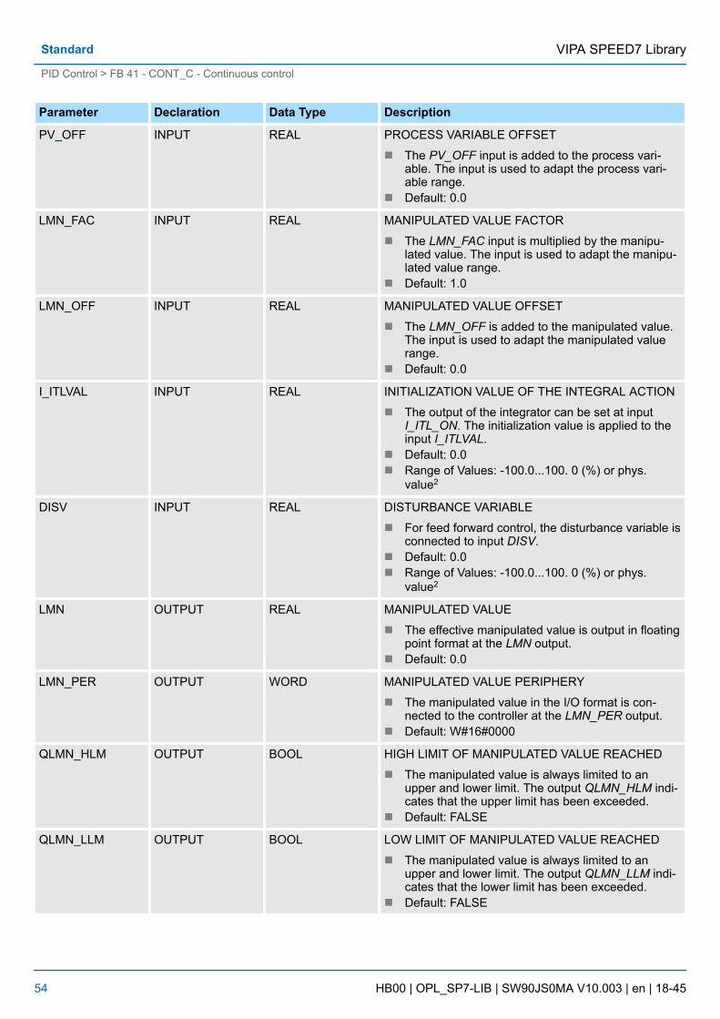
Parameter Declaration Data Type Description
PV_OFF INPUT REAL PROCESS VARIABLE OFFSET
n The PV_OFF input is added to the process vari-able. The input is used to adapt the process vari-able range.
n Default: 0.0
LMN_FAC INPUT REAL MANIPULATED VALUE FACTOR
n The LMN_FAC input is multiplied by the manipu-lated value. The input is used to adapt the manipu-lated value range.
n Default: 1.0
LMN_OFF INPUT REAL MANIPULATED VALUE OFFSET
n The LMN_OFF is added to the manipulated value.The input is used to adapt the manipulated valuerange.
n Default: 0.0
I_ITLVAL INPUT REAL INITIALIZATION VALUE OF THE INTEGRAL ACTION
n The output of the integrator can be set at inputI_ITL_ON. The initialization value is applied to theinput I_ITLVAL.
n Default: 0.0n Range of Values: -100.0...100. 0 (%) or phys.
value2
DISV INPUT REAL DISTURBANCE VARIABLE
n For feed forward control, the disturbance variable isconnected to input DISV.
n Default: 0.0n Range of Values: -100.0...100. 0 (%) or phys.
value2
LMN OUTPUT REAL MANIPULATED VALUE
n The effective manipulated value is output in floatingpoint format at the LMN output.
n Default: 0.0
LMN_PER OUTPUT WORD MANIPULATED VALUE PERIPHERY
n The manipulated value in the I/O format is con-nected to the controller at the LMN_PER output.
n Default: W#16#0000
QLMN_HLM OUTPUT BOOL HIGH LIMIT OF MANIPULATED VALUE REACHED
n The manipulated value is always limited to anupper and lower limit. The output QLMN_HLM indi-cates that the upper limit has been exceeded.
n Default: FALSE
QLMN_LLM OUTPUT BOOL LOW LIMIT OF MANIPULATED VALUE REACHED
n The manipulated value is always limited to anupper and lower limit. The output QLMN_LLM indi-cates that the lower limit has been exceeded.
n Default: FALSE
VIPA SPEED7 LibraryStandard
PID Control > FB 41 - CONT_C - Continuous control
HB00 | OPL_SP7-LIB | SW90JS0MA V10.003 | en | 18-45 54

Parameter Declaration Data Type Description
LMN_P OUTPUT REAL PROPORTIONALITY COMPONENT
n The LMN_P output contains the proportional com-ponent of the manipulated variable.
n Default: 0.0
LMN_I OUTPUT REAL INTEGRAL COMPONENT
n The LMN_I output contains the integral componentof the manipulated value.
n Default: 0.0
LMN_D OUTPUT REAL DERIVATIVE COMPONENT
n The LMN_D output contains the derivative compo-nent of the manipulated value..
n Default: 0.0
PV OUTPUT REAL PROCESS VARIABLE
n The effective process variable is output at the PVoutput.
n Default: 0.0
ER OUTPUT REAL ERROR SIGNAL
n The effective error is output at the ER output.n Default: 0.0
1) Parameters in the setpoint and process variable branches with the same unit
2) Parameters in the manipulated value branch with the same unit
You can use the controller as a PID fixed setpoint controller or in multi-loop controls as acascade, blending or ratio controller. The functions of the controller are based on the PIDcontrol algorithm of the sampling controller with an analog signal, if necessary extendedby including a pulse generator stage to generate pulse duration modulated output signalsfor two or three step controllers with proportional actuators.
Apart from the functions in the setpoint and process value branches, the FB implements acomplete PID controller with continuous manipulated variable output and the option ofinfluencing the manipulated value manually.
The setpoint is entered in floating-point format at the SP_INT input.
The process variable can be input in the peripheral (I/O) or floating-point format. TheCRP_IN function converts the PV_PER peripheral value to a floating-point format of-100 to +100 % according to the following formula:
The PV_NORM function normalizes the output of CRP_IN according to the following for-mula:
PV_FAC has a default of 1 and PV_OFF a default of 0.
Application
Setpoint Branch
Process Variable Branch
VIPA SPEED7 Library Standard
PID Control > FB 41 - CONT_C - Continuous control
HB00 | OPL_SP7-LIB | SW90JS0MA V10.003 | en | 18-45 55

The difference between the setpoint and process variable is the error signal. To suppressa small constant oscillation due to the manipulated variable quantization (for example inpulse duration modulation with PULSEGEN), a dead band is applied to the error signal(DEADBAND). If DEADB_W = 0, the dead band is switched off.
The PID algorithm operates as a position algorithm. The proportional, integral (INT), andderivative (DIF) actions are connected in parallel and can be activated or deactivatedindividually. This allows P, PI, PD, and PID controllers to be configured. Pure I and D con-trollers are also possible.
It is possible to switch over between a manual and an automatic mode. In the manualmode, the manipulated variable is corrected to a manually selected value. The integrator(INT) is set internally to LMN - LMN_P - DISV and the derivative unit (DIF) to 0 andmatched internally. This means that a switchover to the automatic mode does not causeany sudden change in the manipulated value.
The manipulated value can be limited to a selected value using the LMNLIMIT function.Signaling bits indicate when a limit is exceeded by the input variable. The LMN_NORMfunction normalizes the output of LMNLIMIT according to the following formula:
LMN_FAC has the default 1 and LMN_OFF the default 0.
The manipulated value is also available in the peripheral format. The CRP_OUT functionconverts the floating-point value LMN to a peripheral value according to the following for-mula:
A disturbance variable can be fed forward at the DISV input.
Complete Restart/Restart
n FB 41 CONT_C has a complete restart routine that is run through when the inputparameter COM_RST = TRUE is set.
n During startup, the integrator is set internally to the initialization value I_ITVAL. Whenit is called in a cyclic interrupt priority class, it then continues to work starting at thisvalue.
n All other outputs are set to their default values.
The block does not check for errors, so no error Information is output.
Error Signal
PID Algorithm
Manual Value
Manipulated Value
Feedforward Control
Modes
Error Information
VIPA SPEED7 LibraryStandard
PID Control > FB 41 - CONT_C - Continuous control
HB00 | OPL_SP7-LIB | SW90JS0MA V10.003 | en | 18-45 56

4.5.2 FB 42 - CONT_S - Step ControlFB42 CONT_S is used to control technical processes with digital manipulated valueoutput signals for integrating actuators. During parameter assignment, you can activate ordeactivate subfunctions of the PI step controller to adapt the controller to the process.
Block Diagram
Description
VIPA SPEED7 Library Standard
PID Control > FB 42 - CONT_S - Step Control
HB00 | OPL_SP7-LIB | SW90JS0MA V10.003 | en | 18-45 57

Parameter
Parameter Declaration Data Type Description
COM_RST INPUT BOOL COMPLETE RESTART
n The block has a complete restart routine that is pro-cessed when the input COM_RST is set.
n Default: FALSE
LMNR_HS INPUT BOOL HIGH LIMIT SIGNAL OF REPEATED MANIPULATEDVALUE
n The "actuator at upper limit stop" signal is con-nected to the LMNR_HS input.– LMNR_HS = TRUE means the actuator is at
upper limit stop.n Default: FALSE
LMNR_LS INPUT BOOL LOW LIMIT SIGNAL OF REPEATED MANIPULATEDVALUE
n The "actuator at lower limit stop" signal is con-nected to the LMNR_LS input.– LMNR_LS = TRUE means the actuator is at
lower limit stop.n Default: FALSE
LMNS_ON INPUT BOOL MANIPULATED SIGNALS ON
n The actuating signal processing is switched tomanual at the LMNS_ON input..
n Default: FALSE
LMNUP INPUT BOOL MANIPULATED SIGNALS UP
n With manual actuating value signals, the outputsignal QLMNUP is set at the input LMNUP.
n Default: FALSE
LMNDN INPUT BOOL MANIPULATED SIGNALS DOWN
n With manual actuating value signals, the outputsignal QLMNDN is set at the input LMNDN.
n Default: FALSE
PVPER_ON INPUT BOOL PROCESS VARIABLE PERIPHERY ON
n If the process variable is read in from the I/Os, theinput PV_PER must be connected to the I/Os andthe input PVPER_ON must be set.
n Default: FALSE
CYCLE INPUT TIME SAMPLE TIME
n The time between the block calls must be constant.The CYCLE input specifies the time between blockcalls.
n Default: T#1sn Range of Values: ³ 1ms
SP_INT INPUT REAL INTERNAL SETPOINT
n The SP_INT input is used to specify a setpoint.n Default: 0.0n Range of Values: -100.0...100. 0 (%) or phys.
value1
VIPA SPEED7 LibraryStandard
PID Control > FB 42 - CONT_S - Step Control
HB00 | OPL_SP7-LIB | SW90JS0MA V10.003 | en | 18-45 58

Parameter Declaration Data Type Description
PV_IN INPUT REAL PROCESS VARIABLE IN
n An initialization value can be set at the PV_IN inputor an external process variable in floating pointformat can be connected.
n Default: 0.0n Range of Values: -100.0...100. 0 (%) or phys.
value1
PV_PER INPUT WORD PROCESS VARIABLE PERIPHERY
n The process variable in the I/O format is connectedto the controller at the PV_PER input.
n Default: W#16#0000
GAIN INPUT REAL PROPORTIONAL GAIN
n The GAIN input sets the controller gain.n Default: 2.0n Range of Values: ³ CYCLE
TI INPUT TIME RESET TIME
n The TI input determines the time response of theintegrator.
n Default: T#20sn Range of Values: ³ CYCLE
DEADB_W INPUT REAL DEAD BAND WIDTH
n A dead band is applied to the error. The DEADB_Winput determines the size of the dead band.
n Default: 1.0n Range of Values: 0.0...100.0 (%) or phys. value1
PV_FAC INPUT REAL PROCESS VARIABLE FACTOR
n The PV_FAC input is multiplied by the process vari-able. The input is used to adapt the process vari-able range.
n Default: 1.0
PV_OFF INPUT REAL PROCESS VARIABLE OFFSET
n The PV_OFF input is added to the process vari-able. The input is used to adapt the process vari-able range.
n Default: 0.0
PULSE_TM INPUT TIME MINIMUM PULSE TIME
n A minimum pulse duration can be assigned with theparameter PULSE_TM.
n Default: T#3sn Range of Values: ³ CYCLE
BREAK_TM INPUT TIME MINIMUM BREAK TIME
n A minimum break duration can be assigned withthe parameter BREAK_TM.
n Default: T#3sn Range of Values: ³ CYCLE
VIPA SPEED7 Library Standard
PID Control > FB 42 - CONT_S - Step Control
HB00 | OPL_SP7-LIB | SW90JS0MA V10.003 | en | 18-45 59

Parameter Declaration Data Type Description
MTR_TM INPUT TIME MOTOR MANIPULATED VALUE
n The time required by the actuator to move fromlimit stop to limit stop is entered at the MTR_TMparameter.
n Default: T#30sn Range of Values: ³ CYCLE
DISV INPUT REAL DISTURBANCE VARIABLE
n For feed forward control, the disturbance variable isconnected to input DISV.
n Default: 0.0n Range of Values: -100.0...100. 0 (%) or phys.
value2
QLMNUP OUTPUT BOOL MANIPULATED SIGNAL UP
n If the output QLMNUP is set, the actuating valve isopened.
n Default: FALSE
QLMNDN OUTPUT BOOL MANIPULATED SIGNAL DOWN
n If the output QLMNDN is set, the actuating valve isopened.
n Default: FALSE
PV OUTPUT REAL PROCESS VARIABLE
n The effective process variable is output at the PVoutput.
n Default: 0.0
ER OUTPUT REAL ERROR SIGNAL
n The effective error is output at the ER output.n Default: 0.0
1) Parameters in the setpoint and process variable branches with the same unit
2) Parameters in the manipulated value branch with the same unit
You can use the controller as a PI fixed setpoint controller or in secondary control loops incascade, blending or ratio controllers, however not as the primary controller. The func-tions of the controller are based on the PI control algorithm of the sampling controller sup-plemented by the functions for generating the binary output signal from the analogactuating signal.
Apart from the functions in the process value branch, the FB implements a complete PIcontroller with a digital manipulated value output and the option of influencing the manip-ulated value manually. The step controller operates without a position feedback signal.
The setpoint is entered in floating-point format at the SP_INT input.
The process variable can be input in the peripheral (I/O) or floating-point format. TheCRP_IN function converts the PV_PER peripheral value to a floating-point format of -100to +100 % according to the following formula:
Application
Setpoint Branch
Process Variable Branch
VIPA SPEED7 LibraryStandard
PID Control > FB 42 - CONT_S - Step Control
HB00 | OPL_SP7-LIB | SW90JS0MA V10.003 | en | 18-45 60

The PV_NORM function normalizes the Output of CRP_IN following formula:
PV_FAC has a default of 1 and PV_OFF a default of 0.
The difference between the setpoint and process variable is the error signal. To suppressa small constant oscillation due to the manipulated variable quantization (for example dueto a limited resolution of the manipulated value by the actuator valve), a dead band isapplied to the error signal (DEADBAND). If DEADB_W = 0, the dead band is switched off.
The FB operates without a position feedback signal. The I action of the PI algorithm andthe assumed position feedback signal are calculated in one integrator (INT) and com-pared with the remaining P action as a feedback value. The difference is applied to athree-step element (THREE_ST) and a pulse generator (PULSEOUT) that creates thepulses for the actuator. The switching frequency of the controller can be reduced byadapting the threshold on of the three-step element.
A disturbance variable can be fed forward at the DISV input.
Complete Restart/Restart
n FB42 CONT_S has a complete restart routine that is run through when the inputparameter COM_RST = TRUE is set.
n All other outputs are set to their default values.
The block does not check for errors, so no error Information is output.
Error Signal
PI Step Algorithm
Feedforward Control
Modes
Error Information
VIPA SPEED7 Library Standard
PID Control > FB 42 - CONT_S - Step Control
HB00 | OPL_SP7-LIB | SW90JS0MA V10.003 | en | 18-45 61

4.5.3 FB 43 - PULSGEN - Pulse generationFB 43 PULSEGEN is used to structure a PID controller with pulse output for proportionalactuators. Using FB43, PID two or three step controllers with pulse duration modulationcan be configured. The function is normally used in conjunction with the continuous con-troller CONT_C.
Block Diagram
Description
VIPA SPEED7 LibraryStandard
PID Control > FB 43 - PULSGEN - Pulse generation
HB00 | OPL_SP7-LIB | SW90JS0MA V10.003 | en | 18-45 62
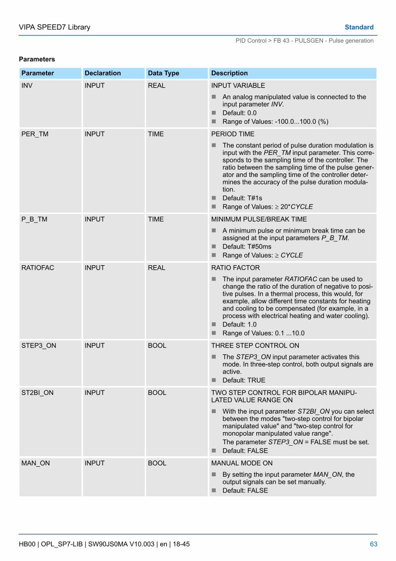
Parameters
Parameter Declaration Data Type Description
INV INPUT REAL INPUT VARIABLE
n An analog manipulated value is connected to theinput parameter INV.
n Default: 0.0n Range of Values: -100.0...100.0 (%)
PER_TM INPUT TIME PERIOD TIME
n The constant period of pulse duration modulation isinput with the PER_TM input parameter. This corre-sponds to the sampling time of the controller. Theratio between the sampling time of the pulse gener-ator and the sampling time of the controller deter-mines the accuracy of the pulse duration modula-tion.
n Default: T#1sn Range of Values: ³ 20*CYCLE
P_B_TM INPUT TIME MINIMUM PULSE/BREAK TIME
n A minimum pulse or minimum break time can beassigned at the input parameters P_B_TM.
n Default: T#50msn Range of Values: ³ CYCLE
RATIOFAC INPUT REAL RATIO FACTOR
n The input parameter RATIOFAC can be used tochange the ratio of the duration of negative to posi-tive pulses. In a thermal process, this would, forexample, allow different time constants for heatingand cooling to be compensated (for example, in aprocess with electrical heating and water cooling).
n Default: 1.0n Range of Values: 0.1 ...10.0
STEP3_ON INPUT BOOL THREE STEP CONTROL ON
n The STEP3_ON input parameter activates thismode. In three-step control, both output signals areactive.
n Default: TRUE
ST2BI_ON INPUT BOOL TWO STEP CONTROL FOR BIPOLAR MANIPU-LATED VALUE RANGE ON
n With the input parameter ST2BI_ON you can selectbetween the modes "two-step control for bipolarmanipulated value" and "two-step control formonopolar manipulated value range".The parameter STEP3_ON = FALSE must be set.
n Default: FALSE
MAN_ON INPUT BOOL MANUAL MODE ON
n By setting the input parameter MAN_ON, theoutput signals can be set manually.
n Default: FALSE
VIPA SPEED7 Library Standard
PID Control > FB 43 - PULSGEN - Pulse generation
HB00 | OPL_SP7-LIB | SW90JS0MA V10.003 | en | 18-45 63
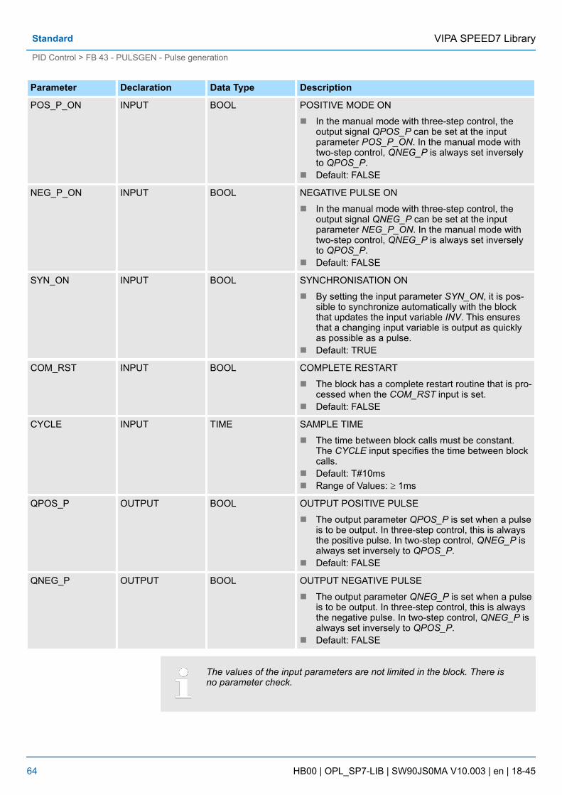
Parameter Declaration Data Type Description
POS_P_ON INPUT BOOL POSITIVE MODE ON
n In the manual mode with three-step control, theoutput signal QPOS_P can be set at the inputparameter POS_P_ON. In the manual mode withtwo-step control, QNEG_P is always set inverselyto QPOS_P.
n Default: FALSE
NEG_P_ON INPUT BOOL NEGATIVE PULSE ON
n In the manual mode with three-step control, theoutput signal QNEG_P can be set at the inputparameter NEG_P_ON. In the manual mode withtwo-step control, QNEG_P is always set inverselyto QPOS_P.
n Default: FALSE
SYN_ON INPUT BOOL SYNCHRONISATION ON
n By setting the input parameter SYN_ON, it is pos-sible to synchronize automatically with the blockthat updates the input variable INV. This ensuresthat a changing input variable is output as quicklyas possible as a pulse.
n Default: TRUE
COM_RST INPUT BOOL COMPLETE RESTART
n The block has a complete restart routine that is pro-cessed when the COM_RST input is set.
n Default: FALSE
CYCLE INPUT TIME SAMPLE TIME
n The time between block calls must be constant.The CYCLE input specifies the time between blockcalls.
n Default: T#10msn Range of Values: ³ 1ms
QPOS_P OUTPUT BOOL OUTPUT POSITIVE PULSE
n The output parameter QPOS_P is set when a pulseis to be output. In three-step control, this is alwaysthe positive pulse. In two-step control, QNEG_P isalways set inversely to QPOS_P.
n Default: FALSE
QNEG_P OUTPUT BOOL OUTPUT NEGATIVE PULSE
n The output parameter QNEG_P is set when a pulseis to be output. In three-step control, this is alwaysthe negative pulse. In two-step control, QNEG_P isalways set inversely to QPOS_P.
n Default: FALSE
The values of the input parameters are not limited in the block. There isno parameter check.
VIPA SPEED7 LibraryStandard
PID Control > FB 43 - PULSGEN - Pulse generation
HB00 | OPL_SP7-LIB | SW90JS0MA V10.003 | en | 18-45 64

The PULSEGEN function transforms the input variable INV ( = manipulated value of thePID controller) by modulating the pulse duration into a pulse train with a constant period,corresponding to the cycle time at which the input variable is updated and which must beassigned in PER_TM. The duration of a pulse per period is proportional to the input vari-able. The cycle assigned to PER_TM is not identical to the processing cycle of the FBPULSEGEN. The PER_TM cycle is made up of several processing cycles of FB PUL-SEGEN, whereby the number of FB PULSEGEN calls per PER_TM cycle is the yardstickfor the accuracy of the pulse duration modulation.
An input variable of 30% and 10 FB PULSEGEN calls per PER_TM means the following:
n "1" at the QPOS output for the first three calls of FB PULSEGEN (30% of 10 calls)n "0" at the QPOS output for seven further calls of FB PULSEGEN (70% of 10 calls)
With a "sampling ratio" of 1:10 (CONT_C calls to PULSEGEN calls) the accuracy of themanipulated value in this example is restricted to 10 %, in other words, set input valuesINV can only be simulated by a pulse duration at the QPOS output in steps of 10 %. Theaccuracy is increased as the number of FB PULSEGEN calls per CONT_C call isincreased. If PULSEGEN is called, for example 100 times more often than CONT_C, aresolution of 1 % of the manipulated value range is achieved.
Application
Block Diagram
Accuracy of the Manipu-lated Value
VIPA SPEED7 Library Standard
PID Control > FB 43 - PULSGEN - Pulse generation
HB00 | OPL_SP7-LIB | SW90JS0MA V10.003 | en | 18-45 65

The call frequency must be programmed by the user.
It is possible to synchronize the pulse output with the block that updates the input variableINV (for example CONT_C). This ensures that a change in the input variable is output asquickly as possible as a pulse. The pulse generator evaluates the input value INV at inter-vals corresponding to the period PER_TM and converts the value into a pulse signal ofcorresponding length. Since, however, INV is usually calculated in a slower cyclic inter-rupt class, the pulse generator should start the conversion of the discrete value into apulse signal as soon as possible after the updating of INV. To allow this, the block cansynchronize the start of the period using the following procedure:
n If INV changes and if the block call is not in the first or last two call cycles of a period,the synchronization is performed. The pulse duration is recalculated and in the nextcycle is output with a new period.
The automatic synchronization can be disabled at the SYN_ON input (= FALSE).
With the beginning of a new period, the old value of INV (in other words,of LMN) is simulated in the pulse signal more or less accurately followingthe synchronization.
Depending on the parameters assigned to the pulse generator, PID controllers with athree-step output or with a bipolar or monopolar two-step output can be configured. Thefollowing table illustrates the setting of the switch combinations for the possible modes.
Automatic Synchroniza-tion
Modes
VIPA SPEED7 LibraryStandard
PID Control > FB 43 - PULSGEN - Pulse generation
HB00 | OPL_SP7-LIB | SW90JS0MA V10.003 | en | 18-45 66

Mode Switch
MAN_ON STEP3_ON ST2BI_ON
Three-step control FALSE TRUE Any
Two-step control with bipolar control range(-100 % to +100 %)
FALSE FALSE TRUE
Two-step control with monopolar controlrange (0 % ... 100 %)
FALSE FALSE FALSE
Manual mode TRUE Any Any
In the three-step control mode, the actuating signal can adopt three states. The values ofthe binary output signals QPOS_P and QNEG_P are assigned to the statuses of theactuator. The table shows the example of a temperature control:
Output signal Actuator
Heat Off Cool
QPOS_P TRUE FALSE FALSE
QNEG_P FALSE FALSE TRUE
Based on the input variable, a characteristic curve is used to calculate a pulse duration.The form of the characteristic curve is defined by the minimum pulse or minimum breaktime and the ratio factor. The normal value for the ratio factor is 1. The “doglegs” in thecurves are caused by the minimum pulse or minimum break times.
n Minimum Pulse or Minimum Break TimeA correctly assigned minimum pulse or minimum break time P_B_TM can preventshort on/off times that reduce the working life of switching elements and actuators.
Small absolute values at the input variable LMN that could otherwise gen-erate a pulse duration shorter than P_B_TM are suppressed. Large inputvalues that would generate a pulse duration longer than (PER_TM -P_B_TM) are set to 100 % or -100 %.
The positive and negative pulse duration is calculated by multiplying the input variable (in%) with the period time:
Three-Step Control
VIPA SPEED7 Library Standard
PID Control > FB 43 - PULSGEN - Pulse generation
HB00 | OPL_SP7-LIB | SW90JS0MA V10.003 | en | 18-45 67

Using the ratio factor RATIOFAC, the ratio of the duration of positive to negative pulsescan be changed. In a thermal process, for example, this would allow different system timeconstants for heating and cooling. The ratio factor also influences the minimum pulse orminimum break time. A ratio factor < 1 means that the threshold value for negative pulsesis multiplied by the ratio factor.
n Ratio Factor < 1The pulse duration at the negative pulse output calculated from the input variablemultiplied by the period time is reduced by the ratio factor.
Three-Step Control Asym-metrical
VIPA SPEED7 LibraryStandard
PID Control > FB 43 - PULSGEN - Pulse generation
HB00 | OPL_SP7-LIB | SW90JS0MA V10.003 | en | 18-45 68

n Ratio Factor > 1The pulse duration at the positive pulse output calculated from the input variable mul-tiplied by the period time is reduced by the ratio factor.
In two-step control, only the positive pulse output QPOS_P of PULSEGEN is connectedto the on/off actuator. Depending on the manipulated value range being used, the two-step controller has a bipolar or a monopolar manipulated value range.
n Two-Step Control with Bipolar Manipulated Variable Range (-100 % to 100 %)
n Two-Step Control with Monopolar Manipulated Variable Range (0 % to 100 %)
The negated output signal is available at QNEG_P if the connection of the two-step con-troller in the control loop requires a logically inverted binary signal for the actuatingpulses.
Pulse Actuator
On Off
QPOS_P TRUE FALSE
QNEG_P FALSE TRUE
In the manual mode (MAN_ON = TRUE), the binary outputs of the three-step or two-stepcontroller can be set using the signals POS_P_ON and NEG_P_ON regardless of INV.
Two-Step Control
Manual Mode in Two/Three-Step Control
VIPA SPEED7 Library Standard
PID Control > FB 43 - PULSGEN - Pulse generation
HB00 | OPL_SP7-LIB | SW90JS0MA V10.003 | en | 18-45 69

POS_P_ON NEG_P_ON QPOS_P QNEG_P
Three-step con-trol
FALSE FALSE FALSE FALSE
TRUE FALSE TRUE FALSE
FALSE TRUE FALSE TRUE
TRUE TRUE FALSE FALSE
Two-step con-trol
FALSE Any FALSE TRUE
TRUE Any TRUE FALSE
Complete Restart/Restart
n During a complete restart, all the signal outputs are set to 0.
The block does not check for errors, so no error Information is output.
4.5.4 FB 58 - TCONT_CP - Continuous Temperature ControlFB 58 TCONT_CP is used to control temperature processes with continuous or pulsedcontrol signals. You can set parameters to enable or disable subfunctions of the PID con-troller and adapt it to the process.
Parameters
Parameter Declaration Data Type Description
PV_IN INPUT REAL PROCESS VARIABLE IN
n An initialization value can be set at the PV_IN inputor an external process variable in floating-pointformat can be connected.
n Default: 0.0n Dependent on the sensors used
PV_PER INPUT WORD PROCESS VARIABLE PERIPHERY
n The process variable in the peripheral I/O format isconnected to the controller at the PV_PER input.
n Default: 0
DISV INPUT REAL DISTURBANCE VARIABLE
n For feed forward control, the disturbance variable isconnected to the DISV input.
n Default: 0.0
INT_HPOS INPUT BOOL INTEGRAL ACTION HOLD IN POSITIVE DIRECTION
n The output of the integral action can be blocked ina positive direction. To achieve this, the INT_HPOSinput must be set to TRUE. In a cascade control,the INT_HPOS of the primary controller is intercon-nected to QLMN_HLM of the secondary controller.
n Default: FALSE
Modes
Error Information
Description
VIPA SPEED7 LibraryStandard
PID Control > FB 58 - TCONT_CP - Continuous Temperature Control
HB00 | OPL_SP7-LIB | SW90JS0MA V10.003 | en | 18-45 70

Parameter Declaration Data Type Description
INT_HNEG INPUT BOOL INTEGRAL ACTION HOLD IN NEGATIVE DIRECTION
n The output of the integral action can be blocked ina positive direction. To achieve this, the INT_HPOSinput must be set to TRUE. In a cascade control,the INT_HPOS of the primary controller is intercon-nected to QLMN_HLM of the secondary controller.
n Default: FALSE
SELECT INPUT BOOL SELECTION OF CALL PID AND PULSE GENERATOR
n If the pulse generator is activated, there are severalways of calling the PID algorithm and pulse gener-ator:– SELECT = 0: The controller is called in a fast
cyclic interrupt level and the PID algorithm andpulse generator are processed.
– SELECT = 1: The controller is called in OB1and only the PID algorithm is processed.
– SELECT = 2: The controller is called in a fastcyclic interrupt level and only the pulse gener-ator is processed.
– SELECT = 3: The controller is called in a slowcyclic interrupt level only the PID algorithm isprocessed.
n Default: 0n Range of Values: 0 ... 3
PV OUTPUT REAL PROCESS VARIABLE
n The effective process variable is output at the PVoutput.
n Default: 0.0n Range of Values: Dependent on the sensors used
LMN OUTPUT REAL MANIPULATED VALUE
n The effective value of the manipulated variable isoutput in floating-point format at the LMN output.
n Default: 0.0
LMN_PER OUTPUT WORD MANIPULATED VALUE PERIPHERY
n The value of the manipulated variable in the periph-eral format is connected to the controller at theLMN_PER output.
n Default: 0
QPULSE OUTPUT BOOL QUTPUT PULSE SIGNAL
n The value of the manipulated variable is outputpulse duration modulated at the QPULSE output.
n Default: FALSE
QLMN_HLM OUTPUT BOOL HIGH LIMIT OF MANIPULATED VALUE REACHED
n The value of the manipulated variable is alwayslimited to an upper and lower limit. TheQLMN_HLM output indicates when the upper limitis exceeded.
n Default: FALSE
VIPA SPEED7 Library Standard
PID Control > FB 58 - TCONT_CP - Continuous Temperature Control
HB00 | OPL_SP7-LIB | SW90JS0MA V10.003 | en | 18-45 71

Parameter Declaration Data Type Description
QLMN_LLM OUTPUT BOOL LOW LIMIT OF MANIPULATED VALUE REACHED
n The value of the manipulated variable is alwayslimited to an upper and lower limit. The QLMN_LLMoutput indicates when the lower limit is exceeded.
n Default: FALSE
QC_ACT OUTPUT BOOL NEXT CYCLE, THE CONTINUOUS CONTROLLER ISWORKING
n This parameter indicates whether or not the contin-uous controller stage will be executed at the nextblock call (relevant only when SELECT has thevalue 0 or 1).
n Default: TRUE
CYCLE INPUT/ OUTPUT REAL SAMPLE TIME OF CONTINUOUS CONTROLLER [s]
n This sets the sampling time for the PID algorithm.The tuner calculates the sampling time in Phase 1and enters this in CYCLE.
n Default: 0.1sn Range of Values: ³ 1ms
CYCLE_P INPUT/ OUTPUT REAL SAMPLE TIME OF PULSE GENERATOR [s]
n At this input, you enter the sampling time for thepulse generator stage. FB 58 "TCONT_CP" calcu-lates the sampling time in Phase 1 and enters it inCYCLE_P.
n Default: 0.2sn Range of Values: ³ 1ms
SP_INT INPUT/ OUTPUT REAL INTERNAL SETPOINT
n The SP_INT input is used to specify a setpoint.n Default: 0.0n Range of Values: Value range of the process value
MAN INPUT/ OUTPUT REAL MANUAL VALUE
n The MAN input is used to specify a manual value.In automatic mode, it is corrected to the manipu-lated variable.
n Default: 0.0
COM_RST INPUT/ OUTPUT REAL COMPLETE RESTART
n The block has an initialization routine that is pro-cessed when the COM_RST input is set.
n Default: FALSE
MAN_ON INPUT/ OUTPUT REAL MANUAL OPERATION ON
n If the MAN_ON input is set, the control loop is inter-rupted. The MAN manual value is set as the valueof the manipulated variable.
n Default: TRUE
VIPA SPEED7 LibraryStandard
PID Control > FB 58 - TCONT_CP - Continuous Temperature Control
HB00 | OPL_SP7-LIB | SW90JS0MA V10.003 | en | 18-45 72

Internal Parameters
Parameter Declaration Data type Description
DEADB_W INPUT REAL DEAD BAND WIDTH
n The error passes through a dead band. TheDEADB_W input decides the size of the deadband.
n Default: 0.0n Range of Values: Dependent on the sensors used
I_ITLVAL INPUT REAL INITIALIZATION VALUE OF THE INTEGRAL ACTION
n The output of the integral action can be set at theI_ITL_ON input. The initialization value is applied tothe I_ITLVAL input.
n During a restart COM_RST = TRUE, the I action isset to the initialization value.
n Default: 0.0n Range of Values: 0 to 100 %
LMN_HLM INPUT REAL MANIPULATED VARIABLE HIGH LIMIT
n The value of the manipulated variable is alwayslimited to an upper and lower limit. The LMN_HLMinput specifies the upper limit.
n Default: 100.0n Range of Values: > LMN_ LLM
LMN_LLM INPUT REAL MANIPULATED VARIABLE LOW LIMIT
n The value of the manipulated variable is alwayslimited to an upper and lower limit. The LMN_LLMinput specifies the lower limit.
n Default: 0.0n Range of Values: < LMN_HLM
PV_FAC INPUT REAL PROCESS VARIABLE FACTOR
n The PV_FAC input is multiplied by the PV_PER.The input is used to adapt the process variablerange.
n Default: 1.0
PV_OFFS INPUT REAL PROCESS VARIABLE OFFSET
n The PV_OFFS input is added to the PV_PER. Theinput is used to adapt the process variable range.
n Default: 0.0
LMN_FAC INPUT REAL MANIPULATED VARIABLE FACTOR
n The LMN_FAC input is multiplied by the manipu-lated variable. The input is used to adapt themanipulated variable range.
n Default: 1.0
LMN_OFFS INPUT REAL MANIPULATED VARIABLE OFFSET
n The LMN_OFFS input is added to the value of themanipulated variable. The input is used to adaptthe manipulated variable range.
n Default: 0.0
VIPA SPEED7 Library Standard
PID Control > FB 58 - TCONT_CP - Continuous Temperature Control
HB00 | OPL_SP7-LIB | SW90JS0MA V10.003 | en | 18-45 73

Parameter Declaration Data type Description
PER_TM INPUT REAL PERIOD TIME [s]
n The pulse repetition period of the pulse durationmodulation is entered at the PER_TM parameter.The relationship of the pulse repetition period to thesampling time of the pulse generator decides theaccuracy of the pulse duration modulation.
n Default: 1.0 sn Range of Values: ³ CYCLE
P_B_TM INPUT REAL MINIMUM PULSE/BREAK TIME [s]
n A minimum pulse or minimum break time can beset at the P_B_TM parameter. P_B_TM is limitedinternally to > CYCLE_P.
n Default: 0.02 sn Range of Values: ³ 0.0
TUN_DLMN INPUT REAL DELTA MANIPULATED VARIABLE FOR PROCESSEXCITATION
n Process excitation for controller tuning results froma setpoint step change at TUN_DLMN.
n Default: 20.0n Range of Values: -100.0 ... 100.0 %
PER_MODE INPUT INT PERIPHERY MODE
n You can enter the type of the I/O module at thisswitch. The process variable at input PV_PER isthen normalized to °C at the PV output.– PER_MODE = 0: standard– PER_MODE = 1: climate– PER_MODE = 2: current/voltage
n Default: 0n Range of Values: 0, 1, 2
PVPER_ON INPUT BOOL PROCESS VARIABLE PERIPHERY ON
n If you want the process variable to be read in fromthe I/O, the PV_PER input must be connected tothe I/O and the PVPER_ON input must be set.
n Default: FALSE
I_ITL_ON INPUT BOOL INITIALIZATION OF THE INTEGRAL ACTION ON
n The output of the integral action can be set to theI_ITLVAL input. The I_ITL_ON input must be set.
n Default: FALSE
PULSE_ON INPUT BOOL PULSE GENERATOR ON
n If PULSE_ON = TRUE is set, the pulse generator isactivated
n Default: FALSE
TUN_KEEP INPUT BOOL KEEP TUNING ON
n The mode changes to automatic only whenTUN_KEEP changes to FALSE.
n Default: FALSE
VIPA SPEED7 LibraryStandard
PID Control > FB 58 - TCONT_CP - Continuous Temperature Control
HB00 | OPL_SP7-LIB | SW90JS0MA V10.003 | en | 18-45 74

Parameter Declaration Data type Description
ER OUTPUT REAL ERROR SIGNAL
n The effective error is output at the ER output.n Default: 0.0n Range of Values: Dependent on the sensors used
LMN_P OUTPUT REAL PROPORTIONALITY COMPONENT
n The LMN_P contains the proportional action of themanipulated variable.
n Default: 0.0
LMN_I OUTPUT REAL INTEGRAL COMPONENT
n The LMN_I contains the integral action of themanipulated variable.
n Default: 0.0
LMN_D OUTPUT REAL DERIVATIVE COMPONENT
n The LMN_D contains the derivative action of themanipulated variable.
n Default: 0.0
PHASE OUTPUT INT PHASE OF SELF TUNING
n The current phase of the controller tuning is indi-cated at the PHASE output (0...7).
n Default: 0n Range of Values: 0, 1, 2, 3, 4, 5, 7
STATUS_H OUTPUT INT STATUS HEATING OF SELF TUNING
n STATUS_H indicates the diagnostic value of thesearch for the point of inflection when heating.
n Default: 0
STATUS_D OUTPUT INT STATUS CONTROLLER DESIGN OF SELF TUNING
n STATUS_D indicated the diagnostic value of thecontroller design when heating.
n Default: 0
QTUN_RUN OUTPUT BOOL TUNING IS ACTIVE (PHASE 2)
n The tuning manipulated variable has been applied,tuning has started and is still in phase 2 (locatingthe point of inflection).
n Default: 0
PI_CON OUTPUT STRUCT PI CONTROLLER PARAMETERS
GAIN OUTPUT REAL PI PROPORTIONAL GAIN
n Default: 0.0n Range of Values: % / phys. unit
TI OUTPUT REAL PI RESET TIME [s]
n Default: 0.0 sn Range of Values: ³ 0.0 s
PID_CON OUTPUT STRUCT PID CONTROLLER PARAMETERS/ PID Reglerpara-meter
VIPA SPEED7 Library Standard
PID Control > FB 58 - TCONT_CP - Continuous Temperature Control
HB00 | OPL_SP7-LIB | SW90JS0MA V10.003 | en | 18-45 75

Parameter Declaration Data type Description
GAIN OUTPUT REAL PID PROPORTIONAL GAIN
n Default: 0.0
TI OUTPUT REAL PID RESET TIME [s
n Default: 0.0 sn Range of Values: ³ 0.0 s
TD OUTPUT REAL PID DERIVATIVE TIME [s]
n Default: 0.0 sn Range of Values: ³ 0.0 s
PAR_SAVE OUTPUT STRUCT SAVED CONTROLLER PARAMETERS
n The PID parameters are saved in this structure.
PFAC_SP INPUT/ OUTPUT REAL PROPORTIONAL FACTOR FOR SETPOINTCHANGES
n Default: 1.0n Range of Values: 0.0 ... 1.0
GAIN OUTPUT REAL PROPORTIONAL GAIN
n Default: 0.0n Range of Values: % / phys. unit
TI INPUT/ OUTPUT REAL RESET TIME [s]
n Default: 40.0 sn Range of Values: ³ 0.0 s
TD INPUT/ OUTPUT REAL DERIVATIVE TIME [s]
n Default: 10.0 sn Range of Values: ³ 0.0 s
D_F OUTPUT REAL DERIVATIVE FACTOR
n Default: 5.0n Range of Values: 5.0 ... 10.0
CON_ZONE OUTPUT REAL CONTROL ZONE ON
n Default: 100.0n Range of Values: ³ 0.0
CONZ_ON OUTPUT REAL CONTROL ZONE
n Default: FALSE
PFAC_SP INPUT/ OUTPUT REAL PROPORTIONAL FACTOR FOR SETPOINTCHANGES
n PFAC_SP specifies the effective P action whenthere is a setpoint change. This is set between 0and 1.– 1: P action has full effect if the setpoint
changes.– 0: P action has no effect if the setpoint
changes.n Default: 1.0n Range of Values: 0.0 ... 1.0
VIPA SPEED7 LibraryStandard
PID Control > FB 58 - TCONT_CP - Continuous Temperature Control
HB00 | OPL_SP7-LIB | SW90JS0MA V10.003 | en | 18-45 76

Parameter Declaration Data type Description
GAIN INPUT/ OUTPUT REAL PROPORTIONAL GAIN
n The GAIN input specifies the controller gain. Thedirection of control can be reversed by giving GAINa negative sign.
n Default: 0.0n Range of Values: % / phys. Value
TI INPUT/ OUTPUT REAL RESET TIME [s]
n The TI input (integral time) decides the integralaction response.
n Default: 40.0 sn Range of Values: ³ 0.0 s
TD INPUT/ OUTPUT REAL DERIVATIVE TIME [s]
n The TD input decides the derivative actionresponse.
n Default: 10.0 sn Range of Values: ³ 0.0 s
D_F INPUT/ OUTPUT REAL DERIVATIVE FACTOR
n The derivative factor D_F decides the lag of the D-action.– D_F = derivative time / "lag of the D-action"
n Default: 5.0n Range of Values: 5.0 ... 10.0
CON_ZONE INPUT/ OUTPUT REAL CONTROL ZONE ON
n If the error is greater than the control zone widthCON_ZONE, the upper manipulated variable limitis output as the manipulated variable.
n If the error is less than the negative control zonewidth, the lower manipulated variable limit is outputas the manipulated variable.
n Default: 100.0n Dependent on the sensors used
CONZ_ON INPUT/ OUTPUT BOOL CONTROL ZONE
n CONZ_ON =TRUE activates the control zone.n Default: FALSE
TUN_ON INPUT/ OUTPUT BOOL SELF TUNING ON
n If TUN_ON = TRUE is set, the manipulated value isaveraged until the manipulated variable excitationTUN_DLMN is activated either by a setpoint stepchange or by TUN_ST = TRUE.
n Default: FALSE
TUN_ST INPUT/ OUTPUT BOOL START SELF TUNING
n If the setpoint is to remain constant during con-troller tuning at the operating point, a manipulatedvariable step change by the amount of TUN_DLMNis activated by TUN_ST = TRUE.
n Default: FALSE
VIPA SPEED7 Library Standard
PID Control > FB 58 - TCONT_CP - Continuous Temperature Control
HB00 | OPL_SP7-LIB | SW90JS0MA V10.003 | en | 18-45 77
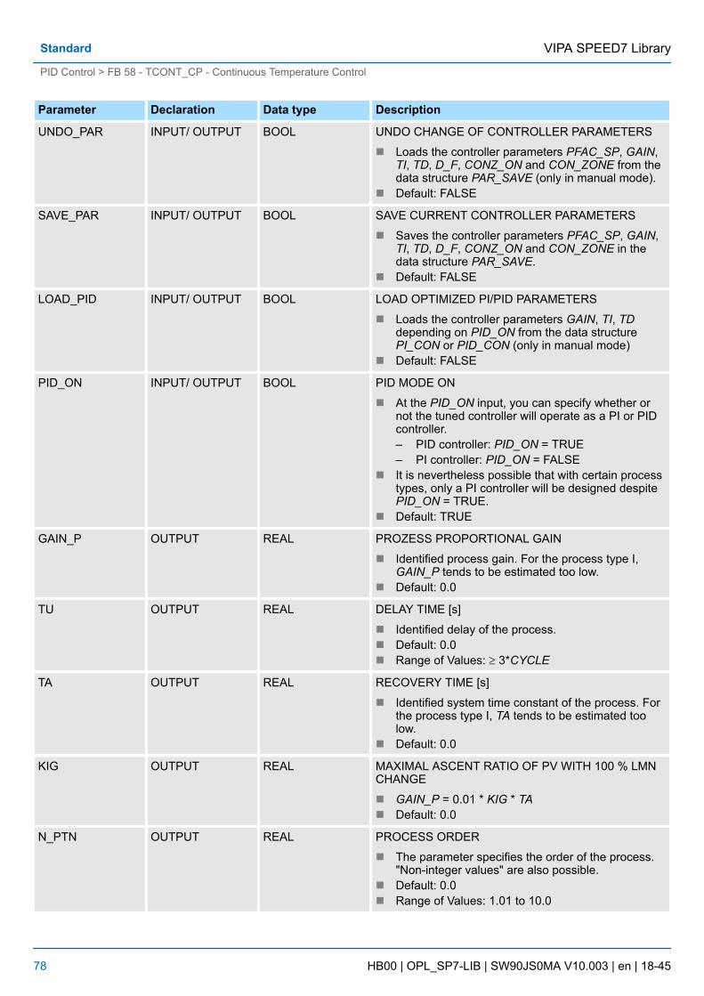
Parameter Declaration Data type Description
UNDO_PAR INPUT/ OUTPUT BOOL UNDO CHANGE OF CONTROLLER PARAMETERS
n Loads the controller parameters PFAC_SP, GAIN,TI, TD, D_F, CONZ_ON and CON_ZONE from thedata structure PAR_SAVE (only in manual mode).
n Default: FALSE
SAVE_PAR INPUT/ OUTPUT BOOL SAVE CURRENT CONTROLLER PARAMETERS
n Saves the controller parameters PFAC_SP, GAIN,TI, TD, D_F, CONZ_ON and CON_ZONE in thedata structure PAR_SAVE.
n Default: FALSE
LOAD_PID INPUT/ OUTPUT BOOL LOAD OPTIMIZED PI/PID PARAMETERS
n Loads the controller parameters GAIN, TI, TDdepending on PID_ON from the data structurePI_CON or PID_CON (only in manual mode)
n Default: FALSE
PID_ON INPUT/ OUTPUT BOOL PID MODE ON
n At the PID_ON input, you can specify whether ornot the tuned controller will operate as a PI or PIDcontroller.– PID controller: PID_ON = TRUE– PI controller: PID_ON = FALSE
n It is nevertheless possible that with certain processtypes, only a PI controller will be designed despitePID_ON = TRUE.
n Default: TRUE
GAIN_P OUTPUT REAL PROZESS PROPORTIONAL GAIN
n Identified process gain. For the process type I,GAIN_P tends to be estimated too low.
n Default: 0.0
TU OUTPUT REAL DELAY TIME [s]
n Identified delay of the process.n Default: 0.0n Range of Values: ³ 3*CYCLE
TA OUTPUT REAL RECOVERY TIME [s]
n Identified system time constant of the process. Forthe process type I, TA tends to be estimated toolow.
n Default: 0.0
KIG OUTPUT REAL MAXIMAL ASCENT RATIO OF PV WITH 100 % LMNCHANGE
n GAIN_P = 0.01 * KIG * TAn Default: 0.0
N_PTN OUTPUT REAL PROCESS ORDER
n The parameter specifies the order of the process."Non-integer values" are also possible.
n Default: 0.0n Range of Values: 1.01 to 10.0
VIPA SPEED7 LibraryStandard
PID Control > FB 58 - TCONT_CP - Continuous Temperature Control
HB00 | OPL_SP7-LIB | SW90JS0MA V10.003 | en | 18-45 78

Parameter Declaration Data type Description
TM_LAG_P OUTPUT REAL TIME LAG OF PTN MODEL [s]
n Time lag of PTN model (values only for N_PTN ³2).
n Default: 0.0
T_P_INF OUTPUT REAL TIME TO POINT OF INFLECTION [s]
n Time from process excitation until the point ofinflection.
n Default: 0.0
P_INF OUTPUT REAL PV AT POINT OF INFLECTION - PV0
n Process variable change from process excitationuntil the point of inflection.
n Default: 0.0n Range of Values: Value range of the process value
LMN0 OUTPUT REAL MANIPULATED VAR. AT BEGIN OF TUNING
n Detected in phase 1 (mean value).n Default: 0.0n Range of Values: 0 ... 100 %
PV0 OUTPUT REAL PROCESS VALUE AT BEGIN OF TUNING
n Default: 0.0n Range of Values: Value range of the process value
PVDT0 OUTPUT REAL RATE OF CHANGE OF PV AT BEGIN OF TUNING[1/s]
n Sign adaptedn Default: 0.0
PVDT OUTPUT REAL CURRENT RATE OF CHANGE OF PV [1/s]
n Sign adaptedn Default: 0.0
PVDT_MAX OUTPUT REAL MAX. RATE OF CHANGE OF PV PER SECOND [1/s]
n Maximum rate of change of the process variable atthe point of inflection at the (sign adapted, always >0), used to calculate TU and KIG.
n Default: 0.0
NOI_PVDT OUTPUT REAL RATIO OF NOISE IN PVDT_MAX IN %
n The higher the proportion of noise, less accurate(less aggressive) the control parameters.
n Default: 0.0
NOISE_PV OUTPUT REAL ABSOLUTE NOISE IN PV
n Difference between maximum and minimumprocess variable in phase 1.
n Default: 0.0
VIPA SPEED7 Library Standard
PID Control > FB 58 - TCONT_CP - Continuous Temperature Control
HB00 | OPL_SP7-LIB | SW90JS0MA V10.003 | en | 18-45 79

Parameter Declaration Data type Description
FIL_CYC OUTPUT INT NO OF CYCLES FOR MEAN-VALUE FILTER
n The process variable is averaged over FIL_CYCcycles. When necessary, FIL_CYC is increasedautomatically from 1 to a maximum of 1024.
n Default: 1n Range of Values: 1 ... 1024
POI_CMAX OUTPUT INT MAX NO OF CYCLES AFTER POINT OF INFLEC-TION
n This time is used to find a further (in other wordsbetter) point of inflection when measurement noiseis present. The tuning is completed only after thistime.
n Default: 2
POI_CYCL OUTPUT INT NUMBER OF CYCLES AFTER POINT OF INFLEC-TION
n Default: 0
n The functionality is based on the PID control algorithm with additional functions fortemperature processes. The controller supplies analog manipulated values and pulse-duration modulated actuating signals. The controller outputs signals to one actuator;in other words, with one controller, you can either heat or cool but not both.
n FB 58 TCONT_CP can be used either purely for heating or purely for cooling. If youuse the block for cooling, GAIN must be assigned a negative value. This inversion ofthe controller means that, for example if the temperature rises, the manipulated vari-able LMN and with it the cooling effort is increased.
n Apart from the functions in the setpoint and process value branches, the FB imple-ments a complete PID temperature controller with a continuous and binary manipu-lated variable output. To improve the control response with temperature processes,the block includes a control zone and reduction of the P-action if there is a setpointstep change. The block can set the PI/PID parameters itself using the controllertuning function.
The values in the controller blocks are only calculated correctly if theblock is called at regular intervals. Therefore, you have to call the con-troller blocks in a cyclic interrupt OB (OB 30 ... 38) at regular intervals.The sampling time is predefined on the parameter CYCLE.
The setpoint is entered at input SP_INT in floating-point format as a physical value or per-centage. The setpoint and process value used to form the error must have the same unit.
Depending on PVPER_ON, the process value can be acquired in the peripheral (I/O) orfloating-point format.
PVPER_ON Process Value Input
TRUE The process value is read in via the analog peripheral I/Os (PIWxxx) at input PV_PER.
FALSE The process value is acquired in floating-point format at inputPV_IN.
Application
Setpoint Branch
Process Value Options(PVPER_ON)
VIPA SPEED7 LibraryStandard
PID Control > FB 58 - TCONT_CP - Continuous Temperature Control
HB00 | OPL_SP7-LIB | SW90JS0MA V10.003 | en | 18-45 80

The CRP_IN function converts the peripheral value PV_PER to a floating-point formatdepending on the switch PER_MODE according to the following rules:
PER_MODE Output of CRP_IN Analog Input Type Unit
0 PV_PER * 0.1 Thermoelements; PT100/NI100; standard
°C; °F
1 PV_PER * 0.01 PT100/NI100; climate °C; °F
2 PV_PER * 100/27648 Voltage/current %
The PV_NORM function calculates the output of CRP_IN according to the following rule:Output of PV_NORM = Ausgang von CPR_IN * PV_FAC + PV_OFFS
It can be used for the following purposes:
n Process value correction with PV_FAC as the process value factor and PV_OFFS asthe process value offset.
n Normalization of temperature to percentageYou want to enter the setpoint as a percentage and must now convert the measuredtemperature value to a percentage.
n Normalization of percentage to temperatureYou want to enter the setpoint in the physical temperature unit and must now convertthe measured voltage/current value to a temperature.
Calculation of the parameters:
n PV_FAC = range of PV_NORM/range of CRP_INn PV_OFFS = LL(PV_NORM) - PV_FAC * LL(CRP_IN); where LL is the lower limit
With the default values (PV_FAC = 1.0 and PV_OFFS = 0.0), normalization is disabled.The effective process value is output at the PV output.
With pulse control, the process value must be transferred to the block inthe fast pulse call (reason: mean value filtering). Otherwise, the controlquality can deteriorate.
If you want to enter the setpoint as a percentage, and you have a temperature range of-20 ... 85 °C applied to CRP_IN, you must normalize the temperature range as a per-centage. The schematic below shows an example of adapting the temperature range-20 ... 85 °C to an internal scale of 0 ... 100 %:
Process Value FormatConversion CRP_IN(PER_MODE)
Process Value Normaliza-tion PV_NORM (PV_FAC,PV_OFFS)
Example of Process Vari-able Normalization
VIPA SPEED7 Library Standard
PID Control > FB 58 - TCONT_CP - Continuous Temperature Control
HB00 | OPL_SP7-LIB | SW90JS0MA V10.003 | en | 18-45 81

The difference between the setpoint and process value is the error before the deadband.The setpoint and process value must exist in the same unit.
To suppress a small constant oscillation due to the manipulated variable quantization (forexample in pulse duration modulation with PULSEGEN) a deadband (DEADBAND) isapplied to the error. If DEADB_W = 0.0, the deadband is deactivated. The effective erroris indicated by the ER parameter.
The schematic below is the block diagram of the PID algorithm:
Forming the Error
Deadband (DEADB_W)
PID Algorithm
VIPA SPEED7 LibraryStandard
PID Control > FB 58 - TCONT_CP - Continuous Temperature Control
HB00 | OPL_SP7-LIB | SW90JS0MA V10.003 | en | 18-45 82

n The PID algorithm operates as a position algorithm. The proportional, integral (INT),and derivative (DIF) actions are connected in parallel and can be activated or deacti-vated individually. This allows P, PI, PD, and PID controllers to be configured.
n The controller tuning supports PI and PID controllers. Controller inversion is imple-mented using a negative GAIN (cooling controller).
n If you set TI and TD to 0.0, you obtain a pure P controller at the operating point.
LMN_Sum(t) manipulated variable in automatic mode of the controllerER (0) step change of the normalized errorGAIN controller gainTI integral timeTD derivative timeD_F derivative factor
In the manual mode, it is corrected as follows: LMN_I = LMN - LMN_P - DISV
PID Algorithm (GAIN, TI,TD, D_F)
Integrator (TI, I_ITL_ON,I_ITLVAL)
VIPA SPEED7 Library Standard
PID Control > FB 58 - TCONT_CP - Continuous Temperature Control
HB00 | OPL_SP7-LIB | SW90JS0MA V10.003 | en | 18-45 83

If the manipulated variable is limited, the I-action is stopped. If the error moves the I-action back in the direction of the manipulated variable range, the I-action is enabledagain.
The I-action is also modified by the following measures:
n The I-action of the controller is deactivated by TI = 0.0n Weakening the P-action when setpoint changes occurn Control zonen The limits of the manipulated variable can be changed online
To prevent overshoot, you can weaken the P-action using the "proportional factor for set-point changes" parameter (PFAC_SP). Using PFAC_SP, you can select continuouslybetween 0.0 and 1.0 to decide the effect of the P-action when the setpoint changes:
n PFAC_SP = 1.0: P-action has full effect if the setpoint changesn PFAC_SP = 0.0: P-action has no effect if the setpoint changes
The weakening of the P-action is achieved by compensating the I-action.
n The D-action of the controller is deactivated with TD = 0.0.n If the D-action is active, the following relationship should apply: TD = 0.5 * CYCLE *
D_F
In the user interface, deactivate the I-action (TI = 0.0) and possible also the D-action (TD= 0.0). Then make the following parameter settings:
n I_ITL_ON = TRUEn I_ITLVAL = operating point;
A feedforward variable can be added at the DISV input.
The schematic below is the block diagram of the manipulated variable calculation:
If CONZ_ON = TRUE, the controller operates with a control zone. This means that thecontroller operates according to the following algorithm:
n If PV exceeds SP_INT by more than CON_ZONE, the value LMN_LLM is output asthe manipulated variable (controlled closed-loop).
n If PV falls below SP_INT by more than CON_ZONE, the value LMN_HLM is output asthe manipulated variable (controlled closed-loop).
n If PV is within the control zone (CON_ZONE), the manipulated variable takes its valuefrom the PID algorithm LMN_Sum (automatic closed-loop control).
Weakening the P-Actionwhen Setpoint ChangesOccur (PFAC_SP)
Derivative Action Element(TD, D_F)
Parameter Settings of a Por PD Controller withOperating Point
Feedforward Control(DISV)
Calculating the Manipu-lated Variable
Control Zone (CONZ_ON,CON_ZONE)
VIPA SPEED7 LibraryStandard
PID Control > FB 58 - TCONT_CP - Continuous Temperature Control
HB00 | OPL_SP7-LIB | SW90JS0MA V10.003 | en | 18-45 84

The changeover from controlled closed-loop to automatic closed-loopcontrol takes into account a hysteresis of 20% of the control zone.
Before activating the control zone manually, make sure that the controlzone band is not too narrow. If the control zone band is too small, oscilla-tions will occur in the manipulated variable and process variable.
When the process value enters the control zone, the D-action causes an extremely fastreduction of the manipulated variable. This means that the control zone is only usefulwhen the D-action is activated. Without a control zone, basically only the reducing P-action would reduce the manipulated variable. The control zone leads to faster settlingwithout overshoot or undershoot if the output minimum or maximum manipulated variableis a long way from the manipulated variable required for the new operating point.
You can switch over between manual and automatic operation. In the manual mode, themanipulated variable is corrected to a manual value. The integral action (INT) is set inter-nally to LMN - LMN_P - DISV and the derivative action (DIF) is set to 0 and synchronizedinternally. Switching over to automatic mode is therefore bumpless.
During tuning, the MAN_ON parameter has no effect.
The value of the manipulated variable is limited to the LMN_HLM and LMN_LLM limits bythe LMNLIMIT function. If these limits are reached, this is indicated by the message bitsQLMN_HLM and QLMN_LLM. If the manipulated variable is limited, the I-action isstopped. If the error moves the I-action back in the direction of the manipulated variablerange, the I-action is enabled again.
Advantage of the ControlZone
Manual Value Processing(MAN_ON, MAN)
Manipulated Variable Limi-tation LMNLIMIT(LMN_HLM, LMN_LLM)
VIPA SPEED7 Library Standard
PID Control > FB 58 - TCONT_CP - Continuous Temperature Control
HB00 | OPL_SP7-LIB | SW90JS0MA V10.003 | en | 18-45 85

If the range of the manipulated variable is reduced and the new unlimited value of themanipulated variable is outside the limits, the I-action and therefore the value of themanipulated variable shifts. The manipulated variable is reduced by the same amount asthe manipulated variable limit changed. If the manipulated variable was unlimited prior tothe change, it is set exactly to the new limit (described here for the upper manipulatedvariable limit).
n The LMN_NORM function normalizes the manipulated variable according to the fol-lowing formula:LMN = LmnN * LMN_FAC + LMN_OFFS
n It can be used for the following purposes:Manipulated variable adaptation with LMN_FAC as manipulated variable factor andLMN_OFFS manipulated variable offset
n The value of the manipulated variable is also available in the peripheral format. TheCRP_OUT function converts the LMN floating-point value to a peripheral valueaccording to the following formula:LMN_PER = LMN * 27648/100With the default values (LMN_FAC = 1.0 and LMN_OFFS = 0.0), normalization is dis-abled. The effective manipulated variable is output at output LMN.
The schematic below shows the block diagram:
If the current parameter settings are usable, you can save them in a special structure inthe instance DB of FB 58 TCONT_CP prior to making a manual change. If you tune thecontroller, the saved parameters are overwritten by the values that were valid prior totuning. PFAC_SP, GAIN, TI, TD, D_F, CONZ_ON and CON_ZONE are written to thePAR_SAVE structure.
The last controller parameter settings you saved can be activated for the controller againusing this function (in manual mode only).
Following tuning, the PI and PID parameters are stored in the PI_CON and PID_CONstructures. Depending on PID_ON, you can use LOAD_PID in the manual mode to writethe PI or PID parameters to the effective controller parameters.
PID parameter PID_ON = TRUE PI parameter PID_ON = FALSE
GAIN = PID_CON.GAIN GAIN = PI_CON.GAIN
TI = PID_CON.TI TI = PI_CON.TI
TD = PID_CON.TD
Changing the ManipulatedVariable Limits Online
Manipulated Variable Nor-malization LMN_NORM(LMN_FAC, LMN_OFFS)
Saving and ReloadingController Parameters
Saving Controller Parame-ters SAVE_PAR
Reloading Saved Con-troller ParametersUNDO_PAR
Changing Between PI andPID Parameters LOAD_PID(PID_ON)
VIPA SPEED7 LibraryStandard
PID Control > FB 58 - TCONT_CP - Continuous Temperature Control
HB00 | OPL_SP7-LIB | SW90JS0MA V10.003 | en | 18-45 86

– The controller parameters are only written back to the controller withUNDO_PAR or LOAD_PID when the controller gain is not 0:For LOAD_PID, the parameters are only copied if the respectiveGAIN <> 0 (either from the PI or PID parameter set). This takes intoaccount the case that no optimization has yet been performed or PIDparameters are missing. If PID_ON = TRUE and PID.GAIN = FALSE,PID_ON is set to FALSE and the PI parameters are copied.
– D_F, PFAC_SP are set to default values by the tuning. These canthen be modified by the user. LOAD_PID does not change theseparameters.
– With LOAD_PID, the control zone is always recalculated(CON_ZONE = 250/GAIN) even when CONZ_ON = FALSE is set.
4.5.5 FB 59 - TCONT_S - Temperature Step ControlFB 59 TCONT_S is used to control technical temperature processes with binary controlleroutput signals for integrating actuators. By setting parameters, subfunctions of the PI stepcontroller can be activated or deactivated and the controller adapted to the process.
Parameters
Parameter Declaration Data type Description
CYCLE INPUT REAL SAMPLE TIME OF STEP CONTROLLER [s]
n At this input CYCLE, you enter the sampling timefor the controller.
n Default: 0.0n Range of Values: ³ 0.001
SP_INT INPUT REAL INTERNAL SETPOINT
n The SP_INT input is used to specify a setpoint.n Default: 0.0n Range of Values: Dependent on the sensors used
PV_IN INPUT REAL PROCESS VARIABLE IN
n An initialization value can be set at the PV_PERinput or an external process variable in floating-point format can be connected.
n Default: 0.0n Range of Values: Dependent on the sensors used
PV_PER INPUT WORD PROCESS VARIABLE PERIPHERY
n The process variable in the peripheral I/O format isconnected to the controller at the PV_PER input.
n Default: 0
DISV INPUT REAL DISTURBANCE VARIABLE
n For feed forward control, the disturbance variable isconnected to the DISV input.
n Default: 0.0
Description
VIPA SPEED7 Library Standard
PID Control > FB 59 - TCONT_S - Temperature Step Control
HB00 | OPL_SP7-LIB | SW90JS0MA V10.003 | en | 18-45 87

Parameter Declaration Data type Description
LMNR_HS INPUT BOOL HIGH LIMIT SIGNAL OF REPEATED MANIPULATEDVALUE
n The signal "valve at upper limit stop" is connectedto the LMNR_HS.
n LMNR_HS = TRUE: The valve is at the upper limitstop.
n Default: FALSE
LMNR_LS INPUT BOOL LOW LIMIT SIGNAL OF REPEATED MANIPULATEDVALUE
n The signal "valve at upper lower stop" is connectedto the input LMNR_LS.
n LMNR_LS = TRUE: The valve is at the lower limitstop.
n Default: FALSE
LMNS_ON INPUT BOOL MANIPULATED SIGNALS ON
n The processing of the controller output signal is setto manual at the LMNS_ON input.
n Default: TRUE
LMNUP INPUT BOOL MANIPULATED SIGNALS UP
n With the controller output signals set to manual, theQLMNUP output signal is applied to the LMNUPinput.
n Default: FALSE
LMNDN INPUT BOOL MANIPULATED SIGNALS DOWN
n With the controller output signals set to manual, theQLMNDN output signal is applied to the LMNDNinput.
n Default: FALSE
QLMNUP OUTPUT BOOL MANIPULATED SIGNAL UP
n If the QLMNUP output is set, the valve will beopened.
n Default: FALSE
QLMNDN OUTPUT BOOL MANIPULATED SIGNAL DOWN
n If the QLMNDN output is set, the valve will beclosed.
n Default: FALSE
PV OUTPUT REAL PROCESS VARIABLE
n The effective process variable is output at the PVoutput.
n Default: 0.0
PE OUTPUT REAL ERROR SIGNAL
n The effective error is output at the PE output.n Default: 0.0
COM_RST INPUT/ OUTPUT BOOL COMPLETE RESTART
n The block has an initialization routine that is pro-cessed when the COM_RST input is set.
n Default: FALSE
VIPA SPEED7 LibraryStandard
PID Control > FB 59 - TCONT_S - Temperature Step Control
HB00 | OPL_SP7-LIB | SW90JS0MA V10.003 | en | 18-45 88

Internal Parameters
Parameter Declaration Data Type Description
PV_FAC INPUT REAL PROCESS VARIABLE FACTOR
n The PV_FAC input is multiplied by the "processvalue". The input is used to adapt the process vari-able range.
n Default: 1.0
PV_OFFS INPUT REAL PROCESS VARIABLE OFFSET
n The PV_OFFS input is added to the process vari-able. The input is used to adapt the process vari-able range.
n Default: 0.0n Range of Values: Dependent on the sensors used
DEADB_W INPUT REAL DEAD BAND WIDTH
n The error passes through a dead band. TheDEADB_W input decides the size of the deadband.
n Default: 0.0n Range of Values: Dependent on the sensors used
PFAC_SP INPUT REAL PROPORTIONAL FACTOR FOR SETPOINTCHANGES [0..1 ]
n PFAC_SP specifies the effective P action whenthere is a setpoint change. This is set between 0and 1.– 1: P action has full effect if the setpoint
changes.– 0: P action has no effect if the setpoint
changes.n Default: 1.0n Range of Values: 0.0 ... 1.0
GAIN INPUT REAL PROPORTIONAL GAIN
n The GAIN input specifies the controller gain. Thedirection of control can be reversed by giving GAINa negative sign.
n Default: 2.0n Range of Values: %/phys. unit
TI INPUT REAL RESET TIME [s]
n The TI input (integral time) decides the integralaction response.
n Default: 40.0 sn Range of Values: ³ 0.0 s
MTR_TM INPUT REAL MOTOR ACTUATING TIME
n The operating time of the valve from limit stop tolimit stop is entered in the MTR_TM parameter.
n Default: 30 sn Range of Values: ³ CYCLE
VIPA SPEED7 Library Standard
PID Control > FB 59 - TCONT_S - Temperature Step Control
HB00 | OPL_SP7-LIB | SW90JS0MA V10.003 | en | 18-45 89

Parameter Declaration Data Type Description
PULSE_TM INPUT REAL MINIMUM PULSE TIME
n A minimum pulse time can be set with thePULSE_TM parameter.
n Default: 0.1sn Range of Values: ³ 0.0 s
BREAK_TM INPUT REAL MINIMUM BREAK TIME
n A minimum break time can be set with theBREAK_TM parameter.
n 0.1sn Range of Values: ³ 0.0 s
PER_MODE INPUT INT PERIPHERIE MODE
n You can enter the type of the I/O module at thisswitch. The process variable at input PV_PER isthen normalized to °C at the PV output.– PER_MODE = 0: standard– PER_MODE = 1: climate– PER_MODE = 2: current/voltage
n Default: 0n Range of Values: 0, 1, 2
PVPER_ON INPUT BOOL PROCESS VARIABLE PERIPHERY ON
n If you want the process variable to be read in fromthe I/O, the PV_PER input must be connected tothe I/O and the PVPER_ON input must be set.
n Default: FALSE
n The functionality is based on the PI control algorithm of the sampling controller. Thisis supplemented by the functions for generating the binary output signal from theanalog actuating signal.
n You can also use the controller in a cascade control as a secondary position con-troller. You specify the actuator position via the setpoint input SP_INT. In this case,you must set the process value input and the parameter TI (integral time) to zero. Anapplication might be, for example, temperature control with heating power controlusing pulse-break activation and cooling control using a butterfly valve. To close thevalve completely, the manipulated variable (ER * GAIN) should be negative.
n Apart from the functions in the process variable branch, FB 59 TCONT_S implementsa complete PI controller with binary manipulated value output and the option of influ-encing the controller output signals manually. The step controller operates without aposition feedback signal.
The values in the controller blocks are only calculated correctly if theblock is called at regular intervals. Therefore, you have to call the con-troller blocks in a cyclic interrupt OB (OB 30 ... 38) at regular intervals.The sampling time is predefined on the parameter CYCLE.
Block Diagram
Application
Forming the Error
VIPA SPEED7 LibraryStandard
PID Control > FB 59 - TCONT_S - Temperature Step Control
HB00 | OPL_SP7-LIB | SW90JS0MA V10.003 | en | 18-45 90

The setpoint is entered at input SP_INT in floating-point format as a physical value or per-centage. The setpoint and process value used to form the error must have the same unit.
Depending on PVPER_ON, the process value can be acquired in the peripheral (I/O) orfloating-point format.
PVPER_ON Process Value Input
TRUE The process value is read in via the analog peripheral I/Os (PIWxxx) at input PV_PER.
FALSE The process value is acquired in floating-point format at inputPV_IN.
The CRP_IN function converts the peripheral value PV_PER to a floating-point formatdepending on the switch PER_MODE according to the following rules:
PER_MODE Output of CRP_IN Analog Input Type Unit
0 PV_PER * 0.1 Thermoelements; PT100/NI100; standard
°C; °F
1 PV_PER * 0.01 PT100/NI100; climate °C; °F
2 PV_PER * 100/27648 Voltage/current %
The PV_NORM function calculates the output of CRP_IN according to the following rule:
Output of PV_NORM = Output of CPR_IN * PV_FAC + PV_OFFS
Setpoint Branch
Process Value Options(PVPER_ON)
Process Value FormatConversion CRP_IN(PER_MODE)
Process Value Normaliza-tion PV_NORM (PF_FAC,PV_OFFS)
VIPA SPEED7 Library Standard
PID Control > FB 59 - TCONT_S - Temperature Step Control
HB00 | OPL_SP7-LIB | SW90JS0MA V10.003 | en | 18-45 91
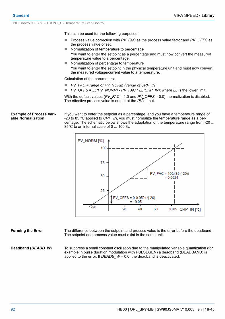
This can be used for the following purposes:
n Process value correction with PV_FAC as the process value factor and PV_OFFS asthe process value offset.
n Normalization of temperature to percentageYou want to enter the setpoint as a percentage and must now convert the measuredtemperature value to a percentage.
n Normalization of percentage to temperatureYou want to enter the setpoint in the physical temperature unit and must now convertthe measured voltage/current value to a temperature.
Calculation of the parameters:
n PV_FAC = range of PV_NORM / range of CRP_INn PV_OFFS = LL(PV_NORM) - PV_FAC * LL(CRP_IN); where LL is the lower limit
With the default values (PV_FAC = 1.0 and PV_OFFS = 0.0), normalization is disabled.The effective process value is output at the PV output.
If you want to enter the setpoint as a percentage, and you have a temperature range of-20 to 85 °C applied to CRP_IN, you must normalize the temperature range as a per-centage. The schematic below shows the adaptation of the temperature range from -20 ...85°C to an internal scale of 0 ... 100 %:
The difference between the setpoint and process value is the error before the deadband.The setpoint and process value must exist in the same unit.
To suppress a small constant oscillation due to the manipulated variable quantization (forexample in pulse duration modulation with PULSEGEN) a deadband (DEADBAND) isapplied to the error. If DEADB_W = 0.0, the deadband is deactivated.
Example of Process Vari-able Normalization
Forming the Error
Deadband (DEADB_W)
VIPA SPEED7 LibraryStandard
PID Control > FB 59 - TCONT_S - Temperature Step Control
HB00 | OPL_SP7-LIB | SW90JS0MA V10.003 | en | 18-45 92

FB 59 TCONT_S works without a position feedback signal (see following block diagram).The I-action of the PI algorithm and the assumed position feedback signal are calculatedin an integrator (INT) and compared as a feedback value with the remaining P-action.The difference is applied to a three-step element (THREE_ST) and a pulse generator(PULSEOUT) that forms the pulses for the valve. Adapting the response threshold of thethree-step element reduces the switching frequency of the controller.
To prevent overshoot, you can weaken the P-action using the "proportional factor for set-point changes" parameter (PFAC_SP). Using PFAC_SP, you can now select continuouslybetween 0.0 and 1.0 to decide the effect of the P-action when the setpoint changes:
n PFAC_SP = 1.0: P-action has full effect if the setpoint changesn PFAC_SP = 0.0: P-action has no effect if the setpoint changes
A value for PFAC_SP < 1.0 can reduce the overshoot as with the continuous controller ifthe motor run time MTR_TM is small compared with the recovery time TA and the ratioTU/TA is < 0.2. If MTR_TM reaches 20 % of TA, only a slight improvement can be ach-ieved.
A load can be added at the DISV input.
With LMNS_ON, you can change between manual and automatic mode. In manualmode, the actuator and the integrator (INT) are set to 0 internally. Using LMNUP andLMNDN, the actuator can be adjusted to OPEN and CLOSED. Switching over to auto-matic mode therefore involves a bump. As a result of the GAIN, the existing error leads toa step change in the internal manipulated variable. The integral component of theactuator, however, results in a ramp-shaped excitation of the process.
PI Step Controller Algo-rithm
Weakening the P-Actionwhen Setpoint ChangesOccur
Feedforward Control
Manual Value Processing(LMNS_ON)
VIPA SPEED7 Library Standard
PID Control > FB 59 - TCONT_S - Temperature Step Control
HB00 | OPL_SP7-LIB | SW90JS0MA V10.003 | en | 18-45 93

4.6 Time Functions4.6.1 UDT 60 - WS_RULES - Rule DB
Your system must provide certain information in a DB that is evaluated by the variousblocks. You create this data block as a DB of the type UDT60 and enter the values thatapply to your location (in local time!).
Calculation of base time < - > local time and "set alarm acc. to local time"
Name Type Start value Comment
B2L STRUCT Base time < - > Local time
S INT 2 Offset base time -> local time [30 min] in winter
permitted: -24 .. +24.
T INT 3 Difference summer to winter time [30 min]
permitted: 2
Block Diagram
Description
VIPA SPEED7 LibraryStandard
Time Functions > UDT 60 - WS_RULES - Rule DB
HB00 | OPL_SP7-LIB | SW90JS0MA V10.003 | en | 18-45 94

Rule for: standard -> daylight-saving time. Default: Last Sunday in March; 2:00 o'clock
Name Type Start value Comment
W2S STRUCT W2S must be specified in STANDARD TIME!
M BYTE B#16#3 Month of switchover
W BYTE B#16#9 nth occurrence of the weekday
(1 = first, 2 = second,. , 9 = last)
D BYTE B#16#1 Day of week (Sunday = 1)
H BYTE B#16#2 Hour
Rule for: daylight-saving -> standard time. Default: Last Sunday in October 3:00 o'clock
Name Type Start value Comment
S2W STRUCT S2W must be specified in DAYLIGHT-SAVING TIME
M BYTE B#16#10 Month of switchover
W BYTE B#16#9 nth occurrence of the weekday
(1 = first, 2 = second,. , 9 = last)
D BYTE B#16#1 Day of week (Sunday = 1)
H BYTE B#16#3 Hour
All the parameters that have the format BYTE are interpreted as BCDvalues!
The specification of the daylight-saving/standard time switchover pointsby a rule is mandatory in the EU as of 2002.
4.6.2 FC 61 - BT_LT - Convert base timer to local timeThe FC 61 calculates the local time for the base time specified at the input.
Parameter
Parameter Declaration Data type Description
BT INPUT DATE_AND_TIME Base time
WS_DAT INPUT BLOCK_DB Information on the time zone for standard/daylightsaving switchover (Rule DB)
RET_VAL OUTPUT INT Error code
LT OUTPUT DATE_AND_TIME Local time
Description
VIPA SPEED7 Library Standard
Time Functions > FC 61 - BT_LT - Convert base timer to local time
HB00 | OPL_SP7-LIB | SW90JS0MA V10.003 | en | 18-45 95

The base time entered at input BT is converted to the local time using the data stored in aDB and applied to output LT. The DB contains the number of 30-minute units by whichthe base time and local time differ and the difference between daylight-saving time andstandard time also in units of 30 minutes. (Rule DB) If the calculation results in a dateoverflow, this is indicated by a special return value.
FC 61 BT_LT can be called in any priority class.
Internally, FC 61 uses the following functions. These functions must be loaded in yourproject with the numbers shown here. FC1 (AD_DT_TM), FC7 (DT_DAY), FC35(SB_DT_TM)
RET_VAL LT Description
0 Local time Block executed error-free
1 Local time No error, but date jump
8082 DT#90-01-01-0:0:0 Invalid data in the rule datablock
4.6.3 FC 62 - LT_BT - Convert local time to base timeThe FC 62 calculates the base time for the local time specified at the input.
Parameters
Parameter Deklaration Datentyp Beschreibung
LT INPUT DATE_AND_TIME Local time
WS_DAT INPUT BLOCK_DB Information on the time zone for standard/daylightsaving switchover (Rule DB)
RET_VAL OUTPUT INT Error code
LT OUTPUT DATE_AND_TIME Base time
The local time entered at input LT is converted to the base time using the data stored in aDB and applied to output BT. The DB contains the number of 30-minute units by whichthe base time and local time differ and the difference between daylight-saving time andstandard time also in units of 30 minutes. (Rule DB) If the calculation results in a dateoverflow, this is indicated by a special return value.
During the switchover from standard to daylight-saving time the local time is put forwardone hour. This, however, means that the hour in between is not run through. If there is anLT (local time) within this hour, FC62 LT_BT "thinks" in daylight-saving time. This isreported with return value 4 or 5.
How It Works
Calling OBs
Call Environment
Output Values / Errors
Description
How It Works
"Forbidden Hour"
VIPA SPEED7 LibraryStandard
Time Functions > FC 62 - LT_BT - Convert local time to base time
HB00 | OPL_SP7-LIB | SW90JS0MA V10.003 | en | 18-45 96

During the switchover from daylight-saving to standard time the local time is put back onehour. This, however, means that one hour is run through twice. (For CE(S)T the designa-tors 2A and 2B apply). For an LT (local time) within this hour, no unique identification rela-tive to a base time is possible. FC LT_BT receives an LT as an input parameter and mustdecide whether the time is standard or daylight-saving before converting it to BT. If the LTis within the double hour, the LT is interpreted as standard time. This is reported withreturn value 2 or 3.
FC 62 LT_BT can be called in any priority class.
Internally, FC 62 uses the following functions. These functions must be loaded in yourproject with the numbers shown here. FC1 (AD_DT_TM), FC7 (DT_DAY), FC35(SB_DT_TM)
RET_VAL LT Description
0 Base time Block executed error-free
1 Base time No error, but date jump
2 Base time The LT at the input is withinthe "double" hour
3 Base time As 2, also date jump
4 Base time The LT at the input is withinthe "forbidden" hour
5 Base time As 4, also date jump
8082 DT#90-01-01-0:0:0 Invalid data in the rule datablock
4.6.4 FC 63 - S_LTINT - Set time interrupt in local timeThe FC sets the required time-of-day interrupt at the set time. This time is output in localtime.
Parameters
Parameter Declaration Data type Description
OB_NR INPUT INT No of the OB to be started (permitted 10 – 17)
SDT INPUT BLOCK_DB Start date and time-of-day in local time (see SFC28)
PERIOD INPUT INT Period from start point SDT:
n W#16#0000 = oncen W#16#0201 = every minuten W#16#0401 = every hourn W#16#1001 = dailyn W#16#1201 = weeklyn W#16#1401 = monthlyn W#16#1801 = annuallyn W#16#2001 = at end of month
"Double Hour"
Calling OBs
Call Environment
Output Values / Errors
Description
VIPA SPEED7 Library Standard
Time Functions > FC 63 - S_LTINT - Set time interrupt in local time
HB00 | OPL_SP7-LIB | SW90JS0MA V10.003 | en | 18-45 97

Parameter Declaration Data type Description
WS_DAT INPUT DATE_AND_TIME Information on the time zone for standard/daylightsaving switchover (see above)
RET_VAL OUTPUT INT Error code
The local time entered at input LT is converted to the base time using the rule stored in aDB. The DB contains the number of 30-minute units by which the base time and localtime differ and the difference between daylight-saving time and standard time also in unitsof 30 minutes (see above). The specified time-of-day interrupt OB is assigned parametervalues and activated using the calculated base time. If the calculation results in a dateoverflow, this is indicated by a special return value.
During the switchover from standard to daylight-saving time the local time is put forwardone hour. This, however, means that the hour in between is not run through. If there is anLT (local time) within this hour, FC S_LTINT "thinks" in daylight-saving time. This isreported with return value 4 or 5.
During the switchover from daylight-saving to standard time the local time is put back onehour. This, however, means that one hour run through twice. (For CE(S)T the designators2A and 2B apply). For an LT (local time) within this hour, no unique identification relativeto a base time is possible. FC S_LTINT receives an LT as input parameter and mustdecide whether the time is standard or daylight-saving before converting it to BT. If the LTis within the double hour, the LT is interpreted as standard time. This is reported withreturn value 2 or 3.
FC 63 S_LTINT can be called in any priority class. Internally, FC S_LTINT uses the fol-lowing functions.
Internally, FC 63 S_LTINT uses the following functions. These functions must be loadedin your project with the numbers shown here. FC7 (DT_DAY), FC35 (SB_DT_TM).
RET_VAL Description
0 Block executed error-free
1 No error, but date jump
2 The LT at the input was within the "double" hour
3 As 2, also date jump
4 The LT at the input is within the "forbidden" hour
5 As 4, also date jump
8082 Invalid data in the rule data block
8090 Bad OB_NR parameter
8091 Bad SDT parameter
8092 Bad PERIOD parameter
80A1 The set start time is in the past
How It Works
"Forbidden Hour"
"Double Hour"
Calling OBs
Call Environment
Output Values / Errors
VIPA SPEED7 LibraryStandard
Time Functions > FC 63 - S_LTINT - Set time interrupt in local time
HB00 | OPL_SP7-LIB | SW90JS0MA V10.003 | en | 18-45 98

RET_VAL Description
80A2 OB is not loaded
80A3 OB cannot be started
VIPA SPEED7 Library Standard
Time Functions > FC 63 - S_LTINT - Set time interrupt in local time
HB00 | OPL_SP7-LIB | SW90JS0MA V10.003 | en | 18-45 99