Viola V1 - Toradexdocs.toradex.com/102052-colibri-arm-viola-datasheet.pdf · Viola provides two...
22
Viola V1.0 Preliminary Datasheet
Transcript of Viola V1 - Toradexdocs.toradex.com/102052-colibri-arm-viola-datasheet.pdf · Viola provides two...

Viola V1.0
Preliminary Datasheet

Viola Preliminary Datasheet
Toradex AG l Altsagenstrasse 5 l 6048 Horw l Switzerland l +41 41 500 48 00 l www.toradex.com l [email protected] Page | 2
Revision History
Date Doc. Rev. PCB Version Changes
08-May-14 Rev. 1.0 V1.0 Preliminary Draft
01-Sept-14 Rev. 1.1 V1.0 - Section 1.2.2, Block Diagram: updated fig.1, added notes for RTC and CAN.
- Section 2.2.5, Ethernet Connector (X5): added notes for ETH_TX0_P/N signals.
- Some minor cosmetic corrections.
Viola Preliminary Datasheet
Toradex AG l Altsagenstrasse 5 l 6048 Horw l Switzerland l +41 41 500 48 00 l www.toradex.com l [email protected] Page | 3
Contents
1. Introduction ............................................................................................................. 5
1.1. Reference Documents ................................................................................................................. 5
1.1.1 Colibri Computer Modules ........................................................................................ 5
1.1.2 Synchronous DC/DC Buck Converter ....................................................................... 5
1.1.3 USB, Current-Limiter, Power-Distribution Switches .................................................... 5
1.2. Features ....................................................................................................................................... 5
1.2.1 Overview ................................................................................................................ 5
1.2.2 Block Diagram ........................................................................................................ 6
1.2.3 User Interface ......................................................................................................... 6
1.2.4 Communication ....................................................................................................... 6
1.2.5 Expansion Connector .............................................................................................. 6
1.2.6 Power Supply .......................................................................................................... 7
1.2.7 Quick-Start Instructions............................................................................................ 7
2. Viola Interfaces ....................................................................................................... 8
2.1. Top Side Connectors: Physical Drawing ...................................................................................... 8
2.2. Top Side Connectors: Pin Assignments ...................................................................................... 9
2.2.1 Colibri SODIMM Connector (X1)............................................................................... 9
2.2.2 Barrel Power Supply Connector (X2) ........................................................................ 9
2.2.3 Terminal Block Power Supply Connector (X3) ........................................................... 9
2.2.4 Central Tab Jumper (JP1) ........................................................................................ 9
2.2.5 Ethernet connector (X5) ........................................................................................... 9
2.2.6 USB Host (X6) ...................................................................................................... 10
2.2.7 Expansion Connector (X9) ..................................................................................... 10
2.3. Bottom Side Connectors: Physical Drawing .............................................................................. 12
2.4. Bottom Side Connectors: Pin Assignment ................................................................................. 13
2.4.1 RGB Connector (X7) ............................................................................................. 13
2.4.2 Micro SD Card Holder (X8) .................................................................................... 14
2.4.3 Battery Holder (BAT1) ........................................................................................... 14
2.5. LEDs........................................................................................................................................... 15
3. Functional ............................................................................................................. 16
3.1. Display interfaces ....................................................................................................................... 16
4. Assembly Options ................................................................................................. 17
4.1. Viola Assembly Options - Top .................................................................................................... 17
4.2. Viola Assembly Options - Bottom .............................................................................................. 18
5. Mechanical Data ................................................................................................... 19
5.1. Dimensions ................................................................................................................................ 19

Viola Preliminary Datasheet
Toradex AG l Altsagenstrasse 5 l 6048 Horw l Switzerland l +41 41 500 48 00 l www.toradex.com l [email protected] Page | 4
5.1.1 Viola Dimensions Top ............................................................................................ 19
5.1.2 Viola Dimensions Bottom ....................................................................................... 20
6. Electrical Characteristics ........................................................................................ 21
6.1. Electrical Specifications ............................................................................................................. 21
7. Temperature Range .............................................................................................. 21
7.1. Operating Temperature Range .................................................................................................. 21
8. RoHS Compliance ................................................................................................. 21

Viola Preliminary Datasheet
Toradex AG l Altsagenstrasse 5 l 6048 Horw l Switzerland l +41 41 500 48 00 l www.toradex.com l [email protected] Page | 5
1. Introduction
Viola is a carrier board that is compatible with the entire family of the Colibri computer-on-modules. It comes with the smallest form factor among the Colibri carrier boards. The optimized price v/s feature trade-off makes it ideal for designing end-products for emerging markets.
1.1. Reference Documents
For detailed technical information about the suitable computer modules, please refer to the sections below:
1.1.1 Colibri Computer Modules
An overview of the Colibri product family:
http://www.toradex.com/products/colibri-arm-modules
1.1.2 Synchronous DC/DC Buck Converter
http://diodes.com/datasheets/AP6502.pdf
1.1.3 USB, Current-Limiter, Power-Distribution Switches
http://www.ti.com/product/tps2042b
1.2. Features
1.2.1 Overview
Viola provides the following features and communication interfaces:
2x USB Host, Type A USB connector
10/100 Mbps Ethernet, RJ45 connector
MicroSD Card connector
Digital RGB interface, Unified EDT display interface
Communication Peripherals: SSP, UART, I2C (on expansion connector)
Digital I/O Interface: 4 PWM channels and 11 GPIOs (on expansion connector)
Analog Input Interface: 4 ADC channels (on expansion connector)
CAN (on expansion connector) (Refer note 1)
External real-time clock with battery backup (For more details, refer to Section 4, Assembly Options).

Viola Preliminary Datasheet
Toradex AG l Altsagenstrasse 5 l 6048 Horw l Switzerland l +41 41 500 48 00 l www.toradex.com l [email protected] Page | 6
1.2.2 Block Diagram
Fig. 1 Viola Block Diagram
* External RTC: Not assembled by default. For more details, refer to Section 4, Assembly Options. * CAN: For more details, refer to note 1.
1.2.3 User Interface
Viola provides a digital RGB interface port (18-bpp) to interface with the LCD panels. EDT Unified display interface is provided on the board which has a built-in 4 wire resistive touch on the same connector. A variety of LCD panels with integrated touch support for evaluation purposes are available at the Toradex Webshop.
For customers looking for capacitive touch display, Viola is fully compatible with Toradex Capacitive Multi-Touch Display solution. Please refer to the following developer page link for more details:
http://developer.toradex.com/product-selector/capacitive-multi-touch-display
LED indication is available to indicate +5V power supply status.
1.2.4 Communication
The commonly used communication functions are fully implemented on the Viola carrier board and include:
1x 10/100 Mbps Ethernet
2x USB 2.0 Host
1x SPI (on expansion connector)
1x I2C (on expansion connector)
3x UART(UART-A, UART-B, and UART-C on expansion connector)
1x CAN (on expansion connector) (Refer note 1)
1.2.5 Expansion Connector
The expansion connector provides 50 pins with different functionalities. Some of these functions might change depending on the Colibri module that is used. The available signals are selected to provide good flexibility in terms of peripherals which can be attached to it.
COLIBRI MODULE
SODIMM CONNECTOR
DC/DC Buck Regulator (step down to 3.3V)
1x Ethernet 10/100Mbps
2x USB Host
LED
Indication Expansion Connector
(Power, I2C, SPI, UART A/B/C, GPIOs, ANALOG IN, PWM,
CAN * )
Power Input (5V+/-0.25V, 3A)
1x EDT Display Connector
External RTC * 1x MicroSD Card

Viola Preliminary Datasheet
Toradex AG l Altsagenstrasse 5 l 6048 Horw l Switzerland l +41 41 500 48 00 l www.toradex.com l [email protected] Page | 7
1.2.6 Power Supply
Viola provides two methods of supplying power to the board, which require 5V +/-0.25V DC input power supply.
The connector X2, which is a standard 5.5 mm power jack barrel connector, is widely used in consumer electronic devices. By default, connector (X2) is not part of the assembly (For more details, refer to Section 4, Assembly Options).
The connector X3, which is a pluggable, terminal block type connector, is widely used in industrial applications.
For more details, please refer to Section 6, Electrical Characteristics
Note: Power supply is not protected against reverse input voltage polarity and overvoltage.
1.2.7 Quick-Start Instructions
Perform the following steps to quick-start the Viola carrier board:
1. Insert a Colibri module into the SODIMM socket X1 on the Viola carrier board.
2. Connect the EDT Unified TFT display to the connector X7. Connect a keyboard and mouse to the USB ports.
3. Connect an external power supply (recommended: 5V +/-0.25V, 3A) to the board by the X2 (or X3) connector.
Note: Power consumption depends on the module/peripheral used.
4. The system starts as soon as the power supply is connected. LED will glow to indicate the presence of the 5V power and the pre-installed operating system boots.
For detailed documentation of the software as well as for the latest bootloader and software images
please refer to the Toradex Developer Website: http://developer.toradex.com
Viola Preliminary Datasheet
Toradex AG l Altsagenstrasse 5 l 6048 Horw l Switzerland l +41 41 500 48 00 l www.toradex.com l [email protected] Page | 8
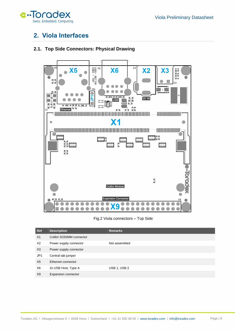
2. Viola Interfaces
2.1. Top Side Connectors: Physical Drawing
Fig.2 Viola connectors – Top Side
Ref Description Remarks
X1 Colibri SODIMM connector
X2 Power supply connector Not assembled
X3 Power supply connector
JP1 Central tab jumper
X5 Ethernet connector
X6 2x USB Host, Type A USB 1, USB 2
X9 Expansion connector

Viola Preliminary Datasheet
Toradex AG l Altsagenstrasse 5 l 6048 Horw l Switzerland l +41 41 500 48 00 l www.toradex.com l [email protected] Page | 9
2.2. Top Side Connectors: Pin Assignments
2.2.1 Colibri SODIMM Connector (X1)
Type: SODIMM 200 Socket Manufacturer: Tyco Electronics-1473005-1 Refer to the Colibri datasheets for the pin-out assignment details of the Colibri modules.
2.2.2 Barrel Power Supply Connector (X2)
Connector type: RAPC722X
Pin Description Voltage / range
1 +5V_PWR_IN 5V, +/- 0.25V
2 GND_IN
Note: By default, connector (X2) is not part of the assembly.
2.2.3 Terminal Block Power Supply Connector (X3)
Connector type: Tyco 284512-2
Pin Description Voltage / range
1 GND_IN
2 +5V_PWR_IN 5V, +/- 0.25V
2.2.4 Central Tab Jumper (JP1)
Jumper JP1 should be configured based upon the Ethernet controller which is present on the installed Colibri module. Header pin pitch: 2.54 mm.
Jumper position Description
1-2 Use this configuration for Colibri PXA270 modules
2-3 Use this configuration for all other modules
2.2.5 Ethernet connector (X5)
Connector type: RJ-45, Pulse J00-0065NL
Pin Signal Name I/O Type Voltage Pull-up/Pull-down
1 ETH_TX0_P * O +3.3V 50R to ETH_AVCC
2 ETH_TX0_N * O +3.3V 50R to ETH_AVCC
3 ETH_RXI_P I +3.3V
4 ETH_AVCC (ETH_CT_TX) PWR
5 ETH_AGND (ETH_CT_RX) PWR
6 ETH_RXI_N I +3.3V
7 NC
8 SHIELD
9 +3.3V PWR
10 ETH_LINK_ACT I +3.3V
11 ETH_LED_ACT I +3.3V
12 +3.3V PWR
S1 SHIELD
S2 SHIELD
* On Viola V1.0 and V1.1, ETH_TX0_P/N signals are swapped with respect to Colibri standard pin-out. The error won’t affect Ethernet operation, since cable diagnostic (polarity detection) and correction are performed by the Ethernet PHY. The error will be fixed in the next hardware revision.

Viola Preliminary Datasheet
Toradex AG l Altsagenstrasse 5 l 6048 Horw l Switzerland l +41 41 500 48 00 l www.toradex.com l [email protected] Page | 10
2.2.6 USB Host (X6)
The USB interface is able to support USB 2.0 high speed and operate at a maximum of 480 Mbit/s, depending upon the Colibri module being used.
Connector type: USB Type-A
Pin Description Voltage
L1 VCC_USB1 +5V
L2 USB_D1_N
L3 USB_D1_P
L4 GND
U1 VCC_USB2 +5V
U2 USB_D2_N
U3 USB_D2_P
U4 GND
S1 SHIELD
S2 SHIELD
S3 SHIELD
S4 SHIELD
2.2.7 Expansion Connector (X9)
Connector type: 2x25 Pin Header Male, 2.54 mm
Pin Signal Name SODIMM Number I/O Type Voltage Pull-up/Pull-down
1 +5V PWR +5V
2 RESET_EXT# 26 I +3.3V
3 RESET_OUT# 87 O +3.3V
4 +3.3V PWR +3.3V
5 I2C_SCL 196 I/O +3.3V 4.7K to 3.3V
6 I2C_SDA 194 I/O +3.3V 4.7K to 3.3V
7 GND PWR
8 PIN_188 (GPIO) 188 I/O +3.3V
9 PIN_186 (GPIO) 186 I/O +3.3V
10 PIN_184 (GPIO) 184 I/O +3.3V
11 PIN_133 (GPIO) 133 I/O +3.3V
12 PIN_127 (GPIO) 127 I/O +3.3V
13 PIN_134 (GPIO) 134 I/O +3.3V
14 PIN_104 (GPIO) 104 I/O +3.3V
15 PIN_102 (GPIO) 102 I/O +3.3V
16 PIN_100 (GPIO) 100 I/O +3.3V
17 PIN_55 (GPIO)
(Refer note 1)
55 I/O +3.3V
18 PIN_63 (GPIO)
(Refer note 1)
63 I/O +3.3V
19 GND PWR
20 SSP_TX 92 O +3.3V
21 SSP_RX 90 I +3.3V
22 SSP_CLK 88 I/O +3.3V
Viola Preliminary Datasheet
Toradex AG l Altsagenstrasse 5 l 6048 Horw l Switzerland l +41 41 500 48 00 l www.toradex.com l [email protected] Page | 11
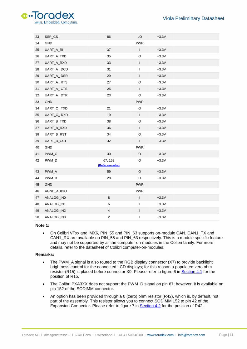
23 SSP_CS 86 I/O +3.3V
24 GND PWR
25 UART_A_RI 37 I +3.3V
26 UART_A_TXD 35 O +3.3V
27 UART_A_RXD 33 I +3.3V
28 UART_A_ DCD 31 I +3.3V
29 UART_A_ DSR 29 I +3.3V
30 UART_A_ RTS 27 O +3.3V
31 UART_A_ CTS 25 I +3.3V
32 UART_A_ DTR 23 O +3.3V
33 GND PWR
34 UART_C_ TXD 21 O +3.3V
35 UART_C_ RXD 19 I +3.3V
36 UART_B_TXD 38 O +3.3V
37 UART_B_RXD 36 I +3.3V
38 UART_B_RST 34 O +3.3V
39 UART_B_CST 32 I +3.3V
40 GND PWR
41 PWM_C 30 O +3.3V
42 PWM_D 67, 152
(Refer remarks)
O +3.3V
43 PWM_A 59 O +3.3V
44 PWM_B 28 O +3.3V
45 GND PWR
46 AGND_AUDIO PWR
47 ANALOG_IN0 8 I +3.3V
48 ANALOG_IN1 6 I +3.3V
49 ANALOG_IN2 4 I +3.3V
50 ANALOG_IN3 2 I +3.3V
Note 1:
On Colibri VFxx and iMX6, PIN_55 and PIN_63 supports on-module CAN. CAN1_TX and CAN1_RX are available on PIN_55 and PIN_63 respectively. This is a module specific feature and may not be supported by all the computer-on-modules in the Colibri family. For more details, refer to the datasheet of Colibri computer-on-modules.
Remarks:
The PWM_A signal is also routed to the RGB display connector (X7) to provide backlight brightness control for the connected LCD displays; for this reason a populated zero ohm resistor (R15) is placed before connector X9. Please refer to figure 6 in Section 4.1 for the position of R15.
The Colibri PXA3XX does not support the PWM_D signal on pin 67; however, it is available on pin 152 of the SODIMM connector.
An option has been provided through a 0 (zero) ohm resistor (R42), which is, by default, not part of the assembly. This resistor allows you to connect SODIMM 152 to pin 42 of the Expansion Connector. Please refer to figure 7 in Section 4.2 for the position of R42.

Viola Preliminary Datasheet
Toradex AG l Altsagenstrasse 5 l 6048 Horw l Switzerland l +41 41 500 48 00 l www.toradex.com l [email protected] Page | 12
2.3. Bottom Side Connectors: Physical Drawing
Fig.3 Viola connectors – Bottom Side
Ref. Description Remarks
X7 RGB connector
X8 Micro SD Card Holder
BAT1 12 mm Battery Holder Not assembled
Supported batteries: BR1216, CR1216, BR1220, CL1220, CR1220, BR1225

Viola Preliminary Datasheet
Toradex AG l Altsagenstrasse 5 l 6048 Horw l Switzerland l +41 41 500 48 00 l www.toradex.com l [email protected] Page | 13
2.4. Bottom Side Connectors: Pin Assignment
2.4.1 RGB Connector (X7)
The RGB (18-bpp) display interface uses the Unified EDT display interface pin-out, for which there are a wide variety of displays of different sizes and resolutions available, which connect directly via a 40 way FFC.
Connector type: Omron XF2M-4015-1A
Pin Signal Name SODIMM Number
I/O Type Voltage Pull-up/Pull-down
1 GND PWR
2 GND PWR
3 +3.3V PWR +3.3V
4 +3.3V PWR +3.3V
5 BL_ON 71 O +3.3V
6 PWM_A 59 O +3.3V
7 LCD_RESET_OUT# 87 O +3.3V
8 LCD_BLUE_5 72 O +3.3V
9 LCD_BLUE_4 78 O +3.3V
10 LCD_BLUE_3 58 O +3.3V
11 LCD_BLUE_2 60 O +3.3V
12 LCD_BLUE_1 70 O +3.3V
13 LCD_BLUE_0 76 O +3.3V
14 GND PWR
15 LCD_GREEN_5 50 O +3.3V
16 LCD_GREEN _4 74 O +3.3V
17 LCD_GREEN _3 48 O +3.3V
18 LCD_GREEN _2 62 O +3.3V
19 LCD_GREEN _1 46 O +3.3V
20 LCD_GREEN _0 80 O +3.3V
21 GND PWR
22 LCD_RED_5 61 O +3.3V
23 LCD_RED_4 57 O +3.3V
24 LCD_RED_3 64 O +3.3V
25 LCD_RED_2 66 O +3.3V
26 LCD_RED_1 54 O +3.3V
27 LCD_RED_0 52 O +3.3V
28 LCD_PCLK_WR 56 O +3.3V
29 GND PWR
30 LCD_LCLK_A0 68 O +3.3V
31 LCD_FCLK_RD 82 O +3.3V
32 LCD_BIAS 44 O +3.3V
33 Connected to 3.3V or GND via assembly option. The default assembly is GND. For more details, refer to Section 4, Assembly Options
O +3.3V
/ GND
34 Connected to 3.3V or GND via assembly option. The default assembly is GND. For more details, refer to Section 4, Assembly Options
O +3.3V
/ GND

Viola Preliminary Datasheet
Toradex AG l Altsagenstrasse 5 l 6048 Horw l Switzerland l +41 41 500 48 00 l www.toradex.com l [email protected] Page | 14
35 GND PWR
36 +3.3V PWR +3.3V
37 TOUCH_TSPY 18 O +3.3V
38 TOUCH_TSMX 16 O +3.3V
39 TOUCH_TSMY 20 O +3.3V
40 TOUCH_TSPX 14 O +3.3V
2.4.2 Micro SD Card Holder (X8)
Connector type: Amphenol 101-00581-59
Pin Signal Name I/O Type Voltage Pull-up/Pull-down
1 MM_DAT_2 I/O +3.3V 68K to +3.3V
2 MM_DAT_3 I/O +3.3V 68K to +3.3V
3 MM_CMD I +3.3V 33K to +3.3V
4 +3.3V PWR +3.3V
5 MM_CLK I +3.3V
6 GND PWR
7 MM_DAT_0 I/O +3.3V 68K to +3.3V
8 MM_DAT_1 I/O +3.3V 68K to +3.3V
CD1/2 MM_CD
S1/2 SHIELD
2.4.3 Battery Holder (BAT1)
Connector type: KEYSTONE-3000
Pin Description Voltage
1 VCC_BAT +3.0V
2 GND
Note: By default, battery holder is not part of the assembly.
Viola Preliminary Datasheet
Toradex AG l Altsagenstrasse 5 l 6048 Horw l Switzerland l +41 41 500 48 00 l www.toradex.com l [email protected] Page | 15
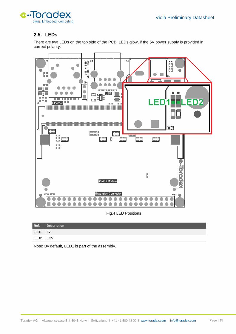
2.5. LEDs
There are two LEDs on the top side of the PCB. LEDs glow, if the 5V power supply is provided in correct polarity.
Fig.4 LED Positions
Ref. Description
LED1 5V
LED2 3.3V
Note: By default, LED1 is part of the assembly.

Viola Preliminary Datasheet
Toradex AG l Altsagenstrasse 5 l 6048 Horw l Switzerland l +41 41 500 48 00 l www.toradex.com l [email protected] Page | 16
3. Functional
3.1. Display interfaces
Viola carrier board facilitates connection of the LCD panel directly to the board using a 40 way FFC. Unified TFT Interface supports18 bit digital RGB configuration as per Unified EDT display standard.
The following image shows the display interface architecture that has been implemented on the Viola carrier board.
Fig.5 Display Interface Architecture
Unified TFT Interface also supports 4-wire resistive touch signals connection via the same 40 way FFC.
Colibri Digital RGB
Interface
Unified EDT Interface
RGB (18 bpp)
4-Wire Resistive Touch

Viola Preliminary Datasheet
Toradex AG l Altsagenstrasse 5 l 6048 Horw l Switzerland l +41 41 500 48 00 l www.toradex.com l [email protected] Page | 17
4. Assembly Options
This section describes the assembly options that can be used to configure different features and functional options. The following table lists all the assembly options that have been described in the previous pages of this document.
Solution Selected Assembly Options Assembled Components
PCB Side
Recovery mode (Only with Colibri Txx) Assemble 10KΩ resistors R49 to enter recovery mode Top
Disable Compact Flash card detect
(Only with Colibri Txx)
R47 assembled R47 Top
Disable PS/2 Driver
(Only with Colibri T20)
R43, R44, R45, R46 assembled R43, R44, R45, R46
Top/Bottom
SD Boot (only with Colibri T20) Assemble 100 Ω resistors R50, R51, R52, R53, R54 Bottom
PWM_D for PXA3XX modules Assemble the resistor R42 Bottom
Battery power internal RTC Disassemble R39 and assemble R38 R39 Bottom
External RTC Assemble components IC4, BAT1, C28, C29, C30, C31, D4, OSC1, R35, R36, R37
Bottom
Unified EDT Display , Rotate display Assemble appropriate 0R resistors R24, R25, R26, and R27. Refer LCD TFT datasheet for configuration details.
R25, R27 Bottom
4.1. Viola Assembly Options - Top
Fig.6 Viola Assembly Options – Top Side

Viola Preliminary Datasheet
Toradex AG l Altsagenstrasse 5 l 6048 Horw l Switzerland l +41 41 500 48 00 l www.toradex.com l [email protected] Page | 18
4.2. Viola Assembly Options - Bottom
Fig.7 Viola Assembly Options – Bottom Side

Viola Preliminary Datasheet
Toradex AG l Altsagenstrasse 5 l 6048 Horw l Switzerland l +41 41 500 48 00 l www.toradex.com l [email protected] Page | 19
5. Mechanical Data
5.1. Dimensions
5.1.1 Viola Dimensions Top
Fig.8 Viola Dimensions – Top Side, all dimensions are in millimetres (mm)

Viola Preliminary Datasheet
Toradex AG l Altsagenstrasse 5 l 6048 Horw l Switzerland l +41 41 500 48 00 l www.toradex.com l [email protected] Page | 20
5.1.2 Viola Dimensions Bottom
Fig.9 Viola Dimensions – Bottom Side, all dimensions are in millimetres (mm)

Viola Preliminary Datasheet
Toradex AG l Altsagenstrasse 5 l 6048 Horw l Switzerland l +41 41 500 48 00 l www.toradex.com l [email protected] Page | 21
6. Electrical Characteristics
6.1. Electrical Specifications
Symbol Description Voltage Min Typ Max Unit
PWR_IN_V Main power supply voltage 4.75 5 5.25 V
PWR_IN_I Main power supply current - 5 A
V_BACKUP Optional RTC battery voltage 2.3 3 3.6 V
I_(+5V) Maximum continuous current at power rail
+5V 2.0 A
I_(+3.3V) Maximum continuous current at power rail +3.3V 2.0 A
I_Pin(X9) Current for single power pin 4 of connector X9 +3.3V 1.0 A
I_Pin(X9) Current for single power pin 1 of connector X9 +5V 1.0 A
I_Pin(X6) Current available for 2X USB Host on connector X6
Maximum current limit on each USB is 500mA
+5V 1.0 A
7. Temperature Range
7.1. Operating Temperature Range
TBD
8. RoHS Compliance
The Viola baseboard complies with the European Union’s Directive 2002/95/EC: "Restrictions of Hazardous Substances".

Viola Preliminary Datasheet
Toradex AG l Altsagenstrasse 5 l 6048 Horw l Switzerland l +41 41 500 48 00 l www.toradex.com l [email protected] Page | 22
Disclaimer:
Copyright © 2014 Toradex AG. All rights reserved. All data is for information purposes only and not guaranteed for legal purposes. Information has been carefully checked and is believed to be accurate; however, no responsibility is assumed for inaccuracies.
Brand and product names are trademarks or registered trademarks of their respective owners.
Specifications are subject to change without notice.

![Vecta Vending Colibri Operating Manual[1]](https://static.fdocuments.in/doc/165x107/552738c0497959f10f8b48d5/vecta-vending-colibri-operating-manual1.jpg)