VIKING RANGE CORPORATION, P. O. BOX 956, … · PROXIMITY TO SIDE CABINET INSTALLATION 1. Range /...
42
VIKING RANGE CORPORATION, P. O. BOX 956, GREENWOOD, MS. 38930
-
Upload
hoangnguyet -
Category
Documents
-
view
213 -
download
0
Transcript of VIKING RANGE CORPORATION, P. O. BOX 956, … · PROXIMITY TO SIDE CABINET INSTALLATION 1. Range /...
VIKING RANGE CORPORATION, P. O. BOX 956, GREENWOOD, MS. 38930

TABLE OF CONTENTS Customer Information----------------------------- 4 Baking Problem Remedies------------------------ 4 Viking Model Numbers--------------------------- 5 Product Warranty----------------------------------- 6 Proximity to Surrounding Cabinets--------------- 8 Range Leveling------------------------------------- 9 Surface Burner Adjustments---------------------- 10 Oven / Grill / Griddle Burner Adjustment------ 11 Direct Spark Ignition (DSI) Module Specs----- 12 Timing Diagram------------------------------------ 14 COMPONENTS:
Door Lock Control / Timer--------------- 15 Door Lock Motor Assembly-------------- 15 Cooling Fan Motor------------------------- 16 Cooling Fan Limit Switch----------------- 16 Convection Fan Motor--------------------- 16 Auto Reset Switch-------------------------- 17 High Limit Switch-------------------------- 17 Direct Spark Ignition Module------------- 18 Oven Thermostat---------------------------- 18 Relay------------------------------------------ 18 Gas Valves----------------------------------- 19 Halogen Light Transformer---------------- 19 Re-Ignition Module------------------------- 19 Spark Ignition Switch----------------------- 19 Selector Switch------------------------------ 20 Oven Indicator Light (Cycle)-------------- 20 Oven Indicator Light (Clean)-------------- 20 Oven Light Switch-------------------------- 20
Component Contacts and Wiring----------------- 21 WIRING DIAGRAMS:
Bake------------------------------------------ 23 Convection Bake--------------------------- 24 Broil----------------------------------------- 25 Convection Broil--------------------------- 26 Clean Before Door Lock------------------ 27 Clean Before 600°F After Door Lock--- 28 Clean After 600°F After Door Lock---- 29
Control Timer (PC Board) Voltage Reading--- 30 Door Removal-------------------------------------- 31 Oven Door Assembly------------------------------ 32 Handle, Logo and Door Hinge Removal-------- 32 Component Location------------------------------- 33 Control Panel Removal---------------------------- 34 Landing Ledge Removal-------------------------- 34 Oven Light Switch Removal---------------------- 34 Indicator Light Voltage Check------------------- 34 Oven Light Switch--------------------------------- 34 Oven Light Removal------------------------------ 34 Top Burner Removal------------------------------ 35 Top Burner Ignitor Removal--------------------- 35 Spark Module Removal--------------------------- 35 Infra-red Burner Removal------------------------ 35 Broil Ignitor Removal----------------------------- 35 Top Burner Valve Replacement------------------ 36 Pressure Regulator Removal---------------------- 36 Oven Burner Removal----------------------------- 36 Convection Fan Removal-------------------------- 36 Indicator Light Removal--------------------------- 37 Bake / Broil Thermostat Removal---------------- 37 Oven Ignitor Electrode Removal----------------- 37 Broil Gas Valve Removal------------------------- 37 Oven Gas Valve Removal------------------------- 37 Access to the Self-Clean Electronic Circuit
for Repair------------------------------------ 38 Component Location------------------------------- 38 Self-Clean Lock Replacement--------------------- 39 “LOCKED” Door------------------------------------ 40 Troubleshooting Guide------------------------------ 41
3

IMPORTANT Information (Note to Customer)
The information contained in this manual is intended for use by a qualified service technician who is familiar with the application of all safety procedures required in the repair of any gas or electric appliance, and who is equipped with the proper tools and testing instruments. Repairs covered in this manual and made by unqualified persons can result in hazards developing due to improper assembly or adjustment. Inexperienced persons making such repairs subject themselves to the risk of injury or electrical shock which can be serious or even fatal. If you perform service on your own Viking product, you must assume responsibility of personal injury or property damage which may result. Viking will not be responsible for injury or property damage arising from service performed by other than Viking Factory Authorized Service Agencies. In order to locate a Viking Factory Authorized Service Agency, please consult the dealer from whom you purchased this product. You may also write to: Viking Preferred Service P.O. Drawer 956 G reenwood, Ms. 38930
BAKING PROBLEM REMEDIES Problem Cause Remedy Food browns unevenly Improper heating Preheat until oven indicator light
goes out. Aluminum foil on rack or oven Remove foil bottom. Baking utensils too large for the Use correct size utensil. recipe or oven. Several utensils crowded together Leave at least 1 1/2" (3.8 cm) or
more space between all utensils and oven walls.
Food too brown on bottom Baking utensil too large Use correct utensil Baking utensil dark or glass Lower oven temperature 25°F
(-3.8°C) for this type of utensil.
Food dries before browning Oven temperature too high Lower oven temperature Oven door open too frequently Check food at minimum time
Cookies too brown on bottom Pans too deep Use a cookie sheet (not a baking pan.
Dark cookie sheet Use light, shiny cookie sheet Oven temperature too high Lower oven temperature
Cookies too flat Hot cookie sheet Allow cookie sheet to cool between batches
Cake too brown on bottom Oven temperature too high Lower temperature; if using or crust forms on bottom glass pan, lower 25°F (-3.8°C) Cakes burns on sides or not Oven too Hot Reduce temperature; done in center Wrong pan size Use recommended pan size; fill
pan no more than 2/3 full.
4

NEW VIKING MODEL NUMBERS
RANGES AND RANGETOPS
V G R C 4 8 5 4 G Q D S S V-Viking Color
AL-Almond G-Gas Bk-Black
BU-Burgundy SS-24" D FG-Forest Green
Standard Range (30"W) GG-Graphite Gray SC-27" D LN- Linen
Convection Range (30"W) PL-Plum Self - Clean SS-Stainless Steel
RC-27" D VB-Viking Blue Convection Range (36"/48"W) WH-White
RT-24" D Rangetop
Width 30" 36" 48" D-Oven Door Window 60"
Q-12" Wide Grill 0-Standard Oven 5-Convection Oven G-Griddle
12" Wide 24" Wide
Number of Surface Burners
5

VIKING RANGE CORPORATION PRODUCT WARRANTY COOKING PRODUCTS
FREE STANDING GAS RANGES
* 90 DAYS-GLASS, PAINTED, PORCELAIN AND DECORATIVE ITEMS
* 1 YEAR FULL WARRANTY-COMPONENTS AND ACCESSORIES
* 5 YEAR LIMITED WARRANTY-SURFACE BURNER, GRIDDLE TUBULAR BURNER, GRILL TUBULAR
BURNER (PART ONLY) * 10 YEAR LIMITED WARRANTY-ANY PORCELAIN
OVEN OR PORCELAIN INNER DOOR WHICH RUSTS THROUGH
DUAL FUEL RANGES
* 90 DAYS-GLASS, PAINTED, PORCELAIN AND DECORATIVE ITEMS
* 1 YEAR FULL WARRANTY-COMPONENTS AND ACCESSORIES
* 5 YEAR LIMITED WARRANTY-SURFACE BURNER, GRIDDLE TUBULAR BURNER, GRILL TUBULAR BURNER, BAKE ELEMENT, BROIL ELEMENT, OR CONVECTION COOK ELEMENT (PART ONLY)
* 10 YEAR LIMITED WARRANTY-ANY PORCELAIN OVEN OR PORCELAIN INNER DOOR PANEL
WHICH RUSTS THROUGH
ELECTRIC RANGES * 90 DAYS-GLASS, PAINTED, PORCELAIN AND
DECORATIVE ITEMS * 1 YEAR FULL WARRANTY-COMPONENTS AND
ACCESSORIES * 5 YEAR-ANY HALOGEN ELEMENT, BAKE
ELEMENT, BROIL ELEMENT, OR CONVECTION COOK ELEMENT (PART ONLY)
* 10 YEAR LIMITED WARRANTY-ANY PORCELAIN OVEN OR PORCELAIN INNER DOOR PANEL
WHICH RUSTS THROUGH GAS RANGETOPS
* 90 DAYS -GLASS, PAINTED, PORCELAIN AND DECORATIVE ITEMS
* 1 YEAR FULL WARRANTY-COMPONENTS AND ACCESSORIES
* 5 YEAR LIMITED WARRANTY-SURFACE BURNERS, GRIDDLE TUBULAR BURNER, GRILL TUBULAR BURNER (PART ONLY) ELECTRIC RANGE TOP
* 90 DAYS-GLASS, PAINTED, PORCELAIN AND DECORATIVE ITEMS
* 1 YEAR FULL WARRANTY-COMPONENTS AND ACCESSORIES
* 5 YEAR-ANY HALOGEN ELEMENT, BAKE ELEMENT, BROIL ELEMENT, OR CONVECTION COOK ELEMENT (PART ONLY)
GAS WALL OVENS
* 90 DAYS-GLASS, PAINTED, PORCELAIN AND DECORATIVE ITEMS
* 1 YEAR FULL WARRANTY-COMPONENTS AND ACCESSORIES
* 5 YEARS-OVEN TUBULAR BURNER (PART ONLY) * 10 YEAR LIMITED WARRANTY-ANY PORCELAIN OVEN OR PORCELAIN INNER DOOR PANEL
WHICH RUSTS THROUGH ELECTRIC WALL OVENS
* 90 DAYS-GLASS, POINTED, PORCELAIN AND DECORATIVE ITEMS
* 1 YEAR FULL WARRANTY-COMPONENTS AND ACCESSORIES
* 5 YEARS LIMITED WARRANTY-OVEN BAKE, BROIL,
OR CONVECTION HEATING ELEMENTS * 10 YEAR LIMITED WARRANTY-ANY PORCELAIN
OR PORCELAIN INNER DOOR PANEL WHICH RUSTS THROUGH WARMING DRAWERS
* 90 DAYS-PAINTED AND DECORATIVE ITEMS * 1 YEAR FULL WARRANTY-COMPONENTS AND
ACCESSORIES * 5 YEAR LIMITED WARRANTY-HEATING ELEMENT
VENTILATION PRODUCTS
* 90 DAYS-PAINTED AND DECORATIVE ITEMS * 1 YEAR FULL WARRANTY-COMPONENTS AND
ACCESSORIES * 2 YEAR LIMITED WARRANTY-BLOWER MOTOR
OR EXTERIOR VENTILATOR MOTOR KITCHEN CLEAN-UP DISHWASHER
* 90 DAYS-PAINTED OR DECORATIVE ITEMS * 1 YEAR FULL WARRANTY-COMPONENTS AND
ACCESSORIES * 5 YEAR LIMITED WARRANTY-MOTOR/PUMP AND
WATER DISTRIBUTION SYSTEM COMPONENTS * CIRCULATION PUMP * DRAIN MOTOR/PUMP * FILL VALVE * LOWER WASH ARM * TUBE TO UPPER WASH ARM * UPPER WASH ARM
* 25 YEAR LIMITED WARRANTY-STAINLESS STEEL TANK OR INNER DOOR LINER WHICH DEVELOPS
A WATER LEAK TRASH COMPACTORS
* 90 DAYS-PAINTED OR DECORATIVE ITEMS * 1 YEAR FULL WARRANTY-COMPONENTS AND
ACCESSORIES * 5 YEAR LIMITED WARRANTY-DRIVE SYSTEM
MOTOR DISPOSERS
* VCFW 1020 AND VBFW • 7 YEAR FULL WARRANTY • VCHW 1000 AND 1030 • 5 YEAR FULL WARRANTY
6
PRODUCT WARRANTY (CONTINUED) REFRIGERATION PRODUCTS REFRIGERATION
* 90 DAYS-PAINTED OR DECORATIVE ITEMS * 2 YEARS FULL WARRANTY * 6 YEARS FULL WARRANTY ON SEALED SYSTEM
COMPONENTS * COMPRESSOR * CONDENSER * DRYER/STRAINER * EVAPORATOR * CONNECTING TUBING
* 12 YEAR LIMITED WARRANTY-SEALED SYSTEM COMPONENT (PARTS ONLY)
* COMPRESSOR * CONDENSER * DRYER/STRAINER * EVAPORATOR * CONNECTING TUBING
ICE MAKER
* 90 DAYS-PAINTED OF DECORATIVE ITEMS\ * 2 YEAR FULL WARRANTY * 6 YEAR FULL WARRANTY ON SEALED SYSTEM
COMPONENT * COMPRESSOR * CONDENSER * DRYER/STRAINER * EVAPORATOR * CONNECTING TUBING
* 12 YEAR LIMITED WARRANTY-SEALED SYSTEM COMPONENT (PART ONLY)
* COMPRESSOR * CONDENSER * DRYER/STRAINER * EVAPORATOR * CONNECTING TUBING
WINE COOLER
* 90 DAYS-PAINTED OR DECORATIVE ITEMS * 2 YEAR FULL WARRANTY * 6 YEAR FULL WARRANTY ON SEALED SYSTEM
COMPONENT * COMPRESSOR * CONDENSER * DRYER/STRAINER * EVAPORATOR * CONNECTING TUBING
* 12 YEAR LIMITED WARRANTY-SEALED SYSTEM COMPONENT (PART ONLY)
* COMPRESSOR * CONDENSER * DRYER/STRAINER * EVAPORATOR * CONNECTING TUBING
OUTDOOR PRODUCTS GAS GRILLS
* 90 DAY-PAINTED, PORCELAIN, AND DECORATIVE ITEMS
* 1 YEAR FULL WARRANTY * 5 YEAR LIMITED WARRANTY-CAST IRON OR
STAINLESS STEEL BURNER ASSEMBLIES, INFRARED ROTISSERIE BURNERS, AND PORCELAIN GRILL GRATES
* LIFETIME WARRANTY-STAINLESS STEEL PART WHICH RUST THROUGH
7

PROXIMITY TO SIDE CABINET INSTALLATION 1. Range / Rangetops may be installed directly adjacent to existing 36" high base cabinets.
IMPORTANT-the top grate support MUST be 3/8" above the adjacent base cabinet counter top. This may be accomplished by raising the unit, ( using the adjustment spindles on the range legs) or ( using shims for the range top).
2. The range / range top CANNOT be installed directly adjacent to sidewalls, tall cabinets, tall appli- ances, or other side vertical surfaces above 36" high. There must be a minimum of 6" side clearance from the range to such combustible surfaces above the 36" counter height.
3. Within the 6"side clearance to combustible vertical surfaces above 36", the maximum wall cabinet depth must be 13" and wall cabinets within this 6"side clearance must be 18" above the 36" high counter top.
4. Wall cabinets above the range / range top must be a minimum of 36" above the cooking surface for the full width of the range / range top.
8

RANGE LEVELING Careful leveling of the range is critical not only to performance, but also to allow the alignment of oven doors and drip tray. Closely follow the procedures below to ensure proper performance and appearance of the range. The range being even slightly out of level will significantly contribute to misalignment of oven doors. 1. If the floor is smooth and level, level the unit with the screw thread of the legs. Set the high corner of the range so that the top of the grate support is 3/8" above the counter top, and level the range to the high corner. 2. If the floor is uneven or has a decided slope, level the unit with metal shims, as the adjustment required may exceed the thread available in the leg. 3. Proper and careful leveling of the range is necessary for proper alignment of the oven doors. The body of the range does not have a rigid
frame to hold it into one position. This nonrigid framework allows the range to shift with unlevel floors or slanted cabinets.
Moving any one of the adjustable leveling legs up or down will shift the range body. Use the vertical line between the edge of the door and the left side trim or center trim on the 2 door models to adjust the leveling legs.
A. Right Side Front / Back Adjustable Legs
B. Left Side
Front / Back Adjustable Legs
When adjusted properly
this space will be uniform from the top to the bottom of the door. The bottom corner of the end panel will move in or out. Adjust this lower corner to have an equal space from the top to the bottom of the door. Increasing the length of the right front
leveling leg will raise the right front corner of the range, moving the top of the door to the left. Lowering the right front leveling leg will cause the top of the door to move to the right.
Using the left front leveling leg will give you the opposite effect. Raising the left front corner will move the top of the door to the right. Lowering the corner will move the top of the door to the left. The rear leveling legs will also have an effect on the door alignment.
4. After the range is properly leveled , the drip tray handle may be aligned by loosening the screws and adjusting the handle horizontally within the limits provided by the slotted screw holes. 5. A carpenters’ spirit level should be placed across the top of the range and the unit leveled front-to back, side-to side and vertically. If it is not level, burner combustion may be erratic, liquid or semi- liquid batters will cook at an angle, and the unit may not function efficiently.
9

SURFACE BURNER ADJUSTMENTS To gain access to the surface burner adjustments: 1. Remove the grates, burner caps, burner bowls, and grate supports. 2. Locate the air shutter “A” and loosen screw “B” that holds the air shutter in place. 3. Remove the drip tray, allowing you work space to adjust the orifice hood “C”. 4. Replace the grate support and burner bowls (this allows for correct air flow, as in normal use). 5. Light each burner by rotating the burner valve shaft “D” to high position. 6. Use a ½" deep socket to adjust the orifice hood on Nat. gas only (LP tighten to fixed orifice); turn clockwise to decrease the flame and counter clockwise to increase the flame. 7. With the proper flame height, adjust the air shutter “A” to obtain a blue flame (with no yellow tipping) that sits on the burner at the burner ports.
a) Open the air shutter gap to eliminate yellow tipping.
LOW FLAME ADJUSTMENT
b) Close the air gap to prevent a noisy flame that lifts off the burner ports.
8. Turn the surface burner off. 9. Replace the drip tray.
10. Remove the grate support and burner bowls. 11. Tighten the air shutter screws “B”. 12. Replace the grates, burner caps (if applicable), burner bowls and grate supports. 13. Relight each burner and turn to the low flame setting. 14. Remove knob. 15. Insert a narrow, flat blade screwdriver into the hollow shaft of the surface burner valve, and engage the slotted low flame adjustment screw. The low flame should be a small flame the comes just to the edge of the burner rim. Rotate the adjusting screw “E” clockwise to lower the flame or clockwise to increase the flame. Turn the burner off and relight several times, turning to the low position. The flame should light at every port each time. Readjust as needed.
SPARK IGNITOR ADJUSTMENT Occasionally a burner may not ignite with in a few seconds after turning the appropriate control knob counterclockwise. If a “clicking sound” continues with out the burner igniting, the spark ignitor needs to be adjusted. To adjust the spark ignitor, use a small needle nose plier to turn the metal head of the ignitor toward the port (opening) on the burner. DO NOT TURN THE IGNITOR BY THE CERAMIC BASE. This could cause damage to the spark ignitor.
10

GRILL / GRIDDLE BURNER ADJUSTMENT GRILL ( Item “A” ) 1. The grill burner orifice and air shutter are located beneath the front end of the grill assembly. To gain access to the adjustments, remove the grill grate, grate support, flame spreader and the burner shield. 2. Remove the screw at the front and rear of the burner. 3. Lift the burner off the orifice and locate the air shutter adjustment screw at the end of the burner. 4. Loosen the screw and adjust the air shutter to the
desired setting (for natural gas open shutter approximately ½"; for LP/Propane gas open the air shutter approximately 9/16"). 5. Tighten the screw, then replace burner on the orifice. 6. Check flame for desired height before replacement of the above parts. 7. The flame adjustments are the same as the surface
burners. Use a ½" deep socket to adjust the orifice hood on natural gas only (LP tightened to the fixed orifice); turn clockwise to decrease the flame and counter clockwise to increase the flame.
11
GRIDDLE ( Item “B” ) 1. To gain access to the burner orifice and air shutter,
remove grates and grate supports located on either side of the griddle. Lift and remove griddle plate.
2. Carefully remove ignitor and put to the side. 3. Remove the metal plate located below the burner. 4. Remove the screws at the front and rear of the burner remove the burner tube and locate the air shutter adjustment screw at the end of the burner tube. 5. Flame adjustments are the same as the grill - see #4 and #7 under grill. 6. Replace the griddle plate.
OVEN TUBULAR GAS BURNER ADJUSTMENT To gain access to the oven burner adjustments: 1. Remove oven bottom panel. 2. Remove U-shaped burner venturi cover. 3. Locate the air shutter and loosen the set screw that holds the air shutter in place. 4. Light the burners by rotating the thermostat to a bake temperature. 5. Using a ½" (1.3cm) open-end wrench, adjust orifice hood to obtain a sharp, well defined blue inner cone approximately ½" (1.3cm) long. The flame should be contacting the burner at each port opening. THE FLAME SHOULD NOT EXTEND INTO THE OVEN BOTTOM VENT SLOTS. 6. With a proper flame height, adjust the air shutter to
obtain a blue flame with no yellow tipping that contacts the burner at each port opening. a) Open the air shutter gap to eliminate yellow
tipping. b) Close the air shutter gap to prevent a noisy
flame that lifts off the burner. 7. Recheck the orifice hood adjustment for proper gas flow. 8. Turn the thermostat off. 9. Tighten the air shutter set screw being careful to not change the adjusted shutter gap.
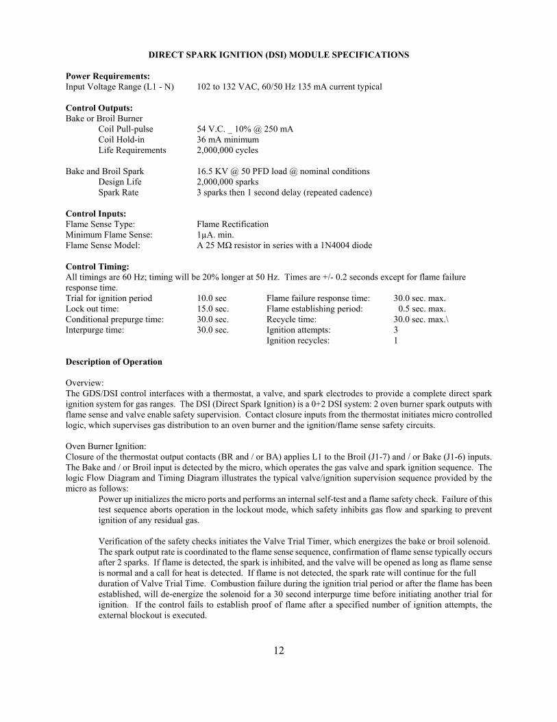
DIRECT SPARK IGNITION (DSI) MODULE SPECIFICATIONS
Power Requirements: Input Voltage Range (L1 - N) 102 to 132 VAC, 60/50 Hz 135 mA current typical Control Outputs: Bake or Broil Burner
Coil Pull-pulse 54 V.C. _ 10% @ 250 mA Coil Hold-in 36 mA minimum Life Requirements 2,000,000 cycles
Bake and Broil Spark 16.5 KV @ 50 PFD load @ nominal conditions
Design Life 2,000,000 sparks Spark Rate 3 sparks then 1 second delay (repeated cadence)
Control Inputs: Flame Sense Type: Flame Rectification Minimum Flame Sense: 1µA. min. Flame Sense Model: A 25 MΩ resistor in series with a 1N4004 diode Control Timing: All timings are 60 Hz; timing will be 20% longer at 50 Hz. Times are +/- 0.2 seconds except for flame failure response time. Trial for ignition period 10.0 sec Flame failure response time: 30.0 sec. max. Lock out time: 15.0 sec. Flame establishing period: 0.5 sec. max. Conditional prepurge time: 30.0 sec. Recycle time: 30.0 sec. max.\ Interpurge time: 30.0 sec. Ignition attempts: 3
Ignition recycles: 1 Description of Operation Overview: The GDS/DSI control interfaces with a thermostat, a valve, and spark electrodes to provide a complete direct spark ignition system for gas ranges. The DSI (Direct Spark Ignition) is a 0+2 DSI system: 2 oven burner spark outputs with flame sense and valve enable safety supervision. Contact closure inputs from the thermostat initiates micro controlled logic, which supervises gas distribution to an oven burner and the ignition/flame sense safety circuits. Oven Burner Ignition: Closure of the thermostat output contacts (BR and / or BA) applies L1 to the Broil (J1-7) and / or Bake (J1-6) inputs. The Bake and / or Broil input is detected by the micro, which operates the gas valve and spark ignition sequence. The logic Flow Diagram and Timing Diagram illustrates the typical valve/ignition supervision sequence provided by the micro as follows:
Power up initializes the micro ports and performs an internal self-test and a flame safety check. Failure of this test sequence aborts operation in the lockout mode, which safety inhibits gas flow and sparking to prevent ignition of any residual gas.
Verification of the safety checks initiates the Valve Trial Timer, which energizes the bake or broil solenoid. The spark output rate is coordinated to the flame sense sequence, confirmation of flame sense typically occurs after 2 sparks. If flame is detected, the spark is inhibited, and the valve will be opened as long as flame sense
is normal and a call for heat is detected. If flame is not detected, the spark rate will continue for the full duration of Valve Trial Time. Combustion failure during the ignition trial period or after the flame has been
established, will de-energize the solenoid for a 30 second interpurge time before initiating another trial for ignition. If the control fails to establish proof of flame after a specified number of ignition attempts, the external blockout is executed.
12

Description of Operation (con’t) Lockout: The control will lockout if any self-checks fail during normal operation. Also, the control will lockout if it failed to ignite gas after the selected number of ignition attempts or ignition recycles. In lockout the valve and ignition means are turned off. The control must be manually reset be cycling bake or broil off and back on. Flame with Gas Valve Off: If there is proof of flame for ten seconds with the gas valve off, the control will go to lockout. If there is flame for less than ten seconds, the control will reset.
13

TIMING DIAGRAM: NORMAL IGNITION CYCLE (On initial power up, there will be a 30-60 second for the electronics to reset before ignition.)
0sec 60sec 120sec Line Power
Call for Bake 7sec 7sec Status 40 sec PrePurge Trial 40 sec Interpurge Trial BA Valve Enable
TIMING DIAGRAM: POWER UP CYCLE - IGNITION, FLAME LOSS
0sec 60sec 120sec
Line Power
7sec Flame Status 40 sec PrePurge Trial present Flame Loss Lockout Call for Bake BA Valve Enable
Flame Status
14

COMPONENTS (With color coded wires) DOOR LOCK CONTROL / TIMER VGSC306 Function: The Door Lock Control / Timer is activated by the line voltage at the “SEL” contact (red/white-120vac). Relay “RL1" and “RL2"close, providing voltage to the Door Lock Motor. The relays stay closed until 10 seconds after Sensor #3 (white/green) receives a signal that the Door Lock is fully closed. Once this happens relay “RL2" opens to stop the Door Lock Motor. Relay “RL1" stays closed providing voltage to the Auto Reset Thermostat. Relays “RL3" and “RL4" close powering the Cooling Fan Motor and Cycle Relay. “RL3" and “RL4" will stay closed for approximately 3 ½ hours unless power is interrupted to Sensor #3 or SEL. In which case “RL3" and “RL4" will open, interrupting the clean cycle and Cooling Fan, and “RL2" will close, opening the Door Lock. “RL2" will stay closed until 2 seconds after Sensor #4 is powered. DOOR LOCK VGSC306 Function: When the Door Lock Motor is powered it turns a cam which pulls back a lever. As the lever moves back it allows a micro switch SW1 to open. When the lever reaches the fully closed position it closes a double stacked micro switch SW2 and SW3. Door Lock Switch SW2 completes the circuit to sensor #3 on the Door Lock Control/Timer board. After 10 seconds LS1-M1 opens, stopping the Door Lock motion. Door Lock Switch #3 closes T1-T2 and T3-T4 energizing the DSI Module pin #7 (broil) through the Selector Switch contacts 4 and 8 to the NC contacts on the Thermostat, to SW3 on the Door Lock assembly, to T1/T2 switch on the Clean Timer to the cycle contacts of the Thermostat 1 & 2 to L2. 15

COMPONENTS (con’t) COOLING FAN MOTOR VGSC Gas Self-clean Ranges Function: Provides a continuous supply of cool air during self-clean cycles to keep the DOOR LOCK MOTOR and associated circuits cool. COOLING FAN LIMIT SWITCH VDSC Gas Self-clean Ranges Function: The switch has a 1/2" bi-metal disc. The two metals have a different thermal coefficient. The expansion of the two metals cause the discs to bow as it heats up. When it reaches the calibration temperature the disc snaps closed, which closes the electrical contacts. The switch closes when the temperature reaches 230°F _ 9°F and will open when temperatures are below 203°F _ 9°F. CONVECTION FAN MOTOR VGSC Gas Self-clean Ranges Function: Provides an even flow of air in the oven cavity for more even baking.
16

COMPONENTS (con’t) AUTO RESET SWITCH VGSC306 Self-clean Ranges AUTO RESET (Top) Safety Auto Reset Switch AUTO RESET (Bottom) Door Lock Auto Reset Switch. Function: The Auto Reset Switch is a single pole / double throw switch (thermostat) which is activated by a thermobulb and lever which is calibrated to 550°F _ 25°F. The Safety Auto Reset Switch (Thermostat) will open at approximately 575 / 600°F and interrupt the voltage to the DSI Module turning off the gas valve to the oven burner. Function: The Door Lock Auto Reset Switch below 575°F closes contacts 2 to 1 and energizes the Door Lock Motor. The Door Lock Auto Reset Switch above 575°F switches to contacts 1 to 3 to disable the Door Lock Motor circuit. Final below 575°F the Auto Reset Switch closes contact 1 to 2 turning off the Door Lock Motor circuit through door Lock Motor / Timer Relay LS2 - M1. The Door Lock Motor operates until 2 seconds after sensor 4 is signaled be VC that the Door Lock Switch SW1 has been closed mechanically by the door lock bolt. The Door Lock / Timer switches LS2 - M1 and LS1 - L1 opens and the timer resets. HIGH LIMIT SWITCH VGSC306 Gas Self-clean Ranges Function: The High Limit Switch (located on the clean lock bracket) is designed to keep the temperature from reaching a run away condition. The switch is a normally closed switch that will open when the temperature, at the clean lock bracket, reaches 275°F _ 9°F. The Switch contains a heater that will keep it from cycling at the high temperature. The Switch will only reset when the supply voltage to the range is interrupted. (Unplug the range cord or interrupt the voltage at the fuse / breaker box.)
17
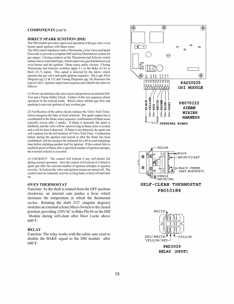
COMPONENTS (con’t) DIRECT SPARK IGNITION (DSI) The DSI module provides supervised operation of the gas valve, oven burner spark ignition with flame sense. The DSI control interfaces with a Thermostat, a Gas Valve and Spark Electrode to provide a complete DSI and Gas Distribution system for gas ranges. Closing contacts on the Thermostat and Selector switch initiate micro controlled logic, which supervises gas distribution to an oven burner and the ignition / flame sense safety circuits. Closing Thermostat and Selector switches apply L1 to the Bake (J1-6) or Broil (J1-7) inputs. This signal is detected by the micro, which operates the gas valve and spark ignition sequence. The Logic Flow Diagram (pg 12 & 13) and Timing Diagrams (pg 14) illustrates the typical valve / ignition supervision sequence provided be the micro as follows: (1) Power up initializes the micro ports and performs an internal Self-Test and a Flame Safety Check. Failure of this test sequence aborts operation in the lockout mode. Which safety inhibits gas flow and sparking to prevent ignition of any residual gas. (2) Verification of the safety checks initiates the Valve Trail Timer, which energizes the bake or broil solenoid. The spark output rate is coordinated to the flame sense sequence, confirmation of flame sense typically occurs after 2 sparks. If flame is detected, the spark is inhibited, and the valve will be open as long as flame sense is normal and a call for heat is detected. If flame is not detected, the spark rate will continue for the full duration of Valve Trail Time. Combustion failure during the ignition trail period or after the flame has been established, will de-energize the solenoid for a 40 second interpurge time before initiating another trail for ignition. If the control fails to establish proof of flame after a specified number of ignition attempts, the external lockout is executed. (3) LOCKOUT: The control will lockout if any self-checks fail during normal operation. Also the control will lockout if it failed to ignite gas after the selected number of ignition attempts or ignition recycles. In lockout the valve and ignition means are turned off. The control must be manually reset be cycling bake or broil off and back on. OVEN THERMOSTAT Function: As the shaft is rotated from the OFF position clockwise, an internal cam pushes a lever which increases the temperature at which the thermostat cycles.. Rotating the shaft 212° (angular degrees) switches an external (clean) Micro Switch to the closed position, providing 120VAC to Bake Pin #6 on the DSI Module during self-clean after Door Locks above 600°F. RELAY Function: The relay works with the safety auto reset to disable the BAKE signal to the DSI module after 600°F.
18

COMPONENTS (con’t ) GAS VALVES - BAKE OR BROIL Function: The Bake or Broil gas valve receives a voltage (approximately 22 volts DC) from the Direct Spark Ignition Module to open the valve and supply gas to the oven burner. (Operating voltage is from 10 / 12 volts DC.). HALOGEN LIGHT TRANSFORMER Function: Provides power for the oven Halogen Lights. RE-IGNITION MODULE Function: Used in series with a spark ignition switch and an electrode to provide a high voltage spark at the surface burners for gas combustion. The Re-ignition Module will send a spark to the surface burner electrodes when there is no flame sensed at the electrode. SPARK IGNITION SWITCH Function: Completes the circuit to the spark module for ignition of the surface burners. Rotating the surface burner control to any on position will cause a spark at the surface burner electrode.
19
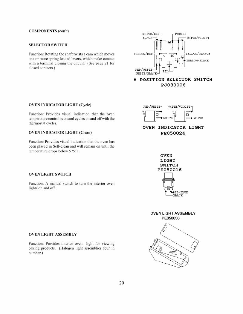
COMPONENTS (con’t) SELECTOR SWITCH Function: Rotating the shaft twists a cam which moves one or more spring loaded levers, which make contact with a terminal closing the circuit. (See page 21 for closed contacts.) OVEN INDICATOR LIGHT (Cycle) Function: Provides visual indication that the oven temperature control is on and cycles on and off with the thermostat cycles. OVEN INDICATOR LIGHT (Clean) Function: Provides visual indication that the oven has been placed in Self-clean and will remain on until the temperature drops below 575°F. OVEN LIGHT SWITCH Function: A manual switch to turn the interior oven lights on and off. OVEN LIGHT ASSEMBLY Function: Provides interior oven light for viewing baking products. (Halogen light assemblies four in number.)
20
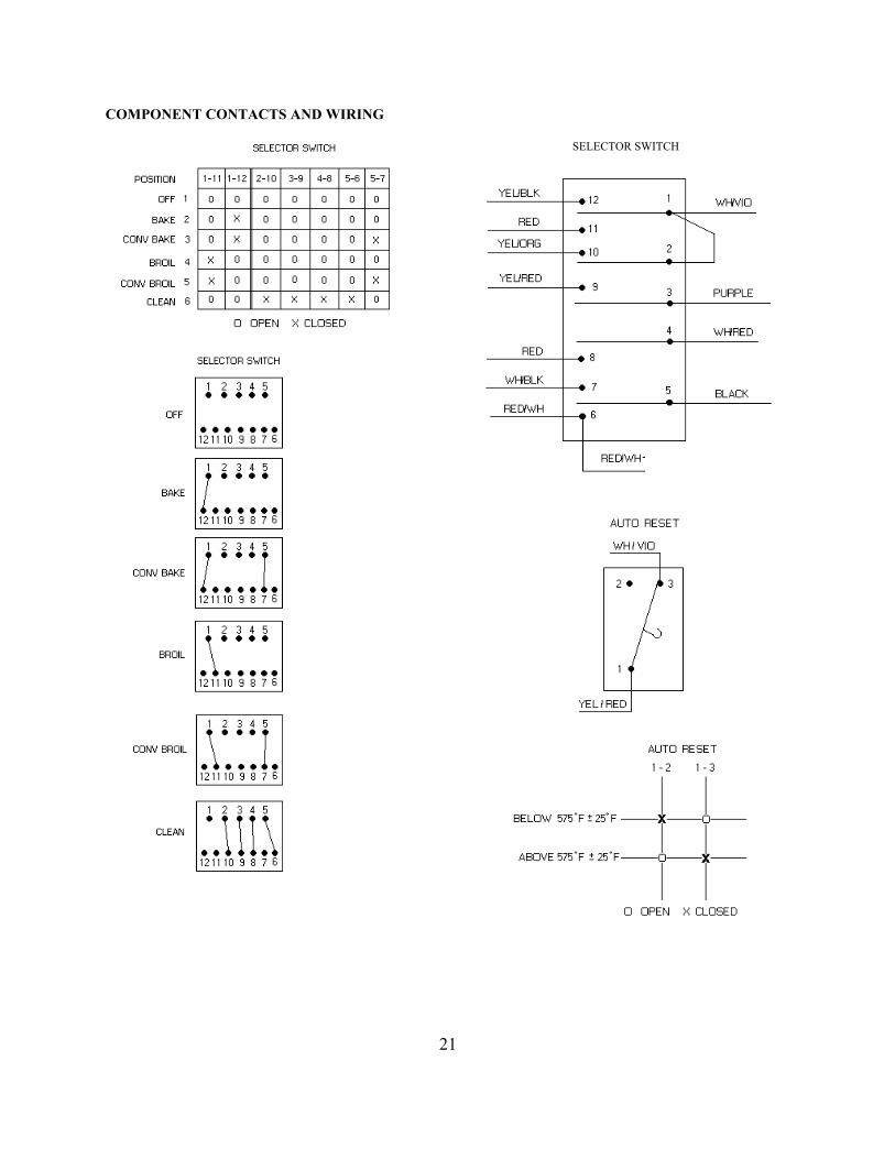
COMPONENT CONTACTS AND WIRING SELECTOR SWITCH
21
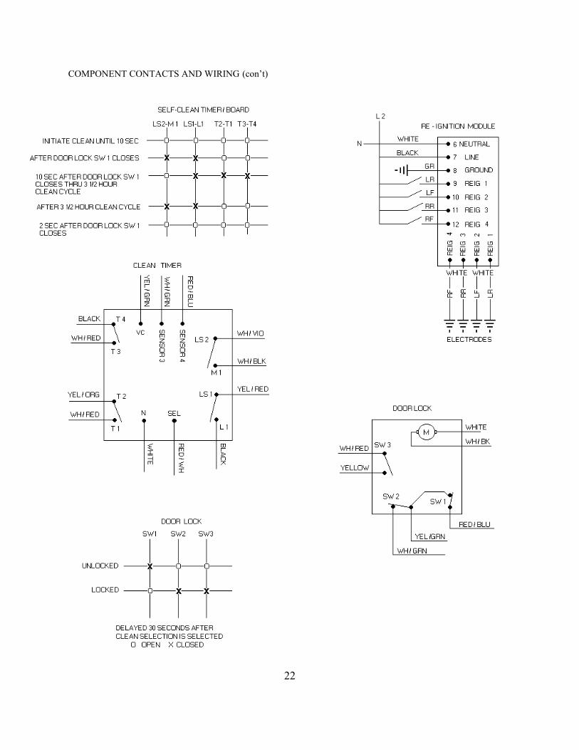
COMPONENT CONTACTS AND WIRING (con’t)
22

WIRING DIAGRAM GAS SELF-CLEAN
BAKE
BAKE MODE: Turn the selector switch to the BAKE POSITION, closing SELECTOR SWITCH contacts 1 & 12. Turning the temperature control to the desired temperature will close THERMOSTAT contacts 1 & 2. The CYCLE LIGHT will come on and cycle with the THERMOSTAT when the desired temperature is reached and will go off and on with the cycle of the thermostat to maintain the desired temperature. The contacts 1 & 2 will remain closed on the AUTO RESET until the temperature raises beyond 600°F. L1 voltage is applied to BAKE input (pin 6) on the module. The BAKE input is detected by the micro, which operates the BAKE VALVE and SPARK IGNITION sequence. (See pages 12 and 13 for a full description of operation and page 14 for the timing sequence.)
23

WIRING DIAGRAM GAS SELF-CLEAN
CONVECTION BAKE
CONVECTION BAKE MODE: Turn the selector switch to the CONV. BAKE POSITION, closing SELECTOR SWITCH contacts 1 & 12 and 5 &7. Contacts 1 & 12 supplies L1 voltage to the MODULE. Contacts 5 & 7 supplies L1 voltage to the CONVECTION FAN MOTOR. Turning the temperature control to the desired temperature will close THERMOSTAT contacts 1 & 2. The CYCLE LIGHT will come on and cycle with the THERMOSTAT when the desired temperature is reached and will go off and on with the cycle of the thermostat to maintain the desired temperature. Contact 1 & 2 will remain closed on the AUTO RESET until the temperature raises beyond 600°F. L1 voltage is applied to BAKE input (pin 6) on the module. The BAKE input is detected by the micro, which operates the BAKE VALVE and SPARK IGNITION sequence. (See pages 12 and 13 for a full description of operation and page 14 for the timing sequence.)
24
WIRING DIAGRAM GAS SELF-CLEAN
BROIL
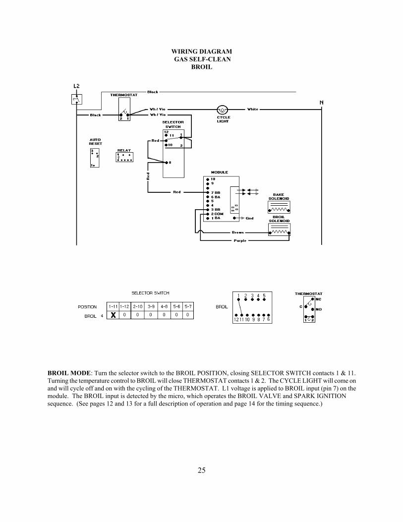
BROIL MODE: Turn the selector switch to the BROIL POSITION, closing SELECTOR SWITCH contacts 1 & 11. Turning the temperature control to BROIL will close THERMOSTAT contacts 1 & 2. The CYCLE LIGHT will come on and will cycle off and on with the cycling of the THERMOSTAT. L1 voltage is applied to BROIL input (pin 7) on the module. The BROIL input is detected by the micro, which operates the BROIL VALVE and SPARK IGNITION sequence. (See pages 12 and 13 for a full description of operation and page 14 for the timing sequence.)
25
WIRING DIAGRAM GAS SELF-CLEAN
CONVECTION BROIL
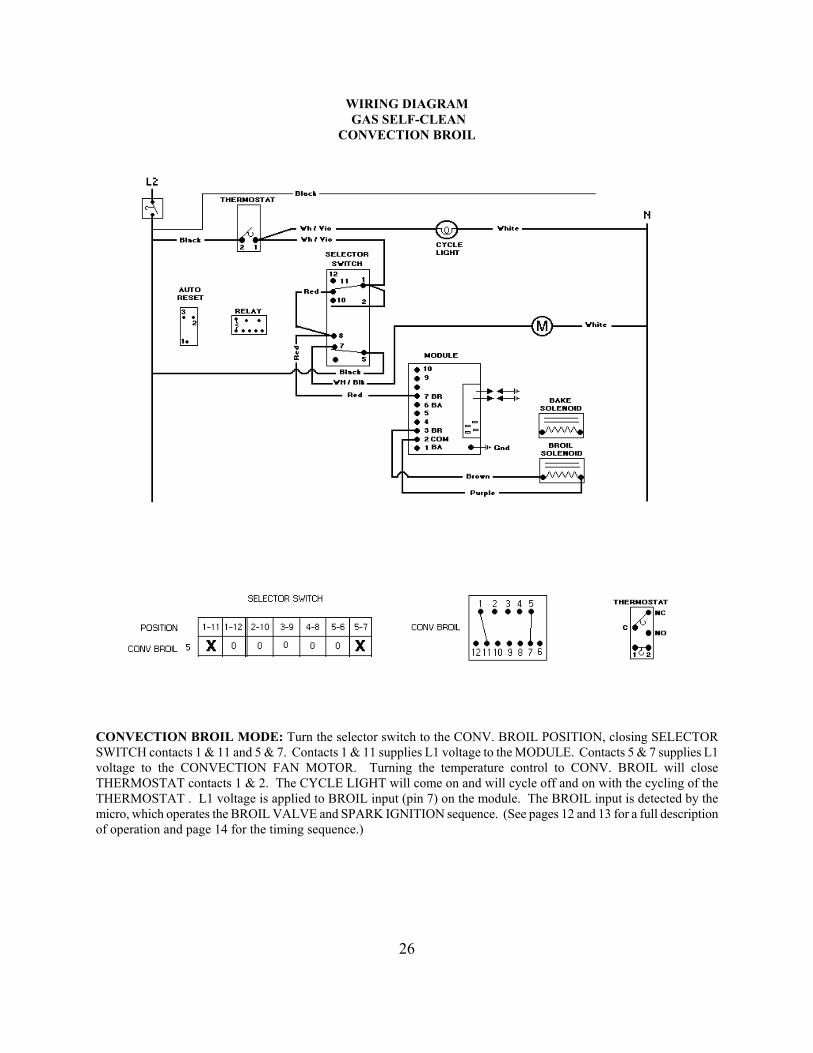
CONVECTION BROIL MODE: Turn the selector switch to the CONV. BROIL POSITION, closing SELECTOR SWITCH contacts 1 & 11 and 5 & 7. Contacts 1 & 11 supplies L1 voltage to the MODULE. Contacts 5 & 7 supplies L1 voltage to the CONVECTION FAN MOTOR. Turning the temperature control to CONV. BROIL will close THERMOSTAT contacts 1 & 2. The CYCLE LIGHT will come on and will cycle off and on with the cycling of the THERMOSTAT . L1 voltage is applied to BROIL input (pin 7) on the module. The BROIL input is detected by the micro, which operates the BROIL VALVE and SPARK IGNITION sequence. (See pages 12 and 13 for a full description of operation and page 14 for the timing sequence.)
26

WIRING DIAGRAM VGSC306 GAS SELF-CLEAN
CLEAN BEFORE DOOR LOCK
SELF-CLEAN MODE (Before the door locks): Turn the SELECTOR SWITCH to the SELF-CLEAN MODE. Turn the TEMPERATURE control past the clean setting until the knob stops. THERMOSTAT contacts 1 & 2 will close suppling L1 voltage to the SELECTOR SWITCH contacts 1 & 2. SELECTOR SWITCH contacts 2 & 10 will close suppling voltage to CLEAN/TIMER contact T2. SELECTOR SWITCH contacts 5 & 6 will close suppling voltage to CLEAN/TIMER contact SEL. and will power the relay coil. Power to SEL on the CLEAN/TIMER board will close contacts L1 & LS1 completing the circuit for the DOOR LOCK MOTOR through the AUTO RESET contacts 1 & 2 and LS2 & M1 on the CLEAN/TIMER board. This powers the DOOR LOCK MOTOR until 10 seconds after SENSOR 3 is signaled by VC that the DOOR LOCK SWITCH SW2 has been closed mechanically (along with SW3) by the DOOR LOCK BOLT.
27
WIRING DIAGRAM VGSC306 GAS SELF-CLEAN
CLEAN BEFORE 600°F AFTER DOOR LOCK
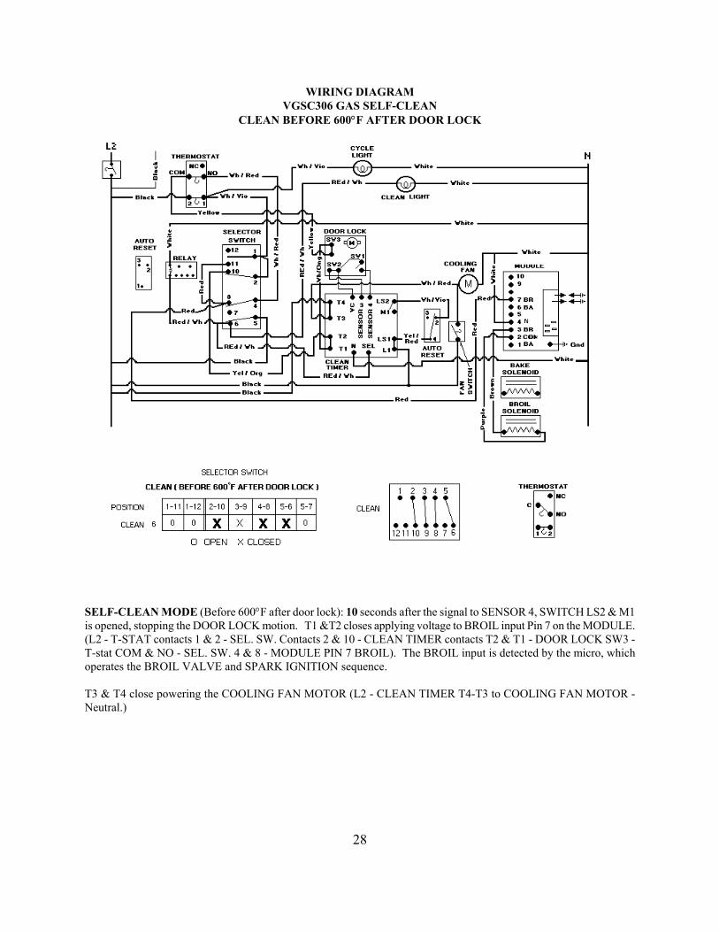
SELF-CLEAN MODE (Before 600°F after door lock): 10 seconds after the signal to SENSOR 4, SWITCH LS2 & M1 is opened, stopping the DOOR LOCK motion. T1 &T2 closes applying voltage to BROIL input Pin 7 on the MODULE. (L2 - T-STAT contacts 1 & 2 - SEL. SW. Contacts 2 & 10 - CLEAN TIMER contacts T2 & T1 - DOOR LOCK SW3 - T-stat COM & NO - SEL. SW. 4 & 8 - MODULE PIN 7 BROIL). The BROIL input is detected by the micro, which operates the BROIL VALVE and SPARK IGNITION sequence. T3 & T4 close powering the COOLING FAN MOTOR (L2 - CLEAN TIMER T4-T3 to COOLING FAN MOTOR - Neutral.)
28

WIRING DIAGRAM VGSC306 GAS SELF-CLEAN
CLEAN AFTER 600°F AFTER DOOR LOCKS
SELF-CLEAN MODE (After 600°F after door lock): L2 to THERMOSTAT, contacts 2&1, - SEL. SW. contacts 2 &10 to CLEAN TIMER contacts T2-T1 and to DOOR LOCK switch SW3 to THERMOSTAT contacts COM & NC to SEL. SW. contacts 3 & 9 to BAKE RELAY to MODULE pin 6 (Bake). The BAKE input is detected by the micro which operates the BAKE VALVE and SPARK IGNITION sequence. After approximately 3 ½ hours the CLEAN TIMER board will time out and will terminate the cycle. The temperature and the selector switch is to be turned OFF. 30 minutes will be required for the oven to cool enough for the door latch to disengage.
29
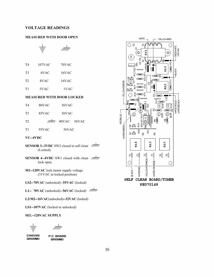
VOLTAGE READINGS MEASURED WITH DOOR OPEN
T4 107VAC 70VAC T3 4VAC 16VAC T2 4VAC 16VAC T1 5VAC 1VAC MEASURED WITH DOOR LOCKED T4 80VAC 56VAC T3 85VAC 56VAC T2 90VAC 56VAC T1 93VAC 56VAC VC--4VDC SENSOR 3--3VDC SW2 closed in self clean (Locked). SENSOR 4--4VDC SW1 closed with clean lock open. M1--120VAC lock motor supply voltage.
(31VAC in locked position) LS2--70VAC (unlocked)--55VAC (locked) L1-- 70VAC (unlocked)--56VAC (locked) L2/M2--16VAC(unlocked)--32VAC (locked) LS1--107VAC (locked or unlocked) SEL--120VAC SUPPLY
30

DOOR REMOVAL 1. Open the door approximately 15° to 20° then slowly pull upward until the door stop (A) pops out of the door socket. Gently close the door until the door stops rest against one of the stop notches (C). Slide the door up until completely free of the hinge arms.
When the door stops pop out of the door too soon the door will not slide off. When this happens:
a) Lower the door until the door stops disappear into the door;
A. DOOR (Vertical adjustment screw) B. DOOR STOP (Holds hinge in place while
removing or replacing the door)
C. DOOR HINGE SPRING (Color denotes part number)
b) Grasp the door near the lower end; c) Place your thumbs over the door socket
openings to prevent the door stops from popping out;
d) Hold the door stops in the door while sliding the door up approximately 3 inches;
e) Release the door stops and gently close the door until the door stops rest against one of the stop notches.
2. To replace the door, place the hinge arms into the door sockets. Slide the door down close to the door stops and release the pressure from the stop notches. Slowly lower the door down completely allowing the door stops to retract into the door socket.
31
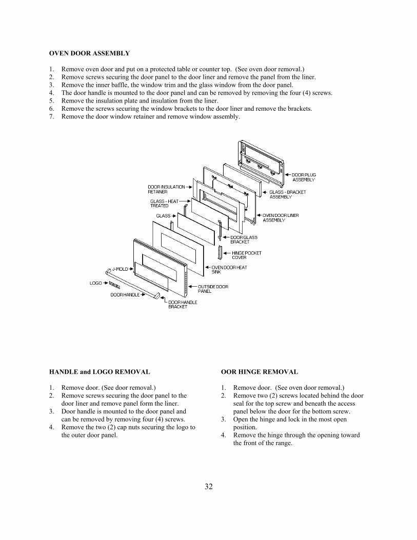
OVEN DOOR ASSEMBLY 1. Remove oven door and put on a protected table or counter top. (See oven door removal.) 2. Remove screws securing the door panel to the door liner and remove the panel from the liner. 3. Remove the inner baffle, the window trim and the glass window from the door panel. 4. The door handle is mounted to the door panel and can be removed by removing the four (4) screws. 5. Remove the insulation plate and insulation from the liner. 6. Remove the screws securing the window brackets to the door liner and remove the brackets. 7. Remove the door window retainer and remove window assembly. HANDLE and LOGO REMOVAL 1. Remove door. (See door removal.) 2. Remove screws securing the door panel to the door liner and remove panel form the liner. 3. Door handle is mounted to the door panel and can be removed by removing four (4) screws. 4. Remove the two (2) cap nuts securing the logo to the outer door panel.
OOR HINGE REMOVAL 1. Remove door. (See oven door removal.) 2. Remove two (2) screws located behind the door seal for the top screw and beneath the access panel below the door for the bottom screw. 3. Open the hinge and lock in the most open position. 4. Remove the hinge through the opening toward the front of the range.
32

COMPONENT LOCATION
33
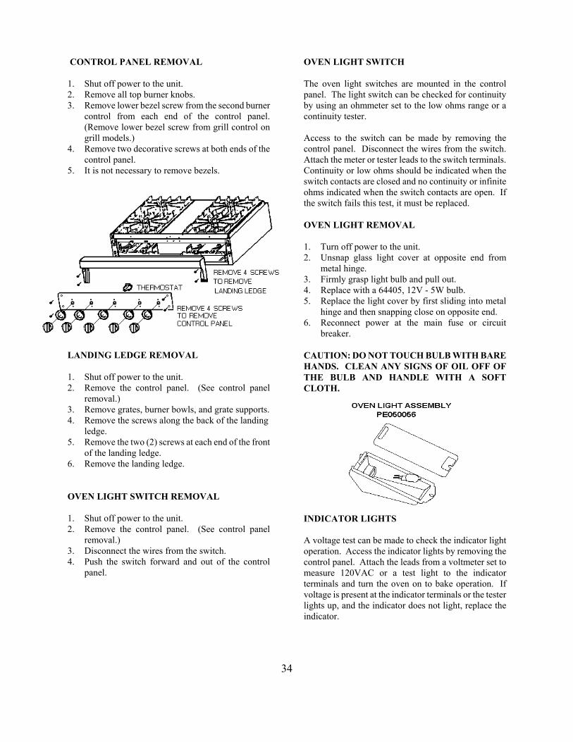
CONTROL PANEL REMOVAL 1. Shut off power to the unit. 2. Remove all top burner knobs. 3. Remove lower bezel screw from the second burner control from each end of the control panel. (Remove lower bezel screw from grill control on grill models.) 4. Remove two decorative screws at both ends of the
control panel. 5. It is not necessary to remove bezels.
LANDING LEDGE REMOVAL 1. Shut off power to the unit. 2. Remove the control panel. (See control panel removal.) 3. Remove grates, burner bowls, and grate supports. 4. Remove the screws along the back of the landing
ledge. 5. Remove the two (2) screws at each end of the front
of the landing ledge. 6. Remove the landing ledge. OVEN LIGHT SWITCH REMOVAL 1. Shut off power to the unit. 2. Remove the control panel. (See control panel removal.) 3. Disconnect the wires from the switch. 4. Push the switch forward and out of the control panel.
OVEN LIGHT SWITCH The oven light switches are mounted in the control panel. The light switch can be checked for continuity by using an ohmmeter set to the low ohms range or a continuity tester. Access to the switch can be made by removing the control panel. Disconnect the wires from the switch. Attach the meter or tester leads to the switch terminals. Continuity or low ohms should be indicated when the switch contacts are closed and no continuity or infinite ohms indicated when the switch contacts are open. If the switch fails this test, it must be replaced. OVEN LIGHT REMOVAL 1. Turn off power to the unit. 2. Unsnap glass light cover at opposite end from metal hinge. 3. Firmly grasp light bulb and pull out. 4. Replace with a 64405, 12V - 5W bulb. 5. Replace the light cover by first sliding into metal hinge and then snapping close on opposite end. 6. Reconnect power at the main fuse or circuit breaker. CAUTION: DO NOT TOUCH BULB WITH BARE HANDS. CLEAN ANY SIGNS OF OIL OFF OF THE BULB AND HANDLE WITH A SOFT CLOTH. INDICATOR LIGHTS A voltage test can be made to check the indicator light operation. Access the indicator lights by removing the control panel. Attach the leads from a voltmeter set to measure 120VAC or a test light to the indicator terminals and turn the oven on to bake operation. If voltage is present at the indicator terminals or the tester lights up, and the indicator does not light, replace the indicator.
34

TOP BURNER REMOVAL 1. Shut off power to the oven. 2. Remove grates, burner bowls and grate supports. 3. Remove the phillip head screw near the burner head securing the burner to the burner support. 4. Lift the burner and venturi assembly and remove the wire from the bottom of the ignitor. 5. Both burner assemblies (front and read) can be removed together by removing one (1) screw at the rear of the burner support, remove both ignitor wires and lift the burner support assembly. TOP BURNER IGNITOR REMOVAL 1. Shut off power to the oven. 2. Remove grate and burner bowl. 3. Remove two (2) screws securing the ignitor to the burner support. 4. Disconnect the ignitor wire. SPARK MODULE REMOVAL NOTE: FOUR BURNER MODELS WITH OR WITHOUT A GRIDDLE USE ONLY ONE (1) SPARK MODULE; FOUR (4) BURNERS WITH A CHAR- GRILL REQUIRES TWO (2) SPARK MODULES. 1. Remove grates, grate supports and center spacer. 2. Remove spark module cover. 3. Remove two (2) screws securing the spark module using care not to damage wiring. 4. Disconnect the wiring. (When replacing module do not forget to ground green wire to chassis.) 5. For wiring sequence see wiring on page 22..
BURNER BOX SECTION
INFRARED BURNER BROIL BURNER REMOVAL 1. Shut off power to the unit. 2. Shut off the gas supply. 3. Remove the two (2) broil ignitor mounting screws
and remove the ignitor from the broil burner 4. Remove the broil burner brackets. 5. Remove the broil burner mounting screws securing the burner to the oven cavity. 6.. Remove the broil burner. BROIL IGNITOR REMOVAL 1. Shut off power to the oven. 2. Remove the two (2) broil ignitor mounting screws and pull the ignitor leads into the oven cavity. 3. Disconnect the wire leads.
35

TOP BURNER VALVES VALVE REPLACEMENT 1. Remove the control panel. (See control panel removal.) 2. Remove the lower valve bolt and gasket. 3. Lift the valve from the manifold. NOTE: CHECK ALL CONNECTIONS FOR LEAKS USING A SOAP SOLUTION AFTER INSTALLING THE REPLACEMENT VALVE. PRESSURE REGULATOR REMOVAL 1. Shut off power to the oven. 2. Shut off gas supply to the oven. 3. Remove the left side grates, burner bowls and grate supports. 4. Disconnect the gas supply to the oven. 5. Remove the regulator with a pipe wench turning counter clock wise. (Secure the manifold with another wrench before turning.)
OVEN BURNER REMOVAL 1. Shut off power to the oven. 2. Remove the oven door. (See oven door removal.) 3. Remove oven racks and rack supports. 4. Remove oven bottom assembly. 5. Remove two (2) screws securing the oven burner. 6. Remove the oven burner by pulling up and out of the oven cavity. NOTE: CHECK ALL CONNECTIONS FOR LEAKS USING A SOAP SOLUTION AFTER INSTALLING REPLACEMENT REGULATOR. USE SEALANT ON ALL PIPE JOINTS. SEALANT MUST BE RESISTIVE TO L.P. GAS. DO NOT USE THREAD TAPE. CONVECTION FAN REMOVAL 1. Shut off power to the oven. 2. Remove the door. (See oven door removal.) 3. Remove the oven racks. 4. Remove the hex head screws securing the fan cover to the rear wall of the oven 5. Remove the hex head screws securing the fan mounting box to the rear wall of the oven, (being careful not to allow the motor wires to come loose and fall behind the rear wall of the oven) disconnect the wiring one lead at a time and connect to the appropriate terminal on the replacement fan motor.
36
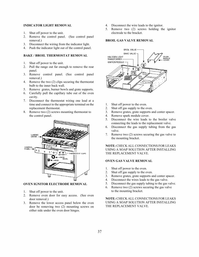
INDICATOR LIGHT REMOVAL 1. Shut off power to the unit. 2. Remove the control panel. (See control panel removal.) 3. Disconnect the wiring from the indicator light. 4. Push the indicator light out of the control panel. BAKE / BROIL THERMOSTAT REMOVAL 1. Shut off power to the unit. 2. Pull the range out far enough to remove the rear panel. 3. Remove control panel. (See control panel removal.) 4. Remove the two (2) clips securing the thermostat bulb to the inner back wall. 5. Remove grates, burner bowls and grate supports. 6. Carefully pull the capillary tube out of the oven cavity. 7. Disconnect the thermostat wiring one lead at a time and connect to the appropriate terminal on the replacement thermostat. 8. Remove two (2) screws mounting thermostat to
the control panel.
OVEN IGNITOR ELECTRODE REMOVAL 1. Shut off power to the unit. 2. Remove oven door for easy access. (See oven door removal.) 3. Remove the lower access panel below the oven door be removing two (2) mounting screws on either side under the oven door hinges.
4. Disconnect the wire leads to the ignitor. 5. Remove two (2) screws holding the ignitor electrode to the bracket. BROIL GAS VALVE REMOVAL
1. Shut off power to the oven. 2. Shut off gas supply to the oven. 3. Remove grates, grate supports and center spacer. 4. Remove spark module cover. 5. Disconnect the wire leads to the broiler valve connecting the leads to the replacement valve. 6. Disconnect the gas supply tubing from the gas valve. 7. Remove two (2) screws securing the gas valve to the mounting bracket. NOTE: CHECK ALL CONNECTIONS FOR LEAKS USING A SOAP SOLUTION AFTER INSTALLING THE REPLACEMENT VALVE. OVEN GAS VALVE REMOVAL 1. Shut off power to the oven. 2. Shut off gas supply to the oven. 3. Remove grates, grate supports and center spacer. 4. Disconnect the wires leads to the gas valve. 5. Disconnect the gas supply tubing to the gas valve. 6. Remove two (2) screws securing the gas valve
to the mounting bracket. NOTE: CHECK ALL CONNECTIONS FOR LEAKS USING A SOAP SOLUTION AFTER INSTALLING THE REPLACEMENT VALVE.
37

FREESTANDING GAS SELF-CLEAN RANGE
ACCESS TO THE SELF-CLEAN ELECTRONIC CIRCUIT FOR REPAIR Remove the range from the cabinet and remove the back cover to service the electronic components for self - clean. A. Remove the rear cover. B. Disconnect power to the unit. C. Disconnect the gas supply to the unit.
COMPONENT LOCATION A. Flue assembly. B. Cooling fan duct. C. Broiler flue assembly. D. Relay. E. Cooling fan F. Direct Spark Ignition (DSI) module. G. Self-clean timer PC board. H. Auto reset (safety). J. Terminal board. K. Auto reset (self-clean).
38

FREESTANDING GAS SELF-CLEAN LOCK To replace the self-clean lock mechanism you will need to remove the following:
H. Landing ledge. J. Control panel K. Knob bezels. L. Knobs. (Continued on next page)
A. Burner gates and center grate. B. Burner bowls. C. Burner caps. D. Grate supports and center spacer. E. Grate support trim. F. Side panels. G. Lower access panel.
39
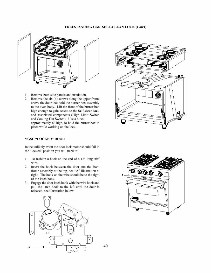
FREESTANDING GAS SELF-CLEAN LOCK (Con’t)
1. Remove both side panels and insulation. 2. Remove the six (6) screws along the upper frame above the door that hold the burner box assembly to the oven body. Lift the front of the burner box high enough to gain access to the Self-clean lock and associated components (High Limit Switch and Cooling Fan Switch). Use a block,
approximately 6" high, to hold the burner box in place while working on the lock. VGSC “LOCKED” DOOR In the unlikely event the door lock motor should fail in the “locked” position you will need to: 1. To fashion a hook on the end of a 12" long stiff wire. 2. Insert the hook between the door and the front frame assembly at the top, see “A” illustration at right. The hook on the wire should be to the right
of the latch hook. 3. Engage the door latch hook with the wire hook and pull the latch hook to the left until the door is released, see illustration below.
40

TROUBLE SHOOTING GUIDE --GSC SELF-CLEAN FREESTANDING RANGE
PROBLEM PROBABLE CAUSE CORRECTION BAKE SHUTS OFF Control Board is Locked Out (1) Turn off selector switch (2)Turn off
Selector Switch to Bake (If flame is not detected, the external Temperature Control (3)Position igniter Baking Temperature Set LOCKOUT is executed). (4) Adjust Air Shutter (5) Turn on Selector Cycle Light is On Switch (6) Turn on Temperature Control
Range Completely Inoperative No supply voltage to range Check fuse / breaker box Electrically No voltage to range circuits Check high limit switch
1. No Bake: 1A. No voltage to Thermostat. 1A. Check for 120VAC at the Selector Switch to Bake Thermostat terminals BA to Baking Temperature set Neutral. If no voltage is present
No Cycle Light check for broken or burned wires. 1B. Defective T-stat contacts. 1B. Check continuity across
contacts BA to Neutral. Contacts open, Replace T-stat. 2. No Bake: 2A. Selector Switch contacts 2A. Check continuity at contacts
Selector Switch to Bake 1 to 12 open. 1 to 12 on Selector Switch. Baking Temperature set Open contacts, replace
Cycle Light is on Selector Switch. 2B. Safety Reset Relay contacts 2B. Check continuity at contacts
1 to 2 open. 1 to 2 on Safety Auto Reset, Open contacts, replace Safety Auto Reset.
3. No Bake: 3A. Direct Spark Ignition Module 3A Check for 120VAC to pin #6
Selector Switch to Bake (DSI) inoperative. (BA / Yel). 120VAC present, Baking Temperature set Replace DSI module.
Cycle Light is on Bake Ignitor does not click
4. No Bake: 4A. Open coil in the Bake Solenoid 4A. Check continuity across the
Selector Switch to Bake valve. Solenoid coils, If open replace Baking Temperature set the Solenoid Gas Valve. Cycle Light is on When the coil is okay check Bake Ignitor clicks the wiring. Gas supply tubing on wrong 4B. Air in the gas line. 4B. Purge the Gas Line, turn
Gas Valve control off and retry.
5. No Convection Bake: 5A. Open contacts in the Selector 5A. Check continuity from 5 to 7 Bake functions normally Switch. on the Selector Switch. If
open replace Selector Switch. 5B. Open Motor windings in the 5B. Check continuity across the
Convection Fan Motor. Motor windings. If open replace Motor. Check wiring.
6. No broil: 6A. Open contacts in the Selector 6A. Check continuity from 1 to 11
Selector Switch set to Broil Switch. on the Selector Switch. If Temperature set to Broil open replace Selector Switch. Bake functions normally Check wiring.
Cycle Light is on 6B. Direct Spark Ignition Module 6B. Check for120VAC at pin 7 Broil Ignitor does not click (DSI) inoperative. (BR / RED) on the Module.
Gas supply tubing on wrong If voltage is present, replace Gas Valve Module. No voltage check
wiring.
See Description of Operation, pages 12, 13, and 14.
Electronic Protection Devices make use of a flame electrode as a sensor and an electronic amplifier to boost the small current
41
involved to operate a relay. The advantage of these units over thermal expansion or thermoelectric devices are: (1) they are not activated by heat, only flame; (2) they respond quickly to the presence of flame, or flame failure; (3) they can be positioned to provide pilot proving, at the ignition point of the flame; (4) the electrode has a longer working life. Both systems rely on the ability to conduct and electrical current, during the combustion process. Large numbers of free electrons and ions are present in the flame, so the flame acts as an electrolyte in which the current can flow. The ions and electrons are attached to suitable charged electrodes. Current of approximately 4 to 12 micro - amps may be conducted.
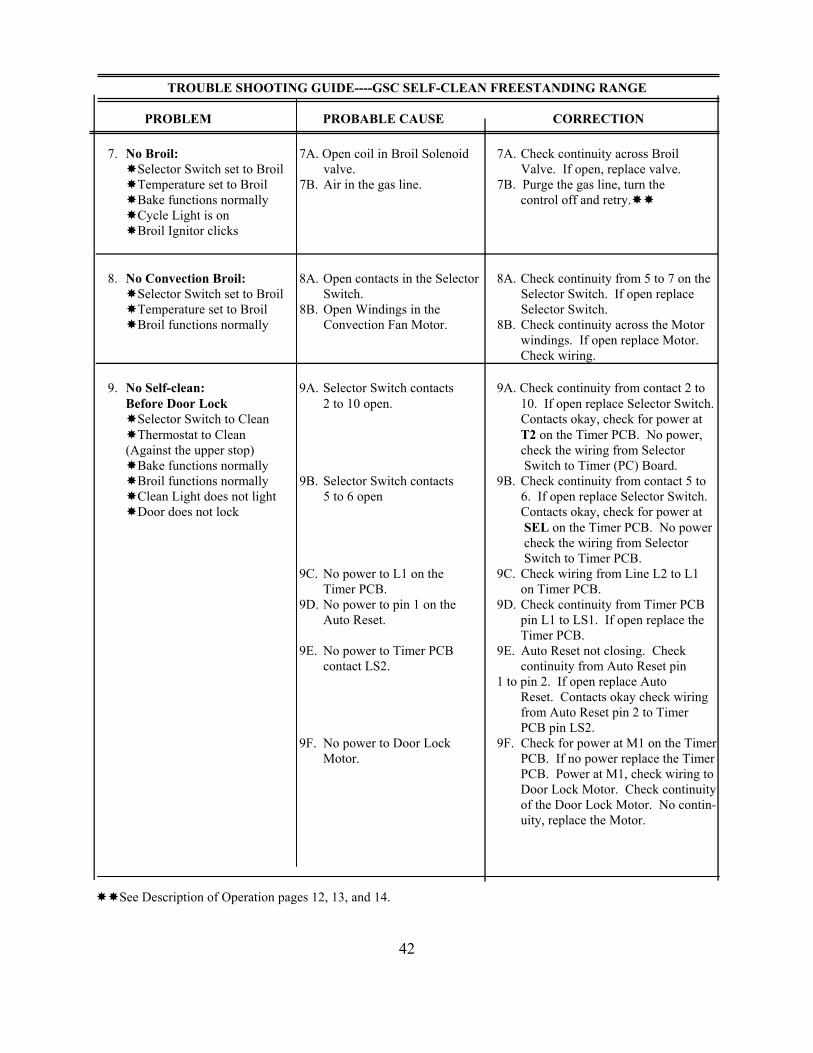
TROUBLE SHOOTING GUIDE----GSC SELF-CLEAN FREESTANDING RANGE
PROBLEM PROBABLE CAUSE CORRECTION 7. No Broil: 7A. Open coil in Broil Solenoid 7A. Check continuity across Broil
Selector Switch set to Broil valve. Valve. If open, replace valve. Temperature set to Broil 7B. Air in the gas line. 7B. Purge the gas line, turn the Bake functions normally control off and retry.
Cycle Light is on Broil Ignitor clicks
8. No Convection Broil: 8A. Open contacts in the Selector 8A. Check continuity from 5 to 7 on the Selector Switch set to Broil Switch. Selector Switch. If open replace Temperature set to Broil 8B. Open Windings in the Selector Switch. Broil functions normally Convection Fan Motor. 8B. Check continuity across the Motor
windings. If open replace Motor. Check wiring.
9. No Self-clean: 9A. Selector Switch contacts 9A. Check continuity from contact 2 to
Before Door Lock 2 to 10 open. 10. If open replace Selector Switch. Selector Switch to Clean Contacts okay, check for power at
Thermostat to Clean T2 on the Timer PCB. No power, (Against the upper stop) check the wiring from Selector
Bake functions normally Switch to Timer (PC) Board. Broil functions normally 9B. Selector Switch contacts 9B. Check continuity from contact 5 to
Clean Light does not light 5 to 6 open 6. If open replace Selector Switch. Door does not lock Contacts okay, check for power at
SEL on the Timer PCB. No power check the wiring from Selector Switch to Timer PCB.
9C. No power to L1 on the 9C. Check wiring from Line L2 to L1 Timer PCB. on Timer PCB.
9D. No power to pin 1 on the 9D. Check continuity from Timer PCB Auto Reset. pin L1 to LS1. If open replace the
Timer PCB. 9E. No power to Timer PCB 9E. Auto Reset not closing. Check
contact LS2. continuity from Auto Reset pin 1 to pin 2. If open replace Auto
Reset. Contacts okay check wiring from Auto Reset pin 2 to Timer PCB pin LS2.
9F. No power to Door Lock 9F. Check for power at M1 on the Timer Motor. PCB. If no power replace the Timer
PCB. Power at M1, check wiring to Door Lock Motor. Check continuity of the Door Lock Motor. No contin- uity, replace the Motor.
See Description of Operation pages 12, 13, and 14.
42

TROUBLE SHOOTING GUIDE----VGSC SELF-CLEAN FREESTANDING RANGE PROBLEM PROBABLE CAUSE CORRECTION 10. No Self-clean: 10A. Selector Switch contacts 10A. Check continuity from pin 2 to 10.
Before 600°F After 2 to 10 open If open replace Selector Switch. Door Lock Continuity checks okay.
Selector Switch to Clean 10B. Timer PCB open contacts 10B Check for power at T2 on the Thermostat to Clean T1 to T2. Timer PCB, no power check
(Against the upper stop) wiring from Selector Switch to Bake functions normally Timer PCB. Check continuity
Broil functions normally from T1 to T2 on Timer PCB. Clean Light is on If open replace Timer PCB. Door lock engaged 10C. Door Lock Switch SW3 10C Check for power at the COM No spark to Broil Igniter open. connection on the Microswitch
No Broil flame on the Thermostat. No power, check the Door Lock Switch SW3 for continuity. If open, replace SW3 on the Door Lock.
10D. Micro switch on the T-stat 10D. Check continuity across pin COM open. to NO. If open replace Thermostat.
10E. Selector Switch contacts 10E. Check continuity across pins 4 to 8. 4 to 8 open. Open contacts, replace Selector
Switch. Contacts okay, check the wiring from pin 8 to the DSI module.
11. Partial Self-clean: 11A. Selector Switch contacts 11A. Check continuity from pin 3 to
After 600°F After 3 to 9 open. 9 on the Selector Switch, open Door Locks Contacts replace Selector Switch Broil Burner comes on 11B. Bake Relay contacts 11B. Check continuity from pin 9 to during the first half of 9 to 6 open. 6 on the Bake Relay, open contacts Self-clean. replace Relay. Bake Burner fails to Ignite during the last half of the clean cycle. Bake functions normally
12. Cooling Fan: 12A. Timer PCB contacts T4 12A. Check continuity from T3 to T4 on
Does not come on when to T3 open. Timer PCB. If open replace the place in self-clean. Timer PCB. Contacts good check Self-clean cycle okay continuity across the Fan Motor. during initial startup. No continuity, replace the motor.
13. Cooling Fan: 13A. Fan Switch defective. 13A. Fan Switch is normally open. Does not turn off Check continuity when cold,
(The Cooling Fan will if closed, replace the Fan Switch. normally run for several minutes after a self-clean cycle, until the temperature drops to a safe level.)
43