Viking Gasifier
5
General right s Copyright and moral rights for the publications made accessible in the public portal are retained by the authors and/or other copyright owners and it is a condition of accessing publications that users recognise and abide by the legal requirements associa ted with these rights. • Users may download and print one copy of any publication from the public portal for the purpose of private study or research. • You may not f urther distribute the material or use it for any profit-making activity or commercial gain • You may freely distribute the URL identifying the publication in the public portal ? If you believe that this document breaches copyright please contact us providing details, and we will remove access to the work immediately and investigate your claim. Downloaded from orbit.dtu.dk on: Nov 08, 2015 Status - 2000 Hours of Operation with the Viking Gasifier Gøbel, Benny; Henriksen, Ulrik Birk; Ahrenfeldt, Jesper; Jensen, T.K.; Hindsgaul, Claus; Bentzen, J.D.; Sørensen, L.H. Published in: Procedings of 2nd World Conference and Technology Exhibition on Biomass for Energy and Industry Publication date: 2004 Document Version Preprint (usually an early version) Link to publication Citation (APA): Gøbel, B., Henriksen, U. B., Ahrenfeldt, J., Jensen, T. K., Hindsgaul, C., Bentzen, J. D., & Sørensen, L. H. (2004). Status - 2000 Hours of Operation with the Viking Gasifier. In W. P. M. van Swaaij, T. Fjällström, P. ¨Helm, & A. Grassi (Eds.), Procedings of 2nd World Conference and Technology Exhibition on Biomass for Energy and Industry. Rome: ETA-Florence & WIP-Munich.
Transcript of Viking Gasifier
7/24/2019 Viking Gasifier
http://slidepdf.com/reader/full/viking-gasifier 1/5
General rights Copyright and moral rights for the publications made accessible in the public portal are retained by the authors and/or other copyright ownersand it is a condition of accessing publications that users recognise and abide by the legal requirements associated with these rights.
• Users may download and print one copy of any publication from the public portal for the purpose of private study or research.
• You may not further distribute the material or use it for any profit-making activity or commercial gain
• You may freely distribute the URL identifying the publication in the public portal ?
If you believe that this document breaches copyright please contact us providing details, and we will remove access to the work immediatelyand investigate your claim.
Downloaded from orbit.dtu.dk on: Nov 08, 2015
Status - 2000 Hours of Operation with the Viking Gasifier
Gøbel, Benny; Henriksen, Ulrik Birk; Ahrenfeldt, Jesper; Jensen, T.K.; Hindsgaul, Claus; Bentzen, J.D.;Sørensen, L.H.
Published in: Procedings of 2nd World Conference and Technology Exhibition on Biomass for Energy and Industry
Publication date: 2004
Document Version Preprint (usually an early version)
Link to publication
Citation (APA): Gøbel, B., Henriksen, U. B., Ahrenfeldt, J., Jensen, T. K., Hindsgaul, C., Bentzen, J. D., & Sørensen, L. H.(2004). Status - 2000 Hours of Operation with the Viking Gasifier. In W. P. M. van Swaaij, T. Fjällström, P.¨Helm, & A. Grassi (Eds.), Procedings of 2nd World Conference and Technology Exhibition on Biomass forEnergy and Industry. Rome: ETA-Florence & WIP-Munich.

7/24/2019 Viking Gasifier
http://slidepdf.com/reader/full/viking-gasifier 2/5
STATUS–2000 HOURS OF OPERATION WITH THE VIKING GASIFIER
Gøbel, B., Henriksen, U., Ahrenfeldt, J., Jensen, T.K., Hindsgaul, C., *Bentzen, J.B., **Sørensen, L.H.
Biomass Gasification Group, Department of Mechanical Engineering,
Technical University of Denmark, 2800 Kongens Lyngby, Denmark* COWI, Parallelvej 15, 2800 Kongens Lyngby, Denmark
**ReaTech, c/o CAT, Frederiksborgvej 399, Post box 30, 4000 Roskilde, Denmark
ABSTRACT: At the Technical University of Denmark, a biomass gasification CHP test plant named “Viking” has
been constructed. The Viking plant is a two-stage gasifier. The plant was commissioned in the summer of 2002 and
as of October 2003 more than 2000 hours of operation with wood chips as fuel has been conducted. The plant is a
small scale gasifier with a nominal thermal input of 75 kW, plant and engine has been operated continuously and
unmanned for five test periods of approximately 450 hours each.
A bag house filter proved to be efficient as gas cleaning system. This cleaning device has proven to be efficient
through out several thousands hours of operation. Producer gas properties and contaminations have been
investigated closely. No tar or particles were detected in the gas. Minor deposits consisting of salts and carbonates
were observed in the hot gas heat exchangers. 25% efficiency from biomass to net electricity was obtained.
Keywords: gasification, combined heat and power generation (CHP), pilot plant
1 INTRODUCTION
Development of processes for thermal gasification of
biomass has been going on for many years. One of the
main problems has been the presence of tars in the
produced gas. Tars damage internal combustion engines,
gas turbines and other machinery. Therefore gas
cleaning and reduction of the produced tar have been
subject for lot research projects [1]. Gasification
processes producing only very low amounts of tars will
have great potential as tar treatments can be avoided [2].At the Biomass Gasification Group, MEK, DTU the
Two-stage gasification process have been developed
during he last 14 years. The main advantages of the two-
stage gasification process is, that contrary to most other
gasifiers, very small amounts of tar is present in the
produced gas. [3], [4], [5], [6].
It was decided to build a small-scale demonstration
plant for fully automatic operation for at least 1000
hours at DTU [7]. The small scale (75 kW thermal) was
chosen for economical reasons. It was decided to use
wood chips as fuel.
The gasifier called “Viking” (see figure 1) is a
traditional two-stage gasifier [8] which means that the
pyrolysis and char gasification occur in separate reactors(see figure 2).
The main target for the Viking project has been to
demonstrate and test long-term CHP operation of a
gasifier coupled with a gas engine. The plant was
commissioned in the autumn of 2002 and has as of
October 2003 been running for more than 2200 hours.
2 PROCESS AND PLANT DESCRIPTION
Figure 1: The Viking Gasifier
2.1 Process
The Viking plant is based on the two-stage
gasification principle, where pyrolysis and gasification
takes place in two separate reactors (figure 2).
Figure 2: Viking plant set-up
Drying and pyrolysis
Cooled exhaustFuel
50 °°°°C 600 °°°°C
750 °°°°C
90 °°°°C50 °°°°C
Partial
oxidation> 1100 °°°°C
Gasification
AshExhaust
superheatAir preheatParticles
Roots
blower
Condense
d water
Exhaust
D.H.D.H.
Electricity
EngineMixing
tank
50,000 mg/Nm3tar
500 mg/Nm3tar
< 5 mg/Nm3tar
25 mg/Nm3tar
Gas
7/24/2019 Viking Gasifier
http://slidepdf.com/reader/full/viking-gasifier 3/5
Between the two reactors the 600 °C hot pyrolysis
products are partial oxidised by preheated air. This
partial oxidation results in a temperature increase to
around 1100 °C at which the main part of the tar will
decompose.
By passing several heat exchangers, delivering heatfor the process and district heating, the produced gas is
cooled to 90 °C. At this temperature the soot particles
are removed dry in a simple bag house filter.
2.2 Condensate
A further cooling of the gas condenses the steam in
the gas. The toxicity of the condensate has been tested
and accepted for processing in Danish biological sewage
plants. The cooled gas is fuelled to a gas engine coupled
to a generator, producing power and district heating.
2.3 Engine
The gas engine is an integrated part of the whole
gasification plant, the excess heat from the exhaust gas
is utilised for drying and pyrolysis of the biomass in the
gasification system, and the engine directly controls the
load of the gasifier.
2.4 Tar removal
Between the pyrolysis and the gasification, the
pyrolysis products are partially oxidised by air addition.
Thus the tar contents in the volatiles are reduced by a
factor of 100 and thermal energy for the endothermic
char gasification is produced.
When the partially oxidised pyrolysis products pass
through the char bed in the char gasification reactor, the
tar contents are further reduced by a factor of 100.The resulting tar content in the produced gas is less
then 1 mg per Nm3.
3 OPERATING RESULTS
During the first year the plant was operated for 2200
hours divided into 5 test periods of approximately 450
hours of continues operation each. Between the test
periods the plant was disassembled and the system was
inspected.
In cooperation with Technical University of
Hamburg-Harburg, Germany, the performance of the
plant was examined during 400 hours of continuesoperation in April 2003.
Table I: Key data, 400 hours test, April 2003
Key data
Thermal input 68 kW
Fuel Wood chips
Moisture content 35-45 %
Gasifier efficiency 93%
Engine efficiency 32%
Electric efficiency 27%
Overall electric efficiency 25%
Tar level <1 mg/Nm3
Dust level <5 mg/Nm3
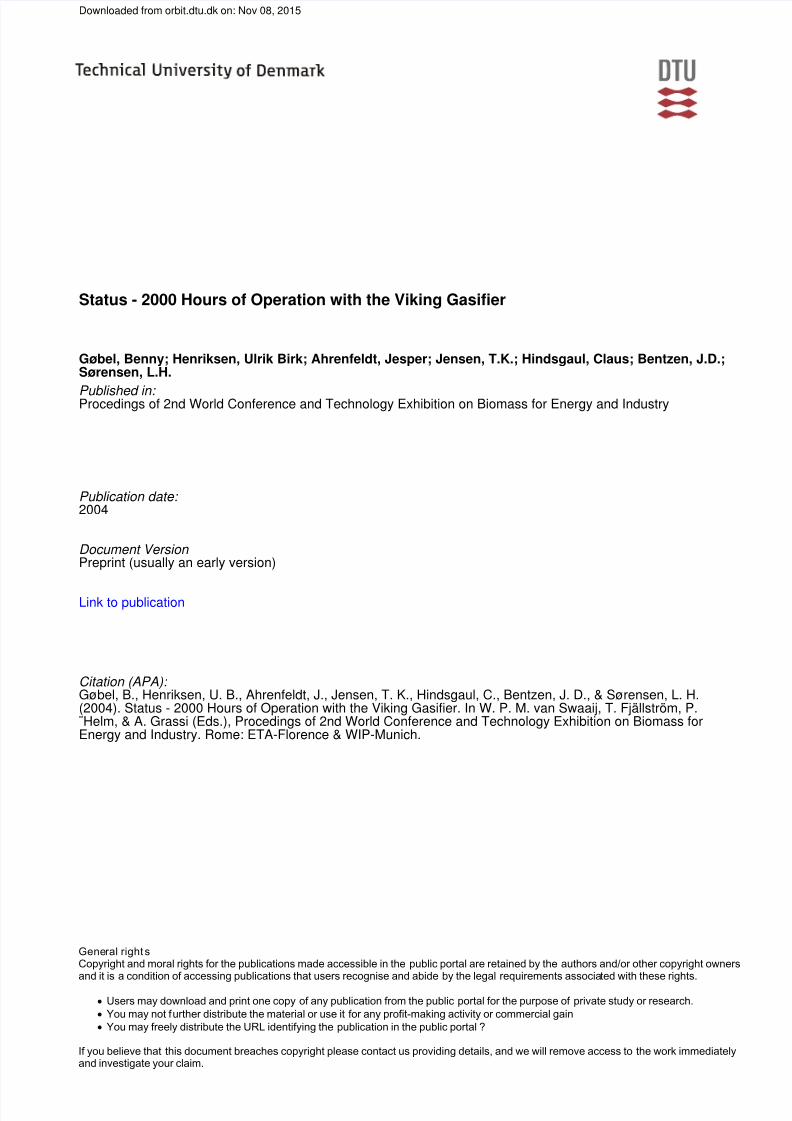
3.1 Gasifier performance during 400 hours
The gasifier was running fully automated, controlled
by a PLC, during the 400 hours test in April 2003.
During the two weeks test period the process was stable
with three close downs according blockages in the
feeding system (figure 3).
0
10
20
30
40
50
60
01-04-
200300:00
04-04-
200300:00
07-04-
200300:00
10-04-
200300:00
13-04-
200300:00
16-04-
200300:00
19-04-
200300:00
Time
flow: prod. Gas LHV Powerprod. Engine
Heating up Start up1 Start up2
Engine operation Shut down
Gas flow, m3 /h
Power, kW
LHV, MJ/Nm3
Figure 3: Plant performance during 400 hours
experiment, April 2003.
3.2 Carbon loss
Unconverted char is lost from the system during two
major sources.
• During the grate as ash particles.
• As dust removed by the bag house filter.
Minor amounts of carbon is lost by deposits in thegas system and by the clean gas delivered to the engine.
In total the carbon loss is measured to be 0.1 – 1 % of
the biomass consumption.
3.3 Tars
During this period three independent institutes
measured the tar content in the raw and cleaned gas.
Only one of them was able to measure a minor content
of tar in the raw gas (0.1 mg/Nm3 of naphthalene). The
dust content in the gas was negligible as well (< 5
mg/Nm3).
The gas produced has a very stable composition that
makes engine operation easy to handle. The unconverted
char in the ash is extremely low.
3.4 Condensate
The condensate from the gas cooler was analysed. It
was not possible to detect any harmful compounds: F-,
Cl-, NO2-, NO3
- (detection limit: 1 mg/l) PO3-, SO3
-, SO4-
(detection limit: 2 mg/l). Neither any tar-compounds
(Naphthalene and higher) was detected. The results
were compared to results from earlier investigations of
condensate from the 100 kW two-stage gasifiers [9] and
good agreement with the older experiments was found.
High amounts of ammonia, approx. 1 g/l, are seen. This
condensate can be led directly to the public sewer
system.
7/24/2019 Viking Gasifier
http://slidepdf.com/reader/full/viking-gasifier 4/5
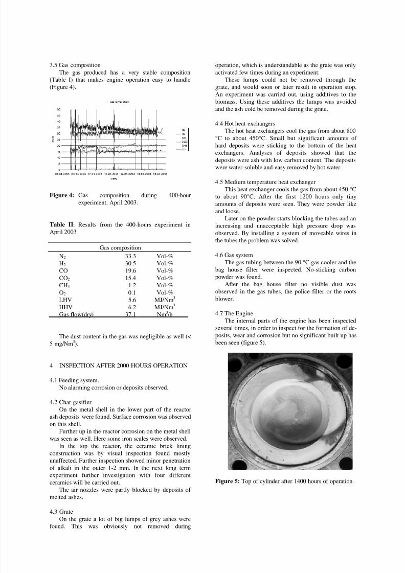
3.5 Gas composition
The gas produced has a very stable composition
(Table I) that makes engine operation easy to handle
(Figure 4).
Figure 4: Gas composition during 400-hour
experiment, April 2003.
Table II: Results from the 400-hours experiment in
April 2003
Gas composition
N2 33.3 Vol-%
H2 30.5 Vol-%
CO 19.6 Vol-%
CO2 15.4 Vol-%
CH4 1.2 Vol-%
O2 0.1 Vol-%
LHV 5.6 MJ/Nm3
HHV 6.2 MJ/Nm3
Gas flow(dry) 37.1 Nm3 /h
The dust content in the gas was negligible as well (<
5 mg/Nm3).
4 INSPECTION AFTER 2000 HOURS OPERATION
4.1 Feeding system.
No alarming corrosion or deposits observed.
4.2 Char gasifierOn the metal shell in the lower part of the reactor
ash deposits were found. Surface corrosion was observed
on this shell.
Further up in the reactor corrosion on the metal shell
was seen as well. Here some iron scales were observed.
In the top the reactor, the ceramic brick lining
construction was by visual inspection found mostly
unaffected. Further inspection showed minor penetration
of alkali in the outer 1-2 mm. In the next long term
experiment further investigation with four different
ceramics will be carried out.
The air nozzles were partly blocked by deposits of
melted ashes.
4.3 Grate
On the grate a lot of big lumps of grey ashes were
found. This was obviously not removed during
operation, which is understandable as the grate was only
activated few times during an experiment.
These lumps could not be removed through the
grate, and would soon or later result in operation stop.
An experiment was carried out, using additives to the
biomass. Using these additives the lumps was avoidedand the ash cold be removed during the grate.
4.4 Hot heat exchangers
The hot heat exchangers cool the gas from about 800
°C to about 450°C. Small but significant amounts of
hard deposits were sticking to the bottom of the heat
exchangers. Analyses of deposits showed that the
deposits were ash with low carbon content. The deposits
were water-soluble and easy removed by hot water.
4.5 Medium temperature heat exchanger
This heat exchanger cools the gas from about 450 °C
to about 90°C. After the first 1200 hours only tiny
amounts of deposits were seen. They were powder like
and loose.
Later on the powder starts blocking the tubes and an
increasing and unacceptable high pressure drop was
observed. By installing a system of moveable wires in
the tubes the problem was solved.
4.6 Gas system
The gas tubing between the 90 °C gas cooler and the
bag house filter were inspected. No-sticking carbon
powder was found.
After the bag house filter no visible dust was
observed in the gas tubes, the police filter or the roots
blower.
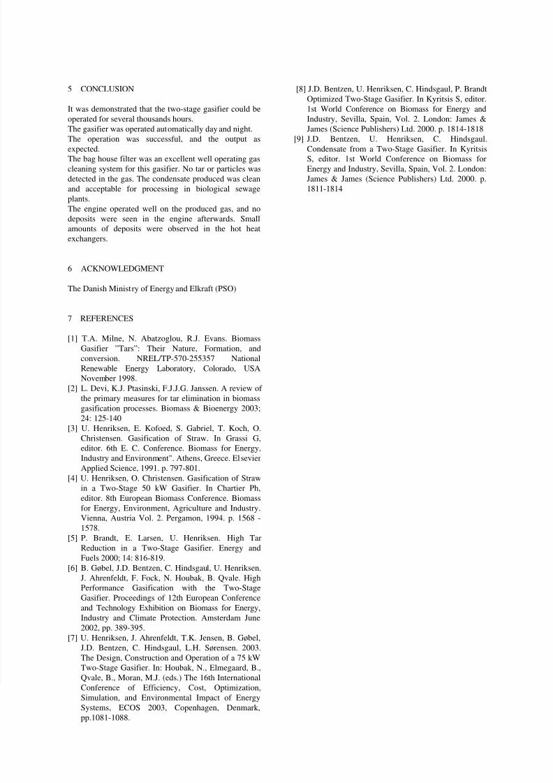
4.7 The Engine
The internal parts of the engine has been inspected
several times, in order to inspect for the formation of de-
posits, wear and corrosion but no significant built up has
been seen (figure 5).
Figure 5: Top of cylinder after 1400 hours of operation.
7/24/2019 Viking Gasifier
http://slidepdf.com/reader/full/viking-gasifier 5/5
5 CONCLUSION
It was demonstrated that the two-stage gasifier could be
operated for several thousands hours.
The gasifier was operated automatically day and night.
The operation was successful, and the output asexpected.
The bag house filter was an excellent well operating gas
cleaning system for this gasifier. No tar or particles was
detected in the gas. The condensate produced was clean
and acceptable for processing in biological sewage
plants.
The engine operated well on the produced gas, and no
deposits were seen in the engine afterwards. Small
amounts of deposits were observed in the hot heat
exchangers.
6 ACKNOWLEDGMENT
The Danish Ministry of Energy and Elkraft (PSO)
7 REFERENCES
[1] T.A. Milne, N. Abatzoglou, R.J. Evans. Biomass
Gasifier ”Tars”: Their Nature, Formation, and
conversion. NREL/TP-570-255357 National
Renewable Energy Laboratory, Colorado, USA
November 1998.
[2] L. Devi, K.J. Ptasinski, F.J.J.G. Janssen. A review of
the primary measures for tar elimination in biomass
gasification processes. Biomass & Bioenergy 2003;24: 125-140
[3] U. Henriksen, E. Kofoed, S. Gabriel, T. Koch, O.
Christensen. Gasification of Straw. In Grassi G,
editor. 6th E. C. Conference. Biomass for Energy,
Industry and Environment". Athens, Greece. Elsevier
Applied Science, 1991. p. 797-801.
[4] U. Henriksen, O. Christensen. Gasification of Straw
in a Two-Stage 50 kW Gasifier. In Chartier Ph,
editor. 8th European Biomass Conference. Biomass
for Energy, Environment, Agriculture and Industry.
Vienna, Austria Vol. 2. Pergamon, 1994. p. 1568 -
1578.
[5] P. Brandt, E. Larsen, U. Henriksen. High Tar
Reduction in a Two-Stage Gasifier. Energy andFuels 2000; 14: 816-819.
[6] B. Gøbel, J.D. Bentzen, C. Hindsgaul, U. Henriksen,
J. Ahrenfeldt, F. Fock, N. Houbak, B. Qvale. High
Performance Gasification with the Two-Stage
Gasifier. Proceedings of 12th European Conference
and Technology Exhibition on Biomass for Energy,
Industry and Climate Protection. Amsterdam June
2002, pp. 389-395.
[7] U. Henriksen, J. Ahrenfeldt, T.K. Jensen, B. Gøbel,
J.D. Bentzen, C. Hindsgaul, L.H. Sørensen. 2003.
The Design, Construction and Operation of a 75 kW
Two-Stage Gasifier. In: Houbak, N., Elmegaard, B.,
Qvale, B., Moran, M.J. (eds.) The 16th International
Conference of Efficiency, Cost, Optimization,Simulation, and Environmental Impact of Energy
Systems, ECOS 2003, Copenhagen, Denmark,
pp.1081-1088.
[8] J.D. Bentzen, U. Henriksen, C. Hindsgaul, P. Brandt
Optimized Two-Stage Gasifier. In Kyritsis S, editor.
1st World Conference on Biomass for Energy and
Industry, Sevilla, Spain, Vol. 2. London: James &
James (Science Publishers) Ltd. 2000. p. 1814-1818
[9] J.D. Bentzen, U. Henriksen, C. Hindsgaul.Condensate from a Two-Stage Gasifier. In Kyritsis
S, editor. 1st World Conference on Biomass for
Energy and Industry, Sevilla, Spain, Vol. 2. London:
James & James (Science Publishers) Ltd. 2000. p.
1811-1814
![FLEX FUEL GASIFIER SIMULATION MODEL [FFGSM]mypages.iit.edu/~abbasian/documents/ffgsm_user_manual.pdf · 6) Gasifier Tab: This tab opens the Gasifier Panel where the gasifier input](https://static.fdocuments.in/doc/165x107/5eb664fad746ec31aa42c957/flex-fuel-gasifier-simulation-model-ffgsm-abbasiandocumentsffgsmusermanualpdf.jpg)