· Web viewTNSP must design and install an earthing system extension to mitigate unsafe step,...
23
PRIMARY FUNCTIONAL REQUIREMENTS FOR HEYWOOD TERMINAL STATION (HYTS) AUGMENTATION PREPARED BY: Connection Services VERSION: 2.0 RELEASE DATE: 4 October 2013
-
Upload
dinhkhuong -
Category
Documents
-
view
216 -
download
2
Transcript of · Web viewTNSP must design and install an earthing system extension to mitigate unsafe step,...

PRIMARY FUNCTIONAL REQUIREMENTS FOR HEYWOOD TERMINAL STATION (HYTS) AUGMENTATION
PREPARED BY: Connection Services
VERSION: 2.0
RELEASE DATE: 4 October 2013

PRIMARY FUNCTIONAL REQUIREMENTS
Version Release History
Version Date By Reviewed by Approved By Changes
1.0 15 July 2013 F. Ma E. Twining A. Dinning
2.0 4 October 2013 E. Twining M. Redpath A. Dinning Updated to incorporate
tender clarifcations.
This document has been created by Connection Services, Network Development.
Version 2.0 4 October 2013 Page 2 of 15

PRIMARY FUNCTIONAL REQUIREMENTS
Contents
1 Project Description........................................................................................................4
1.1 Introduction....................................................................................................................4
1.2 Summary of Required Works........................................................................................4
1.3 Related Documents.......................................................................................................4
1.4 Interdependencies.........................................................................................................5
1.5 Asset Lifespan...............................................................................................................5
1.6 System Conditions.........................................................................................................5
1.7 Planning and Operational Advice..................................................................................5
2 Augmentation Requirements.........................................................................................6
2.1 General..........................................................................................................................6
2.2 Network Services...........................................................................................................6
2.3 Power Transfer and Switching Capability......................................................................6
2.4 Design of M3 Transformer Connection to the 500 kV Bus Tie......................................7
2.5 Interfacing with SPI PowerNet’s Shared Network.........................................................7
2.6 Primary Plant.................................................................................................................7
2.6.1 Equipment Ratings..................................................................................................................... 72.6.2 Service Environmental Conditions...........................................................................................102.6.3 Interplant Connections.............................................................................................................102.6.4 Power Transformers................................................................................................................. 10
2.7 Earthing.......................................................................................................................10
2.8 Electric and Magnetic Field Levels..............................................................................11
2.9 Station Auxiliary Supplies............................................................................................11
2.10 Station Layout..............................................................................................................11
2.10.1 Site Layout............................................................................................................................... 112.10.2 Control Buildings......................................................................................................................112.10.3 Protection from Damage..........................................................................................................112.10.4 Future Considerations..............................................................................................................11
2.11 Standards and Codes..................................................................................................12
Appendix A: Environmental Conditions................................................................................14
Appendix B: Power Transformers.........................................................................................15
Version 2.0 4 October 2013 Page 3 of 15

PRIMARY FUNCTIONAL REQUIREMENTS
1 Project Description
1.1 IntroductionThis document specifies AEMO’s functional requirements for the primary plant and equipment required to complete the Augmentation.
1.2 Summary of Required WorksThe following works are required to connect the M3 transformer:
Install new No 1 500 kV bus, including standalone rack structure, in Bays 4 and 5 and connect to SPI PowerNet’s No 1 500 kV bus in Bay 6 via an expansion joint connection;
Install new No 2 500 kV bus, including standalone rack structure, in Bay 4 and connect to SPI PowerNet’s No 2 500 kV bus in Bay 5 via an expansion joint connection;
Install two 500 kV Bus Tie circuit breakers between No 1 and No 2 500 kV buses in Bay 4 to double switch the new M3 transformer;
Install a connector between the M3 transformer and the new 500 kV bus tie circuit breakers
Install new 275 kV bus, including standalone rack structure, in Bay 3 and connect to SPI AusNet’s 275 kV bus in Bays 4 via an expansion joint connection;
Install the new M3 transformer;
Install a 275 kV isolator between the 275 kV bus in Bay 3 and new M3 transformer.
1.3 Related DocumentsThis document should be read in conjunction with the documents listed in Table 1 and Table 2.
Table 1: Project Documents
Document Number Document NamePCR/HYTS/17 Protection and Control Requirements for Heywood Terminal Station InterfacePCR/HYTS/18 Protection and Control Requirements for Heywood Terminal Station Augmentation
Primary Functional Requirements for Heywood Terminal Station Interface
Table 2: Other Relevant Documents
Author Document NameNational Health and Medical Research Council(NHMRC)
Australian Exposure Interim Guidelineshttp://www.arpansa.gov.au/pubs/rhs/rhs30.pdf
Australian Radiation Protection and Nuclear Safety Agency (ARPANSA)
Australian Exposure Guidelines, available at: http://www.arpansa.gov.au/radiationprotection/FactSheets/is_emf.cfm
AEMO
Cost Allocation Methodology – Prescribed Services, available at:http://www.aemo.com.au/Reports-and-Documents/Policy/Cost-Allocation-Policy-for-Victorian-Terminal-Stations-Prescribed-Transmission-Services
AEMO Victorian Electricity Transmission Planning Advice
Version 2.0 4 October 2013 Page 4 of 15

PRIMARY FUNCTIONAL REQUIREMENTS
1.4 InterdependenciesImplementation of this Project relies on the completion of the establishment of HYTS 3 rd
500/275/22 kV transformer Interface. SPI PowerNet is responsible for the construction of the Interface.
1.5 Asset LifespanThe primary plant and equipment to be constructed as part of this Project must be designed and constructed to have a life of at least 45 years from the date of the Project’s practical completion.
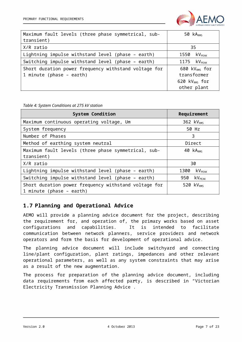
1.6 System ConditionsTable 3 and Table 4 list the power system conditions under which the primary plant and equipment to be installed as part of the Augmentation must operate satisfactorily. Further information regarding required power system conditions for the various Victorian transmission system voltages is provided in Appendix A.
Table 3: System Conditions at 500 kV station
System Condition RequirementMaximum continuous operating voltage, Um 550 kVRMS
System frequency 50 HzNumber of Phases 3Method of earthing system neutral DirectMaximum fault levels (three phase symmetrical, sub-transient) 50 kARMS
X/R ratio 35Lightning impulse withstand level (phase – earth) 1550 kVPEAK
Switching impulse withstand level (phase – earth) 1175 kVPEAK
Short duration power frequency withstand voltage for 1 minute (phase – earth) 680 kVRMS for transformer620 kVRMS for other plant
Table 4: System Conditions at 275 kV station
System Condition RequirementMaximum continuous operating voltage, Um 362 kVRMS
System frequency 50 HzNumber of Phases 3Method of earthing system neutral DirectMaximum fault levels (three phase symmetrical, sub-transient) 40 kARMS
X/R ratio 30Lightning impulse withstand level (phase – earth) 1300 kVPEAK
Switching impulse withstand level (phase – earth) 950 kVPEAK
Short duration power frequency withstand voltage for 1 minute (phase – earth) 520 kVRMS
1.7 Planning and Operational AdviceAEMO will provide a planning advice document for the project, describing the requirement for, and operation of, the primary works based on asset configurations and capabilities. It is intended to facilitate communication between network planners, service providers and network operators and form the basis for development of operational advice.
Version 2.0 4 October 2013 Page 5 of 15

PRIMARY FUNCTIONAL REQUIREMENTS
The planning advice document will include switchyard and connecting line/plant configuration, plant ratings, impedances and other relevant operational parameters, as well as any system constraints that may arise as a result of the new augmentation.
The process for preparation of the planning advice document, including data requirements from each affected party, is described in “Victorian Electricity Transmission Planning Advice”.
2 Augmentation Requirements
2.1 GeneralAll primary plant and equipment forming part of the Augmentation must be installed and commissioned to accommodate the proposed connection arrangement depicted in Attachment D.1.All primary plant and equipment must conform with all relevant Australian Standards. In the absence of an Australian Standard, the relevant International Electro-technical Committee (IEC) standards shall apply. A listing of relevant standards and guides is included in Table 11.
All installed primary plant and equipment must allow for maintenance and repair of failed components while minimising the impact on power system performance as follows:
Outage of equipment within a bay (excluding bus-side isolators and earth switches) for maintenance, repair or extension purposes must not require any connecting busbar or equipment within an adjacent bay to be taken out of service;
Outage of bus-side isolators or earth switches must not require outage of equipment beyond the adjacent busbar and bay;
Outage of equipment must not compromise the protection and control of in-service plant.
Secondary equipment and wiring must not permanently limit primary plant ratings.
2.2 Network Services
This section identifies the network services that the installed primary plant and equipment is required to provide. Table 5 provides a general description of the required services.
Table 5: Network Services
Services Works Required for Service Delivery
Shared network services associated with the new primary plant and equipment.
Provide and maintain the power transfer capability outlined Table 6.
Provide and maintain the fault withstand and switching capabilities outlined in Table 6
Provide and maintain the configuration switching capability outlined in Table 6
Provide and maintain protection, communications, monitoring and control services as detailed in the secondary works PCR documentation listed in Table 1.
2.3 Power Transfer and Switching CapabilityAttachment D.1 shows the required connection and switching arrangement for the Heywood Terminal Station. Table 6 defines the required node to node network service performance for the new connection, based on the node definitions in Attachment D.1.
Version 2.0 4 October 2013 Page 6 of 15
PRIMARY FUNCTIONAL REQUIREMENTS
Table 6: Network Service Performance Requirements
Node
Fault Withstand Capability Continuous Thermal Rating (Summer Ambient Temperature1)
kARMS
SymmetricalX/R Ratio Amps
A – C – B 50 35 6000F – E – G 50 35 6000C – D – E 50 35 4000
D – X - W 50 35 TNSP to advise2
O – V 40 30 31503
N – O – P 40 30 4500Note 1: See Section 2.6.2 for further details of the Continuous Thermal Rating Requirements.Note 2: Rating of D-X-W must not limit M3 transformer rating.Note 3: Isolator must be rated at 3150 A, link may be rated at lower value but must not limit M3 transformer rating (TNSP to advise)
2.4 Design of M3 Transformer Connection to the 500 kV Bus TieA connector is required between the proposed M3 transformer and the 500 kV Bus Tie circuit breakers (point X shown in Attachment D.1). The connector must enable the 500 kV Bus Tie to remain in service during an outage of the M3 transformer. Isolation of the M3 transformer from the 500 kV bus tie must be achieved within one hour for a planned outage and within seven hours for an unplanned outage of the M3 transformer.
2.5 Interfacing with SPI PowerNet’s Shared NetworkThe Augmentation includes connection of the 500 kV bus extensions to SPI PowerNet’s existing 500 kV buses, and connection of the Bay 3 275 kV bus extension to SPI PowerNet’s 275 kV bus extension in Bay 4 as shown in Attachment D.1.
The design of the primary plant and equipment must be co-ordinated with SPI PowerNet’s Shared Network Interface design.
2.6 Primary Plant
2.6.1 Equipment RatingsAll new primary plant and equipment must be rated for operation at all times under the power system conditions listed in Table 3 to provide the required performance specified in Table 6 and ratings listed in Table 7 to Table 10.
Version 2.0 4 October 2013 Page 7 of 15

PRIMARY FUNCTIONAL REQUIREMENTS
Table 7: New Primary Plant Ratings Requirements (Switchgear) for 500 kV station
Parameter UnitsEquipment
Circuit Breaker1,2,5
Isolator 3/ Connector
Earth Switch 3,4
Maximum continuous operating voltage kV 550 550 550
Lightning impulse withstand level (LIWL) kVPEAK 1550 1550 1550
Switching impulse withstand level (SIWL) kVPEAK 1175 1175 1175
Continuous thermal rating(At 40ºC ambient) A 4000 4000 N/A
Symmetric Fault withstand capability
(1 second duration)kARMS 50 50 50
Fault interrupt capability kARMS 50 N/A N/A
Fault make capability kAPEAK 135 N/A N/AX/R Ratio - 35 35 35
Note 1: Circuit breakers must be capable of withstanding the Transient Recovery Voltages (TRVs) that may be experienced on switching, or alternatively install additional primary plant to limit the TRV rate of rise to an acceptable level.
Note 2: To be specified where required for specific projects. Circuit breaker making and breaking duty, including TRV withstand, also needs to accommodate any possible requirement for the future connection of underground cable circuits (i.e. to account for specific capacitive charging currents).
Note 3: Isolators shall be motorised as necessary to enable remote operation.Note 4: Earth switches shall be capable of withstanding electromagnetic and electrostatic induced currents and voltages under all
operating and system conditions <These system conditions are project specific and should be specified taking into account foreseeable developments within the local network.>
Note 5: Point-on-wave switching, fault clearing times and auto-reclose facilities are to be as specified in the PCR.
Table 8: New Primary Plant Rating Requirements (Instrumentation) for 500 kV station
Parameter UnitsEquipment
Current Transformer 1 Voltage TransformerMaximum continuous operating
voltage kV 550 550
Lightning impulse withstand level (LIWL) kVPEAK 1550 1550
Switching impulse withstand level (SIWL) kVPEAK 1175 1175
Continuous thermal rating(At 40ºC ambient) A 4000 N/A
Symmetric Fault withstand capability (1 second duration) kARMS 50 N/A
Rated X/R ratio - 35 N/A
Accuracy -
Metering: ±0.2%Protection: saturation
characteristics shall be suitable for requirements of
protection scheme
Metering: ±0.2%Protection: ±1.0%
Class - Protection / Metering Protection / MeteringNote 1: Where required to interface with existing current transformers, new equipment performance must be the equivalent of the
existing equipment.
Version 2.0 4 October 2013 Page 8 of 15
PRIMARY FUNCTIONAL REQUIREMENTS
Table 9: New Primary Plant Ratings Requirements (Switchgear) for 275 kV Station
Parameter UnitsEquipment
Isolator 1 Earth Switch 1,2
Maximum continuous operating voltage kV 362 362
Lightning impulse withstand level (LIWL) kVPEAK 1300 1300
Switching impulse withstand level (SIWL) kVPEAK 950 950
Continuous thermal rating(At 40ºC ambient) A 3150 N/A
Symmetric Fault withstand capability
(1 second duration)kARMS 40 40
Fault interrupt capability kARMS N/A N/A
Fault make capability kAPEAK N/A N/AX/R Ratio - 30 30
Note 1: Isolators shall be motorised as necessary to enable remote operation.Note 2: Earth switches shall be capable of withstanding electromagnetic and electrostatic induced currents and voltages under
all operating and system conditions <These system conditions are project specific and should be specified taking into account foreseeable developments within the local network.>
Table 10: New Primary Plant Rating Requirements (Instrumentation) for 275 kV Station
Parameter UnitsEquipment
Current Transformer 1 Voltage TransformerMaximum continuous operating
voltage kV 362 362
Lightning impulse withstand level (LIWL) kVPEAK 1300 1300
Switching impulse withstand level (SIWL) kVPEAK 950 950
Continuous thermal rating(At 40ºC ambient) A 3150 N/A
Symmetric Fault withstand capability (1 second duration) kARMS 40 N/A
Rated X/R ratio - 30 N/A
Accuracy -
Saturation characteristics shall be suitable for
requirements of protection scheme.±0.2%
±1.0%
Class - Protection ProtectionNote 1: Where required to interface with existing current transformers, new equipment performance must be the equivalent of the
existing equipment.
Version 2.0 4 October 2013 Page 9 of 15

PRIMARY FUNCTIONAL REQUIREMENTS
2.6.2 Service Environmental ConditionsAll new primary plant and equipment must:
be designed to operate from -5°C up to +40°C (shade ambient temperature) and under all other environmental conditions specified in Appendix A. Where standard seasonal ratings are specified, the winter rating shall be 5°C (shade ambient temperature); and
operate reliably and otherwise satisfactorily up to an ambient temperature of 50°C.
All insulation of primary plant, must be designed in accordance with Australian Standards to cater for Level III (Heavy) pollution, as defined in AS 4436.
2.6.3 Interplant Connections
The minimum rating of inter-plant connections must be consistent with both the expected power system conditions shown in Table 3 and the requirements detailed in Table 6 of the plant being connected.
Inter-plant connections must be designed to withstand the short circuit forces arising under maximum fault level conditions.
2.6.4 Power TransformersThe Augmentation includes installation of the M3 transformer for connection between the shared network 500 kV and 275 kV buses. The M3 transformer requirements are included in Appendix B.
2.7 EarthingTNSP must design and install an earthing system extension to mitigate unsafe step, touch or transfer potential from arising at any location either within or external to HYTS as a result of 500 kV and 275 kV fault levels being 15 kARMS and 20 kARMS at the respective yards, in accordance with all relevant Australian and International Standards and guides. If the existing earthing system’s rating is higher than these ratings, the earthing system extension must match the existing earthing system rating.
The earthing system extension shall be normally tied to the existing HYTS earthing system. However, facilities must be provided to allow separation for the purposes of testing.
The design of the earthing system extension must account for possible future development (see Section 2.10.4). The earthing system must be able to mitigate unsafe step or touch potentials from arising anywhere as a result of the following:
A 500 kV fault level of up to 50 kARMS through extension and not replacement of the earthing system and an X/R ratio of 35; and
A 275 kV fault level of up to 40 kARMS through extension and not replacement of the earthing system and an X/R ratio of 30.
The earthing system extension (both present and future) must be capable of carrying a fault current of 50 kARMS at 500 kV and 40 kARMS at 275 kV for a period not less than the maximum backup protection clearance time without damage.
SPI PowerNet is responsible for the earthing system falling outside of the Augmentation requirements. Step and touch potentials must be safe for all shared transmission network assets outside the Augmentation site.
Version 2.0 4 October 2013 Page 10 of 15

PRIMARY FUNCTIONAL REQUIREMENTS
2.8 Electric and Magnetic Field LevelsElectric and magnetic field levels must always allow safe access and working conditions and comply with the maximum allowable levels specified by the NHMRC in the ‘Australian Exposure Interim Guidelines’ and as published by ARPANSA (see Table 2).
The overall design must adopt an approach of "prudent avoidance" to minimise EMF throughout the HYTS.
2.9 Station Auxiliary SuppliesDuplicate AC station supplies and DC battery supplies must be made available on site as per the PCRs noted in Table 1.
2.10 Station Layout
2.10.1 Site LayoutThe primary plant and equipment layout must be designed and constructed to facilitate possible future development (see Section 2.10.4).
2.10.2 Control BuildingsAll control, protection and other auxiliary equipment is to be installed in the existing building, if possible Terms of access to the existing control building must be negotiated with SPI PowerNet. If a new building is required it must be located within the HYTS so as to allow it to be extended to accommodate the possible future development (see Section 2.10.4). Buildings must comply with the requirements of the Building Code of Australia (BCA) and with the relevant requirements of AS 2067.
At present, the BCA specifies certain requirements for electrical substations and similar installations (i.e. clause C2.13 of Volume 1), but does not allocate an unambiguous classification to stand-alone infrastructure buildings, such as electricity substations. The requirements for BCA Class 8 buildings may be used as a basic guide for the design of these buildings.
Buildings and all associated structures must be designed for an Importance Level of 4 – “Building and Structures essential to Post-Disaster Function” in accordance with the BCA, Section B – Part B1 – Structural Provisions. The design life of control buildings must be 50 years.
Adequate systems and structures are required to protect SPI PowerNet owned assets from possible Augmentation hazards, including transformer fire detection and suppression, and the containment of oil from transformer leakage or rupture.
2.10.3 Protection from DamageIn line with good electricity industry practice, reasonable isolation and physical protection of all primary plant and equipment will be required to reduce the risk of damage caused by any failure.
2.10.4 Future ConsiderationsThe design of the primary works must provide for the possible future development at the site shown in Figure 1.
Version 2.0 4 October 2013 Page 11 of 15

PRIMARY FUNCTIONAL REQUIREMENTS
Figure 1: Possible Future Development
2.11 Standards and CodesThe primary plant and equipment shall be designed, manufactured and tested in accordance with the requirements of all Regulatory Instruments and the latest revision of all relevant Australian/IEC Standards and Codes of Practice, in particular those listed in Table 11.
Where there is any inconsistency between this document and any of the standards referred to in Table 11, this document will prevail.
Version 2.0 4 October 2013 Page 12 of 15

PRIMARY FUNCTIONAL REQUIREMENTS
Table 11: Codes, Guides and Standards
Standard TitleNER National Electricity Rules Version 54
AS 1000 The International System of Units (SI) and its applicationAS 1170 Structural design actionsAS 1214 Hot-dip galvanised coatings on threaded fastenersAS 1275 Metric screw threads for fasteners;
AS 1307-2 Surge arresters Part 2: Metal-oxide surge arresters without gaps for a.c. systemsAS 1319 Safety signs for the occupational environmentAS 1627 Metal finishing – Preparation and pre-treatment of surfaces;AS 1824 Insulation coordinationAS 1767 Insulating liquidsAS 1891 Industrial fall-arrest systems and devicesAS 1931 High Voltage test techniquesAS 2067 Substations and high voltage installations exceeding 1000V AC
AS 2312 Guide to the protection of iron and steel against atmospheric corrosion by the use of protective coatings
AS 2374 series Power transformersAS/NZS 2650 Common specifications for high voltage switchgear and controlgear standards
AS 3000 Electrical Installations (AS/NZS Wiring rules)AS 3008.1.1 Electrical installations – Selection of Cables
AS/NZS 3100 Approval and test specification— General requirements for electrical equipment
AS 4398 Insulators – Ceramic or glass – Station post for indoor and outdoor use – Voltages greater than 1000VAC
AS 4436 Guide for the selection of insulators in respect of polluted conditions.AS 4680 Hot-dip galvanised (zinc) coatings on fabricated ferrous articles
AS 60044 Instrument transformersAS 60076 Power transformers
AS 60214 series Tap changersAS 60270 High voltage test techniques - Partial discharge measurementsAS 60137 Insulated bushings for alternating voltages above 1000 VIEC 60376 Specification and acceptance of new sulphur hexafluoride (SF6)AS 60529 Degrees of protection provided by enclosures (IP Code)
AS 62271 High Voltage AC switchgear & controlgear – Circuit breakers for rated values above 1000V
AS 62271.102 High voltage switchgear and controlgear – Alternating current disconnectors and earthing switches
AS 62271.301 High voltage switchgear and controlgear Part 301: Dimensional standardization of terminals
ENA EG1 Electricity Networks Association Substation Earthing GuideIEEE 80 Guide for Safety in AC Substation Grounding
Version 2.0 4 October 2013 Page 13 of 15

PRIMARY FUNCTIONAL REQUIREMENTS
Appendix A: Environmental ConditionsThe Shared Transmission Network has the following environmental requirements:
Table A 1: Environmental
Factor Source of Information Unit Service Condition
Maximum Ambient
Temperature SPI PowerNet /Bureau of Meteorology
ºC 50ºC (1,2)
Minimum Temperature ºC -10ºC
Maximum Rate of Change of
TemperatureAS 2650 ºC Fluctuations of up to 20ºC within a period of 20
minutes
Maximum solar radiation AS 2650 kW/m2 1.1 kW/m2
Altitude AS 2650 M <1000 M
Pollution AS 4436
The minimum requirement is Level III ‘Heavy’ except in locations such as heavy industrial or coastal areas where the minimum requirement is Level IV ‘Very Heavy’
Ice loading AS 2650 mm Ice loading does not exceed 1mmMaximum wind
velocity AS 2650 km/hr Steady 110 km/hr, in gusts 160 km/hr
Condensation, precipitation,
including ice and snow
AS 2650 Account needs to be taken
Average annual relative humidity
SPI PowerNet /Bureau of Meteorology % 80 %
Ground settlement SPI PowerNet Structures and connections shall allow for
ground settlementNote 1: All plant must operate reliably and otherwise satisfactorily up to a maximum ambient temperature of 50°C. As
part of any proposed design, AEMO shall be informed of the ambient temperature rating performance and any expected rating reduction over the range from 40°C to 50°C with information provided in increments of 1°C. AEMO may accept the proposed ambient temperature rating performance if it is appropriate or, if necessary, require the specification of higher-rated equipment.
Note 2: It is important to ensure that solid state devices that may be incorporated into outdoor equipment and the cooling systems for equipment such as SVC's do not constrain operation of the equipment at the temperatures specified, even if there may be some de-rating of the primary equipment. For example in an SVC, if the ambient temperature gets too high the SVC may be tripped due to the temperature limitation of the thyristors.
Version 2.0 4 October 2013 Page 14 of 15

PRIMARY FUNCTIONAL REQUIREMENTS
Appendix B: Power Transformers The M3 transformer must comply with the specifications listed Table B1.
Table B1: Power Transformer Specifications
Transformer Parameter Value
Rated frequency 50 Hz
HV-MV Rating at 40°C ambient temperature
Continuous 270 MVA (ONAN)370 MVA (ODAN)
90 minutes short term 380 MVA60 minutes short term 440 MVA30 minutes short term 525 MVA
HV-MV Rating at 50°C ambient temperatureContinuous To be advised by TNSP
2 hour short term To be advised by TNSPHalf hour short term To be advised by TNSP
LV Rating To be advised by TNSP as required to meet fault withstand and auxiliary load requirements.
Configuration 3 phase Auto transformer with a tertiary windingWinding connection YNa0d1
Nominal transformation ratio 500 / 275 / 22 kVTap control OLTC
Tapped winding Series winding [HV]Principal tap ratio 500 / 275 kV
Tap step size 1.25% or 6.25 kV
Tapping range
Range +5% to -15%Principal Tap [5] 500 kV
Max Voltage Tap [1] 525 kVMin Voltage Tap [17] 425 kV
Minimum EHV Winding continuous voltage withstand
Tap 1 – Tap 7 = 550kVTap 8 – Tap 17 = Tap Voltage x 1.14
HV-MV positive and zero sequence impedance over tapping range
Minimum 6.4% on 300 MVA baseMaximum 6.6% on 300 MVA
Preferred 6.5% at Principal Tap [5]Fault current carrying capability and duration 500 kV system: 50 kA for 1 second
Earthing of transformer neutral DirectMaximum no load loss To be advised by TNSP
Maximum on load loss (370 MVA loading) To be advised by TNSPSwitching Impulse Withstand Level
(phase – earth)(phase – phase)
1175 kVpk2035 kVpk
Lightning Impulse Withstand Level(phase – earth)
HV - 1550 kVpkMV - 1050 kVpkLV - 150 kVpk
Power Frequency Withstand Level(phase – earth for 1 minute)
HV - 680 kVrmsMV – 460 kV rmsLV – 50 kV rms
Version 2.0 4 October 2013 Page 15 of 15