· Web viewTime division multiple access (TDMA) The time division multiple access (TDMA)...
57
CS2302-Computer networks Department of CSE & IT 2012- 2013 QUESTION BANK CS2302-Computer networks UNIT I PART A 1. Compare LAN and WAN. LAN 1.Scope of Local Area Network is restricted to a small/ single building 2. LAN is owned by same organization 3. Data rate of LAN 10- 100mbps. WAN 1. scope of Wide Area Network spans over large geographical area country/ Continent. 2. a part of n/w asserts are owned or not owned 3 .Data rate of WAN is Gigabyte. 2. What is circuit switching? In a circuit-switched network, a dedicated communication path is established between two stations through the nodes of the network. That path is a connected sequence of physical links between nodes. 3. What is packet switching? In a packet-switched network, it’s not necessary to dedicate transmission capacity along a path through the network. Rather, data are sent out in a sequence of small chunks, called packets. Packet switching is mainly used in terminal-to-computer and computer-to-computer communications. 4. Define Full Duplex and simplex transmission system. With Full duplex transmission, two stations can simultaneously send and receive data from each other. This mode is known as two-way simultaneous. The signals are transmitted in only one direction. One is the sender and another is the receiver. 5. Why sliding window flow control is considered to be more efficient than stop and wait flow control? In sliding window flow control, the transmission link is treated as a pipeline that may be filled with frames in transit. But with stop-and-wait flow control only one frame may be in the pipe at a time. 6. Differentiate between lost frame and damaged frame? What is the difference between stop and wait and sliding window protocol? Lost frame is the frame that fails to arrive at the other side. The damaged frame is a recognizable frame does arrive, but some of the bits are in error. In stop and wait protocol, we can send one frame at a time where as in sliding window protocol we can send multiple frames at a time. 7. Define piggybacking. 1
Transcript of · Web viewTime division multiple access (TDMA) The time division multiple access (TDMA)...

CS2302-Computer networks Department of CSE & IT 2012-2013
QUESTION BANKCS2302-Computer networks
UNIT I PART A
1. Compare LAN and WAN. LAN1.Scope of Local Area Network is restricted to a small/ single building
2. LAN is owned by same organization
3. Data rate of LAN 10-100mbps.
WAN1. scope of Wide Area Network spans
over large geographical area country/ Continent.
2. a part of n/w asserts are owned or not owned
3 .Data rate of WAN is Gigabyte.2. What is circuit switching?
In a circuit-switched network, a dedicated communication path is established between two stations through the nodes of the network. That path is a connected sequence of physical links between nodes.
3. What is packet switching?In a packet-switched network, it’s not necessary to dedicate transmission capacity along a path through the network. Rather, data are sent out in a sequence of small chunks, called packets. Packet switching is mainly used in terminal-to-computer and computer-to-computer communications.
4. Define Full Duplex and simplex transmission system.With Full duplex transmission, two stations can simultaneously send and receive data from each other. This mode is known as two-way simultaneous. The signals are transmitted in only one direction. One is the sender and another is the receiver.
5. Why sliding window flow control is considered to be more efficient than stop and wait flow control?In sliding window flow control, the transmission link is treated as a pipeline that may be filled with frames in transit. But with stop-and-wait flow control only one frame may be in the pipe at a time.
6. Differentiate between lost frame and damaged frame? What is the difference between stop and wait and sliding window protocol?Lost frame is the frame that fails to arrive at the other side. The damaged frame is a recognizable frame does arrive, but some of the bits are in error. In stop and wait protocol, we can send one frame at a time where as in sliding window protocol we can send multiple frames at a time.
7. Define piggybacking.The technique of temporarily delaying outgoing acknowledgment so that they can be hooked onto the next outgoing data frame is widely known as piggybacking.
8. What is OSI? Define HDLC.OSI is Open Systems Interconnection and is developed by the International Organization for Standardization (ISO).
HDLC stands for High Level Data Link Control. It has three stations, two links, and three types of data transfer.9. What is a protocol? What are the key elements of a protocol?
Protocol is used for communications between entities in a system and must speak the same language. Protocol is the set of rules governing the exchange of data between 2 entities. It defines what is communicated, how it is communicated, when it is communicated
Key elements of Protocol:Syntax – It refers to the structure or format of data meaning the order in which they are presented.Semantics – It refers to the meaning of each section of bit. How to do interpretation.Timing – When data should be sent and how fast they can be sent.
10. What are the uses of transport layer? Reliable data exchange Independent of network being used Independent of application
11. What is protocol data unit (PDU)?
1

CS2302-Computer networks Department of CSE & IT 2012-2013
At each layer, protocols are used to communicate and Control information is added to user data at each layer. Transport layer may fragment user data. Each fragment has a transport header added and header consists of Destination SAP, Sequence number and Error detection code.
12. What are the uses of internet layer in TCP/IP? Systems may be attached to different networks Routing functions across multiple networks Implemented in end systems and routers
13. What is a layered Network Architecture? A layer is created when a different level of abstraction occurs at protocol. Each layer should perform a well
defined function. Function of each layer should be chosen using internationality standardized protocols. Boundaries between
should be chosen to minimize information flow across the interfaces. A set of layers and protocol is called network architecture. A list of protocols used by a system is called
protocol stack.14.Compare OSI and TCP.
Open Source Interconnection Transmission Contrl Protocol It distinguishes between It does not distinguish between
service,Interface,protocol service, interface, protocol Protocols are well hidden Protocols are not just hidden Dejure. Standard Fit Model Defacto standard Fit protocol then
then protocol model In transport layer only connection In Transport layer choice is for
Oriented services are available Connection oriented/connection less. It contains 7 layers It contains 5 layers15. How do layers of the internet model correlate to the layers of the OSI model?
OSI TCP/IPPhysical Layer Physical Layer
Data Link Layer Network Access LayerNetwork Layer IP LayerTransport Layer TCP LayerSession Layer Application LayerPresentation Layer
Application Layer16. What is the use of data link layer in OSI?
Frame synchronization: Data is divided by data link layer as frames ,a manageable unit. Flow Control: Sending station does not overwhelm receiving station. Error Control: Any error in bits must be detected and corrected using some mechanism. Addressing: Two stations in a multi point that involved in transmission must be specified using physical
address Access Control: When two or more devices are connected to the same link, Access control mechanism is
needed to determine which device has control over the link at any given time. 17. Why is flow control and error control duplicated in different layers?
Like the data link layer, the transport layer is responsible for flow and error control . Flow control and error control at data link layer is node-to-node level. But at transport layer, flow control and error control is performed end-end rather than across a single link.
18. List the key ingredients of technology that determines nature of a LAN. List the common topologies available for LAN.
Topology, Transmission medium and Medium access control technique are the technology that determines nature of a LAN. Star Topology, Ring Topology Bus Topology and Tree Topology are the topologies available for LAN.
2

CS2302-Computer networks Department of CSE & IT 2012-2013
19. What are the functions of physical layer and presentation layer?Encoding/ decoding of signals, preamble generation/removal (for synchronization) and Bit transmission/ reception
are the functions of physical layer. Translation, Encryption / Decryption, Authentication and Compression are the functions of presentation layer.20. What do you mean by Flow Control? (Nov. 2011)
Flow control is a technique for assuring that a transmitting entity does not overwhelm a receiving entity with data. Flow control—a feedback mechanism by which the receiver is able to throttle the sender. Such a mechanism is used to keep the sender from overrunning the receiver, i.e., from transmitting more data than the receiver is able to process
21. Define error detection and correction. (Nov. 2011)Error detection: Sender transmits every data unit twice. Receiver performs bit-by-bit comparison between that two versions of data. Any mismatch would indicate an error, which needs error correction.
22. What are the functions of Application Layer? (May 2011) It enables the user (human/software) to access the network. It provides user interfaces and support for services such
as electronic mail, remote file access and transfer, shared database management and other types of distributed information services. Services provided by the application layer are Network Virtual terminal, File transfer, access and management. Mail services, Directory services. 23.Define bit stuffing. (May 2011)
HDLC denotes both the beginning and the end of a frame with the distinguished bit sequence 01111110. This sequence might appear anywhere in the body of the frame, it can be avoided by bit stuffing. On the sending side, any time five consecutive 1’s have been transmitted from the body of the message (i.e., excluding when the sender is trying to transmit the distinguished 01111110 sequence), the sender inserts a 0 before transmitting the next bit.
24. What are the two types of line configuration? (Nov. 2010) Point to point line configuration and multipoint line configuration. Point to point:
It provides a dedicated link between 2 devices. Entire capacity of the link is reserved for transmission between 3 devices only Eg: connection between remote control and TV’s control system
Multipoint: Also called as multi drop connection Here the channel capacity is shared If many devices share the link simultaneously it is called spatially shared connection25. What do you mean by error control? (Nov. 2010)
Error control refers to mechanism to detect and correct errors that occur in the transmission of frames.
PART-B1. Explain in detail the error detection. (Nov. 2010)
Error Detection- Sender transmits every data unit twice. Receiver performs bit-by-bit comparison between that two versions of data. Any mismatch would indicate an error, which needs error correction. Advantage is it is very accurate. Disadvantage is time consuming.Instead of repeating the entire data stream, a shorter group of bits may be appended to the end of each unit called as “redundancy” because the extra bits are redundant to the information. Redundant information will be discarded as soon as the accuracy of the information has been determined
Types of Redundancy Checks• Parity Check
– Simple Parity Check– Two Dimensional Parity Check / Longitudinal Redundancy Check (LRC)
• Cyclic Redundancy Check (CRC)• Check Sum
Simple Parity Check• A redundant bit called “Parity Bit” is added to every data unit• Even Parity : total number of 1’s in the data unit becomes even
3

CS2302-Computer networks Department of CSE & IT 2012-2013
• Odd Parity : total number of 1’s in the data unit becomes oddError Detection- 2D/LRC
• Adds an additional character (instead of a bit)• A block of bits is organized in a table• The Parity Bit for each data unit is calculated• Then Parity Bit for each column is calculated• Parity Bits are attached to the data unit
Error Detection- CRC• Powerful error detection scheme• Rather than addition, binary division is used• A sequence of redundant bits, called “CRC” or “CRC remainder” is appended to the data unit, so that the resulting
data unit becomes divisible by a predetermined binary number• At the receiver side, the incoming data unit is divided by the same predetermined number.• If there is no remainder, the data unit is accepted• If there is a remainder, the receiver indicates that the data unit has been damaged during transmission
4

CS2302-Computer networks Department of CSE & IT 2012-2013
Error Detection- Check Sum• The Check Sum generator subdivides the data unit into equal segments of “n” bits (usually 16)• These segments are added using one’s complement arithmetic in such a way that the total is also “n” bits long • Total is complemented and appended to the end of the original data unit as redundancy bits, called the check sum
field• The sender follows these steps:
• The data unit is divided into “k” sections, each of “n” bits• All sections are added using one’s complement to get the sum• The sum is complemented and becomes the checksum.• The checksum is appended and sent with the data.
• The receiver follows these steps:• The unit is divided into “k” sections, each of “n” bits• All sections are added using one’s complement to get the sum.• The sum is complemented.• If the result is zero, the data are accepted; otherwise, rejected
5

CS2302-Computer networks Department of CSE & IT 2012-2013
Data:10101001 00111001
Computing Checksum: 10101001 00111001---------------
Sum 11100010CheckSum 00011101Data Sent :
10101001 00111001 00011101Receiver Side:
10101001 00111001 00011101 ---------------
Sum 11111111Complement 00000000
2. Explain about internet architecture. The Internet architecture, also called the TCP/IP architecture after its two main protocols, is depicted in Fig.1.
An alternative representation is given in Fig.2.
Fig.1 Internet protocol graph. 6

CS2302-Computer networks Department of CSE & IT 2012-2013
Fig2. Alternative view of the Internet architecture.At the lowest level are a wide variety of network protocols, denoted NET1, NET2, and so on.The Internet Protocol (IP) supports the interconnection of multiple networking technologies into a single, logical internetworkThe third layer contains two main protocols: the Transmission Control Protocol (TCP) and the User Datagram Protocol (UDP). TCP and UDP provide alternative logical channels to application programs: TCP provides a reliable byte-stream channel, and UDP provides an unreliable datagram delivery channel.The Internet architecture has three features: 1. The application is free to bypass the defined transport layers and to directly use IP or one of the underlying networks. 2. IP serves as the focal point for the architecture—it defines a common method for exchanging packets among a wide collection of networks. Above IP can be arbitrarily many transport protocols, each offering a different channel abstraction to application programs.
Below IP, the architecture allows for arbitrarily many different network technologies, ranging from Ethernet to FDDI to ATM to single point-to-point links.3. The existence of working implementations is required for standards to be adopted by the IETF.
3. Discuss in detail about the layers OSI model. (Nov. 2010, Nov. 2011)Purpose of the reference model was to provide a framework for the development of protocols
Fig.1 OSI model layersPhysical Layer
It coordinates the functions required to transmit a bit stream over a physical medium. It deals with the mechanical and electrical specifications of the interface and transmission media.
7

CS2302-Computer networks Department of CSE & IT 2012-2013
Mechanical: cable, plugs, pins... Electrical/optical: modulation, signal strength, voltage levels, bit times.
It also defines the procedures and functions that physical devices and interfaces have to perform for transmission to occur.
Major responsibilities of Physical layer arePhysical characteristics of interfaces and media: It defines the characteristics of the interface between the devices and the transmission media. Also defines the type of transmission medium.Representation of bits: To transmit the bits, it must be encoded into electrical or optical signals. It defines the type of representation how 0s and 1s are changed to signals.Data rate: The number of bits sent each second is also defined by the physical layer.Synchronization of bits: Sender and the receiver must be synchronized at the bit level .i.e the sender and the receiver clocks must be synchronized.
Fig.2 Information flows from top to bottom at the sender and bottom to top at the receiver.Data link layerThe data link layer is responsible for hop-to-hop (node-to-node) delivery. It transforms the physical layer a raw transmission facility to a reliable link. It makes physical layer appear error free to the network layer. The duties of the data link layer are
Framing: The data link layer divides the stream of bits received from the network layer into manageable data units called frames.
Physical Addressing: If the frames are to be distributed to different systems on the network the data link layer adds a header to the frame to define the receiver or sender of the frame. If the frame is intended for a system located outside the sender’s network then the receiver address is the address of the connecting device that connects the network to the next one.
Flow Control: If the rate at which the data absorbed by the receiver is less than the rate produced in the sender, the data link layer imposes a flow control mechanism to overwhelming the receiver.
Error control: Reliability is added to the physical layer by data link layer to detect and retransmit loss or damaged frames and also to prevent duplication of frames. This is achieved through a trailer added to the end of the frame
Access control: When two or more devices are connected to the same link it determines which device has control over the link at any given time.
Network Layer The network layer is responsible for source-to-destination delivery of a packet across multiple networks. It ensures that each packet gets from its point of origin to its final destination .It does not recognize any relationship between those packets. It treats each one independently as though each belong to separate message.The functions of the network layer are
8

CS2302-Computer networks Department of CSE & IT 2012-2013
Logical Addressing: If a packet has to cross the network boundary then the header contains information of the logical addresses of the sender and the receiver.
Networking: When independent networks or links are connected to create an internetwork or a large network the connective devices route the packet to the final destination.
Transport LayerThe network layer is responsible for process-to-process delivery that is source to destination delivery of the entire message. The responsibilities of Transport layer are
Service-point (port) addressing: Computers run several programs at the same time. source-to-destination delivery means delivery from a specific process on one computer to a specific process on the other. The transport layer header therefore includes a type of address called a service – point address.
Segmentation and reassembly A message is divided into segments and each segment contains a sequence number. These numbers enable the Transport layer to reassemble the message correctly upon arriving at the destination. The packets lost in the transmission is identified and replaced.
Connection control: The transport layer can be either connectionless or connection-oriented. A connectionless transport layer treats segment as an independent packet and delivers it to the transport layer. A connection-oriented transport layer makes a connection with the transport layer at the destination machine and delivers the packets. After all the data are transferred, the connection is terminated.
Flow control: Flow control at this layer is performed end to end. Error Control: Error control is performed end to end. At the sending side, the transport layer makes sure that the
entire message arrives at the receiving transport layer with out error. Error correction is achieved through retransmission.Session Layer: Session layer is the network dialog controller. It establishes, maintains, and synchronizes the interaction between communicating systems. Specific responsibilities of the layer are
Dialog Control: Session layer allows two systems to enter in to a dialog. Communication between two processes takes place either in half-duplex or full-duplex. Example: the dialog between a terminal connected to a mainframe. Can be half-duplex.
Synchronization. The session layer allows a process to add checkpoints into a stream of data. Example If a system is sending a file of 2000 pages, check points may be inserted after every 100 pages to ensure that each 100 page unit is advised and acknowledged independently. So if a crash happens during the transmission of page 523, retransmission begins at page 501, pages 1 to 500 need not be retransmitted.Presentation layer: It is concerned with the syntax and semantics of the information exchanged between two systems. Responsibilities of the presentation layer are
Translation .The processes in two systems are usually exchanging information in the form of character strings, numbers, and so on. Since different computers use different encoding systems, the presentation layer is responsible for interoperability between these different encoding methods. At the sender, the presentation layer changes the information from its sender-dependent format into a common format. The presentation layer at the receiving machine changes the common format into its receiver dependent format.
Encryption. The sender transforms the original information from to another form and sends the resulting message over the entire network. Decryption reverses the original process to transform the message back to its original form.
Compression. It reduces the number of bits to be transmitted. It is important in the transmission of text, audio and video.Application Layer: It enables the user (human/software) to access the network. It provides user interfaces and support for services such as electronic mail, remote file access and transfer, shared database management and other types of distributed information services. Services provided by the application layer are
Network Virtual terminal: A network virtual terminal is a software version of a physical terminal and allows a user to log on to a remote host.
File transfer, access and management: This application allows a user to access files in a remote computer, to retrieve files from a remote computer and to manage or control files in a remote computer.
9

CS2302-Computer networks Department of CSE & IT 2012-2013
Mail services: This application provides the basis for e-mail forwarding and storage. Directory services: It provides distributed database sources and access for global information about various objects
and services.
4. Explain briefly about various physical links available.Physical links: Network connectivity occurs at many different levels. At the lowest level, a network can consist of
two or more computers directly connected by some physical medium, such as a coaxial cable or an optical fiber. We call such a physical medium a link.
Figure A Direct links: (a) point-to-point; (b) multiple-access.In Figure A, physical links are sometimes limited to a pair of nodes (such a link is said to be point-to-point), while more than two nodes may share a single physical link (such a link is said to be multiple access). Whether a given link supports point-to-point or multiple access connectivity depends on how the node is attached to the link.Explain about Leased Lines, Last-Mile Links and Wireless Links.
Channel access on linksThe network as providing logical channels over which application-level processes can communicate with each other; each channel provides the set of services required by that application. A channel Is connecting one process to another. Figure B shows a pair of application-level processes communicating over a logical channel that is, in turn, implemented on top of a cloud that connects a set of hosts. The channel is like a pipe connecting two applications, so that a sending application can put data in one end and expect that data to be delivered by the network to the application at the other end of the pipe.Applications supported on any network is a file access program like FTP (File Transfer Protocol) or NFS (Network File System).The process that requests access to the file is called the client, and the process that supports access to the file is called the server. The client sends a large message containing the data to be written to the server, and the server responds with a small message confirming that the write to disk has taken place.A client process makes a request, and a server process responds by returning the requested data. The following two types of channels: request/reply channels and message stream channels. The request/reply channel would be used by the file transfer and digital library applications.Every message sent by one side is received by the other side and that only one copy of each message is delivered. The request/reply channel might also protect the privacy and integrity of the data that flows over it, so that unauthorized parties cannot read or modify the data being exchanged between the client and server processes.
10

CS2302-Computer networks Department of CSE & IT 2012-2013
Figure B Processes communicating over an abstract channel.The message stream channel could be used by both the video-on-demand and video conferencing applications, provided it is parameterized to support both one-way and two-way traffic and to support different delay properties. The message stream channel might not need to guarantee that all messages are delivered, since a video application can operate adequately even if some frames are not received.Those messages that are delivered arrive in the same order in which they were sent, to avoid displaying frames out of sequence. The message stream channel might want to ensure the privacy and integrity of the video data. The message stream channel might need to support multicast, so that multiple parties can participate in the teleconference or view the video.
5. Explain Sliding window flow control and stop and wait flow control in detail.
11

CS2302-Computer networks Department of CSE & IT 2012-2013
12

CS2302-Computer networks Department of CSE & IT 2012-2013
6. Discuss in detail about the Byte- oriented Protocols (PPP), Bit –oriented Protocols(HDLC) and SONET. (apr. 2011).
Point-to-Point Protocol (PPP)The more recent Point-to-Point Protocol (PPP). The format of PPP frame is
Fig: PPP Frame Format The Flag field has 01111110 as starting sequence. The Address and Control fields usually contain default values The Protocol field is used for demultiplexing. The frame payload size can he negotiated, but it is 1500 bytes by default. The PPP frame format is unusual in that several of the field sizes are negotiated rather than fixed. Negotiation is conducted by a protocol called LCP (Link Control Protocol). LCP sends control messages encapsulated in PPP frames— such messages are denoted by an LCP identifier in the PPP Protocol.Bit-Oriented Protocols (HDLC)In this, frames are viewed as collection of bits. High level data link protocol is used. The format is
Fig: HDLC Frame Format HDLC denotes both the beginning and the end of a frame with the distinguished bit sequence 01111110. This sequence might appear anywhere in the body of the frame, it can be avoided by bit stuffing. On the sending side, any time five consecutive 1’s have been transmitted from the body of the message (i.e., excluding when the sender is trying to transmit the distinguished 01111110 sequence), the sender inserts a 0 before transmitting the next bit. On the receiving side, five consecutive 1’s arrived, the receiver makes its decision based on the next bit it sees (i.e., the bit following the five is). If the next bit is a 0, it must have been stuffed, and so the receiver removes it. If the next bit is a 1, then one of two things is true, either this is the end-of-frame marker or an error has been introduced into the bit stream. By looking at the next bit, the receiver can distinguish between these two cases: If it sees a 0 (i.e., the last eight bits it has looked at are 01111110), then it is the end-of- frame marker. If it sees a 1 (i.e., the last eight bits it has looked at are 01111111), then there must have been an error and the whole frame is discarded.
Clock Based Framing(SONET)Synchronous optical network is used for digital transmission over optical n/w. It is mainly applied for long distance transmissions. * Sonet addresses both framing & encoding issues. Also several low speed links can be multiplexed on to 1 high speed link. * A Sonet frame has spl info (overhead info) that tells receiver where frame starts and ends. No bit stuffing is used here and frame’s length does not depend on data.
STS-1 Frame9 rows of 90 byte each
13

CS2302-Computer networks Department of CSE & IT 2012-2013
First 3 byte for overhead rest contains data of which 2 bytes tells start and end of each frameIf start and end patterns are repeated in data part, rcvr identifies it as, it looks for spl bit pattern consistently,
hoping to see it appearing once every 810 bytes, since each frame is 9 x 90 = 810 bytes. Overhead bytes of Sonet are encoded using NRZ encoding where highs are 1 and lows are 0. If continuous 1s or 0s are present in data, receiver may misinterpret the sequence. Hence a bit sequence of length 127 bits are xored with data to produce enough transitions for the receiver to correctly synchronize with sender. Such a method is called scrambling.
Multiplexing Support in Sonet • A single Sonet frame can contain sub frames for multiple lower channels. i.e., an STS-3 frame contains 3 STS-1
frames.• Such multiplexed sonet frame’s bytes are interleaved, ensuring each STS-1 frame are evenly placed.• During multiplexing, payloads of all STS-1 frames can be linked together forming a larger payload, denoted as STS-
NC ( C- Concatenated) . An STS-3c frame differs form a STS-3 frame. Former is regarded as a single link and latter as 3 STS-1 frames.
• Another feature of sonet frames is that frame boundaries are not strictly followed. i.e., a frame may extend and float in another frames’ region. In such cases the start and end of frame could be identified by bits present in overhead.
7.With a neat diagram explain in detail about the network architecture. (Apr. 2011)When the system gets complex, the system designer introduces another level of abstraction.The challenge is to identify abstractions that simultaneously provide a service that proves useful in a large number of situations and that can be efficiently implemented in the underlying system.Abstractions naturally lead to layering, especially in network systems.we might imagine a network as having two layers of abstraction sandwiched between the application program and the underlying hardware, as illustrated in Figure 1.
Figure 1 Example of a layered network system. The layer immediately above the hardware in this case might provide host-to-host connectivity, abstracting away the fact that there may be an arbitrarily complex network topology between any two hosts.
14

CS2302-Computer networks Department of CSE & IT 2012-2013
The next layer up builds on the available host-to-host communication service and provides support for process-to-process channels.Layering provides two features.
1. It decomposes the problem of building a network into more manageable components.2. It provides a more modular design. If you decide that you want to add some new service, you may only need to
modify the functionality at one layer, reusing the functions provided at all the other layers.
Figure 2 Layered systems with alternative abstractions available at a given layer.the abstract objects that make up the layers of a network system are called protocols. That is, a protocol provides a communication service that higher-level objects use to exchange messages.Each protocol defines two different interfaces.
1. it defines a service interface to the other objects on the same computer that want to use its communication services. This service interface defines the operations that local objects can perform on the protocol. For example, a request/reply protocol would support operations by which an application can send and receive messages.
2. a protocol defines a peer interface to its counterpart (peer) on another machine. This second interface defines the form and meaning of messages exchanged between protocol peers to implement the communication service.
Fig: Service and peer interfaces.Except at the hardware level, peer to peer communication is indirect. Peer-to-peer communication is indirect—each
protocol communicates with its peer by passing messages to some lower-level protocol, which in turn delivers the message to its peer. We represent the suite of protocols that make up a network system with a protocol graph. The nodes of the graph correspond to protocols, and the edges represent a depends-on relation.
15

CS2302-Computer networks Department of CSE & IT 2012-2013
Fig: Example of a protocol graph.The protocols RRP (Request/Reply Protocol) and MSP (Message Stream Protocol) implement two different types of
process-to-process channels, and both depend on HHP (Host-to-Host Protocol), which provides a host-to-host connectivity service.
Suppose that the file access program on host 1 wants to send a message to its peer on host 2 using the communication service offered by protocol RRP. The file application asks RRP to send the message on its behalf.To communicate with its peer, RRP then invokes the services of HHP, which in turn transmits the message to its peer on the other machine.
Once the message has arrived at protocol HHP on host 2, HHP passes the message up to RRP, which in turn delivers the message to the file application. The application is said to employ the services of the protocol stack RRP/HHP.protocol specification are expressed using a combination of prose, pseudocode, state transition diagrams, pictures of packet formats, and other abstract notations.
Two or more protocol modules that do accurately implement a protocol specification are said to interoperate with each other. We can imagine many different protocols and protocol graphs that satisfy the communication requirements of a collection of applications.
For example, the file access program on host 1 wants to send a message to its peer on host 2 using the communication service offered by protocol RRP. In this case, the file application asks RRP to send the message on its behalf. To communicate with its peer, RRP then invokes the services of HHP, which in turn transmits the message to its peer on the other machine. Once the message has arrived at protocol HHP on host 2, HHP passes the message up to RRP, which in turn delivers the message to the file application. In this particular case, the application is said to employ the services of the protocol stack RRP/HHP.EncapsulationControl information must be added with the data to instruct the peer how to handle with the received message. It will be added into the header or trailer. Header - Small data structure from few bytes to few kilobytes attached to the front of message. Trailer – Information will be added at the end of the messagePayload or message body – Data send by the programIn this case data is encapsulated with new message created by protocol at each level.
16

CS2302-Computer networks Department of CSE & IT 2012-2013
Fig: High-level messages are encapsulated inside of low-level messages.In this example HHP encapsulates RRP’s message by attaching a header of its own. Then HHP sends the message to its peer over some network, and then when the message arrives at the destination host, it is processed in the opposite order.Multiplexing and De-Multiplexing
The fundamental idea of packet switching is to multiplex multiple flows of data over a single physical link. This can be achieved by adding identifier to the header message. It is known as demultiplexing or demux key. It gives the address to which it has to communicate. The messages are demultiplexed at the destination side. In some cases same demux key is used on both sides and in some cases different keys are used. RRP Is implementing a logical communication channel, with messages from two different applications multiplexed over this channel at the source host and then demultiplexed back to the appropriate application at the destination host.
The header that RRP attaches to its messages contains an identifier that records the application to which the message belongs. We call this identifier RRP’s demultiplexing key, or demux key. At the source host, RRP includes the appropriate demux key in its header. When the message is delivered to RRP on the destination host, it strips its header, examines the demux key, and demultiplexes the message to the correct application.
8. Explain various channel access techniques. In telecommunications and computer networks, a channel access method or multiple access method
allows several terminals connected to the same multi-point transmission medium to transmit over it and to share its capacity. Examples of shared physical media are wireless networks, bus networks, ring networks, hub networks and half-duplex point-to-point links. A channel-access scheme is based on a multiplexing method, that allows several data streams or signals to share the same communication channel or physical medium. Multiplexing is in this context provided by the physical layer. Multiplexing may be used in full-duplex point-to-point communication between nodes in a switched network, which should not be considered as multiple access.
A channel-access scheme is also based on a multiple access protocol and control mechanism, also known as media access control (MAC). This protocol deals with issues such as addressing, assigning multiplex channels to different users, and avoiding collisions. The MAC-layer is a sub-layer in Layer 2 (Data Link Layer) of the OSI model and a component of the Link Layer of the TCP/IP model.These are the four fundamental types of channel access schemes:1. Frequency division multiple access (FDMA)
The frequency division multiple access (FDMA) channel-access scheme is based on the frequency-division multiplex (FDM) scheme, which provides different frequency bands to different data-streams. In the FDMA case, the data streams are allocated to different users or nodes. An example of FDMA systems were the first-generation (1G) cell-phone systems. A related technique is wave-length division multiple access (WDMA), based on wavelength division multiplex (WDM), where different users get different colors in fiber-optical communication.2. Time division multiple access (TDMA)
17

CS2302-Computer networks Department of CSE & IT 2012-2013
The time division multiple access (TDMA) channel access scheme is based on the time division multiplex (TDM) scheme, which provides different time-slots to different data-streams (in the TDMA case to different transmitters) in a cyclically repetitive frame structure. For example, user 1 may use time slot 1, user 2 time slot 2, etc. until the last user. Then it starts all over again.Packet mode
Packet mode multiple-access is typically also based on time-domain multiplexing, but not in a cyclically repetitive frame structure, and therefore it is not considered as TDM or TDMA. Due to its random character it can be categorised as statistical multiplexing methods, making it possible to provide dynamic bandwidth allocation.The following are examples of packet mode channel access methods:
Contention based random multiple access methods Aloha Slotted Aloha Multiple Access with Collision Avoidance (MACA) Multiple Access with Collision Avoidance for Wireless (MACAW) Carrier sense multiple access (CSMA) Carrier sense multiple access with collision detection (CSMA/CD) - suitable for wired networks Carrier sense multiple access with collision avoidance (CSMA/CA) - suitable for wireless networks
Distributed Coordination Function (DCF) Point Coordination Function (PCF)
Carrier sense multiple access with collision avoidance and Resolution using Priorities (CSMA/CARP) Carrier Sense Multiple Access/Bitwise Arbitration (CSMA/BA) Based on constructive interference (CAN-bus)
3. Code division multiple access (CDMA)The code division multiple access (CDMA) scheme is based on spread spectrum. An example is the 3G cell phone system.4. Space division multiple access (SDMA)Duplexing methodsWhere these methods are used for dividing forward and reverse communication channels, they are known as duplexing methods, such as:
Time division duplex (TDD) Frequency division duplex (FDD)
Code Division Multiple Access: CDMAIn CDMA, one channel carries all transmissions simultaneously. CDMA uses unique spreading codes to spread the
baseband data before transmission. The signal is transmitted in a channel, which is below noise level. The receiver then uses a correlator to despread the wanted signal, which is passed through a narrow band pass filter. Unwanted signals will not be despread and will not pass through the filter. Codes take the form of a carefully designed one/zero sequence produced at a much higher rate than that of the baseband data. The rate of a spreading code is referred to as chip rate rather than bit rate.
18

CS2302-Computer networks Department of CSE & IT 2012-2013
Simple idea of communication with CDMA
One channel carries all transmissions simultaneouslyTwo properties that the assigned cods have:
If we multiply each code by another, we get 0. If we multiply each code by itself, we get number of channel
Each station wants to receive data from one of other stations multiplies the common data on the channel by the code of the sender.
9.Explain the different types of multiplexing. (nov. 2011)Multiplexing is the set of techniques that allows the simultaneous transmission of multiple signals across a single data link. The need for multiplexing in data transmission:
Whenever the transmission capacity of a medium linking two devices is greater than the transmission needs of the devices, the link can be shared. MULTIPLEXING is the set of techniques that allows simultaneous transmission of multiple signals across a single data link. As data and telecommunications usage increases traffic also increases. We can accommodate this increase by continuing to add individual lines each time a new channel is needed, or we can install a higher capacity links and use each to carry multiple signals. Signals are multiplexed using 3 basic techniques
FDM – Frequency Division Multiplexing – an analog technique, applied when the BW of a link is greater than the combined bandwidths of the signals to be transmitted.WDM – Wave Division Multiplexing – involves light signals transmitted through fiber-optic channels. TDM – Time Division Multiplexing – a digital process, applied when the data rate capacity of the transmission medium is greater than the data rate required by the sending and receiving devices. TDM is of 2 types – Synchronous and Asynchronous/statistical TDM/concentrator.The types of multiplexing:
19

CS2302-Computer networks Department of CSE & IT 2012-2013
Upward multiplexing Downward multiplexing
1. Frequency divisionWhen bandwidth (Hz) of link is greater then combined bandwidth of signals.Each sending device modulate Signals at different carrier frequency.Modulated signals are combined into a single signal.Channels are formed through which various signals travel.
Time division multiplexing• Instead of sharing portion of bandwidth as in FDM, time is shared.• Each connection occupies a portion of time in link.
10.Discuss about Error Correction.A receiver can use an error-correcting code, which automatically corrects certain errors
• Single-bit errors:– Can be detected by the addition of parity bit which helps to find “error” or “no error” which is
sufficient to detect errors– To correct errors the receiver can simply invert 0 to 1 or 1 to 0, but the problem is “locating” the
position of error– To do so requires enough redundancy bits – Condition: 2r >= m + r + 1
• Hamming Code can be applied to data units of any length and uses the relationship between data and redundancy bits
• For example: a 7-bit ASCII code requires 4 redundancy bits that can be added to the end of the data unit or mixed with the original data bits, which are placed in positions 1, 2, 4 and 8 i.e x0,x1,x2,x3 and so on.
• In the Hamming Code, each “r” bit for one combination of data bits as below:
r1: bits 1, 3, 5, 7, 9, 11r2: bits 2, 3, 6, 7, 10, 11r3: bits 4, 5, 6, 7r4: bits 8, 9, 10, 11
20

CS2302-Computer networks Department of CSE & IT 2012-2013
21

CS2302-Computer networks Department of CSE & IT 2012-2013
UNIT- IIPART A
1. List the advantages of a centralized scheme. It may afford greater control over access for priorities, overrides, and guaranteed capacity. It enables the use of relatively simple access logic at each station. It avoids problems of distributed coordination among peer entities.
2. Mention some of the physical properties of Ethernet? (may 2011)The Ethernet is a multiple-access network, meaning that a set of nodes send and receive frames over a shared link. An Ethernet is like a bus that has multiple stations plugged into it. What is CSMA/CD? (Nov. 2011)It is a protocol used to sense whether a medium is busy before transmission but it has the ability to check whether a transmission has collided with another.
3. List the rules for CSMA/CD.1. If the medium is idle, transmit; otherwise go to step 2.2. If the medium is busy, continue to listen until the channel is idle, and then transmit immediately.3. If a collision detected during transmission, transmit a brief jamming signal to all station to indicate collision has occurred and then cease transmission.4. After transmitting a jamming signal, wait for some time, then transmit again.
4. What is preamble and MAC?A 7-octet pattern of alternating 0s and 1s is used by the receiver to establish bit synchronization is called as preamble. Medium Access Control field contains any protocol control information needed for the functioning of the MAC protocol. For example, a priority level could be indicated here.
5. When a transmitting station will insert a new token on the ring?It will insert a new token when the station has completed transmission of its frame.The leading edge of the transmitted frame has returned to the station.
6. What is Early Token Release (ETR)?ETR allows a transmitting station to release a token as soon as it completes frame transmission, whether or not the frame header has returned to the station.
7. What is Frame Status (FS)?It contains the error detected (E), address recognized (A), and frame coped (F) indicators. Each indicator is represented by a symbol, which is R for “reset” or “false” and S for “set” or “true”.
8. Give the applications of wireless LANs.LAN extension, cross building interconnect, nomadic access, and advantages hoc networks.
9. What is a bridge? (Nov. 2011)Bridge is a hardware networking device used to connect two LANs. A bridge operates at data link layer of the OSI
layer. A bridge observes and forwards all frames that it receives. It does forwarding & filtering frames using LAN destination address. Bridges are used to connect LAN or WAN and works at data link layer level. Collision Probability is more.
10. What is No-transition?A station of this type is either stationary or moves only within the direct communication range of the communicating stations of a single BSS(Basic Service Set).
11. What is spanning tree routing?The spanning tree approach is a mechanism in which bridges automatically develop a routing table and update that table in response to changing topology.
12. Ethernet stipulates a minimum size of a frame. Why is it necessary?Ethernet is a networking topology developed in 1970 which is governed by the IEEE 802.3 specification. To
detect collision and to identify valid frame from garbage, valid full format should contain 64 bytes from destination address to checksum. So if the data portion is less than 46 bytes, pad field is used to fill out the frame to minimize size.
22

CS2302-Computer networks Department of CSE & IT 2012-2013
13. What is the advantage of FDDI over a basic token ring? (NOV. 2010)FDDI 802.5
No priority and reservation bits. It has priority scheme by using reservation bits.No need of converting a token to start of data frame by inverting token bits because of high data rate.
It converts a token to data frame changing token frame.
A station that transmits data frames releases a new token as soon as it completes data.
A station that data transmissions after releasing back its own transmission, release the token.
14. Give the format of Ethernet address. Preamble 64
Dest addr48
Src addr48
Type16
Body CRC32
15. What is meant by the contention period of Ethernet? How many lines are required to connect n – systems in Direct Mesh topology?
When several stations on an Ethernet have data to send, there are contention periods during which collisions happen and no data is successfully transmitted. n(n-1)/2 lines are required.
16. What does IEEE 10 Base 5 standard signify?10 represents data rate 10 Mbps.5 refers to segment length 5* 100 m that can run without repeatersBase represents Base band communication.
17. Define Repeater and Hub. Repeaters and hubs are interconnecting devices. Repeater: Repeaters extends the Ethernet segment and it repeats the signal. It does not amplify the signal. Hub: A Hub has several point to point segments coming out. It is a multi way repeater. It broadcasts any signal through all outgoing lines.
18. What is meant by Exponential back of algorithm?After first collision, each station waits either 0 or 1 slot time before trying again. If 2 stations collide and each one picks same random number 0/1. After second collision, each one picks either 0,1,2 or 3 slot at random and waits. If collision occurs again, then next time the number of slots to wait is chosen at random from 0 to [23 – 1]. This algorithm is called binary exponential “back off algorithm”.
19. Define a switch.Switches are hardware or software device capable of creating temporary connections between more devices which are not directly connected. It is a multi input/output port device. It transfers data coming from one input port to one or more output ports. This function is called as forwarding. Reliability, performance, security, and geography are the reason for using bridges in LAN.
20.Define Spanning Tree Algorithm.Bridge connects n/w and removes loop in the path using spanning tree algorithm It constructs a spanning tree of edges between hosts that maintain connectivity of the graph with no loops. It is a dynamic algorithm. The algorithm works as Frame Forwarding, Address Learning and Loop Resolution.
21. Mention the different types of bridge. What are the limitations of bridges? Simple Bridge connect 2 LAN Multi port Bridge connect more than 2 LANs Transparent Bridge it learns on its own about connected LANs.
The limitations of bridges:Scalability and Hetrogenity.
22. What are the functions of Bridges? (Nov. 2010) 1. A bridge should have enough buffer space to store the frames until it is transmitted. 2. It should be able to distinguish addresses of host on different LAN. 3. It can contain information about other bridges.
23

CS2302-Computer networks Department of CSE & IT 2012-2013
4. It should follow congestion control mechanisms to overcome congestion. 5. It works at layer 1 and layer 2 level.
23.Name any two network connecting devices? Can a bridge replace repeater for interconnecting 2 segments of a n/w? Repeater repeats the signal to the actual strength so that they can travel and works at physical layer. Repeater
operates on the physical layer level. Here collision probability is more. A bridge cannot replace repeater for interconnecting 2 segments of a network because functions of them are entirely
different.24.What are the advantages of switches? Write the frame format for FDDI.
In switches, the sending information are directly transmitted to the concern receiver.
8 8 48 48 32 8 24
Start ofControl
Dest SrcBody CRC
End ofStatus
frame addr Addr frame
25. What is Token ring? What is the use of bit stuffing?Token ring is a set of nodes are connected together in a ring. Data flow always in a particular direction around the ring. Bit stuffing is bit oriented protocol. It is used to detect the error during the transmission of the stream of bits.
PART-B1. Explain in detail about token ring and its frame format. (nov. 2011)
Token ring network (IEEE 802.5) consists of a set of nodes connected in a ring.• Data always flows in a particular direction around the ring• Each node receiving frames from its up stream neighbor and then forwarding them to its downstream
neighbor• The ring is viewed as a single shared medium• It does not behave as a collection of independent point-to-point links that just happen to be configured in a
loop
• Requires that stations take turns sending data• Token is a specially formatted three-byte frame that circulates; station wishing to transmit must first have
possession• Token passes from NIC to NIC in sequence; if station has data to send, station takes token and sends data
frame; if not, passes to neighbor• Each station receives the frame one by one and examines the destination address• If it matches, frame is copied; station checks the frame for errors; changes bits to indicate the frame was
received and copied• Packet continues around the ring and is passed back to originating station
24

CS2302-Computer networks Department of CSE & IT 2012-2013
• Once the sender receives the frame and recognizes its address in the sender field, it examines the address-recognized bits
• If they are set, it knows the frame was received and copied• Sender then discards the frame and releases the token back to the ring
Token Ring Maintenance• Lost tokens - timer is issued each time a frame or token is generated• If no frame is received within time period, new token is generated by a monitor station • Orphan frames result if a sending station neglects to remove a used data frame from the ring • Monitor sets a bit in the AC field in each frame; as frame passes, bit is set; if the frame passes again, the
monitor discards, will remove it, and generate a new token• the detection of dead stations
Priority and Reservation• Higher priority stations may access the token sooner, • Every station has a priority code• As token passes by, station waiting to transmit can place its priority code in the access control (AC) field of
the token or data frame• Higher priority stations may remove a lower priority reservation; if stations have equal priority, it’s first-
come, first-served• Once a station has the token, it is allowed to send one or more packets—exactly how many more depends
on some factors.• how much data a given node is allowed to transmit each time it possesses the token, or said another way,
how long a given node is allowed to hold the token. this the token holding time (THT).• no lower-priority packets get sent when higher-priority packets are waiting-lower-priority packets to be
locked out of the ring for extended periods if there is a sufficient supply of high-priority packets.
Token Ring Frame
2. Discuss the various aspects of FDDI in detail. (nov. 2011)FDDI Basics
25

CS2302-Computer networks Department of CSE & IT 2012-2013
Fiber Distributed Data Interface (FDDI) high-speed LAN which uses fiber optics, dual ring topology and the token passing access method.FDDI is frequently used as a backbone technology and to connect high-speed computers in a LAN.
FDDI has four specifications:1. Media Access Control - defines how the medium
is accessed2. Physical Layer Protocol—defines data encoding/decoding procedures3. Physical Layer Medium—defines the characteristics of the transmission medium4. Station Management—defines the FDDI station configuration
Physical properties This runs on fiber, not copper. The copper variant is called CDDI.It has dual ring. The 2 independent rings send the data in opposite directions. The second ring is not used during normal operation but instead comes into play only if the primary ring fails.FDDI network is able to tolerate a single break in the cable or the failure of one station.
• Instead of designating one node as a monitor, all the nodes participate equally in maintaining the FDDI ring.
• FDDI uses 4B/5B encoding instead of Manchester.• FDDI allows nodes to attach to the network by means of a single cable. Such nodes are called single
attachment stations (SAS); their dual-connected counterparts are called, not surprisingly, dual attachment stations (DAS). A concentrator is used to attach several SASs to the dual ring.
26

CS2302-Computer networks Department of CSE & IT 2012-2013
• When a SAS fails, the concentrator detects this and uses an optical bypass to isolate failed SAS, thereby keeping the ring connected.
• Like 802.5, each n/w adaptor holds some no. of bits between its i/p and o/p interfaces. But here the size of buffer varies from station to station, with a minimum of 9 bits to a maximum of 80 bits.
• A station may start to transmit before its buffer becomes full and buffer size of each station determines the total time taken by token to pass around the ring.
• A single FDDI n/w can contain a maximum of 500 hosts with a distance of 2Km between 2 stations. Overall the n/w is limited to 200Km, resulting to a total distance of 100Km, because of the dual nature of the ring.Timed – Token Algorithm
• THT is the token holding time for each station. TTRT is the average time taken by all stations to complete one rotation. TTRT value is accepted and agreed by all stations.
• Each node measures the successive arrivals of token which is named as that node’s measured TRT.• If measured TRT > agreed TTRT, it implies the token is late and node does not transmit any data. If TRT <
TTRT, it implies token is early and token stays at node for the calculated time difference. During this time, node transmits its data.
• There are 2 types of data held by a node – synchronous and asynchronous. Synchronous data are real time info and should not be delayed. Asynchronous data are of less priority and could be delayed.
• During each node’s hold of token, it transmits the synchronous data first and if THT still remains positive, then asynchronous data could be sent. If THT becomes 0 after sending synchronous data, asynchronous data is not sent.
• Generally whenever a node receives token it sends its synchronous data regardless of token being early / late.During worst case, i.e., when only synchronous / asynchronous data is present in any station, then measured TRT could be as much as 2 x TTRT.If a station has already used up one TTRT’s worth of time for its single rotation in sending its synchronous data, it cannot send continuously asynchronous data.Therefore it is possible to have a single rotation to consume 2 x TTRT but it cannot have back to back rotations each consuming 2 x TTRT time.
27

CS2302-Computer networks Department of CSE & IT 2012-2013
• If the difference in time between TRT and TTRT is very less such that an entire frame cannot be sent, it still goes ahead in sending its full frame. This is because the measured TRT is actually bounded by TTRT plus the time it takes to send a full FDDI frame.Token Maintenance All nodes monitor the token. Timer is set to 2.5ms between which either a token or data frame should be
seen by each station.If not, timer expires and any station can send a claim token containing its TRT. If any station finds that TRT higher than its own, then it can overwrite a lower TRT value.In case of tie, station with a higher address wins. In this way an agreed upon TTRT value is fixed.1
3. Explain the following: Switches and Bridges.SwitchesA switch is a mechanism that allows us to interconnect links to form a larger network. A switch is a multi-input,
multi-output device, which transfers packets from an input to one or more outputs. Thus, a switch adds the star topology (see Figure.1) to the point-to-point link, bus (Ethernet), and ring (802.5 and FDDI) topologies. A star topology has several attractive properties:
Even though a switch has a fixed number of inputs and outputs, which limits the number of hosts that can be connected to a single switch, large networks can be built by interconnecting a number of switches. Fig. A switch provides a star topology.
■ We can connect switches to each other and to hosts using point-to-point links, which typically means that we can build networks of large geographic scope.
Adding a new host to the network by connecting it to a switch does not necessarily mean that the hosts already connected will get worse performance from the network.
A packet switch is a device with several inputs and outputs leading to and from the hosts that the switch interconnects. The core job of a switch is to take packets that arrive on an input and forward (or switch) them to the right output so that they will reach their appropriate destination. There are a variety of ways that the switch can determine the “right” output for a packet, which can be broadly categorized as connectionless and connection-oriented approaches.
Bridges • LAN may need to cover more distance than the media can handle effectively
28

CS2302-Computer networks Department of CSE & IT 2012-2013
• When the bridge receives a frame on port1 that is addressed by host A the bridge would not forward the frame out on port2.
• Bridges uses connectionless model.• Bridge decides on which output to send a frame by looking up address in the table.
Bridges are used to logically separate network segments within the same network. They operate at the OSI data link layer (Layer 2) and are independent of higher-layer protocols. The function of the bridge is to make intelligent decisions about whether or not to pass signals on to the next segment of a network. When a bridge receives a frame on the network, the destination MAC address is looked up in the bridge table to determine whether to filter, flood, or copy the frame onto another segmentBroadcast Packets are forwarded
• Multi input device and multi output device.• Operate in both physical and data link layers. • Ethernet segment can carry 10Mbps of total traffic.• Ethernet bridge can carry 10n Mbps where n is the input and output ports of the bridge.• Used to divide a network into smaller segments.• May relay frames between separate LANs.• Keeps traffic from each segment separate; useful for controlling congestion and provides isolation, as well as
security.• Checks address of frame and only forwards to segment to which address belongs.
Transparent Bridges & Learning Bridges: • Builds table by examining destination and source address of each packet it receives• Learning bridges
• If address is not recognized, packet is relayed to all stations• Stations respond and bridge updates routing table with segment and station ID information.• Changes on the network are updated as they occur.
• A bridge has a table used in filtering decisions.
29

CS2302-Computer networks Department of CSE & IT 2012-2013
• A bridge does not change the physical (MAC) addresses in a frame
30

CS2302-Computer networks Department of CSE & IT 2012-2013
31

CS2302-Computer networks Department of CSE & IT 2012-2013
4. Explain how bridges run a distributed spanning tree algorithm. (8) (apr. 2011)Spanning tree algorithm:
• developed by Radia Perlman at Digital Equipment Corporation• is a protocol used by a set of bridges to agree upon a spanning tree for a particular extended LAN.• is dynamic algorithm.• bridges are always prepared to reconfigure themselves into a new spanning tree should some bridge fail.
Fig. Extended LAN with loops.Problem:
1. The network is managed by more than one administrator - It is possible that no single person knows the entire configuration of the network, meaning that a bridge that closes a loop might be added without anyone knowing. 2.Loops are built into the network on purpose - to provide redundancy in case of failure. Bridges must be able to correctly handle loops. This problem is addressed by having the bridges run a distributed spanning tree algorithm.
Extended LAN as being represented by a graph that possibly has loops (cycles), then a spanning tree is sub graph of this graph that covers (spans) all the vertices, but contains no cycles.
That is, a spanning tree keeps all of the vertices of the original graph, but throws out some of the edges.
32

CS2302-Computer networks Department of CSE & IT 2012-2013
Example of (a) a cyclic graph; (b) a spanning tree.
• Each bridge has a unique identifier; ie B1, B2, B3, and so on.• First elects the bridge with the smallest id as the root of the spanning tree;
Procedure:• The root bridge always forwards frames out over all of its ports. • Each bridge computes the shortest path to the root and notes which of its ports is on this path. This port is also
selected as the bridge’s preferred path to the root. • Finally, all the bridges connected to a given LAN elect a single designated bridge that will be responsible for
forwarding frames toward the root bridge. • If two or more bridges are equally close to the root, then the bridges’ identifiers are used to break ties; the smallest id
wins.Information of new configuration messages• The bridges have to exchange configuration messages with each other and then decide whether or not they are the
root or a designated bridge based on these messages.• It identifies a root with a smaller id or• It identifies a root with an equal id but with a shorter distance or• The root id and distance are equal, but the sending bridge has a smaller id.• If the new message is better than the currently recorded information, the bridge discards the old information and
saves the new information• It first adds 1 to the distance-to-root field since the bridge is one hop farther away from the root than the bridge that
sent the message.
5. Discuss in detail about the Ethernet?The Ethernet is a multiple-access network, meaning that a set of nodes send and receive frames over a
shared link. An Ethernet is like a bus that has multiple stations plugged into it. The “carrier sense” in CSMA/CD means that all the nodes can distinguish between an idle and a busy link, and “collision detect” means that a node listens as it transmits and can therefore detect when a frame it is transmitting has interfered (collided) with a frame transmitted by another node.
Ethernet and a 1000-Mbps version called Gigabit Ethernet. The rest of this section focuses on10-Mbps Ethernet, since it is typically used in multiple-access mode and we are interested in how multiple hosts share a single link. Both 100-Mbps and 1000-Mbps Ethernets are designed to be used in full-duplex and point-to-point configurations.Ethernet Frame Format
• Consists of seven fields• No mechanism for acknowledging received frames; considered an unreliable medium
33

CS2302-Computer networks Department of CSE & IT 2012-2013
• Preamble – seven bytes of alternating 0s and 1s to notify receiver of incoming frame and to provide synchronization
• Start frame delimiter (SFD) – one byte signaling the beginning of the frame• Destination address (DA) – six bytes containing the physical address of the next destination; if packet must
reach another LAN, this field contains the physical address of the router; upon reaching the target network, field then contains the physical address of the destination device
• Source address (SA) – six byte field containing physical address of last station to forward packet, sending station or most recent router
• Length/type – two bytes indicating number of bytes in coming PDU; if fixed length, can indicate type• Data – 46 to 1500 bytes• CRC – CRC-32 error detection information
Ethernet Addressing• Each station on the network must have a unique physical address• Provided by a six-byte physical address encoded on the network interface card (NIC)• Normally written in hexadecimal notation
Categories of traditional Ethernet• Baseband – digital signals using Manchester encoding
– 10Base5, 10Base2, 10-Base-T, 10Base-FL– First number indicates data rate in Mbps.– Last number indicates maximum cable length or type
• Broadband – analog signals using digital/analog conversion (differential PSK)– Only specification: 10Broad36
6.Explain the functioning of wireless LAN in detail. (Nov. 2010)IEEE 802.11: Collision avoidance - Hidden terminal problem
34

CS2302-Computer networks Department of CSE & IT 2012-2013
Exposed Terminal: B transmits to A, C wants to transmit to D. C needlessly assumes a full channel
Multiple Access with Collision Avoidance (MACA)Before every data transmission
Sender sends a Request to Send (RTS) frame containing the length of the transmissionReceiver responds with a Clear to Send (CTS) frame, echoing back the length of frame to sender.Any node nearer to receiver also receives CTS, becomes aware that it cannot transmit for a period specified inside CTS.Also any node seeing RTS and not CTS is not close to receiver, hence free to transmit.Sender sends dataReceiver sends an ACK; After seeing this ACK only other nodes can send data
If more than 1 node transmits RTS simultaneously, collision will occur. Nodes realize about collision if they don’t get a CTS back.Nodes follow random back off time procedure before retransmitting
Distribution system
35

CS2302-Computer networks Department of CSE & IT 2012-2013
• All the nodes are not alike, some roam (Laptops), some are connected to a wired n/w (base stations).• Such base stations are called Access points, which are connected to each other by a Distribution System,
which in turn could be any wired n/w (Ethernet, Token Ring etc. ).• Even though each node can communicate directly with other node, if they are within reach of each other,
they associate themselves with an Access point.• That is for eg., if node A wishes to communicate with node E,A first sends a frame to its AP (AP-1), which
forwards the frame across the Distribution system to AP-3, which finally forwards the frame to node E.
• Scanning is done by a node if it joins the n/w and alos if it is unhappy with its current AP.• This might happen when the signal reaching from its current AP is weak, since the node has moved away
from it.• Whenever a node acquires a new AP, the new AP informs such migration to its old AP thru the Distribution
system.• Node migration is depicted in the fig below.
36

CS2302-Computer networks Department of CSE & IT 2012-2013
• Scanning could be of 2 types.• Active scanning, the one initiated by node itself, if it sends probes continuously , actively searching for an AP.• APs also periodically send a Beacon frame, advertising their own capabilities like transmission rates
supported by them. Such type of scanning is referred as passive scanning. Any node on receiving such Beacon frame can send a Associate Request and join with any specific AP.
• There are 4 addresses present in 802.11 frame whose interpretations depend on ToDs and FromDs bits present in Frame Control field.
• If frame is forwarded across Distribution system, the original sender might change to the recent transmitting node i.e., the node which forwards finally to the ultimate destination.
• When a node sends frame directly to another, both DS bits are 0, ADDR1 identifies target node, ADDR2 identifies source node.ADDR3 & 4 are not applicable.
37

CS2302-Computer networks Department of CSE & IT 2012-2013
When a frame has to cross Distribution system to reach its destination, both DS bits will be 1, ADDR1 identifies ultimate destination, ADDR2 will be immediate sender i.e., the node which forwarded the frame from Distribution system to ultimate destination, ADDR3 will be intermediate destination i.e., the node that accepted the frame from a wireless node and forwarded it across the Distribution system and ADDR4 identifies original source.
• Consider for eg., frame transmission from A to E from previous figure:In this case, ADDR1 will be E, ADDR2 will be AP-3, ADDR3 will be AP-1 and ADDR4 will be A.
7.a) Explain CSMA in detail. (Apr. 2011)
CSMA : listen before transmit.• A network station wishing to transmit will first check the cable plant to ensure that no other station is currently
transmitting (CARRIER SENSE).• The communications medium is one cable, therefore, it does allow multiple stations access to it with all being able to
transmit and receive on the same cable (MULTIPLE ACCESS).• Error detection is implemented throughout the use of a station "listening" while it is transmitting its data.
– A jam signal is transmitted to network by the transmitting stations that detected the collision, to ensure that all stations know of the collision. All stations will "back off" for a random time.
– Detection and retransmission is accomplished in microseconds.– Two or more stations transmitting causes a collision (COLLISION DETECTION)
If channel sensed idle: transmit entire frameIf channel sensed busy, defer transmission collisions can still occur.
Propagation delay means two nodes may not hear each other’s transmission. Before transmit sense the medium whether the medium is busy or idle. Whether the medium is idle, the
sender ready to transmit the data , medium is busy the sender waits for certain time then sense the medium always. Suppose multiple user sense the medium is idle, all are trying to send the data, in this case collision is happened. To av oid this we are using relay and also using some the control frames like RTS and CTS.
7 b.Discuss about RPR.Resilient Packet Ring RPR (IEEE 802.17):The ability to recover quickly from the link or node failure.Dual ring (like FDDI) and use the both the ring for transmissionBuffer Insertion – instead of token – when they are no packet to forward then start sending its own packet.Efficiency
Spatial reuse - Receiver removes the frame – instead of sender Temporal reuse - Unused BW reclaimed and distributed Weighted fairness
Not necessarily equality Lossless No single point of failure Steering: optimized for minimizing packet re-ordering for TDM and video services and to preserve
bandwidth utilizationDefault protection method that is always supportednode failures will be notified by the adjacent nodes Wrapping: optimized to minimize immediate packet-loss for data servicesOptional protection method that may be supportedRPR can work over the existing physical layers like – SONET , EthernetQoS
class A low latency and low jitter class B Predictable latency and jitter class C best effort transport.
38

CS2302-Computer networks Department of CSE & IT 2012-2013
8. Describe about token bus.
Token Bus (IEEE 802.4)
• Uses broadcast channel, but the stations form a logical ring (13576824).• There is a special packet called the “token”.
a station that has the token is allowed to transmit for a time when the time is up it passes the token to next station in the ring a station may only transmit what it has when the token arrived. If it has no frames to send then it simply
passes the token onProperties of the Token BusThe token bus allows priorities. For example, high priority can be given to voice packetsThe token bus can allow for quick turnaround on acknowledgements. The station that has the token allows the recipient to ack before sending the next frameIEEE 802.4 is a standard for token buses running on broadcast channelUseful in the real-time application when a guaranteed level of service is requiredIn heavy loads there is a very good utilization since token passing is only a small percentage of the traffic and there are no collisionsIn very light loads there are delays caused by the token passingIf a station goes down there is a potential of a token being lost. A lost token can be detected and can be regenerated by the remaining active stations.
Token Bus Frame Format:
Token Bus Control Frame: 39
1 2 3 4 5 6 7 8

CS2302-Computer networks Department of CSE & IT 2012-2013
9. Explain about token passing.
• Station can send only when it receives a special frame called a token• Token circulates around the ring• If station wishes to send, it captures the token and sends one or more frames• Token is then released so next station can transmit.
40

CS2302-Computer networks Department of CSE & IT 2012-2013
Token Passing inToken Ring:• Requires that stations take turns sending data• Token passing coordinates process• Token is a specially formatted three-byte frame that circulates; station wishing to transmit must first have possession• Token passes from NIC to NIC in sequence; if station has data to send, station takes token and sends data frame; if
not, passes to neighbor • Each station receives the frame one by one and examines the destination address• If it matches, frame is copied; station checks the frame for errors; changes bits to indicate the frame was received and
copied• Packet continues around the ring and is passed back to originating station• Once the sender receives the frame and recognizes its address in the sender field, it examines the address-recognized
bits• If they are set, it knows the frame was received and copied• Sender then discards the frame and releases the token back to the ring
10a) Explain the basic network topologies and give all the relevant features. (8)Star Topology:
41
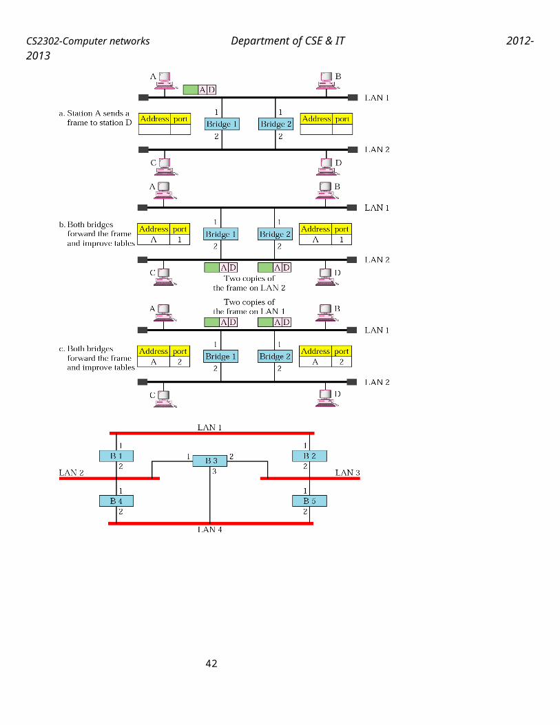
CS2302-Computer networks Department of CSE & IT 2012-2013
–Here all computers are attached to a central point called as hub. In star topology, each station is directly connected to a common central node. Central node is referred as star coupler which uses two point-to-point links, one for transmission in each direction. Its advantages are scalable and easy to identify the fault.
Ring Topology:–Here computers are connected in a closed loop forming a loop. In the ring topology, the network consists of a set of repeaters joined by point-to-point links in a closed loop. The repeater is a device which receives data in one link and transmits them in other link.
Bus Topology:Here all computers are attached to a single long cable. Bus topology uses a multipoint medium and all stations are attached through appropriate hardware interfacing known as a tap. A full duplex operation is used for transmission and reception of data in a bus.
Tree topology is generalization of bus topology. Transmission medium is a branching cable with no closed loops. It begins at a point known as head end, where one or more cables start, and each of these may have branches.
42

CS2302-Computer networks Department of CSE & IT 2012-2013
10 b) Explain the following: Segmentation and reassembly. (April 2011)Segmentation and reassembly A message is divided into segments and each segment contains a sequence number. These numbers enable the Transport layer to reassemble the message correctly upon arriving at the destination. The packets lost in the transmission is identified and replaced.
When the size of the data unit received from the upper layer is too long for the network layer datagram or data link layer frame to handle, the transport protocol divides it into smaller usable blocks. The dividing process is called segmentation.
43