· Web viewThe operation of remote control circuit represents transmitting part and the operation...
6
International Journal of Science, Engineering and Technology Research (IJSETR) Volume 1, Issue 1, July 2012 Abstract — The functions of remote controlled fire fighting robot are described in this journal. It includes two main parts: one is transmitting and another is receiving. In which, two sets of RF Modules are used. One is used to transmit the data to the motor drivers and another is used to know the condition on fire. The whole system of the fire fighting robot is operated by the microcontroller PIC16F887. In this system, the motors are driven by the L298 and ULN2003 drivers. The operator controls the robot with the aid of wireless camera mounted on the robot. When the fire is detected, it is extinguished by water in the tank attached to the robot. But, if the temperature of fire site is above , the alarm will be ringing so that the operator can control the fire fighting robot go back and avoid the damage of it. . Keywords—Microcontroller,L298, ULN2003. I.INTRODUCTION Firefighting is an important but dangerous occupation. A firefighter must be able to get to a fire quickly and safely extinguish the fire, preventing further damage and reduce fatalities. Recently, it has sometimes been impossible for fire-fighting personnel to access the site of a fire, even as the fire causes tremendous property damage and loss of human life, due to high temperatures or the presence of explosive materials. Thus, technology has finally bridged the gap between firefighting and machines allowing for a more efficient and effective method of firefighting. So, robots are designed to find a fire, before it rages out of control, could one day work with Phyo Wai Aung, Mechatronic, Mandalay Techanological University, ., (e-mail: [email protected]). Mandalay, Myanmar, +959402550982 Wut Yi Win Mechatronic, Mandalay Technological University, Mandalay, Myanmar, +959259067371., (e-mail: [email protected]). firefighters greatly reducing the risk of injury to victims. These robots can be controlled by a human operator, sometimes from a great distance. Occasionally, autonomous firefighting robots can be found [1]. Many projects for assisting the firefighters have been developed by different technicians of various countries. The Tokyo Fire Department developed robots that can perform tasks that put firefighters at risk. One of these robots is Rainbow 5, which has the ability to remove obstacles from its path and also has a two-nozzle system from which water and foam are shot out. The other is Robogat that rides on a monorail which is mounted on the ceiling of the tunnels. Roboget is an autonomous robot that can automatically detect, using its onboard thermal sensors and cameras and being extinguishing a fire located in the tunnel, but it can also be remotely operated by a technician. The robot has a continuous supply of water/foam through a pipe running alongside the monorail. The whole system is also built with the ability to resist temperatures up to 1000 [2]. So, it can be said that firefighting robots can be designed and constructed differently with the ideas of own creation. II. SYSTEM BLOCK DIAGRAM OF REMOTE CONTROLLED FIRE FIGHTING ROBOT Figure 1 shows the overall system of the robot. Firstly, when the circuits are started, PIC16F628 is reading the sensor data and then sending data to RF transmitter that transmits humidity and temperature data to the remote control. During that time, RF receiver receives the data and PIC16F887 on remote control is processing data received from RF module and keypad. And, not only push- buttons input command but also humidity and temperature values are shown on LCD display. Secondly, microcontroller sends 1 All Rights Reserved © 2012 IJSETR Remote Controlled Fire Fighting Robot Phyo Wai Aung, Wut Yi Win
Transcript of · Web viewThe operation of remote control circuit represents transmitting part and the operation...
International Journal of Science, Engineering and Technology Research (IJSETR)Volume 1, Issue 1, July 2012
Abstract — The functions of remote controlled fire fighting robot are described in this journal. It includes two main parts: one is transmitting and another is receiving. In which, two sets of RF Modules are used. One is used to transmit the data to the motor drivers and another is used to know the condition on fire. The whole system of the fire fighting robot is operated by the microcontroller PIC16F887. In this system, the motors are driven by the L298 and ULN2003 drivers. The operator controls the robot with the aid of wireless camera mounted on the robot. When the fire is detected, it is extinguished by water in the tank attached to the robot. But, if the temperature of fire site is above , the alarm will be ringing so that the operator can control the fire fighting robot go back and avoid the damage of it.
.
Keywords—Microcontroller,L298, ULN2003.
I. INTRODUCTION
Firefighting is an important but dangerous occupation. A firefighter must be able to get to a fire quickly and safely extinguish the fire, preventing further damage and reduce fatalities. Recently, it has sometimes been impossible for fire-fighting personnel to access the site of a fire, even as the fire causes tremendous property damage and loss of human life, due to high temperatures or the presence of explosive materials. Thus, technology has finally bridged the gap between firefighting and machines allowing for a more efficient and effective method of firefighting. So, robots are designed to find a fire, before it rages out of control, could one day work with firefighters greatly reducing the risk of injury to victims. These robots can be controlled by a human operator, sometimes from a great distance. Occasionally, autonomous firefighting robots can be found [1].
Many projects for assisting the firefighters have been developed by different technicians of various countries. The Tokyo Fire Department developed robots that can perform tasks that put firefighters at risk. One of these robots is Rainbow 5, which has the ability to remove obstacles from its path and also has a two-nozzle system from which water and foam are shot out. The other is Robogat that rides on a monorail which is mounted on the ceiling of the tunnels. Roboget is an autonomous robot that can automatically detect, using its onboard thermal sensors and cameras and being extinguishing a fire located in the tunnel, but it can also be remotely operated by a technician. The robot has a continuous supply of water/foam through a pipe running alongside the monorail. The whole system is also built with the ability to resist temperatures up to 1000 [2]. So, it can be said that firefighting robots can be designed and constructed differently with the ideas of own creation.
Phyo Wai Aung, Mechatronic, Mandalay Techanological University, ., (e-mail: [email protected]). Mandalay, Myanmar, +959402550982
Wut Yi Win Mechatronic, Mandalay Technological University, Mandalay, Myanmar, +959259067371., (e-mail: [email protected]).
II.SYSTEM BLOCK DIAGRAM OF REMOTE CONTROLLED FIRE FIGHTING ROBOT
Figure 1 shows the overall system of the robot. Firstly, when the circuits are started, PIC16F628 is reading the sensor data and then sending data to RF transmitter that transmits humidity and temperature data to the remote control. During that time, RF receiver receives the data and PIC16F887 on remote control is processing data received from RF module and keypad. And, not only push-buttons input command but also humidity and temperature values are shown on LCD display. Secondly, microcontroller sends keypad data to another RF transmitter that transmits signal to the robot.
Finally, another PIC16F887 on the robot is processing and analysing the data from the remote control. The microcontroller controls the motor drivers in accordance with the data received from RF receiver on the robot. The operator can control the robot and can see the situation of extinguishing with the help of wireless camera mounted on the robot.
Figure 1. Overall Block Diagram of the System
III. OPERATION OF THE CONTROL CIRCUITS
In this journal, the two circuits are needed to control the robot; transmitting circuit and receiving circuit. The operation of remote control circuit represents transmitting part and the operation of the motor control circuit represents receiving part. In the remote control circuit, PIC16F887 is the main controller interfacing with RF module and push buttons. The RF module transmits serial data with the baud rate 300bps. There are seven push buttons in the circuit assigned as from Sw1 to Sw7. Sw1 is used for ‘Forward’ command, Sw2 for ‘Reverse’, Sw3 for ‘Right’, Sw4 for ‘Left’, Sw5 for ‘Step+’, Sw6 for ‘Step-’ and the last push button Sw7 is used for ‘Pump’. Respective signal (word) of each button will appear on the LCD display.
In the receiving circuit, PIC16F887 is also selected as the main controller to interface with other devices. There are four motors; right DC motors (M1), left DC motor (M2), one stepper motor and pump motor.
1All Rights Reserved © 2012 IJSETR
Remote Controlled Fire Fighting RobotPhyo Wai Aung, Wut Yi Win

International Journal of Science, Engineering and Technology Research (IJSETR)Volume 1, Issue 1, July 2012
A. Circuit operation of the transmitting partWhen push buttons are pressed, RF module transmits
signal as serial data to the robot. By pressing each corresponding button, the operator can control simultaneously not only the robot movement but also extinguishing. While performing these actions, the operator can check whether the command is correct or not with the help of LCD display. The circuit is supported with 5V and 12V DC supply. The transmitting circuit diagram is shown in figure 11.
Figure 11. Transmitting Circuit
B. Circuit operation of the receiving partAll the motors are driven by the command signal
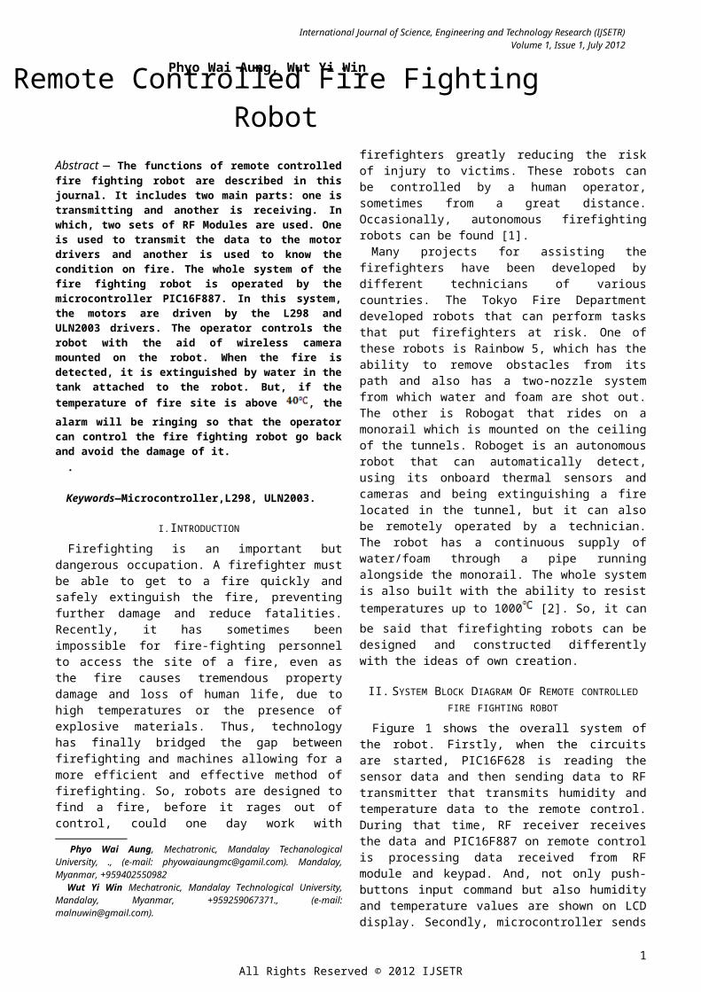
received from the remote control device. The PIC16F887 is also used as the main microcontroller to interface with other devices by receiving the data from RF receiver. The robot is moved to the fire site with the help of two DC motors driven by L298. Right and left DC motors are used to turn the robot right/left or forward/backward or stop. And then, the robot is commanded to extinguish the fire site with spraying water in the tank. The sprinkler can be controlled up or down by applying stepper motor. The stepper motor is driven by ULN2003. The circuit is supported with 5V and 12V DC supply. The receiving circuit is described in figure 12.
Figure 12. Receiving Circuit
IV. MAIN COMPONENTS OF ROBOT CONTROL SYSTEM
In this design, the following main components are mainly used for controlling the fire fighting robot.
In this paper, the system is mainly composed of three parts; the first part is RF transmitting and receiving data, the second is the PIC microcontroller and the third is driving the motors. The robot is completely controlled by wireless remote. In the remote control, RF modules, PIC16F887, LCD display and alarm are included. The control system consists of the following devices; RF modules, PIC16F887, L298 Driver, ULN2003 Driver, water pump, DC motors and stepper motor are included.
A. Wireless control with RF modulesThis radio frequency (FR) transmission system employs
Amplitude Shift Keying (ASK) with transmitter/receiver (Tx/Rx) pair operating at 434 MHz. The transmitter module takes serial input and transmits these signals through RF. The transmitted data is received by an RF receiver operating at the same frequency as that of the transmitter [3]. The maximum baud rate is 9600 bps. But, to get less error, 300 bps is used.
There are two parts; transmitting and receiving. For motor control, in transmitting part, seven push buttons are used to input the data with defined password for the RF transmitter. In receiving part, RF module receives data only when the configured password for this module is read and sent signal to the controller to drive the motors.
For Humidity sensor, the temperature and humidity data are read and transmitted by RF module with defined password for this module. Then, the receiver accepts the data and sends these data to the microcontroller. These data are displayed on LCD.
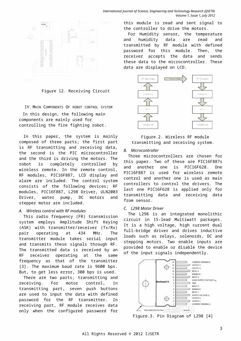
Figure.2. Wireless RF module transmitting and receiving system.
B. MicrocontrollerThree microcontrollers are chosen for this paper. Two of
these are PIC16F887s and another one is PIC16F628. One PIC16F887 is used for wireless remote control and another one is used as main controllers to control the drivers. The last one PIC16F628 is applied only for transmitting data and receiving data from sensor.
C. L298 Motor DriverThe L298 is an integrated monolithic circuit in 15-lead
Multiwatt packages. It is a high voltage, high current dual full-bridge driver and drives inductive loads such as relays, solenoids, DC and stepping motors. Two enable inputs are provided to enable or disable the device of the input signals independently.
2All Rights Reserved © 2012 IJSETR
International Journal of Science, Engineering and Technology Research (IJSETR)Volume 1, Issue 1, July 2012
Figure.3. Pin Diagram of L298 [4]The emitters of the lower transistors of each bridge are
connected together and the corresponding external terminal can be used for the connection of an external sensing resistor. An additional supply input is provided so that the logic works at a lower voltage [4]. The robot motion is controlled by wireless remote. Microcontroller is connected with all drivers to control the rotation of the motors. L298 is used to drive the two right/left DC motors simultaneously.
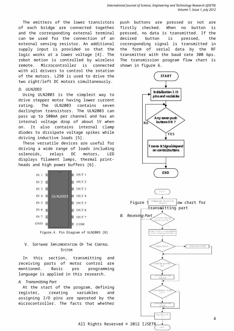
D. ULN2003Using ULN2003 is the simplest way to drive stepper
motor having lower current rating. The ULN2003 contains seven darlington transistors. The ULN2003 can pass up to 500mA per channel and has an internal voltage drop of about 1V when on. It also contains internal clamp diodes to dissipate voltage spikes while driving inductive loads [5].
These versatile devices are useful for driving a wide range of loads including solenoids, relays DC motors, LED displays filament lamps, thermal print-heads and high power buffers [6].
Figure.4. Pin Diagram of ULN2003 [8]
V. SOFTWARE IMPLEMENTATION OF THE CONTROL SYSTEM
In this section, transmitting and receiving parts of motor control are mentioned. Basic pro programming language is applied in this research.
A. Transmitting PartAt the start of the program, defining register, creating
variables and assigning I/O pins are operated by the microcontroller. The facts that whether push buttons are pressed or not are firstly checked. When no button is pressed, no data is transmitted. If the desired button is pressed, the corresponding signal is transmitted in the form of serial data by the RF transmitter with the baud rate 300
bps. The transmission program flow chart is shown in figure 6.
Figure 5. Program flow chart for transmitting part
B. Receiving Part
Figure 6. Program flow chart for receiving part
3All Rights Reserved © 2012 IJSETR
International Journal of Science, Engineering and Technology Research (IJSETR)Volume 1, Issue 1, July 2012
At the start of the program, defining register, creating variables and assigning I/O pins are operated by the microcontroller. The microcontroller receives the serial data from the remote control to interface with the drivers. There are four motors in the circuit. Each of these motors can be controlled to rotate forward or backward by the instruction of the program. The program flow chart for receiving part is described in figure 7.
VI. ALGORITHM OF SOLAR TRACKING SYSTEM
After installing program in the microcontrollers, all the circuits are tested. But, an error has been found when the remote control and sensor are being operated simultaneously. This error is that all of the receivers catch all the signals from sensor and remote control. This is caused because of using two RF modules at the same frequency. So, the researcher has to assign the two different passwords in the program for each RF modules. One password is for motor control and another for sensor.
Therefore, it can be said that the researcher has modified the present program to new one. Moreover, this new program is applied not to appear any error. After reinstalling the modified program in each microcontroller, each of the RF receivers obtains the desired data transmitted from the relevant RF transmitters, respectively. Finally, the successful accomplishment of practical circuit operation can be found. Some results of testing conditions are displayed on the LDC as shown in figures 7, 8, 9, 10.
Figure 7. Control circuit with LCD and seven push buttons
Figure 8. Result of ‘Forward’command by push button (forward)
Above figure.18 shows the result of robot’s forward movement while the ‘Forward’ push button on the remote control is pressing. The values of humidity and temperature can also be read while controlling the robot.
Figure 9. Result of ‘Pump’ command by push button (pump)
Figure 10. Result of ‘Step+’ command by push button (Sprinkler arm up)
Figure 11. The design construction of fire fighting robot
VIII. CONCLUSIONS This journal represents a fire fighting robot using RF
remote control and it is designed for only as a sample. This sample can be based to construct fire fighting robot practically used in dealing with the fire on large scale. Such robots as Spy robot, mine detecting robot, Rescue robot, Toxic removing robot, Military robot, etc, are also controlled by wireless RF communication. So, it can be said that RF communication is effective and reliable usage compared with the advancement of modern technology.
ACKNOWLEDGMENT
The author is very thankful to Dr. Myint Thein, Rector of Mandalay Technological University, for his encouragement, invaluable permission and his kind support in carrying out this paper work.
The author is deeply grateful acknowledge Dr. Wut Ye Win, head of Department of Mechatronic Engineering, Mandalay Technological University for her warmly
4All Rights Reserved © 2012 IJSETR

International Journal of Science, Engineering and Technology Research (IJSETR)Volume 1, Issue 1, July 2012
encouragement, timely guidance, precious suggestions and directions to accomplish this research. The author would like to express his gratitude to Dr.Kyaw Thiha, Dr. Nu Nu Win, Associate Professor and Daw Wai Phyo Ei, Lecturer, for their good guidance and suggestions.
.
REFERENCES
[1] William Dubel, Hector Gongora, Kevin Bechtold and Daisy Diaz, An Autonomous Firefighting Robot; Florida International University, Mivami, FL 33199. (2013)
[2] Himanshu Dedge, Firefighting Robot; A Remotely-Operated Robotic Fire-Fighting Device,STEM Research Project, Massachusetts Academy of Math and Science, 14/2/2013.
[3] Temperature and humidity sensor with RF modules- Geeetech Wiki. http://www.geeetech.com.10/3/2013.
[4] http://www.st.com, January 2000.[5] GET AMAZED, T h u r s d a y, M a y 2 9, 2 0 0 8[6] ST Microelectronics GROUP OF COMPANIES,
http://www.st.com.
5All Rights Reserved © 2012 IJSETR