€¦ · Web viewRail breakage almost always occurs before the defect becomes visible. Action...
71
Edition: June 2009 Specification: Part 1050 Rail and Rail Joints PART 1050 RAIL AND RAIL JOINTS This Part is PTSOM's Code of Practice, Volume 2 – Train System (CP2) "Track Support Systems" CP-TS-961 CONTENTS 1. PURPOSE AND SCOPE........................................................1 2. NEW RAIL.................................................................3 3. RECYCLED OR PART WORN RAIL FOR TRACK CONSTRUCTION........................3 4. RAIL JOINTS..............................................................5 5. WELDED RAIL JOINTS AND REPAIR WELDING....................................6 6. MONITORING AND MAINTENANCE OF WELDED RAILS..............................11 7. NON-WELDED, INCLUDING MECHANICAL, RAIL JOINTS...........................12 8. MONITORING AND MAINTENANCE OF NON-WELDED RAIL JOINTS....................16 9. RAIL WEAR...............................................................19 10. MONITORING AND MAINTENANCE OF RAIL WEAR...............................21 11. REPAIR OF DEFECTIVE RAILS AND WELDS...................................23 12. RAIL DISCONTINUITIES IN WELDED RAILS..................................23 14. DOCUMENTATION.........................................................26 A1 APPENDIX 1: RAIL DEFECTS - TYPES, POSITIONS AND SIZING................28 A2 APPENDIX 2: RAIL DEFECT CATALOGUE.....................................31 1. PURPOSE AND SCOPE 1.1 Purpose The purpose of this part is to set standards to ensure that: (a)the selection of rails and rail joints is appropriate to the requirements of the railway; (b)appropriate inspection and maintenance procedures are carried out; (c)if rail or rail joint failure occurs, appropriate action is taken; (d)the selection of rail lubricators is appropriate to the requirements of the railway; (e)appropriate inspection and maintenance procedures of rail lubricators is carried out. 1.2 Principles This part complies with the principles set out in the "Code of Practice for the Defined Interstate Rail Network", Volume 4, Part 2, Section 1. 1.3 Scope DPTI XXCxxx Page 1
Transcript of €¦ · Web viewRail breakage almost always occurs before the defect becomes visible. Action...
Edition: June 2009 Specification: Part 1050 Rail and Rail Joints
PART 1050
RAIL AND RAIL JOINTS
This Part is PTSOM's Code of Practice, Volume 2 – Train System (CP2) "Track Support Systems" CP-TS-961
CONTENTS
1. PURPOSE AND SCOPE............................................................................................................................. 12. NEW RAIL.................................................................................................................................................. 33. RECYCLED OR PART WORN RAIL FOR TRACK CONSTRUCTION...............................................34. RAIL JOINTS.............................................................................................................................................. 55. WELDED RAIL JOINTS AND REPAIR WELDING...............................................................................66. MONITORING AND MAINTENANCE OF WELDED RAILS..............................................................117. NON-WELDED, INCLUDING MECHANICAL, RAIL JOINTS...........................................................128. MONITORING AND MAINTENANCE OF NON-WELDED RAIL JOINTS.......................................169. RAIL WEAR.............................................................................................................................................. 1910. MONITORING AND MAINTENANCE OF RAIL WEAR.................................................................2111. REPAIR OF DEFECTIVE RAILS AND WELDS...............................................................................2312. RAIL DISCONTINUITIES IN WELDED RAILS................................................................................2314. DOCUMENTATION............................................................................................................................. 26A1 APPENDIX 1: RAIL DEFECTS - TYPES, POSITIONS AND SIZING.............................................28A2 APPENDIX 2: RAIL DEFECT CATALOGUE........................................................................................31
1. PURPOSE AND SCOPE
1.1 Purpose
The purpose of this part is to set standards to ensure that:
(a) the selection of rails and rail joints is appropriate to the requirements of the railway;
(b) appropriate inspection and maintenance procedures are carried out;
(c) if rail or rail joint failure occurs, appropriate action is taken;
(d) the selection of rail lubricators is appropriate to the requirements of the railway;
(e) appropriate inspection and maintenance procedures of rail lubricators is carried out.
1.2 Principles
This part complies with the principles set out in the "Code of Practice for the Defined Interstate Rail Network", Volume 4, Part 2, Section 1.
1.3 Scope
1.3.1 Rails, rail joints and rail lubrication
This part specifies general procedures for the design/rating, acceptance, monitoring and maintenance of:
(a) new and recycled rail;
(b) temporary and permanent joints including flash butt welded joints, alumino-thermic and non-welded (i.e. fishplated) joints; and
(c) rail lubricators and rail lubrication.
DPTI XXCxxx Page 1

Edition: June 2009 Specification: Part 1050 Rail and Rail Joints
1.3.2 Rail end batter, wear, repair welding and weld misalignment
This part specifies general procedures for managing:
(a) rail end batter;
(b) rail wear;
(c) repair welding of "V" crossings, rail end batter and wheel burns with manual arc or MIG repair welds;
(d) welded rail misalignments.
1.4 References
1.4.1 Industry code of practice and report
(a) Code of Practice for the Defined Interstate Rail Network, volume 4 (Track, Civil and Electrical Infrastructure), part 2 (Infrastructure Principles), section 1: Rails
(b) Code of Practice for the Defined Interstate Rail Network, volume 4 (Track, Civil and Electrical Infrastructure), part 2 (Infrastructure Principles), Appendix E: Target rail profiles for grinding.
(c) Railways of Australia (Australasian Railway Association) report ‘WZ/89/A/92 Ultrasonic Testing of Rail in Railway Applications.’
1.4.2 Australian StandardsAS 1050.1 Methods for the analysis of iron and steel Part 1: Sampling iron and steel for
chemical analysis AS 1085.1 Railway permanent way material Part 1: Steel rails AS 1085.1 (1980) Railway permanent way material Part 1: Steel rails AS 1085.2 Railway permanent way material Part 2: FishplatesAS 1085.4 Railway permanent way material Part 4: Fishbolts and nutsAS 1085.7 Railway permanent way material Part 7: Spring washersAS 1085.11 Railway permanent way material Part 11: Head-hardened rails AS 1085.12 Railway permanent way material Part 12: Glued insulated joint assembliesAS 1085.15 Railway permanent way material Part 15: Aluminothermic rail welding AS 1554 Structural steel welding – Part 1: Welding of steel structures AS 2083 Calibration blocks and their methods of use in ultrasonic testing
1.4.3 PTSOM documents
(a) CP2i. CP-TS-952: Part 2, Structure and applicationii. CP-TS-953: Part 3, Infrastructure management and principlesiii. CP-TS-960: Part 10, Track support systemsiv. CP-TS-964: Part 14, Rail stress control
(b) PTSOM/Infrastructure Services Proceduresi. QP-IS-002: Quality Procedure/Work Instruction Developmentii. QP-IS-501: Document and Data Controliii. Cprd/prc/046 Records Management:
1.4.4 PTSOM drawings
Note: Drawings of PTSOM temporary or permanent rail joint designs are shown in Table 7.6.5.
DPTI XXCxxx Page 2

Edition: June 2009 Specification: Part 1050 Rail and Rail Joints
2. NEW RAIL
2.1 Standard New Rail Types
2.1.1 New rail
All new rail for open track shall be a minimum AS 50 kg non head hardened unless noted otherwise. All new rail for points and crossings and interconnecting track shall be AS 60 kg unless noted otherwise. Points and crossings rail to be head-hardened.
2.1.2 Conforming with standards
New rail shall conform with the following criteria:
(a) All 50 kg and 60 kg rail shall comply with AS 1085.1 or AS 1085.11.
(b) 47 kg and 53 kg rail cross section shall comply with AS 1085.1 (1980). All other properties shall comply with AS 1085.1 or AS 1085.11.
(c) Certification of compliance, from the manufacturer, with relevant standards shall be supplied.
(d) A records shall be kept of where each certified order of rail is used in track
2.2 Non-Standard New Rail Types
Rail sizes other than those specified in sub-section 2.1 may be used subject to demonstration, through appropriate analysis and/or testing, that they are suitable for the operational task. Rail wear limits for these alternative rail sizes should be determined during the process. CP-TS-953 (Infrastructure management and principles) outlines the processes, which shall be used to determine the acceptability of any new rail.
2.3 Rail Acceptance
(a) New rail prior to its use in track shall be assessed and certified for use in accordance with sub-sections 2.1 or 2.2.
(b) Recycled rail prior to its reuse in track shall be assessed and certified for use in accordance with section 3.0.
2.4 Minimum Rail Lengths
(a) The minimum rail lengths in points and crossings shall be as shown on authorised drawings.
(b) Except as specified in sub-clause (a), the preferred minimum length rails used on main lines shall be as shown in Table 2.4.
TABLE 2.4: MINIMUM RAIL LENGTHS
Straight or curved track Welded joints both ends; welded joint one end, fishplated joint the other
Fishplated joints both ends
On straight track or curves > 800m radius
3m as shown in CP-TS-960 (Track
On curves ≤ 800m radius 5m support systems)Except as specified in sub-clause (a), the absolute minimum rail length (anywhere) shall be 2.2m
3. RECYCLED OR PART WORN RAIL FOR TRACK CONSTRUCTION
3.1 Recycled Or Part Worn Rail
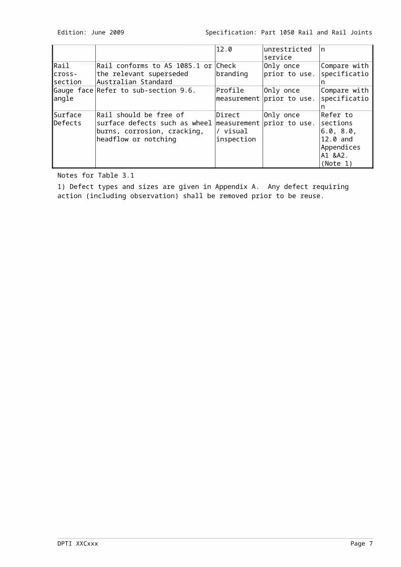
Recycled or part worn rail defines all rail that has previously carried traffic, including rail used for closures and inserts. Prior to use recycled or part worn rail shall be examined for conformity with the criteria in Table 3.1.
DPTI XXCxxx Page 3

Edition: June 2009 Specification: Part 1050 Rail and Rail Joints
TABLE 3.1: RECYCLED OR PART WORN RAIL
Factor Specification Method of test Frequency ortiming of test
Method of assessment
Defects in rails and welds
Defects should be identified and classified as detailed in sections 6.0, 8.0 and 12.0.
Refer to sections 6.0, 8.0 and 12.0.
Ultrasonic testing as required by Figure 3.1.
Refer to clauses sections 6.0, 8.0 and 12.0.
Wear limits Refer to section 9.0. Measurement of wear
Once only prior to unrestricted service
Refer to section 10.0
Metallurgical properties
No testing is necessary if the rail conforms to AS 1085.1 or the relevant superseded Australian Standard or has extensive proven service under the relevant operating conditions
Not applicable Not applicable Not applicable
Otherwise for each rail type determine suitability in terms of: a) Ultimate yield strengthb) Chemical compositionc) Inclusions;d) Impact resistance;e) Hardness;f) Microstructure
Applicable Australian and International Standards
Once only prior to use of rail type
Review by metallurgist competent in rail examination,testing orevaluation
Location of bolt holes in rail to be welded
The distance from the edge of the bolt hole to the rail end shall be no less than 65mm
Direct measurement / ultrasonic testing
Once only prior to welding
Compare with specification
Adjacent welds
Welds should be no closer than 2.2m from the next weld or the end of the rail. Welds or rail ends should not be located closer than 1.5m from the centre of a glued insulated joint.
Direct measurement
Once only prior to welding
Compare with specification
Adjacent non-welded joints
Joints should be no closer than 6m. Direct measurement
Only once prior to installation.
Compare with specification
Rail end straightness
The rail end straightness should be limited to that which permits the final weld or mechanical joint to comply with section 12.0 on rail discontinuities.
Direct measurement
Compare with specification
Rail twist Complies with to AS 1085.1 or the relevant superseded Australian Standard for twist.
Direct measurement
Once only prior to unrestricted service
Compare with specification
Discontinuities Refer to section 12.0 Refer to section 12.0
Once only prior to unrestricted service
Compare with specification
Rail cross-section
Rail conforms to AS 1085.1 or the relevant superseded Australian Standard
Check branding Only once prior to use.
Compare with specification
Gauge face angle
Refer to sub-section 9.6. Profile measurement
Only once prior to use.
Compare with specification
Surface Defects
Rail should be free of surface defects such as wheel burns, corrosion, cracking, headflow or notching
Direct measurement/ visual inspection
Only once prior to use.
Refer to sections 6.0, 8.0, 12.0 and Appendices A1 &A2. (Note 1)
Notes for Table 3.11) Defect types and sizes are given in Appendix A. Any defect requiring action (including observation) shall be removed prior to be reuse.
DPTI XXCxxx Page 4

Edition: June 2009 Specification: Part 1050 Rail and Rail Joints
Figure 3.1: Rail acceptance – ultrasonic test flow diagram
3.2 Requirements for Reuse / Drifting of Recycled / Part Worn Rail
Recycled or part worn rail reuse must comply with the following rail management principles.
(a) Curved rail removed from track for reuse must be reused on a curve of the same radius as that it was taken out from. Where rail is being reused on the same line, the preference is for rail to go back into the same curve.
(b) Worn rail shall not be transposed – existing worn gauge face shall be the reused gauge face.
(c) Insertion of new rail closure lengths shall only occur in straight sections of track. No new rail profile shall be inserted into an existing curved section of track. Should there be insufficient remaining existing curved rail to complete the curve then the entire length of rail through curve shall be replaced.
(d) Minimum joint spacing, including to GIRJs, shall be in accordance with the requirements of Table 3.1 above.
4. RAIL JOINTS
4.1 Rail Joint Methods
Methods of joining rail to provide continuous support may include the following:
(a) Continuously welded rail (CWR) [see sections 5.0 and 6.0].
(b) Non-welded rail i.e. mechanically jointed rail [see sections 7.0 and 8.0].
(c) A combination of welded and non-welded rail e.g. long welded rail. Note that joints will need to be of adequate strength and the rail should be adequately restrained. The centre portion of long lengths may need to be treated as for CWR.
Associated construction and maintenance instructions are specified in CP-TS-964 (Rail stress control).
All rail on track constructed with concrete sleepers shall be continuously welded (CWR).
DPTI XXCxxx Page 5

Edition: June 2009 Specification: Part 1050 Rail and Rail Joints
Rail joints shall be constructed to be clear of the following locations:
(a) 5m clear of bridge abutments
(b) Road pavement – all joints in level crossings to be contained in medians or outside the roadway.
(c) Clear of any sleeper transition zones (e.g. timber to concrete, timber to steel) Refer 3.5.2 of CP-TS-960 for sleeper transition zones.
4.2 Cutting Of Rail
Rail ends in insulated joints should comply with AS 1085.12. The cut should be in a vertical plane and in the plan view may be square or at an angle of 15º.
Rail saw cutting is the preferred method of cutting rail and it is the only method permissible for preparation of closures to be used for later welding operation. Flame cutting of rails is permitted when welding is to be carried out subject to the conditions set out below:
(a) The method may not be used in any circumstances on head hardened rail except where welding is to be carried out immediately (i.e. within 30 minutes). If this is not possible, 30mm should be cut off the cooled rail ends immediately prior to welding.
(b) For standard carbon rails, flame cut rails should be welded in the same work shift. If this is not possible, 30mm should be cut off the cooled rail ends immediately prior to welding.
(c) The method must not be used in preparing rail ends for installation of a permanent non-welded rail joint.
Both ends of the rail to be welded must be of the same type i.e. either both flame cut or both sawn.
Flame cut rail ends under traffic should be plated with a temporary joint and have a speed restriction of 20km/h or less (depending on the joint design) imposed.
4.3 Drilling Holes In Rail
The drilling of holes in rails should be minimised, e.g. by using rail mounted equipment that does not require drilling of rail.
Marking the centre of the hole to be drilled should be carried out using an appropriate template or equivalent. Holes should be drilled square to the web via use of an appropriate guidance mechanism. Drilling requires appropriate cooling of the drilling tool.
Under no circumstances are flame cut holes permitted in rail or other track components.
The location of boltholes for the installation of mechanical rail joints should be in accordance with the dimensions defined in AS 1085.2 and AS 1085.12, for the fishplates to be used In all other cases, the centre of drilled holes should be within 5mm of the neutral axis of the rail and for all sizes of 41kg/m and greater should not be greater than 27mm in diameter.
5. WELDED RAIL JOINTS AND REPAIR WELDING
5.1 Rail Welding Of Joints
5.1.1 Rail joint weld process
Recommended types of weld processes for joining rails include the following:
(a) Aluminothermic
(b) Flashbutt
Rail welding processes should comply with clauses 5.1.2 and 5.1.3
DPTI XXCxxx Page 6
Edition: June 2009 Specification: Part 1050 Rail and Rail Joints
5.1.2 Flashbutt welding
Welding rail ends together using flashbutt welding should be carried out using a specified process as set out in Table 5.3(a).
5.1.3 Aluminothermic welding
(a) Aluminothermic weld materials should be supplied in accordance with AS 1085.15. Type and proof testing should be carried out using the method and frequency defined in AS 1085.15.
(b) Welding rail ends together and repairing the rail running surface using alumino-thermic welding should be carried out using a specified process set out in Table 5.3(b).
(c) Transport and storage of weld consumables should be in accordance with AS 1085.15. Consumables affected in any way, which will impact on the integrity of the final weld, should not be used.
(d) Approved aluminothermic weld processes are given in Table 5.1.3.
Table 5.1.3 Approved Weld Processes
Weld ApplicationStandard
47kg/m to 47kg/m
50kg/m to 50kg/m
53kg/m to 53kg/m
60kg/m to 60 kg/m
60kg/m to 60kg/m (Head Hardened = H)
(H) 60kg/m to 60kg/m (H)
Junction
47kg/m to 50kg/m
47kg/m to 53kg/m
50kg/m to 53kg/m
53kg/m to 60kg/m
5.1.4 Welding rail joints in Recycled rail in Turnouts
All bolt holes should be removed prior to welding.
5.2 Repair Welding
Manual metal arc or metal inert gas welding
Repairing the rail running surface using manual metal arc (MMA) or metal inert gas (MIG) welding should be carried out using a specified process as set out in Table 5.3(c). These welding processes should not be used for joining rail.
5.3 Other Welding Processes
Welding process types other than the above (e.g. gas pressure welding to join rail) should only be used following testing and commissioning in accordance with CP-TS-953 (Infrastructure management and principles). This should involve a stringent validation process involving metallurgical analysis and thorough laboratory and field testing prior to general application in track.
DPTI XXCxxx Page 7

Edition: June 2009 Specification: Part 1050 Rail and Rail Joints
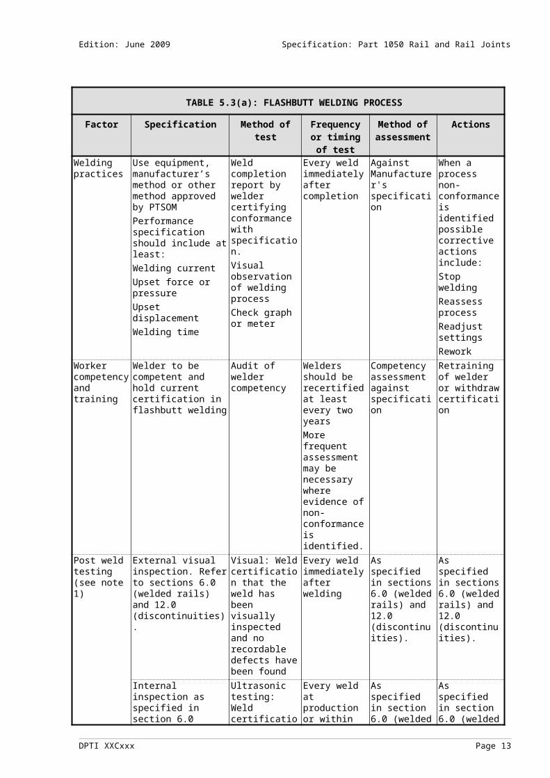
TABLE 5.3(a): FLASHBUTT WELDING PROCESS
Factor Specification Method of test Frequency or timing of test
Method of assessment
Actions
Welding practices
Use equipment, manufacturer’s method or other method approved by PTSOMPerformance specification should include at least:Welding currentUpset force or pressureUpset displacementWelding time
Weld completion report by welder certifying conformance with specification.Visual observation of welding processCheck graph or meter
Every weld immediately after completion
Against Manufacturer's specification
When a process non-conformance is identified possible corrective actions include:Stop weldingReassess processReadjust settingsRework
Worker competency and training
Welder to be competent and hold current certification in flashbutt welding
Audit of welder competency
Welders should be recertified at least every two yearsMore frequent assessment may be necessary where evidence of non-conformance is identified.
Competency assessment against specification
Retraining of welder or withdraw certification
Post weld testing (see note 1)
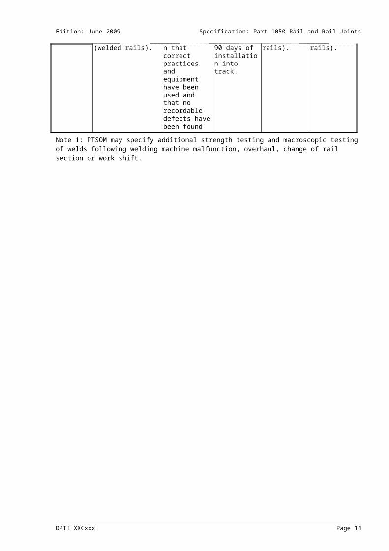
External visual inspection. Refer to sections 6.0 (welded rails) and 12.0 (discontinuities).
Visual: Weld certification that the weld has been visually inspected and no recordable defects have been found
Every weld immediately after welding
As specified in sections 6.0 (welded rails) and 12.0 (discontinuities).
As specified in sections 6.0 (welded rails) and 12.0 (discontinuities).
Internal inspection as specified in section 6.0 (welded rails).
Ultrasonic testing: Weld certification that correct practices and equipment have been used and that no recordable defects have been found
Every weld at production or within 90 days of installation into track.
As specified in section 6.0 (welded rails).
As specified in section 6.0 (welded rails).
Note 1: PTSOM may specify additional strength testing and macroscopic testing of welds following welding machine malfunction, overhaul, change of rail section or work shift.
DPTI XXCxxx Page 8

Edition: June 2009 Specification: Part 1050 Rail and Rail Joints
TABLE 5.3(b): ALUMINOTHERMIC WELDING PROCESS
Factor Specification Method of test Frequency or timing of test
Method of assessment
Actions
Welding practices
Manufacturer’s method or other method approved by PTSOM
Weld completion report by welder certifying conformance with specification.
Visual observation of welding process
Every weld immediately after completion
Against Manufacturer's specification
When a process non-conformance is identified possible corrective actions include:
Stop welding
Reassess process
Rework
Worker competency and training
Welder to be competent and hold current certification in alumino-thermic welding
Audit of welder competency
Welders should be recertified at least every two years
More frequent assessment may be necessary where evidence of non-conformance is identified.
Competency assessment against specification
Retraining of welder or withdraw certification
Post weld testing
External visual inspection. Refer to sections 6.0 (welded rails) and 12.0 (discontinuities).
Visual: Weld certification that the weld has been visually inspected and no recordable defects have been found
Every weld prior to unrestricted traffic immediately after welding
As specified in sections 6.0 (welded rails) and 12.0 (discontinuities).
As specified in sections 6.0 (welded rails) and 12.0 (discontinuities).
Internal inspection as specified in section 6.0 (welded rails).
Ultrasonic testing: Weld certification that correct practices and equipment have been used and that no recordable defects have been found
Every weld within 90 days of weld being installed in track.
As specified in section 6.0 (welded rails).
As specified in section 6.0 (welded rails).
DPTI XXCxxx Page 9

Edition: June 2009 Specification: Part 1050 Rail and Rail Joints
TABLE 5.3(c): MANUAL METAL ARC AND MIG REPAIR WELDS FOR POINTS AND CROSSINGS- PROCESS
Factor Specification Method of test Frequency or timing of test
Method of assessment
Actions
Materials All materials should be supplied to an Australian Standard
To be approved by PTSOM
Prior to use Against the specification
As necessary
Welding practices
Practices for surface preparation and weld process to be approved by PTSOM
Weld completion report by welder certifying conformance with specification.
Every weld immediately after completion
Against Manufacturer's specification
Stop the use of the welding procedure
Reassess the process.
Worker competency and training
Welders should be assessed as competent. Dependent on the risk this may necessitate certification similar to that under AS 1554 for special purpose welding
Audit of welder competency
Welders should be recertified at least every two years
More frequent assessment may be necessary where evidence of non-conformance is identified.
Competency assessment against specification
Retraining of welder or withdraw certification
Post weld testing
External visual inspection. Refer to sections 6.0 (welded rails) and 12.0 (discontinuities).
Visual: Weld certification that the weld has been visually inspected and no recordable defects have been found
Immediately after all welds.
As specified in sections 6.0 (welded rails) and 12.0 (discontinuities).
As specified in sections 6.0 (welded rails) and 12.0 (discontinuities).
Internal inspection as specified in section 6.0 (welded rails).
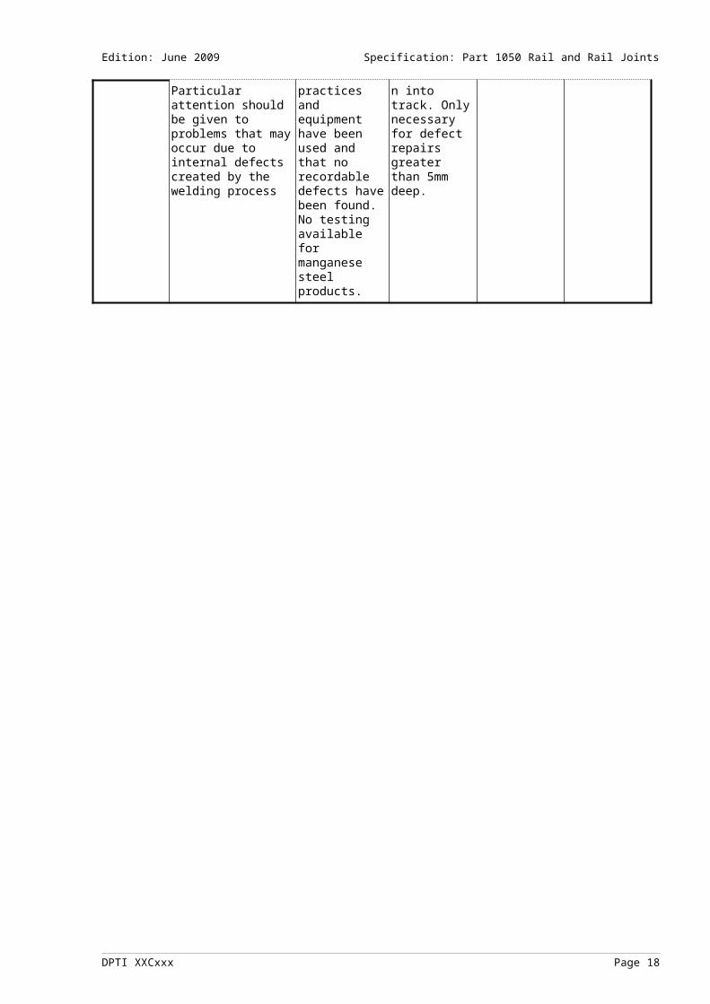
Particular attention should be given to problems that may occur due to internal defects created by the welding process
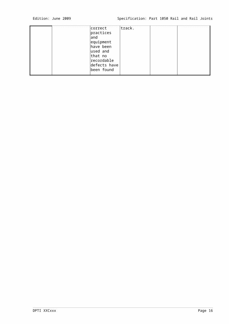
Ultrasonic testing: Weld certification that correct practices and equipment have been used and that no recordable defects have been found. No testing available for manganese steel products.
Every weld at production or within 90 days of installation into track. Only necessary for defect repairs greater than 5mm deep.
As specified in section 6.0 (welded rails).
As specified in section 6.0 (welded rails).
DPTI XXCxxx Page 10

Edition: June 2009 Specification: Part 1050 Rail and Rail Joints
6. MONITORING AND MAINTENANCE OF WELDED RAILS
6.1 Inspection Of Rail And Rail Joints
(a) This section prescribes the minimum requirements for inspection and response to rail and welded joint conditions. For non-welded joints see section 8.0.
(b) Known defects shall be positively identified in track with indelible marking.
(c) Defects other than those described in this sub-section may be identified in track. These defects should be responded to, taking into account both the underlying causes of the defect and its impact on the integrity of the track structure.
(d) Inspection, assessment and maintenance actions of rail and welded rail joints shall include the specific conditions shown in Table 6.1.
TABLE 6.1: RAIL AND WELDED JOINT INSPECTIONS AND ASSESSMENT
Type of inspection or
action
Specific conditions to look for or other actions
Scheduled rail and welded joint inspectionsWalking inspections
a) Identify visually, and report, obvious rail defects and conditions (i.e. indicators of a defect) that may affect the integrity of the track structure including the following:1) broken rails and rail welds;2) rail and rail weld deformations and discontinuities;3) wheel burns;4) damage to rail surface or section;5) unusual patterns of gauge face contact;6) unusual vehicle tracking patterns;7) rail corrugation;8) rail crippling; and9) other obvious indications of defects such as bleeding.
b) Where track circuits are used, these should be considered as an additional method to detect rail failures.
c) Intervals between walking inspections shall not exceed 31 days.Continuous ultrasonic testing
Continuous ultrasonic testing - shall be undertaken every 12 months during the service life of rails to identify and report defects detectable by ultrasonic inspection. Technical aspects of this testing should be based on the Railways of Australia (Australasian Railway Association) report ‘WZ/89/A/92 Ultrasonic Testing of Rail in Railway Applications.’
Detailed inspection
A detailed visual inspection should be carried out:a) for all new welds (see Tables 5.3 (a), (b) and (c)); andb) where the response following the detection of a rail or weld defect is ‘observe’ (see
Appendix 2).Manual ultrasonic testing
a) Manual ultrasonic testing should be carried out in the following situations: 1) at new aluminothermic and flashbutt welds; 2) to confirm suspected defects as indicated by the continuous ultrasonic inspection; 3) where there are suspected defects as found by the walking inspection; 4) when known defects are to be re-inspected and re-assessed. b) Probe configurations shall be carefully selected for the defect being examined. As a basis the following standards shall be used to derive the required work instructions: 1) AS 2083 for calibration of equipment; 2) AS 1085.15 for weld test procedure.
Other detailed inspections
Other detailed inspections may be used in conjunction with ultrasonic inspection, for example magnetic particle, dye penetrant, X-ray, eddy current and magnetic induction.
Assessments and actionDefects detected from inspections should be assessed and reported in accordance with the classification, position and sizing codes as specified in Appendix 2.
DPTI XXCxxx Page 11

Edition: June 2009 Specification: Part 1050 Rail and Rail Joints
6.2 Appendix 1
Appendix 1 shows the following:
(a) defect type codes;
(b) defect position codes;
(c) defect sizing codes.
6.3 Appendix 2
Appendix 2 lists the various types of rail defect. The following information is provided for the various defects:
(a) description;
(b) origins;
(c) manner of propagation;
(d) visual detection information;
(e) failure mode information;
(f) response times and actions.
7. NON-WELDED, INCLUDING MECHANICAL, RAIL JOINTS
7.1 Types Of Non-Welded Rail Joints
Non-welded rail joints may be classified as either:
(a) Permanent rail joints (including glued insulated joints and expansion joints) intended for use in track where special inspections or speed restrictions are not required.
(b) Temporary joints intended for temporary jointing of rails to permit short term passage of trains generally at reduced speed and requiring special inspections when in use.
7.2 Design Specification
Rail joints, including components and assembly details, shall be of an approved design and shall be assembled and used in accordance with the design specifications. The design specifications shall include:
(a) material specification;
(b) assembly requirements, e.g. fastening tension and special locking devices;
(c) conditions for use;
(d) inspection frequency;
(e) maintenance requirements, e.g. ensuring free movement of sliding joints;
(f) speed restrictions for temporary joints.
7.3 Material Certification
Materials shall be certified as having been manufactured to the appropriate standards and specifications.
7.4 Permanent Rail Joints
7.4.1 Fixed or free joints
These joints may be either fixed which are those designed not to move, or free, which are those that have a designed movement.
7.4.2 Types of permanent joints
Types of permanent joints include:
DPTI XXCxxx Page 12
Edition: June 2009 Specification: Part 1050 Rail and Rail Joints
(a) standard bolted joint (free);
(b) mechanical (fixed) - swage fastened e.g. as used in points and crossings;
(c) mechanical insulated (fixed) - normal insulated joint (liners, ferrules, and end posts), coated fishplates;
(d) glued insulation (fixed) - predominantly used in CWR and considered as a single structural unit;
(e) junction joint (free) - used to join different rail sizes.
7.4.3 Swage lock fastenings
In crossings, turnouts and other locations where fixed joints are used, the use of swage lock fastenings in lieu of bolts is an alternative method of fastening. Care should be taken however to ensure that the joint components can support the forces imposed by this type of fastening due to the tensile loading across the fastening.
7.4.4 Approved designs
A junction or other permanent joint not covered by Australian Standards (see clause 7.6.5) shall be either a PTSOM standard design as in table 7.2, or equivalent. An alternative design must:
(a) undergo commissioning which includes a stringent validation process, metallurgical, physical and extensive field testing;
(b) be a current proven design; or
(c) be equal to or exceed the performance of current proven designs.
7.4.5 Insulated joints
(a) All new insulated joints should be Grade A insulated joint assemblies in accordance with AS 1085.12 and use 6 hole joint bars.
(b) Rail ends may be angle cut as provided for in AS 1085.12.
(c) Insulated joints should be centrally suspended between sleepers; ( with a tolerance of 25 mm)
(d) In general, insulating materials that encapsulate fishplates are unsuitable for swage lock fastenings without the application load spreading bars.
7.4.6 Other joints
Expansion switches, junctions and other permanent joints not covered by AS 1085 should be supplied to a design approved by PTSOM.
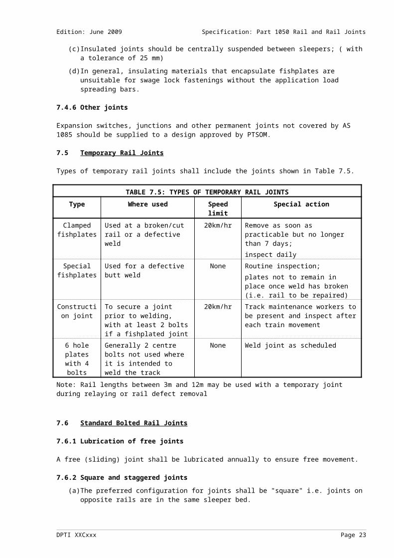
7.5 Temporary Rail Joints
Types of temporary rail joints shall include the joints shown in Table 7.5.
TABLE 7.5: TYPES OF TEMPORARY RAIL JOINTS
Type Where used Speed limit Special actionClamped fishplates
Used at a broken/cut rail or a defective weld
20km/hr Remove as soon as practicable but no longer than 7 days;inspect daily
Special fishplates
Used for a defective butt weld None Routine inspection;plates not to remain in place once weld has broken (i.e. rail to be repaired)
Construction joint
To secure a joint prior to welding, with at least 2 bolts if a fishplated joint
20km/hr Track maintenance workers to be present and inspect after each train movement
6 hole plates with 4 bolts
Generally 2 centre bolts not used where it is intended to weld the track
None Weld joint as scheduled
Note: Rail lengths between 3m and 12m may be used with a temporary joint during relaying or rail defect removal
DPTI XXCxxx Page 13
Edition: June 2009 Specification: Part 1050 Rail and Rail Joints
7.6 Standard Bolted Rail Joints
7.6.1 Lubrication of free joints
A free (sliding) joint shall be lubricated annually to ensure free movement.
7.6.2 Square and staggered joints
(a) The preferred configuration for joints shall be "square" i.e. joints on opposite rails are in the same sleeper bed.
(b) Where staggered joints are used, the "stagger" is defined as the distance measured along the centre line of the track between opposite joints, which are not "square".
(c) Staggered joints shall have a minimum "stagger" of 3 metres.
(d) No more than three joints having a "stagger" of between 3m and 6m shall follow in succession.
(e) There shall be no limit on the number of joints with a "stagger" of more than 6m.
(f) Where staggered joints are used the effect on vehicle resonance should be taken into consideration.
7.6.3 Suspended joints
It is preferred that joints shall be centrally suspended between sleepers. Where this not possible joints should be centrally supported.
7.6.4 Relevant Australian Standards
Manufactured fishplated rail joint assembly components shall conform to the requirements of the appropriate Australian Standard. These standards generally define the requirements with respect to materials and material tests, manufacture, design and specification of the component, and component testing and compliance:
(a) Fishplates - AS1085.2
(b) Fishbolts and nuts - AS1085.4
(c) Spring washers - AS1085.7
(d) Glued insulated joints - AS1085.12
7.6.5 Drawings of rail joints
Drawings of PTSOM rail joint designs are shown in Table 7.6.5.
TABLE 7.6.5: DRAWINGS OF TEMPORARY OR PERMANENT RAIL JOINTS
Drawing no. Date Title326-A1-84-0614326-A1-84-0616326-A1-84-0652326-A2-84-0475326-A2-84-0476326-A2-84-1282326-A2-84-1558326-A3-84-1253326-A3-84-1562326-A1-84-0605
326-A2-84-1446
326-A2-84-1281
326-A2-84-1280
23/05/8423/05/8424/05/8417/05/8418/05/8415/10/8422/11/8415/10/8426/11/8423/05/84
30/10/84
15/10/84
15/10/84
FISH PLATES - JUNCTION FISHPLATES 107AS TO 82ASFISH PLATES - JUNCTION FISHPLATES 107AS TO 94ASFISH PLATES - CLAMP FOR 41 KG/M TO 60 KG/M RAILSFISHPLATES AND DETAILS - FISHPLATE 107 AS (53KG)FISHPLATES AND DETAILS - FISHPLATE 82 AS - 94KGFISHPLATED JOINT - FISHBOLT M24 X 137MM WITH SQUARE NUTFISHPLATED JOINT - FISHBOLT M22 X 110MM WITH SQUARE NUTFISHPLATED JOINT - SPRING WASHER FOR M24 BOLTFISHPLATED JOINT - SPRING WASHER FOR M22 FISHBOLTFISHPLATED JOINT - DETAILS 107 AS RAIL & CAST MANGANESE
STEEL ‘V’ CROSSING 1 IN 8FISHPLATED JOINT - 3°35’ TAPER HEADLOCK (2 BOLT) - M24 H7 BOLT
- 53KG CAST. MANG. ‘V’FISHPLATED JOINT - SPECIAL FISHPLATE - BROKEN THERMIT WELDS
47KG AS RAILFISHPLATED JOINT - SPECIAL FISHPLATE - BROKEN THERMIT WELDS
DPTI XXCxxx Page 14

Edition: June 2009 Specification: Part 1050 Rail and Rail Joints
326-A2-85-0222
326-A2-85-0223
326-A1-84-0615
326-A2-84-1462
326-A2-84-1569
326-A2-84-1447
326-A2-84-0599
30/01/85
30/01/85
23/05/84
31/10/84
26/11/84
30/10/84
23/05/84
53KG AS RAILFISHPLATED JOINT - FISHPLATE 53 KG AS FOR USE WITH FISHPLATE
CLAMPFISHPLATED JOINT - FISHPLATE 47 KG AS FOR USE WITH FISHPLATE
CLAMPFISH PLATES - SPECIAL FOR USE WITH 1 IN 9 CAST MANGANESE
STEEL ‘V’ CROSSING & 94AS RAILFISHPLATED JOINT - 1 IN 9 CAST MANGANESE STEEL ‘V’ CROSSING -
47KG AS RAILFISHPLATED JOINTS - FISHBOLT M24 X 115MM FISHBOLT WITH
SQUARE NUTFISHPLATED JOINT - 3°35’ TAPER WASHER (2 BOLT) - M24 H7 BOLT -
53KG CAST. MANG. ‘V’FISH PLATES - MODIFIED 107 AS FISH PLATE - TO SUIT JOINT 107 AS
RAIL & CAST MANGANESE STEEL ‘V’ CROSSINGNEW DRAWINGS TO BE PREPARED
7.7 Joint Alignment
7.7.1 Misalignment limits
Table 7.7.2 shows the acceptable absolute limits and desirable construction limits for the misalignment of non-welded joints.
7.7.2 Absolute limits
The absolute limits defined in Table 7.7.2 are not recommended for normal track, as their use may lead to severe problems with track geometry deterioration and high impacts causing component deterioration:
TABLE 7.7.2: NON-WELDED RAIL JOINT MISALIGNMENT LIMITS FOR NEW CONSTRUCTION
Factor Specification Method of test Corrective Absolute
limitsDesirable
construction standards
Action(Refer Note)
Peak in running surface
2mm 0 1 metre straightedge & feeler or taper gauge
Realign
Dip in running surface
2mm 0 1 metre straightedge & feeler or taper gauge
Realign or replace if due to rail end batter
Vertical step in rail running surface
1mm 0 100mm straightedge & feeler or taper gauge
Realign or grind
Horizontal step in rail running surface
-1 / +2mm 0 100mm straightedge & feeler or taper gauge
Realign or grind
NOTE: Corrective action for new works shall be undertaken within 7 days.
DPTI XXCxxx Page 15
Edition: June 2009 Specification: Part 1050 Rail and Rail Joints
8. MONITORING AND MAINTENANCE OF NON-WELDED RAIL JOINTS
8.1 Inspection, Assessment And Maintenance Actions
(a) This section prescribes the minimum requirements for inspection and response to non-welded rail joint conditions. For welded rail joints see section 6.
(b) Known defects shall be positively identified in track with indelible marking.
(c) Inspection, assessment and maintenance actions of non-welded rail joints shall include the specific conditions shown in Table 8.1.
TABLE 8.1: NON-WELDED RAIL JOINT INSPECTIONS, ASSESSMENT AND MAINTENANCE ACTIONS
Type of inspection or action Specific conditions to look for or other actionsScheduled inspectionsWalking inspections a) Identify visually, and report, obvious rail defects and conditions (i.e. indicators
of a defect) that may affect the integrity of the track structure including the following:
1) broken, missing or loose bolts;2) broken plates;3) metal flow across joints;4) vertical deformation;5) rail end batter;6) insulation breakdown;7) track circuit bond wire damage;8) other obvious defects or missing components.
b) Intervals between walking inspections shall not exceed 31 days.Unscheduled inspections To be undertaken when a joint is suspected to contain additional defects and is
required to be kept in service.Assessment and method of assessment
Detected defects in non-welded rail joints should be assessed and reported in accordance with the classification, position and sizing as specified in Table 8.2. The actions for each defect and the response time to carry out such actions are also specified in the table. Free movement of sliding joints should be maintained. Where joints are frozen
or poor joint regulation exists the track should be assessed in accordance with the recommendations in CP-TS-964 (Rail stress control).The definition of actions and response times are detailed in Appendices 1 and 2.
For non-welded joints however, "repair or replace" should be interpreted to mean maintenance or reinstallation of the joint to the design specifications.
Maintenance actions and response
a) The actions for each defect and basic response time to carry out remedial action are detailed in Appendices 1 and 2. b) For non-welded joints the "repair or replace" action always implies maintenance or re-installation of the joint to the design specifications.
8.2 Non-Welded Joint Assessment
(a) Free movement of sliding joints should be maintained. Where joints are frozen or poor joint regulation exists the track should be assessed in accordance with the recommendations in CP-TS-964 (Rail stress control).
(b) Detected defects in non-welded rail joints should be assessed and reported in accordance with the classification, position and sizing as specified in Table 8.2. The actions for each defect and the response time to carry out such actions are also specified in the table.
(c) The definition of actions and response times are detailed in Appendix 1. For non-welded joints however, "repair or replace" should be interpreted to mean maintenance or reinstallation of the joint to the design specifications.
DPTI XXCxxx Page 16

Edition: June 2009 Specification: Part 1050 Rail and Rail Joints
TABLE 8.2: RAIL AND NON-WELDED JOINT ASSESSMENT RESPONSES
DEFECT SIZE RESPONSE TIME
ACTION
Fishplate cracks These are cracks or notches located in the area between the 3rd and 4th hole of a fishplate. Visual detection is possible by close examination of the fishplate for signs of cracks and bleeding. Detailed inspection can be carried out by using dye penetrant or similarAny visual cracks, 1 fishplate
Bottom of fishplateOther positions on fishplate
7 days14 days
Reassess or replaceReassess or replace
Any visual cracks, both fishplates Immediately To be assessed by a competent worker and trains to be stopped or piloted
Complete failure: 1 fishplateComplete failure: 1 fishplate and a visible crack in the otherComplete failure: both fishplatesMissing or ineffective bolts (6 bolt joint); ineffective bolts are those which have to be replaced as distinct from loose bolts. 1 on each side ineffective Routine
maintenanceReplace any missing bolts
None, 1 or 2 on one side and 2 on the other side ineffective
1 day Reassess or replace
3 on one side and none or 1 on the other side ineffective
Immediately Assess, and/or apply clamps and apply a speed restriction depending on joint vertical support, longitudinal support and joint gap.May only be left overnight where vertical support is good and where longitudinal support is such as to prevent further significant gap opening. Where left overnight the speed must be limited to no more than 20km/h
3 on one side and 2 or 3 on the other side ineffective
Immediately To be assessed by a competent worker, plates to be clamped and trains to be stopped or piloted.
DPTI XXCxxx Page 17
Edition: June 2009 Specification: Part 1050 Rail and Rail Joints
TABLE 8.2 (continued): RAIL AND NON-WELDED JOINT ASSESSMENT RESPONSES
DEFECT SIZE RESPONSE TIME
ACTION
Loose fishbolts (6 bolt joint) In this defect, the bolts that are holding the joint together are not providing enough clamping force to the plates to ensure integrity of the joint. Excessive vertical or lateral movement of the joint occurs. In general, loose bolts shall be tightened. A loose fishbolt is one where the fishbolt nut provides some but not full compression of the spring washer. See also sub-section 8.31 on each side loose Routine
maintenanceTighten any loose bolts. See also sub-section 8.3
None or 1 on one side and 2 on the other side loose
14 days Reassess, replace or tighten. See also sub-section 8.3
a) 2 on each side loose; or 3 daysb) none or 1 on one side and 3 on the other side loose5 or 6 bolts loose (but with sufficient integrity to provide vertical and lateral support)
1 day
All bolts loose, joint vertical and horizontal support lost
Immediately Replace, tighten, apply clamps or assess and apply speed restriction depending on joint gap and on vertical support and lateral support from track structure. See also sub-section 8.3
Defects in electrical insulation (Insulated joints only)Any Immediately Check to identify any potential signalling problems
and repair in accordance with specificationsEnd batter Rail end batter greater than 2mm measured over 100mm
Immediately Check, assess or speed restrict as necessary
Joint gap defect Where joint gaps are identified as greater than the nominal maximum design gap the joint shall be inspected for fishplate and fishbolt defects and visible rail misalignment or defects. The joint gap may indicate stress control problems, which should be assessed in accordance with CP-TS-964 (Rail stress control).Joint gaps ≥ 15mm and < 20mm Routine
maintenancePlanned maintenance
Joint gaps ≥ 20mm and < 30mm 1 day Check for fishplate and fishbolt defects (especially broken bolts), visible rail discontinuities and defects and stress control problems and take appropriate actions for defects found
Joint gaps ≥ 30mm Immediately Review risk of wheel climb (track curvature, horizontal angle at joint, degree of misalignment of joint, joint vertical and lateral integrity). Apply speed restriction or pilot
Rail defects Any In accordance
with section 6.0In accordance with section 6.0.
Notes:[1] "1 day" is to be taken to mean till the end of daylight hours on the next day.[2] More stringent restrictions should be applied if vertical, lateral or longitudinal support conditions are poor.[3] Any subsequent actions determined from an initial assessment should be carried out within a timescale
consistent with the severity of the problem.
DPTI XXCxxx Page 18

Edition: June 2009 Specification: Part 1050 Rail and Rail Joints
[4] Refer to monitoring and maintenance actions and response in CP-TS-953 (Infrastructure maintenance and principles).
8.3 Spring Washers
Correct tension in fishbolts shall be indicated by the spring washer being fully compressed when the fish-nut is fully tightened. Whenever a fishbolt is un-done for whatever reason the spring washer is to be replaced with a new, unused spring washer to ensure that the correct bolt tension is obtained.
9. RAIL WEAR
9.1 General
This section prescribes the minimum requirements for inspection and the response to the following rail wear conditions:
(a) top wear;
(b) side wear;
(c) gauge face angle.
9.2 Rail Wear
There are generally two rail wear mechanisms, top wear where the rail head is worn down or ground down, and side wear where the rail wears from the gauge face. The allowable limits for top wear and side wear at which the capacity of the rail should be reviewed are given in sub-sections 9.3 and 9.4 respectively. Top wear is the dominant wear mechanism for low rails of curves, tangent tracks and curves of greater radius than 600m. Side wear is the dominant wear mechanism for the high rail of curves sharper than 600m radius.
9.3 Top Wear
The rail top wear limits are shown in Table 9.3:
TABLE 9.3: RAIL TOP WEAR LIMITS
Rail typeNew rail
head areamm²
New railheight mm
Loss of head area limit %
Loss ofheight limit
mm
Worn height limit mm
AS 47kg 2 548 141 40 13 128
AS 50kg 2 729 154 50 18 136
AS 53kg 2 710 157 41 17 140
AS 60kg 3 018 170 39-42 18 152
AS 60kg head hardened
3 018 170 45-47 20 150
Notes to Table 9.3:[1] The rail top wear limit is the worst case of either loss of height limit or loss of head area limit.[2] Loss of head area limits are more critical for side wear. Where rails have more than 10mm of side wear, the loss of head area limit given in Table 9.4 is to be used in the assessment of top wear limit.[3] The limits apply to the worst location, and not the average rail wear, for the segment of track being considered (such as a curve).[4] The limits do not apply to combination of defects, see CP-TS-953 (Infrastructure management and principles). Where combined defects occur assessment should be by a competent worker.[5] When approaching the rail wear limits, factors such as defect types, defect density and defect history should be considered.
DPTI XXCxxx Page 19

Edition: June 2009 Specification: Part 1050 Rail and Rail Joints
9.4 Side Wear
The rail side wear limits are shown in Table 9.4.
TABLE 9.4: RAIL SIDE WEAR LIMITS
Rail typeNew rail
head areamm²
New railhead width
mm
Loss of head area limit %
Loss of headwidth limit mm
Worn head width limit
mm
AS 47kg (94lb) 2 548 70 34 24 46AS 50kg 2 729 70 33 23 47AS 53kg (107lb) 2 710 70 35 24 46AS 60kg 3 018 70 34 24 46AS 60kg head hardened
3 018 70 34 24 46
Notes to Table 9.4:[1] Side wear is measured 16mm below the running surface.[2] The rail side wear limit is the worst case of either loss of width limit or loss of head area limit.[3] The limits apply to the worst location, and not the average rail wear, for the segment of track being
considered (such as a curve).[4] The limits do not apply to combination of defects, see CP-TS-953 (Infrastructure management and
principles). Where combined defects occur assessment should be by a competent worker.[5] When approaching the rail wear limits, factors such as defect types, defect density and defect history should be considered.
9.5 Gauge Face Angle
In order to prevent wheel flange climbing in the presence of a high lateral to vertical (L/V) wheel/rail force ratio, particularly in very tight radius curves, limits are set for the allowable angle on the gauge face of the rail. The gauge face angle of rails should not exceed 26 degrees from vertical over a length of rail of more than 2m. The gauge face angle is measured as the angle between a line perpendicular to the sleeper plane (i.e. the plane of the track) and the line tangential to the rail gauge face where wheel flange contact occurs.
Figure 9.5: Gauge face angle
DPTI XXCxxx Page 20

Edition: June 2009 Specification: Part 1050 Rail and Rail Joints
10. MONITORING AND MAINTENANCE OF RAIL WEAR
10.1 Inspection, Assessment And Maintenance Actions
Inspection, assessment and maintenance actions for rail wear shall include the specific conditions shown in Table 10.1.
TABLE 10.1: RAIL WEAR INSPECTIONS, ASSESSMENT AND MAINTENANCE ACTIONS
Type of inspection or action
Specific conditions to look for or other actions
Scheduled inspectionsWalking inspections a) Identify visually, and report, rail wear defects and conditions (i.e. indicators of a
defect) that may affect the integrity of the track structure including the following:1) high levels of rail wear approaching wear limits, particularly on curves (e.g.
presence of steel filings);2) excessive rail gauge face angle;3) other unusual and obvious wear patterns and defects indicating, for example, poor
vehicle tracking, sharp points in curves or excess/deficient cant.b) Intervals between walking inspections shall not exceed 31 days.
Detailed inspections Detailed inspections:a) may be carried out following a walking inspection, which identifies sections of track
suspected to have head wear near the wear limit. b) shall be carried out every 24 months except as provided for in (a).c) shall include measuring the amount of head wear of rails particularly on curves and
the gauge face angle.Unscheduled inspections
To be undertaken if a worn rail breaks or fails, particularly if this results in a derailment or other incident.
Assessment and method of assessment
a) Rail wear and gauge face angle defects should be reported and action taken when any of the wear limits prescribed are exceeded. Rail wear should be assessed against the limits prescribed in section 9.0.
b) Where the prescribed wear limits are exceeded a rating of the rail may be carried out taking into account local factors and applied speed restrictions. Alternatively, the action should be to re-rail the affected section.
Maintenance actions and response
a) Where the prescribed gauge face angle limits are exceeded the required action is to reinstate an acceptable rail gauge angle (e.g. re-profile in accordance with sub-section 9.5 and 10.2) or re-rail the affected section.b) Where the prescribed rail wear limits are exceeded the required action is to re-rail the affected section. See sub-section 10.2.
DPTI XXCxxx Page 21
Edition: June 2009 Specification: Part 1050 Rail and Rail Joints
10.2 Testing For Rail Wear
Rail testing shall be carried out in accordance with the procedure shown in Figure 10.1 and Table 10.2. For values of A, B, C and D refer to Table 10.2.
Figure 10.2: Procedure for measuring rail wear:
Measure side wear – is it more than 10mmNo Yes
Rerail or Yes Is the remaining Is the remaining Yes Rerail or repair head area < B head area < D repair
No NoIs the side wear Yes Rerail or
> C repairNo
Is the top wear > A Yes Rerail or repair
NoRoutine inspection
Table 10.2: Limits of wear:
Rail Type A B C DTop wear Remaining head
areaSide wear Remaining head
area
AS 47kg 13mm 1529 mm² 24mm 1682 mm²
AS 50kg 18mm 1365 mm² 23mm 1828 mm²
AS 53kg 17mm 1599 mm² 24mm 1761 mm²
AS 60kg 18mm 1750 mm² 24mm 1992 mm²
AS 60kg head hardened
20mm 1600 mm² 24mm 1992 mm²
10.3 Rail Profile
Where rail grinding to achieve a desired cross-sectional profile is undertaken, the profiles shall be determined.
DPTI XXCxxx Page 22
Edition: June 2009 Specification: Part 1050 Rail and Rail Joints
11. REPAIR OF DEFECTIVE RAILS AND WELDS
11.1 General
This section prescribes the welding, materials and processes for repair of the running surface of rails in or out of track. This includes repair welding to damaged rails, V-crossings, switch blades, building up of battered rail ends and wheel burns. It does not include rail joining processes.
11.2 Acceptable Welding Processes
The repair welding of the rail running surface may be carried out using:
(a) aluminothermic welding - see section 3;
(b) manual metal arc and MIG repair welding - see sub-sections 8.4 and 8.5.
Repair of defective rails and welds should be carried out in accordance with Appendices 1 and 2. When a defect is to be removed, consideration should be given to removal of any other identified rail and weld defects in the vicinity.
11.3 Other Welding Methods
Other welding methods may be used but shall be subject to a stringent validation process that shall include metallurgical, physical and extensive field testing.
11.4 Manual Metal Arc And Mig Repair Welding
Manual metal arc and MIG repair welding, including materials, process and post weld testing shall be carried out in accordance with Table 5.3(c).
11.5 Rail Surface Repair Weld Process
A schedule of the different types of rail defect with the inspection requirements, response times and necessary action is shown in Appendices 1 and 2. Note: All repairs should meet the rail surface requirements of section 12.0 (Discontinuities).
12. RAIL DISCONTINUITIES IN WELDED RAILS
12.1 Construction Limits
The construction limits for the control of rail running surface discontinuities during the following processes are given in Table 12.1(a).
(a) laying of rail in track;
(b) production of rail lengths for installation;
(c) insertion of rail welds into track including those for closure rails.
The test measurements should be assessed against the construction standard specifications and appropriate action prior to opening the track for normal traffic.
Internal rail defects arising from construction are covered in section 6.0.
DPTI XXCxxx Page 23

Edition: June 2009 Specification: Part 1050 Rail and Rail Joints
TABLE 12.1(a): WELDED RAIL DISCONTINUITIES (NEW WELDS) [SEE NOTE 1]
Factor Absolute limits Construction limits Method of test Corrective action
Peak in running surface
+0.5mm over 1m +0.0mm to +0.3mm over 1m.
1m reference and height difference measure [see note 2]
Remove or grind
Dip in running surface 0 0 1m reference and height difference measure
Remove
Gauge widening due to change in rail
0.5mm over 1m 0.5mm over 1m 1m reference and height difference measure
Remove or bend
Gauge narrowing due to change in rail
0.5mm over 1m 0.5mm over 1m 1m reference and height difference measure
Remove or grind
Vertical step in rail running surface
±0.3mm over 100mm
±0.15mm over 100mm
100mm reference and height difference measure
Remove or grind
Horizontal step in rail running surface
±0.3mm over 100mm
±0.15mm over 100mm
100mm reference and height difference measure
Remove or grind
Notes:
[1] Requirements for rail with non-welded rail joints are given in Table 7.7.2.[2] For example a 1m straight edge and feeler or taper gauge.[3] Tolerances are only applied to areas of the rail where wheel contact may occur.
12.1.1 Discontinuities in semi-finished welds
Where there is insufficient time for the new weld to fully cool to the same temperature as the adjoining rail, thus preventing final grinding to be completed, the weld can be left in a semi-finished state for a period not exceeding 14 days. It is important that in this state the weld is left peaked to allow sufficient metal to be left for final grind.The geometric tolerance on semi-finished welds is given in Table 12.1(b):
TABLE 12.1(b): WELDED RAIL DISCONTINUITIES (NEW WELDS) [SEE NOTE 1]
Factor Standard for semi-finished statePeak in running surface +0.8mm to +1.2mm over 1m.Dip in running surface Absolutely no dip allowed (Refer Note 1)Gauge widening due to change in rail 0.5mm over 1m maximumGauge narrowing due to change in rail 0.5mm over 1m maximumVertical step in rail running surface ±0.3mm over 100mmHorizontal step in rail running surface ±0.3mm over 100mm
Notes:
[1] As the weld is still cooling it must be left proud of the adjoining rail head to ensure sufficient metal is present for the cooled state therefore there must be no dip
12.2 Rail Discontinuities Assessment
The assessment of discontinuities in rails should incorporate the measures in clauses 12.2.1 and 12.2.2.
12.2.1 Running surface discontinuities in welded rails
This clause gives limits for the control of rail running surface discontinuities identified from track inspection. The limits given are recommended limits only for existing track and are not recommended for normal track construction and maintenance work (refer to sub-section 12.1). The limits are not intended to indicate best practice as discontinuities of the magnitude defined in Table 12.2.1 may lead to a need for a significantly higher
DPTI XXCxxx Page 24

Edition: June 2009 Specification: Part 1050 Rail and Rail Joints
maintenance input than track with good geometry. Where discontinuities of these magnitudes are left in track, problems with track geometry deterioration and high impact, causing ballast and track component deterioration, can be expected. The detection of these types of defects during inspection will generally be through identification of these secondary effects. In some modes of track deterioration, timber sleepered track has a better inherent ability to tolerate impacts resulting in a lower rate of deterioration than for concreted track.
TABLE 12.2.1: WELDED RAIL DISCONTINUITIES (MAINTENANCE) ASSESSMENT
Factor Limit Method of test Corrective action
Peak in running surface 2mm over 1m 1m reference and height difference [see note 2]
Remove or grind
Dip in running surface 2mm over 1m 1m reference and height difference
Remove or lift
Gauge widening due to change in rail
2mm over 1m 1m reference and height difference
Remove or bend
Gauge narrowing due to change in rail
2mm over 1m 1m reference and height difference
Remove or grind
Vertical step in rail running surface
2mm over 100mm 100mm reference and height difference
Remove or grind
Horizontal step in rail running surface
2mm over 100mm 100mm reference and height difference
Remove or grind
Notes:[1] Method of testing for rail with non-welded rail joints is not specified.[2] For example a 1 metre straightedge and feeler or taper gauge.
12.2.2 Gaps in the running rail
Refer to Appendix 2, sub-section A2.29
DPTI XXCxxx Page 25

Edition: June 2009 Specification: Part 1050 Rail and Rail Joints
13. RAIL LUBRICATION/FRICTION MODIFIERS
13.1 Installation
Rail-mounted lubricators shall be installed and serviced in accordance with the manufacturer’s specification.
13.2 Operation
The application of the lubricant/friction modifier shall be regulated to avoid:
(a) contamination of the running surface because of excess quantities;
(b) inadequate lubrication, which may be manifested by the appearance of steel particles on the ballast.
13.3 Inspection, Assessment And Maintenance Actions
Inspection, assessment and maintenance actions of rail-mounted lubricators shall include the specific conditions shown in Table 13.3.
TABLE 13.3: RAIL LUBRICATORS INSPECTIONS, ASSESSMENT AND MAINTENANCE ACTIONS
Type of inspection or action Specific conditions to look for or other actionsScheduled inspectionsWalking inspections a) Identify visually, and report, obvious lubricator ineffectiveness or unusual
conditions resulting from rail lubrication or friction modification. b) Intervals between walking inspections shall not exceed 31 days.
General inspections and servicing
a) Identify conditions which may contribute to undesirable traction/braking problems or rail/wheel wear. Check that operation is in accordance with sub-section 13.1 and that lubricator is working.
b) To be scheduled at intervals appropriate to each location, dependent on its nature, condition and other seasonal factors but not to exceed 3 months.
Unscheduled inspections To be undertaken following the report of: a) excessive lubricant causing traction adhesion difficulty; orb) inadequate lubrication causing rail wear particles to show up on the ballast.
Assessment and method of assessment and maintenance actions
Undesirable conditions including those referred to in unscheduled inspections shall be assessed, reported and appropriate actions taken.
13.4 Lubricator Assessment
In order to determine the most appropriate action, ineffective lubrication can be detected or measured by:
(a) visual Inspection;
(b) tribometer;
(c) gauge (Goop Gauge);
(d) reported train handling anomalies.
14. DOCUMENTATION
14.1 Rail Defects
Inspection reports shall be maintained in accordance with Table 6.1 and CPRD/PRC/046 Records Management of:
(a) defect listing and status;
(b) defective rail/welds;
(c) defect removal.
DPTI XXCxxx Page 26

Edition: June 2009 Specification: Part 1050 Rail and Rail Joints
14.2 Rail and Weld Defects
In addition to the general documentation required, the following documentation relating to rail and weld defects should be maintained:specifications or work instructions for ultrasonic testing;defective rail/weld reports;defect listings and status; andreports of defect removal.
14.3 Ultrasonic Rail Testing
Inspection reports shall be maintained for ultrasonic rail testing in accordance with QP-IS-002 (Quality Procedure/Work Instruction Development).
14.4 Rail Wear
Inspection reports shall be maintained of rail with top wear greater than 20%, and side wear greater than 15% in accordance with CPRD/PRC/046 Records Management.
14.5 Aluminothermic Welds
Records shall be maintained of all aluminothermic welds including batch numbers in accordance with QP-IS-501(Document and Data Control). This register shall include information on the welder, ultrasonic operator, weld location, rail weights, weld batch numbers, ultrasonic and geometry testing results,
All new welds shall be indelibly labeled with a unique identifier on the rail web next to the weld. This identifier shall be used as a reference in the weld records.
14.6 Rail Weights in Track
The Track Configuration Record to be maintained in accordance with CP-TS-960 (Track support systems) shall also record rail weights in track. RECORD TO BE PREPARED
14.7 Insulated Joints
Records shall be maintained of all insulated joints in accordance with QP-IS-501(Document and Data Control).
__________
DPTI XXCxxx Page 27

Edition: June 2009 Specification: Part 1050 Rail and Rail Joints
A1 APPENDIX 1: RAIL DEFECTS - TYPES, POSITIONS AND SIZING
A1.1 Defect Type Codes as used in Appendix 2
TABLE A2.1: DEFECT TYPE CODES
Appendix 2, section:- Defect type Defect codeA2.1A2.2A2.3A2.4A2.5A2.6A2.7A2.8A2.9A2.10A2.11A2.12A2.13A2.14A2.15A2.16A2.17A2.18A2.19A2.20A2.21A2.22A2.23A2.24A2.25A2.26A2.27A2.28A2.29A2.30A2.31A2.32
Shatter cracksTransverse defectTransverse defects multipleTransverse defect from wheel burnTransverse defect from shellingShelling railHorizontal split (head)Horizontal split (web)Vertical split (head)Vertical split (web)Piped railTransverse splitHead web separationFoot web separationBolt hole crackBolt hole elongationBolt hole non-conformingWeld defect (head)Weld defect (web)Weld defect (foot)Weld defect: repairs of surface defectsMill defectCorroded railMechanical jointRail surface conditionWheel burnNotchesBroken footBroken railOxy-cut railUnderlength railsUnclassified defect
SCTDTMTWTSSHHSHSVSVSPRTSHWFWBCBEBNWA, WF, WT [1]WA, WF ,WT [1]WA, WF, WT [1]WRMDCRMJRSWBNOBFBROCUR
[1] Weld defects: WA = Aluminothermic weld; WF = Flash butt weld; WA = Arc weld.
DPTI XXCxxx Page 28

Edition: June 2009 Specification: Part 1050 Rail and Rail Joints
A1.2 Defect Position Codes used in Appendix 2:
TABLE A2.2: DEFECT POSITION CODES
Position in rail
Head Web Foot (flange)
Head + Web
Web + Foot All
Code H W F X Y Z
A1.3 Sizing of Defects in Appendix 2:
(a) Transverse defects are recorded as a height measurement or as a percentage of head area. It is assumed in Appendix 2 that defects measured in mm are approximately circular to give a conversion to percentage.
(b) Longitudinal defects are recorded as a length.
A1.4 Response Time Definitions
TABLE A2.4: RESPONSE TIME DEFINITIONS
Response time DefinitionImmediate To be carried out prior to the next train.Specified in days (e.g. 30 days) The specified period within which action shall occur.
A1.5 Action Definitions
TABLE A2.5: ACTION DEFINITIONS
Action DefinitionNo action No action is to be taken and the defect need not be recorded.Observe The defect shall be visually inspected at intervals not greater than 90 days for any
appearance of visual defects (for example discolouration, red or purple oxidation around the crack, also called bleeding, or surface cracking). An ultrasonic inspection shall be carried out every 12 months.
Re-assess Repeat original assessment process, and carry out actions as required.Speed restrict Reduce train speed to no more than 30 km/h to limit consequences of failure, when
specified:a) as an action in the rail and rail weld defects in Appendix 2; orb) when applied to compensate for actions or re-assessment not being undertaken.Speed restrictions at speeds higher than 30 km/h may be specified provided suitable actions to limit defect growth is undertaken during the response period.
Repair The defect is to be repaired. Plate The defect is to be fishplated to standards in accordance with section 4 with respect to
temporary joints.Any plated defect must be treated as a temporary joint and monitored in accordance with inspection of non-welded rail joints (section 6).
A defect that has been plated and subsequently breaks shall be treated as a broken rail and replated or removed as required.
Remove The defect is to be removed or the rail replaced.Replace (for The defective fishplate is to be replaced.
DPTI XXCxxx Page 29

Edition: June 2009 Specification: Part 1050 Rail and Rail Joints
fishplates)Pilot Each train operation shall be visually supervised and piloted over the defective rail or
track. [see definition of "pilot" in CP-TS-952 (Structure and application)].Note: [1] Time periods used in Appendix 2 are based on the assessment of the rate of propagation of rail
defects. Where a defect cannot be actioned in accordance with the table an assessment of track condition is to be undertaken. This should be based on the severity of the defect, the time to planned repair completion, whether and under what circumstances trains can operate over the defect and what arrangements for regular retesting and increased surveillance are to be made.
[2] All repairs should meet the rail surface requirements of section 12.0 (Discontinuities)
DPTI XXCxxx Page 30

Edition: June 2009 Specification: Part 1050 Rail and Rail Joints
A2 APPENDIX 2: RAIL DEFECT CATALOGUE
A2.1 SHATTER CRACKS; Defect code: SC; Defect position: H
This is a series of closely spaced internal defects that occurs within the head of rail.
The origins of this defect are small hydrogen inclusions or cracks in the head of a rail. This defect is likely to be extant throughout the length of the rail. Shatter Cracks are likely to progress to Transverse Defects.
Action shall be taken by replacing the complete rail between welds, unless the rail has been inspected in detail by manual ultrasonic examination. The rail removed shall be immediately rendered unsuitable for reuse.
Defect size Response time ActionLess than 5% (i.e. 10mm) 90 days Re-assess or removeGreater than 5%(i.e. 10mm) Treat as Multiple Transverse defect (TM)
A2.2 TRANSVERSE DEFECT; Defect code: TD; Defect position: H
This is a single isolated transverse internal defect that occurs within the head of the rail. The remaining rail length between adjacent welds shall be checked ultrasonically for other Transverse Defects. If these are present then the defect shall be treated as a Multiple Transverse Defect (TM).
The origin of this defect is an imperfection in the steel, for example a shatter crack, minute inclusion or an internal longitudinal seam or segregation. Impact of the wheels and bending stresses start the growth of a transverse separation around the imperfection.
Visual detection is only possible after the defect has reached the surface. Rail breakage almost always occurs before the defect becomes visible.
Action shall be taken by removing the defect and restoring the rail by welding. Any rail removed from track shall be quarantined to control its future use.
Defect size Response time ActionLess than 5% (i.e. 10mm) None No action5-10% (10-20mm) 7 days Re-assess or plate or remove10-30% (20-30mm) 1 day Speed restrict and re-assess, or plate
or removeGreater than 30% (i.e. > 30mm) 2 hours Pilot or plate or removeGreater than 30% and surface cracking on rail head
Immediate Pilot or plate or remove
Broken rail (ref BR defect) Immediate Pilot or plate or remove
DPTI XXCxxx Page 31

Edition: June 2009 Specification: Part 1050 Rail and Rail Joints
A2.3 TRANSVERSE DEFECTS MULTIPLE; Defect code: TM; Defect position: H
Multiple Transverse Defect is where there is more than one Transverse Defect in the same rail. Refer to Transverse Defect for descriptions, origins, manner of propagation, visual detection information and failure mode information.
Action shall be taken by replacing the complete rail between welds, unless the rail has been inspected in detail by manual ultrasonic examination. The rail removed shall be immediately rendered unsuitable for reuse.
Defect size Response time ActionLess than 5% (i.e. 10mm) None No action5-10% (10-20mm) 7 days Re-assess or remove10-30% (20-30mm) 1 day Speed restrict and re-assess every
day or removeGreater than 30% (i.e. > 30mm) Immediate Pilot or removeGreater than 30% and surface cracking on rail head
Immediate Pilot or remove
A2.4 TRANSVERSE DEFECT FROM WHEEL BURN; Defect code: TW;
Defect position: H
Transverse defect propagated from a wheel burn. A slipping wheel heats the rail surface and may flow the metal. Rapid cooling forms thermal cracks and wheel pounding starts horizontal separations. Visual detection is usually not possible due to masking by the wheel burn. Small wheel burns may be ground out.
The defect should be removed and the rail restored by welding. The rail removed shall be immediately rendered unsuitable for reuse.
Defect size Response time ActionAll sizes Treat as TD or TM as appropriate
A2.5 TRANSVERSE DEFECT FROM SHELLING; Defect code: TS; Defect position: H
This defect originates below the rail surface usually at the gauge corner on high legs of curves. This defect can mask a transverse defect that grows into the rail head. The origins of this defect are high stresses below the rail surface that grow from an imperfection in the steel, for example a minute inclusion. The rail removed shall be immediately rendered unsuitable for reuse.
Defect size Response time ActionAll sizes Treat as TD or TM as appropriate
A2.6 SHELLING RAIL; Defect code: SH; Defect position; H
This is a rolling contact rail fatigue defect initiated at the wheel/rail contact surface and is the result of high rail stresses below the rail surface. The defect is visible as running surface cracks usually with a black central area. They often are caused by large non-metallic oxide inclusions just below the running surface at the gauge corner. The rail removed shall be immediately rendered unsuitable for reuse.
Defect size Response time ActionAll sizes Treat as TD or TM as appropriate
DPTI XXCxxx Page 32

Edition: June 2009 Specification: Part 1050 Rail and Rail Joints
A2.7 HORIZONTAL SPLIT (Head); Defect code: HS; Defect position: H
This is an internal defect that occurs within the head of rail. It is a progressive longitudinal fracture in the rail, where separation along a seam spreads horizontally through the head, parallel to the running surface. It may curve upward or downward before breaking. The origin of this defect is an internal longitudinal seam, segregation, or inclusion. This may be seen generally by a widening in the top of the rail head. A horizontal crack will eventually start to form on the sides of the rail head. This defect can result in a long section of the rail head falling out and can occur throughout the rail and therefore result in multiple breaks.
Action shall be taken by replacing the complete rail between welds, unless the rail has been examined in detail by manual ultrasonic examination. The rail removed shall be immediately rendered unsuitable for reuse.
Defect size Response time ActionLess than 25mm Observe25 -100mm 35 days Re-assess or remove100 -200mm 7 days Re-assess or removeGreater than 200mm and possibly with severe bleeding or head flow
Immediate Speed restrict and visually inspect every day or remove
Broken Rail (refer BR defect) Immediate Pilot or remove
A2.8 HORIZONTAL SPLIT (Web); Defect code: HS; Defect position: W
This is a defect that occurs within the web of the rail and may start from a weld. As it grows it may curve downwards or upwards or simultaneously in both directions. This defect is fast growing and may result in long sections of rail head and web falling out.
Action shall be taken by replacing the complete rail between welds, unless the rail has been examined in detail by manual ultrasonic examination. The rail removed shall be immediately rendered unsuitable for reuse.
Visual inspection is by a horizontal crack forming on the sides of the rail web which can be seen by rust marks.
Defect size Response time ActionLess than 40mm 7 days Re-assess or remove40 - 75mm 2 days Speed restrict or removeGreater than 75mm Immediate Pilot or removeBroken Rail Immediate Pilot or remove
A2.9 VERTICAL SPLIT (Head); Defect code: VS; Defect position: H
This is an internal defect that occurs within the head of rail. It is a progressive vertical fracture in the rail, where separation along a seam spreads vertically through the head, parallel to the side of the rail. This is a serious defect because it can:
(a) result in a long section of the rail head falling out;
(b) occur throughout the remainder of the rail and thus result in multiple breaks.
Action shall be taken by replacing the complete rail between welds, unless the rail has been examined in detail by manual ultrasonic examination. The rail removed shall be immediately rendered unsuitable for reuse.
DPTI XXCxxx Page 33

Edition: June 2009 Specification: Part 1050 Rail and Rail Joints
Visual detection is by seeing a widening in the top of the rail head, or the dropping of one side of the rail head.
Defect length Response time ActionLess than 25mm Observe25 - 200mm 35 days Re-assess or remove200mm – 400mm 7 days Re-assess or removeGreater than 400mm Immediate Speed restrict and visually inspect every day,
or removeBroken Rail Immediate Pilot or remove
Note: If severe bleeding or cracked out increase by one defect size.
A2.10 VERTICAL SPLIT (Web); Defect code: VS; Defect position: W
This is an internal defect that occurs within the web of the rail. It is a progressive vertical fracture in the rail, where separation along a seam spreads vertically through the web, parallel to the web of the rail. In itself a VS is not a serious defect, however it may develop into a serious defect, for example Piped Rail or Horizontal Split Web. It can occur throughout the rail.
Action shall be taken by replacing the complete rail between welds, unless the rail has been examined in detail by manual ultrasonic examination. The rail shall be immediately rendered unsuitable for reuse.
Defect length Response time ActionAll sizes 180 days Re-assess (check for Piped Rail and Transverse or
Horizontal Split Web) or remove
A2.11 PIPED RAIL; Defect code: PR; Defect position: W
This is a longitudinal internal defect that occurs within the web of the rail. The development of a vertical spilt web due to heavy loads can lead to an opening of a cavity and a bulge in the web. The pipe may originate from a mill defect and may contain inclusions. Shallow cracks due to distortion may be found in the bulging surface, and a slight depression above the pipe. Cracking can also develop at the edge of the bulge. Upon service failure the rail may break into several pieces.
Action shall be taken by replacing the complete rail between welds, unless the rail has been examined in detail by manual ultrasonic examination. The rail removed shall be immediately rendered unsuitable for reuse.
Defect length Response time ActionLess than 25mm None No action25 – 150mm 35 days Re-assess or remove150 - 300mm 7 days Re-assess or removeGreater than 300mm
Immediate Speed restrict and re-assess every day, or remove
Visible cracking Immediate Speed restrict and re-assess every day, or removeBroken Rail Immediate Pilot or remove
DPTI XXCxxx Page 34

Edition: June 2009 Specification: Part 1050 Rail and Rail Joints
A2.12 TRANSVERSE SPLIT; Defect code: TS; Defect position: W
This is an internal defect that occurs within the web of the rail. Origin is most commonly due to damage of the web.Generally the defect is visually detectable.
Defect length Response time ActionLess than 20mm None No action20 - 40mm 7 days Re-assess, plate or remove40 - 75mm 2 days Re-assess, plate or removeGreater than 75mm Immediate Speed restrict, plate or removeBroken Rail Immediate Pilot or remove
A2.13 HEAD WEB SEPARATION; Defect code: HW; Defect position: X
This is a crack that generally occurs in the rail end and separates the head from the web. It starts developing parallel to the head/web fillet and may, as it develops, curve either upwards or downwards or simultaneously upwards and downwards. It is a progressive crack along the fillet.This is a serious defect because it can:
(a) result in a long section of the rail head falling out;
(b) occur throughout the remainder of the rail and therefore result in multiple breaks.
Action shall be taken by replacing the complete rail between welds, unless the rail has been examined in detail by manual ultrasonic examination. The rail removed shall be immediately rendered unsuitable for reuse. Visual Inspection is by seeing a crack and rust running along the head/web fillet.
Defect length Response time
Action
Less than 20mm None No action20 -75mm 7 days Re-assess or remove75 - 200mm 2 days Speed restrict and re-assess every day, or removeGreater than 200mm Immediate Speed restrict and re-assess every day, or removeBroken Rail Immediate Pilot or remove
A2.14 FOOT WEB SEPARATION; Defect code: FW; Defect position: Y
This is a crack that occurs in the foot and web fillet area. It is a progressive crack along the fillet.
Action shall be taken by replacing the complete rail between welds unless the rail has been examined in detail. The rail removed shall be immediately rendered unsuitable for reuse. Visual inspection is by seeing a crack running along the foot/web fillet.
Defect size Response time ActionLess than 20mm None No action20-40mm 7 days Re-assess or remove40 -75mm 2 days Speed restrict and re-assess every day, or removeGreater than 75mm Immediate Speed restrict and re-assess every day, or removeBroken Rail Immediate Pilot or remove
DPTI XXCxxx Page 35

Edition: June 2009 Specification: Part 1050 Rail and Rail Joints
A2.15 BOLT HOLE CRACK; Defect code: BC; Defect position: W
A progressive fracture which originates at a bolt hole and progresses away from the hole usually at an angle. The origins are usually stresses along the edge of the hole from the bolt. The stresses may be the result of vertical or horizontal rail movement, improper drilling, a burr on the edge of the bolt hole or rolling stock impacts. Growth may be erratic and accelerated when subjected to additional stresses. Upon service failure the rail may break into several pieces.
As bolt holes are normally associated with fishplated joints, visual detection may only be possible after removal of plates. The crack may be accentuated by oxidation (bleeding). Defects should be cut out and replaced with a closure rail, the closure rail may be welded at both ends provided specified rail length limits are observed.
Defect length Response time ActionLess than 5mm None No action5mm - 20mm 90 days Re-assess20 - 40mm 7 days Re-assess or remove40-75mm 2 days Speed restrict and re-assess every day, or removeGreater than 75mm Immediate Speed restrict and re-assess every day, or removeBroken Rail Immediate Pilot or remove
A2.16 BOLT HOLE ELONGATION; Defect code: BE; Defect position: W
Mechanical compression or damage at a bolt hole arising from interaction with the bolt. The hole becomes oval with the resultant metal flow concentrating stress. This defect may progress to a bolt hole crack if at a rail end. A Horizontal Split Web may develop in a welded rail if the defect is not removed.As bolt hole defects are normally associated with fishplated joints, visual detection may only be possible after removal of plates.
Defect size Response time ActionAny None No action
A2.17 BOLT HOLE NON-CONFORMING; Defect code: BN; Defect position: W
Any hole drilled in a rail web, which does not comply with specifications with respect to horizontal or vertical position, size, shape, condition or separating distance from other holes or rail end. This defect may result in additional stresses in bolt holes.
As bolt hole defects are normally associated with fishplated joints, visual detection may only be possible after removal of plates.
Defect size Response time ActionAny None No action
DPTI XXCxxx Page 36
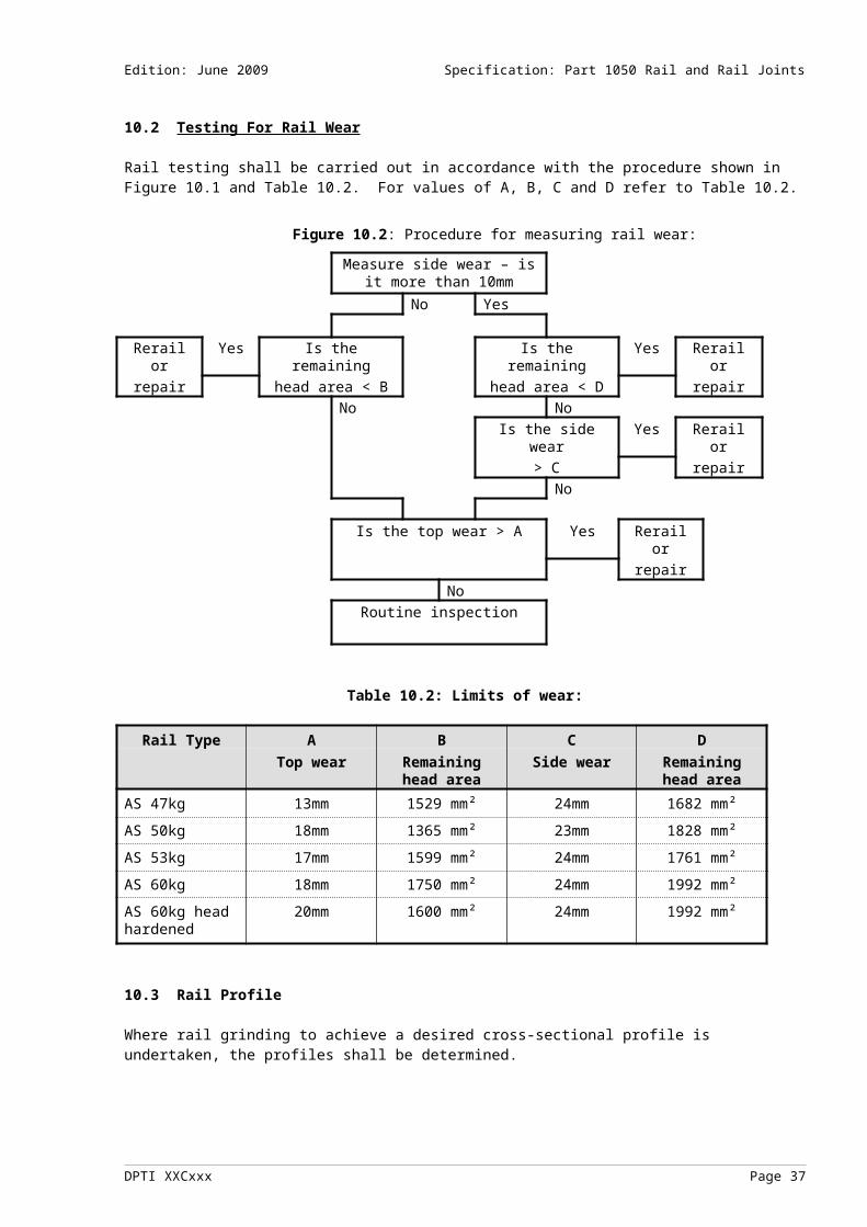
Edition: June 2009 Specification: Part 1050 Rail and Rail Joints
A2.18 WELD DEFECT (Head); Defect code: WA, WF, WT; Defect position: H
This is an internal defect that occurs within the head of the rail at welds joining rails. It usually starts from imperfections within the weld zone, for example lack of fusion or inclusions from the welding process.
Action shall be taken by removing the weld and then inserting a new section of rail or the use of a wide gap weld if no bolt holes exist. Visual detection is only possible after the defect has reached a surface.
Defect size Response time ActionLess than 5% (i.e. 10mm) None No action5-10% (10-20mm) 7 days Re-assess, plate, repair or remove10-30% (20-30mm) 1 day Re-assess, plate, repair or remove30–70% (30–40mm) 2 hours Speed restrict and re-assess every day, or
plate, or removeGreater than 70% (i.e. > 40mm) Immediate Speed restrict and re-assess every day, or
plate, or removeSurface Cracking [1] on rail head (visual - not confirmed by ultrasonics)
Immediate Speed restrict and re-assess every day, or plate, or remove
Broken Weld Immediate Pilot, or plate, or removeNote [1] Surface cracking may not be very deep but can only be confirmed by manual ultrasonics.
A2.19 WELD DEFECT (Web); Defect code: WA, WF, WT; Defect position: W
This is an internal defect that occurs within the web of the rail at welds joining rails. It usually starts from imperfections within the weld zone, for example lack of fusion or inclusions from the welding process.
Action shall be taken by removing the weld and then inserting a new section of rail or the use of a wide gap weld if no bolt holes exist. Visual detection is only possible after the defect has reached a surface.
Defect size Response time ActionLess than 25mm None No action25-50mm 30 days Re-assess, plate or remove50-75mm 1 day Speed restrict and re-assess daily, or plate, or removeGreater than 75mm 2 hours Speed restrict and re-assess daily, or plate, or removeBroken Weld Immediate Pilot or plate or remove
DPTI XXCxxx Page 37
Edition: June 2009 Specification: Part 1050 Rail and Rail Joints
A2.20 WELD DEFECT (Foot); Defect code: WA, WF, WT; Defect position: F
This is an internal defect that occurs within the foot of the rail at welds joining rails. It usually starts from imperfections within the weld zone, for example lack of fusion or inclusions from the welding process.
Action shall be taken by removing the weld and then inserting a new section of rail or the use of a wide gap weld if no bolt holes exist. Visual detection is only possible after the defect has reached a surface.
Defect size Response time ActionLess than 15mm width and full height of foot
14 days Re-assess or plate or remove
15 - 35mm width (if on edge use 10 – 35mm)
1 day Speed restrict and re-assess every day, or remove
Greater than 35mm width Immediate Speed restrict and re-assess every day, or removeBroken Weld Immediate Pilot or plate or remove
A2.21 WELD DEFECT: REPAIRS OF SURFACE DEFECTS (surface e.g. gas hole, hot tear, shrinkage, porosity); Defect code: WR; Defect position: H
This is a defect in the head of the rail that results from an aluminothermic or arc weld repair. Ultrasonic defects that occur are to be found in other defect classifications.
Alignment defects may be corrected by grinding, surface repair or replacement with a closure rail.
Alternatively, action shall be taken by removing the weld and then inserting a new section of rail or the use of a wide gap weld if no bolt holes exist. Visual detection is only possible after the defect has reached a surface.
Defect size Response time ActionLess than 3% (i.e. 10mm) None No action3-7% (10-15mm) 7 days Re-assess, plate, repair or remove7-10% (15-20mm) 7 days Re-assess, plate, repair or remove10-20% (20-30mm) 1 day Speed restrict, plate, repair or removeGreater than 20% (i.e. > 30mm) Immediate Speed restrict, plate, repair or removeGreater than 20% and surface cracking on rail head
Immediate Speed restrict, plate, repair or remove
Broken Weld Immediate Pilot or plate, or remove
A2.22 MILL DEFECT; Defect code: MD; Defect position: Z
Deformations, cavities, seams or foreign material found in the head, web or foot of a rail. These defects are formed during manufacture. Further development depends on the type of defect, its position within the rail and loading of the rail. Surface defects may be visible but generally the defect is too small to be visible.
Action is not normally required until growth is detected, then the defect may be reclassified according to the nature of propagation or failure.
Defect size Response time ActionAny None The necessary action should be assessed by a competent worker
DPTI XXCxxx Page 38

Edition: June 2009 Specification: Part 1050 Rail and Rail Joints
A2.23 CORRODED RAIL; Defect code: CR; Defect position: Y
Corrosion of the metal on the foot or web of the rail will result in pits or cavities. Corrosion occurs in wet or damp areas and is usually a slow process. However the process will be greatly accelerated in situations where electric current passes through the rail, or where chemicals, for example acidic ground water or fertilisers are concentrated. Points of high stress from corrosion pitting or severe reduction in cross section may cause sudden failure. Excavation of ballast, bitumen etc. may be required to view the corroded rail.
Action requires replacement of the defective portion of rail.
Note: The necessary action should be assessed by a competent worker and shall include consideration of the location, extent and geometry of the corrosion. Refer also to Rail Surface below where corrosion impacts on the running surface of the rail.
Defect size Response time Action
Greater than 3mm section loss in web or foot
7 days Speed restrict until removed.
A2.24 MECHANICAL JOINT; Defect code: MJ; Defect position: X
This category refers to a rail where an unidentified ultrasonic response is received. Further information shall be provided to assist with visual inspection. The necessary repair should be determined by a competent worker.
Defect size Response time Action
Any 14 days Remove plates and assess
A2.25 RAIL SURFACE; Defect code: RS; Defect position: H
This category refers to a rail surface condition, for example rolling contact fatigue, corrugation, checking and rust, which does not permit an adequate ultrasonic test.Note: The necessary action should be assessed by a competent worker and include consideration of the location, extent and the ability to carry out ultrasonic testing of the rail affected.
Defect size Response time Action
Any 30 days Assess
A2.26 WHEEL BURN; Defect code: WB; Defect position: H
A scar on the running surface of the rail caused by intense friction heating from slipping driving wheels. The flowed metal may chip out and thermal cracks may develop into a transverse defect.
Note [1] – Wheel burns should generally be removed by grinding and/or surface repair welding and in severe cases by removal of the rail and insertion of a closure rail. Grinding should remove all heat affected steel. Wheel burns can vary significantly in severity. The severity will determine the response time and action necessary. The geometry of the wheel burn can result in severe dynamic loading of the track and a resulting increased rate of deterioration of the track structure in general. Where defects are not removed from track, a defect management plan should be put in place to monitor the wheel burn for TWH defects and general track deterioration.
Defect size Response time Action
Any See note [1] Check for TWH
DPTI XXCxxx Page 39

Edition: June 2009 Specification: Part 1050 Rail and Rail Joints
A2.27 NOTCHES; Defect code: NO; Defect position: Z
Mechanical damage to the head, web or foot of the rail which results in a point of high stress. May be caused by hammer blows, equipment contact, damaged wheels, overdriven fastenings, local corrosion, wear from plates or fastenings, saw cutting or gas cutting. Defects are visible.
Action - Defects may be plated or cut out and the rail welded or replaced by a closure rail. The determination of the required action requires assessment of the defect by a competent worker and shall include consideration of the location, extent and geometry of the notch or cut. Isolated dented or bruised rail, for example due to a hammer blow, may not generally require removal.
Defect size Response time Action
Any 30 days Assess
A2.28 BROKEN FOOT; Defect code: BF; Defect position: F
A progressive fracture in the foot of the rail with a vertical split. The separation is substantially longitudinal but usually turns out to the edge of the foot. These separations are often called half moon breaks. The cause is usually improper bearing on plates, damage to rail foot or a seam, segregation or inclusion. The crack is usually visible and may be accentuated by oxidation (bleeding).
Action - Defects may be cut out and replaced by a closure rail.
Defect size Response time Action
All Immediate Pilot or speed restrict and re-assess daily, plate, or remove
A2.29 BROKEN RAIL; Defect code: BR; Defect position: Z
This classification generally refers to a square or angular, sudden rupture, transverse separation of the head, web and foot of the rail. This type of failure usually occurs in very cold weather and is often caused by concentrated loadings (overstressing) from rolling stock or track maintenance operations. If any sign of a defect is present, the break shall be reclassified according to the type of defect.
Gap in the running rail - The following limits apply to the movement of traffic over a gap (or break) in the running rail:
Gap < 30mm Operation of trains at a reduced speed appropriate to the assessed track conditions
Gap > 30mm and < 100mm Pilot trains across gapGap > 100mm Stop traffic
Assessment of the track condition by a competent worker should include consideration of the track alignment, sleepers, fastenings, track geometry and support either side of the gap (or break). The need for temporary plating of a gap (or break) should also be determined. In the case of a break, the nature of the rail break should be considered in the assessment. Note: imperfections that may have damaged rolling stock should be advised to the Traffic Control office.
Action - Defects may be plated or cut out and the rail welded (subject to compliance with minimum distance requirements to bolt holes) or replace by a closure rail.
Defect size Response time Action
All Immediate Pilot or speed restrict and plate or remove
DPTI XXCxxx Page 40

Edition: June 2009 Specification: Part 1050 Rail and Rail Joints
A2.30 OXY- CUT RAIL OR BOLT HOLE; Defect code: OC; Defect position: Z or W
Rails and bolt holes that have been oxy-cut shall be considered as defective. They shall only be used in an emergency and shall be removed as soon as the emergency has passed.
Defect size Response time ActionOxy-cut rails Immediate Speed restrict to 20km/hr and re-assess daily or removeOxy-cut bolt holes
Immediate Speed restrict to 20km/hr and re-assess daily or remove
A2.31 UNDERLENGTH RAILS; Defect code: UR; Defect position: Z
Rails that are shorter than the minimum length shown in CP-TS-960 (Track support systems) for each configuration shall require the track at that location to be considered as conforming to the configuration to which the rail length corresponds. Where underlength rails are shorter than those corresponding to any track configuration they shall be considered as defective.
Defect size Response time
Action
Length between the absolute minimum shown in table 2.1 and the length shown in CP-TS-960 (Track support systems)
90 days Restore to standard configuration
Length less than the absolute limit shown in Table 2.4
Immediate Speed restrict to 30km/hr and restore to standard configuration within 90 days
A2.32 UNCLASSIFIED DEFECT;
The necessary repair should be determined by a competent worker.
____________
DPTI XXCxxx Page 41

____________
DPTI XXCxxx Page 42