circabc.europa.eu · Web view"eCall log file" means any record of an automatic or manual eCall...
59
EN EN EUROPEAN COM M ISSION Brussels, XXX […] (2015)XXX draft CO M M ISSIO N DELEG ATED REG U L A TIO N (EU )… /... ofXXX supplem enting and am ending R egulation (EU )2015/758 ofthe E uropean Parliam ent and ofthe C ouncilconcerning type-approvalrequirem entsfor 112-based eC allin- vehiclesystem s (Textw ith EEA relevance)
Transcript of circabc.europa.eu · Web view"eCall log file" means any record of an automatic or manual eCall...
EN EN
EUROPEAN COMMISSION
Brussels, XXX […](2015) XXX draft
COMMISSION DELEGATED REGULATION (EU) …/...
of XXX
supplementing and amending Regulation (EU) 2015/758 of the European Parliament and of the Council concerning type-approval requirements for 112-based eCall in-
vehicle systems
(Text with EEA relevance)
DISCUSSION PAPERDRAFT CONCEPT version 03 of 03.12.2015
This document does not represent an official position of the European Commission. It is a tool to explore the views of interested parties. The suggestions contained in this document do not prejudge the form and content of any possible future proposal by the European Commission.
COMMISSION DELEGATED REGULATION (EU) …/...
of XXX
supplementing and amending Regulation (EU) 2015/758 of the European Parliament and of the Council concerning type-approval requirements for 112-based eCall in-
vehicle systems
(Text with EEA relevance)
THE EUROPEAN COMMISSION,
Having regard to the Treaty on the Functioning of the European Union,
Having regard to Regulation (EU) No 2015/7581, and in particular Article 2(2), Article 5(8) and (9) and Article 6(12) thereof,
Whereas:
(1) This Regulation aims to set out the technical requirements and test procedures for the type-approval of 112-based eCall in-vehicle systems.
(2) …..
1 OJ L 123, 19.5.2015, p. 77.
EN 2 EN
HAS ADOPTED THIS REGULATION:
Article 1
Subject matter
This Regulation establishes detailed technical requirements and test procedures for the EC type-approval of vehicles in respect of their 112-based eCall in-vehicle systems, and for the approval of 112-based eCall in-vehicle systems, as components [andor separate technical units] in accordance with Regulation (EU) No 2015/758.
Article 2
Scope
1. This Regulation applies to motor vehicles of categories M1 and N1 as defined in points 1.1.1 and 1.2.1 of Part A of Annex II to Directive 2007/46/EC, as well as to 112-based eCall in-vehicle systems[, components and separate technical units] intended for fitment to those vehicles, with the exception of the following:
(1) vehicles produced in small series approved pursuant to Articles 22 and 23 of Directive 2007/46/EC;
(2) vehicles approved pursuant to Article 24 of Directive 2007/46/EC;
(3) vehicles which for technical reasons cannot be equipped with an appropriate eCall triggering mechanism, as determined in accordance with Article 2(2) of Regulation (EU) No 2015/758 and inserted in the list to be established in Annex IX to this Regulation. The decision to insert a type of vehicle in the list shall be made by the Commission on the basis of cost/benefit assessment taking into account all relevant safety and technical aspects.
2. In case of multi-stage approval of special purpose vehicles, as defined in points 5.1 and 5.5 of part A of Annex II of Directive 2007/46/EC, the approval granted at a previous stage in respect of the 112-based eCall in-vehicle system of the base vehicle shall remain valid provided that the 112-based eCall in-vehicle system and its sensors are not changed and the conversion of the vehicle structure do not affect the functioning of this system.
Article 3
Definitions
For the purposes of this Regulation, the definitions in Article 3 of Regulation (EU) No 2015/758 shall apply. The following definitions shall also apply:
1. "representative arrangement of parts" means all parts required by the eCall in-vehicle system to successfully populate and transmit the minimum set of data (MSD) in an eCall, which shall include the control module (ECU), the power source, the mobile network communication module, the GNSS receiver, the external GNSS antenna, the connectors and the mounting brackets;
EN 3 EN
2. "eCall log file" means any record of an automatic or manual eCall activation which is stored within the internal memory of the eCall in-vehicle system, including the timestamp associated with that event;
3.[2.] “Global Navigation Satellite System” (GNSS) means a satellite based system that is used to pinpoint the location, speed and time of a user's receiver in any point of the Earth surface, water areas, air space, and in the near-Earth space environment. (e.g.: Galileo);
4. “Satellite-Based Augmentation System” (SBAS) means a system ensuring the correction of local errors of GNSS systems via a network of ground-based stations. (e.g.: EGNOS);
5. “ cold start mode” means the condition of a GNSS receiver when position, velocity, time, almanac and ephemeris data are not stored in the receiver, and therefore the navigation solution is to be calculated by means of a full sky search.
Article 4
Requirements and test procedures for EC type-approval of motor vehicles in respect of their 112-based eCall in-vehicle systems
In order to receive an EC vehicle type-approval in respect of the 112-based eCall in-vehicle system, the manufacturer shall demonstrate that the motor vehicle is subject to the tests and comply with the technical requirements set out in Annexes I to VIII to this Regulation.
Article 5
Requirements and test procedures for EC type-approval of 112-based eCall in-vehicle systems as components [or separate technical units]
In order the 112-based eCall in-vehicle system to receive an EC type-approval as system, component [or separate technical unit type-approval], the manufacturer shall demonstrate that thate system, component or separate technical unit is subject to the tests and comply with the requirements set out in Annexes I, IV, [VI] and VIII to this Regulation.
Article 6
Requirements and test procedures for EC type-approval of motor vehicles with regard to the 112-based eCall in-vehicle systems approved as components [or separate technical units]
When the motor vehicle is fitted with 112-based eCall in-vehicle system approved as a component [or a separate technical unit], the manufacturer shall demonstrate that, for the purposes of EC vehicle type-approval, the vehicle is subject to the tests and complies with the technical requirements set out in Annexes II, III, V, VI and VII to this Regulation.
EN 4 EN
[Article 6
Obligations of the Member States
[1.] With effect from 31 March 2018, national authorities shall refuse, on grounds relating to 112-based eCall in-vehicle system, to grant:
EC type-approval in respect of new types of vehicles on grounds relating to 112-based eCall in-vehicle system, where such vehicles do not comply with the requirements set out in this Regulation.;
EC type-approval in respect of eCall in-vehicle systems, components or separate technical units, where such systems, components or technical units do not comply with the requirements set out in this Regulation.]
[2.] Without prejudice to paragraph 1, and subject to the entry into force of the implementing measures adopted pursuant to Article 9 and Article 6(13) of Regulation (EU) No 2015/758, if a manufacturer so requests, national authorities mayshall not :
[3.] on grounds relating to 112-based eCall in-vehicle system, refuse to grant EC type-approval for a new types of vehicles, andorEC type-approval for an eCall in-vehicle system approved as, components or separate technical unit, where such vehicles and, systems, component or separate technical unit complyies with this Regulation.;
[(a)] prohibit registration, placing on the market or entry into service of a new vehicle or the sale and entry into service of an eCall in-vehicle system, component or separate technical unit, where such vehicle, system, component or separate technical unit complies with this Regulation.
Article 7
Amendment to Regulation (EU) No 2015/758
The standards referred to in Article 5(8) sub-paragraphs (a) to (d) of Regulation (EU) No 2015/758 shall be replaced by the following versions:
(a) EN 16072:2015 'Intelligent transport systems – eSafety – Pan-European eCall operating requirements';
(b) EN 16062:2015 'Intelligent transport systems – eSafety – eCall high level application requirements (HLAR)';
(c) EN 16454:2015 'Intelligent transport systems – ESafety – Ecall end to end conformance testing';
(d) EN 15722:2015 'Intelligent transport systems – eSafety – eCall minimum set of data (MSD)';
EN 5 EN
STOYANOVA Elitza (ENTR), 01/12/15,
Is the industry interested in voluntary TA before the date of application of the eCall Regulation? If not, this Article to be removed.

Article 8
Entry into force and application
This Regulation shall enter into force on the twentieth day following that of its publication in the Official Journal of the European Union.
It shall apply from 31 March 2018[, with the exception of Article 6(2), which shall apply from the date of entry into force of this Regulation].
This Regulation shall be binding in its entirety and directly applicable in all Member States.
Done at Brussels,
For the CommissionThe President
EN 6 EN
ANNEXES
Annex Number Annex title Page
I Technical requirements and procedure for testing the resistance of eCall systems to severe crashes (sled-based test) 7
II Full-scale impact test assessments 13
III Crash resistance of audio equipment 16
Addendum: Test Sentences 18
IV Co-existence of third party services (TPS) with the 112-based in-vehicle systems 22
V Automatic triggering mechanism 25
VI Technical requirements for compatibility of eCall in-vehicle systems with the positioning services provided by the Galileo and the EGNOS systems
26
VII In-vehicle system self-test 39
Table 1: Template of information for self-test 40
VIII Privacy and data protection requirements and testing procedures:
Part I: Procedure for verifying the lack of traceability of eCall in-vehicle systems 43
Part I: Procedure for verifying the length of time an eCall log file is stored by the eCall in-vehicle system 44
Part III: Procedure for verifying the automatic and continuous removal of data in the internal memory of eCall in-vehicle systems
45
Part IV: Procedure for verifying the non-exchange of personal data between eCall in-vehicle systems and third party services systems
46
IX List of exemptions under Article 2(3) 48
EN 7 EN

ANNEX ITechnical requirements and procedure for testing the resistance of eCall systems to
severe crashes (high-severity deceleration test)
1. Requirements
1.1. Performance requirements
1.1.1. The high-severity deceleration test of eCall in-vehicle systems, components or separate technical units, carried out in accordance with Paragraph 2, shall be considered satisfactory if the following requirements are demonstrated post-deceleration/acceleration event.
1.1.2. MSD emission and encoding: The eCall system shall be able to successfully transmit an MSD to a PSAP test point.
1.1.3. Incident time determination: The eCall system shall be able to determine an up-to-date timestamp for an eCall incident.
1.1.4. Position determination: The eCall system shall be able to determine accurately the up-to-date vehicle location.
1.1.5. Mobile network connectivity: The eCall system shall be able to connect to and transmit data via the mobile network.
2. Test procedure
2.1. Purpose of the high-severity deceleration test procedure
The purpose of this test is to verify the sustained functionality of the 112-based eCall system after being subjected to inertial loads which may occur during a severe vehicle crash.
[2.2.] The following tests shall be performed on a representative arrangement of parts (without a vehicle body) for the approval of vehicles, components or separate technical units.
2.1.1.[2.2.1.] A representative arrangement shall include all parts required by the eCall system to successfully populate and transmit the MSD in an eCall.
2.1.2.[2.2.2.] This shall include the control module and the power source and any other parts required to perform the manual test eCall.
2.1.3.[2.2.3.] This shall include external antennas for mobile communication and positioning.
[2.2.4.] The wiring harness may be represented only by the relevant connectors (connected to the tested components) and a length of wire. The length of the wiring harness and its eventual fixation can be decided by the manufacturer in agreement with the technical service so that it is at least representative for the different installation configurations of the eCall systemof the unsupported cable length.
EN 8 EN
2.2.[2.3.] Deceleration/acceleration procedure
2.2.1.[2.3.1.] The following conditions shall apply:
(a) The test shall be conducted at an ambient temperature of 20 ± 10 °C.
(b) At the beginning of the test, the power supply shall be charged sufficiently to allow performing the subsequent verification tests.
2.2.2.[2.3.2.] The tested parts shall be connected to the test fixture by the intended mountings provided for the purpose of attaching them to a vehicle.
2.2.3.[2.3.3.] If additional brackets or fixtures are used as part of the deceleration/acceleration facility, these shall provide a sufficiently rigid connection to the deceleration/acceleration facility to not affect the outcome of the test.
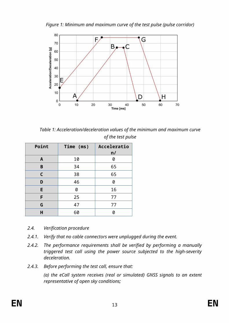
2.2.4.[2.3.4.] The eCall system shall be decelerated or accelerated in compliance with the pulse corridor that is specified in Table 1 and Figure 1. The acceleration/deceleration shall be measured at a rigid part of the deceleration/acceleration facility and filtered at CFC-60.
2.2.5.[2.3.5.] The test pulse shall be within the minimum and maximum values as specified in Table 1. The maximum velocity change ΔV shall be 70 km/h [+0/-2 km/h]. However, if with the agreement of the manufacturer, the test was performed at a higher acceleration or deceleration level, a higher ΔV and/or longer duration the test shall be considered satisfactory.
2.2.6.[2.3.6.] The eCall system shall be tested in a total of six orientations: The direction of acceleration/deceleration shall coincide with three axes perpendicular to each other (at least one being a main axis of the component design), each tested in positive and negative direction.
2.2.7.[2.3.7.] Different orientations may be tested simultaneously (i.e. during the same acceleration/deceleration event) by mounting more than one sample in perpendicular orientations to the acceleration/deceleration facility. If the orientations are tested individually, new samples may be used for each orientation.
2.2.8.[2.3.8.] Description of the test pulse
Figure 1: Minimum and maximum curve of the test pulse (pulse corridor)
EN 9 EN
Table 1: Acceleration/deceleration values of the minimum and maximum curve of the test pulse
Point Time (ms) Acceleration/ Deceleration (g)
A 10 0
B 34 65
C 38 65
D 46 0
E 0 16
F 25 77
G 47 77
H 60 0
2.3.[2.4.] Verification procedure
2.3.1.[2.4.1.] Verify that no cable connectors were unplugged during the event.
2.3.2.[2.4.2.] The performance requirements shall be verified by performing a manually triggered test call using the power source subjected to the high-severity deceleration.
2.3.3.[2.4.3.] Before performing the test call, ensure that:
(a) the eCall system receives (real or simulated) GNSS signals to an extent representative of open sky conditions;
(b) the eCall system has had sufficient time in a powered state to achieve a GNSS position fix;
(c) one of the connection procedures defined in Paragraph 2.7, as agreed between the technical service and the manufacturer, will be applied for any test call;
(d) the dedicated PSAP test point is available to receive an eCall emitted by the 112-based system;
(e) a false eCall to a genuine PSAP cannot be made over the live network; and
(f) if applicable, the TPS system is deactivated or will automatically switch to the 112-based system.
2.3.4.[2.4.4.] Perform a test call (push mode) by applying a manual trigger according to the instructions of the manufacturer.
2.3.5.[2.4.5.] Verify each of the following items:
(a) Verify that an MSD was received by the PSAP test point. This shall be verified by a record of the PSAP test point showing that an MSD emitted from the eCall system following the manual trigger was received and successfully decoded. If the MSD decoding failed at redundancy version MSD rv0 but was successful at a higher redundancy version or in robust modulator mode, as defined in ETSI/TS 126 267, this is acceptable..
EN 10 EN
(b) Verify that the MSD contained an up-to-date timestamp. This shall be verified by a test record showing that the timestamp contained in the MSD received by the PSAP test point does not deviate from the exact recorded time of the manual trigger activation by more than 60 seconds. The transmission may be repeated if the eCall system failed to achieve a GNSS position fix before the test.
(c) Verify that the MSD contained an accurate, up-to-date location. This shall be verified in accordance with the Vehicle Location Test Procedure as defined in Paragraph 2.5 by a test record showing that the deviation between IVS location and true location, d_IVS, is less than 150 metres and the confidence bit transmitted to the PSAP test point indicates 'position can be trusted’.
2.3.6.[2.4.6.] Clear down the test call using the appropriate PSAP test point command (e.g. hang up).
2.4.[2.5.] Positioning test procedure
2.4.1.[2.5.1.] The sustained functionality of the GNSS components shall be verified by comparing the location input and the location output of the system.
2.4.2.[2.5.2.] The ‘IVS location’ (φ IVS, λ IVS) shall be: The location contained in an MSD transmitted to a PSAP test point while the GNSS antenna is in open sky conditions (real or simulated).
2.4.3.[2.5.3.] The ‘true location’ (φ true, λ true) shall be:
(a) the actual location of the GNSS antenna (known location or determined with another means than the eCall system), when using real GNSS signals; or
(b) the simulated location, when using simulated GNSS signals.
2.4.4.[2.5.4.] The deviation between IVS location and true location, d IVS, shall be calculated using the following equations:
Δφ=φIVS−φtrue
Δλ= λIVS−λ true
φm=φ IVS+φtrue
2
d IVS=R√( Δφ)2+(cos (φm) Δλ)2
where:
Δφ: Difference in latitude (in radian)
Δλ: Difference in longitude (in radian)
Note: 1 °= π180
rad; 1mas = 4.8481368∙10−9 rad
φm: Mean latitude (in unit suitable for the cosine calculation)
R: Radius of the earth (mean) = 6,371,009 metres
EN 11 EN
2.4.5.[2.5.5.] The positioning test procedure may be repeated if the eCall system failed to achieve a GNSS position fix before the test.
2.5.[2.6.] Antenna test procedure
2.5.1.[2.6.1.] If the connection procedure applied for the test call did not make use of over-the-air data transmission, the sustained functionality of the mobile network antenna shall be verified by checking the antenna tuning status after the deceleration event according to the following procedure.
2.5.2.[2.6.2.] If the positioning test procedure did not make use of over-the-air GNSS signal transmission, the sustained functionality of the GNSS antenna shall be verified by checking the antenna tuning status after the deceleration event according to the following procedure.
2.5.3.[2.6.3.] Measure the voltage standing wave ratio, VSWR, of the external mobile network antenna or the GNSS antenna after the deceleration event at a frequency within the antenna’s specified frequency band.
2.5.3.1.[2.6.3.1.] The measurement shall be performed with a power meter, antenna analyser or SWR meter as close as possible to the antenna feed point.
2.5.3.2.[2.6.3.2.] If a power meter is used, VSWR shall be calculated using the following equation:
VSWR= √P f +√P r
√Pf −√Pr
where:Pf : Forward measured power
Pr: Reverse/reflected measured power
2.5.4.[2.6.4.] Verify that VSWR satisfies the specifications prescribed by the manufacturer for new antennas.
2.6.[2.7.] Connection procedures
2.6.1.[2.7.1.] Simulated Mobile Network Procedure
2.6.1.1.[2.7.1.1.] It shall be ensured that a TS12 call emitted by the 112-based system will be performed over-the-air via a non-public (i.e. simulated) mobile network and routed to the dedicated PSAP test point.
2.6.1.2.[2.7.1.2.] The dedicated PSAP test point during the test procedures shall be a PSAP simulator under the control of the technical service, compliant with the applicable EN standards and certified in accordance with EN 16454. It shall be equipped with an audio interface to allow voice communication tests.
2.6.1.3.[2.7.1.3.] If applicable, it shall be ensured that a TS11 call emitted by the TPS system will be performed over-the-air via a non-public (i.e. simulated) mobile network and routed to the TPSP test point.
EN 12 EN
2.6.1.4.[2.7.1.4.] The TPSP test point shall be a dedicated TPSP answering point simulator under the control of the technical service or a genuine TPSP answering point (permission by TPSP required).
[2.7.1.5.] Good mMobile network coverage of at least -99 dBm or equivalent is recommended for this procedure.
2.6.2.[2.7.2.] Public Mobile Network Procedure
2.6.2.1.[2.7.2.1.] It shall be ensured that a TS11 call to a long number will be emitted by the 112-based system (instead of a TS12 call) and will be performed over-the-air via a public mobile network and routed to the dedicated PSAP test point.
2.6.2.2.[2.7.2.2.] The dedicated PSAP test point during the test procedures shall be a PSAP simulator under the control of the technical service, compliant with the applicable EN standards and certified in accordance with EN 16454. It shall be equipped with an audio interface to allow voice communication tests.
2.6.2.3.[2.7.2.3.] If applicable, it shall be ensured that a TS11 call emitted by the TPS system will be performed over-the-air via a public mobile network and routed to the TPSP test point.
2.6.2.4.[2.7.2.4.] The TPSP test point shall be a dedicated TPSP answering point simulator under the control of the technical service or a genuine TPSP answering point (permission by TPSP required).
[2.7.2.5.] Good mMobile network coverage of at least -99 dBm or equivalent is recommended for this procedure.
2.6.3.[2.7.3.] Wired Transmission Procedure
2.6.3.1.[2.7.3.1.] It shall be ensured that a TS12 call emitted by the 112-based system will only be performed via a wired connection with a dedicated network simulator (bypassing any mobile network antenna) and routed to the dedicated PSAP test point.
2.6.3.2.[2.7.3.2.] The dedicated PSAP test point during the test procedures shall be a PSAP simulator under the control of the technical service, compliant with the applicable EN standards and certified in accordance with EN 16454. It shall be equipped with an audio interface to allow voice communication tests.
2.6.3.3.[2.7.3.3.] If applicable, it shall be ensured that a TS11 call emitted by the TPS system will be performed via a wired connection with a dedicated network simulator (bypassing any mobile network antenna) and routed to the dedicated TPSP test point.
2.6.3.4.[2.7.3.4.] The TPSP test point shall be a dedicated TPSP answering point simulator under the control of the technical service or a genuine TPSP answering point (permission by TPSP required).
EN 13 EN
ANNEX II
Full-scale impact test assessments
1. Requirements
1.1. Performance requirements
1.1.1. The full-scale impact assessments of vehicles with eCall in-vehicle systems installed, carried out in accordance with Paragraph 2, shall be considered satisfactory if the following requirements are demonstrated post-impact.
1.1.2. Automatic triggering: The eCall system shall automatically initiate an eCall after an impact in accordance with UN Regulation No. 94 (Annex 3) or UN Regulation No. 95 (Annex 4), as applicable.
1.1.3. Manual triggering: The eCall system shall allow manual triggering of an eCall by vehicle occupants.
1.1.4. Call status indication: The eCall system shall inform the occupants about the current status of the eCall (status indicator) using a visual and/or audible signal.
1.1.5. MSD emission and encoding: The eCall system shall be able to successfully transmit an MSD to a PSAP test point via the mobile network.
1.1.6. Vehicle-specific data determination: The eCall system shall be able to populate accurately the mandatory vehicle-specific data fields of the MSD.
1.1.7. Position determination: The eCall system shall be able to determine accurately the up-to-date vehicle location.
2. Test procedure
2.1. Purpose of the full-scale test procedure
The purpose of this test is to verify the automatic triggering function and the sustained functionality of the 112-based eCall in-vehicle system in vehicles that are subjected to a frontal impact or a side impact.
[2.2.] The following tests shall be performed on a vehicle with an eCall in-vehicle system installed for the approval of vehicles.
2.2.[2.3.] Impact test procedure
2.2.1.[2.3.1.] An impact test shall be carried out in accordance with the tests defined UN Regulation No. 94, Annex 3 for frontal impact or UN Regulation No. 95, Annex 4 for side impact.
2.2.2.[2.3.2.] The test conditions defined in UN Regulation No. 94 or UN Regulation No. 95 shall apply.
2.2.3.[2.3.3.] Before performing the impact tests, ensure that:
EN 14 EN
(a) the in-vehicle power source, if installed for the test, is charged sufficiently according to the specifications of the manufacturer at the beginning of the test to allow performing the subsequent verification tests;
(b) the automatic eCall is enabled and armed and that the vehicle ignition or master control switch is activated;
(c) one of the connection procedures defined in Paragraph 2.7, as agreed between the technical service and the manufacturer, will be applied for any test call;
(d) the dedicated PSAP test point is available to receive an eCall emitted by the 112-based system;
(e) a false eCall to a genuine PSAP cannot be made over the live network; and
(f) if applicable, the TPS system is deactivated or will automatically switch to the 112-based system.
2.3.[2.4.] Verification procedure
2.3.1.[2.4.1.] The performance requirements shall be verified by performing two test calls from the vehicle after the impact using the 112-based eCall in-vehicle system: An automatically triggered eCall following the impact test and a subsequent manually triggered eCall.
2.3.2.[2.4.2.] Perform a test call (push mode) by applying an automatic trigger (impact event) or a manual trigger (in-vehicle HMI), as applicable.
2.3.3.[2.4.3.] Verify each of the following items in at least one of the test calls:
(a) Verify that an eCall was triggered automatically by the full-scale impact event. This shall be verified by a record of the PSAP test point showing that it received an eCall initiation signal following the impact event and that the MSD control indicator was set to ‘automatically initiated eCall’.
(b) Verify that an eCall was triggered manually. This shall be verified by a record of the PSAP test point showing that it received an eCall initiation signal following the manual trigger application and that the MSD control indicator was set to ‘manually initiated eCall’.
(c) Verify that the eCall status indicator indicated an eCall sequence following the automatic or manual trigger. This shall be verified by a record of a test engineer showing that an indication sequence was performed on all sensory channels specified in the manufacturer’s documentation (visual and/or audible).
(d) Verify that an MSD was received by the PSAP test point. This shall be verified by a record of the PSAP test point showing that an MSD emitted from the vehicle following the automatic or manual trigger was received and successfully decoded. If the MSD decoding failed at redundancy version MSD rv0 but was successful at a higher redundancy version or in robust modulator mode, as defined in ETSI/TS 126 267, this is acceptable..
(e) Verify that the MSD contained accurate vehicle-specific data. This shall be verified by a record of the PSAP test point showing that the information transmitted in the fields regarding vehicle type, vehicle identification number (VIN) and vehicle
EN 15 EN
propulsion storage type does not deviate from the information specified in the type-approval application.
(f) Verify that the MSD contained an accurate, up-to-date location. This shall be verified in accordance with the Vehicle Location Test Procedure as defined in Paragraph 2.5 of Annex I to this Regulation by a test record showing that the deviation between IVS location and true location, d_IVS, is less than 150 metres and the confidence bit transmitted to the PSAP test point indicates 'position can be trusted’. If no GNSS signals are available at the impact test location, the vehicle can be moved to an appropriate location before performing the test call.
2.3.4.[2.4.4.] Clear down the test call using the appropriate PSAP test point command (e.g. hang up).
2.3.5.[2.4.5.] If the automatic test call could not be performed successfully due to vehicle-external factors, it shall be permissible to verify the automatic trigger following the impact via the internal record transaction function of the in-vehicle system. This register shall be capable to store received trigger signals in non-volatile memory. The test engineer shall have access to the data stored in the in-vehicle system and shall verify that no record of automatic trigger signal is stored before the impact event and that a record of an automatic trigger signal is stored after the impact event.
2.3.6.[2.4.6.] If the test call was performed with the vehicle connected to an off-vehicle power supply (in cases where the impact test was carried out with the standard vehicle power supply not installed), verify that the on-board electrical system feeding the eCall in-vehicle system remained intact. This shall be verified by a record of a test engineer confirming a successful check of the integrity of the on-board electrical system including the dummy in-vehicle power source (visual inspection for mechanical damage to either the battery mounting bracket or battery structure) and the connections via its terminals.
2.4.[2.5.] Positioning test procedure
The positioning test procedure defined in paragraph 2.5 of Annex I to this Regulation shall apply.
2.5.[2.6.] Antenna test procedure
[2.6.1.] If the connection procedure applied for the test call did not make use of over-the-air data transmission (paragraph 2.7.3 of Annex I to this Regulation), the sustained functionality of the mobile network antenna shall be verified by checking the antenna tuning status after the full-scale impact test according to the procedureThe antenna test procedure is identical to the procedure defined in paragraph 2.6 of Annex I to this Regulation shall apply.
2.5.1.[2.6.2.] Verify additionally that no wire breakage or short-circuit of the antenna feed line occurred by checking the electrical resistance between the end points of the wire and between the wire and vehicle ground.
2.6.[2.7.] Connection procedures
EN 16 EN
The connection procedures defined in paragraph 2.7 of Annex I to this Regulation shall apply.
EN 17 EN
ANNEX III
Crash resistance of audio equipment
1. Requirements 1.1. Performance requirements
1.1.1. The assessment of the crash resistance of the eCall audio equipment of vehicles with eCall in-vehicle systems installed, carried out in accordance with Paragraph 2, shall be considered satisfactory if the following requirements are demonstrated post-impact.
1.1.2. Reconnection of audio equipment: The eCall system shall reconnect the loudspeaker(s) and microphone(s) after being disconnected during an eCall for MSD transmission.
1.1.3. Voice communication: The eCall system shall allow hands-free voice communication (send and receive direction) of sufficient intelligibility between vehicle occupants and an operator.
2. Test procedure
2.1. Purpose of the audio equipment crash resistance test procedure
The purpose of this test is to verify that loudspeaker(s) and microphone(s) are successfully reconnected after being disconnected for MSD transmission and that the audio equipment remained functional after the vehicle has been subjected to a frontal impact or side impact.
2.2. The following verification test shall be performed on a vehicle with eCall in-vehicle systems installed that has been subjected to a full-scale impact according to Regulation No. 94, Annex 3 for frontal impact or UN Regulation No. 95, Annex 4 for side impact.
2.3. Overview of test procedure
2.3.1. The sustained functionality of the audio equipment shall be verified by performing a manually triggered test call after the impact test and using the voice communication channel between the vehicle and the PSAP test point.
2.3.2. Two test engineers, positioned in the vehicle (near-end tester) and at the PSAP test point (far-end tester) respectively, successively transmit (read and listen) pre-defined, phonetically balanced sentences in single talk mode.
2.3.3. The testers are required to assess whether they were able to understand the meaning of the transmission in the send and receive directions.
2.4. Arrangement of testers
EN 18 EN
2.4.1. The test shall be performed in a quiet environment, with a background noise level of not more than 50 dB(A) and that is free from any noise sources that might otherwise disrupt the tests.
2.4.2. The near-end tester shall be positioned so that his head is close to a normal seating position on the driver’s seat of the impacted vehicle. The tester shall use the in-vehicle audio equipment in the original arrangement.
2.4.3. The far-end tester shall be positioned away from the vehicle with sufficient separation so that speech in normal loudness from one tester cannot be understood without any aids by the other tester.
2.5. Test setup
2.5.1. Before performing the test call, ensure that:
(a) one of the connection procedures defined in Paragraph 2.7 of Annex I to this Regulation, as agreed between technical service and manufacturer, will be applied for any test call;
(b) the dedicated PSAP test point is available to receive an eCall emitted by the 112-based system;
(c) a false eCall to a genuine PSAP cannot be made over the live network;
(d) if applicable, the TPS system is deactivated or will automatically switch to the 112-based system; and
(e) the vehicle ignition or master control switch is activated.
2.5.2. Where it is possible to adapt the volume setting, the maximum volume control setting in send and receive direction at the near-end and at the far-end shall be chosen. The volume control settings at the far-end may be decreased during the test if required for better intelligibility.
2.5.3. If possible, no mobile networks that have an influence on the hands-free performance (e.g. echo, AGC, noise reduction, etc.) should be chosen for the connection. For simulated networks, if possible, DTX shall be switched off, the full rate codec shall be used (for GSM standard) and the highest bit rate of 12.2 kbit/s shall be used (for AMR codecs).
2.6. Test call
2.6.1. Perform a test call (push mode) by applying a manual trigger via the in-vehicle HMI and wait until the loudspeaker(s) and microphone(s) are reconnected for voice communication after completed MSD transmission.
2.6.2. Exchange of test messages
2.6.2.1. Receive direction
2.6.2.1.1. The far-end tester shall select and read one sentence pair of the list provided in the Appendix. The tester shall read the sentences in a normal volume as used in phone calls.
2.6.2.1.2. The near-end tester shall assess whether the voice transmission in the receive direction was intelligible: The test in receive direction is passed if the near-end
EN 19 EN
tester, resting in his original seating position, was able, with any feasible effort, to understand the full meaning of the transmission.
2.6.2.1.3. If required for the assessment, the near-end tester can request from the far-end tester to transmit additional sentence pairs.
2.6.2.2. Send direction
2.6.2.2.1. The near-end tester shall select and, resting in his original seating position, read one sentence pair of the list provided in the Appendix. The tester shall read the sentences in a normal volume as used in phone calls.
2.6.2.2.2. The far-end tester shall assess whether the voice transmission in the send direction was intelligible: The test in send direction is passed if the far-end tester was able, with any feasible effort, to understand the full meaning of the transmission.
2.6.2.2.3. If required for the assessment, the far-end tester can request from the near-end tester to transmit additional sentence pairs.
2.6.3. Clear down the test call using the appropriate PSAP test point command (e.g. hang up).
2.6.4. If the requirements cannot be fulfilled due to impairments introduced by the PSAP test point or the transmission medium, the test call may be repeated, if required in an adapted test setup.
2.7. Connection procedures
2.7.1. The connection procedures defined in paragraph 2.7 of Annex I to this Regulation shall apply.
Appendix
Test sentences
1. The following test sentence pairs, as defined in ITU-T P.501, Annex B, shall be used for the exchange of test messages in the send and receive directions.
2. Test sentence pairs in the language most commonly spoken by the testers shall be selected from the list below. If the testers are not familiar with any of the languages, alternative sentences in a familiar language, preferably phonetically balanced, shall be used.
3. Test sentence pairs
3.1. Dutch
(a) Dit produkt kent nauwelijks concurrentie.
Hij kende zijn grens niet.
(b) Ik zal iets van mijn carriere vertellen.
Zijn auto was alweer kapot.
EN 20 EN
(c) Zij kunnen de besluiten nehmen.
De meeste mensen hadden het wel door.
(d) Ik zou liever gaan lopen.
Willem gaat telkens naar buiten.
3.2. English
(a) These days a chicken leg is a rare dish.
The hogs were fed with chopped corn and garbage.
(b) Rice is often served in round bowls.
A large size in stockings is hard to sell.
(c) The juice of lemons makes fine punch.
Four hours of steady work faced us.
(d) The birch canoe slid on smooth planks.
Glue the sheet to the dark blue background.
3.3. Finnish
(a) Ole ääneti tai sano sellaista, joka on parempaa kuin vaikeneminen.
Suuret sydämet ovat kuin valtameret, ne eivät koskaan jäädy.
(b) Jos olet vasara, lyö kovaa. Jos olet naula pidä pääsi pystyssä.
Onni tulee eläen, ei ostaen.
(c) Rakkaus ei omista mitään, eikä kukaan voi sitä omistaa.
Naisen mieli on puhtaampi, hän vaihtaa sitä useammin.
(d) Sydämellä on syynsä, joita järki ei tunne.
On opittava kärsimään voidakseen elää.
3.4. French
(a) On entend les gazouillis d'un oiseau dans le jardin.
La barque du pêcheur a été emportée par une tempête.
(b) Le client s'attend à ce que vous fassiez une réduction.
Chaque fois que je me lève ma plaie me tire.
(c) Vous avez du plaisir à jouer avec ceux qui ont un bon caractère.
Le chevrier a corné pour rassembler ses moutons.
(d) Ma mère et moi faisons de courtes promenades.
La poupée fait la joie de cette très jeune fille.
EN 21 EN
3.5. German
(a) Zarter Blumenduft erfüllt den Saal.
Wisch den Tisch doch später ab.
(b) Sekunden entscheiden über Leben.
Flieder lockt nicht nur die Bienen.
(c) Gegen Dummheit ist kein Kraut gewachsen.
Alles wurde wieder abgesagt.
(d) Überquere die Strasse vorsichtig.
Die drei Männer sind begeistert.
3.6. Italian
(a) Non bisogna credere che sia vero tutto quello che dice la gente. Tu non conosci ancora gli uomini, non conosci il mondo.
Dopo tanto tempo non ricordo più dove ho messo quella bella foto, ma se aspetti un po' la cerco e te la prendo.
(b) Questo tormento durerà ancora qualche ora. Forse un giorno poi tutto finirà e tu potrai tornare a casa nella tua terra.
Lucio era certo che sarebbe diventato una persona importante, un uomo politico o magari un ministro. Aveva a cuore il bene della società.
(c) Non bisogna credere che sia vero tutto quello che dice la gente tu non conosci ancora gli uomini, non conosci il mondo.
Dopo tanto tempo non ricordo più dove ho messo quella bella foto ma se aspetti un po' la cerco e te la prendo.
(d) Questo tormento durerà ancora qualche ora. Forse un giorno poi tutto finirà e tu potrai tornare a casa nella tua terra.
Lucio era certo che sarebbe diventato una persona importante, un uomo politico o magari un ministro, aveva a cuore il bene della società.
3.7. Polish
(a) Pielęgniarki były cierpliwe.
Przebiegał szybko przez ulicę.
(b) Ona była jego sekretarką od lat.
Dzieci często płaczą kiedy są głodne.
(c) On był czarującą osobą.
Lato wreszcie nadeszło.
(d) Większość dróg było niezmiernie zatłoczonych.
Mamy bardzo entuzjastyczny zespół.
EN 22 EN
3.8. Spanish
(a) No arroje basura a la calle.
Ellos quieren dos manzanas rojas.
(b) No cocinaban tan bien.
Mi afeitadora afeita al ras.
(c) Vé y siéntate en la cama.
El libro trata sobre trampas.
(d) El trapeador se puso amarillo.
El fuego consumió el papel.
EN 23 EN
ANNEX IV
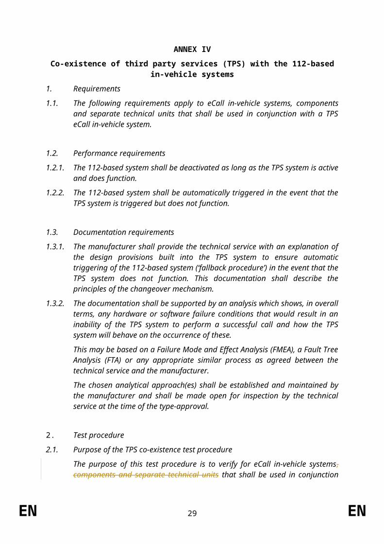
Co-existence of third party services (TPS) with the 112-based in-vehicle systems
1. Requirements
1.1. The following requirements apply to eCall in-vehicle systems, components and separate technical units that shall be used in conjunction with a TPS eCall in-vehicle system.
1.2. Performance requirements
1.2.1. The 112-based system shall be deactivated as long as the TPS system is active and does function.
1.2.2. The 112-based system shall be automatically triggered in the event that the TPS system is triggered but does not function.
1.3. Documentation requirements
1.3.1. The manufacturer shall provide the technical service with an explanation of the design provisions built into the TPS system to ensure automatic triggering of the 112-based system (‘fallback procedure’) in the event that the TPS system does not function. This documentation shall describe the principles of the changeover mechanism.
1.3.2. The documentation shall be supported by an analysis which shows, in overall terms, any hardware or software failure conditions that would result in an inability of the TPS system to perform a successful call and how the TPS system will behave on the occurrence of these.
This may be based on a Failure Mode and Effect Analysis (FMEA), a Fault Tree Analysis (FTA) or any appropriate similar process as agreed between the technical service and the manufacturer.
The chosen analytical approach(es) shall be established and maintained by the manufacturer and shall be made open for inspection by the technical service at the time of the type-approval.
2. Test procedure
2.1. Purpose of the TPS co-existence test procedure
The purpose of this test procedure is to verify for eCall in-vehicle systems, components and separate technical units that shall be used in conjunction with a TPS eCall in-vehicle system, that there is only one system active at a time and that the 112-based system is triggered automatically in the event that the TPS system does not function.
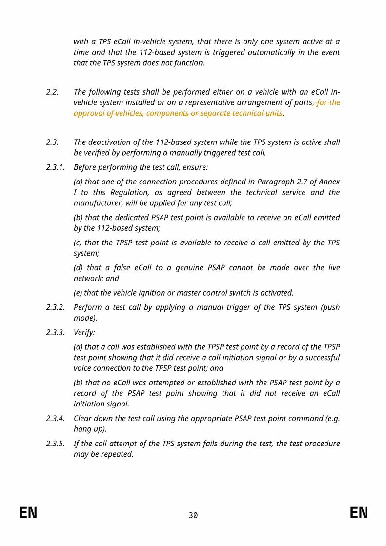
[2.2.] The following tests shall be performed either on a vehicle with an eCall in-vehicle system installed or on a representative arrangement of parts, for the approval of vehicles, components or separate technical units.
EN 24 EN

2.2.[2.3.] The deactivation of the 112-based system while the TPS system is active shall be verified by performing a manually triggered test call.
2.2.1.[2.3.1.] Before performing the test call, ensure:
(a) that one of the connection procedures defined in Paragraph 2.7 of Annex I to this Regulation, as agreed between the technical service and the manufacturer, will be applied for any test call;
(b) that the dedicated PSAP test point is available to receive an eCall emitted by the 112-based system;
(c) that the TPSP test point is available to receive a call emitted by the TPS system;
(d) that a false eCall to a genuine PSAP cannot be made over the live network; and
(e) that the vehicle ignition or master control switch is activated.
2.2.2.[2.3.2.] Perform a test call by applying a manual trigger of the TPS system (push mode).
2.2.3.[2.3.3.] Verify:
(a) that a call was established with the TPSP test point by a record of the TPSP test point showing that it did receive a call initiation signal or by a successful voice connection to the TPSP test point; and
(b) that no eCall was attempted or established with the PSAP test point by a record of the PSAP test point showing that it did not receive an eCall initiation signal.
2.2.4.[2.3.4.] Clear down the test call using the appropriate PSAP test point command (e.g. hang up).
2.2.5.[2.3.5.] If the call attempt of the TPS system fails during the test, the test procedure may be repeated.
2.3.[2.4.] The fallback procedure shall be verified by performing a manually triggered test call to a dedicated PSAP test point in a condition where the TPS system does not function.
2.3.1.[2.4.1.] Modify the TPS system to simulate a failure, selected at the discretion of the type-approval authority, that shall result in a fallback procedure based on the documentation provided by the manufacturer.
2.3.2.[2.4.2.] Before performing the test call, ensure:
(a) that one of the connection procedures defined in Paragraph 2.7 of Annex I to this Regulation, as agreed between the technical service and the manufacturer, will be applied for any test call;
(b) that the dedicated PSAP test point is available to receive an eCall emitted by the 112-based system;
(c) that a false eCall to a genuine PSAP cannot be made over the live network; and
(d) that the vehicle ignition or master control switch is activated.
2.3.3.[2.4.3.] Perform a test call by applying a manual trigger of the TPS system (push mode).
EN 25 EN
2.3.4.[2.4.4.] Verify that an eCall was established by the 112-based system by a record of the PSAP test point showing that it did receive an eCall initiation signal.
2.3.5.[2.4.5.] Clear down the test call using the appropriate PSAP test point command (e.g. hang up).
2.4.[2.5.] Connection procedures
The connection procedures defined in paragraph 2.7 of Annex I to this Regulation shall apply.
EN 26 EN
ANNEX V
Automatic triggering mechanism
1. Requirements
1.1. The following requirements apply to vehicles with eCall in-vehicle systems installed.
1.2. Documentation requirements
1.2.1. The manufacturer shall provide a statement which affirms that the strategy chosen to trigger an automatic eCall ensures triggering also in accident configurations dissimilar from and/or of a lower severity than the collisions simulated in the applicable full-scale crash tests in UN Regulation No. 94 and UN Regulation No. 95.
1.2.2. The manufacturer shall choose the collision typology and severity and will demonstrate that it is significantly different than the full-scale crash tests.
1.2.3. The manufacturer shall provide the type-approval authority with an explanation and technical documentation which shows, in overall terms, how this is achieved.
1.2.3.1. Documentation that shows, to the satisfaction of the type-approval authority, that the activation of supplemental restraint systems, at the severity level chosen at the discretion of the manufacturer, also induces an automatic eCall shall be considered satisfactory.
1.2.3.2. Airbag control unit specification drawings, specification data notes, sensitivity drawings, relevant circuit diagrams or similar documents considered equivalent by the type-approval authority would be suitable means to demonstrate this connection.
1.2.3.3. The extended documentation package shall remain strictly confidential. It may be kept by the approval authority, or, at the discretion of the approval authority, may be retained by the manufacturer. In case the manufacturer retains the documentation package, that package shall be identified and dated by the approval authority once reviewed and approved. It shall be made available for inspection by the approval authority at the time of approval or at any time during the validity of the approval.
EN 27 EN

ANNEX VI
Technical requirements for compatibility of eCall in-vehicle systems with the positioning services provided by the Galileo and the EGNOS systems
1. Requirements
1.1. Compatibility requirements
1.1.1. The ’Galileo system compatibility’ shall be: the reception and processing of the signals from the Open Service of Galileo, using it in the computation of the final position.
1.1.2. The ’EGNOS system compatibility’ shall be: the reception of the corrections from the Open Service of EGNOS and its application to the GNSS signals, in particular GPS.
1.1.3. The compatibility of the eCall in-vehicle systems with the positioning services provided by the Galileo and the EGNOS systems shall be compliant with respect to positioning capabilities in section 1.2 and demonstrated by performing the test methods in section 2.
1.1.4. The testing procedures in section 2.3 can be performed either on the eCall unit including post processing ability or directly on the GNSS chipset receiver being a part of the eCall.
1.2. Performance requirements
1.2.1. The GNSS receiver shall be able to output the navigation solution in a NMEA-0183 protocol format (RMC, GGA, VTG, GSA and GSV message). The eCall setup for NMEA-0183 messages output to external devices shall be described in the operation manual.
1.2.2. The GNSS receiver being a part of the eCall shall be capable of receiving and processing individual GNSS signals in L1/E1 band from at least two global navigation satellite systems, including Galileo and GPS.
1.2.3. The GNSS receiver being a part of the eCall shall be capable of receiving and processing combined GNSS signals in L1/E1 band from at least two global navigation satellite systems, including Galileo and GPS; and SBAS.
1.2.4. The GNSS receiver being a part of the eCall shall be able to provide positioning information in WGS-84 coordinate system.
1.2.5. Horizontal position error shall not exceed:
under open sky conditions: 15 meters at confidence level 0.95 with Position Dilution of Precision (PDOP) in the range from 2.0 to 2.5;
in urban canyon conditions: 40 meters at confidence level 0.95 with Position Dilution of Precision (PDOP) in the range from 3.5 to 4.0.
1.2.6. The specified requirements for accuracy shall be provided:
at speed range from 0 to [140] km/h;
linear acceleration range from 0 to [2] G.
EN 28 EN
1.2.7. Cold start time to first fix shall not exceed
60 seconds for signal level down to minus 130 dBm;
300 seconds for signal level down to minus 140 dBm.
1.2.8. GNSS signal re-acquisition time after block out of 60 seondsc at signal level down to minus 130 dBm shall not exceed 20 seconds after recovery of the navigation satellite visibility.
1.2.9. Sensitivity at receiver input shall be:
GNSS signals detection (cold start) do not exceed 3600 seconds at signal level on the antenna input of the eCall of minus 144 dBm;
GNSS signals tracking and navigation solution calculation is available for at least 600 seconds at signal level on the antenna input of the eCall of minus 155 dBm;
Re-acquisition of GNSS signals and calculation of the navigation solution is possible and does not exceed 60 seconds at signal level on the antenna input of the eCall of minus 150 dBm.
2. Test methods
Definitions
[2.1.1.] “Global Navigation Satellite System receiver” (“GNSS receiver”) means a component of an eCall designed to determine time and the position of the vehicle using signals from global navigation satellite systems.
[2.1.2.] “Global Navigation Satellite System” (GNSS) means a satellite based system that is used to pinpoint the location, speed and time of a user's receiver in any point of the Earth surface, water areas, air space, and in the near-Earth space environment. (e.g.: Galileo).
[2.1.3.] “Satellite-Based Augmentation System” (SBAS) means a system ensuring the correction of local errors of GNSS systems via a network of ground-based stations. (e.g.: EGNOS).
[2.1.4.] “Cold start mode” means the condition of a GNSS receiver when position, velocity, time, almanac and ephemeris data are not stored in the receiver, and therefore the navigation solution is to be calculated by means of a full sky search.
2.1. Test conditions
2.1.1. The test object is the eCall, which includes a GNSS receiver and a GNSS antenna, specifying navigation characteristics and features of the tested system.
2.1.2. The number of the eCall test samples shall be at least 3 pieces.
2.1.3. The eCall is provided for the test with the installed SIM-card, operation manual and the software (provided on electronic media).
2.1.4. The attached documents shall contain the following data:
device serial number;
EN 29 EN
STOYANOVA Elitza (ENTR), 01/12/15,
Moved to definitions in Art. 3 on definitions.
hardware version;
software version;
device provider identification number;
Relevant relevant technical documentation to perform the tests.
2.1.5. Tests are carried out in normal climatic conditions in accordance with standard ISO 16750-1:2006:
air temperature (23 ± 5) °C;
relative air humidity of 25 % to 75 %.
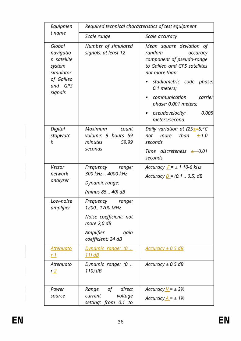
2.1.6. Tests of the eCall in respect of its GNSS receiver shall be performed with the test and auxiliary equipment specified in Table 1.
Table 1 – Recommended list of measurement instruments, test and auxiliary equipment
Equipment name
Required technical characteristics of test equipment
Scale range Scale accuracy
Global navigation satellite system simulator of Galileo and GPS signals
Number of simulated signals: at least 12
Mean square deviation of random accuracy component of pseudo-range to Galileo and GPS satellites not more than:
stadiometric code phase: 0.1 meters;
communication carrier phase: 0.001 meters;
pseudovelocity: 0.005 meters/second.
Digital stopwatch
Maximum count volume: 9 hours 59 minutes 59.99 seconds
Daily variation at (25±+5)°С not more than ± 1.0 seconds.
Time discreteness ± 0.01 seconds.
Vector network analyser
Frequency range: 300 kHz .. 4000 kHz
Dynamic range:
(minus 85 .. 40) dB
Accuracy F = ± 1·10-6 kHz
Accuracy D = (0.1 .. 0.5) dB
Low-noise amplifier
Frequency range: 1200.. 1700 MHz
Noise coefficient: not more 2,0 dB
Amplifier gain
EN 30 EN
Equipment name
Required technical characteristics of test equipment
Scale range Scale accuracy
coefficient: 24 dB
Attenuator 1
Dynamic range: (0 .. 11) dB
Accuracy ± 0.5 dB
Attenuator 2
Dynamic range: (0 .. 110) dB
Accuracy ± 0.5 dB
Power source
Range of direct current voltage setting: from 0.1 to 30 volts
Current intensity of output voltage: at least 3 amperes
Accuracy V = ± 3%
Accuracy A = ± 1%
N o t e – it is allowed to apply other similar types of equipment providing determination of characteristics with the required accuracy.
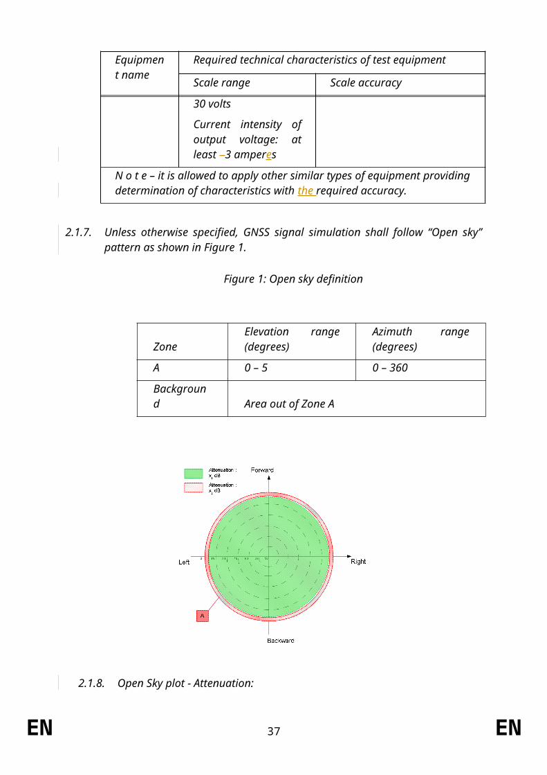
2.1.7. Unless otherwise specified, GNSS signal simulation shall follow “Open sky” pattern as shown in Figure 1.
Figure 1: Open sky definition
ZoneElevation range (degrees)
Azimuth range (degrees)
A 0 – 5 0 – 360
Background Area out of Zone A
EN 31 EN
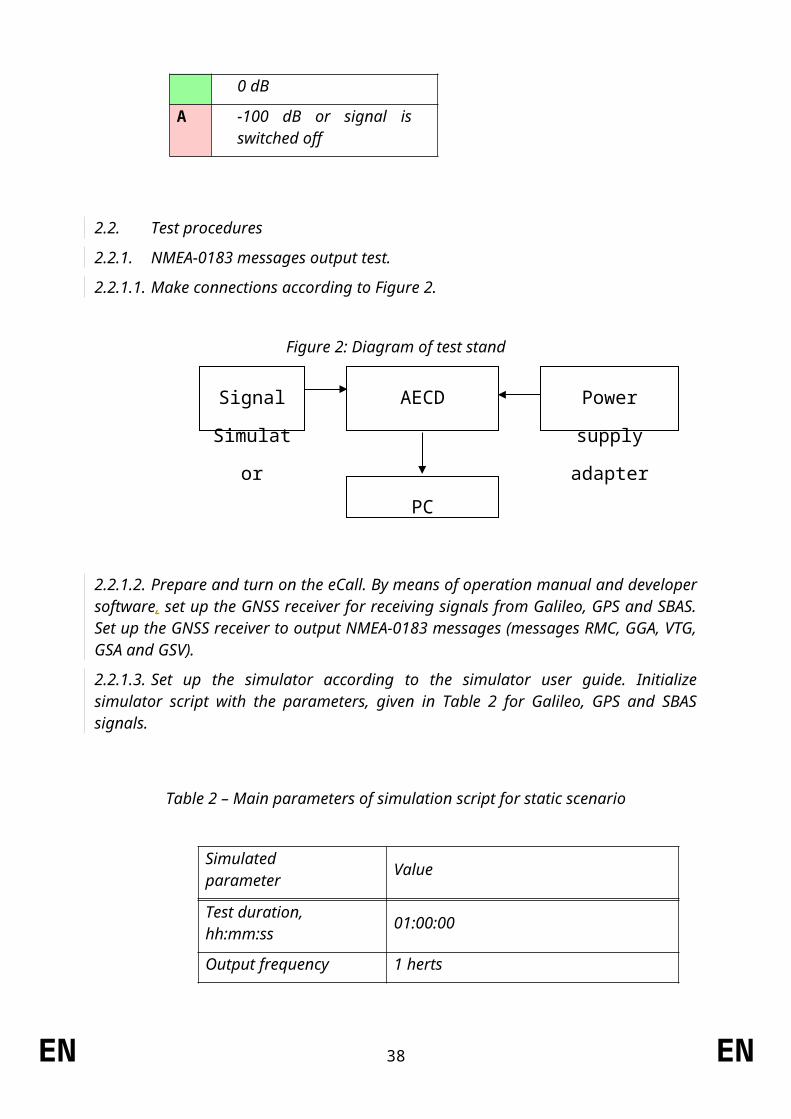
2.1.8. Open Sky plot - Attenuation:
0 dB
A -100 dB or signal is switched off
2.2. Test procedures
2.2.1.NMEA-0183 messages output test.
2.2.1.1. Make connections according to Figure 2.
Figure 2: Diagram of test stand
2.2.1.2. Prepare and turn on the eCall. By means of operation manual and developer software, set up the GNSS receiver for receiving signals from Galileo, GPS and SBAS. Set up the GNSS receiver to output NMEA-0183 messages (messages RMC, GGA, VTG, GSA and GSV).
2.2.1.3. Set up the simulator according to the simulator user guide. Initialize simulator script with the parameters, given in Table 2 for Galileo, GPS and SBAS signals.
EN 32 EN
Signal
Simulator
Power supply
adapter
PC
AECD
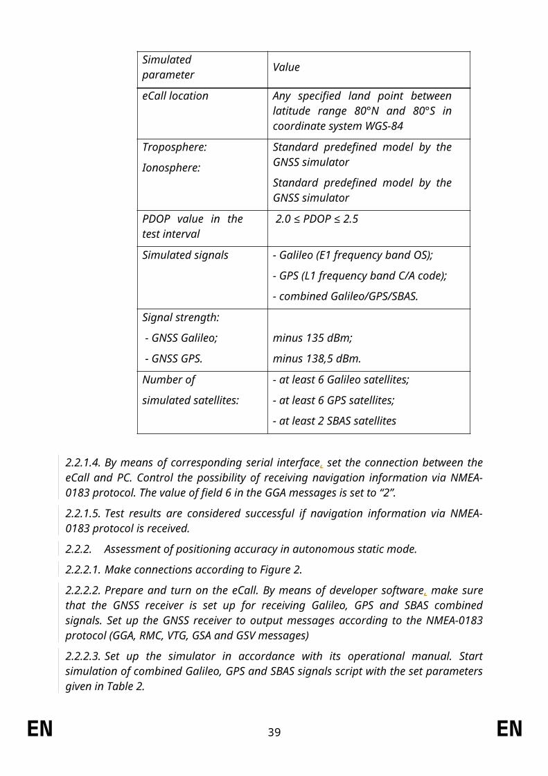
Table 2 – Main parameters of simulation script for static scenario
Simulated parameter Value
Test duration, hh:mm:ss 01:00:00
Output frequency 1 herts
eCall location Any specified land point between latitude range 80°N and 80°S in coordinate system WGS-84
Troposphere:
Ionosphere:
Standard predefined model by the GNSS simulator
Standard predefined model by the GNSS simulator
PDOP value in the test interval
2.0 ≤ PDOP ≤ 2.5
Simulated signals - Galileo (E1 frequency band OS);
- GPS (L1 frequency band C/A code);
- combined Galileo/GPS/SBAS.
Signal strength:
- GNSS Galileo;
- GNSS GPS.
minus 135 dBm;
minus 138,5 dBm.
Number of
simulated satellites:
- at least 6 Galileo satellites;
- at least 6 GPS satellites;
- at least 2 SBAS satellites
2.2.1.4. By means of corresponding serial interface, set the connection between the eCall and PC. Control the possibility of receiving navigation information via NMEA-0183 protocol. The value of field 6 in the GGA messages is set to “2”.
2.2.1.5. Test results are considered successful if navigation information via NMEA-0183 protocol is received.
2.2.2.Assessment of positioning accuracy in autonomous static mode.
2.2.2.1. Make connections according to Figure 2.
2.2.2.2. Prepare and turn on the eCall. By means of developer software, make sure that the GNSS receiver is set up for receiving Galileo, GPS and SBAS combined signals. Set up the GNSS receiver to output messages according to the NMEA-0183 protocol (GGA, RMC, VTG, GSA and GSV messages)
EN 33 EN
2.2.2.3. Set up the simulator in accordance with its operational manual. Start simulation of combined Galileo, GPS and SBAS signals script with the set parameters given in Table 2.
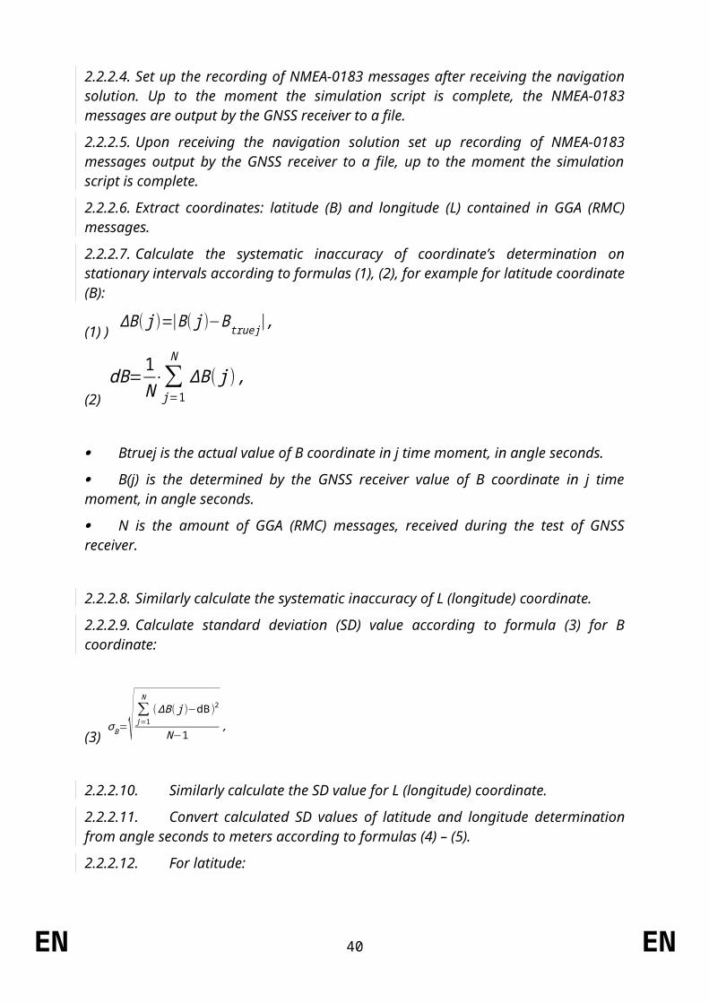
2.2.2.4. Set up the recording of NMEA-0183 messages after receiving the navigation solution. Up to the moment the simulation script is complete, the NMEA-0183 messages are output by the GNSS receiver to a file.
2.2.2.5. Upon receiving the navigation solution set up recording of NMEA-0183 messages output by the GNSS receiver to a file, up to the moment the simulation script is complete.
2.2.2.6. Extract coordinates: latitude (B) and longitude (L) contained in GGA (RMC) messages.
2.2.2.7. Calculate the systematic inaccuracy of coordinate’s determination on stationary intervals according to formulas (1), (2), for example for latitude coordinate (B):
(1) ) ΔB ( j )=|B( j )−Btruej|,
(2) dB= 1
N⋅∑
j=1
N
ΔB ( j) ,
Btruej is the actual value of B coordinate in j time moment, in angle seconds.
B(j) is the determined by the GNSS receiver value of B coordinate in j time moment, in angle seconds.
N is the amount of GGA (RMC) messages, received during the test of GNSS receiver.
2.2.2.8. Similarly calculate the systematic inaccuracy of L (longitude) coordinate.
2.2.2.9. Calculate standard deviation (SD) value according to formula (3) for B coordinate:
(3) σ B=√∑j=1
N
( ΔB( j )−dB )2
N−1,
2.2.2.10.Similarly calculate the SD value for L (longitude) coordinate.
2.2.2.11.Convert calculated SD values of latitude and longitude determination from angle seconds to meters according to formulas (4) – (5).
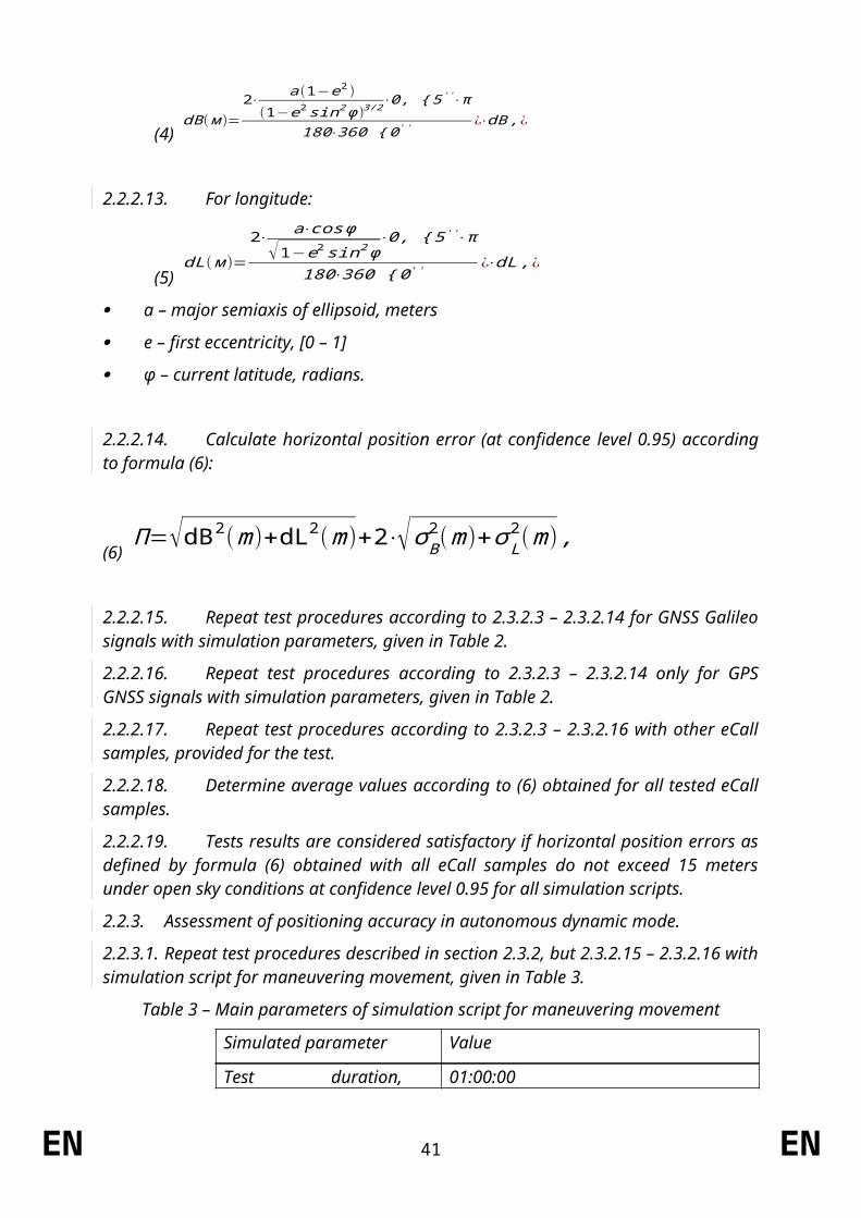
2.2.2.12.For latitude:
(4) dB ( м )=
2⋅ a(1−e2 )(1−e2 sin2 ϕ )3/2⋅0, { 5 ' '⋅π
180⋅360 { 0 ' ' ¿⋅dB ,¿
2.2.2.13.For longitude:
EN 34 EN
(5) dL( м )=
2⋅ a⋅cos ϕ√1−e2 sin2 ϕ
⋅0, { 5' '⋅π
180⋅360 { 0 ' ' ¿⋅dL ,¿
а – major semiaxis of ellipsoid, meters
e – first eccentricity, [0 – 1]
φ – current latitude, radians.
2.2.2.14.Calculate horizontal position error (at confidence level 0.95) according to formula (6):
(6) П=√dB2 (m)+dL2(m)+2⋅√σ B
2 (m)+σ L2 ( m),
2.2.2.15.Repeat test procedures according to 2.3.2.3 – 2.3.2.14 for GNSS Galileo signals with simulation parameters, given in Table 2.
2.2.2.16.Repeat test procedures according to 2.3.2.3 – 2.3.2.14 only for GPS GNSS signals with simulation parameters, given in Table 2.
2.2.2.17.Repeat test procedures according to 2.3.2.3 – 2.3.2.16 with other eCall samples, provided for the test.
2.2.2.18.Determine average values according to (6) obtained for all tested eCall samples.
2.2.2.19.Tests results are considered satisfactory if horizontal position errors as defined by formula (6) obtained with all eCall samples do not exceed 15 meters under open sky conditions at confidence level 0.95 for all simulation scripts.
2.2.3.Assessment of positioning accuracy in autonomous dynamic mode.
2.2.3.1. Repeat test procedures described in section 2.3.2, but 2.3.2.15 – 2.3.2.16 with simulation script for maneuvering movement, given in Table 3.
Table 3 – Main parameters of simulation script for maneuvering movement
Simulated parameter Value
Test duration, hh:mm:ss 01:00:00
Output frequency 1 hertz
eCall location Any specified land point between latitude range 80°N and 80°S in coordinate system WGS-84
Model of movement:
- speed, km/h;
- turn radius, meters;
- turn acceleration, meters/second2.
Maneuvering movement
140
500
0.2
EN 35 EN
Troposphere:
Ionosphere:
Standard predefined model by the GNSS simulator
Standard predefined model by the GNSS simulator
PDOP value in the test time interval
2.0 ≤ PDOP ≤ 2.5
Simulated signals Combined Galileo/GPS/SBAS
Signal strength:
- GNSS Galileo;
- GNSS GPS.
minus 135 dBm;
minus 138.5 dBm.
Number of
simulated satellites:
- at least 6 Galileo satellites;
- at least 6 GPS satellites;
- at least 2 SBAS satellites
2.2.3.2. Determine average values according to (6) obtained for all tested eCall samples.
2.2.3.3. Tests results are considered satisfactory if horizontal position errors obtained with all eCall samples do not exceed 15 meters under open sky conditions at confidence level 0.95.
2.2.4.Movement in shadow areas, areas of intermittent reception of navigation signals and urban canyons.
2.2.4.1. Repeat test procedures described in section 2.3.3 for simulation script for movement in shadow areas and areas of intermittent reception of navigation signals (given in Table 4) with an urban canyon signal pattern described in Figure 3.
Table 4 – Main parameters of movement in shadow areas and areas of intermittent reception of navigation signals
Simulated parameter Value
Test duration, hh:mm:ss 01:00:00
Output frequency 1 hertz
eCall location Any specified land point between latitude range 80°N and 80°S in coordinate system WGS-84
Model of movement:
- speed, km/h;
- turn radius, meters;
- turn acceleration, meters/second2.
Maneuvering movement
140
500
0.2
Satellite visibility:
- signal visibility 300
EN 36 EN
Simulated parameter Value
intervals, seconds;
- signal absence intervals, seconds.
600
Troposphere:
Ionosphere:
Standard predefined model by the GNSS simulator
Standard predefined model by the GNSS simulator
PDOP value in the test time interval
3.5 ≤ PDOP ≤ 4.0
Simulated signals Combined Galileo/GPS/SBAS
Signal strength:
- GNSS Galileo;
- GNSS GPS.
minus 135 dBm;
minus 138.5 dBm.
Number of
simulated satellites:
- at least 6 Galileo satellites;
- at least 6 GPS satellites;
- at least 2 SBAS satellites
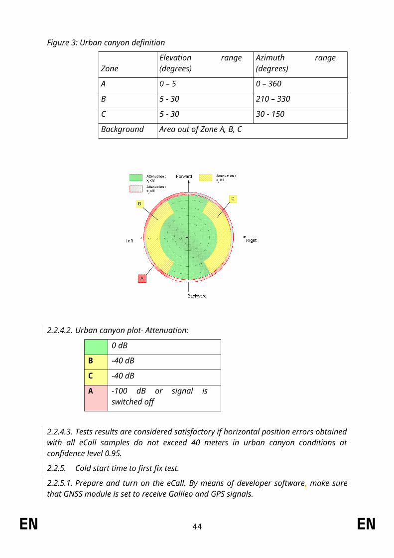
Figure 3: Urban canyon definition
ZoneElevation range (degrees) Azimuth range (degrees)
A 0 – 5 0 – 360
B 5 - 30 210 – 330
C 5 - 30 30 - 150
Background Area out of Zone A, B, C
EN 37 EN
2.2.4.2. Urban canyon plot- Attenuation:
0 dB
B -40 dB
C -40 dB
A -100 dB or signal is switched off
2.2.4.3. Tests results are considered satisfactory if horizontal position errors obtained with all eCall samples do not exceed 40 meters in urban canyon conditions at confidence level 0.95.
2.2.5.Cold start time to first fix test.
2.2.5.1. Prepare and turn on the eCall. By means of developer software, make sure that GNSS module is set to receive Galileo and GPS signals.
2.2.5.2. Delete all position, velocity, time, almanac and ephemeris data from the GNSS receiver.
2.2.5.3. Set up the simulator according to the simulator user guide. Initialize simulator script with the parameters, given in Table 2 for Galileo and GPS signals with signal level minus 130 dBm.
[2.2.5.4.] By means of a stop watch, measure time interval between signal simulation start and the first navigation solution result.
2.2.5.4.[2.2.5.5.] Conduct test procedures according to 2.3.5.2 – 2.3.5.4 at least 10 times.
2.2.5.5.[2.2.5.6.] Calculate average time to first fix in cold start mode based on measurements for all eCall samples, provided for the test.
EN 38 EN
2.2.5.6.[2.2.5.7.] The test result is considered to be positive, if average values of time to first fix calculated as described in 2.3.5.6, do not exceed 60 seconds for signal level down to minus 130 dBm for all the simulated signals.
2.2.5.7.[2.2.5.8.] Repeat test procedure according to 2.3.5.1 – 2.3.5.5 with signal level minus 140 dBm.
2.2.5.8.[2.2.5.9.] The test result according to 2.3.5.8 is considered to be positive, if average values of time to first fix, calculated as described in 2.3.5.6 do not exceed 300 seconds for signal level down to minus 140 dBm for all the simulated signals.
2.2.6.Test of re-acquisition time of tracking signals after block out of 60 seconds.
2.2.6.1. Prepare and turn on the eCall according to operational manual. By means of the developer software, make sure that GNSS receiver is set up to receive Galileo and GPS signals.
2.2.6.2. Set up the simulator according to the simulator user guide. Initialize simulator script with the parameters, given in Table 2 for Galileo and GPS signals with signal level minus 130 dBm.
2.2.6.3. Wait for 15 minutes and make sure the GNSS receiver has calculated eCall position.
2.2.6.4. Disconnect the GNSS antenna cable from the eCall and connect it again after time interval of 60 seconds. By means of stopwatch, determine time interval between cable connection moment and restoration of satellites tracking and calculation of the navigation solution.
2.2.6.5. Repeat test procedure according to 2.3.6.4 at least 10 times.
2.2.6.6. Calculate average value of re-acquisition time of satellite tracking signals by the eCall for all performed measurements and all eCall samples provided for the test.
2.2.6.7. The test result is considered to be positive, if average values of re-acquisition time after block out of 60 seconds measured as described in 2.3.6.6, do not exceed 20 seconds.
2.2.7.Test of GNSS receiver sensitivity in cold start mode, tracking mode, and re-acquisition scenario.
2.2.7.1. Turn on the vector network analyser. Calibrate the network vector analyser according to its operational manual.
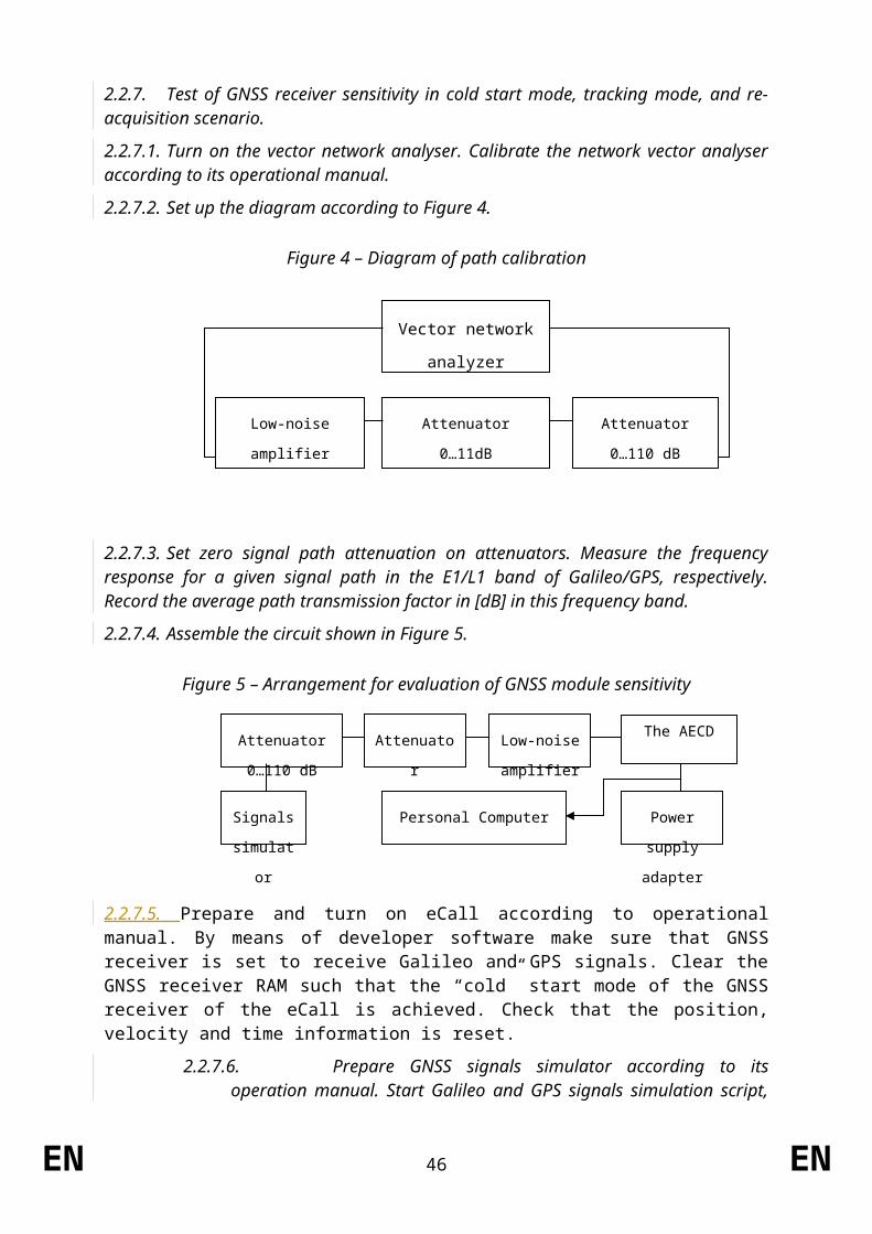
2.2.7.2. Set up the diagram according to Figure 4.
Figure 4 – Diagram of path calibration
EN 39 EN
Attenuator
0…11dB
Low-noise amplifier Attenuator
0…110 dB
Vector network
analyzer
2.2.7.3. Set zero signal path attenuation on attenuators. Measure the frequency response for a given signal path in the E1/L1 band of Galileo/GPS, respectively. Record the average path transmission factor in [dB] in this frequency band.
2.2.7.4. Assemble the circuit shown in Figure 5.
Figure 5 – Arrangement for evaluation of GNSS module sensitivity
2.2.7.5. Prepare and turn on eCall according to operational manual. By means of developer software make sure that GNSS receiver is set to receive Galileo and GPS signals. Clear the GNSS receiver RAM such that the “cold” start mode of the GNSS receiver of the eCall is achieved. Check that the position, velocity and time information is reset.
2.2.7.6. Prepare GNSS signals simulator according to its operation manual. Start Galileo and GPS signals simulation script, with parameters given in Table 2. Set output power level of the simulator to minus 144 dBm.
2.2.7.7. By means of a stopwatch, measure time interval between signal simulation start and the first navigation solution result.
2.2.7.8. Set the signal path attenuation on attenuators such that the signal on eCall antenna input is equal to minus 155 dBm
2.2.7.9. By means of a stopwatch, verify that the eCall still provides navigation solution for at least 600 seconds.
2.2.7.10.Set the signal path attenuation on attenuators such that the signal on eCall antenna input is equal to minus 150 dBm.
2.2.7.11.Disconnect the GNSS antenna cable from the eCall and connect it again after time interval of 20 sec.
2.2.7.12.By means of stopwatch, determine time interval between cable connection moment and restoration of satellites tracking and calculation of the navigation solution.
2.2.7.13.The test result is considered to be positive in case:
the value of time to first fix in “cold” start mode, as measured in 2.3.7.7, do not exceed 3600 seconds at signal level on the antenna input of the eCall of minus 144 dBm;
the GNSS navigation solution is available for at least 600 seconds at signal level on the antenna input of the eCall of minus 155 dBm as measured in 2.3.7.9;
and re-acquisition of GNSS signals and calculation of the navigation solution at signal level on the antenna input of the eCall of minus 150 dBm is possible and time interval measured in 2.3.7.12 does not exceed 60 seconds.
EN 40 EN
Power supply
adapter
Personal Computer
The AECDLow-noise
amplifier
Attenuator
0…11dB
Attenuator
0…110 dB
Signals
simulator
EN 41 EN

ANNEX VII
In-vehicle system self-test
1. Requirements
[1.1.] The following requirements apply to a vehicle with eCall in-vehicle system installed, components and separate technical units.
1.1.[1.2.] Performance requirements
1.1.1.[1.2.1.] The eCall system shall carry out a self-test at each system power-up.
[1.2.2.] Where technically feasible, tThe self-test function shall monitor at least the technical items listed in Table 1.
1.1.2.[1.2.3.] A warning in form of either a visual tell-tale or a warning message in a common space shall be provided in case a failure is detected by the self-test function.
1.1.2.1.[1.2.3.1.] It shall remain activated while the failure is present.
1.1.2.2.[1.2.3.2.] It may be cancelled temporarily, but shall be repeated whenever the ignition or vehicle master control switch is being activated.
1.2.[1.3.] Provisions for the periodic technical inspection
[1.3.1.] It shall be possible to verify the integrity of the eCall in-vehicle system via the serial electronic vehicle interface of the standard on-board diagnostic connector (OBD). According to this it shall at least be possible to test the accuracy of the Minimum Set of Data, the availability of Public Land Mobile Network(s) and the functionality of the voice communication by audible means (e. g. short echo test).
1.2.1.[1.3.2.] All necessary information for the proper conduct of the test shall be made freely available.
1.3.[1.4.] Documentation requirements
[1.4.1.] The manufacturer shall provide the type-approval authorities with documentation in accordance with Table 1, which shall contain for each item the following information technical principle applied to monitor the item.
(a) Which of the items listed are being monitored by the self-test function.
(b) For each item that is being monitored: The technical principle applied to monitor the item.
(c) For each item that is not being monitored: The technical reason why it is not feasible to monitor the item in the chosen system design.
EN 42 EN
STOYANOVA Elitza (ENTR), 03/12/15,
A definition may be added in Art. 3 for common space: ""Common space" means an area on which two or more information functions (e.g. symbol) may be displayed but not simultaneously
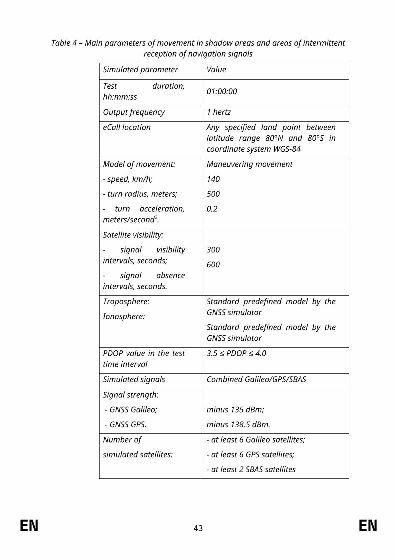
Table 1: Template of information for self-test function
Item If yes: Technical principle applied for monitoring
eCall ECU is in working order (e.g. no internal hardware failure, processor/memory is ready, logic function in expected default state)
External mobile network antenna is connected
Mobile network communication device is in working order (no internal hardware failure, responsive)
External GNSS antenna is connected
GNSS receiver is in working order (no internal hardware failure, output within expected range)
Crash control unit is in working order (e.g. no internal hardware failure, processor is ready, logic function in expected default state)
No communication failures (bus connection failures) of relevant components
SIM is present (this item only applies if a removable SIM is used)
Software image integrity
Dedicated battery Power source is connected
State of health of dedicated battery
Microphone(s) are connected
Loudspeaker(s) are connected
Manual call button is connected
Status indicator is connected
EN 43 EN
2. Test procedure
2.1. Self-test function verification test
[2.1.1.] The following test shall be performed on a vehicle with an eCall in-vehicle system installed or on a representative arrangement of components for the approval of vehicles, components or separate technical units.
2.1.1.[2.1.2.] Simulate a malfunction of the eCall system by introducing a critical failure in one or more of the items monitored by the self-test function according to the technical documentation provided by the manufacturer. The item(s) shall be selected at the discretion of the type-approval authority.
2.1.2.[2.1.3.] Power the eCall system up (e.g. by switching the ignition ‘on’ or activating the vehicle’s master control switch, as applicable) and verify that the malfunction indicator illuminates shortly afterwards.
2.1.3.[2.1.4.] Power the eCall system down (e.g. by switching the ignition ‘off’ or deactivating the vehicle’s master control switch, as applicable) and restore it to normal operation.
2.1.4.[2.1.5.] Power the eCall system up and verify that the malfunction indicator does not illuminate or extinguishes shortly after illuminating initially.
EN 44 EN
ANNEX VIII
Technical requirements and test procedures related to privacy and data protection
EN 45 EN
Part I
Procedure for verifying the lack of traceability of eCall in-vehicle systems
1. Purpose1.1. This test procedure shall apply to the requirement set out in Article 6(4) of
Regulation (EU) 2015/758.
1.2. This is to ensure that the 112-based eCall in-vehicle system is not traceable and is not subject to any constant tracking in its normal operational status.
2. Requirements2.1. The 112-based eCall in-vehicle system is not available for communication with the
PSAP if the PSAP test point initiates the communication.2.2. Failure to establish the connection can be attributed to the 112-based eCall in-
vehicle system not being registered on the network.
3. Test procedure[3.1.] The following tests shall be performed on a representative arrangement of parts
(without a vehicle body) for the approval of vehicles, components or separate technical units.
3.1.[3.2.] This test shall be performed after successful connection of the eCall IVS with the network and registration of the device so as to facilitate transmission of the MSD.
3.1.1.[3.2.1.] The initial emergency call must have been ‘cleared down’ and deregistered from the network prior to this test (e.g. hang up), otherwise the PSAP test point will be enabled to connect.
3.1.2.[3.2.2.] Before performing the test, ensure that:(a) one of the connection procedures defined in Paragraph 2.7 of Annex I to this
Regulation, as agreed between the technical service and the manufacturer, will be applied for any test call;
(b) the dedicated PSAP test point is available to receive an eCall emitted by the 112-based system;
(c) that the vehicle ignition or master control switch is activated;(d) that any TPS or added-value service system is disabled.
3.1.3.[3.2.3.] Leave the 112-based eCall IVS powered.3.1.4.[3.2.4.] Via the PSAP test point, attempt to connect to the 112-based eCall IVS.
4. Assessment
4.1. The requirement is determined to have been passed if the 112-based eCall in-vehicle system is not available for communication with the PSAP when the PSAP test point attempts to connect.
4.2. The establishment of connection with the 112-based eCall IVS when the PSAP test point initiates the communication constitutes a failure.
EN 46 EN
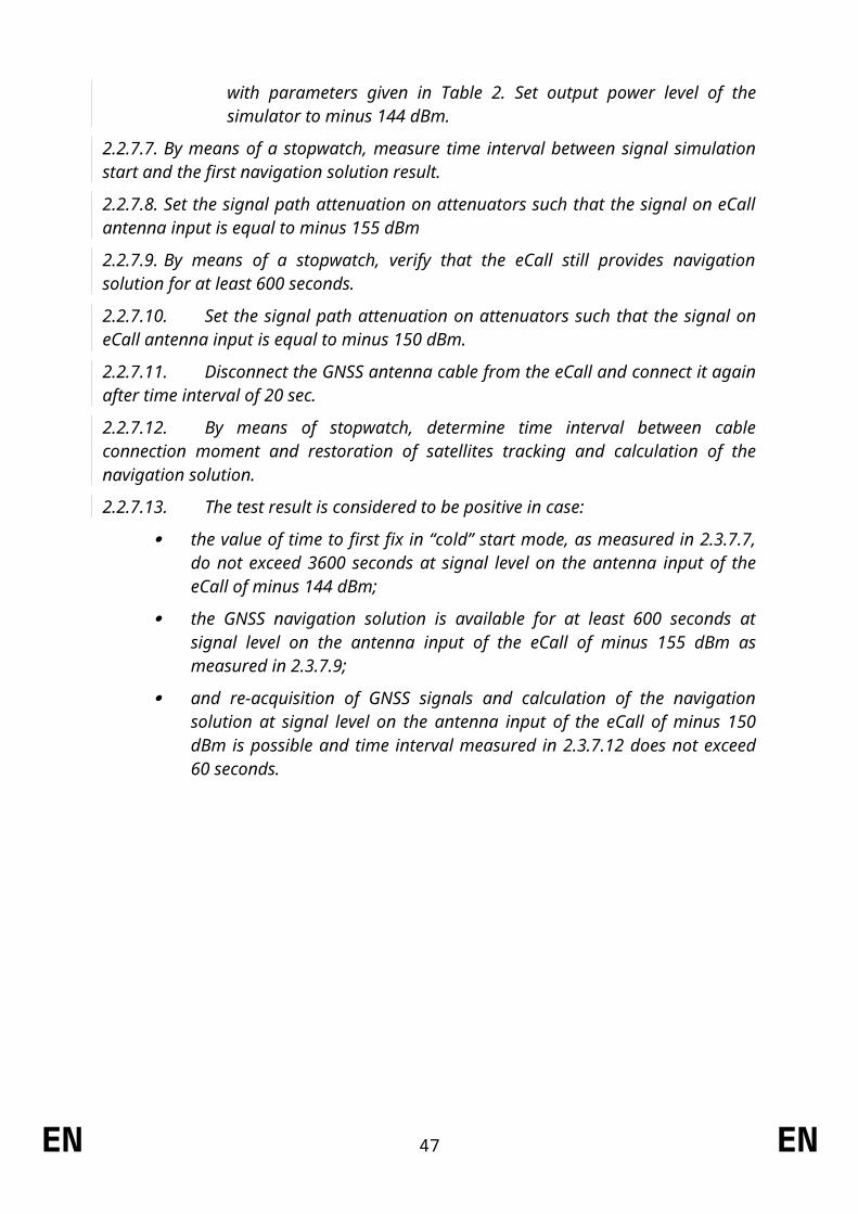
Part II
Procedure for verifying the length of time an eCall log file is stored by the eCall in-vehicle system
1. Purpose1.1. This test procedure shall apply to the requirement set out in Article 6(3) of
Regulation (EU) 2015/758.
1.2. This is to demonstrate that the personal data shall not be retained by the eCall in-vehicle system longer than necessary for the purpose of handling the emergency situation. Those data shall be fully deleted as soon as they are no longer necessary for that purpose. This is to be judged by proving that eCall log files are not kept beyond 13 hours from the point of initiating an eCall.
2. Requirements2.1. When interrogated, the eCall in-vehicle system shall not maintain any record of an
eCall in its memory beyond 13 hours from the point of initiating an eCall.
3. Test conditions3.1. The Technical Service shall be facilitated to have access to the part of the system
where the eCall log files are stored in the IVS[3.2.] The following test shall be performed on a representative arrangement of parts for the
approval of vehicles, components or separate technical units.
4. Test Method4.1. The tests as described in paragraph 2.7 of Annex I shall be carried out. They require
that a test call is placed in order for functionality checks to be made.4.2. 13 hours after a test call has been placed, the Technical Service tester shall be
facilitated with access to where the eCall log files are stored in the IVS. This will involve the potential to download from the IVS any log files so that they can be viewed by the tester.
5. Assessment5.1. The requirement is determined to have been passed if no log files are present in the
eCall in-vehicle system memory.5.2. The presence of a log file pertaining to an eCall that has occurred more than 13
hours ago constitutes a failure.
EN 47 EN
Part III
Procedure for verifying the automatic and continuous removal of data in the internal memory of eCall in-vehicle systems
1. Purpose1.1. This test procedure shall apply to the requirement set out in Article 6(5) of
Regulation (EU) 2015/758.
[1.2.] This is to demonstrate that in the internal memory of the 112 based eCall in-vehicle system, maximum ofonly the last three locations of the vehicle shall be retained.
2. Requirements2.1. When interrogated, the eCall in-vehicle system shall not maintain more than three
recent locations of the vehicle.
3. Test conditions3.1. The Technical Service shall be facilitated to have access to the part of the system
where the vehicle location data are stored in the IVS internal memory.[3.2.] The following test shall be performed on a representative arrangement of parts for the
approval of components or separate technical units.
4. Test Method4.1. The Technical Service tester shall be facilitated with access to where the vehicle
location data are stored in the IVS internal memory. This will involve the potential to download from the IVS any stored locations so that they can be viewed by the tester.
5. Assessment[5.1.] The requirement is determined to have been passed if maximum of last no more than
three locations are present in the eCall in-vehicle system memory.5.1.[5.2.] The presence of more than three locations constitutes a failure.
EN 48 EN

Part IV
Procedure for verifying the non- exchange of personal data between eCall in-vehicle systems and third party services systems
Option 1:
1. Purpose1.1. This test procedure shall apply to the requirement set out in Article 6(11) of
Regulation (EU) 2015/758.
1.2. This is to ensure that the 112-based eCall in-vehicle system and any additional system providing TPS eCall or an added-value service are designed in such a way that no exchange of personal data between them is possible.
2. Requirements[2.1.] The following requirements apply to eCall in-vehicle systems, components and
separate technical units that shall be used in conjunction with a TPS eCall in-vehicle system.
2.1.[2.2.] Performance requirements2.1.1.[2.2.1.] There is no exchange of personal data between the 112-based eCall in-vehicle
system and any additional system providing TPS eCall or an added-value service.2.1.2.[2.2.2.] Following an eCall made via the 112-based eCall in-vehicle system, no log of
this eCall shall be recorded in the memory of the TPS eCall or added-value service system.
3. Test procedure[3.1.] The following tests shall be performed either on a vehicle with an eCall in-vehicle
system installed or on a representative arrangement of parts, for the approval of vehicles, components or separate technical units.
3.1.[3.2.] The TPS system shall be disabled for the duration of the test call. 3.1.1.[3.2.1.] Before performing the test call, ensure:
(a) that one of the connection procedures defined in Paragraph 2.7 of Annex I to this Regulation, as agreed between the technical service and the manufacturer, will be applied for any test call;
(b) that the dedicated PSAP test point is available to receive an eCall emitted by the 112-based system;
(c) that a false eCall to a genuine PSAP cannot be made over the live network; and
(d) that the vehicle ignition or master control switch is activated.
3.1.2.[3.2.2.] Perform a test call by applying a manual trigger of the system (push mode) with the TPS disabled.
[3.2.3.] Verify :
that a call was established with the PSAP test point by a record of the PSAP test point showing that it received a call initiation signal or by a successful voice connection to the PSAP test point; and
EN 49 EN
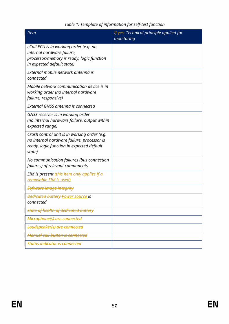
3.1.3.[3.2.4.] Clear down the test call using the appropriate PSAP test point command (e.g. hang up).
3.1.4.[3.2.5.] If the call attempt of the 112-based system fails during the test, the test procedure may be repeated.
3.2.[3.3.] The lack of a log file in the TPS system shall be verified via access to the part of the system where eCall log files are stored.
3.2.1.[3.3.1.] The Technical Service tester shall be facilitated with access to where the eCall log files are stored in the IVS. This will involve the potential to download from the IVS any log files so that they can be viewed by the tester.
3.2.2.[3.3.2.] The requirement is determined to have been passed if no log files are present in the TPS system in-vehicle system memory.
3.2.3.[3.3.3.] The presence of a log file in the TPS system pertaining to an eCall that has occurred via the 112-based system constitutes a failure.
3.3.[3.4.] Connection proceduresThe connection procedures defined in paragraph 2.7 of Annex I to this Regulation shall apply.
Option 2:
[1.] Purpose[1.1.] This test procedure shall apply to the requirement set out in Article 6(11) of Regulation
(EU) 2015/758.
[1.2.] This is to ensure that the 112-based eCall in-vehicle system and any additional system providing TPS eCall or an added-value service are designed in such a way that no exchange of personal data between them is possible.
[2.] Requirements[2.1.] The following requirements apply to vehicles with 112-based and TPS or added-value
eCall in-vehicle systems installed.[2.2.] Documentation requirements[2.2.1.] The manufacturer shall provide a statement which affirms that the 112-based eCall
in-vehicle system and any additional system providing TPS eCall or an added value service are designed in such a way that no exchange of personal data between them is possible.
[2.2.2.] The manufacturer shall provide the type-approval authority with an explanation and technical documentation which shows, in overall terms, how this is achieved. For example:
[2.2.2.1.] Documentation that shows, to the satisfaction of the type-approval authority, that there is no direct wiring or memory shared between the 112-based eCall in-vehicle system and any additional system providing TPS eCall or an added value service system.
[2.2.2.2.] Documentation that shows, to the satisfaction of the type-approval authority, that there is no data pathway existing in the vehicle, without an adequate firewall or separation by encryption, that allows an exchange of information between the 112-based eCall in-vehicle system and any additional system providing TPS eCall or an added value service system.
EN 50 EN
ANNEX IX
List of types classes of vehicles exempted from the scope under Article 2(3) of this Regulation
[1. Armoured vehicles of categories M1 and N1, as defined in point 5.2 of Part A of Annex II to Directive 2007/46/EC, equipped with armoured security glazing class BR 7 according to the classification under European standard EN 1063:2000 (Test and Classification for Ballistic Security Glazing) and with body parts complying with European standard EN 1522:1999 (Bullet Resistance in Windows, Doors, Shutters and Blinds), where those vehicles, due to their special purpose, cannot meet the requirements of Regulation (EU) No 2015/758 and of this Regulation.]
EN 51 EN