· Web viewDomestic Water Packaged Booster Pumps Part 1 General 1.1 SECTION INCLUDES Variable...
24
Domestic Water Packaged Booster Pumps 22 11 23.13 Division 22 - Plumbing 22 11 00 - Facility Water Distribution 22 11 13 - Facility Water Distribution Piping 22 11 16 - Domestic Water Piping 22 11 19 - Domestic Water Piping Specialties 22 11 23 - Domestic Water Pumps 22 11 23.13 Domestic Water Packaged Booster Pumps PART 1 GENERAL 1.1 SECTION INCLUDES Variable Speed Pumping Package Pump Control Panel Variable Frequency Drive Sensor Transmitters Sequence of Operation 1.2 REFERENCES AWWA - American Water Works Association ANSI - American National Standards Institute ASTM - American Standards for Testing Materials HI - Hydraulic Institute ASME - American Society of Mechanical Engineers UL - Underwriters Laboratories ISO - International Standards Organization NEMA - National Electrical Manufacturers Association ETL - Electrical Testing Laboratories CSA - Canadian Standards Association NEC - National Electrical Code SPECIFICATIONS AQUAFXLSPEC R2 . . . . . . . . . . . . . . . . . . . . . . . . . . . . . . . . . . . . . . . .
-
Upload
phungkhanh -
Category
Documents
-
view
219 -
download
1
Transcript of · Web viewDomestic Water Packaged Booster Pumps Part 1 General 1.1 SECTION INCLUDES Variable...

Domestic Water Packaged Booster Pumps 22 11 23.13
Division 22 - Plumbing22 11 00 - Facility Water Distribution22 11 13 - Facility Water Distribution Piping 22 11 16 - Domestic Water Piping 22 11 19 - Domestic Water Piping Specialties 22 11 23 - Domestic Water Pumps
22 11 23.13 Domestic Water Packaged Booster Pumps
PART 1 GENERAL1.1 SECTION INCLUDES
Variable Speed Pumping PackagePump Control PanelVariable Frequency Drive Sensor TransmittersSequence of Operation
1.2 REFERENCESAWWA - American Water Works Association ANSI - American National Standards Institute ASTM - American Standards for Testing Materials HI - Hydraulic Institute ASME - American Society of Mechanical Engineers UL - Underwriters Laboratories ISO - International Standards Organization NEMA - National Electrical Manufacturers AssociationETL - Electrical Testing LaboratoriesCSA - Canadian Standards AssociationNEC - National Electrical CodeIEC - International Electrotechnical CommissionNSF – NSF InternationalISO – International Organization for StandardizationASHRAE – American Society of Heating, Refrigerating and Air-Conditioning Engineers
SPECIFICATIONSAQUAFXLSPEC R2
. . . . . . . . . . . . . . . . . . . . . . . . . . . . . . . . . . . . . . . . . . . . . . . . . . . . . . . . . . . . . . . . . . . . . . . . . . . . . . . . . . . . . .
. . . . . . . . . . . . . . . .

AQUAFORCE XL SPECIFICATIONS 2. . . . . . . . . . . . . . . . . . . . . . . . . . . . . . . . . . . . . . . . . . . . . . . . . . . . . . . . . . . . . . . . . . . . . . . . . . . . . . . . . . . . . . . . . . . . . . . . 1.3 SUBMITTALS
SUBMITTALS SHALL INCLUDE THE FOLLOWING:1. System summary sheet2. Sequence of operation3. Shop drawing indicating dimensions, required clearances and location and size of each field
connection and anchoring detail4. Power and control wiring diagrams5. System profile analysis including variable speed pump curves and system curve. The
analysis shall also include pump & motor efficiencies, staging points, job specific load profile, horsepower and kilowatt/hour consumption.
6. Pump data sheetsSubmittals must be specific to this project. Generic submittals will not be accepted.Each supplier shall list any exceptions to the specification. If no departures from the specification are identified, the supplier shall be bound by the specification.
1.4 QUALITY ASSURANCEThe pumping package shall be assembled by the pump manufacturer. An assembler of pumping systems not actively engaged in the design and construction of centrifugal pumps shall not be considered a pump manufacturer. The manufacturer shall assume "Unit Responsibility" for the complete pumping package. Unit responsibility shall be defined as responsibility for interface and successful operation of all system components supplied by the pumping system manufacturer.The manufacturer shall have a minimum of 30 years experience in the design and construction of packaged pumping systems, and over 50 years in active design/ production of centrifugal pumps.The pumping system shall be factory tested to the job specific condition points prior to shipment. A check test procedure shall be conducted with motors connected to VFD output / motor starters and it shall test all inputs, outputs and program execution specific to this application, including presetting of all job specific program parameters.Bidders shall comply with all sections of this specification relating to packaged pumping systems. Any deviations from this specification shall be bid as a voluntary alternate clearly defined in writing. If no exceptions are noted, the supplier or contractor shall be bound by these specifications.A copy of manufacturer's certificate of insurance shall be made available upon request showing as a minimum, general liability coverage of $1,000,000, and an excess liability coverage of $10,000,000. The pumping package shall be certified by an approved independent testing and certification organization as being compliant with the requirements of NSF/ANSI 61 for potable drinking water and NSF-61 Annex G for low lead content.Manufacturer shall be listed by UL as a manufacturer of packaged pumping systems under UL/cUL category QCZJ.Manufacturer shall be listed by UL as a manufacturer of control panels under UL 508A.The manufacturer’s production facility shall be certified by an approved independent testing and certification organization as being compliant with the requirements of NSF/ANSI 61 and NSF-61 Annex G. The manufacturing facility shall be subjected to periodic inspections and audits.
PART 2 PRODUCTS2.1 ACCEPTABLE MANUFACTURERS
Subject to compliance with these specifications, the following manufacturers shall be acceptable:
1. Goulds Water Technology2. Pre-approved equal
2.2 MANUFACTURED UNITS

AQUAFORCE XL SPECIFICATIONS 3. . . . . . . . . . . . . . . . . . . . . . . . . . . . . . . . . . . . . . . . . . . . . . . . . . . . . . . . . . . . . . . . . . . . . . . . . . . . . . . . . . . . . . . . . . . . . . . . Furnish and install as shown on the plans a Variable Speed Booster System model number
_____________ as manufactured by Goulds Water Technology or approved equal. System shall be capable of delivering _____ Gallons per Minute (GPM) at _____ PSI with a _____ PSI minimum suction pressure for a boost or flooded application , or _____ Feet of Lift for a lift application. Suction and discharge headers shall be ____" and constructed of 304 series stainless steel.Manufacturer shall be listed by Underwriters Laboratories as a manufacturer of packaged pumping systems.The entire pumping package shall be NSF/ANSI/NSF-61 certified for potable drinking water and NSF-61 Annex G for a wetted area, weighted average lead content ≤0.25%.The system shall meet or exceed the intent of ASHRAE 90.1-2010 with a sensor located near the critical fixture or fixtures that determine the required pressure.The control system shall include, as a minimum, the programmable logic station controller, variable frequency drives, a manifold mounted 4-20mA pressure transducer and any additional equipment as specified or as required to properly execute the sequence of operation. System shall require only suction, discharge and drain connections and single point power connection from a service entrance disconnect.All components shall be mounted and shipped as a single unit.Pumps shall be manufactured by Xylem.The discharge of each pump shall be fitted with a check valve appropriate for station operation. Each pump and discharge valve assembly shall also be equipped with isolation valves so that the pump can be serviced while system is still filled.Pressure gauges shall be installed on the suction and discharge headers.Piping shall be sized so that water velocity shall not exceed 10 fps (feet per second) in either the valves or manifolds.Pumps shall be protected from thermal accumulation via individual thermal purge assembly relief mechanisms (optional).The system shall not be comprised of proprietary components (eg motors, drives etc) that limit the user to a single source for replacement components.
2.3 COMPONENTS2.3.a. PUMP LOGIC CONTROLLER
1. The pump logic controller shall be a AquaForce XLS pump controller. Enclosure shall be a standard NEMA 1 or an optional NEMA 4 with a NEMA 4 operator interface. The pump logic controller shall be listed by and bear the label of Underwriter's Laboratory, Inc. (UL/cUL). The controller program shall be specifically designed by the pump manufacturer for packaged pressure booster applications.
2. The control panel with controls shall be built in accordance with NEC, and shall comply with UL standards. Pump station manufacturer shall be authorized under UL508A to manufacture its own control panels. All equipment and wiring shall be mounted within the enclosure and each device shall be labeled with proper identification. All adjustments and maintenance shall be accessible from the front of the control enclosure. A complete wiring circuit diagram and legend with terminals, components, and wiring completely identified shall be provided. Main disconnect shall be interlocked with door and shall have a through door operator and be sized as shown in the technical data sheet. The control enclosure shall be constructed of 14-gauge steel and the back plate assembly shall be constructed of 14-gauge steel.
3. One or more industrial grade programmable logic controllers shall handle all control logic. The PLC(s) shall provide demand controlled sequential pump start-up, shutdown and safety features through pressure sensing, flow sensing and voltage sensing devices. An LED visual status light is provided for each I/O point to indicate on/off status. Industrial grade programmable logic controllers shall handle all logic for system control, timing, and control of VFD speed. All PLCs shall have a built in clock calendar and shall communicate via the internal - 100 megabit Ethernet network. PLC shall possess a minimum of 2 megabytes of total memory.
4. The pump logic controller shall be microcomputer based and hold its software in a non-volatile flash memory. On-line field modified data entries, such as set point, alternation,

AQUAFORCE XL SPECIFICATIONS 4. . . . . . . . . . . . . . . . . . . . . . . . . . . . . . . . . . . . . . . . . . . . . . . . . . . . . . . . . . . . . . . . . . . . . . . . . . . . . . . . . . . . . . . . . . . . . . . . serial communication, and sensor setup, as a minimum, shall be stored in non-volatile
memory storage to prevent accidental loss of data due to voltage surge or spike. In the event of a complete power outage, all control parameters shall remain in tact with the controller capable of resuming operation immediately upon restoration of power.
All factory preset and saved data values will be available for recall by the operator. Software changes/ updates shall be possible through Ethernet connection to a personal service technician computer.5. The controller must not require connection to a battery to maintain power settings on
controller during periods of loss of supply power.6. The controller shall provide internal galvanic isolation to all digital and analog inputs as well
as all fieldbus connections.7. All pump station shutdowns shall be of the controlled type that sequentially retires pumps at
user selectable intervals to reduce water hammer within the system. Phase fault shut-down shall have accelerated rate to minimize motor damage.
8. Minimum pump run time shall be user adjustable.9. Pump Alternation
a. The controller shall offer both manual and automatic pump alternation. An alternation sequence that permits severe pressure fluctuations or requires a no flow situation prior to alternation shall not be acceptable.
b. The controller shall be capable of alternating the pumps per a user selectable day and time to ensure alternation occurs at a time of low demand.
c. The controller shall by default alternate to the pump with the least run hours thereby ensuring equal operation of all pumps and will not alternate if the lead pump has less run hours than any lags.
10. The pump logic controller shall be capable of accepting individual analog inputs from 2 zone sensor/transmitters as standard while being expandable to meet requirements as indicated on the plans. The controller will control to the zone with the current pressure furthest away from its set point and shall indicate on the main screen which zone is the controlling variable.
11. In the event of drive or controller failure the station shall have the option of panel integrated Hand- Off-Auto switches with a speed potentiometer and automatic bypass of the drives.
12. Station shall have a short circuit current rating (SCCR) of at least 5000A13. Analog input resolution shall be 12-bit minimum and the controller shall scan each analog
input a minimum of once every 50 milliseconds. Use of a multiplexer for multiple sensor inputs is not acceptable. All sensor/transmitter inputs shall be individually wired to the pump logic controller for continuous scan and comparison function. All analog inputs shall be provided with current limit circuitry to provide short circuit protection and safeguard against incorrect wiring of sensors.
14. The variable speed pump logic controller shall function to a proven program that safeguards the pumps/system against damaging hydraulic conditions including:a. Motor Overloadb. Pump Flow Surgesc. Huntingd. End of Curve Protection: The pump logic controller through a factory pre-programmed
algorithm shall be capable of protecting the pumps from hydraulic 15. The pump logic controller and operator interface shall be capable of controlling from 1-8
pumps with up to 15 sequencing combinations for different sized pumps including but not limited to jockey, pressure maintenance and high flow pumps. a. Operator may select whether jockey pump continues to operate when larger pumps
engage.16.The amount of standby pumps shall be user selectable and the controller shall alternate
standby pumps into the control sequence to ensure equal run time over all pumps.

AQUAFORCE XL SPECIFICATIONS 5. . . . . . . . . . . . . . . . . . . . . . . . . . . . . . . . . . . . . . . . . . . . . . . . . . . . . . . . . . . . . . . . . . . . . . . . . . . . . . . . . . . . . . . . . . . . . . . . Seventeen distinct set point pressures are available (normal, lockouts 1 thru 14 and two
alternate, SCAD or digital input driven). The high pressure set point can be tied into a computerized or directly linked to high elevation satellites. When high elevation satellites are operating, control software will automatically and gradually elevate the pressure to the new desired set point. When finished, the high set point will be lowered back to normal. The high elevation set point will only be used if called out on the technical data sheet.
17.An energy saving set point scheduling feature shall be provided allowing for an alternate set point for certain hours of the weekdays or weekend.
18.The controller shall include a system pipe fill mode will be included to automatically and gradually refill and pressurize the system, preventing surges, over-shoot and water hammer on commissioning or restarting due to power-loss. All Line Fill and Ramp Up parameters are adjustable. The acceleration control of the VFD is NOT an acceptable means of controlling pressure ramp up.a. Upon detecting the extreme low pressure condition at start-up, the system shall monitor
system pressure and flow (measured or calculated) to prevent the formation of hydraulic waves in the system, gradually and steadily increasing system output to allow air to be purged by air relief valves in the system.
b. Ramp Up: Once pressure is sufficient, the mode will switch to ramp-up mode, increasing pressure over time (i.e., 1 PSI every 4 seconds) without overshooting set point pressure. This ramp up time is fully adjustable by the operator. This control feature is based on an increase in pressure over a pre-defined time period.
19. To maximize energy efficiency in accordance with ASHRAE 90.1_2010, a remote sensor shall be provided and located at the critical fixture or fixtures that determine the required pressure.
20. Generator Power Mode: In the event of a grid power outage the controller shall be capable of receiving a digital input that will limit the station’s maximum power consumption to a set value. Pumps will continue to alternate as scheduled or as required should an active pump experience a fault.a. If a flow meter is installed in the system and fails, the controller shall automatically switch
to flow estimation.21.Human Machine Device (HMI). The pump station shall include a NEMA 4, 320 x 240
resolution, 64K color touch screen display mounted on the control panel door. This device shall allow the operator to view and selectively modify all registers in the PLC. The unit shall store its messages in non-volatile memory.a. The human machine interface device shall incorporate multi-level password protection for
protecting data integrity.b. The HMI shall be self-prompting. All messages shall be displayed in plain English. The
following features shall be provided: Multi-fault memory and recall On-screen help functions
c. The display shall employ user friendly dynamic pump images to clearly indicate pump status. Text only displays shall not be acceptable.
d. The device shall include Hand-Off-Auto functionality without the need for separate switches.
e. The device shall allow display and modification of all timers, set points, lockout times, etc and shall display at a minimum the following values from the main screen:(i) Pump On/Off Status(ii) Pump % Speed (iii) VFD Frequency (Hz)(iv) Power consumption (kW)(v) Flow Rate (Flow meter required) (vi) Estimated Flow Rate (Flow meter not required)(vii) Pump run time(viii) Individual Pump Alarm Conditions(ix) Peripheral Component Alarm Conditions(x) Discharge Pressure (PSI) or Tank Level (Ft)

AQUAFORCE XL SPECIFICATIONS 6. . . . . . . . . . . . . . . . . . . . . . . . . . . . . . . . . . . . . . . . . . . . . . . . . . . . . . . . . . . . . . . . . . . . . . . . . . . . . . . . . . . . . . . . . . . . . . . . (xi) Suction Pressure (PSI) or Tank Level (Ft)
(xii) System Set Point (PSI or Ft)(xiii) Troubleshooting Diagnostics(xiv) User-adjustable parameters such as alternation, PID, set points, etc.
f. The device shall communicate with the PLC through the internal Ethernet network.g. The device’s program shall be updateable via flash drive.
22.The controller shall possess the following Alarms as a minimum, and may employ addition job specific alarms, safeties, and shutdown faults as needed. All alarms will be indicated by a flashing red notification on the screen and one touch will provide details along with procedures for correction. Alarms will be displayed in plain English not fault codes. Three unsuccessful restarts in 60 minute period will give hard shutdown. a. Low discharge pressureb. Individual motor overload/phase loss (indicates which individual motor was shut down)
Manual reset only. Automatic reset is not acceptable.23.Warnings: the controller shall permit warnings to be set for select alarms and will flash
yellow notifications on the screen.24.A data-logging feature shall be provided as a function of the HMI. The Alarm log shall include
the last 90 days of alarms and warnings with date/time stamp. The Pump data log shall display individual pump run timers and pump cycle counters. A Signal log shall be provided to display the maximum and minimum values with date/time stamps for each process variable.
25.The HMI shall at one button press display graphical trends of logged and calculated values. The display shall be user selectable between historical data trend and current real time trend. The operator shall be able to select parameters and assign to the y axis for the previous 30 days, 6 weeks, 5 years or between a specific date/time range. Selectable parameter shall include at a minimum the following:a. Discharge Pressureb. Set Pointc. Energy consumptiond. Flow rate e. Value from analog input (flow, pressure, level etc)
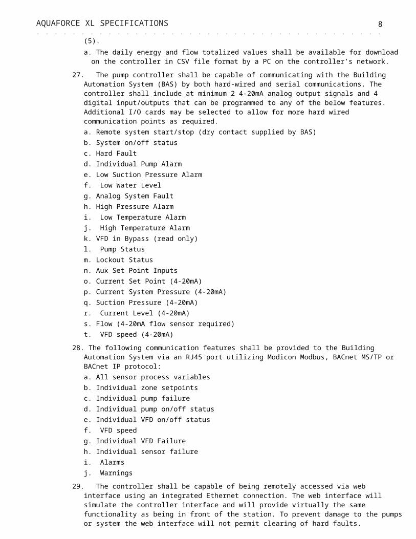
26.The HMI shall display easily readable tables of totalized values for energy and flow consumption across the previous day, weeks (5), months (12), years (5).a. The daily energy and flow totalized values shall be available for download on the
controller in CSV file format by a PC on the controller’s network.27.The pump controller shall be capable of communicating with the Building Automation
System (BAS) by both hard-wired and serial communications. The controller shall include at minimum 2 4-20mA analog output signals and 4 digital input/outputs that can be programmed to any of the below features. Additional I/O cards may be selected to allow for more hard wired communication points as required. a. Remote system start/stop (dry contact supplied by BAS)b. System on/off status c. Hard Faultd. Individual Pump Alarm e. Low Suction Pressure Alarmf. Low Water Levelg. Analog System Faulth. High Pressure Alarmi. Low Temperature Alarmj. High Temperature Alarmk. VFD in Bypass (read only)l. Pump Statusm. Lockout Status

AQUAFORCE XL SPECIFICATIONS 7. . . . . . . . . . . . . . . . . . . . . . . . . . . . . . . . . . . . . . . . . . . . . . . . . . . . . . . . . . . . . . . . . . . . . . . . . . . . . . . . . . . . . . . . . . . . . . . . n. Aux Set Point Inputs
o. Current Set Point (4-20mA)p. Current System Pressure (4-20mA)q. Suction Pressure (4-20mA)r. Current Level (4-20mA)s. Flow (4-20mA flow sensor required) t. VFD speed (4-20mA)
28. The following communication features shall be provided to the Building Automation System via an RJ45 port utilizing Modicon Modbus, BACnet MS/TP or BACnet IP protocol:a. All sensor process variablesb. Individual zone setpointsc. Individual pump failured. Individual pump on/off statuse. Individual VFD on/off statusf. VFD speedg. Individual VFD Failureh. Individual sensor failurei. Alarmsj. Warnings
29.The controller shall be capable of being remotely accessed via web interface using an integrated Ethernet connection. The web interface will simulate the controller interface and will provide virtually the same functionality as being in front of the station. To prevent damage to the pumps or system the web interface will not permit clearing of hard faults.
2.3.b. CENTRIPRO AQUAVAR VARIABLE FREQUENCY DRIVE1. Description
a. This specification covers complete variable frequency drives (VFDs) designated on the drawing schedules to be variable speed. All standard and optional features shall be included within the VFD panel.
b. The VFD shall be rated NEMA 1 or NEMA 12 as required on the schedule. The VFD shall have been evaluated by UL and found acceptable for mounting in a plenum or other air handling compartment. Manufacturer shall supply a copy of the UL plenum evaluation upon request.
c. The VFD shall be tested to UL 508C. The appropriate UL label shall be applied. When the VFDs are to be located in Canada, C-UL certifications shall apply. VFD shall be manufactured in ISO 9001, 2000 certified facilities.
d. The VFD shall be CE marked and conform to the European Union ElectroMagnetic Compatibility directive.
e. The VFD shall be UL listed for a short circuit current rating of 100 kA and labeled with this rating.
f. The VFD manufacturer shall supply the VFD and all necessary controls as herein specified.2. Components
a. The VFD shall convert incoming fixed frequency three-phase AC power into an adjustable frequency and voltage for controlling the speed of three-phase AC motors. The motor current shall closely approximate a sine wave. Motor voltage shall be varied with frequency to maintain desired motor magnetization current suitable for the driven load and to eliminate the need for motor de-rating.
b. When properly sized, the VFD shall allow the motor to produce full rated power at rated motor voltage, current, and speed without using the motor's service factor. VFDs utilizing sine weighted/coded modulation (with or without 3rd harmonic injection) must provide data verifying that the motors will not draw more than full load current during full load and full speed operation.
c. The VFD shall include an input full-wave bridge rectifier and maintain a fundamental (displacement) power factor near unity regardless of speed or load.
d. The VFD shall have a dual 5% impedance DC link reactor on the positive and negative rails of the DC bus to minimize power line harmonics and protect the VFD from power line
AQUAFORCE XL SPECIFICATIONS 8. . . . . . . . . . . . . . . . . . . . . . . . . . . . . . . . . . . . . . . . . . . . . . . . . . . . . . . . . . . . . . . . . . . . . . . . . . . . . . . . . . . . . . . . . . . . . . . . transients. The chokes shall be non-saturating. Swinging chokes that do not provide full
harmonic filtering throughout the entire load range are not acceptable. VFDs with saturating (non-linear) DC link reactors shall require an additional 3% AC line reactor to provide acceptable harmonic performance at full load, where harmonic performance is most critical.
e. The VFD’s full load output current rating shall meet or exceed NEC Table 430-150. The VFD shall be able to provide full rated output current continuously, 110% of rated current for 60 seconds and 120% of rated torque for up to 0.5 second while starting.
f. A programmable automatic energy optimization selection feature shall be provided standard in the VFD. This feature shall automatically and continuously monitor the motor’s speed and load to adjust the applied voltage to maximize energy savings.
g. Output power circuit switching shall be able to be accomplished without interlocks or damage to the VFD.
h. An automatic motor adaptation algorithm shall measure motor stator resistance and reactance to optimize performance and efficiency. It shall not be necessary to run the motor or de-couple the motor from the load to perform the test.
i. Galvanic isolation shall be provided between the VFD’s power circuitry and control circuitry to ensure operator safety and to protect connected electronic control equipment from damage caused by voltage spikes, current surges, and ground loop currents. VFDs not including either galvanic or optical isolation on both analog I/O and discrete digital I/O shall include additional isolation modules.
j. VFD shall minimize the audible motor noise through the use of an adjustable carrier frequency. The carrier frequency shall be automatically adjusted to optimize motor and VFD operation while reducing motor noise. VFDs with fixed carrier frequency are not acceptable.
3. Protective featuresa. A minimum of Class 20 I2t electronic motor overload protection for single motor
applications shall be provided. Overload protection shall automatically compensate for changes in motor speed.
b. Protection against input transients, loss of AC line phase, output short circuit, output ground fault, over voltage, under voltage, VFD over temperature and motor over temperature. The VFD shall display all faults in plain language. Codes are not acceptable.
c. Protect VFD from input phase loss. The VFD should be able to protect itself from damage and indicate the phase loss condition. During an input phase loss condition, the VFD shall be able to be programmed to either trip off while displaying an alarm, issue a warning while running at reduced output capacity, or issue a warning while running at full commanded speed. This function is independent of which input power phase is lost.
d. Protect from under voltage. The VFD shall provide full rated output with an input voltage as low as 90% of the nominal. The VFD will continue to operate with reduced output, without faulting, with an input voltage as low as 70% of the nominal voltage.
e. Protect from over voltage. The VFD shall continue to operate without faulting with a momentary input voltage as high as 130% of the nominal voltage.
f. The VFD shall incorporate a programmable motor preheat feature to keep the motor warm and prevent condensation build up in the motor when it is stopped in a damp environment by providing the motor stator with a controlled level of current.
g. VFD shall include a “signal loss detection” algorithm with adjustable time delay to sense the loss of an analog input signal. It shall also include a programmable time delay to eliminate nuisance signal loss indications. The functions after detection shall be programmable.
h. VFD shall function normally when the keypad is removed while the VFD is running. No warnings or alarms shall be issued as a result of removing the keypad.
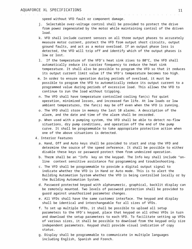
i. VFD shall catch a rotating motor operating forward or reverse up to full speed without VFD fault or component damage.
j. Selectable over-voltage control shall be provided to protect the drive from power regenerated by the motor while maintaining control of the driven load.
k. VFD shall include current sensors on all three output phases to accurately measure motor current, protect the VFD from output short circuits, output ground faults, and act as a motor overload. If an output phase loss is detected, the VFD will trip off and identify which

AQUAFORCE XL SPECIFICATIONS 9. . . . . . . . . . . . . . . . . . . . . . . . . . . . . . . . . . . . . . . . . . . . . . . . . . . . . . . . . . . . . . . . . . . . . . . . . . . . . . . . . . . . . . . . . . . . . . . . of the output phases is low or lost.
l. If the temperature of the VFD’s heat sink rises to 80°C, the VFD shall automatically reduce its carrier frequency to reduce the heat sink temperature. It shall also be possible to program the VFD so that it reduces its output current limit value if the VFD’s temperature becomes too high.
m. In order to ensure operation during periods of overload, it must be possible to program the VFD to automatically reduce its output current to a programmed value during periods of excessive load. This allows the VFD to continue to run the load without tripping.
n. The VFD shall have temperature controlled cooling fan(s) for quiet operation, minimized losses, and increased fan life. At low loads or low ambient temperatures, the fan(s) may be off even when the VFD is running.
o. The VFD shall store in memory the last 10 alarms. A description of the alarm, and the date and time of the alarm shall be recorded.
p. When used with a pumping system, the VFD shall be able to detect no-flow situations, dry pump conditions, and operation off the end of the pump curve. It shall be programmable to take appropriate protective action when one of the above situations is detected.
4. Interior Featuresa. Hand, Off and Auto keys shall be provided to start and stop the VFD and determine the
source of the speed reference. It shall be possible to either disable these keys or password protect them from undesired operation.
b. There shall be an “Info” key on the keypad. The Info key shall include “on-line” context sensitive assistance for programming and troubleshooting.
c. The VFD shall be programmable to provide a digital output signal to indicate whether the VFD is in Hand or Auto mode. This is to alert the Building Automation System whether the VFD is being controlled locally or by the Building Automation System.
d. Password protected keypad with alphanumeric, graphical, backlit display can be remotely mounted. Two levels of password protection shall be provided to guard against unauthorized parameter changes.
e. All VFDs shall have the same customer interface. The keypad and display shall be identical and interchangeable for all sizes of VFDs.
f. To set up multiple VFDs, it shall be possible to upload all setup parameters to the VFD’s keypad, place that keypad on all other VFDs in turn and download the setup parameters to each VFD. To facilitate setting up VFDs of various sizes, it shall be possible to download from the keypad only size independent parameters. Keypad shall provide visual indication of copy status.
g. Display shall be programmable to communicate in multiple languages including English, Spanish and French.
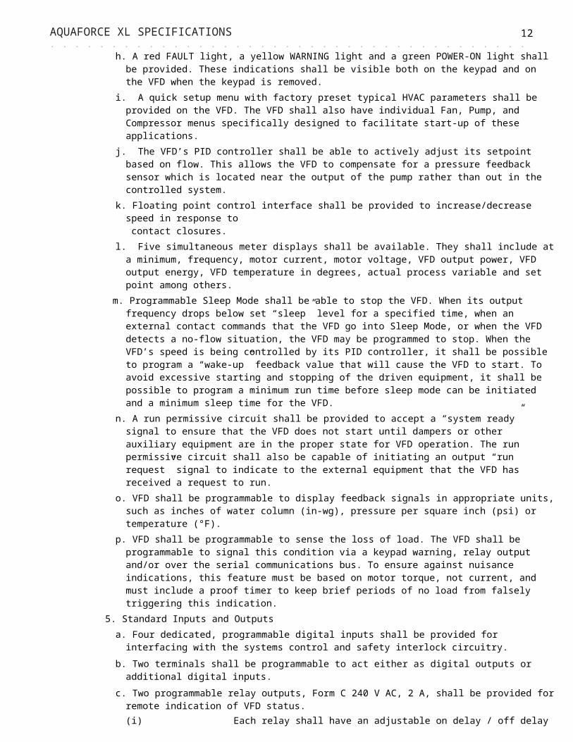
h. A red FAULT light, a yellow WARNING light and a green POWER-ON light shall be provided. These indications shall be visible both on the keypad and on the VFD when the keypad is removed.
i. A quick setup menu with factory preset typical HVAC parameters shall be provided on the VFD. The VFD shall also have individual Fan, Pump, and Compressor menus specifically designed to facilitate start-up of these applications.
j. The VFD’s PID controller shall be able to actively adjust its setpoint based on flow. This allows the VFD to compensate for a pressure feedback sensor which is located near the output of the pump rather than out in the controlled system.
k. Floating point control interface shall be provided to increase/decrease speed in response to contact closures.
l. Five simultaneous meter displays shall be available. They shall include at a minimum, frequency, motor current, motor voltage, VFD output power, VFD output energy, VFD temperature in degrees, actual process variable and set point among others.
m. Programmable Sleep Mode shall be able to stop the VFD. When its output frequency drops below set “sleep” level for a specified time, when an external contact commands that the VFD go into Sleep Mode, or when the VFD detects a no-flow situation, the VFD may be programmed to stop. When the VFD’s speed is being controlled by its PID controller, it shall be possible to program a “wake-up” feedback value that will cause the VFD to start.

AQUAFORCE XL SPECIFICATIONS 10. . . . . . . . . . . . . . . . . . . . . . . . . . . . . . . . . . . . . . . . . . . . . . . . . . . . . . . . . . . . . . . . . . . . . . . . . . . . . . . . . . . . . . . . . . . . . . . . To avoid excessive starting and stopping of the driven equipment, it shall be possible to
program a minimum run time before sleep mode can be initiated and a minimum sleep time for the VFD.
n. A run permissive circuit shall be provided to accept a “system ready” signal to ensure that the VFD does not start until dampers or other auxiliary equipment are in the proper state for VFD operation. The run permissive circuit shall also be capable of initiating an output “run request” signal to indicate to the external equipment that the VFD has received a request to run.
o. VFD shall be programmable to display feedback signals in appropriate units, such as inches of water column (in-wg), pressure per square inch (psi) or temperature (°F).
p. VFD shall be programmable to sense the loss of load. The VFD shall be programmable to signal this condition via a keypad warning, relay output and/or over the serial communications bus. To ensure against nuisance indications, this feature must be based on motor torque, not current, and must include a proof timer to keep brief periods of no load from falsely triggering this indication.
5. Standard Inputs and Outputsa. Four dedicated, programmable digital inputs shall be provided for interfacing with the
systems control and safety interlock circuitry. b. Two terminals shall be programmable to act either as digital outputs or additional digital
inputs. c. Two programmable relay outputs, Form C 240 V AC, 2 A, shall be provided for remote
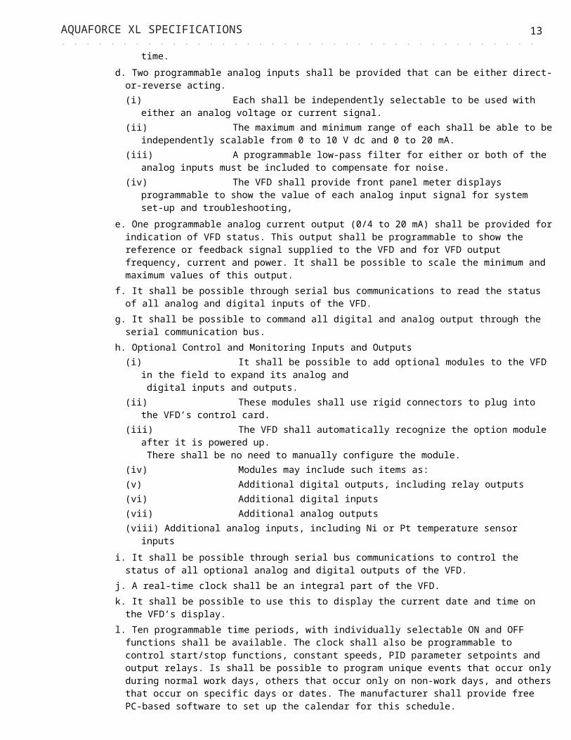
indication of VFD status. (i) Each relay shall have an adjustable on delay / off delay time.
d. Two programmable analog inputs shall be provided that can be either direct-or-reverse acting.(i) Each shall be independently selectable to be used with either an analog voltage or
current signal.(ii) The maximum and minimum range of each shall be able to be independently scalable
from 0 to 10 V dc and 0 to 20 mA.(iii)A programmable low-pass filter for either or both of the analog inputs must be included
to compensate for noise.(iv)The VFD shall provide front panel meter displays programmable to show the value of
each analog input signal for system set-up and troubleshooting,e. One programmable analog current output (0/4 to 20 mA) shall be provided for indication
of VFD status. This output shall be programmable to show the reference or feedback signal supplied to the VFD and for VFD output frequency, current and power. It shall be possible to scale the minimum and maximum values of this output.
f. It shall be possible through serial bus communications to read the status of all analog and digital inputs of the VFD.
g. It shall be possible to command all digital and analog output through the serial communication bus.
h. Optional Control and Monitoring Inputs and Outputs(i) It shall be possible to add optional modules to the VFD in the field to expand its analog
and digital inputs and outputs.
(ii) These modules shall use rigid connectors to plug into the VFD’s control card.(iii) The VFD shall automatically recognize the option module after it is powered up.
There shall be no need to manually configure the module.(iv) Modules may include such items as:(v) Additional digital outputs, including relay outputs(vi) Additional digital inputs(vii) Additional analog outputs(viii) Additional analog inputs, including Ni or Pt temperature sensor inputs
i. It shall be possible through serial bus communications to control the status of all optional analog and digital outputs of the VFD.
AQUAFORCE XL SPECIFICATIONS 11. . . . . . . . . . . . . . . . . . . . . . . . . . . . . . . . . . . . . . . . . . . . . . . . . . . . . . . . . . . . . . . . . . . . . . . . . . . . . . . . . . . . . . . . . . . . . . . . j. A real-time clock shall be an integral part of the VFD.
k. It shall be possible to use this to display the current date and time on the VFD’s display. l. Ten programmable time periods, with individually selectable ON and OFF functions shall be
available. The clock shall also be programmable to control start/stop functions, constant speeds, PID parameter setpoints and output relays. Is shall be possible to program unique events that occur only during normal work days, others that occur only on non-work days, and others that occur on specific days or dates. The manufacturer shall provide free PC-based software to set up the calendar for this schedule.
m. All VFD faults shall be time stamped to aid troubleshooting.n. It shall be possible to program maintenance reminders based on date and time, VFD
running hours, or VFD operating hours.o. The real-time clock shall be able to time and date stamp all faults recorded in the VFD
fault log.p.The VFD shall be able to store load profile data to assist in analyzing the system demand
and energy consumption over time.q.The VFD shall include a sequential logic controller to provide advanced control interface
capabilities. This shall include:(i) Comparators for comparing VFD analog values to programmed trigger values(ii) Logic operators to combine up to three logic expressions using Boolean algebra(iii)Delay timers(iv)A 20-step programmable structure
r. The VFD shall include a Cascade Controller which allows the VFD to operate in closed loop set point (PID) control mode one motor at a controlled speed and control the operation of 3 additional constant speed motor starters.
6. Serial Communicationsa. The VFD shall include a standard EIA-485 communications port and capabilities to be
connected to the following serial communication protocols at no additional cost and without a need to install any additional hardware or software in the VFD:(i) Modbus RTU
b. VFD shall have standard USB port for direct connection of Personal Computer (PC) to the VFD. The manufacturer shall provide no-charge PC software to allow complete setup and access of the VFD and logs of VFD operation through the USB port. It shall be possible to communicate to the VFD through this USB port without interrupting VFD communications to the building management system.
c. The VFD shall have provisions for an optional 24 V DC back-up power interface to power the VFD’s control card. This is to allow the VFD to continue to communicate to the building automation system even if power to the VFD is lost.
7. Adjustmentsa. The VFD shall have a manually adjustable carrier frequency that can be adjusted in 0.5
kHz increments to allow the user to select the desired operating characteristics. The VFD shall also be programmable to automatically reduce its carrier frequency to avoid tripping due to thermal loading.
b. Four independent setups shall be provided.c. Four preset speeds per setup shall be provided for a total of 16. d. Each setup shall have two programmable ramp up and ramp down times. Acceleration
and deceleration ramp times shall be adjustable over the range from 1 to 3,600 seconds. e. Each setup shall be programmable for a unique current limit value. If the output current
from the VFD reaches this value, any further attempt to increase the current produced by the VFD will cause the VFD to reduce its output frequency to reduce the load on the VFD. If desired, it shall be possible to program a timer which will cause the VFD to trip off after a programmed time period.
f. If the VFD trips on one of the following conditions, the VFD shall be programmable for automatic or manual reset: external interlock, under-voltage, over-voltage, current limit, over temperature, and VFD overload.
AQUAFORCE XL SPECIFICATIONS 12. . . . . . . . . . . . . . . . . . . . . . . . . . . . . . . . . . . . . . . . . . . . . . . . . . . . . . . . . . . . . . . . . . . . . . . . . . . . . . . . . . . . . . . . . . . . . . . . g. The number of restart attempts shall be selectable from 0 through 20 or infinitely and the
time between attempts shall be adjustable from 0 through 600 seconds.h. An automatic “start delay” may be selected from 0 to 120 seconds. During this delay
time, the VFD shall be programmable to either apply no voltage to the motor or apply a DC braking current if desired.
i. Four programmable critical frequency lockout ranges to prevent the VFD from operating the load at a speed that causes vibration in the driven equipment shall be provided. Semi-automatic setting of lockout ranges shall simplify the set-up.
8. Service Conditionsa. Ambient temperature, continuous, full speed, full load operation:
(i) -10 to 45°C (14 to 113°F) through 125 HP @ 460 and 600 volt, through 60 HP @ 208 volt
(ii) -10 to 40°C (14 to 104°F) 150 HP and largerb. 0 to 95% relative humidity, non-condensing.c. Elevation to 3,300 feet without derating.d. AC line voltage variation, -10 to +10% of nominal with full output.e. No side clearance shall be required for cooling.f. All power and control wiring shall be done from the bottom.g. All VFDs shall be plenum rated.
9. Quality Assurancea. To ensure quality, the complete VFD shall be tested by the manufacturer. The VFD shall
drive a motor connected to a dynamometer at full load and speed and shall be cycled during the automated test procedure.
10. VFD shall utilize a full wave rectifier to convert three phase AC to a fixed DC voltage. Power factor shall remain above 0.98 regardless of speed or load. VFD’s employing power factor correction capacitors shall not be acceptable.
11. An internal line reactor (5% impedance) shall be provided to lower harmonic distortion of the power line and to increase the fundamental power factor.
12.The VFD shall be suitable for elevations to 3300 feet above sea level without derating. Maximum operating ambient temperature rating shall not be greater than 104°F. VFD shall be suitable for operation in environments up to 95% non-condensing humidity.
13.The VFD shall be capable of displaying the following information in plain English via an alphanumeric display:a. Output Frequencyb. Output Voltagec. Motor Currentd. Kilowatts per houre. Fault identification with textf. Percent torqueg. Percent powerh. RPM
14.The VFD shall have the ability to automatically restart after an over-current, overvoltage, under-voltage, or loss of input signal protective trip. The number of restart attempts, trial time, and time between reset attempts shall be programmable.
15.Three (3) programmable critical frequency lockout ranges to prevent the VFD from operating the load continuously at an unstable speed.
16.Operator Control Panel (Keypad)a. Each VFD shall be equipped with a front mounted operator control panel (keypad)
consisting of a backlit, alphanumeric, graphic display and a keypad with keys for Start/Stop, Local/Remote, Up/Down and Help. Two (2) Softkeys will be provided which change functionality depending upon the position within the parameter hierarchy or state of panel.
AQUAFORCE XL SPECIFICATIONS 13. . . . . . . . . . . . . . . . . . . . . . . . . . . . . . . . . . . . . . . . . . . . . . . . . . . . . . . . . . . . . . . . . . . . . . . . . . . . . . . . . . . . . . . . . . . . . . . . b.All parameter names, fault messages, warnings and other information shall be displayed
in complete English words or Standard English abbreviations to allow the user to understand what is being displayed without the use of a manual or cross-reference table.
c. The Display shall have contrast adjustment provisions to optimize viewing at any angle. d. The control panel shall provide a real time clock for time stamping events and fault
conditions. e. The control panel shall include a feature for uploading parameter settings to control panel
memory and downloading from the control panel to the same Drive or to another Drive. f. All Drives throughout the entire power range shall have the same customer interface,
including digital display, and keypad, regardless of horsepower rating. g.The keypad shall be able to be installed or removed from the drive while it is powered,
capable of remote mounting, and shall have its own non-volatile memory. 17.Protective Functions
a. For each programmed warning and fault protection function, the Drive shall display a message in complete English words or Standard English abbreviations. The three (3) most recent fault messages along with time, current, speed, voltage, frequency and DI Status shall be stored in the Drive’s fault history. The last ten (10) fault names shall be stored in Drive memory.
b. The Drive shall include internal MOV’s for phase to phase and phase to ground line voltage transient protection.
c. Output short circuit withstand rating and ground fault protection rated for 100,000 AIC shall be provided per UL508C without relying on line fuses. Motor phase loss protection shall be provided.
d. The Drive shall provide electronic motor overload protection qualified per UL508C. e. Protection shall be provided for AC line or DC bus overvoltage at 130% of maximum rated
or under voltage at 65% of min. rated and input phase loss. f. A power loss ride through feature will allow the Drive to remain fully operational after
losing power as long as kinetic energy can be recovered from the rotating mass of the motor and load.
18. Integrated Drive Disconnectsa. 3-Phase: Individual integrated drive fused disconnects shall have exterior operators.b. Single-Phase: Individual integrated drive disconnects shall have exterior operators and
external fusing.19. Variable Speed System Sequence of Operation
a. The system shall consist of a PACE XL pump logic controller with multi-pump parallel operation control, duty-standby pump selection, automatic alternation and automatic transfer to the standby pump upon pump/VFD failure.
b. The pumping system shall start upon the closure of customer's contact when the pump logic controller Mode of Operation is in REMOTE.
c. When the pump logic controller mode in LOCAL, the pumping system shall operate automatically. d. Each sensor/transmitter shall send a 4-20mA signal to the PACE XL pump logic controller, indicative of process variable condition.
e. When the set point is satisfied by the process variable, the pump speed shall remain constant at the optimum energy consumption level.
f. When the process variable exceeds the allowable drift from the set point for a set time the pump controller shall automatically start the next lag pump and continue in this fashion as necessary to satisfy system demand. To maintain system set point the controller will operate the pumps synchronously or sequentially to ensure maximum energy conservation.
g. As demand is satisfied, the controller shall automatically stop lag pumps as necessary to conserve energy.
h. In the event of a pump failure or a VFD fault, the pump logic controller automatically initiates a timed sequence of operation to start the redundant pump/VFD set in the variable speed mode.
i. In the event of the failure of a zone sensor/transmitter, its process variable signal shall be removed from the scan/compare program. The redundant zone sensor/transmitters, if

AQUAFORCE XL SPECIFICATIONS 14. . . . . . . . . . . . . . . . . . . . . . . . . . . . . . . . . . . . . . . . . . . . . . . . . . . . . . . . . . . . . . . . . . . . . . . . . . . . . . . . . . . . . . . . . . . . . . . . available, shall remain in the scan/compare program for control.
j. PUMP or VFD hard fault shall be flash continuously on the display on the operator interface of the pump logic controller until the fault has been corrected and the controller has been manually reset.
k. When the system is satisfied, the pump controller shall shut down the single running lead pump without the need of a flow sensor/switch or hydropneumatic tank and enter energy saving / no flow shutdown mode.
2.3.c. MECHANICAL1. Pump Station Frame and Piping
a. Framing shall be designed and fabricated to provide structural support for all attached equipment, and provide anchor bolt support. The base shall supply sufficient rigidity to withstand the stresses of reasonable and competent transportation to site, off loading, installation, and operation.
b. Piping shall be constructed from 304 stainless steel, schedule 10 or heavier pipe as required to maintain a 3 to 1 pressure safety factor (including 1/16” corrosion allowance).
2. Stainless Steel Vertical Multistage Pumpsa. Goulds Water Technology’s e-SV vertical multistage pump, compliant to ANSI/NSF-61
Annex G, premium efficient motor - standard NEMA design 56C, JM, or TC frame.b.AISI 304 wetted componentsc. Impeller: AISI 304d.Diffuser: AISI 304e. Shaft: AISI 316 (sizes 1 – 22SV) • Duplex ASTM-A182 (sizes 33-92SV)f. External sleeve: AISI 304g.Pump body: AISI 304 h.Seal housing: AISI 304 i. Mechanical seal: all material options NSF/ANSI-61 compliant
3. Centrifugal Pumpsa. Goulds Water Technology NPE or SSH end suction pumpb. 316L constructionc. Premium efficient 3-PH motor, ODP or TEFC enclosure. NEMA design T-frame or JM.
4. Isolation Ball Valvesa. Isolation ball valves shall be certified to NSF-61 for use with potable drinking water.b. Isolation ball valves shall be certified as low lead having wetted surface area with a
weighted average lead content < 0.25%.c. Valves shall be rated for 600 psi WOG / 150 psi WSP for valves ¼” to 2” and 400 psi
WOG / 125 psi WSP for valves 2-1/2” to 4”. d. Seats and stem packing shall be virgin PTFE. Stem shall be bottom loaded blowout proof
design with fluorocarbon elastomer O-ring to prevent stem leaks.e. Valves shall be 2-piece full port design.
5. Isolation Grooved Butterfly Valvesa. Valves shall be certified to NSF-61 for use with potable drinking water.b. Valve bodies shall be nylon coated ductile iron conforming to ASTM A536 with integral
neck and ISO mounting top. c. The disc shall be encapsulated with Gr. E EPDM for cold and hot water services.d. Valves shall be rated for 300 psi CWP
6. Isolation Lug Style Butterfly Valvea. Valve shall be certified to NSF-61 for use with potable drinking water.

AQUAFORCE XL SPECIFICATIONS 15. . . . . . . . . . . . . . . . . . . . . . . . . . . . . . . . . . . . . . . . . . . . . . . . . . . . . . . . . . . . . . . . . . . . . . . . . . . . . . . . . . . . . . . . . . . . . . . . b. Valve body shall be made of ASTM 536 ductile iron and will be coated with an FDA
approved epoxy. Valve face to face dimensions shall comply with API 609 and MSS-SP-67.c. Disc shall be made of ASTM A-351 stainless steel. Shaft shall be made of 316SS.d. Bushing shall be made of a Teflon®-Darcon inner liner bonded to fiberglass-epoxy resin
outer shell.e. Seat shall be EPDM.f. Valve shall be rated to 200 psi WOG.
7. Threaded Check Valvesa. All valve metallic components shall be 316SS.b. Seat shall be Viton.c. Valve shall be rated for 400 psi WOG.
8. Wafer Style Silent Check Valvea. The valve body shall be constructed of ASTM A126 Class B cast iron for Class 125/250
(lead free). b. The seat and double guided disc shall be ASTM B584, C87600 silicon bronze.c. The compression spring shall be ASTM A313 Type 316 Stainless Steel.d. NSF/ANSI 61 & 372 certificatione. The valve design shall incorporate a center guided, spring loaded disc, guided at opposite
ends and having a short linear stroke that generates a flow area equal to the nominal valve size.
f. The operation of the valve shall not be affected by the position of installation. The valve shall be capable of operating in the horizontal or vertical positions with the flow up or down.
g. All component parts shall be field replaceable without the need of special tools. A replaceable guide bushing shall be provided and held in position by the spring. The spring shall be designed to withstand 100,000 cycles without failure and provide a cracking pressure of 0.5 psi.
h. The valve disc shall be concave to the flow direction providing for disc stabilization, maximum strength, and a minimum flow velocity to open the valve.
i. The valve disc and seat shall have a seating surface finish of 16 micro-inch or better to ensure positive seating at all pressures. The leakage rate shall not exceed the allowable rate for metal seated valves allowed by AWWA Standard C508 or 1 oz (30 ml) per hour per inch (mm) of valve diameter.
j. The valve flow way shall be contoured and unrestricted to provide full flow areas at all locations within the valve. Cv flow coefficients shall be equal to or greater than specified below and verified by an independent testing laboratory.
k. The valves shall be hydrostatically tested at 1.5 times their rated cold working pressure and seat tested at the valve CWP.
Valve Size Inches (mm)
Wafer Style Cv
2 (50) 43
2.5 (65) 88
3 (80) 130
4 (100) 228
5 (125) 350
6 (150) 520

AQUAFORCE XL SPECIFICATIONS 16. . . . . . . . . . . . . . . . . . . . . . . . . . . . . . . . . . . . . . . . . . . . . . . . . . . . . . . . . . . . . . . . . . . . . . . . . . . . . . . . . . . . . . . . . . . . . . . . 9. Sensor / Transmitters
a. Pressure transducer shall be utilized for providing all pressure signals for the pump control logic. Pressure transducer shall be a solid-state bonded strain gage type with an accuracy of < ±0.5% BFSL and constructed of 316 stainless steel. Transducer shall be rated for a pressure of 300 psi and shall provide gauge pressure output, rather than an absolute. Pressure transducer constructed of plastic is not acceptable. Pressure transducer shall be 4-20mA analog type with 10-28 VDC supply range, shall utilize a packard type connector to prevent moisture intrusion, and include surge protection to protect against voltage spikes.
10. Flowmetera. Provide a Bell & Gossett ST-104 field mounted flow sensor transmitter as indicated on the
plans. Unit shall transmit an isolated 4-20 mA dc signal indicative of process variable to the pump logic controller via standard two wire 24 VDC system. Unit shall consist of an insertion probe and separately mounted transmitter. The unit shall be accurate to within 1% of flow rate from 1 to 30 fps and shall withstand a static pressure of 200 PSI with negligible change in output.
11. Pressure Gaugesa. Gauges shall be provided for the suction and discharge manifold.b. Accuracy shall be ±1.5%c. Bourdon tube and connection shall be constructed of 316SS.d. Case, bezel and internals shall be constructed of 316SS.e. Gauge shall be filled with glycerin in order to dampen pulsation and vibration and to
provide lubrication to the internal parts. f. Gauge range shall be selected to cover the largest operating range for the specific
conditions and pump selected.
12. Flange Boltsa. Bolts shall be zinc plated and shall meet ASTM Grade A193 B7.
13. Painta. Standard finish coat shall be acrylic enamel to a thickness of no less than 3 mils.
PART 3 EXECUTION 3.1 INSTALLATION
Install equipment in accordance with manufacturer's instructions.The contractor shall align the pump and motor shafts to within the manufacturer's recommended tolerances prior to system start-up.Power wiring, as required, shall be the responsibility of the electrical contractor. All wiring shall be performed per manufacturer’s instructions and applicable state, federal and local codes.Control wiring for remote mounted switches and sensor / transmitters shall be the responsibility of the controls contractor. All wiring shall be performed per manufacturer’s instructions and applicable state, federal and local codes.
3.2 DEMONSTRATION/TRAININGThe system manufacturer’s factory qualified representative shall be capable of providing optional start-up of the packaged pumping system. This start-up shall include verification of proper installation, system initiation, adjustment and fine tuning. Start-up shall not be considered complete until the sequence of operation, including all alarms, has been sufficiently demonstrated to the owner or owner's designated representative. This job site visit shall occur only after all hook-ups, tie-ins, and terminations have been completed and signed-off on the manufacturer's start-up request form.The system manufacturer’s factory qualified representative shall be capable of providing on-site training for owner's personnel. This training shall fully cover maintenance and operation of all

AQUAFORCE XL SPECIFICATIONS 17. . . . . . . . . . . . . . . . . . . . . . . . . . . . . . . . . . . . . . . . . . . . . . . . . . . . . . . . . . . . . . . . . . . . . . . . . . . . . . . . . . . . . . . . . . . . . . . . system components.
The system manufacturer must have an optional complete pressure booster training program available for owner's personnel. The training sessions shall take place at the manufacturer's facility and cover all aspects of pressure booster system design, service and operation.
3.3 WARRANTYThe manufacturer shall warrant the water pumping system to be free of defects in material and workmanship for one year (12 months) from date of authorized start-up, not to exceed eighteen (18) months from date of manufacturer’s invoice. Complete terms and conditions will be provided upon request. The complete VFD shall be warranted by the manufacturer for a period of 30 months from date of shipment. The warranty shall include parts, labor, travel costs and living expenses incurred by the manufacturer to provide factory authorized on-site service. The warranty shall be provided by the VFD manufacturer and not a third party. A written warranty statement shall be provided with the submittals.The manufacturer shall offer an optional, extended warranty allowing the VFD warranty to be extended to up to 6 years.
3.4 START-UP SERVICEOwner start up assistance will be provided by a manufacturer qualified representative and will be limited to one 8-hour day, unless previously negotiated by the factory representative. When discharge piping, electrical connections, and electrical inspection have been completed, the pump station representative shall be contacted for start up. A minimum two-week notice shall be given to the manufacturer qualified representative prior to scheduled start up date. During start up, the complete pumping system shall be given a running test of normal start and stop, and fully loaded operating conditions. During this test, each pump shall demonstrate its ability to operate without undue vibration, or overheating, and shall demonstrate its general fitness for service. All defects shall be corrected and adjustments shall be made to the pumping station for satisfactory operation. System problems or concerns will be corrected by the general contractor or site station staff, in conjunction with the appropriate factory qualified representative. Testing shall be repeated until satisfactory results are obtained, as determined by the engineer.

Xylem1) The tissue in plants that brings water upward from the roots;2) a leading global water technology company.
We’re a global team unified in a common purpose: creating innovative solutions to meet our world’s water needs. Developing new technologies that will improve the way water is used, conserved, and re-used in the future is central to our work. We move, treat, analyze, and return water to the environment, and we help people use water efficiently, in their homes, buildings, factories and farms. In more than 150 countries, we have strong, long-standing relationships with customers who know us for our powerful combination of leading product brands and applications expertise, backed by a legacy of innovation.
For more information on how Xylem can help you, go to www.xyleminc.com
Xylem Inc.http://www.gouldswatertechnology.com
Goulds is a registered trademark of Goulds Pumps, Inc. and is used under license.
© 2016 Xylem Inc. AQUAFXLSPEC R2 November 2016