VideoRaid RTR / RTRX VideoRaid FCR2 / FCR2X...
49
1 VideoRaid RTR / RTRX VideoRaid FCR2 / FCR2X Installation Guide Medea Corporation Technical Support Voice: (818) 880-0303 Fax: (818) 880-6906 [email protected] www.medea.com Document 103084-06 RevB July 5, 2005
Transcript of VideoRaid RTR / RTRX VideoRaid FCR2 / FCR2X...

1
VideoRaid RTR / RTRX VideoRaid FCR2 / FCR2X
Installation Guide
Medea Corporation Technical Support Voice: (818) 880-0303 Fax: (818) 880-6906 [email protected]
www.medea.com
Document 103084-06 RevB July 5, 2005

2

3

4
5

6
TABLE OF CONTENTS
Subject Page
I. Introduction 7 A. About VideoRaid RTR 7 B. About VideoRaid RTRX 7 C. About VideoRaid FCR2 7 D. About VideoRaid FCR2X 7 E. Fail-Safe and Real-Time Design 7 F. Multi-Stream Technology 7 II. Workstation Requirements 8 A. VideoRaid RTR/RTRX 8 B. VideoRaid FCR2/FCR2X 8 III. What’s in the Box 8 IV. VideoRaid RTR/FCR2 Technical Specifications 9 V. VideoRaid RTR/FCR2 Safety Precautions 10 VI. Finding Your Way Around VideoRaid 11 VII. VideoRaid Operational Features 13 A. Front Panel Indicators 13 B. Disk Drive Status Indicators 13 C. RAID Controller Status Indicators 13 D. Power Supply Status Indicators 13 E. Disk Drive Module Replacement 14 F. RAID Controller Module Replacement 15 G. Power Supply Module Replacement 15 H. VideoRaid Activity Lights 16 I. VideoRaid RTRX/FCR2X Physical Configuration 16 J. Installation of EMI Shield 17 VIII. Attaching VideoRaid to Your Workstation 18 A. VideoRaid RTR Configuration 18 B. VideoRaid FCR2 Configuration 20 C. VideoRaid RTRX Single Channel Configuration 21 D. VideoRaid RTRX Dual Channel Striped Configuration 23 E. VideoRaid FCR2X Single Channel Configuration 24 F. VideoRaid FCR2X Dual Channel Striped Configuration 26 IX. Initializing VideoRaid 27 A. Configuring VideoRaid for Formatting 27 B. Formatting VideoRaid 28 C. Single Channel Configuration – Windows 28 D. Single Channel Configuration – Mac OS X 34 E. Striping VideoRaid Channels – Windows 37 F. Striping VideoRaid Channels – Mac OS X 44 G. Downloading VideoRaid Firmware on your PC 47 H. Downloading VideoRaid Firmware on your Mac 48 X. Technical Support 49 XI. 3-Year Limited Warranty 49

7
I. INTRODUCTION Congratulations on your purchase of a VideoRaid disk array for content creation applications. Whether it’s VideoRaid RTR, VideoRaid RTRX, VideoRaid FCR2 or VideoRaid FCR2X, you’ve selected a storage solution that will protect your valuable data while offering unbeatable price/performance with the best warranty and support in the industry. A. About VideoRaid RTR VideoRaid RTR desktop disk arrays feature a high-performance Ultra160 SCSI interface and are the ideal storage solution for all content creation applications including animation, special effects, and non-linear video editing. B. About VideoRaid RTRX VideoRaid RTRX disk arrays can be set up in either a desktop or rack mountable configuration with a single or dual-channel Ultra160 SCSI interface. C. About VideoRaid FCR2 VideoRaid FCR2 desktop disk arrays feature a high-performance 2-Gbit fibre channel interface and are ideal for point-to-point applications or for building low-cost storage area networks (SAN) for workgroups. D. About VideoRaid FCR2X VideoRaid FCR2X disk arrays can be set up in either a desktop or rack mountable configuration and feature a single or dual-channel 2-Gbit fibre channel interface. NOTE: Throughout this manual, VideoRaid refers to VideoRaid RTR, VideoRaid RTRX, VideoRaid FCR2 and VideoRaid FCR2X.
E. Fail-Safe and Real-Time Design Medea’s real-time RAID controllers ensure that VideoRaid RTR/RTRX and VideoRaid FCR2/FCR2X disk arrays will continue to operate with no loss of data and with no degradation in performance in the unlikely event of a disk drive failure. If it becomes necessary to replace a faulty disk drive, simply insert a new drive module and the array will automatically begin to reconstruct the data that should be on that drive, and will do so in the background while you continue to work. When reconstruction is completed, VideoRaid will return to the fail-safe mode and resume the protection of your valuable data. F. Multi-Stream Technology (MST™) VideoRaid disk arrays are optimized with Medea’s proprietary Multi-Stream Technology (MST). MST is a sophisticated caching algorithm that utilizes VideoRaid’s on-board cache to support playback of multiple streams of uncompressed video in real-time.

8
II. WORKSTATION REQUIREMENTS A. VideoRaid RTR/RTRX 1. Medea qualified single or dual-channel Ultra 160 SCSI host adapter 2. Windows 2000/2003 Server/XP/XP Pro, Mac OS X B. VideoRaid FCR2/FCR2X 1. Medea qualified single or dual-channel 2Gbit fibre channel host adapter 2. Windows 2000/2003 Server/XP/XP Pro, Mac OS X, IRIX
III. WHAT’S IN THE BOX Take a moment to ensure that the following items are included in the shipping carton. If anything is missing, please call Medéa at (818) 880-0303. Please keep the shipping container and packing materials. In the unlikely event that you need to return the product to us for any reason, you must use the Medéa shipping container. If the product is returned to Medea and received damaged through improper packaging or handling, the warranty will be void and liability will rest with the user.
Contents for VideoRaid RTR: Contents for VideoRaid FCR2: • Compact desktop enclosure • Compact desktop enclosure • Five (5) removable drive modules • Five (5) removable drive modules • Removable Ultra160 SCSI RAID controller • Removable 2-Gbit FC RAID controller • Removable 200 W power supply • Removable 200 W power supply • 6 foot, VHD to VHD SCSI cable • Null modem cable • VHD SCSI LVD terminator • EMI Shield • Null modem cable • Power cord • EMI Shield • Installation Guide • Power cord • Installation Guide

9
Contents for VideoRaid RTRX: Contents for VideoRaid FCR2X • 19”, 3U rack mountable enclosure • 19”, 3U rack mountable enclosure • Up to ten (10) removable drive modules • Up to ten (10) removable drive modules • One (1) or two (2) removable U160 SCSI • One (1) or two (2) removable 2-Gbit FC RAID controller(s) RAID controller(s) • One (1) or two (2) removable 200 W • One (1) or two (2) removable 200 W power supplies power supplies • One (1) or Two (2) 6 foot, VHD to VHD • Null modem cable SCSI cables • Two (2) rack mount brackets and screws • One (1) or (2) VHD SCSI LVD terminators • Four (4) rubber feet and screws • Null modem cable • One (1) or two (2) EMI Shields • Two (2) rack mount brackets and screws • One (1) or two (2) power cords • Four (4) rubber feet and screws • Installation Guide • One (1) or two (2) EMI Shields • One (1) or two (2) power cords • Installation Guide
IV. VideoRaid RTR/FCR2 TECHNICAL SPECIFICATIONS Connectors:
VideoRaid RTR/RTRX VideoRaid FCR2/FCR2X Desktop: Two (2) VHD, 68-pin FCR2
Four (4) HSSDC, copper Built-in 4-port hub
or Four (4) LC, optical Built-in 4-port hub
or Two (2) LC optical and Two (2) HSSDC, copper Built-in 4-port hub
Rack Mount 5-Drive: Two (2) VHD, 68-pin FCR2X – 5-drive Four (4) HSSDC, copper Built-in 4-port hub
or Four (4) LC, optical Built-in 4-port hub
or Two (2) LC, optical and Two (2) HSSDC, copper Built-in 4-port hub
10
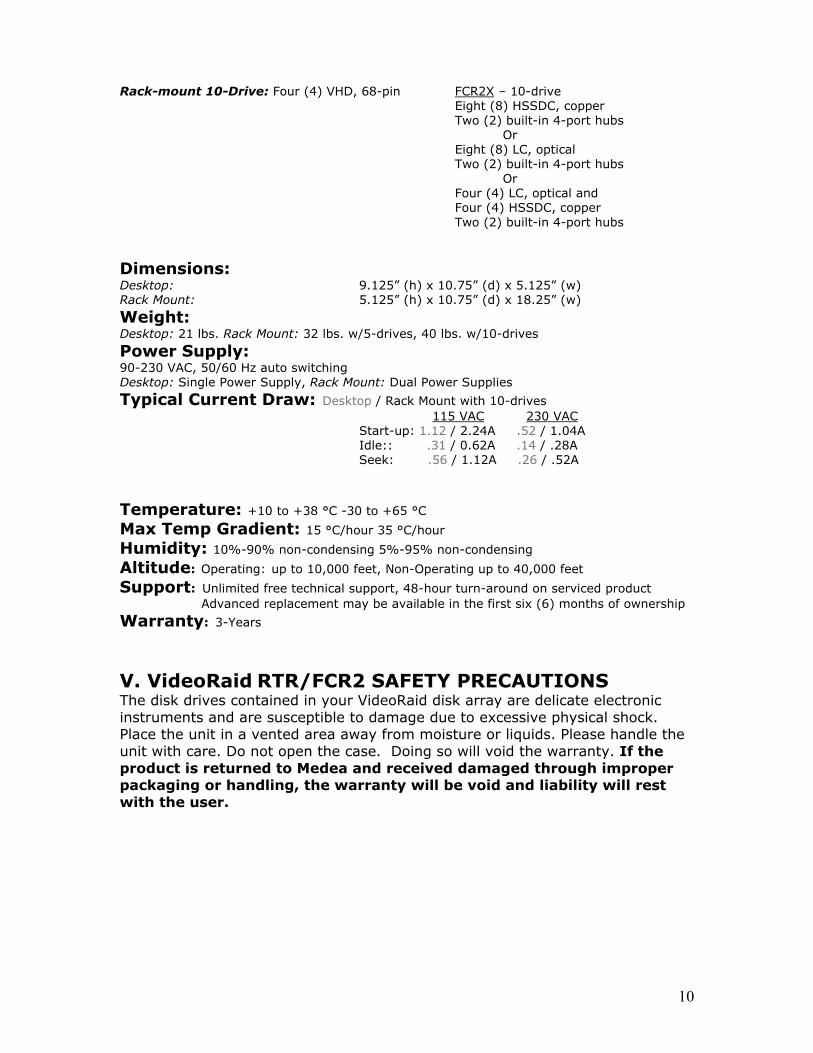
Rack-mount 10-Drive: Four (4) VHD, 68-pin FCR2X – 10-drive Eight (8) HSSDC, copper
Two (2) built-in 4-port hubs Or
Eight (8) LC, optical Two (2) built-in 4-port hubs Or Four (4) LC, optical and Four (4) HSSDC, copper Two (2) built-in 4-port hubs
Dimensions: Desktop: 9.125” (h) x 10.75” (d) x 5.125” (w) Rack Mount: 5.125” (h) x 10.75” (d) x 18.25” (w)
Weight: Desktop: 21 lbs. Rack Mount: 32 lbs. w/5-drives, 40 lbs. w/10-drives Power Supply: 90-230 VAC, 50/60 Hz auto switching Desktop: Single Power Supply, Rack Mount: Dual Power Supplies
Typical Current Draw: Desktop / Rack Mount with 10-drives 115 VAC 230 VAC
Start-up: 1.12 / 2.24A .52 / 1.04A Idle:: .31 / 0.62A .14 / .28A Seek: .56 / 1.12A .26 / .52A
Temperature: +10 to +38 °C -30 to +65 °C Max Temp Gradient: 15 °C/hour 35 °C/hour Humidity: 10%-90% non-condensing 5%-95% non-condensing Altitude: Operating: up to 10,000 feet, Non-Operating up to 40,000 feet Support: Unlimited free technical support, 48-hour turn-around on serviced product
Advanced replacement may be available in the first six (6) months of ownership
Warranty: 3-Years Environmental Specifications Operating Non-Operating
V. VideoRaid RTR/FCR2 SAFETY PRECAUTIONS The disk drives contained in your VideoRaid disk array are delicate electronic instruments and are susceptible to damage due to excessive physical shock. Place the unit in a vented area away from moisture or liquids. Please handle the unit with care. Do not open the case. Doing so will void the warranty. If the product is returned to Medea and received damaged through improper packaging or handling, the warranty will be void and liability will rest with the user.

11
VI. FINDING YOUR WAY AROUND VIDEORAID Desktop Arrays
Front Rear

12
Front
Rear
Rack-Mountable Arrays

13
VII. VideoRaid OPERATIONAL FEATURES The VideoRaid‘s on-board RAID controller offers true real-time performance and provides data protection in the event of a disk drive failure. It also provides the interface bridge between the PATA disk drives and the host interface.
A. Front Panel Indicators The “health” of a VideoRaid disk array is indicated by the STATUS indicator located on the front bezel of the unit directly under the POWER indicator as shown on the previous page. NOTE: Each “populated” channel of VideoRaid RTRX and VideoRaid FCR2X has its own dedicated STATUS and POWER indicators.
The STATUS indicator has four states as described below: GREEN (solid) – System OK AMBER (flashing) – Disk drive rebuild in progress. RED (flashing) – A disk drive has failed in the system. (see note below) RED (solid) – RAID controller failure NOTE: During normal operation, the STATUS indicator will glow GREEN. If a disk drive in the array should fail, the STATUS indicator will begin to flash RED alerting the user that the system is now operating in an “unprotected” mode. Work in progress can be completed in this mode since the array will continue to operate as if nothing has happened. However, if a second drive failure should occur while operating in the “unprotected” mode, data stored on the array will be lost.
B. Disk Drive Status Indicators Each disk drive module installed in VideoRaid has an associated status indicator located on the back of the unit as shown on the previous page. During normal operation, the disk drive status indicators located on the rear of the unit will flash GREEN to indicate normal disk activity. When operating in the “unprotected” mode, the status indicator of the failed disk drive module will glow RED. C. RAID Controller Status Indicator During normal operation, the STATUS indicator on the RAID controller module will glow GREEN. If the controller should fail, the STATUS indicator will glow RED. D. Power Supply Status Indicators 1. Desktop Units – During normal operation, the Power indicator on the front of the unit and the Status indicator located on the power supply module (see previous page) will glow green. If the power supply should fail, both indicator lights will extinguish. 2. Rack Mount Units, Non-redundant Power Supplies – The VideoRaid rack units feature dual power supplies. During normal operation, the Power indicators on the front of the unit and the Status indicators located on the power supply modules will glow green. In the event of a power supply failure, the affected Power and Status indicators will extinguish. Remove the AC plug from the failed supply and install a new supply. Ensure the power switch on the new supply is off when it is installed. Install the AC plug and switch the power on.

14
3. Rack Mount Units, Redundant Power Supplies – The VideoRaid rack units feature dual power supplies. During normal operation, the Power indicators on the front of the unit and the Status indicators located on the power supply modules will glow green. In the event of a power supply failure, the affected Power indicator will extinguish, but the Status light will remain Green. The unaffected supply will continue to power both sides of the array. Remove the AC plug from the failed supply and install a new supply. Ensure the power switch on the new supply is off when it is installed. Install the AC plug and switch the power on.
E. Disk Drive Module Replacement 1. In the event of a disk drive failure, VideoRaid will continue to operate at full data rate, only in a non-redundant or “unprotected” mode. In the unprotected mode, the user can continue working; however, if a second should drive fail, all the data in the array will be lost. It is important, therefore to replace a failed disk drive module as soon as possible. Upon replacing the failed drive module, the array will automatically begin to reconstruct the data that should be on that drive, and will do so in the background while the user continues to work. When reconstruction is completed, VideoRaid will return to the fail-safe mode and resume protecting the valuable data.
2. Drive Failure Notification – The STATUS indicator located on the front bezel of VideoRaid will flash RED to alert the user that a disk drive has failed. The specific drive that has failed is indicated on the back of VideoRaid by a RED indicator light located next to the failed disk drive module. Follow the procedure below to replace a failed VideoRaid disk drive module.
a. Power off your workstation. DO NOT POWER OFF VIDEORAID. NOTE: It is recommended that your application be stopped before proceeding. This will minimize the amount of time required to reconstruct your data once the bad disk drive module is replaced. However, if you are on a tight deadline, you can utilize VideoRaid’s “background reconstruction” feature that enables the system to be used during the reconstruction process. Full functionality/performance of VideoRaid is available while in the reconstruction mode. If time is of the essence, the application may be restarted once the reconstruction begins.
b. Remove the failed disk drive module (identified by a RED indicator light) from the back of VideoRaid by inserting your finger into the indentation in the drive carrier and sliding it in the direction of the arrow. The disk carrier lever will pop out allowing the module to be pulled out of the chassis.
WARNING! Be certain you remove only the failed disk drive module in this step! Removing any other drive module will result in data loss!

15
c. Insert a new disk drive module in place of the failed unit by sliding the new module into the chassis until it engages the lever. Lock the module into the chassis by snapping the lever back in place. d. The array will automatically begin to reconstruct the data on the new disk module. During reconstruction, both the disk module indicator lights on the back of the unit and the STATUS indicator on the front bezel will flash an AMBER color. Reconstruction time is approximately one (1) hour for every 80 GBs of the capacity of the replaced module, when the system is left idle. Reconstruction time will vary if VideoRaid is used during reconstruction. e. Once reconstruction is complete, both the STATUS light on the front bezel and the disk module indicator light will turn GREEN, indicating that VideoRaid is once again operating in the protected RAID mode. F. RAID Controller Module Replacement In the event of a RAID controller failure, the STATUS indicator on the RAID controller module will change from GREEN to RED. Follow the instructions below to replace a failed RAID controller module. 1. Power off your workstation and VideoRaid. 2. Remove the SCSI cable and Terminator from the back of the controller to be replaced. 3. Turn the two thumbscrews located on the RAID controller module counterclockwise in unison until the controller is released. Grasp the thumbscrews and gently slide out the controller module. NOTE: It may be necessary to use a Philips #2 screwdriver to release the thumbscrews initially. Always turn both thumbscrews simultaneously to avoid skewing the controller.
4. Insert a new RAID controller module. Turn the thumbscrews clockwise evenly to engage the controller connection to the back plane to secure the controller in place. It may be necessary to use a Philips #2 screwdriver to tighten the screws until snug. DO NOT OVERTIGHTEN. G. Power Supply Module Replacement In the event of a power supply failure, the Power OK indicator on the failed power supply module will extinguish. Follow the instructions below to replace a failed power supply module: 1. Remove power cord from power supply receptacle. 2. Turn the thumbscrew located on the power supply module counterclockwise until the power supply module is released. Grasp the thumbscrew and gently slide out the power supply module. 3. Insert the new power supply module. Make sure the connector is fully mated to the connector on the back plane. Turn the thumbscrew clockwise to secure the power supply in place.

16
H. VideoRaid Activity Lights The disk drive activity indicators (blue lights) on the front bezel of VideoRaid have two brightness settings. The brightness selector switch is located behind the removable front panel bezel as shown. Take care when removing the front bezel. The bezel clips onto the chassis at the corners of the unit. Slide the switch to toggle between the “bright” and “dim” modes.
NOTE: Each “half” of the VideoRaid RTRX and VideoRaid FCR2X has a brightness selector switch.
I. VideoRaid RTRX / FCR2X Physical Configuration 1. VideoRaid RTRX/FCR2X can be set up in either a desktop or rack mountable configuration. For desktop configurations, remove the screws on the bottom of the unit and replace with the (4) screw-on feet as shown below.
NOTE: It is also possible to attach the screw-on feet so that the unit will stand in a vertical position; however, using the array in this orientation does not conform to industry standard safety requirements.
2. To mount the array in a 19” rack, attach the rack mount brackets to the array using the included screws as shown.

17
J. Installation of EMI Shield 1. In order for your VideoRaid disk array to meet emission compliance, the metal shield(s) included with the unit must be installed. Please follow the instructions below to install. 2. Grasp the shield as shown below. Make sure that the three metal “springs” are orientated upward.
3. Insert the bottom of the shield in the gap under the bottom most disk drive module on the rear of VideoRaid as shown below:
Desktop Rack Mount 4. Press the shield(s) in to place as shown below.

18
VIII. ATTACHING VideoRaid TO YOUR WORKSTATION Refer to the sections listed below to configure your particular VideoRaid. After you’ve successfully attached VideoRaid to your workstation, the VideoRaid disk array will be ready for partitioning and formatting.
VideoRaid RTR and VideoRaid FCR2 • The VideoRaid RTR installation follows below. • For VideoRaid FCR2 installation, proceed to page 20.
VideoRaid RTRX • For single-channel configurations with (5) or (10) disk drive modules, proceed to page 21. • For dual-channel and striped configurations with (10) disk drive modules, proceed to page 23. VideoRaid FCR2X • For single-channel configurations with (5) or (10) disk drive modules, proceed to page 24. • For dual-channel and striped configurations with (10) disk drive modules, proceed to page 26. NOTE: The configuration you choose depends largely on the data rate requirements of your application. Each channel of VideoRaid RTRX / FCR2X supports the real-time playback of multiple uncompressed video streams. Uncompressed HD applications require dual- channel, striped configurations.
NOTE: Most SCSI adapter boards ship with a utility that allows you to scan the SCSI bus to determine the SCSI ID of each peripheral. Use this utility to ensure that the SCSI ID you select for the VideoRaid RTR does not conflict with these other peripherals. Do not use ID 7, as most SCSI host adapters use this SCSI ID setting.
A. Attaching VideoRaid RTR to Your Workstation VideoRaid RTR attaches to your workstation using the SCSI cable supplied with the unit. After physically attaching VideoRaid RTR to your system, the array will be ready for partitioning and formatting, as described on page 27. NOTE: These instructions assume that a compatible Ultra160/320 SCSI host adapter is already installed in your workstation. (Visit www.medea.com for a list of VideoRaid RTR compatible SCSI host adapters.)
1. Check the SCSI ID of your VideoRaid RTR before proceeding. Each internal or external SCSI peripheral attached to your SCSI host adapter board must have a unique device identifier, commonly referred to as a SCSI ID. The VideoRaid RTR SCSI ID selector is located on the rear controller panel of the disk array. Your VideoRaid is shipped from the factory with a default SCSI ID setting of ID 6. If your system does not include other SCSI peripherals, use the default setting. If you have other internal or external SCSI devices attached to your system, set the VideoRaid SCSI ID to a setting that does not conflict with the SCSI ID of these devices. Do not use ID 7 as it is reserved for the SCSI host adapter. NOTE: Most SCSI HBAs ship with a utility that allows you to scan the SCSI bus to determine the SCSI ID of each peripheral. Use this utility to ensure that the SCSI ID you select for VideoRaid does not conflict with these other peripherals. There are sixteen (16) available SCSI ID settings, 0-15. Do not use ID 7, as this ID is reserved for the SCSI host adapter.

19
2. Attach the supplied SCSI bus terminator to the SCSI connector marked “terminator or expansion cable” located on the rear panel of VideoRaid RTR as shown. Use thumbscrews to secure the terminator in place.
WARNING! Damage to the terminator & controller will result if care is not taken to ensure proper mating in the correct orientation to the SCSI port on VideoRaid. 3. Attach one end of the supplied SCSI cable to the SCSI connector marked “computer SCSI interface” located on the rear panel of VideoRaid RTR as shown below. Use the thumbscrews to secure the cable in place.
WARNING! Damage to the cable & controller will result if care is not taken to ensure proper mating in the correct orientation to the SCSI port on VideoRaid. 4. Attach the other end of the supplied SCSI cable to the SCSI host adapter installed in your workstation as shown below. Use thumbscrews to secure the cable in place.
WARNING! Damage to the cable & HBA will result if care is not taken to ensure proper mating in the correct orientation to the SCSI port on VideoRaid.
20
5. Plug the AC power cord into the AC power jack located on the rear panel of VideoRaid RTR as shown. Plug the other end of the cord into the nearest AC power receptacle.
6. You are now ready to partition and format your VideoRaid. Proceed to page 27 for further instructions. B. Attaching VideoRaid FCR2 to Your Workstation VideoRaid FCR2 attaches to your workstation using a fibre channel cable sold separately (contact Medea Sales at (888) 296-3332 to purchase the proper fibre cable for your setup). After physically attaching VideoRaid FCR2 to your system, the array will be ready for partitioning and formatting as described on page 27. NOTE: These instructions assume that a compatible fibre channel host adapter is already installed in your workstation. (Visit www.medea.com for a list of VideoRaid FCR2 compatible fibre channel host adapters.)
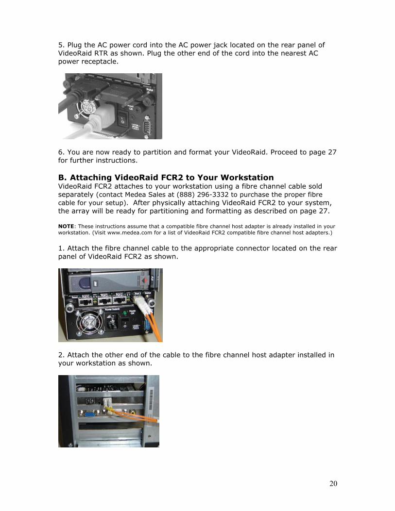
1. Attach the fibre channel cable to the appropriate connector located on the rear panel of VideoRaid FCR2 as shown.
2. Attach the other end of the cable to the fibre channel host adapter installed in your workstation as shown.

21
3. Plug the AC power cord into the AC power jack located on the rear panel of VideoRaid FCR as shown below. Plug the other end of the cord into the nearest AC power receptacle.
4. You are now ready to partition and format your VideoRaid. Proceed to page 27 for further instructions. C. Attaching VideoRaid RTRX to Your Workstation VideoRaid RTRX Single Channel Configuration Follow the instructions below to attach the VideoRaid RTRX disk array to your workstation. After physically attaching VideoRaid RTRX to your system, the array will be ready for partitioning and formatting as described on page 27. NOTE: These instructions assume that a compatible Ultra320 host adapter is already installed in your workstation. (Visit www.medea.com for a list of VideoRaid RTRX compatible SCSI host adapters.)
1. Check the SCSI IDs on Your VideoRaid RTRX before proceeding. A fully populated VideoRaid RTRX with (10) drives has two SCSI ID selectors located on the back of the array. Channel A of VideoRaid RTRX is shipped from the factory with a default SCSI ID setting of ID 6. Channel B of VideoRaid RTRX is shipped from the factory with a default SCSI ID setting of ID 5. If your system does not include other SCSI peripherals, use the default setting. If you have other SCSI internal or external devices attached to your workstation, set the SCSI IDs on VideoRaid RTRX to settings that do not conflict with these devices. NOTE: Most SCSI HBAs ship with a utility that allows you to scan the SCSI bus to determine the SCSI ID of each peripheral. Use this utility to ensure that the SCSI ID you select for VideoRaid does not conflict with these other peripherals. There are sixteen (16) available SCSI ID settings, 0-15. Do not use ID 7, as this ID is reserved for the SCSI host adapter.
2. 5-Drive RTRX. If your VideoRaid RTRX is populated with five (5) disk drive modules, attach the supplied SCSI cable and terminator to the SCSI connectors on the back of the array as shown on the following page. Use the thumbscrews to secure the cable and terminator in place.
WARNING! Damage to the cable & controller will result if care is not taken to ensure proper mating in the correct orientation to the SCSI port on VideoRaid.

22
3. 10-Drive RTRX. If your VideoRaid RTRX is populated with ten (10) disk drive modules, attach the supplied SCSI cable and terminator to the SCSI connectors on the back of the array in a “daisy chained” configuration as shown below. Use the thumbscrews to secure the cables and terminator in place.
NOTE: If you are using a dual channel SCSI controller, you may hook up each channel of VideoRaid RTRX to each channel of the SCSI adapter as shown under “VideoRaid RTRX Dual Channel Configuration.”
WARNING! Damage to the cable & controller will result if care is not taken to ensure proper mating in the correct orientation to the SCSI port on VideoRaid. 4. Attach the free end of the SCSI cable to the external connector of your SCSI host adapter as shown. Use the thumbscrews to secure the cable in place.
WARNING! Damage to the cable & HBA will result if care is not taken to ensure proper mating in the correct orientation to the SCSI port on VideoRaid. 5. Plug the two (2) AC power cords into the two (2) AC power jacks located on the rear panel of VideoRaid RTRX as shown below. Plug the other end of the cords into the nearest AC power receptacle.

23
6. You are now ready to partition and format your VideoRaid. Proceed to page 27 for further instructions. D. VideoRaid RTRX Dual-Channel Striped Configuration Follow the instructions below to attach the VideoRaid RTRX disk array to your workstation as a dual-channel striped storage solution. After physically attaching VideoRaid RTRX to your system, the array will be ready for initializing as described on page 27. NOTE: These instructions assume a compatible dual-channel Ultra320 host adapter is already installed in your workstation. (Visit www.medea.com for a list of VideoRaid RTRX compatible SCSI host adapters.)
1. Attach the supplied SCSI cables and terminators to the connectors on the back of VideoRaid RTRX as shown. Use the thumbscrews to secure the cables and terminators in place.
WARNING! Damage to the cables & controller will result if care is not taken to ensure proper mating in the correct orientation to the SCSI port on VideoRaid. 2. Attach the free ends of the SCSI cables to the external connectors on your Ultra320 SCSI host adapter as shown below. Use the thumbscrews to secure the cables in place.
WARNING! Damage to the cable & HBA will result if care is not taken to ensure proper mating in the correct orientation to the SCSI port on VideoRaid. 3. Attach the supplied power cords to VideoRaid RTRX as shown below. Plug the cables into the nearest AC power receptacle.

24
4. You are now ready to format and partition your VideoRaid. Proceed to page 27 for further instructions. E. VideoRaid FCR2X Single-Channel Configuration Follow the instructions below to attach the VideoRaid FCR2X disk array to your workstation. After physically attaching VideoRaid FCR2X to your system, the array will be ready for initializing as described on page 27. NOTE: These instructions assume a compatible fibre channel host adapter is already installed in your workstation. (Visit the Medea web site at www.medea.com for a list of VideoRaid FCR2X compatible fibre channel host adapters.)
1. 5-Drive FCR2X. If your VideoRaid FCR2X is populated with five (5) disk drive modules, attach the fibre channel cable to the appropriate connector on the back of the array as shown.

25
2. 10-Drive FCR2X. If your VideoRaid FCR2X is populated with ten (10) disk drive modules, connect the host cable to one connector, and the other cable will attach the two halves of the array together in a daisy chain configuration.
NOTE: If you are using a dual channel fibre channel host adapter, you can hook up each channel of VideoRaid FCR2X to each channel on the host adapter as shown under “VideoRaid FCR2X Dual Channel Striped Configuration.”
3. Attach the other end of the fibre channel cable(s) to the external connector(s) of your fibre channel host adapter.
4. Plug the AC power cord(s) into the AC power jack(s) located on the rear panel of VideoRaid FCR2X as shown below. Plug the other end of the cords into the nearest AC power receptacle.
5. You are now ready to partition and format your VideoRaid. Proceed to page 27 for further instructions.

26
F. VideoRaid FCR2X Dual-Channel Striped Configuration Follow the instructions on the following page to attach the VideoRaid FCR2X disk array to your workstation as a dual-channel striped storage solution. After physically attaching VideoRaid FCR2X to your system, the array will be ready for initializing as described on page 27. NOTE: These instructions assume that a compatible dual-channel fibre channel host adapter is already installed in your workstation. (Visit the Medea web site at www.medea.com for a list of VideoRaid FCR2X compatible fibre channel host adapters.)
1. Attach a fibre channel cable to the connectors on the back of VideoRaid FCR2X as shown below.
2. Attach the free ends of the fibre channel cables to the external connectors on your fibre channel host adapter as shown below.
3. Attach the supplied power cords to VideoRaid FCR2X as shown below. Plug the cables into the nearest AC power receptacles.
4. You are now ready to partition and format your VideoRaid. Proceed to page 27 for further instructions.

27
IX. INITIALIZING VideoRaid Now that VideoRaid is physically connected to your workstation, the array must be initialized for use with your operating system. This includes striping (dual channel arrays, optional), formatting and partitioning (optional). A. Configuring VideoRaid for Formatting 1. Before configuring VideoRaid, check the Medéa web site at www.medea.com and select Support to ensure your unit has the latest firmware for your application. If you need to download firmware, please see Downloading Firmware for VideoRaid on page 47 (for PC) and 48 (for Mac). 2. All VideoRaid controllers are shipped configured to factory default settings. Most applications work with this configuration. However, to see if your application requires something other than the default, please visit our web site at www.medea.com under “Support.” Click on “Compatibility” to find information on the configuration required for your application. 3. Configuring VideoRaid requires the use of the Null Modem Cable that is included with VideoRaid. Use the following procedure corresponding to your OS to view the configuration parameters:
Warning! DO NOT configure an array that has data that you want to save without first consulting Medéa Technical Support.
a. Windows 2000/Server 2003/XP/XP Pro i. Attach one end of the Null Model Cable to the serial port on the power supply of the VideoRaid to be configured, and the other end to the serial port on your PC. ii. Start Hyper Terminal, select Com 1, and set the following parameters: Bits per second 57,600 Data Bits 8 Parity None Stop Bits 1 Flow Control None iii. Click OK, and then hit Esc to see the Main Menu. Select “Configure Array” and enter the settings for your application from the Medéa web site. b. Mac OS X i. Connect a USB to Serial Port Converter (not supplied) to a USB port on the Mac. Attach one end of the Null Modem Cable to the converter and the other end to the serial port on the power supply of the VideoRaid to be configured. ii. If you do not have a copy of “ZTerm,” a terminal emulation program for the Mac, you can download it free using the following link: http://www.download.com/ZTerm/3000-2274_4-5656715.html iii. Launch ZTerm and set up the communication settings from the dropdown menu for the Serial Port Converter. iv. Go to the Settings pull-down menu and select Connection. In this window ensure the following settings:
Data Rate 57,600 Data Bits 8 Parity None Stop Bits 1 Flow Control Both boxes Unchecked

28
v. Click OK, highlight the terminal window and then hit any key to see the main menu. Select “Configure Array” and enter the settings for your application from the Medéa web site. c. SGI IRIX i. Use a PC to configure and follow instructions for Windows 2000/Server 2003/XP/XP Pro in item “a.” above. B. Formatting VideoRaid
Single Channel SCSI for Fibre Channel Configurations If you set up your VideoRaid in a single-channel configuration, refer to the sections below for instructions on initializing the array. • For Windows 2000/XP/XP Pro, proceed to the item “C.” below. • For Mac OS X, proceed to page 34. • For IRIX (Fibre Channel Only) refer to your SGI documentation. VideoRaid FCR2 will appear as a single LUN to the host.
Dual Channel SCSI or Fibre Channel Configurations If you set up your VideoRaid in a dual-channel configuration and wish to stripe across these channels, refer to the sections below for instructions. • Striping under Windows 2000/XP Pro, proceed to page 37. • Striping under Mac OS X, proceed to page 44. • For IRIX (Fibre Channel Only) refer to your SGI documentation. VideoRaid FCR2 will appear as two (2) LUNs to the host.
NOTE: Avid systems ship with a “striping” utility called “AVIDdrive”. Follow the instructions that came with this utility to stripe across VideoRaid’s channels. Remember to disable the “drive filtering” option located in the “General” settings menu.
C. Single Channel Configuration – Windows 2000/XP/XP Pro NOTE: This procedure will create a Basic Disk volume on VideoRaid. Initializing VideoRaid as a Basic Disk will enable you to use the array on any workstation running Windows 2000/XP/XP Pro. VideoRaid may also be initialized as a Dynamic Disk. Please refer your Windows documentation for more information.
1. Power on the VideoRaid disk array, wait 20 seconds, then power on your Windows workstation. 2. To open Disk Management, right-click on My Computer and select Manage in the drop down window as shown in the window below:

29
3. The Computer Management console will appear. Click on Disk Management in the left-hand panel as shown below. VideoRaid is identified as Disk 1 in this example.
4. Right-click on the Disk 1 entry as shown and select New Partition from the pull-down menu.
5. The following window will appear. Click on Next to continue.

30
6. The following window will appear. Click on Next to continue.
7. The following window will appear. Click on Next to continue.
This will create one large volume (one drive letter) using all of the available space on the VideoRaid. NOTE: Multiple partitions can be created on VideoRaid. Consult your Windows documentation for instructions to set up multiple partitions.

31
8. The following window will appear. Windows will automatically assign a drive letter (In this example–E:) to VideoRaid. Accept this assignment and click the Next button to continue.
9. The window below will appear. Enter a Volume Label: (in this example–VideoRaid), check the Perform a quick format box and click the Next button to continue. For better performance, use 64K allocation size instead of default.

32
10. The following window will appear. Click the Finish button to continue.
11. Windows will format the volume and then display the following window. Disk 1 is now identified as VideoRaid (E:).

33
12. VideoRaid will now be displayed as an available hard disk drive under My Computer as shown below.
Congratulations! You are now ready to edit with VideoRaid!

34
D. SINGLE-CHANNEL CONFIGURATION – MAC OS X To initialize VideoRaid under Mac OS X, follow the instructions below. 1. Power on your VideoRaid disk array, wait 20 seconds, then power on your Mac OS X workstation. An Alert window will appear as shown below. This is normal.
NOTE: If the Alert window does not appear, launch the Apple Disk Utility located in the Utilities folder on the Macintosh HD.
2. Select Initialize... to open the Apple Disk Utility. A window like the following will appear. VideoRaid will be displayed in the left-hand column as shown.
3. Select VideoRaid by clicking on the entry in the left-hand column as shown below. Information on the array will be displayed on the right.

35
4. Select the Partition tab to view the partition options as shown on the next page.
5. Set the Volume Scheme: to Current. Enter a Volume Name: under Volume Information (in this example–VideoRaid), set format to Mac OS Extended, and if you intend to use the module on a Mac running OS 9, check the box under Options.
NOTE: VideoRaid can be set up in multiple volumes if desired. Please refer to the Apple documentation for instructions.
6. Click on the Partition button. The following Warning! window will appear. Click on the Partition button to continue.

36
7. When partitioning is complete, VideoRaid will be displayed in the left-hand window as shown below.
8. Exit the Disk Utility. 9. VideoRaid will be displayed on the desktop as shown below.
Congratulations! You are now ready to edit with VideoRaid!

37
E. STRIPING VIDEORAID CHANNELS – Windows 2000/Server 2003/LP/XP Pro If you purchased two VideoRaid RTR arrays or a 10-drive VideoRaid RTRX and wish to stripe (using a dual-channel SCSI host adapter) for increased performance, follow the directions below. 1. Power on your VideoRaid disk array, wait 20 seconds, then power on your workstation. 2. Right-click on the My Computer icon located on the desktop and select Manage from the pull-down menu as shown below.
3. The Computer Management console will appear. Click on Disk Management in the left-hand panel as shown below. The VideoRaid disk arrays are identified as Disk 1 and Disk 2 in this example.
4. If 2 disks are not seen here, you may need to use the RS-232 port to configure the Fibre Channel ALPAs (Arbitrated Loop Port Addresses) to be different values. This is highly unusual, but in the unlikely event you have related issues, please contact Medéa Technical Support.

38
5. Right-click on the box labeled Disk 1 and select Convert to Dynamic Disk... from the pull-down menu as shown.
6. The following window will appear. Select Disk 1 and Disk 2 by checking each box and click the OK button to continue.
WARNING: Be absolutely sure that the disks you check in this step represent the VideoRaid disk arrays before proceeding. Selecting other disk drives will cause loss of data on those drives.
7. The following window will appear. Note Disk 1 & 2 are identified as Dynamic.

39
8. Right-click on the Disk 1 entry and select Create Volume, as shown below.
9. The New Volume Wizard will appear. Click the Next button to continue.
10. The following window will appear. Select Striped by clicking on the radio button and click the Next button to continue.

40
11. The following window will appear. Select Disk 2 in the left-hand panel as shown and click on the Add button.
12. Disk 2 will now be displayed in the Selected: panel as shown below. Click on the Next button to continue. This will create a stripe set consisting of one large volume (one drive letter) utilizing all of the available space on both VideoRaids.
NOTE: Multiple striped partitions can be created. Refer to your Windows documentation for more information.

41
13. The following window will appear. Windows will automatically assign a drive letter (in this example–F:) to the VideoRaid stripe set. Accept this assignment and click on the Next button to continue.
14. The following window will appear. Enter a Volume Label: (In this example–VideoRaid), check the Perform a quick format box and click on the Next button to continue.

42
15. The following window will appear. Click on the Finish button to continue.
16. Windows will format the stripe set and then display the following window. Disk 1 and Disk 2 are now identified as a striped set called VideoRaid. Close the Computer Management window.

43
17. The VideoRaid stripe set is now displayed as a useable volume under My Computer.
Congratulations! You are now ready to edit with VideoRaid!

44
F. STRIPING VIDEORAID CHANNELS – Mac OS X If you purchased two VideoRaid RTR arrays or a 10-drive VideoRaid RTRX and wish to stripe (using a dual-channel SCSI host adapter) for increased performance, follow the directions below. 1. Power your VideoRaid disk array, wait 20 seconds, then power on your Macintosh. An Alert window will appear as shown. This is normal.
NOTE: If the Alert window does not appear, launch the Apple Disk Utility located in the Utilities folder on the Macintosh HD. 2. Select Initialize... to open the Apple Disk Utility. A window like the following will appear. The VideoRaid disk arrays will be displayed in the left-hand column as shown.

45
3. Select a VideoRaid by clicking on the entry in the left-hand column as shown below. Information on the array will be displayed on the right.
4. Click the RAID tab to view the RAID options as shown below.

46
5. Drag each VideoRaid entry from the left-hand column to the right area labeled Drag disks here to add to set. Set RAID Scheme: to Stripe, enter a RAID Set Name: (in this example–VideoRaid Stripe) and set the Volume Format: to Mac OS Extended as shown below.
6. Click the Create button. The following Warning! will appear. Click on the Create button to continue.
7. When complete, the VideoRaid stripe set will be displayed in the left-hand window as shown below.

47
8. Exit the Disk Utility. 9. The VideoRaid stripe set will be displayed as an icon on the desktop. Congratulations! You are now ready to edit with VideoRaid! G. Downloading VideoRaid Firmware on your PC Note: Although downloading firmware is not a destructive process, it is always best to backup your critical data before downloading new firmware.
1. The firmware version loaded into your VideoRaid (i.e.: “vf2p_02_35x21” for fibre channel, or “vrtp_01_61xd14” for SCSI) can be found on the title page that appears when using Hyper Terminal. (See page 27 for instructions.) 2. Check the Medéa web site under “Support” for the most recent firmware version for your SCSI or Fibre Channel VideoRaid. 3. If your firmware version is a lower number than what is on the Medea web site, you may want to download the newer version following these instructions: a. Ensure your system is started with VideoRaid connected, and no applications are running. Note: It is strongly suggested that you install the most current driver for your host bus adapter before proceeding with the Medéa firmware download procedure.
b. Download the new firmware revision off the Medéa web site to your desktop. c. Double click the downloaded file to unzip and save it to your system. The default location is C:Medea. d. In the Medéa folder, double click on “vr_install_1v1.exe”. e. In the resulting window, click “Install”. The firmware will be sent over the SCSI or Fibre Channel port to the array. Note: DO NOT power down the array or the system, or attempt to stop the download process once it has begun!
f. When the installation is complete, new icons appear in the Medéa folder. Double click “VRUtil” and a window will open. Note: If a message “Unable to load winaspi32.dll” appears, go to www.adaptec.com, search on “winaspi” and download the appropriate file for your OS.
g. Click on the “Options” tab and put a check in the box next to the unit to be updated. Click on the folder icon in the upper left (below the File Menu) and this will open another window. Navigate to the firmware you want to install, highlight and click “Open.” h. Click “Download” in the lower right and the firmware will begin downloading to the array. i. When the download completes, power off the PC, power cycle the array(s), and power on the PC. If for any reason the process does not appear to complete, or the system has problems rebooting, contact Technical Support.

48
H. Downloading VideoRaid Firmware on your Mac Note: Although downloading firmware is not a destructive process, it is always best to backup your critical data before downloading new firmware.
1. The firmware version loaded into your VideoRaid (i.e.: “vf2p_02_35x21” for fibre channel, or “vrtp_01_61xd14” for SCSI) can be found on the title page that appears when using ZTerm, (See page 27 for instructions) or by using the System Profiler. 2. Check the Medéa web site under “Support” for the most recent firmware version for your SCSI or Fibre Channel VideoRaid. 3. If your firmware version is a lower number than what is on the Medea web site, you may want to download the newer version using the following instructions: a. Ensure your system is started with VideoRaid connected and no applications are running. Note: It is strongly suggested that you install the most current driver for your host bus adapter before proceeding with the Medéa firmware download procedure.
b. Download the new firmware revision off the Medéa web site to your desktop. C. The Mac OS will automatically extract the files into a folder named “OSX-RTR-1nnxn” for VideoRaid RTR/RTRX, and “OSX-Utility-FCR2-2nnxn” for VideoRaid FCR2/FCR2X. d. Open the folder, double click on MedeaDriver.pkg and follow the on-screen installation instructions. This will load the Medéa extension. Upon completion, restart your Mac. e. If they are mounted, unmount the VideoRaid volume(s). f. Double click on the application “VideoRaid Config Utility”. g. Select the array(s) to be updated and click the “Update F/W” button. This starts the download of firmware to the array(s) through the SCSI or Fibre Channel port. Note: DO NOT power down the array or the system, or attempt to stop the download process once it has begun!
h. When the download completes, power off the Mac, power cycle the array(s), and power on the Mac. If for any reason the process does not appear to complete, or the system has problems rebooting, contact Technical Support.

49
X. TECHNICAL SUPPORT If you encounter any difficulties while installing your VideoRaid disk array, please contact Medéa Technical Support via one of the following ways: Telephone: (818) 880-0303 Fax: (818) 880-6906 E-mail: [email protected] Internet: www.medea.com Thank you for purchasing a VideoRaid disk array. If you have any comments or questions about this manual or the product, please call (818) 880-0303, or send an email to [email protected].
XI. 3-YEAR LIMITED WARRANTY Medéa Corporation (Medéa) warrants to the purchaser of this product that it will be free from defects in material and workmanship for a period of three (3) years from the date of purchase. If the product should become defective within the warranty period, Medéa, at its option, will repair or replace the product, or refund the purchaser’s price for the product, provided it is delivered at the purchaser’s expense to an authorized Medéa service facility or to Medéa. Repair or replacement parts or products will be furnished on an exchange basis and will be either new or reconditioned. All replaced parts or products shall become the property of Medéa. This warranty shall not apply if the product has been damaged by accident, misuse, abuse or as a result of unauthorized service or parts. Warranty service is available to the purchaser by obtaining a Return Material Authorization number (RMA) and by delivering the product during the warranty period to an authorized Medéa service facility or to Medéa. The purchaser shall bear all shipping, packing and insurance costs and all other costs, excluding parts and labor, necessary to effectuate repair, replacement or refund under this warranty. All returned product must be shipped to Medéa in the original shipping container. For more information on how to obtain warranty service, an RMA number or to acquire shipping materials, contact Medéa at 5525 Oakdale Avenue, Suite 240 Woodland Hills, CA 91364 (818) 880-0303. THIS LIMITED WARRANTY DOES NOT EXTEND TO ANY PRODUCT WHICH HAS BEEN DAMAGED AS A RESULT OF ACCIDENT, MISUSE, ABUSE, OR AS A RESULT OF UNAUTHORIZED SERVICE OR PARTS. THIS WARRANTY IS IN LIEU OF ALL OTHER EXPRESS WARRANTIES WHICH NOW OR HEREAFTER MIGHT OTHERWISE ARISE WITH RESPECT TO THIS PRODUCT. IMPLIED WARRANTIES, INCLUDING THOSE OF MERCHANTABILITY, FITNESS FOR A PARTICULAR PURPOSE, AND NON-INFRINGEMENT SHALL (A) HAVE NO GREATER DURATION THAN 2 YEARS FROM THE DATE OF PURCHASE, (B) TERMINATE AUTOMATICALLY AT THE EXPIRATION OF SUCH PERIOD AND (C) TO THE EXTENT PERMITTED BY LAW BE EXCLUDED. IN THE EVENT THIS PRODUCT BECOMES DEFECTIVE DURING THE WARRANTY PERIOD, THE PURCHASER’S EXCLUSIVE REMEDY SHALL BE REPAIR, REPLACEMENT, OR REFUND AS PROVIDED ABOVE. INCIDENTAL OR CONSEQUENTAL DAMAGES, INCLUDING WITHOUT LIMITATION LOSS OF DATA, ARISING FROM BREACH OF ANY EXPRESS OR IMPLIED WARRANTY ARE NOT THE RESPONSIBILITY OF MEDÉA AND, TO THE EXTENT PERMITTED BY LAW, ARE HEREBY EXCLUDED BOTH FOR PROPERTY DAMAGE, AND TO THE EXTENT NOT UNCONSCIONABLE, FOR PERSONAL INJURY DAMAGE. Some states do not allow the exclusion or limitation of incidental or consequential damages for consumer products, and some states do not allow limitations on how long an implied warranty lasts, so the above limitations or exclusions may not apply to you. This warranty gives you specific legal rights, and you may also have other rights which vary from state to state or country.