
Video Target Practice - MITweb.mit.edu/6.111/www/s2004/PROJECTS/12/report12.pdf · 2.0 The Nintendo...
52
Video Target Practice Faye Kasemset Andrew Klock Dave Kloster MIT 6.111 - Introductory Digital Systems Laboratory Prof. Anantha Chandrakasan TA: David Milliner May13, 2004
Transcript of Video Target Practice - MITweb.mit.edu/6.111/www/s2004/PROJECTS/12/report12.pdf · 2.0 The Nintendo...
Video Target Practice
Faye Kasemset Andrew Klock Dave Kloster
MIT 6.111 - Introductory Digital Systems LaboratoryProf. Anantha Chandrakasan
TA: David Milliner
May13, 2004
Table of Contents
1.0 Overview Page 1
2.0 The Nintendo Zapper Interface Page 2
3.0 Targeting Page 3
4.0 Video Controller Page 5
4.1 Hardware Description Page 5
4.2 Module Design Descriptions Page 6
5.0 The Game Controller Page 8
5.1 Sample Timer Page 9
5.2 Random Number Generator Page 9
5.3 Address Selector Page 10
5.4 Control FSM Page 10
5.5 Add FSM Page 11
5.6 Move FSM Page 12
6.0 Audio Extension Page 13
7.0 Design and Debugging Issues Page 14
8.0 Conclusions Page 16
Kasemset :: Klock :: Kloster i
List of Figures
Figure 1. Overall System Layout and Design Page 1
Figure 2. Internal Nintendo Zapper Page 2
Figure 3. Internal and Interface Schematic Design Page 2
Figure 4. Zapper Signals Page 3
Figure 5. Processed Gun Signals Page 3
Figure 6. Targeting Mode Controller Inputs and Drawing Page 4
Figure 7. Real-Time Targeting Analysis Page 4
Figure 8. Video Circuits Page 6
Figure 9. Video Module Block Diagram Page 6
Figure 10. Major and Minor FSMs Page 7
Figure 11. Draw FSMs Write Cycle Timing Diagram Page 8
Figure 12. Game Controller Block Diagram Page 9
Figure 13. LFSR of Arbitrary Bit Length Page 10
Figure 14. Control FSM Transition Diagram Page 11
Figure 15. Add FSM Transition Diagram Page 12
Figure 16. Move FSM Transition Diagram Page 13
Figure 17. Target Movement Page 13
Figure 18. Audio Interface Extension Page 14
Figure 19. Audio Controller Timing Diagram Page 14
Kasemset :: Klock :: Kloster ii
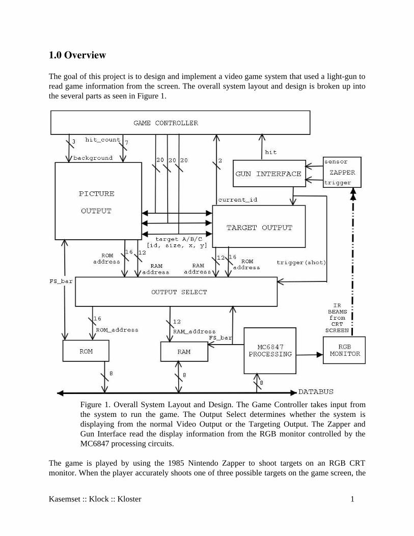
1.0 Overview
The goal of this project is to design and implement a video game system that used a light-gun toread game information from the screen. The overall system layout and design is broken up intothe several parts as seen in Figure 1.
Figure 1. Overall System Layout and Design. The Game Controller takes input fromthe system to run the game. The Output Select determines whether the system isdisplaying from the normal Video Output or the Targeting Output. The Zapper andGun Interface read the display information from the RGB monitor controlled by theMC6847 processing circuits.
The game is played by using the 1985 Nintendo Zapper to shoot targets on an RGB CRTmonitor. When the player accurately shoots one of three possible targets on the game screen, the
Kasemset :: Klock :: Kloster 1
target that has been hit is removed, and the game score is incremented by one. The targets followand arching pathway across the game screen and progressively get smaller to give the illusionthat they are flying away from the player. There are four levels with forty-four possible targets.
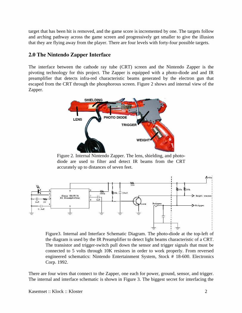
2.0 The Nintendo Zapper Interface
The interface between the cathode ray tube (CRT) screen and the Nintendo Zapper is thepivoting technology for this project. The Zapper is equipped with a photo-diode and and IRpreamplifier that detects infra-red characteristic beams generated by the electron gun thatescaped from the CRT through the phosphorous screen. Figure 2 shows and internal view of theZapper.
Figure 2. Internal Nintendo Zapper. The lens, shielding, and photo-diode are used to filter and detect IR beams from the CRTaccurately up to distances of seven feet.
Figure3. Internal and Interface Schematic Diagram. The photo-diode at the top-left ofthe diagram is used by the IR Preamplifier to detect light beams characteristic of a CRT.The transistor and trigger-switch pull down the sensor and trigger signals that must beconnected to 5 volts through 10K resistors in order to work properly. From reversedengineered schematics: Nintendo Entertainment System, Stock # 18-600. ElectronicsCorp. 1992.
There are four wires that connect to the Zapper, one each for power, ground, sensor, and trigger.The internal and interface schematic is shown in Figure 3. The biggest secret for interfacing the
Kasemset :: Klock :: Kloster 2
hardware is that the sensor and trigger signals coming from the Zapper are not self-generating.To interface to the Zapper, two 10K pull-up resistors must connect the sensor and trigger signalsto the 5 volt power supply. The Zapper pulls the voltage down using a transistor for the sensorand a push-switch for the trigger.
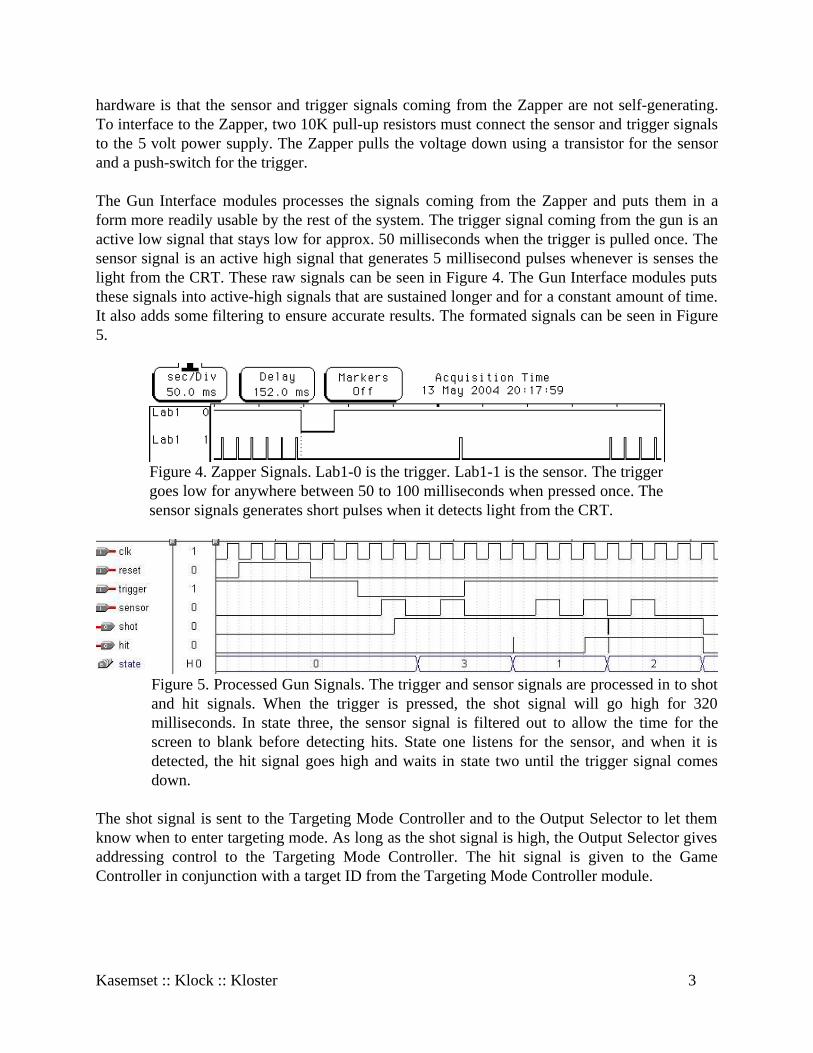
The Gun Interface modules processes the signals coming from the Zapper and puts them in aform more readily usable by the rest of the system. The trigger signal coming from the gun is anactive low signal that stays low for approx. 50 milliseconds when the trigger is pulled once. Thesensor signal is an active high signal that generates 5 millisecond pulses whenever is senses thelight from the CRT. These raw signals can be seen in Figure 4. The Gun Interface modules putsthese signals into active-high signals that are sustained longer and for a constant amount of time.It also adds some filtering to ensure accurate results. The formated signals can be seen in Figure5.
Figure 4. Zapper Signals. Lab1-0 is the trigger. Lab1-1 is the sensor. The triggergoes low for anywhere between 50 to 100 milliseconds when pressed once. Thesensor signals generates short pulses when it detects light from the CRT.
Figure 5. Processed Gun Signals. The trigger and sensor signals are processed in to shotand hit signals. When the trigger is pressed, the shot signal will go high for 320milliseconds. In state three, the sensor signal is filtered out to allow the time for thescreen to blank before detecting hits. State one listens for the sensor, and when it isdetected, the hit signal goes high and waits in state two until the trigger signal comesdown.
The shot signal is sent to the Targeting Mode Controller and to the Output Selector to let themknow when to enter targeting mode. As long as the shot signal is high, the Output Selector givesaddressing control to the Targeting Mode Controller. The hit signal is given to the GameController in conjunction with a target ID from the Targeting Mode Controller module.
Kasemset :: Klock :: Kloster 3
3.0 Targeting
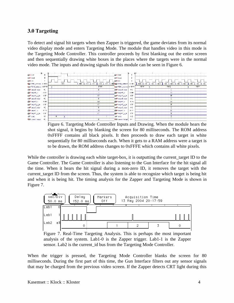
To detect and signal hit targets when then Zapper is triggered, the game deviates from its normalvideo display mode and enters Targeting Mode. The module that handles video in this mode isthe Targeting Mode Controller. This controller proceeds by first blanking out the entire screenand then sequentially drawing white boxes in the places where the targets were in the normalvideo mode. The inputs and drawing signals for this module can be seen in Figure 6.
Figure 6. Targeting Mode Controller Inputs and Drawing. When the module hears theshot signal, it begins by blanking the screen for 80 milliseconds. The ROM address0xFFFF contains all black pixels. It then proceeds to draw each target in whitesequentially for 80 milliseconds each. When it gets to a RAM address were a target isto be drawn, the ROM address changes to 0xFFFE which contains all white pixels.
While the controller is drawing each white target-box, it is outputting the current_target ID to theGame Controller. The Game Controller is also listening to the Gun Interface for the hit signal allthe time. When it hears the hit signal during a non-zero ID, it removes the target with thecurrent_target ID from the screen. Thus, the system is able to recognize which target is being hitand when it is being hit. The timing analysis for the Zapper and Targeting Mode is shown inFigure 7.
Figure 7. Real-Time Targeting Analysis. This is perhaps the most importantanalysis of the system. Lab1-0 is the Zapper trigger. Lab1-1 is the Zappersensor. Lab2 is the current_id bus from the Targeting Mode Controller.
When the trigger is pressed, the Targeting Mode Controller blanks the screen for 80milliseconds. During the first part of this time, the Gun Interface filters out any sensor signalsthat may be charged from the previous video screen. If the Zapper detects CRT light during this
Kasemset :: Klock :: Kloster 4
period, it must be pointed at a separate video source, and the system will not register a target forthis cycle. It is also important to note that the IR preamplifier in the gun only triggers the sensorsignal when it detects light characteristic of a CRT. It will not trigger the sensor signal if the gunis pointed at an ordinary light source.
After this period of blanking, the targeting controller sequentially displays white boxes for eachof the three possible targets. If and when the Zapper detects light from the CRT beginning in oneof these periods, the hit signal is sent to the Game Controller which then reads the current_targetID number, thereby registering a hit for that target.
4.0 Video Controller
For video, we use the MC6847 chip to output a 128x96 pixel, four-color image to the monitor.Target and background images are stored on a ROM. These images are then written to anSRAM based on directions from the game module. Writing to the SRAM is controlled by a setof major-minor FSMs, implemented in Verilog on a Flex10K70 FPGA (together with the gunand game modules).
4.1 Hardware Description
Hardware Components
The hardware components used in the video display circuit are:
3.579545 MHz Crystal OscillatorMonitorMC6847 Video Display GeneratorTwo 74LS04 Inverter Chips22v10 PAL Chip74LS123 ChipTwo 26LS32 ChipsAm28F512 ROMMCM6264 SRAMAssorted resistors, potentiometers, and capacitors
Hardware Circuits
In order to make the MC6847 compatible with the monitors in the lab (it was designedfor use with standard TVs), we needed to run its outputs through several circuits: one to producea clock signal, one to center the display, and one to convert the output of the MC6847 fromanalog signals into plain RGB signals.
Kasemset :: Klock :: Kloster 5
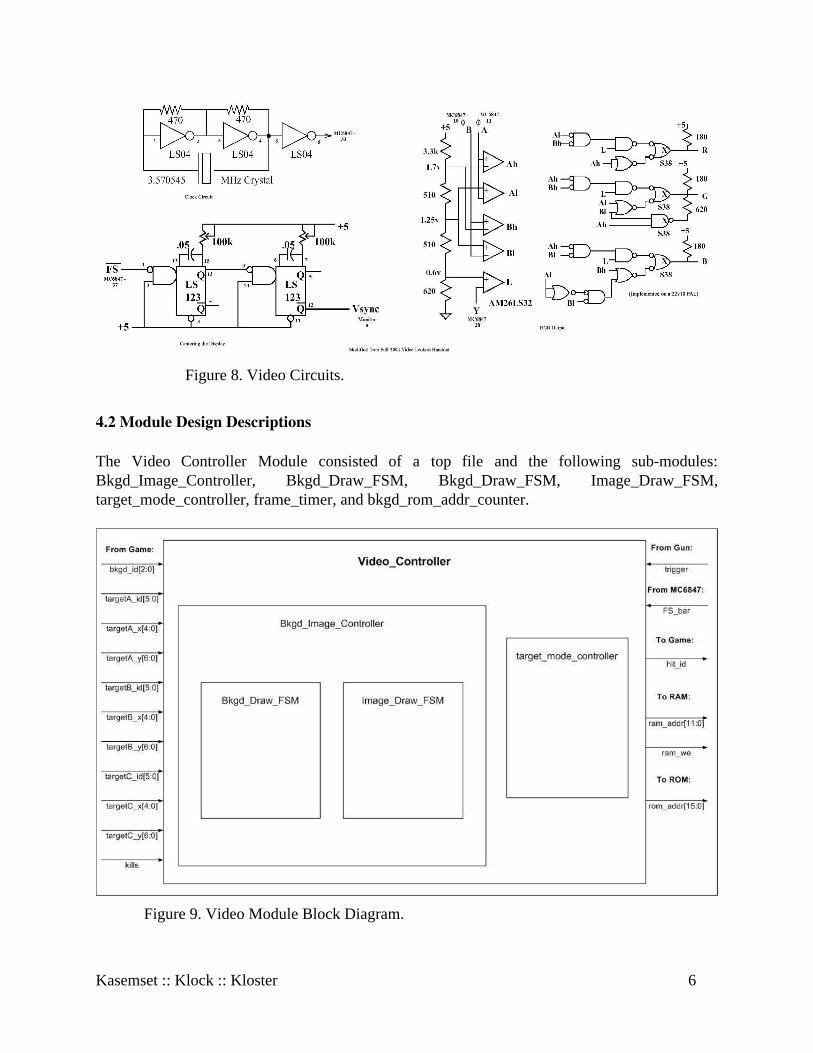
Figure 8. Video Circuits.
4.2 Module Design Descriptions
The Video Controller Module consisted of a top file and the following sub-modules:Bkgd_Image_Controller, Bkgd_Draw_FSM, Bkgd_Draw_FSM, Image_Draw_FSM,target_mode_controller, frame_timer, and bkgd_rom_addr_counter.
Figure 9. Video Module Block Diagram.
Kasemset :: Klock :: Kloster 6
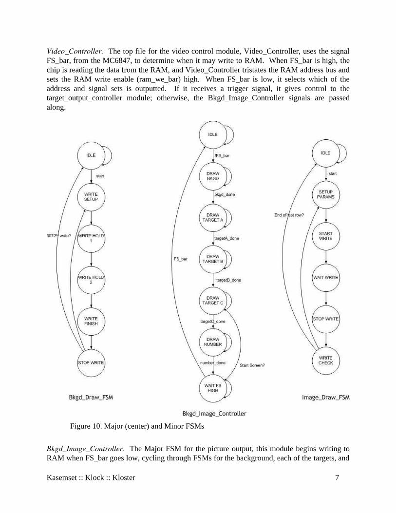
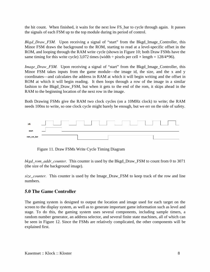
Video_Controller. The top file for the video control module, Video_Controller, uses the signalFS_bar, from the MC6847, to determine when it may write to RAM. When FS_bar is high, thechip is reading the data from the RAM, and Video_Controller tristates the RAM address bus andsets the RAM write enable (ram_we_bar) high. When FS_bar is low, it selects which of theaddress and signal sets is outputted. If it receives a trigger signal, it gives control to thetarget_output_controller module; otherwise, the Bkgd_Image_Controller signals are passedalong.
Figure 10. Major (center) and Minor FSMs
Bkgd_Image_Controller. The Major FSM for the picture output, this module begins writing toRAM when FS_bar goes low, cycling through FSMs for the background, each of the targets, and
Kasemset :: Klock :: Kloster 7
the hit count. When finished, it waits for the next low FS_bar to cycle through again. It passesthe signals of each FSM up to the top module during its period of control.
Bkgd_Draw_FSM. Upon receiving a signal of “start” from the Bkgd_Image_Controller, thisMinor FSM draws the background to the ROM, starting to read at a level-specific offset in theROM, and looping through the RAM write cycle (shown in Figure 10; both Draw FSMs have thesame timing for this write cycle) 3,072 times (width ÷ pixels per cell × length = 128/4*96).
Image_Draw_FSM. Upon receiving a signal of “start” from the Bkgd_Image_Controller, thisMinor FSM takes inputs from the game module—the image id, the size, and the x and ycoordinates—and calculates the address in RAM at which it will begin writing and the offset inROM at which it will begin reading. It then loops through a row of the image in a similarfashion to the Bkgd_Draw_FSM, but when it gets to the end of the rom, it skips ahead in theRAM to the beginning location of the next row in the image.
Both Drawing FSMs give the RAM two clock cycles (on a 10MHz clock) to write; the RAMneeds 100ns to write, so one clock cycle might barely be enough, but we err on the side of safety.
Figure 11. Draw FSMs Write Cycle Timing Diagram
bkgd_rom_addr_counter. This counter is used by the Bkgd_Draw_FSM to count from 0 to 3071(the size of the background image).
size_counter. This counter is used by the Image_Draw_FSM to keep track of the row and linenumbers.
5.0 The Game Controller
The gaming system is designed to output the location and image used for each target on thescreen to the display system, as well as to generate important game information such as level andstage. To do this, the gaming system uses several components, including sample timers, arandom number generator, an address selector, and several finite state machines, all of which canbe seen in Figure 12. Since the FSMs are relatively complicated, the other components will beexplained first.
Kasemset :: Klock :: Kloster 8
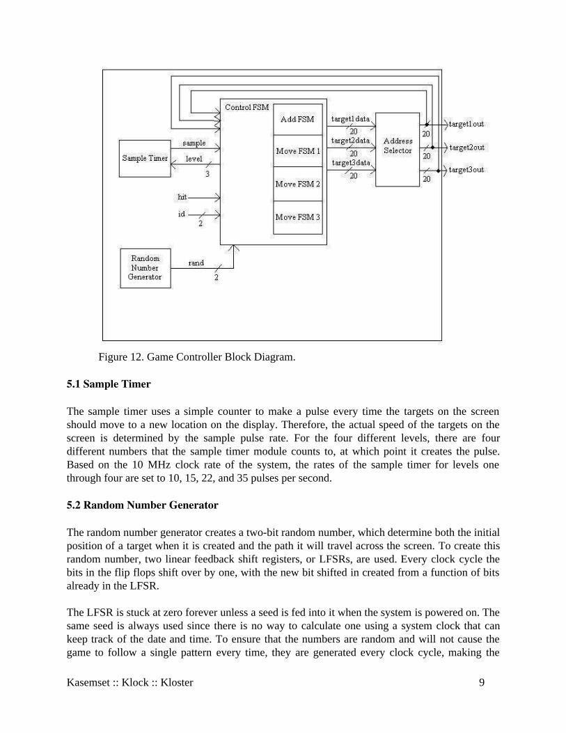
Figure 12. Game Controller Block Diagram.
5.1 Sample Timer
The sample timer uses a simple counter to make a pulse every time the targets on the screenshould move to a new location on the display. Therefore, the actual speed of the targets on thescreen is determined by the sample pulse rate. For the four different levels, there are fourdifferent numbers that the sample timer module counts to, at which point it creates the pulse.Based on the 10 MHz clock rate of the system, the rates of the sample timer for levels onethrough four are set to 10, 15, 22, and 35 pulses per second.
5.2 Random Number Generator
The random number generator creates a two-bit random number, which determine both the initialposition of a target when it is created and the path it will travel across the screen. To create thisrandom number, two linear feedback shift registers, or LFSRs, are used. Every clock cycle thebits in the flip flops shift over by one, with the new bit shifted in created from a function of bitsalready in the LFSR.
The LFSR is stuck at zero forever unless a seed is fed into it when the system is powered on. Thesame seed is always used since there is no way to calculate one using a system clock that cankeep track of the date and time. To ensure that the numbers are random and will not cause thegame to follow a single pattern every time, they are generated every clock cycle, making the
Kasemset :: Klock :: Kloster 9
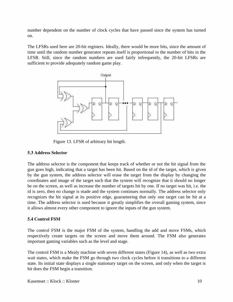
number dependent on the number of clock cycles that have passed since the system has turnedon.
The LFSRs used here are 20-bit registers. Ideally, there would be more bits, since the amount oftime until the random number generator repeats itself is proportional to the number of bits in theLFSR. Still, since the random numbers are used fairly infrequently, the 20-bit LFSRs aresufficient to provide adequately random game play.
Figure 13. LFSR of arbitrary bit length.
5.3 Address Selector
The address selector is the component that keeps track of whether or not the hit signal from thegun goes high, indicating that a target has been hit. Based on the id of the target, which is givenby the gun system, the address selector will erase the target from the display by changing thecoordinates and image of the target such that the system will recognize that it should no longerbe on the screen, as well as increase the number of targets hit by one. If no target was hit, i.e. theid is zero, then no change is made and the system continues normally. The address selector onlyrecognizes the hit signal at its positive edge, guaranteeing that only one target can be hit at atime. The address selector is used because it greatly simplifies the overall gaming system, sinceit allows almost every other component to ignore the inputs of the gun system.
5.4 Control FSM
The control FSM is the major FSM of the system, handling the add and move FSMs, whichrespectively create targets on the screen and move them around. The FSM also generatesimportant gaming variables such as the level and stage.
The control FSM is a Mealy machine with seven different states (Figure 14), as well as two extrawait states, which make the FSM go through two clock cycles before it transitions to a differentstate. Its initial state displays a single stationary target on the screen, and only when the target ishit does the FSM begin a transition.
Kasemset :: Klock :: Kloster 10
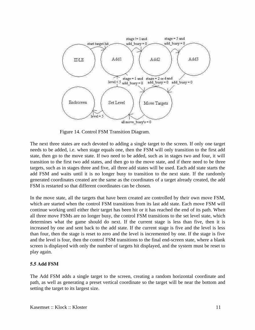
Figure 14. Control FSM Transition Diagram.
The next three states are each devoted to adding a single target to the screen. If only one targetneeds to be added, i.e. when stage equals one, then the FSM will only transition to the first addstate, then go to the move state. If two need to be added, such as in stages two and four, it willtransition to the first two add states, and then go to the move state, and if there need to be threetargets, such as in stages three and five, all three add states will be used. Each add state starts theadd FSM and waits until it is no longer busy to transition to the next state. If the randomlygenerated coordinates created are the same as the coordinates of a target already created, the addFSM is restarted so that different coordinates can be chosen.
In the move state, all the targets that have been created are controlled by their own move FSM,which are started when the control FSM transitions from its last add state. Each move FSM willcontinue working until either their target has been hit or it has reached the end of its path. Whenall three move FSMs are no longer busy, the control FSM transitions to the set level state, whichdetermines what the game should do next. If the current stage is less than five, then it isincreased by one and sent back to the add state. If the current stage is five and the level is lessthan four, then the stage is reset to zero and the level is incremented by one. If the stage is fiveand the level is four, then the control FSM transitions to the final end-screen state, where a blankscreen is displayed with only the number of targets hit displayed, and the system must be reset toplay again.
5.5 Add FSM
The Add FSM adds a single target to the screen, creating a random horizontal coordinate andpath, as well as generating a preset vertical coordinate so the target will be near the bottom andsetting the target to its largest size.
Kasemset :: Klock :: Kloster 11
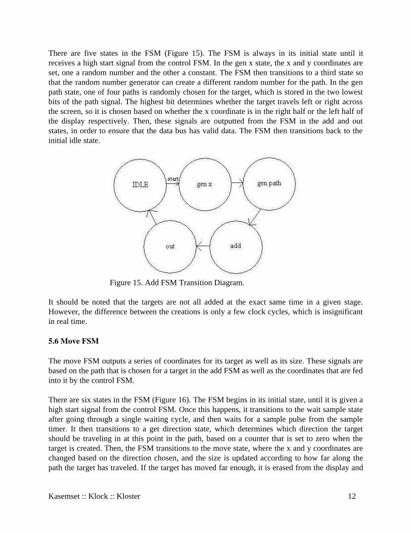
There are five states in the FSM (Figure 15). The FSM is always in its initial state until itreceives a high start signal from the control FSM. In the gen x state, the x and y coordinates areset, one a random number and the other a constant. The FSM then transitions to a third state sothat the random number generator can create a different random number for the path. In the genpath state, one of four paths is randomly chosen for the target, which is stored in the two lowestbits of the path signal. The highest bit determines whether the target travels left or right acrossthe screen, so it is chosen based on whether the x coordinate is in the right half or the left half ofthe display respectively. Then, these signals are outputted from the FSM in the add and outstates, in order to ensure that the data bus has valid data. The FSM then transitions back to theinitial idle state.
Figure 15. Add FSM Transition Diagram.
It should be noted that the targets are not all added at the exact same time in a given stage.However, the difference between the creations is only a few clock cycles, which is insignificantin real time.
5.6 Move FSM
The move FSM outputs a series of coordinates for its target as well as its size. These signals arebased on the path that is chosen for a target in the add FSM as well as the coordinates that are fedinto it by the control FSM.
There are six states in the FSM (Figure 16). The FSM begins in its initial state, until it is given ahigh start signal from the control FSM. Once this happens, it transitions to the wait sample stateafter going through a single waiting cycle, and then waits for a sample pulse from the sampletimer. It then transitions to a get direction state, which determines which direction the targetshould be traveling in at this point in the path, based on a counter that is set to zero when thetarget is created. Then, the FSM transitions to the move state, where the x and y coordinates arechanged based on the direction chosen, and the size is updated according to how far along thepath the target has traveled. If the target has moved far enough, it is erased from the display and
Kasemset :: Klock :: Kloster 12
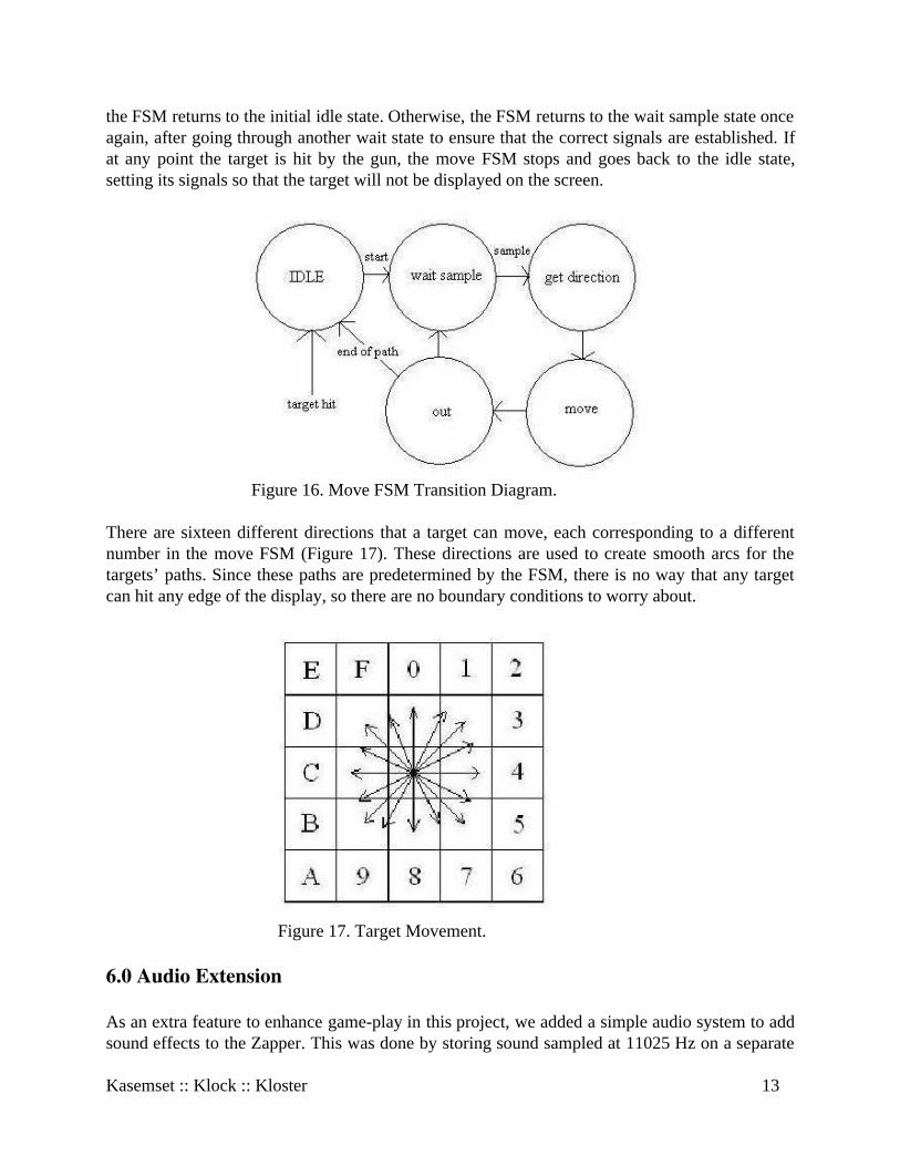
the FSM returns to the initial idle state. Otherwise, the FSM returns to the wait sample state onceagain, after going through another wait state to ensure that the correct signals are established. Ifat any point the target is hit by the gun, the move FSM stops and goes back to the idle state,setting its signals so that the target will not be displayed on the screen.
Figure 16. Move FSM Transition Diagram.
There are sixteen different directions that a target can move, each corresponding to a differentnumber in the move FSM (Figure 17). These directions are used to create smooth arcs for thetargets’ paths. Since these paths are predetermined by the FSM, there is no way that any targetcan hit any edge of the display, so there are no boundary conditions to worry about.
Figure 17. Target Movement.
6.0 Audio Extension
As an extra feature to enhance game-play in this project, we added a simple audio system to addsound effects to the Zapper. This was done by storing sound sampled at 11025 Hz on a separate
Kasemset :: Klock :: Kloster 13
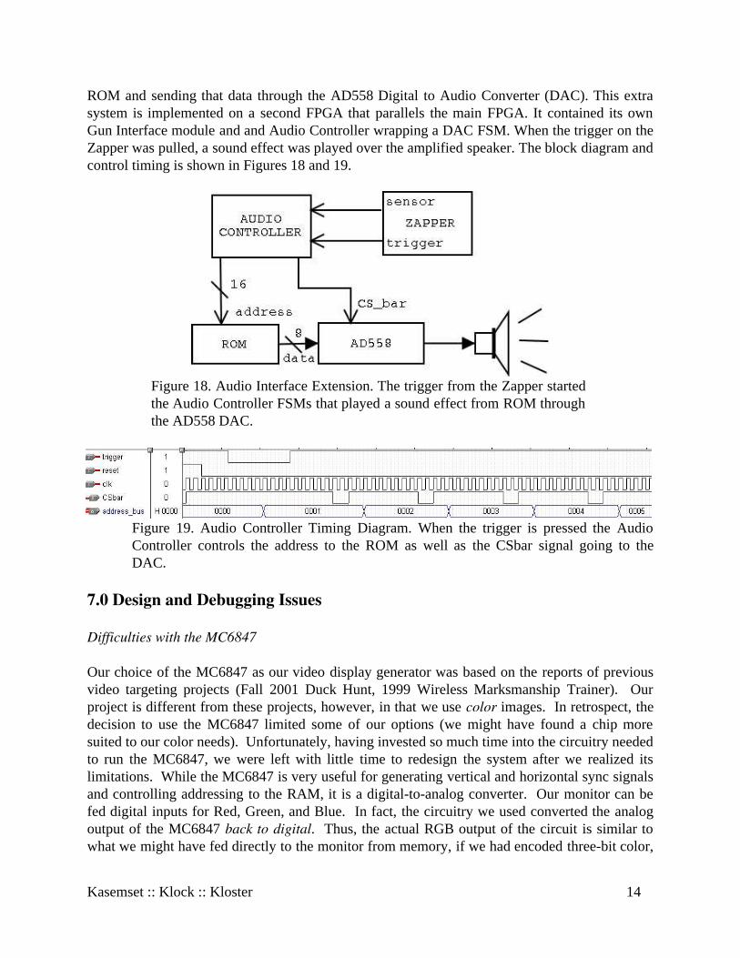
ROM and sending that data through the AD558 Digital to Audio Converter (DAC). This extrasystem is implemented on a second FPGA that parallels the main FPGA. It contained its ownGun Interface module and and Audio Controller wrapping a DAC FSM. When the trigger on theZapper was pulled, a sound effect was played over the amplified speaker. The block diagram andcontrol timing is shown in Figures 18 and 19.
Figure 18. Audio Interface Extension. The trigger from the Zapper startedthe Audio Controller FSMs that played a sound effect from ROM throughthe AD558 DAC.
Figure 19. Audio Controller Timing Diagram. When the trigger is pressed the AudioController controls the address to the ROM as well as the CSbar signal going to theDAC.
7.0 Design and Debugging Issues
Difficulties with the MC6847
Our choice of the MC6847 as our video display generator was based on the reports of previousvideo targeting projects (Fall 2001 Duck Hunt, 1999 Wireless Marksmanship Trainer). Ourproject is different from these projects, however, in that we use color images. In retrospect, thedecision to use the MC6847 limited some of our options (we might have found a chip moresuited to our color needs). Unfortunately, having invested so much time into the circuitry neededto run the MC6847, we were left with little time to redesign the system after we realized itslimitations. While the MC6847 is very useful for generating vertical and horizontal sync signalsand controlling addressing to the RAM, it is a digital-to-analog converter. Our monitor can befed digital inputs for Red, Green, and Blue. In fact, the circuitry we used converted the analogoutput of the MC6847 back to digital. Thus, the actual RGB output of the circuit is similar towhat we might have fed directly to the monitor from memory, if we had encoded three-bit color,
Kasemset :: Klock :: Kloster 14
minus four options (though this would have involved many tricky timing issues with the syncsignals, etc.). In our case, the mode we used only allowed us to select from four differentcolors—not a very attractive combination of colors, either. The mode we selected, ColorGraphics Three, purports to allow for eight colors, but this promise requires that the user switchbetween two modes using a control signal. The actual data read by the MC6847 in this modeconsists of 8-bit address locations on RAM, each representing a set of four pixels in a row.Thus, there was no space in which to encode the extra mode selector bit. Additionally, when wefinally got the MC6847 working with the monitor, we found that it only wrote to the middlesection of the screen, leaving a large border in one of two colors: green for one mode and white(called “buff” on the datasheet) in the other. For a project with a gun dependent upon white lightfor targeting information (both green and white register as “hits” with the gun), this situation wasless than ideal.
Having resigned ourselves (due to time constraints) to four-bit color, we resolved to at least havethe colors of our choice. By adding additional logic to the prescribed “RGB Output” circuit, weconverted the colors of the mode we were using (CG3, CSS=0) as follows: Green (00) to Black(to make the border of the screen black), Yellow (01) to Green, Blue (10) stayed Blue, and Red(11) to White. This gave us the palette for traditional clay shooting and a screen compatible withthe light gun.
Inter-kit signals and optimization
We began with the idea that the video, game, gun, and sound modules would be able to operateon separate kits. Initially, therefore, we were more concerned with accuracy than withefficiency. When we began to address system integration and interfaces, we realized that thegame and video modules had to be on the same kit: they had far more communication channelsthan there were physical nodes on the kits. We put both modules on the kit, and realized we hadanother problem; when we ran wires to and from the gun module on another kit, the interactionof the kits produced many glitches on the monitor output. It turned out that the trigger signalwas glitching badly in the transfer, in spite of several grounding wires between the kits. We thenmoved the gun module onto the same kit as the others. We got a basic version of our projectworking, and all was well.
Then, we decided to add the hit count to the screen. We began with the idea that we would addtwo digits, side by side. This involved adding a counter to the game and two instantiations of theImage_Draw_FSM to the Video module (as well as the images themselves, on the ROM). Itwould not fit. When we finally managed to fit it all on the Flex 10K70, we had turned theimages into two-digit numbers (to reduce the number of additional FSMs to one), cut severalidentification bits by up to half of their original length, reduced the size of counters, cut therandomization factor in the game (for starting locations) by a factor of 2^29, and optimized allthe FSMs (i.e., rather than having specified offsets for all the numbers, as we had been able to dofor the limited number of scattered images, we calculated all of them off of one initial offset).Having to fight for 800, then 300, then those last 20 logic cells forced us to look critically at theefficiency of our code and drastically reduce excessive and inefficient methods. Occasionally, it
Kasemset :: Klock :: Kloster 15

forced us to sacrifice nice features, like the extensive randomization, but we found that thedifference was not noticeable in practice.
8.0 Conclusions
Overall we feel we succeeded in most of the goals we set out to achieve. Had there been no timeconstraints we would have enjoyed implementing additional features such as wireless for thegun, extra sounds, a greater palette of colors, a more detailed game over screen, and morecomplicated game play. It would have helped to have had an FPGA that could hold morefeatures.
What our final project does include is: � Moving targets that appear at a random location and move away from the user on a
predetermined path, shrinking as they disappear into the distance.� Working gun interface that recognizes specific targets� Four color video output� Four five-stage levels, each with different backgrounds, targets, and speeds\� Running score count� Sound module to make realistic gun noise
Kasemset :: Klock :: Kloster 16
/* Adds targets to the screen by generating initial x and y values while choosing a path for the target to follow.*/module addfsm(clk, reset, start, rand, busy, x, y, path);
input clk, reset, start;input[1:0] rand;output busy;output[6:0] x, y;output[2:0] path;reg busy, busy_int;reg[6:0] x, y, x_int, y_int;reg[2:0] path, path_int, state, next;
parameter IDLE = 0;parameter gen_x = 1;parameter gen_path = 2;parameter add = 3;parameter out = 4;
parameter bottom = 57;parameter middle = 63;
always @ (posedge clk) beginif (reset) state <= IDLE;else state <= next;x <= x_int;y <= y_int;path <= path_int;busy <= busy_int;
end
always @ (start or reset or state or next or rand or busy or x or y or path)case(state)IDLE: if (start) begin
next = gen_x;busy_int = 1;y_int = bottom;endelse beginnext = IDLE;x_int = x;y_int = y;path_int = path;busy_int = 0;end
gen_x: beginnext = gen_path;busy_int = 1;x_int = (rand * 25) + 15;y_int = bottom;end
gen_path: beginbusy_int = 1;x_int = x;y_int = y;next = add;path_int[1:0] = rand[1:0];if (x > middle) path_int[2] = 1;else path_int[2] = 0;end
add: beginnext = out;busy_int = 1;x_int = x;y_int = y;path_int = path;end
out: beginnext = IDLE;busy_int = 0;x_int = x;y_int = y;path_int = path;end
default: beginnext = IDLE;busy_int = 0;x_int = 0;y_int = 0;path_int = 0;end
endcaseendmodule
/************************************* Filename: addr_counter.v Author: Dave Kloster Custom counter used to cycle through the address bus of the Video RAM. *************************************/
module addr_counter(clk, reset, count, address, full);
input clk, reset; input count;
output full; reg full; output [11:0] address; reg [11:0] address; always @ (posedge clk or posedge reset) begin if (reset) begin
address <= 0; full <= 0;
end else if (count) begin
address <= address + 1; if (address == 12'hC00) begin //if (address == 12'd50) begin //TESTING VALUE full <= 1; address <= 0; end else full <= 0;
end else address <= 0; end // always @ (posedge clk or posedge reset)endmodule // addr_counter
/* This module decides if a target has been hit, and if it has, then changes its input so it will be erased from the display, and then adds one to the kill count. Otherwise, no change is made to the input.*/module address_selector(clk, reset,
x1, y1, image1, size1, x2, y2, image2, size2, x3, y3, image3, size3, x1_f, y1_f, image1_f, size1_f, x2_f, y2_f, image2_f, size2_f, x3_f, y3_f, image3_f, size3_f, hit, id, level, kills);
input clk, reset, hit;input [1:0] id;input[2:0] image1, image2, image3, size1, size2, size3, level;input[6:0] x1, x2, x3, y1, y2, y3;output[2:0] image1_f, image2_f, image3_f, size1_f, size2_f, size3_f;output[5:0] kills;output[6:0] x1_f, x2_f, x3_f, y1_f, y2_f, y3_f;reg[2:0] image1_f, image2_f, image3_f,
size1_f, size2_f, size3_f, image1_int, image2_int, image3_int, size1_int, size2_int, size3_int;
reg[5:0] kills, kills_int;reg[6:0] x1_f, x2_f, x3_f, y1_f, y2_f, y3_f,
x1_int, x2_int, x3_int, y1_int, y2_int, y3_int;
always @ (posedge clk)if (reset) begin
x1_f <= 0;y1_f <= 0;image1_f <= 0;size1_f <= 7;x2_f <= 0;y2_f <= 0;image2_f <= 0;size2_f <= 7;x3_f <= 0;y3_f <= 0;image3_f <= 0;size3_f <= 7;kills <= 6'b111111;
endelse if (hit) begin
x1_f <= x1_int;y1_f <= y1_int;
image1_f <= image1_int;size1_f <= size1_int;x2_f <= x2_int;y2_f <= y2_int;image2_f <= image2_int;size2_f <= size2_int;x3_f <= x3_int;y3_f <= y3_int;image3_f <= image3_int;size3_f <= size3_int;kills <= kills_int;
endelse if (level == 6) begin
x1_f <= x1;y1_f <= y1;image1_f <= image1;size1_f <= size1;x2_f <= x2;y2_f <= y2;image2_f <= image2;size2_f <= size2;x3_f <= x3;y3_f <= y3;image3_f <= image3;size3_f <= size3;kills <= 6'b111111;
endelse begin
x1_f <= x1;y1_f <= y1;image1_f <= image1;size1_f <= size1;x2_f <= x2;y2_f <= y2;image2_f <= image2;size2_f <= size2;x3_f <= x3;y3_f <= y3;image3_f <= image3;size3_f <= size3;kills <= kills_int;
end
always @ (posedge hit)if (id == 1 && image1 != 0) begin
x1_int <= 0;y1_int <= 0;image1_int <= 0;size1_int <= 0;x2_int <= x2;y2_int <= y2;image2_int <= image2;size2_int <= size2;x3_int <= x3;y3_int <= y3;image3_int <= image3;size3_int <= size3;kills_int <= kills + 1;
endelse if (id == 2 && image2 != 0) begin
x1_int <= x1;y1_int <= y1;image1_int <= image1;size1_int <= size1;x2_int <= 0;y2_int <= 0;image2_int <= 0;size2_int <= 0;x3_int <= x3;y3_int <= y3;image3_int <= image3;size3_int <= size3;kills_int <= kills + 1;
endelse if (id == 3 && image3 != 0) begin
x1_int <= x1;y1_int <= y1;image1_int <= image1;size1_int <= size1;x2_int <= x2;y2_int <= y2;image2_int <= image2;size2_int <= size2;x3_int <= 0;
y3_int <= 0;image3_int <= 0;size3_int <= 0;kills_int <= kills + 1;
endelse begin
x1_int <= x1;y1_int <= y1;image1_int <= image1;size1_int <= size1;x2_int <= x2;y2_int <= y2;image2_int <= image2;size2_int <= size2;x3_int <= x3;y3_int <= y3;image3_int <= image3;size3_int <= size3;kills_int <= kills;
end
endmodule
/************************************************** * Background Drawing FSM * This minor FSM draws the background to the RAM. * * Author: Faye Kasemset *************************************************/
module Bkgd_Draw_FSM(clk, reset, start, done, bkgd_id, bkgd_rom_addr, ram_addr, ram_we, state);
input clk, reset; input start; input [2:0] bkgd_id; output [15:0] bkgd_rom_addr; output [11:0] ram_addr; output ram_we; output done; output [2:0] state; reg done; reg ram_we, ram_we_int; reg [2:0] bkdg_id; reg [2:0] state, next; reg [15:0] addr_offset, addr_offset_int; reg addr_inc; wire [11:0] addr;
// Address Counter bkgd_rom_addr_counter addr_count1(.clk(clk),
.reset(reset), .inc(addr_inc), .addr(addr));
// Background ID parameters. parameter LEVEL_START = 3'b110; parameter BLANK = 3'b000; parameter LEVEL1 = 3'b001; parameter LEVEL2 = 3'b010; parameter LEVEL3 = 3'b011; parameter LEVEL4 = 3'b100;
// ID addr offsets. parameter LEVEL_START_OFFSET = 16'h2400; parameter LEVEL1_OFFSET = 16'h0000; parameter LEVEL2_OFFSET = 16'h0C00; parameter LEVEL3_OFFSET = 16'h3000; parameter LEVEL4_OFFSET = 16'h1800;
// Wires out. assign ram_addr = addr; assign bkgd_rom_addr = addr + addr_offset;
// State variables. parameter IDLE = 0; parameter WRITE_SETUP = 1; parameter WRITE_HOLD_1 = 2; parameter WRITE_HOLD_2 = 3; parameter WRITE_FINISH = 4; parameter STOP_WRITE = 5; always @ (posedge clk) begin if (!reset) begin
state <= IDLE; addr_offset <= 16'b0; ram_we <= 0;
end else begin
state <= next; addr_offset <= addr_offset_int; ram_we <= ram_we_int;
end end
always @ (state or bkgd_id or addr) begin addr_offset_int = addr_offset; addr_inc = 0; ram_we_int = ram_we; done = 0; case (state)
IDLE: beginram_we_int = 0; if (start) next = WRITE_SETUP; else next = IDLE;endWRITE_SETUP: beginram_we_int = 0; if (bkgd_id == LEVEL_START) addr_offset_int = LEVEL_START_OFFSET; if (bkgd_id == LEVEL1) addr_offset_int = LEVEL1_OFFSET; if (bkgd_id == LEVEL2) addr_offset_int = LEVEL2_OFFSET; if (bkgd_id == LEVEL3) addr_offset_int = LEVEL3_OFFSET; if (bkgd_id == LEVEL4) addr_offset_int = LEVEL4_OFFSET; next = WRITE_HOLD_1;endWRITE_HOLD_1: begin ram_we_int = 1; next = WRITE_HOLD_2;endWRITE_HOLD_2: begin ram_we_int = 1; next = STOP_WRITE;endSTOP_WRITE: begin ram_we_int = 0; next = WRITE_FINISH;endWRITE_FINISH: begin ram_we_int = 0; if (addr == 3071) begin next = IDLE; done = 1; end else next = WRITE_SETUP; addr_inc = 1;enddefault: next = IDLE;
endcase // case(state) end // always @ (state or bkgd_id or addr)endmodule // Bkgd_Draw_FSM
/************************************************ * Background and Image Controller. * FSM for drawing backgrounds and superimposing * images. Contains separate FSMs for drawing * the background to the RAM, drawing the * three individual targets on top of the * background, and drawing the hit count. * * Author: Faye Kasemset * *************************************************/
module Bkgd_Image_Controller(clk, reset, FS_bar, trigger, kills, rom_addr, bkgd_id_ext, targetA_id, targetB_id, targetC_id, targetA_x, targetB_x, targetC_x, targetA_y, targetB_y, targetC_y, ram_addr, ram_we_bar, state, bkgd_state, targetA_state, targetB_state, targetC_state);
input clk, reset, FS_bar, trigger; input [5:0] kills; input [2:0] bkgd_id_ext; input [5:0] targetA_id, targetB_id, targetC_id; input [6:0] targetA_x, targetB_x, targetC_x;
input [6:0] targetA_y, targetB_y, targetC_y; output [15:0] rom_addr; output [11:0] ram_addr; output ram_we_bar; output [2:0] state, bkgd_state, targetA_state,
targetB_state, targetC_state; reg ram_we, ram_we_int; assign ram_we_bar = ~ram_we; wire [2:0] bkgd_id_ext; wire [5:0] kills; wire clk, reset, FS_bar, trigger; reg [2:0] fsm_sel, fsm_sel_int; reg [2:0] state, next; reg bkgd_start, targetA_start, targetB_start,
targetC_start, number_start; wire bkgd_done, targetA_done, targetB_done,
targetC_done, number_done; wire [15:0] bkgd_rom_addr, targetA_rom_addr,
targetB_rom_addr, targetC_rom_addr, number_rom_addr;
wire [11:0] bkgd_ram_addr, targetA_ram_addr, targetB_ram_addr, targetC_ram_addr, number_ram_addr;
wire bkgd_ram_we, targetA_ram_we, targetB_ram_we, targetC_ram_we, number_ram_we;
wire [2:0] bkgd_state; wire [2:0] targetA_state; wire [2:0] targetB_state; wire [2:0] targetC_state; wire [2:0] number_state;
// Minor FSMs: // Background FSM (x1) Bkgd_Draw_FSM bkdraw1(.clk(clk),
.reset(reset), .start(bkgd_start), .done(bkgd_done), .bkgd_id(bkgd_id_ext), .bkgd_rom_addr(bkgd_rom_addr), .ram_addr(bkgd_ram_addr), .ram_we(bkgd_ram_we), .state(bkgd_state));
// Target FSMs (x3) Image_Draw_FSM targetA1(.clk(clk),
.reset(reset), .start(targetA_start), .done(targetA_done), .img_id({1'b0, targetA_id}), .img_x(targetA_x), .img_y(targetA_y), .img_rom_addr(targetA_rom_addr), .ram_addr(targetA_ram_addr), .ram_we(targetA_ram_we),
.state(targetA_state)); Image_Draw_FSM targetB1(.clk(clk),
.reset(reset), .start(targetB_start), .done(targetB_done), .img_id({1'b0, targetB_id}), .img_x(targetB_x), .img_y(targetB_y), .img_rom_addr(targetB_rom_addr), .ram_addr(targetB_ram_addr), .ram_we(targetB_ram_we), .state(targetB_state));
Image_Draw_FSM targetC1(.clk(clk), .reset(reset), .start(targetC_start), .done(targetC_done), .img_id({1'b0, targetC_id}), .img_x(targetC_x), .img_y(targetC_y), .img_rom_addr(targetC_rom_addr), .ram_addr(targetC_ram_addr), .ram_we(targetC_ram_we), .state(targetC_state));
// Hit Count FSM Image_Draw_FSM num1(.clk(clk),
.reset(reset), .start(number_start), .done(number_done), .img_id({1'b1, kills}), .img_x(7'd28),
.img_y(7'd0), .img_rom_addr(number_rom_addr), .ram_addr(number_ram_addr), .ram_we(number_ram_we),
.state(number_state)); // FSM_Sel IDs. parameter BKGD = 3'b000; parameter TARGET_A = 3'b001; parameter TARGET_B = 3'b010; parameter TARGET_C = 3'b011; parameter NUMBER = 3'b100; assign ram_addr = fsm_sel[2] ? number_ram_addr
: (fsm_sel[1] ? (fsm_sel[0] ? targetC_ram_addr : targetB_ram_addr)
: (fsm_sel[0] ? targetA_ram_addr : bkgd_ram_addr)); assign rom_addr = fsm_sel[2] ? number_rom_addr
: (fsm_sel[1] ? (fsm_sel[0] ? targetC_rom_addr : targetB_rom_addr)
: (fsm_sel[0] ? targetA_rom_addr : bkgd_rom_addr)); // State variables. parameter IDLE = 0; parameter DRAW_BKGD = 1; parameter DRAW_TARGET_A = 2; parameter DRAW_TARGET_B = 3; parameter DRAW_TARGET_C = 4; parameter WAIT_FS_HIGH = 5; parameter DRAW_NUMBER = 6; always @ (posedge clk) begin if (!reset) begin
state <= IDLE; fsm_sel <= 3'b000; ram_we <= 0;
end else begin
state <= next; fsm_sel <= fsm_sel_int; ram_we <= ram_we_int;
end end
always @ (state or FS_bar or bkgd_done or targetA_done or targetB_done or targetC_done or bkgd_ram_we or targetA_ram_we or targetB_ram_we or targetC_ram_we) begin
fsm_sel_int = fsm_sel; bkgd_start = 0; targetA_start = 0; targetB_start = 0; targetC_start = 0; number_start = 0; ram_we_int = 0; case (state)
IDLE: begin if (!FS_bar) begin next = DRAW_BKGD; fsm_sel_int = BKGD; bkgd_start = 1; ram_we_int = bkgd_ram_we; end else next = IDLE; end DRAW_BKGD: begin ram_we_int = bkgd_ram_we; if (bkgd_done || FS_bar) begin next = DRAW_TARGET_A; fsm_sel_int = TARGET_A; targetA_start = 1; ram_we_int = targetA_ram_we; end else next = DRAW_BKGD; end DRAW_TARGET_A: begin ram_we_int = targetA_ram_we; if (targetA_done || FS_bar) begin next = DRAW_TARGET_B; fsm_sel_int = TARGET_B; targetB_start = 1; ram_we_int = targetB_ram_we; end else next = DRAW_TARGET_A;
end DRAW_TARGET_B: begin ram_we_int = targetB_ram_we; if (targetB_done || FS_bar) begin next = DRAW_TARGET_C; fsm_sel_int = TARGET_C; targetC_start = 1; ram_we_int = targetC_ram_we; end else next = DRAW_TARGET_B; end DRAW_TARGET_C: begin ram_we_int = targetC_ram_we; if (targetC_done || FS_bar) begin if (bkgd_id_ext == 6) begin
next = WAIT_FS_HIGH; ram_we_int = 0;
end else begin next = DRAW_NUMBER;
fsm_sel_int = NUMBER; number_start = 1; ram_we_int = number_ram_we;
end // else: !if(bkgd_id_ext == 6) end else next = DRAW_TARGET_C; endDRAW_NUMBER: begin ram_we_int = number_ram_we; if (number_done || FS_bar) begin next = WAIT_FS_HIGH; ram_we_int = 0; end else next = DRAW_NUMBER;endWAIT_FS_HIGH: begin if (FS_bar) next = IDLE; else next = WAIT_FS_HIGH;enddefault: next = IDLE;
endcase // case(state) end endmodule // Bkgd_Image_Controller
/***************************************************** * Background ROM Address Counter * This module keeps count for the Bkgd Draw FSM. * It counts from 0 to 3071 (There are 3072 locations * required to map the 128x96 screen) and then * resets itself. * * Author: Faye Kasemset ****************************************************/
module bkgd_rom_addr_counter(clk, reset, inc, addr);
input clk, reset, inc; output [11:0] addr; reg [11:0] addr; always @ (posedge clk) begin
// Reset takes precedence. if (!reset) addr <= 0; // Increment? else if (inc) begin // Already at 3071? Set back to 0. if (addr == 3071) addr <= 0; // Otherwise, increment. else addr <= addr + 1; end else addr <= addr;
endendmodule // bkgd_rom_addr_counter
/*********************************************** Filename: blank_timer.v Author: Dave Kloster Sets the blanking time for the shot/hit cycle for the gun interface of the NES Zapper. **********************************************/
module blank_timer(clk, reset, start, stop, time_up);
//SET TO THE AMOUNT OF TIME TO WAIT. //VALUE DEPENDS ON DESIRED TIME AND //THE FREQUENCE OF THE CLOCK. parameter TIMER_COUNT = 24'd400000; //USING 10MHz CLOCK, COUNTING TO 40 milli-SECONDs. input clk,reset,start,stop;
output time_up; reg time_up;
reg [23:0] Q; reg on; always @ (posedge clk or posedge reset) begin if (reset) begin
Q <= 24'b0; time_up = 0; on = 0;
end else if (stop) begin
Q <= 24'b0; time_up = 0; on = 0;
end else if (Q == TIMER_COUNT) begin
time_up = 1; on = 0;
end else if (on) begin
Q <= Q + 1; on = 1;
end else if (start) begin
Q <= 24'b1; on = 1;
end end // always @ (posedge clk or posedge reset)endmodule // shot_timer
/* This module acts as the Major FSM and also outputs valuable game information. */module controlfsm(clk, reset, hit, id, sample, rand,
x1_in, y1_in, x2_in, y2_in, x3_in, y3_in, x1, y1, image1, size1, x2, y2, image2, size2, x3, y3, image3, size3, level, image3_in);
input clk, reset, sample, hit;input[1:0] id, rand;input[2:0] image3_in;input[6:0] x1_in, y1_in, x2_in, y2_in, x3_in, y3_in;output[6:0] x1, y1, x2, y2, x3, y3;output[2:0] image1, image2, image3,
size1, size2, size3, level;reg start_add, start_move_1, start_move_2, start_move_3,
start_add_int, start_move_1_int, start_move_2_int, start_move_3_int;reg[6:0] x1, y1, x2, y2, x3, y3,
x1_int, y1_int, x2_int, y2_int, x3_int, y3_int;reg [2:0] level, level_int, stage, stage_int,
path_reg_1, path_reg_2, path_reg_3, path_1_int, path_2_int, path_3_int, image1, image2, image3, image1_int, image2_int, image3_int, size1, size2, size3;
reg[3:0] state, next, state_int, next_int;wire busy_add, busy_move_1, busy_move_2, busy_move_3;wire[2:0] path, size1_m, size2_m, size3_m;wire[6:0] x_add, y_add, x1_in, y1_in, x2_in, y2_in, x3_in, y3_in,
x1_out, y1_out, x2_out, y2_out, x3_out, y3_out;
addfsm add_target_1(.clk(clk), .reset(reset), .start(start_add), .rand(rand), .busy(busy_add), .x(x_add), .y(y_add), .path(path));
movefsm move_target_1(.clk(clk), .reset(reset), .start(start_move_1), .path(path_reg_1), .sample(sample), .busy(busy_move_1), .x_in(x1_in), .y_in(y1_in), .x_out(x1_out), .y_out(y1_out), .size(size1_m));
movefsm move_target_2(.clk(clk), .reset(reset), .start(start_move_2), .path(path_reg_2), .sample(sample), .busy(busy_move_2), .x_in(x2_in), .y_in(y2_in), .x_out(x2_out), .y_out(y2_out), .size(size2_m));
movefsm move_target_3(.clk(clk), .reset(reset), .start(start_move_3),
.path(path_reg_3), .sample(sample), .busy(busy_move_3), .x_in(x3_in), .y_in(y3_in), .x_out(x3_out), .y_out(y3_out), .size(size3_m));
parameter IDLE = 0;parameter add1 = 1;parameter add2 = 2;parameter add3 = 3;parameter move_targets = 4;parameter set_level = 5;parameter waitcycle = 6;parameter waitcycle2 = 7;parameter endscreen = 8;
always @ (posedge clk)if (reset) beginx1 <= 0;y1 <= 0;x2 <= 0;y2 <= 0;x3 <= 0;y3 <= 0;level <= 0;stage <= 0;start_add <= 0;start_move_1 <= 0;start_move_2 <= 0;start_move_3 <= 0;path_reg_1 <= 0;path_reg_2 <= 0;path_reg_3 <= 0;size1 <= 7;size2 <= 7;size3 <= 7;state <= IDLE;endelse beginx1 <= x1_int;y1 <= y1_int;x2 <= x2_int;y2 <= y2_int;x3 <= x3_int;y3 <= y3_int;level <= level_int;stage <= stage_int;start_add <= start_add_int;start_move_1 <= start_move_1_int;start_move_2 <= start_move_2_int;start_move_3 <= start_move_3_int;path_reg_1 <= path_1_int;path_reg_2 <= path_2_int;path_reg_3 <= path_3_int;image1 <= image1_int;image2 <= image2_int;image3 <= image3_int;if (state == IDLE) size3 <= 0;else size3 <= size3_m;size1 <= size1_m;size2 <= size2_m;state <= next;state_int <= next_int;end
always @ (state or next or sample or hit or id or level or stage or busy_add or busy_move_1 or busy_move_2 or busy_move_3 or x1_out or y1_out or x2_out or y2_out or x3_out or y3_out or image3_in)case(state)IDLE: if (hit && image3_in == 0) begin
start_add_int = 1;start_move_1_int = 0;start_move_2_int = 0;start_move_3_int = 0;next = waitcycle;next_int = add1;level_int = 1;stage_int = 0;image1_int = 1;image2_int = 0;image3_int = 0;path_1_int = 0;path_2_int = 0;path_3_int = 0;end
else beginx1_int = 0;y1_int = 0;x2_int = 0;y2_int = 0;x3_int = 50;y3_int = 34;level_int = 6;stage_int = 0;image1_int = 0;image2_int = 0;image3_int = 6;start_add_int = 0;start_move_1_int = 0;start_move_2_int = 0;start_move_3_int = 0;path_1_int = 0;path_2_int = 0;path_3_int = 0;next_int = add1;next = IDLE;end
add1: beginstart_add_int = 0;stage_int = stage;level_int = level;start_move_1_int = 0;start_move_2_int = 0;start_move_3_int = 0;if (!busy_add && stage == 1) begin
x1_int = x_add;y1_int = y_add;path_1_int = path;image1_int = level;next = waitcycle;next_int = move_targets;start_move_1_int = 1;
endelse if (!busy_add) begin
x1_int = x_add;y1_int = y_add;path_1_int = path;image1_int = level;next = waitcycle;next_int = add2;start_add_int = 1;
endelse next = add1;end
add2: beginstart_add_int = 0;stage_int = stage;x1_int = x1;y1_int = y1;path_1_int = path_reg_1;level_int = level;start_move_1_int = 0;start_move_2_int = 0;start_move_3_int = 0;if (!busy_add && (x1 == x_add)) begin
next_int = add2;next = waitcycle;start_add_int = 1;
endelse if (!busy_add) begin
x2_int = x_add;y2_int = y_add;path_2_int = path;image2_int = level;next = waitcycle;if ((stage == 2) || (stage == 4)) beginnext_int = move_targets;start_move_1_int = 1;start_move_2_int = 1;endelse beginnext_int = add3;start_add_int = 1;end
endelse next = add2;end
add3: beginstage_int = stage;
start_add_int = 0;x1_int = x1;y1_int = y1;x2_int = x2;y2_int = y2;path_1_int = path_reg_1;path_2_int = path_reg_2;level_int = level;start_move_1_int = 0;start_move_2_int = 0;start_move_3_int = 0;if (!busy_add && (x1 == x_add || x2 == x_add)) begin
next_int = add3;next = waitcycle;start_add_int = 1;
endelse if (!busy_add) begin
x3_int = x_add;y3_int = y_add;path_3_int = path;image3_int = level;next = waitcycle;next_int = move_targets;start_move_1_int = 1;start_move_2_int = 1;start_move_3_int = 1;
endelse next = add3;end
move_targets: beginstage_int = stage;level_int = level;start_add_int = 0;start_move_1_int = 0;start_move_2_int = 0;start_move_3_int = 0;x1_int = x1_out;y1_int = y1_out;x2_int = x2_out;y2_int = y2_out;x3_int = x3_out;y3_int = y3_out;image1_int = image1;image2_int = image2;image3_int = image3;path_1_int = path_reg_1;path_2_int = path_reg_2;path_3_int = path_reg_3;next = move_targets;if (!busy_move_1 && !busy_move_2 && !busy_move_3 && hit) begin
next = move_targets;image1_int = 0;image2_int = 0;image3_int = 0;
endelse if (!busy_move_1 && !busy_move_2
&& !busy_move_3) beginnext = waitcycle;next_int = set_level;image1_int = 0;image2_int = 0;image3_int = 0;
endelse if (!busy_move_1 && image1) begin
image1_int = 0;next = move_targets;
endelse if (!busy_move_2 && image2) begin
image2_int = 0;next = move_targets;
endelse if (!busy_move_3 && image3) begin
image3_int = 0;next = move_targets;
endelse next = move_targets;end
set_level: if (stage < 5) beginnext = waitcycle;next_int = add1;level_int = level;stage_int = stage + 1;start_add_int = 1;
endelse if (level < 4) begin
next = waitcycle;next_int = add1;stage_int = 1;level_int = level + 1;start_add_int = 1;
endelse begin
next = waitcycle;x1_int = 0;y1_int = 0;x2_int = 0;y2_int = 0;x3_int = 0;y3_int = 0;level_int = 4;stage_int = 0;image1_int = 0;image2_int = 0;image3_int = 0;start_add_int = 0;start_move_1_int = 0;start_move_2_int = 0;start_move_3_int = 0;next_int = endscreen;
endwaitcycle: begin
next = waitcycle2;next_int = state_int;level_int = level;stage_int = stage;image1_int = image1;image2_int = image2;image3_int = image3;x1_int = x1;y1_int = y1;x2_int = x2;y2_int = y2;x3_int = x3;y3_int = y3;path_1_int = path_reg_1;path_2_int = path_reg_2;path_3_int = path_reg_3;end
waitcycle2: beginnext = state_int;level_int = level;stage_int = stage;image1_int = image1;image2_int = image2;image3_int = image3;x1_int = x1;y1_int = y1;x2_int = x2;y2_int = y2;x3_int = x3;y3_int = y3;path_1_int = path_reg_1;path_2_int = path_reg_2;path_3_int = path_reg_3;end
endscreen: beginx1_int = 0;y1_int = 0;x2_int = 0;y2_int = 0;x3_int = 0;y3_int = 0;level_int = 4;stage_int = 0;image1_int = 0;image2_int = 0;image3_int = 0;start_add_int = 0;start_move_1_int = 0;start_move_2_int = 0;start_move_3_int = 0;next = endscreen;end
default: beginnext = IDLE;level_int = level;image1_int = image1;
image2_int = image2;image3_int = image3;end
endcaseendmodule
/* This module acts as the top level file for the entire gameplay system. */module controller(clk, reset, hit, id,
x1, y1, image1, size1, x2, y2, image2, size2, x3, y3, image3, size3, level, kills);
input clk, reset, hit;input[1:0] id;output[2:0] image1, image2, image3, size1, size2, size3, level;output[5:0] kills;output[6:0] x1, y1, x2, y2, x3, y3;reg reset_sync;
wire[1:0] rand;wire sample;wire[6:0] x1_out, y1_out, x2_out, y2_out, x3_out, y3_out;wire[2:0] image1_out, size1_out, image2_out, size2_out, image3_out, size3_out;
controlfsm controller(.clk(clk), .reset(reset_sync), .hit(hit), .id(id), .sample(sample), .rand(rand), .x1_in(x1), .y1_in(y1), .x2_in(x2), .y2_in(y2), .x3_in(x3), .y3_in(y3), .x1(x1_out), .y1(y1_out), .image1(image1_out), .size1(size1_out), .x2(x2_out), .y2(y2_out), .image2(image2_out), .size2(size2_out), .x3(x3_out), .y3(y3_out), .image3(image3_out), .size3(size3_out), .level(level), .image3_in(image3));
sample_timer sampler(.clk(clk), .reset(reset_sync), .level(level), .sample(sample));
rndnum rng(.clk(clk), .reset(reset_sync), .rand_num(rand));address_selector select(.clk(clk), .reset(reset_sync),
.x1(x1_out), .y1(y1_out),
.image1(image1_out), .size1(size1_out),
.x2(x2_out), .y2(y2_out),
.image2(image2_out), .size2(size2_out),
.x3(x3_out), .y3(y3_out),
.image3(image3_out), .size3(size3_out),
.x1_f(x1), .y1_f(y1),
.image1_f(image1), .size1_f(size1),
.x2_f(x2), .y2_f(y2),
.image2_f(image2), .size2_f(size2),
.x3_f(x3), .y3_f(y3),
.image3_f(image3), .size3_f(size3),
.hit(hit), .id(id), .level(level), .kills(kills));
always @ (posedge clk) reset_sync <= reset;
endmodule
/****************************************** Filename: frame_timer.v Author: Dave Kloster Custom timer used to time the durations that targets appear in targeting mode. *******************************************/
module frame_timer(clk, reset, count, time_up);
//SET TO THE AMOUNT OF TIME TO WAIT. //VALUE DEPENDS ON DESIRED TIME AND //THE FREQUENCE OF THE CLOCK. parameter TIMER_COUNT = 20'd800000; //parameter TIMER_COUNT = 24'd50; //TESTING VALUE //USING 10MHz CLOCK, COUNTING TO .08 SECONDs.
input clk, reset, count;
output time_up; reg time_up;
reg [19:0] Q;
always @ (posedge clk or posedge reset) begin if (reset) begin
Q <= 20'b0; time_up = 0;
end else if (count) begin
Q <= Q + 1; if (Q == TIMER_COUNT) begin time_up = 1; Q <= 0; end else time_up = 0;
end else begin
Q <= 0; time_up = 0;
end end // always @ (posedge clk or posedge reset)endmodule // frame_timer
/************************************** Filename: gun_interface.v Author: Dave Kloster Provides accurate and synchronized trigger and hit signals interfaced from the NES Zapper. *************************************/
module gun_interface(clk, reset, sensor, trigger, shot, hit);
input clk,reset,sensor,trigger;
output shot,hit; reg shot,hit;
reg sensor_sync,trigger_sync,sensor_temp,trigger_temp;
//TIMER INSTALL reg start,stop,time_up; shot_timer timer(
.clk(clk), .reset(reset), .start(start), .stop(stop), .time_up(time_up) );
//BLANK TIMER INSTALL reg blank_start,blank_stop,blank_time_up; blank_timer timer2(
.clk(clk), .reset(reset), .start(blank_start), .stop(blank_stop), .time_up(blank_time_up) );
reg [1:0] state, next;
//FSM PARAMETERS parameter IDLE = 0; parameter LOOK = 1; parameter WAIT = 2; parameter BLANK = 3; //CLOCK LOOP always @ (posedge clk or posedge reset) begin //synchronize signals sensor_temp <= sensor; sensor_sync <= sensor_temp; trigger_temp <= ~trigger; trigger_sync <= trigger_temp;
if (reset) state <= IDLE; else state <= next; end // always @ (posedge clk or posedge reset)
//FSM STATE IMPLEMENTATION always @ (state or trigger_sync or sensor_sync or time_up) begin
//default values hit = 0; shot = 0; start = 0; blank_start = 0; blank_stop = 0;
stop = 0; case (state)
IDLE: begin stop = 1; blank_stop = 1; if (trigger_sync) begin shot = 1; next = BLANK; end else next = IDLE;end
BLANK: begin shot = 1; start = 1; blank_start = 1; if (blank_time_up) next = LOOK; else next = BLANK;end
LOOK: begin shot = 1; start = 1; blank_stop = 1; if (sensor_sync) begin hit = 1; next = WAIT; end else if (time_up) next = IDLE; else next = LOOK;end
WAIT: begin shot = 1; hit = 1; if (time_up) next = IDLE; else next = WAIT;end
default: next = IDLE;
endcase // case(state) end // always @ (state or trigger_sync or sensor_sync or time_up)endmodule // gun_interface
/*************************************** * Image Drawing FSM * This module overlays the target images * and hit counter onto the ROM. * * Author: Faye Kasemset ***************************************/
module Image_Draw_FSM(clk, reset, start, done, img_id, img_x, img_y, img_rom_addr, ram_addr, ram_we, state);
input clk, reset, start; input [6:0] img_id; input [6:0] img_x, img_y; output [15:0] img_rom_addr; output [11:0] ram_addr; output [2:0] state; output ram_we; output done; reg done; reg ram_we, ram_we_int; reg [2:0] state, next; reg [15:0] addr_offset, addr_offset_int; reg [4:0] length, length_int; reg [4:0] width, width_int; reg w_restart, w_inc, l_restart, l_inc; wire [4:0] w_addr, l_addr; // Width and Length counters. size_counter width1(.clk(clk),
.reset(reset), .restart(w_restart), .inc(w_inc), .addr(w_addr));
size_counter length1(.clk(clk), .reset(reset),
.restart(l_restart),
.inc(l_inc),
.addr(l_addr));
// Image ID parameters parameter BLANK = 7'b000111; parameter START_TARGET = 7'b110000; parameter FRISBEE28 = 7'b001000; parameter FRISBEE24 = 7'b001001; parameter FRISBEE20 = 7'b001010; parameter FRISBEE16 = 7'b001011; parameter FRISBEE12 = 7'b001100; parameter GHOST28 = 7'b010000; parameter GHOST24 = 7'b010001; parameter GHOST20 = 7'b010010; parameter GHOST16 = 7'b010011; parameter GHOST12 = 7'b010100; parameter FISH28 = 7'b011000; parameter FISH24 = 7'b011001; parameter FISH20 = 7'b011010; parameter FISH16 = 7'b011011; parameter FISH12 = 7'b011100; parameter BOTTLE28 = 7'b100000; parameter BOTTLE24 = 7'b100001; parameter BOTTLE20 = 7'b100010; parameter BOTTLE16 = 7'b100011; parameter BOTTLE12 = 7'b100100; // ROM address offsets parameter START_TARGET_OFFSET = 16'hFAFC; parameter FRISBEE28_OFFSET = 16'hFDDC; parameter FRISBEE24_OFFSET = 16'hFEA0; parameter FRISBEE20_OFFSET = 16'hFF30; parameter FRISBEE16_OFFSET = 16'hFF94; parameter FRISBEE12_OFFSET = 16'hFFD4; parameter GHOST28_OFFSET = 16'hFBC0; parameter GHOST24_OFFSET = 16'hFC84; parameter GHOST20_OFFSET = 16'hFD14; parameter GHOST16_OFFSET = 16'hFD78; parameter GHOST12_OFFSET = 16'hFDB8; parameter FISH28_OFFSET = 16'hF6C4; parameter FISH24_OFFSET = 16'hF788; parameter FISH20_OFFSET = 16'hF818; parameter FISH16_OFFSET = 16'hF87C; parameter FISH12_OFFSET = 16'hF8BC; parameter BOTTLE28_OFFSET = 16'hF8E0; parameter BOTTLE24_OFFSET = 16'hF9A4; parameter BOTTLE20_OFFSET = 16'hFA34; parameter BOTTLE16_OFFSET = 16'hFA98; parameter BOTTLE12_OFFSET = 16'hFAD8; parameter ZERO_OFFSET = 16'hA000;
// State variables. parameter IDLE = 0; parameter SETUP_PARAMS = 1; parameter START_WRITE = 2; parameter WAIT_WRITE = 3; parameter WRITE_CHECK = 4; parameter STOP_WRITE = 5;
assign img_rom_addr = addr_offset + (width + 1)*l_addr + w_addr; assign ram_addr = (32*(img_y + l_addr)) + (img_x + w_addr);
always @ (posedge clk) begin if (!reset) begin
state <= IDLE; width <= 5'b0; length <= 5'b0; addr_offset <= 16'b0; ram_we <= 0;
end else begin
state <= next; width <= width_int; length <= length_int; addr_offset <= addr_offset_int; ram_we <= ram_we_int;
end end always @ (state or width or length or l_addr or w_addr) begin ram_we_int = ram_we; addr_offset_int = addr_offset; width_int = width;
length_int = length; w_restart = 0; w_inc = 0; l_restart = 0; l_inc = 0; done = 0; case (state)
IDLE: begin ram_we_int = 0; if (start) begin next = SETUP_PARAMS; l_restart = 1; w_restart = 1; end else next = IDLE;endSETUP_PARAMS: begin ram_we_int = 0; next = IDLE; if (img_id == BLANK) begin l_restart = 1; w_restart = 1; done = 1; next = IDLE; end else begin next = START_WRITE; width_int = 6 - img_id[2:0]; length_int = 27 - (img_id[2:0]*4); if (img_id == START_TARGET) begin
addr_offset_int = START_TARGET_OFFSET; end if (img_id == FRISBEE28) begin
addr_offset_int = FRISBEE28_OFFSET; end if (img_id == FRISBEE24) begin
addr_offset_int = FRISBEE24_OFFSET; end if (img_id == FRISBEE20) begin
addr_offset_int = FRISBEE20_OFFSET; end if (img_id == FRISBEE16) begin
addr_offset_int = FRISBEE16_OFFSET; end if (img_id == FRISBEE12) begin
addr_offset_int = FRISBEE12_OFFSET; end if (img_id == GHOST28) begin
addr_offset_int = GHOST28_OFFSET; end if (img_id == GHOST24) begin
addr_offset_int = GHOST24_OFFSET; end if (img_id == GHOST20) begin
addr_offset_int = GHOST20_OFFSET; end if (img_id == GHOST16) begin
addr_offset_int = GHOST16_OFFSET; end if (img_id == GHOST12) begin
addr_offset_int = GHOST12_OFFSET; next = START_WRITE;
end if (img_id == FISH28) begin
addr_offset_int = FISH28_OFFSET; end if (img_id == FISH24) begin
addr_offset_int = FISH24_OFFSET; end if (img_id == FISH20) begin
addr_offset_int = FISH20_OFFSET; end if (img_id == FISH16) begin
addr_offset_int = FISH16_OFFSET; end if (img_id == FISH12) begin
addr_offset_int = FISH12_OFFSET; end if (img_id == BOTTLE28) begin
addr_offset_int = BOTTLE28_OFFSET; end if (img_id == BOTTLE24) begin
addr_offset_int = BOTTLE24_OFFSET;
end if (img_id == BOTTLE20) begin
addr_offset_int = BOTTLE20_OFFSET; end if (img_id == BOTTLE16) begin
addr_offset_int = BOTTLE16_OFFSET; end if (img_id == BOTTLE12) begin
addr_offset_int = BOTTLE12_OFFSET; end if (img_id[6] == 1'b1) begin
width_int = 3; length_int = 11; addr_offset_int = ZERO_OFFSET + (48 * img_id[5:0]);
end end // else: !if(img_id == BLANK)endSTART_WRITE: begin ram_we_int = 1; next = WAIT_WRITE;endWAIT_WRITE: begin ram_we_int = 1; next = STOP_WRITE;endSTOP_WRITE: begin ram_we_int = 0; next = WRITE_CHECK;endWRITE_CHECK: begin ram_we_int = 0; // Done with row? if (w_addr == width) begin // Increment l_addr. w_restart = 1; // Last row? if (l_addr == length) begin
l_restart = 1; done = 1; next = IDLE;
end // Otherwise, go to next row. else begin
l_inc = 1; next = SETUP_PARAMS;
end end // Increment w_addr, continue. else begin w_inc = 1; next = SETUP_PARAMS; endend
endcase // case(state) endendmodule // Image_Draw_FSM
/* This module generates a random one or zero, based on an input seed and how many clock cycles have passed since power has turned on. */module lfsr(clk, reset, seed, msb);input clk, reset;input [19:0] seed;output msb;reg msb;reg [19:0] q;wire [19:0] n_q;
assign n_q[18:0] = q[19:1];assign n_q[19] = q[19] ^ q[6] ^ q[5] ^ q[1];
always @ (posedge clk) beginif (reset) q <= seed;else q <= n_q;msb <= q[19];end
endmodule
/* This module controls a single target, sending out a series of coordinates based on an input path, the input coordinates, and how long it has been since the target was created. */
module movefsm(clk, reset, start, path, sample, busy, x_in, y_in, x_out, y_out, size);
input clk, reset, start, sample;input[2:0] path;input[6:0] x_in, y_in;output busy;output[6:0] x_out, y_out;output[2:0] size;reg busy, busy_int;reg[3:0] direction, direction_int;reg[6:0] x_out, y_out, x_int, y_int;reg[6:0] count, count_int;reg[2:0] size, size_int;reg[3:0] state, next, state_int, next_int;
parameter IDLE = 0;parameter wait_sample = 1;parameter get_direction = 2;parameter move = 3;parameter out = 4;parameter waitcycle = 5;parameter waitcycle2 = 6;
parameter zero_arc_right = 0;parameter one_arc_right = 1;parameter two_arc_right = 2;parameter three_arc_right = 3;parameter zero_arc_left = 4;parameter one_arc_left = 5;parameter two_arc_left = 6;parameter three_arc_left = 7;
always @ (posedge clk) beginif (reset) beginstate <= IDLE;state_int <= IDLE;count <= 0;size <= 7;endelse beginstate <= next;count <= count_int;size <= size_int;state_int <= next_int;endx_out <= x_int;y_out <= y_int;direction <= direction_int;busy <= busy_int;
end
always @ (state or next or start or busy or sample or path or x_in or y_in or size or count)case(state)IDLE: if (start) begin
busy_int = 1;next = waitcycle;next_int = wait_sample;x_int = x_in;y_int = y_in;size_int = 0;endelse beginnext = IDLE;next_int = IDLE;x_int = x_in;y_int = y_in;size_int = 7;busy_int = 0;direction_int = 0;count_int = 0;end
wait_sample: if (x_in == 0 && y_in == 0) beginnext = IDLE;busy_int = 0;x_int = x_in;y_int = y_in;size_int = 7;endelse if (sample) beginnext = get_direction;busy_int = 1;count_int = count;
x_int = x_in;y_int = y_in;size_int = size;endelse beginnext = wait_sample;busy_int = 1;count_int = count;x_int = x_in;y_int = y_in;size_int = size;end
get_direction: if (x_in == 0 && y_in == 0) beginnext = IDLE;busy_int = 0;x_int = x_in;y_int = y_in;size_int = 7;endelse begincase(path)zero_arc_right: if (count < 14) direction_int = 0; else if (count > 13 && count < 24) direction_int = 1; else if (count > 23 && count < 28) direction_int = 2; else if (count > 27 && count < 30) direction_int = 3; else if (count > 29 && count < 31) direction_int = 4; else if (count > 30 && count < 33) direction_int = 5; else if (count > 32 && count < 36) direction_int = 6; else if (count > 35 && count < 42) direction_int = 7; else if (count > 41) direction_int = 8; one_arc_right: if (count < 17) direction_int = 0; else if (count > 16 && count < 25) direction_int = 1; else if (count > 24 && count < 28) direction_int = 2; else if (count > 27 && count < 30) direction_int = 3; else if (count > 29 && count < 31) direction_int = 5; else if (count > 30 && count < 35) direction_int = 6; else if (count > 34 && count < 39) direction_int = 7; else if (count > 38) direction_int = 8; two_arc_right: if (count < 19) direction_int = 0; else if (count > 18 && count < 25) direction_int = 1; else if (count > 24 && count < 28) direction_int = 2; else if (count > 27 && count < 30) direction_int = 3; else if (count > 29 && count < 32) direction_int = 6; else if (count > 31 && count < 36) direction_int = 7; else if (count > 35) direction_int = 8; three_arc_right: if (count < 22) direction_int = 0; else if (count > 21 && count < 26) direction_int = 1; else if (count > 25 && count < 28) direction_int = 2; else if (count > 27 && count < 30) direction_int = 3; else if (count > 29 && count < 32) direction_int = 6; else if (count > 31 && count < 36) direction_int = 7; else if (count > 35) direction_int = 8; zero_arc_left: if (count < 14) direction_int = 0; else if (count > 13 && count < 24) direction_int = 15; else if (count > 23 && count < 28)
direction_int = 14; else if (count > 27 && count < 30) direction_int = 13; else if (count > 29 && count < 31) direction_int = 12; else if (count > 30 && count < 33) direction_int = 11; else if (count > 32 && count < 36) direction_int = 10; else if (count > 35 && count < 42) direction_int = 9; else if (count > 41) direction_int = 8; one_arc_left: if (count < 17) direction_int = 0; else if (count > 16 && count < 25) direction_int = 15; else if (count > 24 && count < 29) direction_int = 14; else if (count > 27 && count < 30) direction_int = 13; else if (count > 29 && count < 31) direction_int = 11; else if (count > 30 && count < 35) direction_int = 10; else if (count > 34 && count < 39) direction_int = 9; else if (count > 38) direction_int = 8; two_arc_left: if (count < 19) direction_int = 0; else if (count > 18 && count < 25) direction_int = 15; else if (count > 24 && count < 28) direction_int = 14; else if (count > 27 && count < 30) direction_int = 13; else if (count > 29 && count < 32) direction_int = 10; else if (count > 31 && count < 36) direction_int = 9; else if (count > 35) direction_int = 8; three_arc_left: if (count < 22) direction_int = 0; else if (count > 21 && count < 26) direction_int = 15; else if (count > 25 && count < 28) direction_int = 14; else if (count > 27 && count < 30) direction_int = 13; else if (count > 29 && count < 32) direction_int = 10; else if (count > 31 && count < 36) direction_int = 9; else if (count > 35) direction_int = 8; default direction_int = 0;endcasenext = move;busy_int = 1;count_int = count;x_int = x_in;y_int = y_in;size_int = size;end
move: if (count > 53) beginnext = out;busy_int = 1;x_int = 0;y_int = 0;size_int = 7;endelse begincount_int = count + 1;next = out;busy_int = 1;if ((direction == 1) || (direction == 7)) x_int = x_in + 1;else if ((direction == 15) || (direction == 9)) x_int = x_in - 1;else if ((direction > 1) && (direction < 7)) x_int = x_in + 2;else if ((direction > 9) && (direction < 15)) x_int = x_in - 2;else x_int = x_in;if ((direction == 3) || (direction == 13)) y_int = y_in - 1;
else if ((direction == 5) || (direction == 11)) y_int = y_in + 1;else if ((direction < 3) || (direction > 13)) y_int = y_in - 2;else if ((direction > 5) && (direction < 11)) y_int = y_in + 2;else y_int = y_in;if (count < 9) size_int = 0;else if (count > 8 && count < 18) size_int = 1;else if (count > 17 && count < 27) size_int = 2;else if (count > 26 && count < 36) size_int = 3;else if (count > 35 && count < 45) size_int = 4;else if (count > 44) size_int = 5;end
out: if (x_in == 0 && y_in == 0) beginnext = IDLE;busy_int = 0;x_int = x_in;y_int = y_in;size_int = 7;endelse beginnext = waitcycle2;next_int = wait_sample;busy_int = 1;x_int = x_out;y_int = y_out;size_int = size;count_int = count;end
waitcycle: beginnext = state_int;x_int = x_in;y_int = y_in;size_int = size;busy_int = 1;end
waitcycle2: beginnext = state_int;x_int = x_out;y_int = y_out;busy_int = 1;size_int = size;count_int = count;end
default: beginnext = IDLE;busy_int = busy;x_int = x_in;y_int = y_in;size_int = 7;direction_int = direction;end
endcaseendmodule
/* This module creates a two-bit random number from two separate LFSRs. */module rndnum(clk, reset, rand_num);input clk, reset;output [1:0] rand_num;
parameter seed1 = 20'b00010110111000111000;parameter seed2 = 20'b01110011010111000011;
lfsr bitzero(.clk(clk), .reset(reset), .seed(seed1), .msb(rand_num[0]));lfsr bitone(.clk(clk), .reset(reset), .seed(seed2), .msb(rand_num[1]));
endmodule
/* This module outputs a sample pulse at a given rate, which is determined by the input level. */module sample_timer(clk, reset, level, sample);input clk, reset;input [2:0] level;output sample;reg sample;reg [19:0] count, countlimit;
parameter sampleone = 999999; //10fpsparameter sampletwo = 666666; //15fpsparameter samplethree = 454545; //22fpsparameter samplefour = 285714; //35fps
//parameter testsample = 8; //used for simulation
always @ (posedge clk) beginif (reset) countlimit <= 0;else if (level == 1) countlimit <= sampleone;else if (level == 2) countlimit <= sampletwo;else if (level == 3) countlimit <= samplethree;else if (level == 4) countlimit <= samplefour;else countlimit <= 0;if (reset) begin
count <= 0;sample <= 0;
endelse if (countlimit == 0) begin
count <= 0;sample <= 0;
endelse if (countlimit == sampleone && level != 1) begin
count <= 0;sample <= 0;
endelse if (countlimit == sampletwo && level != 2) begin
count <= 0;sample <= 0;
endelse if (countlimit == samplethree && level != 3) begin
count <= 0;sample <= 0;
endelse if (countlimit == samplefour && level != 4) begin
count <= 0;sample <= 0;
endelse if (count == countlimit) begin
count <= 0;sample <= 1;
endelse begin
count <= count + 1;sample <= 0;
endendendmodule
/*********************************************** Filename: shot_timer.v Author: Dave Kloster Sets the time values for the shot/hit cycle for the gun interface of the NES Zapper. **********************************************/
module shot_timer(clk, reset, start, stop, time_up);
//SET TO THE AMOUNT OF TIME TO WAIT. //VALUE DEPENDS ON DESIRED TIME AND //THE FREQUENCE OF THE CLOCK. parameter TIMER_COUNT = 22'd3200000; //USING 10MHz CLOCK, COUNTING TO .32 SECONDs. input clk,reset,start,stop;
output time_up; reg time_up;
reg [21:0] Q; reg on; always @ (posedge clk or posedge reset) begin if (reset) begin
Q <= 22'b0; time_up = 0; on = 0;
end else if (stop) begin
Q <= 22'b0; time_up = 0; on = 0;
end
else if (Q == TIMER_COUNT) begin time_up = 1; on = 0;
end else if (on) begin
Q <= Q + 1; on = 1;
end else if (start) begin
Q <= 22'b1; on = 1;
end end // always @ (posedge clk or posedge reset)endmodule // shot_timer
// This module keeps count for the Image Draw FSM.
// It counts from 0 to up to 64 (we assume no// target will be larger than 64x64 pixels.
module size_counter(clk, reset, restart, inc, addr);
input clk, reset, restart, inc; output [4:0] addr; reg [4:0] addr;
always @ (posedge clk) begin // Reset takes precedence. if (!reset) addr <= 0; // Restart? else if (restart) addr <= 0; // Increment? else if (inc) addr <= addr + 1; else addr <= addr;
end
endmodule // bkgd_rom_addr_counter
/**************************************** Filename: target_mode_controller.v Author: Dave Kloster Controls the display of white boxes to be read by the Light Gun when a shot has been fired. ****************************************/
module target_mode_controller (clk, reset, targetA_size, targetA_x, targetA_y, targetB_size, targetB_x, targetB_y, targetC_size, targetC_x, targetC_y, shot, current_target, RAM_address, ROM_address );
input clk, reset;
input [2:0] targetA_size, targetB_size, targetC_size; input [4:0] targetA_x, targetB_x, targetC_x;
input [6:0] targetA_y, targetB_y, targetC_y;
input shot;
output [1:0] current_target; reg [1:0] current_target; output [15:0] ROM_address; reg [15:0] ROM_address, ROM_address_int; output [11:0] RAM_address; reg [11:0] RAM_address, RAM_address_int; wire [4:0] current_x; wire [6:0] current_y; assign current_x[4:0] = RAM_address[4:0]; assign current_y[6:0] = RAM_address[11:5]; //ADDRESS LOCATIONS FOR ALL-BLACK
//OR ALL-WHITE DATA BITS. parameter [15:0] black_address = 16'hFFFF; parameter [15:0] white_address = 16'hFFFE; //
//ADDR COUNTER INSTALL reg [11:0] addr_count; addr_counter counter(
.clk(clk),
.reset(reset),
.count(addr_count),
.address(RAM_address_int));
//FRAME TIMER INSTALL reg frame_count; reg time_up; frame_timer timer(
.clk(clk), .reset(reset), .count(frame_count), .time_up(time_up) );
//STATES parameter IDLE = 0; parameter BLANK = 1; parameter TARGET_A = 2; parameter TARGET_B = 3; parameter TARGET_C = 4; reg [2:0] state, next;
always @ (posedge clk or posedge reset) begin if (reset) state <= IDLE; else state <= next;
ROM_address <= ROM_address_int; RAM_address <= RAM_address_int; end
always @ (state or shot or time_up) begin
ROM_address_int = black_address; addr_count = 1; frame_count = 1; current_target = 2'b0; case (state)
IDLE: begin addr_count = 0; frame_count = 0;
if (shot) next = BLANK; else next = IDLE;end
BLANK: begin if (time_up) next = TARGET_A; else next = BLANK;end
TARGET_A: begin current_target = 2'b01; if (current_x > (targetA_x - 5'd2)) begin if (current_x < (targetA_x - 5'b1) + {2'b0,~targetA_size}) begin
if (current_y > (targetA_y - 7'b1)) begin if (current_y < targetA_y + {2'b0,~targetA_size,2'b0}) begin ROM_address_int = white_address; end end
end end
if (time_up) next = TARGET_B; else next = TARGET_A;end // case: TARGET_A

TARGET_B: begin current_target = 2'b10; if (current_x > (targetB_x - 5'd2)) begin if (current_x < (targetB_x - 5'b1) + {2'b0,~targetB_size}) begin
if (current_y > (targetB_y - 7'b1)) begin if (current_y < targetB_y + {2'b0,~targetB_size,2'b0}) begin ROM_address_int = white_address; end end
end end
if (time_up) next = TARGET_C; else next = TARGET_B;end // case: TARGET_B
TARGET_C: begin current_target = 2'b11; if (current_x > (targetC_x - 5'd2)) begin if (current_x < (targetC_x - 5'b1) + {2'b0,~targetC_size}) begin
if (current_y > (targetC_y - 7'b1)) begin if (current_y < targetC_y + {2'b0,~targetC_size,2'b0}) begin ROM_address_int = white_address; end end
end end
if (time_up) next = IDLE; else next = TARGET_C;end // case: TARGET_C
default: next = IDLE;
endcase // case(state) end // always @ (state or shot or time_up)endmodule // target_mode_controller
module Top(clk, reset, hit, FS_bar, trigger_in, sensor, rom_addr, ram_addr, ram_we,hit_id, bkgd_id);
input clk, reset, FS_bar, trigger_in, sensor; output hit; output [11:0] ram_addr; output [15:0] rom_addr; output ram_we; output [2:0] bkgd_id; output [1:0] hit_id; wire trigger; reg FS_bar_sync; wire [11:0] ram_addr; wire ram_we; wire [15:0] rom_addr; wire [2:0] bkgd_id; wire [5:0] targetA_id, targetB_id, targetC_id; wire [6:0] targetA_xtop, targetB_x, targetC_x,
targetA_y, targetB_y, targetC_y; wire [5:0] kills; // Game Module: controller game1(.clk(clk),
.reset(~reset), .hit(hit), .id(hit_id), .x1(targetA_xtop), .y1(targetA_y), .image1(targetA_id[5:3]), .size1(targetA_id[2:0]), .x2(targetB_x), .y2(targetB_y), .image2(targetB_id[5:3]), .size2(targetB_id[2:0]), .x3(targetC_x), .y3(targetC_y), .image3(targetC_id[5:3]), .size3(targetC_id[2:0]), .level(bkgd_id), .kills(kills));
Video_Controller vc1(.clk(clk),.reset(reset),.ram_addr(ram_addr), .ram_we(ram_we),
.rom_addr(rom_addr), .FS_bar(FS_bar_sync),.bkgd_id(bkgd_id),.targetA_id(targetA_id), .targetA_xvc(targetA_xtop[6:2]), .targetA_y(targetA_y),.targetB_id(targetB_id), .targetB_x(targetB_x[6:2]), .targetB_y(targetB_y),.targetC_id(targetC_id), .targetC_x(targetC_x[6:2]), .targetC_y(targetC_y),.trigger(trigger), .hit_id(hit_id), .kills(kills));
gun_interface gun1(.clk(clk), .reset(~reset), .sensor(sensor), .trigger(trigger_in), .shot(trigger), .hit(hit));
// Synchronize input from MC6847 always @ (posedge clk) FS_bar_sync <= FS_bar;endmodule
/**************************************************** * Video Controller Top Module * Top level file for the video control module. * Controls output to MC6847 and switches between * targetting and drawing modes. * * Author: Faye Kasemset ***************************************************/
module Video_Controller(clk, reset, ram_addr, ram_we, rom_addr, FS_bar, bkgd_id,
targetA_id, targetA_xvc, targetA_y,targetB_id, targetB_x, targetB_y,targetC_id, targetC_x, targetC_y,trigger, hit_id, kills);
input clk, reset; input [5:0] kills; input FS_bar; input trigger; input [2:0] bkgd_id; input [5:0] targetA_id, targetB_id, targetC_id; input [4:0] targetA_xvc, targetB_x, targetC_x; input [6:0] targetA_y, targetB_y, targetC_y; output [11:0] ram_addr; output ram_we; output [15:0] rom_addr; output [1:0] hit_id; wire target_ram_we; wire [11:0] target_ram_addr; wire [15:0] target_rom_addr; wire [1:0] hit_id; wire [11:0] bkgd_image_ram_addr; wire [15:0] bkgd_image_rom_addr; wire bkgd_image_ram_we; wire [2:0] bkgd_image_state; // Targetting Mode FSM: target_mode_controller target_control1(.clk(clk),
.reset(~reset), .targetA_size(targetA_id[2:0]), .targetA_x(targetA_xvc), .targetA_y(targetA_y), .targetB_size(targetB_id[2:0]), .targetB_x(targetB_x), .targetB_y(targetB_y), .targetC_size(targetC_id[2:0]), .targetC_x(targetC_x), .targetC_y(targetC_y), .shot(trigger), .current_target(hit_id), .RAM_address(target_ram_addr), .ROM_address(target_rom_addr));
// Regular Drawing Mode FSM: Bkgd_Image_Controller bkgd_img_cont1(.clk(clk),
.reset(reset),
.FS_bar(FS_bar),
.trigger(trigger),
.kills(kills),
.rom_addr(bkgd_image_rom_addr),
.bkgd_id_ext(bkgd_id),
.targetA_id(targetA_id),
.targetB_id(targetB_id),
.targetC_id(targetC_id),
.targetA_x({2'b00, targetA_xvc}),
.targetB_x({2'b0, targetB_x}),
.targetC_x({2'b0,targetC_x}),
.targetA_y(targetA_y),
.targetB_y(targetB_y),
.targetC_y(targetC_y),
.ram_addr(bkgd_image_ram_addr),
.ram_we_bar(bkgd_image_ram_we),
.state(bkgd_image_state)); assign ram_we = FS_bar ? 1 : (trigger ? 0 : bkgd_image_ram_we); assign ram_addr = FS_bar ? 8'bZZ : (trigger ? target_ram_addr
: bkgd_image_ram_addr); assign rom_addr = trigger ? target_rom_addr : bkgd_image_rom_addr;endmodule // Video_Controller
Start Screen
Level 1
Level 2
Level 3
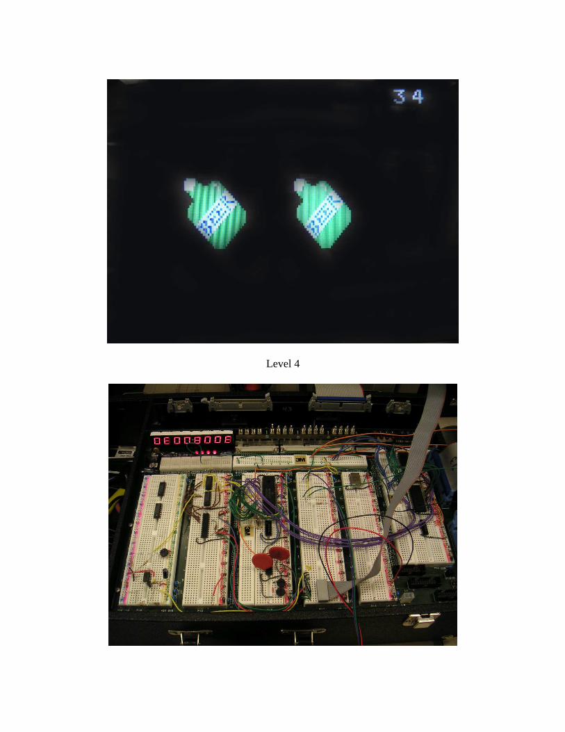
Level 4

Video Circuit
Sound Circuit