Video Communication Networks - University of Illinois …ds/Papers/Scho05.pdfVideo Communication...
56
Video Communication Networks Dan Schonfeld Multimedia Communications Laboratory Department of Electrical and Computer Engineering (M/C 154) 851 South Morgan Street 1020 SEO University of Illinois Chicago, IL 60607-7053 [email protected] Abstract In this presentation, a broad overview of video communication networks is provided. Numerous video communication applications are currently being developed including digital television, video streaming, video-on-demand, and video conferencing. Efficient storage and communication requires video data to be represented in compressed form. Various video compression standards have been developed by industrial organizations. However, among them the MPEG-2 compression standard still remains the most popular. It is currently the most powerful compression scheme for high-quality data representation and has been adopted by HDTV and DVD. For simplicity, this presentation will focus primarily on the MPEG-2 video compression standard. The basic techniques used for video communication are illustrated over a variety of communication networks: Hybrid Fiber-Coax, Digital Subscriber Loop, Wireless, Fiber Optics, Integrated Services Digital Network, ATM, and Internet Protocol networks. The quality of video communications, especially over the Internet, is of critical concern for practical applications. Numerous protocols designed to allow users to enhance the quality-of-service of video transmission over communication networks have been proposed. Several of these protocols are described including MBONE, Real-Time Transport Protocol, Real-Time Transport Control Protocol, Real-Time Streaming Protocol, Session Initiation Protocol, Resource Reservation Protocol, and DiffServ Protocol. 1. Introduction Paul Baran from the RAND Corporation first proposed the notion of a distributed communication network in 1964. His aim was to develop a decentralized communication system that could survive the impact of a nuclear attack. This proposal employed a new approach to data communication based on packet switching. Construction of a communication network based on packet switching was initiated by the Department of Defense through the Advanced Research Projects Agency (ARPA). This agency commissioned the ARPANET, later known as the Internet, in 1969. The ARPANET was initially an experimental communication network that consisted of four nodes: UCLA, UCSB, SRI, and the University of Utah.
-
Upload
phungxuyen -
Category
Documents
-
view
214 -
download
1
Transcript of Video Communication Networks - University of Illinois …ds/Papers/Scho05.pdfVideo Communication...

Video Communication Networks
Dan Schonfeld
Multimedia Communications Laboratory Department of Electrical and
Computer Engineering (M/C 154) 851 South Morgan Street � 1020 SEO
University of Illinois Chicago, IL 60607-7053
Abstract In this presentation, a broad overview of video communication networks is provided. Numerous video communication applications are currently being developed including digital television, video streaming, video-on-demand, and video conferencing. Efficient storage and communication requires video data to be represented in compressed form. Various video compression standards have been developed by industrial organizations. However, among them the MPEG-2 compression standard still remains the most popular. It is currently the most powerful compression scheme for high-quality data representation and has been adopted by HDTV and DVD. For simplicity, this presentation will focus primarily on the MPEG-2 video compression standard. The basic techniques used for video communication are illustrated over a variety of communication networks: Hybrid Fiber-Coax, Digital Subscriber Loop, Wireless, Fiber Optics, Integrated Services Digital Network, ATM, and Internet Protocol networks. The quality of video communications, especially over the Internet, is of critical concern for practical applications. Numerous protocols designed to allow users to enhance the quality-of-service of video transmission over communication networks have been proposed. Several of these protocols are described including MBONE, Real-Time Transport Protocol, Real-Time Transport Control Protocol, Real-Time Streaming Protocol, Session Initiation Protocol, Resource Reservation Protocol, and DiffServ Protocol. 1. Introduction Paul Baran from the RAND Corporation first proposed the notion of a distributed communication network in 1964. His aim was to develop a decentralized communication system that could survive the impact of a nuclear attack. This proposal employed a new approach to data communication based on packet switching. Construction of a communication network based on packet switching was initiated by the Department of Defense through the Advanced Research Projects Agency (ARPA). This agency commissioned the ARPANET, later known as the Internet, in 1969. The ARPANET was initially an experimental communication network that consisted of four nodes: UCLA, UCSB, SRI, and the University of Utah.

Throughout the 1970s, various protocols had been adopted to facilitate services such as remote connection (telnet), file transfer (ftp), electronic mail, and news distribution. Initially, the ARPANET used the Network Control Protocol (NCP) for network and transport services. In 1983, the now ubiquitous TCP/IP protocol suite � Transport Control Protocol (TCP) and Internet Protocol (IP) stack developed in the early 1970s by Cerf and Khan for packet communication networks � had replaced NCP.
Evolution of the Internet was accelerated by the creation of the NSFNET in 1986. In its infancy, the NSFNET used a backbone consisting of five supercomputer centers connected at 56 Kbps. The NSFNET backbone, managed by NSF and Merit Corp. � a partnership formed by IBM and MCI � served in excess of 10,000 nodes in 1987. To satisfy the increased demand on the Internet the NSFNET backbone was upgraded to T-1 (1.544 Mbps) in 1988. The Internet grew very rapidly to encompass over 100,000 nodes by 1989 connecting research universities and government organizations around the world. Management of the NSFNET backbone was delegated to Advanced Network and Services, Inc. (ANS) � an independent non-profit organization spun off from the partnership between Merit, IBM, and MCI.
Among the most important contributors to the proliferation of the Internet was the release of the World Wide Web (WWW) in 1991. Tim Berners-Lee proposed the WWW for the Corporation for Education and Research Networking (CERN) � the European center for nuclear research � in 1989. The Web grew out of a need for physics researchers from around the world to collaborate using a large and dynamic collection of scientific documents. The WWW provides a powerful framework for accessing linked documents throughout the Internet. The wealth of information available over the WWW has attracted the interest of commercial businesses and individual users alike. Its enormous popularity is enhanced by the graphical interfaces available for browsing multimedia information over the Internet. The NSFNET backbone was upgraded to T-3 (44.736 Mbps) in 1991. Efforts to incorporate multimedia services were advanced with the introduction of the Multicast Backbone (MBONE) in 1992. The MBONE network intended to serve multicast real-time traffic over the Internet. It provided users with the capability to transmit audio and video multicast streams.
The enormous popularity of the WWW grew to over 10 million nodes by the mid 1990s. The NSF decommissioned the NSFNET and delegated commercial traffic to private backbones in 1995. The same year, the NSF has restructured its data networking architecture by providing the very high speed Backbone Network Service (vBNS) through a partnership with MCI Worldcom. In 1999, the vBNS was upgraded from OC-12 (622 Mbps) to OC-48 (2.5 Gpbs).
The NSF efforts to improve the communication network backbone were coupled with two related initiatives: Next Generation Internet (NGI) and Internet 2. In 1996, President Clinton introduced the NGI initiative in an effort to provide a faster and higher capacity Internet. This initiative was continued by the Large Scale Networking (LSN) coordinating group in an effort to advance networking technologies and services.
Internet 2 is an independent project coordinated by academic institutions whose goal is to accelerate the development of the Internet. This goal is addressed by deploying advanced network applications and technologies. Much of the effort of Internet 2 members has focused on the Abilene network. Abilene is a high-performance backbone

network formed by partnership between Internet 2 and industry in 1999. Initially, Abilene provided communication at OC-48 (2.5 Gbps). Currently, the Abilene backbone has been upgraded to OC-192 (10 Mbps). Improvements in communication networks� infrastructure are aimed at improving data communications and expanding applications. Efforts are underway to increase the communication bandwidth and support real-time services such as audio and video communications. The tremendous bandwidth required by video communications makes it among the most challenging of the applications envisioned in the next generation networks. In the future, video communication networks will be used for a variety of applications including digital television, video streaming, video-on-demand, and video conferencing. An illustration of video communication services is depicted in Fig. 1. In this chapter, we will explore the current techniques used for video communications over data networks.
Figure 1: Video Communication Services
Distance Learning Telemedicine Videoconferencing
Broadcast
Mobile Computer Multimedia E-mail Interactive Television
VoD
Network

2. Video Compression Standards 2.0 Introduction Video communications almost always relies on compressed video streams. Transmission of raw (uncompressed) video streams is impractical: Excessive bandwidth is needed for both the communication channel and storage devices. Moreover, computer processing and memory limitations often impose serious constraints on transmission rates. Representation of video streams in compressed form is therefore required for efficient video communication systems. Numerous video compression standards have been released by international organizations over the past decade. The main organizations involved in adoption of video communication standards include the International Standards Organization (ISO) and International Telecommunications Union (ITU). Currently, the most widely used video compression standard is MPEG-2. It has been adopted for video communication applications such as HDTV and DVD. Our focus in this presentation will thus be on the MPEG-2 standard. 2.1 Overview Two video compression standard families have emerged: Motion Photographic Expert Group (MPEG) and H.26X. MPEG standards have been developed by the ISO and are primarily aimed at motion picture storage and communications. H.26X proposed by the ITU on the other hand focus on video-conferencing applications. The sequence of compression standards generated by MPEG and H.26X are very closely related. Many of the techniques adopted by MPEG�s latest compression standard borrow from recent developments in H.26X�s latest release, and vice-versa. Earlier efforts at video compression were based on methods developed for image compression. Specifically, the ubiquitous Joint Photographic Experts Group (JPEG) image compression standard. JPEG is used for compression of continuous-tone still images. This compression standard is based on the Huffman and Run-Length encoding of quantized coefficients of the Discrete Cosine Transform (DCT) of image blocks. The widespread use of the JPEG standard is motivated by the fact that it consistently produces compression ratios in excess of 20:1. Video compression can be accomplished by using image compression techniques on consecutive video frames. Direct application of JPEG on video sequences is known as Motion JPEG (MJPEG). MJPEG encodes each individual picture in the video sequence separately using JPEG compression. This approach is used when random access to each picture is essential in applications such as video editing and enhanced VCR-functionality. MJPEG compressed video yields data rates in the range of 8-10 Mbps. MJPEG is used in high-quality video applications in the motion picture industry. Compression efficiency of MJPEG is commensurate to what is achieved by JPEG in image encoding. JPEG exploits the spatial redundancy of the image for data compression. Correlation between neighboring pixels within image frames is extracted. This approach however fails to benefit from the high temporal redundancy of consecutive image frames in video sequences.

A video compression standard that exploits both spatial and temporal redundancy was proposed by MPEG-1. Its goal was to produce VCR NTSC (352 x 240) quality video compression to be stored on CD-ROM (CD-I and CD-Video format) using a data rate of 1.2 Mbps. This approach is based on the arrangement of frame sequences into a Group Of Pictures (GOP) consisting of four types of pictures: I-Picture (Intra), P-Picture (Predictive), B-Picture (Bidirectional), and D-Picture (DC). I-Pictures are Intraframe JPEG encoded pictures that are inserted at the beginning of the GOP. P and B-Pictures are Interframe motion compensated JPEG encoded macroblock residual difference pictures that are interspersed throughout the GOP.1 MPEG-1 restricts the GOP to sequences of fifteen frames in progressive mode. MPEG-1 provides for the integration and synchronization of the audio and video streams. This is accomplished by multiplexing and including timestamps in both the audio and video streams from a 90 KHz system clock. The next goal of the MPEG community was to develop a broadcast-quality video compression standard. A standard developed based on the fundamental concepts present in the MPEG-1 standard had emerged. This standard is the well-known MPEG-2 video compression standard. Its popularity and efficiency in high-quality video compression resulted in the expansion of the standard to support higher resolution video formats including High Definition Television (HDTV).2 The HDTV Grand Alliance standard has adopted the MPEG-2 video compression and transport stream standards in 1996.3 MPEG-2 supports four resolution levels: low (352 x 240), main (720 x 480), high-1440 (1440 x 1152), and high (1920 x 1080). The MPEG-2 compressed video data rates are in the range of 3�100 Mbps.4 Although the principles used to encode MPEG-2 are very similar to MPEG-1, it provides much greater flexibility by offering several profiles that differ in the presence or absence of B-Pictures, chrominance resolution, and coded stream scalability.5 MPEG-2 supports both progressive and interlaced modes.6 Significant improvements have also been introduced in the MPEG-2 system level. In its next mission the MPEG community attempted to address low-bandwidth video compression at data rate of 64 Kbps that can be transmitted over a single N-ISDN B channel. This goal has evolved to the development of flexible scalable extendable interactive compression streams that can be used with any communication network for universal accessibility (e.g., Internet and wireless networks). The resulting standard known as MPEG-4 is a genuine multimedia compression standard that supports audio and video as well as synthetic and animated images, text, graphics, texture, and speech synthesis. A dramatic change in approach emphasizing content-based hierarchical Audio-Visual Object (AVO) representation and composition was used in the development of the MPEG-4 standard. A video object at a given point in time is a Video Object Plane (VOP). Each VOP is encoded separately according to its shape, motion, and texture. The shape encoding of a VOP provides a pixel map or a bitmap of the shape of the object. The motion and texture encoding of a VOP can be obtained in a manner similar to that used in
1 D-Pictures are used exclusively for low-resolution high-speed video scanning. 2 The MPEG-3 video compression standard, which was originally intended for HDTV, was later cancelled. 3 The HDTV Grand Alliance standard, however, has selected the Dolby Audio Coding 3 (AC-3) audio compression standard. 4 The HDTV Grand Alliance standard video data rate is approximately 18.4 Mbps. 5 The MPEG-2 video compression standard, however, does not support D-Pictures. 6 The interlaced mode is compatible with the field format used in broadcast television interlaced scanning.

MPEG-2. A multiplexer is used to integrate and synchronize the VOP data and composition information�position, orientation, and depth�as well as other data associated with the AVOs in a specified bitstream. MPEG-4 provides universal accessibility supported by error robustness and resilience, especially in noisy environments at very low data rates (less than 64 Kbps): bitstream resynchronization, data recovery, and error concealment. These features are particularly important in mobile multimedia communication networks. Despite the novel approach and initial excitement surrounding the release of the MPEG-4 standard, its use in practical applications has been marginal. The limitations of MPEG-4 stem from the difficulty in efficient extraction of AVOs from the video bitstream. Current performance of high-precision real-time video segmentation and tracking algorithms is inadequate. Most current implementations of the MPEG-4 standard rely on a version of the standard known as simple profile. In this profile the AVO are not utilized; they effectively correspond to the entire video frame. The resulting implementation of MPEG-4 simple profile is therefore little different from its predecessor MPEG-2. It is envisioned that the use of AVOs will ultimately provide superior low-rate video compression. However, the enormous success of the recently released H.264 standard has raised this premise into question. The H.264 has been demonstrated to generate better low-rate video compression than MPEG-4 without the use of AVOs. A version of the H.264 standard has subsequently been incorporated into MPEG-4 � it is known as MPEG-4 JVT. Parallel to the efforts of the MPEG community, the H.26X family of video compression standards was released. Emphasis in H.26X video compression is on video-conferencing applications over various communication networks. Real-time constraints are often imposed and require the elimination of various features present in the corresponding MPEG standards. 2.2 MPEG-2 Video Compression Standard MPEG-2 video compression relies on block-coding based on the Discrete Cosine Transform (DCT). Specifically, each frame is divided into 8× 8 blocks which are transformed using DCT. Quantization of the transformed blocks is obtained by dividing the transformed pixel values by corresponding elements of a quantization matrix and rounding the ratio to the nearest integer. The transformed and quantized block values are scanned using a zig-zag pattern to yield a one-dimensional sequence of the entire frame. A hybrid variable length coding scheme that combines Huffman coding and run-length coding is used for symbol encoding. The procedure outlined is used for both intraframe and interframe coding. Intraframe coding is used to represent an individual frame independently. The scheme used for intraframe coding is essentially identical to JPEG image compression. An intraframe-coded picture in the video sequence is referred to as an Intra-Picture (I-Picture). Interframe coding is used to increase compression by exploiting temporal redundancy. Motion compensation is employed to predict the content of the frame. Coding of its residual error represents the predicted frame. The frame is divided into 16× 16 macroblocks (2× 2 blocks). An optimal match of each macroblock in the neighboring frame is determined. A motion vector is used to represent the offset between

the macroblock and its �best-match� in the neighboring frame. A residual error is computed by subtracting the macroblock from its �best match.� Coding of the residual error image proceeds in the same manner as intraframe coding. Coding of the motion vector field is performed separately using difference coding and variable length coding. An interframe-coded picture in the video sequence that restricts the search to the previous frame is referred to as a Predicted-Picture (P-Picture); whereas, those pictures that allow for either the previous or subsequent frames is referred to as a Bidirectional-Picture (B-Picture). Rows of macroblocks in the picture are called Slices. The collection of slices forms a Picture. Groups of Pictures (GOP) refer to sequences of pictures. A GOP is used to specify a group of consecutive frames and their picture types. For example, a typical GOP may consist of 15 frames with the following picture types: IBBPBBPBBPBBPBB. This scheme would allow for random access and error propagation that does not exceed intervals of ½ second assuming the video is streamed at a rate of 30 frames per second. 2.3 MPEG-2 Systems Standard The compressed image and video data is stored and transmitted in a standard format known as a compression stream. The discussion in this section will be restricted exclusively to the presentation of the video compression stream standards associated with the MPEG-2 systems layer: elementary stream (ES), packetized elementary stream (PES), program stream (PS), and transport stream (TS). The MPEG-2 systems layer is responsible for the integration and synchronization of the elementary streams (ES): audio and video streams, as well as an unlimited number of data and control streams that can be used for various applications such as subtitles in multiple languages. This is accomplished by first packetizing the ESs thus forming the packetized elementary streams (PES). These PESs contain timestamps from a system clock for synchronization.
Video
Audio
PS
TS
Video
Encoder
Packetizer
Packetizer
Audio
Encoder
Clock
Program Stream
Multiplexer
Transport Stream
Multiplexer

Figure 2: MPEG-2 Audio and Video Systems Layer The PESs are subsequently multiplexed to form a single output stream for transmission in one of two modes: program stream (PS) and transport stream (TS). The PS is provided for error-free environments such as storage in CD-ROM. It is used for multiplexing PESs that share a common time-base, using long variable-length packets.7 The TS is designed for noisy environments such as communication over ATM networks. This mode permits multiplexing streams (PESs and PSs) that do not necessarily share a common time-base, using fixed-length (188 bytes) packets. An example of the MPEG-2 systems layer illustrating the multiplexing of the packetized audio and video elementary streams is depicted in Fig. 2. 2.3.1 MPEG-2 Elementary Stream As indicated earlier, MPEG-2 systems layer supports an unlimited number of elementary streams (ES). Our focus is centered on the presentation of the ES format associated with the video stream. The structure of the video ES format is dictated by the nested MPEG-2 compression standard: video sequence, group of pictures (GOP), pictures, slices, and macroblocks. The video ES is defined as a collection of access units (pictures) from one source. An illustration of the video ES format is depicted in Fig. 3. A corresponding glossary of the video ES format is provided in Table 1. Note that the unshaded segment of the video ES format presented in Fig. 3 is used to denote that any permutation of the fields within this segment can be repeated as specified by the video compression standard.
SH
SE
EUD0
GOPH
EUD1
PH
PCE
EUD2
PDS
SDMB
SE
Figure 3: Video Elementary Stream Format
7 The MPEG-2 program stream (PS) is similar to the MPEG-1 systems stream.

Abbr Function SH Sequence Header SE Sequence Extension
EUD0 Extension and User Data 0 GOPH Group Of Picture Header EUD1 Extension and User Data 1
PH Picture Header PCE Picture Coding Extension
EUD2 Extension and User Data 2 PDS Picture Data containing Slices
SDMB Slices Data containing Macro-Blocks SE Sequence End
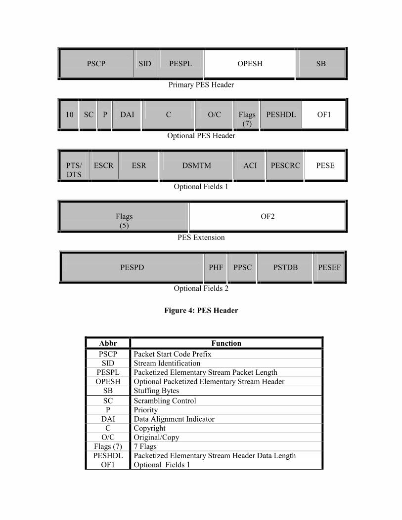
Table 1: Video Elementary Stream Format Glossary 2.3.2 MPEG-2 Packetized Elementary Stream The MPEG-2 systems layer packetizes all ESs�audio, video, data, and control streams�thus forming the packetized elementary streams (PES). Each PES is a variable-length packet with a variable format that corresponds to a single ES. The format of the PES header is defined by the stream ID (SID) used to identify the type of ES. The PES packet length (PESPL) indicates the number of bytes in the PES packet. The scrambling mode is represented by the scrambling control (SC). The PES header data length (PESHDL) indicates the number of bytes in the optional PES header (OPESH) fields, as well as stuffing bytes (SB) used to satisfy the communication network requirements. The PES header contains timestamps to allow for synchronization by the decoder. Two different timestamps are used: presentation timestamp (PTS) and decoding timestamp (DTS). The PTS specifies the time at which the access unit should be removed from the decoder buffer and presented. The DTS represents the time at which the access unit must be decoded. The DTS is optional and it is only used if the decoding time differs from the presentation time.8 The elementary stream clock reference (ESCR) indicates the intended time of arrival of the packet at the system target decoder (STD). The rate at which the STD receives the PES is indicated by the elementary stream rate (ESR). Error checking is provided by the PES cyclic redundancy check (PESCRC).
The pack header field (PHF) is a PS pack header. The program packet sequence counter (PPSC) indicates the number of system streams. The STD buffer size is specified by the P-STD buffer (PSTDB) field.
A nested representation of the PES header is depicted in Fig. 4. The corresponding glossary of the PES header is provided in Table 2. Note that the unshaded boxes presented in Fig. 4 are used to represent optional fields in the PES header.
8 This is the situation for MPEG-2 video elementary stream profiles that contain B-Pictures.
PSCP
SID
PESPL
OPESH
SB
Primary PES Header
10
SC
P
DAI
C
O/C
Flags
(7)
PESHDL
OF1
Optional PES Header
PTS/ DTS
ESCR
ESR
DSMTM
ACI
PESCRC
PESE
Optional Fields 1
Flags (5)
OF2
PES Extension
PESPD PHF
PPSC
PSTDB
PESEF
Optional Fields 2
Figure 4: PES Header
Abbr Function PSCP Packet Start Code Prefix SID Stream Identification
PESPL Packetized Elementary Stream Packet Length OPESH Optional Packetized Elementary Stream Header
SB Stuffing Bytes SC Scrambling Control P Priority
DAI Data Alignment Indicator C Copyright
O/C Original/Copy Flags (7) 7 Flags PESHDL Packetized Elementary Stream Header Data Length
OF1 Optional Fields 1

PTS/DTS Presentation Time-Stamps / Decoding Time-Stamps ESCR Elementary Stream Clock Reference ESR Elementary Stream Rate
DSMTM DSM Trick Mode ACI Additional Copy Information
PESCRC Packetized Elementary Stream Cyclic Redundancy Check PESE Packetized Elementary Stream Extension
Flags (5) 5 Flags OF2 Optional Fields 2
PESPD Packetized Elementary Stream Private Data PHF Pack Header Field
PPSC Program Packet Sequence Counter PSTDB P-STD Buffer PESEF Packetized Elementary Stream Extension Field
Table 2: PES Header Glossary 2.3.3 MPEG-2 Program Stream A program stream (PS) multiplexes several PESs, which share a common time-base, to form a single stream for transmission in error-free environments. The PS is intended for the storage and retrieval of programs from digital storage media such as CD-ROM. The PS uses relatively long variable-length packet. For a more detailed presentation of the MPEG-2 PS refer to X. 2.3.4 MPEG-2 Transport Stream A transport stream (TS) permits multiplexing streams (PESs and PSs) that do not necessarily share a common time-base for transmission in noisy environments. The TS is designed for broadcasting over communication networks such as ATM networks. The TS uses small fixed-length packets (188 bytes) that make them more resilient to packet loss or damage during transmission. The TS provides the input to the transport layer in the OSI reference model.9 The TS packet is composed of a four-byte header followed by 184 bytes shared between the variable-length adaptation field and the TS packet payload. An illustration of the TS header is depicted in Fig. 5. The corresponding glossary of the TS header is provided in Table 3. Note that the unshaded box appearing in Fig. 5 is used to represent the optional adaptation field (AF).
9 The transport stream (TS), however, is not considered as part of the transport layer.

SB
TEI
PUSI
TSC
TP
PID
AFC
CC
AF
Figure 5: TS Header
Abbr Function SB Synchronization Byte TEI Transport Error Indicator
PUSI Payload Unit Start Indicator TSC Transport Scrambling Control TP Transport Priority PID Packet Identifier AFC Adaptation Field Control CC Continuity Counter AF Adaptation Field (Optional)
Table 3: TS Header Glossary The TS header includes a synchronization byte (SB) designed for detection of the
beginning of each TS packet. The transport error indicator (TEI) points to the detection of an uncorrectable bit error in this TS packet. The payload unit start indicator (PUSI) is used to ascertain if the TS payload contains PES packets or program-specific information (PSI). The packet ID (PID) identifies the type and source of payload in the TS packet. The presence or absence of the adaptation field (AF) and payload is indicated by the adaptation field control (AFC). The continuity counter (CC) provides the number of TS packets with the same PID, which is used to determine packet loss. The optional adaptation field (AF) contains additional information that need not be included in every TS packet. One of the most important fields in the AF is the program clock reference (PCR). The PCR is a 42-bit field composed of a 9-bit segment incremented at 27 MHz as well as a 33-bit segment incremented at 90 KHz.10 The PCR is used along with a voltage controlled oscillator as a time reference for synchronization of the encoder and decoder clock.
A PES header must always follow the TS header and possible AF. The TS payload may consist of the PES packets or PSI. The PSI provides control and management information used to associate particular ESs with distinct programs. A program is once again defined as a collection of ESs that share a common time-base. This is accomplished by means of a program description provided by a set of PSI associated signaling tables (AST): program association tables (PAT), program map tables (PMT), network information tables (NIT), and conditional access tables (CAT). The PSI tables are sent periodically and carried in sections along with cyclic redundancy check (CRC) protection in the TS payload.
10 The 33-bit segment incremented at 90 KHz is compatible with the MPEG-1 system clock.

I Picture
P Picture
P Picture
Elementary Stream (ES)
PES
Header
I Picture
PES
Header
P Picture
Packetized Elementary Stream (PES)
0 187B 0 187B 0 187B
TS
Header
PES Data
TS
Header
PES Data
TS
Header
PES Data
Stuffing
Transport Stream (TS)
Figure 6: TS Packets
An example illustrating the formation of the TS packets is depicted in Fig. 6. The choice of the size of the fixed-length TS packets�188 bytes�is motivated by the fact that the payload of the ATM Adaptation Layer-1 (AAL-1) cell is 47 bytes. Therefore, four AAL-1 cells can accommodate a single TS packet. A detailed discussion of the mapping of the TS packets to ATM networks is presented in the next section. 3. Video Communication Networks 3.0 Introduction A wide array of communication networks has proliferated over the past few decades. The goal of many communication networks is to provide as much communication bandwidth as possible while controlling the infrastructure costs. Efforts to provide inexpensive communication mediums have focused on exploiting the infrastructure of existing communication systems. For example, the hybrid of fiber optics and coaxial cable used in the cable television system has been adapted for data communications. Similarly, the web of copper wiring used in the telephone system has also been utilized for digital transmission. Moreover, the traditional use of �air� as a conduit in wireless systems�

radio and television, cellular telephony, etc.�has recently been extended to accommodate high-bandwidth data communications.
Some applications require high-bandwidth communication networks that do not compromise transmission quality to reduce infrastructure costs. Examples of applications that impose severe bandwidth demands are communication backbones for wide and metropolitan area networks. On occasion, high volume traffic in local area networks will also require a high-bandwidth communication infrastructure. Communication networks that need extremely high-bandwidth generally rely on fiber optics as the communication medium. A common deployment of high-bandwidth communication networks is based on Asynchronous Transfer Mode (ATM) networks. ATM networks are extremely fast networks that are usually, although not necessarily, implemented using fiber optics. In some networks, ATM provides a protocol stack that characterizes the entire communication network. In most instances, however, ATM serves to represent the lower-level layers in a communication network such as the Internet.
A general design philosophy adopted is to provide very high-bandwidth communication for the networks� backbone and exploit existing infrastructure to connect individual users. This methodology is rooted in economics: the investment costs in installation of a powerful backbone will serve all customers and can be easily recovered. Deployment costs of high-bandwidth communication lines to each individual user, on the other hand, are excessive and therefore avoided. Indeed, tremendously powerful communication backbones have been implemented in the past few decades and are continuously evolving. Practically, one of the main difficulties presented today is the local distribution problem: how to efficiently connect individual customers to the communication networks� backbone? This problem is also colloquially referred to as the �the last mile problem.� Various solutions have been proposed by the cable television, telephone, and wireless industries. Cable television and wireless communication systems are inherently broadcast systems which may pose some limitations for many communication network applications. Telephone systems are based on point-to-point communications which may be exploited for linking the backbone to customers� homes.
In this section, an overview of some of the main communication networks and their utility for multimedia communication applications is presented. The cable television network�known as the Hybrid Fiber-Coax (HFC) network�is discussed in Section 3.1. Adaptation of wireline telephone networks to computer networking through the Digital Subscriber Loop (DSL) protocol is presented in Section 3.2. The evolution of various wireless networks to high-bandwidth communication applications is sketched in Section 3.3. The widest bandwidth communication conduit is provided by fiber optics which are discussed in Section 3.4. A brief presentation of digital communications based on Integrated Services Digital Networks (ISDN) is provided in Section 3.5. Finally, the use of Asynchronous Transfer Mode (ATM) networks for multimedia communications is discussed in Section 3.6. For brevity, this presentation will be restricted exclusively to video communications based on the MPEG-2 compression standard. 3.1 Hybrid Fiber-Coax Networks (HFC) Cable television providers have installed an extensive communication network for delivery of television channels to the home. The main communication conduit used by the cable television industry is the coaxial cable. Coaxial cables are usually deployed between

homes and a central point known as an optical node. Several optical nodes are connected via optical fibers to a head end. The cable television network is thus a mixture of both fiber optics and coaxial cable known as a Hybrid Fiber Coax (HFC) network. Bandwidth limitations in HFC networks are primarily due to the coaxial cable. The bandwidth of coaxial cable is either 300-450 MHz or 750 MHz. The number of analog channels carrying a 6-MHz NTSC signal accommodated on coaxial cable is 50-75 or 125 channels, respectively. Communication networks deployed over existing cable television systems must accommodate both data communications and television broadcasting. Cable television systems rely on the unused frequency in the 5-42 MHz band for upstream channels. Normal cable television channels in the 54-550 MHz region are maintained. Downstream channels are allocated in the frequency range available above 550 MHz.11 Downstream channels represent the data using Quadrature Amplitude Modulation (QAM) for signal modulation. Generally, QAM-64 is used to provide data rate of 27 Mbps. At times, the cable quality is sufficiently good to use QAM-256 which allows for about 39 Mbps. Upstream channels, on the other hand, rely on Quadrature Phase Shift Keying (QPSK) for signal modulation. Consequently, only 2 bits per baud are used for upstream communication; whereas, either 6 or 8 bits per baud are provided for downstream channels. The cable television system is a broadcasting system and bandwidth resources must therefore be shared among all customers. Let us assume that 50 channels can be used for data communications and must accommodate no more than 500 customers. In this scenario, a dedicated 4 Mbps data communication channel can be allocated to each home. This communication rate would be sufficient to handle MPEG-2 video streams.
In reality, however, existing cable television systems cannot afford to devote 50 channels exclusively to a limited number of customers not exceeding 500 homes. Most current cable television providers do not guarantee data communication rates above 700 Kbps. At these rates, video communications using the MPEG-2 compression standard could not be conducted. 3.2 Digital Subscriber Loop (DSL) A long tradition has evolved in an effort to use the public switched telephone network (PSTN) for data communications.12 The main advantage of PSTN is that it is widely accessible to virtually all homes. Modem technology for dial-up service over PSTN have improved and can reach rates of up to 56 Kbps. A communication standard�H.324�has been developed for multimedia communications over PSTN. Video communications, however, requires much wider bandwidth using most compression standards.
The telephone industry had invested a tremendous amount of money to build a complex infrastructure that provides copper twisted pair wiring into virtually every home. In an effort to leverage this investment, the telephone industry has proposed a communication standard known as the Digital Subscriber Loop (DSL). The basic idea
11 In Europe, the low end of the standard television signal is 65 MHz and channels are 6-8 MHz to accommodate the PAL and SECAM television signals. 12 The telephone network is also referred to as the Plain Old Telephone System (POTS).

behind DSL is to present an efficient modulation scheme that will exploit the copper wires for data communications.
Traditionally, the telephone systems imposes a filter in the end office that limits voice communications to 4 KHz. DSL circumvents this restriction by switching data signals to avoid the filters in the end office. Fundamental bandwidth limitations are consequently due to the physical properties of the copper twisted pair in the local loop.
The approach taken to the design of DSL uses a concept known as Discrete MultiTone (DMT). The spectrum available on the local loop is about 1.1 MHz. DMT divides the bandwidth among 256 channels. Each channel has a bandwidth of 4.3125 KHz. Channel 0 is reserved for POTS�Plain Old Telephone Service. Channels 1-5 are reserved as guard bands to avoid interference between the voice and data channels. Additionally, one channel is used for upstream control and another channel for downstream control. The remaining 248 channels are available for data communications. A common split of the data channels is to allocate 32 channels for upstream data and the remaining 216 channels for downstream data. This implementation, which provides higher bandwidth for downstream than upstream data communications, is known as Asymmetric DSL (ADSL).
High-bandwidth communication over the channels is achieved by the use of an efficient signal modulation scheme. Each channel provides a sampling rate of 4000 baud. Quadrature Amplitude Modulation-16 (QAM-16) with up to 15 bits per baud is used for signal modulation. For relatively short distances, DSL can provide communication at rates that exceed 8 Mbps. For instance, the ADSL standards ANSI T1.413 and ITU G.992.1 allow for data rates of 8 Mbps downstream and 1 Mbps upstream. Typically, premium service data rates are offered at 1 Mbps downstream and 256 Kbps upstream. Standard service is further restricted to 512 Kbps downstream and 64 Kbps upstream.
Although extremely high rates can be provided over DSL for very short distances, most practical scenarios demand longer transmission lengths. The bandwidth provided by DSL decreases rapidly as the transmission distance increases. Therefore, most telephone companies will only guarantee all users data communications over DSL at rates of 128 Kbps. These rates are insufficient for video communications based on most compression standards. 3.3 Wireless Networks Historically, wireless networks date to ancient civilization. Fire signals were used for messaging between hilltops. Modern wireless communications dates back to the Italian physicist Gugliemo Marconi who, in 1901, used a wireless telegraph with Morse code to establish communication to a ship.
Wireless networks have been developed for many different applications. Traditionally, wireless networks were used to refer to cellular networks for speech communications. Evolution of wireless networks has been designed to accommodate data communications. More recently, wireless networks have been employed as local area networks and wireless local loops.
Wireless networks were until recently primarily devoted to paging as well as real-time speech communications. First generation wireless communication networks were analog systems. The most widely used analog wireless communication network is known

as the Advanced Mobile Phone Service (AMPS).13 The AMPS system is based on frequency-division multiple access (FDMA) and uses 832 30 KHz transmission channels in the range of 824�849 MHz and 832 30 KHz reception channels in the range of 869�894 MHz. Second generation wireless communication networks are digital systems based on two approaches: time-division multiple access (TDMA) and code-division multiple access (CDMA). Among the most common TDMA wireless communication networks are the IS-54 and IS-136 as well the Global Systems for Mobile communications (GSM). The IS-54 and IS-136 are dual mode (analog and digital) systems that are backward compatible with the AMPS system.14 In IS-54 and IS-136, the same 30 KHz channels are used to accommodate three simultaneous users (six time slots) for transmission at data rates of approximately 8 Kbps. GSM originated in Europe and is a pure digital system based on both FDMA and TDMA. It consists of 50 200 KHz bands in the range of 900 MHz used to support eight separate connections (eight time slots) for transmission at data rates of 13 Kbps.15 The second approach to digital wireless communication networks is based on CDMA. The origins of CDMA are based on spread-spectrum methods that date back to secure military communication applications during the Second World War.16 The CDMA approach uses direct-sequence spread-spectrum (DSSS) which provides for the representation of individual bits by pseudo-random chip sequences. Each station is assigned a unique orthogonal pseudo-random chip sequence. The original bits are recovered by determining the correlation (inner product) of the received signal and the pseudo-random chip sequence corresponding to the desired station. The current CDMA wireless communication network is specified in IS-95.17 In IS-95, a channel bandwidth of 1.25 MHz is used for transmission at data rates of 8 Kbps or 13 Kbps.
Efforts at integration of cellular networks to packet-based data communication over wireless networks have been made. This allows for data communication between wireless devices and fixed terminals connected to the Internet. For example, a mobile user could use his laptop to browse the web. Specifically, the General Packet Radio Service (GPRS) wireless access network is an overlay packet network that is employed in D-AMPS and GSM systems. GPRS provides data communications at data rates in the range of 9-21.4 Kbps using a single time slot. An improved wireless access technology, known as Enhanced Data rates for GSM Evolution (EDGE), can be used to provide data rates in the range of 8.8-59.2 Kbps using a single time slot. Use of multiple time slots can increase the data rates as high as 170 Kbps. Plans have been proposed for the implementation of the third generation wireless communication networks in the International Mobile Communications-2000 (IMT-2000). The motivation of IMT-2000 is to expand mobile communications to multimedia applications as well as to provide access to existing networks (e.g., ATM and Internet). This is accomplished by providing circuit and packet switched channel data connection as
13 The AMPS system is also known as TACS and MCS-L1 in England and Japan, respectively. 14 The Japanese JDC system is also a dual mode (analog and digital) system that is backward compatible with the MCS-L1 analog system. 15 The implementation of the GSM system in the range of 1.8 GHz is known as DCS-1800. 16 In 1940, the actress Hedy Lamarr, at the age of 26, invented a form of spread-spectrum, known as frequency-hopping spread-spectrum (FHSS). 17 The IS-95 standard has recently been referred to as CDMA-One.

well as larger bandwidth used to support much higher data rates. The focus of IMT-2000 is on the integration of several technologies: CDMA-2000, Wideband CDMA (W-CDMA), Universal Wireless Communications-136 (UWC-136), and Wireless Multimedia and Messaging Services (WIMS). CDMA-2000 is designed to be a wideband synchronous inter-cell CDMA based network using frequency-division duplex (FDD) mode and is backward compatible with the existing CDMA-One (IS-95). The CDMA-2000 channel bandwidth planned for the first phase of implementation will be restricted to 1.25 MHz and 3.75 MHz for transmission at data rates of up to 1 Mbps. The CDMA-2000 channel bandwidth will be expanded during the second phase of implementation to include 7.5 MHz, 11.25 MHz, and 15 MHz for transmission that will support data rates that could possibly exceed 2.4 Mbps. CDMA 2000 was proposed by Qualcomm. W-CDMA is a wideband asynchronous inter-cell CDMA (with some TDMA options) based network that provides for both frequency-division duplex (FDD) and time-division duplex (TDD) operations. W-CDMA is designed to interwork with the existing GSM and provides possible harmonization with WIMS. The W-CDMA channel bandwidth planned for the initial phase of implementation is 5 MHz for transmission at data rates of up to 480 Kbps. The W-CDMA channel bandwidth planned for a later phase of implementation will reach 10 MHz and 20 MHz for transmission that will support data rates of up to 2 Mbps. W-CDMA has been proposed by Ericsson and advocated by the European Union, which called it Universal Mobile Telecommunications System (UMTS). UWC-136 is envisioned to be an asynchronous inter-cell TDMA based system that permits both frequency-division duplex (FDD) and time-division duplex (TDD) modes. UWC-136 is backward compatible with the current IS-136 and provides possible harmonization with GSM. UWC-136 is a unified representation of IS-136+ and IS-136 High Speed (IS-136 HS). IS-136+ will rely on the currently available channel bandwidth of 30 KHz, for transmission at data rates of up to 64 Kbps. The IS-136 HS outdoor (mobile) channel bandwidth will be 200 KHz, for transmission at data rates of up to 384 Kbps; whereas, the IS-136 HS indoor (immobile) channel bandwidth will be expanded to 1.6 MHz for transmission that will support data rates of up to 2 Mbps. UWC-136 no longer appear to be a serious contender for adoption by industry. WIMS is planned to be a wideband asynchronous inter-cell CDMA based system using the frequency-division duplex (FDD) operation and is compatible with ISDN. The WIMS channel bandwidth scheduled for the first phase of implementation is 5 MHz, for transmission at data rates of 16 Kbps. The WIMS channel bandwidth proposed for the second phase of implementation will expand to 10 MHz and 20 MHz for transmission that will approach 2.4 Mbps. Currently, it does not seem likely that WIMS will be adopted by industry.
The larger bandwidth and significant increase in data rates supported by the various standards in IMT-2000 will facilitate video communication over wireless networks. Moreover, the packet switched channel data connection option provided by the various standards in IMT-2000 will allow for the implementation of many of the methods and protocols used for real-time IP networks for video communication over wireless networks (e.g., RTP/RTCP, RTSP, SIP, etc.).
Wireless networks also serve a very different role as local area networks. Extensions of the well known IP and ATM protocols have been adopted for wireless communications and are known as mobile IP and wireless ATM, respectively. Among the

most popular local area networks currently employed is the IEEE 802.11 standard. IEEE 802.11 provides communications at data rates of up to 11 Mbps. It is an enormously popular standard which has accounted for a high density of hubs scattered in urban areas. For this reason, some have speculated that in the future the IEEE 802.11 standard may serve a role as a wireless network that is not necessarily restricted to its local area.
On a much smaller scale, wireless networks are used to provide interconnection among various computer devices within close physical proximity. This approach allows for ease of operation and avoids the wire connections required by traditional methods. A wireless network called Bluetooth has been adopted as a standard by the computer and communication industry to achieve this goal.18 Bluetooth technology also served as the basis for the IEEE 802.15 standard for wireless personal area networks.
Wireless local loops are another example of the use of wireless networks for data communications. A common scenario is a wireless transmission between a home and a base station. In this case, wireless networks are used to address the �last mile problem.� Data rates are dependent on the distance between the client and the base station. The shorter the distance the higher the data rate that can be provided. Classifications of wireless local loops depend on their radius of service: Multichannel Multipoint Distribution Service (MMDS) and Local Multipoint Distribution Service (LMDS). MMDS provides service across distances in the range of 30 miles. MMDS data rates may not exceed 1 Mbps. It uses 198 MHz in the 2.1 and 2.5 GHz range. LMDS provides service over much shorter distances in the range of 3 miles. LMDS data rates may be as high as 100-600 Mbps. It was allotted 1.3 GHz�the single largest bandwidth allocation by the FCC�in the 28-31 GHz range.19 The IEEE 802.16 standard has been developed to provide broadband fixed wireless networking capability for LMDS applications.
Another form of wireless networks is provided by satellite communications. Video broadcasting over satellites has been conducted for many years. Both analog and digital video broadcasting have been used over satellite networks. More recent efforts have attempted to use satellites for real-time video communications. Limited success of this endeavor is due to the large number of satellites that are required to be launched into low orbit in order to reduce the communication delay. 3.4 Fiber Optics There are two main methods provided by the telephone industry for local distribution using fiber optics: Fiber To The Curb (FTTC) and Fiber To The Home (FTTH). FTTC requires the installation of optical fibers from the end office to central locations such as residential neighborhoods. These central locations are equipped with a device known as an Optical Network Unit (ONU). The ONU is the termination point of multiple copper local loops connected within the immediate vicinity. The local loops between users and the ONU are sufficiently short that it is now possible to provide much higher communication bandwidth. For example, full-duplex T1 or T2 communication networks can be run over the copper wires for transmission of MPEG-2 video channels.
18 Bluetooth technology was named after Harald Blaatand (Bluetooth) II (940-981) who was a Viking king that unified Denmark and Norway. 19 A similar approach to LMDS is used in Europe in the 40 MHz range.

An even more ambitious design is provided by FTTH. In this scheme, an optical fiber line is deployed directly into each customer�s home. Consequently, an OC-1 or OC-3 or higher carrier rates can be accommodated. These rates are extremely high and can be used for virtually any multimedia communication application desired. The prohibitive factor in FTTH is cost. Installation of fiber optics into every home is very expensive. Nonetheless, some new residences and businesses have already been wired and fitted with fiber optic communication lines. Although large-scale deployment of FTTH may not happen for several years, it is clearly our future direction. 3.5 Integrated Services Digital Network (ISDN) The Integrated Services Digital Network (ISDN) is the first public digital network. It was designed to support a large variety of date types including data, voice, and video. It is based on circuit-switched synchronous communication. ISDN uses B channels for basic traffic and D channels for return signaling. Each B channel provides data rate of 64 Kbps and each D channel is 16 Kbps. Multiples of B channels are used to accommodate p× 64 Kbps. The Basic Rate Interface (BRI) provides 2B+D channel which can be used for signal delivery at the rate of 128 Kbps. At this level, high-quality video communication cannot be supported. Wider bandwidth communications based on ISDN is available by using the Primary Rate Interface (PRI). PRI communications can rely on up to 24 B channels for transmission at rates of 1.5 Mbps.20 H.320 provides a communication system standard for audiovisual conferencing over ISDN. The vast majority of video conferencing and video telephony systems currently used rely on H.320. ISDN has become known as Narrowband ISDN (N-ISDN). It can be offered over the existing twisted pair copper wiring used by the telephone industry. A second generation of ISDN has emerged and is known as Broadband ISDN (B-ISDN). It provides transmission channels that are capable of supporting much higher rates.21 Like N-ISDN, the bandwidth of B-ISDN is specified in terms of multiples of 64 Kbps. Whereas, N-ISDN is limited to 1-24 multiples of 64 Kbps channels; the multiplying factor for B-ISDN ranges from 1-65,535. The physical conduit required for B-ISDN is coaxial cable of optical fibers. Efficient implementation of B-ISDN is achieved by adopting ATM packet switching technology. 3.6 ATM Networks Asynchronous Transfer Mode (ATM), also known as cell relay, is a method for information transmission in small fixed-size packets called cells based on asynchronous time-division multiplexing. ATM technology was proposed as the underlying foundation for the Broadband Integrated Services Digital Network (B-ISDN). B-ISDN is an ambitious very high data rate network that will replace the existing telephone system and all specialized networks with a single integrated network for information transfer applications such as video on demand (VoD), broadcast television, and multimedia communication. These lofty goals not withstanding, ATM technology has found an
20 PRI systems in Europe can use 30 B channels for signal delivery at rates of 1.9 Mbps. 21 Examples of higher bandwidth channels used in B-ISDN are the H0 channel with a rate of 384 Kbps, the H11 channel with a rate of 1.536 Mbps, and the H12 channel with a rate of 1.92 Mbps.

important niche in providing the bandwidth required for the interconnection of existing local area networks (LAN); e.g., Ethernet.
The ATM cells are 53 bytes long of which 5 bytes are devoted to the ATM header and the remaining 48 bytes are used for the payload. These small fixed-sized cells are ideally suited for the hardware implementation of the switching mechanism at very high data rates. The data rates envisioned for ATM are 155.5 Mbps (OC-3), 622 Mbps (OC-12), and 2.5 Gbps (OC-48).22
Upper Layers
ATM Adaptation Layer (AAL)
ATM Layer
Physical Layer
Figure 7: B-ISDN ATM Reference Model The B-ISDN ATM reference model is shown in Fig. 7. It consists of several layers: physical layer, ATM layer, ATM Adaptation Layer (AAL), and upper layers.23 This layer can be further divided into the physical medium dependent (PMD) sublayer and the transmission convergence (TC) sublayer. The PMD sublayer provides an interface with the physical medium and is responsible for transmission and synchronization on the physical medium (e.g., SONET or SDH). The TC sublayer converts between the ATM cells and the frames�strings of bits�used by the PMD sublayer. ATM has been designed to be independent of the transmission medium. The data rates specified at the physical layer, however, require category 5 twisted pair or optical fibers.24 The ATM layer provides the specification of the cell format and cell transport. The header protocol defined in this layer provides generic flow control, virtual path and channel identification, payload type, cell loss priority, and header error checking. The ATM layer is a connection-oriented protocol that is based on the creation of end-to-end
22 The data rate of 155.5 Mbps was chosen to accommodate the transmission of High Definition Television (HDTV) and for compatibility with the Synchronous Optical Network (SONET). The higher data rates of 622 Mbps and 2.5 Gbps were chosen to accommodate four and sixteen channels, respectively. 23 Note that the B-ISDN ATM reference model layers do not map well into the OSI reference model layers. 24 Existing twisted pair wiring cannot be used for B-ISDN ATM transmission for any substantial distances.

virtual circuits (channels). The ATM layer protocol is unreliable�acknowledgements are not provided�since it was designed for use of real-time traffic such as audio and video over fiber optic networks that are highly reliable. The ATM layer nonetheless provides quality of service (QoS) guarantees in the form of cell loss ratio (CLR), bounds on maximum cell transfer delay (MCTD), cell delay variation (CDV)�known also as delay jitter. This layer also guarantees the preservation of cell order along virtual circuits.
Service Specific Convergence Sublayer (SSCS)
Common Part Convergence Sublayer (CPCS)
Segmentation and Reassembly Sublayer (SAR)
Figure 8: ATM Adaptation Layer (AAL)
The structure of the ATM Adaptation Layer (AAL) is illustrated in Fig. 8. This layer can be decomposed into the segmentation and reassembly sublayer (SAR) and the convergence sublayer (CS). The SAR sublayer converts between packets from the CS sublayer and the cells used by the ATM layer. The CS sublayer provides standard interface and service options to the various applications in the upper layers. This sublayer is also responsible for converting between the message or data streams from the applications and the packets used by the SAR sublayer. The CS sublayer is further divided into the common part convergence sublayer (CPCS) and the service specific convergence sublayer (SSCS). Initially four service classes were defined for the AAL (Class A-D). This classification has subsequently been modified by the characterization of four protocols: Class A is used to represent real-time (RT) constant bit-rate (CBR) connection-oriented (CO) services handled by AAL-1. This class includes applications such as circuit emulation for uncompressed audio and video transmission. Class B is used to define real-time (RT) variable bit-rate (VBR) connection-oriented (CO) services given by AAL-2. Among the applications considered by this class are compressed audio and video transmission. Although the aim of the AAL-2 protocol is consistent with the focus of this presentation, we shall not discuss it in detail since the AAL-2 standard has not yet been defined. Classes C and D support nonreal-time (NRT) variable bit-rate (VBR) services corresponding to AAL-3/4.25 Class C is further restricted to nonreal-time (NRT) variable
25 Classes C and D were originally used for the representation of nonreal-time (NRT) variable bit-rate (VBR) connection-oriented (CO) and connectionless services handled by AAL-3 and AAL-4, respectively. These protocols, however, were so similar�differing only in the presence or absence of a multiplexing header field�that they eventually decided to merge them into a single protocol provided by AAL-3/4.

bit-rate (VBR) connection-oriented (CO) services provided by AAL-5.26 It is expected that this protocol will be used to transport IP packets and interface to ATM networks. A summary of the ATM adaptation layer service classes and protocols is presented in Table 4.
Service Classes
Parameters Class A Class B Class C Class D
Timing Compensation
Required Not Required
Bit Rate Constant Variable
Connection Mode
Connection Oriented Connectionless
Applications
Voice/Video Circuit
Emulation
VBR Video/Audio
Frame Relay
SMDS Data Transfer
AAL Type AAL-1 AAL-2 AAL-3/4 AAL-5
AAL-3/4
Table 4: ATM Adaptation Layer Service Classes As is apparent from the preceding discussion, the main methods available for
video communications over ATM are based on AAL-1 and AAL-5. The remainder of this section shall therefore focus on the mapping of the MPEG-2 transport stream to the ATM Application Layer (AAL)�AAL-1 and AAL-5. 3.6.1 ATM Application Layer-1 (AAL-1) The AAL-1 protocol is used for transmission of real-time (RT) constant bit-rate (CBR) connection-oriented (CO) traffic. This application requires transmission at constant rate, minimal delay, insignificant jitter, and low overhead. Transmission using the AAL-1 protocol is in one of two modes: unstructured data transfer (UDT) and structured data transfer (SDT). The UDT mode is provided for data streams where boundaries need not be preserved. The SDT mode is designed for messages where message boundaries must be preserved. The CS sublayer detects lost and misinserted cells that occur due to undetected errors in the virtual path or channel identification. It also controls incoming traffic to ensure transmission at a constant rate. This sublayer also converts the input messages or streams into 46-47 bytes segments to be used by the SAR sublayer. The SAR sublayer has a 1-byte protocol header. The convergence sublayer indicator (CSI) of the odd numbered cells forms a data stream that provides a 4-bit
26 A new protocol AAL-5 �originally named simple efficient adaptation layer (SEAL)�was proposed by the computer industry as an alternative to the previously existing protocol AAL-3/4, which was presented by the telecommunications industry.

synchronous residual time stamp (RTSP) used for clock synchronization in SDT mode.27 The timing information is essential for the synchronization of multiple media stream as well as for the prevention of buffer overflow and underflow in the decoder. The sequence count (SC) is a modulo-8 counter used to detect missing or misinserted cells. The CSI and SC fields are protected by the cyclic redundancy check (CRC) field. An even parity (P) bit covering the protocol header affords additional protection of the CSI and SC fields. The AAL-1 SAR sublayer protocol header is depicted in Fig. 9. A corresponding glossary of the AAL-1 SAR sublayer protocol header is provided in Table 5. 0 1 2 3 4 5 6 7b
CSI
SC
CRC
P
Figure 9: AAL1 SAR-PDU Header
Abbr Function CSI Convergence Sublayer Indicator SC Sequence Count
CRC Cyclic Redundancy Check P Parity (Even)
Table 5: AAL1 SAR-PDU Header Glossary An additional 1-byte pointer field is used on every even numbered cell in STD mode.28 The pointer field is a number in the range of 0�92 used to indicate the offset of the start of the next message either in its own cell or the one following it in order to preserve message boundaries. This approach allows messages to be arbitrarily long and need not align on cell boundaries. In this presentation, however, we shall restrict ourselves to operation in the UDT mode for data streams where boundaries need not be preserved and the pointer field will be omitted. As we have indicated earlier, the MPEG-2 systems layer consists of 188-bytes fixed-length TS packets. The CS sublayer directly segments each of the MPEG-2 TS packets into four 47-bytes fixed-length AAL-1 SAR payloads. This approach is used when the cell loss ratio (CLR) that is provided by the ATM layer is satisfactory.
27 The synchronous residual time stamp (RTSP) method encodes the frequency difference between the encoder clock and the network clock for synchronization of the encoder and receiver clock in asynchronous service clock operation mode despite the presence of delay jitter. 28 The high-order bit of the pointer field is currently unspecified and reserved for future use.

An alternative optional approach is used in noisy environments to improve reliability by the use of interleaved Reed-Solomon (128,124) forward error correction (RS-FEC). The CS sublayer groups a sequence of 31 distinct 188-bytes fixed-length MPEG-2 TS packets. This group is used to form a matrix written in standard format (row-by-row) of 47 rows and 124-bytes in each row. Four bytes of the Reed-Solomon (128,124) FEC are appended to each row. The resulting matrix is composed of 47 rows and 128-bytes in each row. This matrix is forwarded to an interleaver that reads the matrix in transposed format (column-by-column) for transmission to the SAR sublayer. The interleaver assures that a cell loss would be limited to the loss of a single byte in each row, which can be recovered by the FEC. A mild delay equivalent to the processing of 128 cells is introduced by the matrix formation at the transmitter and the receiver. An illustration of the formation of the interleaved Reed-Solomon (128,124) FEC TS packets is depicted in Fig. 10. 0 123 127B
1 TS-1 RS-FEC TS-2 RS-FEC RS-FEC
2 3
� � �
� � �
� � �
RS-FEC 46 47 TS-31 RS-FEC
Figure 10: Interleaved Transport Stream (Reed-Solomon FEC) Whether the interleaved FEC of the TS packets is implemented or direct transmission of the TS packets is used, the AAL-1 SAR sublayer receives 47-bytes fixed-length payloads that are appended by the 1-byte AAL-1 SAR protocol header to form 48-bytes fixed-length packets. These packets serve as payloads of the ATM cells and are attached to the 5-bytes ATM headers to comprise the 53-bytes fixed-length ATM cells. An illustration of the mapping of MPEG-2 systems layer TS packets into ATM cells using the AAL-1 protocol is depicted in Fig. 11.
Writing Order
Transmitting Order

0 187B
TS
Transport Stream (TS)
0 1 47B 0 1 47B 0 1 47B 0 1 47B ALH
AAL-1 SAR-PDU
Payload
A LH
AAL-1 SAR-PDU
Payload
ALH
AAL-1 SAR-PDU
Payload
A LH
AAL-1 SAR-PDU
Payload AAL-1 SAR-PDU Packets
0 5 52B 0 5 52B 0 5 52B 0 5 52B ATH
ATM
Payload
A TH
ATM
Payload
ATH
ATM
Payload
A TH
ATM
Payload ATM Packets
Figure 11: MPEG-2 TS AAL-1 PDU Mapping 3.6.2 ATM Application Layer-5 (AAL-5) The AAL-5 protocol is used for nonreal-time (NRT) variable bit-rate (VBR) connection-oriented (CO) traffic. This protocol also offers the option of reliable and unreliable services. The CS sublayer protocol is composed of a variable-length payload of length not to exceed 65,535 bytes and a variable-length trailer of length 8�55 bytes. The trailer consists of a padding (P) field of length 0�47 bytes chosen to make the entire message�payload and trailer�be a multiple of 48 bytes. The user-to-user (UU) direct information transfer field is available for higher layer applications (e.g., multiplexing). The common part indicator (CPI) field designed for interpretation of the remaining fields in the CS protocol is currently not in use. The Length field provides the length of the payload (not including the padding field). The standard 32-bit cyclic redundancy check (CRC) field is used for error checking over the entire message�payload and trailer. This error checking capability allows for the detection of missing or misinserted cells without using sequence

numbers. An illustration of the AAL-5 CPCS protocol trailer is depicted in Fig. 12. A corresponding glossary of the AAL-5 CPCS protocol trailer is provided by Table 6.
P
UU
CPI
Length
CRC
Figure 12: AAL5 CPCS-PDU Trailer
Abbr Function P Padding
UU User-to-User Direct Information Transfer CPI Common Part Indicator Field
Length Length of Payload CRC Cyclic Redundancy Check
Table 6: AAL5 CPCS-PDU Trailer Glossary The SAR sublayer simply segments the message into 48-byte units and passes them to the ATM layer for transmission. It also informs the ATM layer that the ATM user-to-user (AAU) bit in the payload type indicator (PTI) field of the ATM cell header must be set on the last cell in order to preserve message boundaries.29 Encapsulation of a single MPEG-2 systems layer 188-bytes fixed-length TS packet in one AAL-5 CPCS packet would introduce a significant amount of overhead due to the size of the AAL-5 CPCS trailer protocol. The transmission of a single TS packet using this approach to the implementation of the AAL-5 protocol would require five ATM cells in comparison to the four ATM cells needed using the AAL-1 protocol. More than one TS packets must be encapsulated in a single AAL-5 CPCS packet in order to reduce the overhead. The encapsulation of more than one TS packets in a single AAL-5 CPCS packet is associated with an inherent packing jitter. This will manifest itself as delay variation in the decoder and may affect the quality of the systems clock recovered when one of the TS packets contains a program clock reference (PCR). To alleviate this problem the number of TS packets encapsulated in a single AAL-5 CPCS packet should be minimized.30 The preferred method adopted by the ATM Forum is based on the encapsulation of two MPEG-2 systems layer 188-bytes TS packets in a singleAAL-5 CPCS packet. The AAL-5 CPCS packet payload consequently occupies 376 bytes. The payload is appended to the 8-bytes AAL-5 CPCS protocol trailer (no padding is required) to form a 384-bytes AAL-5 CPCS packet. The AAL-5 CPCS packet is segmented into exactly eight 48-bytes 29 Note that this approach is in violation of the principles of the open architecture protocol standards�the AAL layer should not invoke decisions regarding the bit pattern in the header of the ATM layer. 30 An alternative solution to the packing jitter problem, known as PCR-aware packing, requires that TS packets containing a program clock reference (PCR) appear in the last packet in the AAL-5 CPCS packet. This approach is rarely used due to the added hardware complexity in detecting TS packets with a PCR.
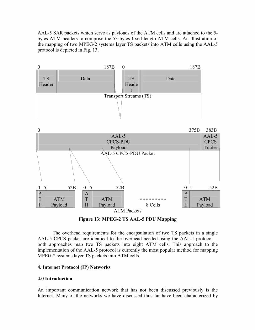
AAL-5 SAR packets which serve as payloads of the ATM cells and are attached to the 5-bytes ATM headers to comprise the 53-bytes fixed-length ATM cells. An illustration of the mapping of two MPEG-2 systems layer TS packets into ATM cells using the AAL-5 protocol is depicted in Fig. 13. 0 187B 0 187B
TS
Header
Data
TS
Header
Data
Transport Streams (TS) 0 375B 383B
AAL-5 CPCS-PDU
Payload
AAL-5 CPCS Trailer
AAL-5 CPCS-PDU Packet 0 5 52B 0 5 52B 0 5 52B ATH
ATM
Payload
A TH
ATM
Payload
� � � � � � � � �
8 Cells
A TH
ATM
Payload ATM Packets
Figure 13: MPEG-2 TS AAL-5 PDU Mapping The overhead requirements for the encapsulation of two TS packets in a single AAL-5 CPCS packet are identical to the overhead needed using the AAL-1 protocol�both approaches map two TS packets into eight ATM cells. This approach to the implementation of the AAL-5 protocol is currently the most popular method for mapping MPEG-2 systems layer TS packets into ATM cells. 4. Internet Protocol (IP) Networks 4.0 Introduction An important communication network that has not been discussed previously is the Internet. Many of the networks we have discussed thus far have been characterized by

physical layer medium and protocols. The Internet, on the other hand, allows for communication across various networks having different physical medium and lower-layer protocols. Communication among these separate networks is facilitated by abstracting the lower layer protocols using a common network protocol known as the Internet Protocol (IP). The most commonly used network protocol today is the IPv4 protocol. The IPv4 header consists of a 20-byte fixed header followed by an optional variable length header. Among the fixed header fields are the version, header length, type of service, packet length, identification and fragmentation information, time to live, transport protocol, header checksum, source and destination addresses.
Popularity of the Internet and forecasts of future applications of the Internet have increased rapidly. Particularly, the convergence of communications, computing, and entertainment has begun. It is likely that in the not so distant future separate applications such as telephony, televisions, and the web will merge into flexible computing systems. We envision that future stationary and mobile telephone and television devices throughout the world will become Internet nodes used for audio and video communications. To accommodate the large number of new nodes on the Internet, a new version of the IP protocol had to emerge. Currently, we are in the midst of a migration to a new network protocol�IPv6.31
In 1990, IETF had begun work on the new IP protocol. Its aim was to provide sufficient addresses to accommodate future growth of the Internet and increase the protocol�s efficiency and flexibility. The main difference introduced in IPv6 is longer addresses. The new IPv6 addresses are 16-bytes long; whereas, the old IPv4 addresses consist of merely 4-bytes. Additionally, the header of the IPv6 protocol is much simpler and more flexible than its predecessor. Reduced number of fields and improved optional field support has resulted in faster router processing time. Moreover, network security has been improved by incorporation of authentication and privacy features.32 Finally, the quality-of-service attributes were enhanced in the new protocol. The fields of the IPv6 header consist of the version, traffic class, flow label, payload length, next header, hop limit, source and destination addresses.
Audio Video Control
SIP SAP SDP
RSVP RTP RTCP RTSP
UDP TCP
31 The IPv5 denotes an experimental real-time stream protocol that was not widely used. 32 The security features of IPv6 have been incorporated into the IPv4 protocol.

IP
Data Link
Physical
Figure 14: Video Internet Protocol Stack An illustration of the protocol stack used for video communication over the Internet is depicted in Fig. 14. The primary transport layer protocols used over the Internet are the User Datagram Protocol (UDP) and Transport Control Protocol (TCP). The UDP is an unreliable connectionless protocol. It is well suited for real-time applications such as audio and video communications that require prompt delivery rather than accurate delivery and flow control. The UDP is restricted to an 8-byte header that contains minimal overhead including the source and destination ports, the length of the packet, and an optional checksum over the entire packet. The TCP is a far better known protocol for communication over the Internet. It is a reliable connection-oriented protocol and is used for most current applications used over the Internet. Among the most popular applications are remote login, electronic mail, file transfer, hypertext transfer, etc. These applications require precise delivery rather than timely delivery of the contents. TCP uses sequencing for packet reordering and an acknowledgement and retransmission process�known as Automatic Retransmission Request (ARQ)�for packet recovery. It also relies on a complex flow control scheme to avoid packet congestion. TCP packets have at a minimum a 20-byte header and contain numerous fields including source and destination ports, sequence and acknowledgement numbers, header length, various flags, window size, checksum, urgent pointer, and optional fields. In this section, an overview of the protocols used for video communications over the Internet is presented. A discussion of the multicast backbone (MBONE) is provided in Section 4.1. The standard protocol for the transport of real-time data�Real-time Transport Protocol (RTP)�is presented in Section 4.2. Augmented to the RTP is the standard protocol for data delivery monitoring, as well as minimal control and identification capability, provided by the Real-time Transport Control Protocol (RTCP) which presented in Section 4.3. An application level protocol for the on-demand control over the delivery of real-time data is provided by the Real Time Streaming Protocol (RTSP) discussed in Section 4.4. A protocol stack architecture designed as an Internet telephony standard known as H.323 is described in Section 4.5. A more flexible approach to real-time communications over the Internet has been proposed by the Session Initiation Protocol (SIP) which is presented in Section 4.6. Integrated services architecture and the basic methods used for resource reservation and quality-of-service control is provided by the Resource Reservation Protocol (RSVP) which is discussed in Section 4.7. A simpler approach to quality-of-service control provided by the differentiated services architecture and the operation of the DiffServ protocol is presented in Section 4.8. For brevity, the

protocols discussed in this section will be illustrated by concentrating primarily on MPEG-2 video communications over the Internet. 4.1 Multicast Backbone (MBONE) A critical factor in our ability to provide worldwide multimedia communication is the expansion of the existing bandwidth of the Internet. The NSF has recently restructured its data networking architecture by providing the very-high-speed Backbone Network Service (vBNS). The vBNS currently employs ATM switches and OC-12c SONET fiber optic communications at data rates of 622 Mbps.
The vBNS Multicast Backbone (MBONE)�a worldwide digital radio and television service on the Internet�was developed in 1992. MBONE is used to provide global digital multicast real-time audio and video broadcast via the Internet. The multicast process is intended to reduce the bandwidth consumption of the Internet.
Let us consider the broadcast of a television station over the Internet. It is apparent that standard Internet technology would require a separate transmission of the television signal between the station and each television receiver. The amount of bandwidth required by such an approach to global television broadcast would be impossible to accommodate. Tremendous bandwidth losses are incurred by the transmission of multiple copies of the television signal over large segments of the communication network that are shared by multiple users. The aim of MBONE is to propagate a single packet stream over routing path segments that are shared by multiple users. Specifically, packet streams are addressed to user groups and multiple copies generated only in nodes where the routing path is no longer common to all members of the user group. Implementation of MBONE is through a virtual overlay network on top of the Internet. It consists of islands that support multicast traffic and tunnels that are used to propagate MBONE packets between these islands. The islands are interconnected using mrouters (multicast routers) which are logically connected by tunnels.
The Multicast Internet Protocol (Multicast IP) was adopted as the standard protocol for multicast applications on the Internet. MBONE packets are transmitted as multicast IP packets between mrouters in different islands. Multicast IP packets are encapsulated within ordinary IP packets and regarded as standard unicast data by ordinary routers along a tunnel. Operation of MBONE is facilitated by using multicast addresses.33 This address serves the role of a station frequency in traditional radio broadcasts or channel number in television transmission. Identification of the multicast addresses that will be broadcasted is established by using the Internet Group Management Protocol (IGMP). Periodically, IGMP broadcast packets are sent by each mrouter to determine which hosts would like to receive which multicast addresses. IGMP responses are sent back by the hosts indicating the multicast addresses they wish to receive.
The routing process used by MBONE is the reverse path forwarding routing algorithm which helps prevent flooding. In order to limit the scope of multicasting, a weight is used in the Time to Live field of the IP header. The weight assigned to a packet is determined by the source and its value is decremented by the weight of each tunnel it passes. Once the weight of a packet is no longer sufficient to path through a tunnel, the
33 A multicast address is a class D address provided to the source.

packet is discarded. Consequently, the region of broadcasting may be limited by adjusting the weight of the transmitted packets. MBONE applications such as multimedia data broadcasting do not require reliable communication or flow control. These applications do require, however, real-time transmission over the Internet. The loss of an audio or video packet will not necessarily degrade the broadcast quality. Significant jitter delay, on the other hand, cannot be tolerated. The user datagram protocol (UDP)�not the transmission control protocol (TCP)�is consequently used for transmission of multimedia traffic. 4.2 Real-time Transport Protocol (RTP) The real-time transport protocol (RTP) provides end-to-end network transport functions for the transmission of real-time data such as audio or video over unicast or multicast services independent of the underlying network or transport protocols. Its functionality, however, is enhanced when run on top of the user datagram protocol (UDP). It is also assumed that resource reservation and quality of service (QoS) have been provided by lower layer services (e.g., RSVP). The RTP protocol, however, does not assume nor provide guaranteed delivery or packet order preservation. RTP services include timestamp packet labeling for media stream synchronization, sequence numbering for packet loss detection, and packet source identification and tracing. RTP is designed to be a flexible protocol that can be used to accommodate the detailed information required by particular applications. The RTP protocol is, therefore, deliberately incomplete and its full specification requires one or more companion documents: profile specification and payload format specification. The profile specification document defines a set of payload types and their mapping to payload formats. The payload format specification document defines the method by which particular payloads are carried. The RTP protocol supports the use of intermediate system relays known as translators and mixers. Translators convert each incoming data stream from different sources separately. An example of a translator is used to provide access to an incoming audio or video packet stream beyond an application-level firewall. Mixers combine the incoming data streams from different sources to form a single stream. An example of a mixer is used to resynchronize an incoming audio or video packet stream from high-speed networks to a lower-bandwidth packet stream for communication across low-speed networks. An illustration of the RTP packet header is depicted in Fig. 15. A corresponding glossary of the RTP packet header is provided in Table 7. The version number of the RTP protocol is defined in the version (V) field. The version number of the current RTP protocol is number two.34 A padding (P) bit is used to indicate if additional padding bytes, which are not part of the payload, have been appended at the end of the packet. The last byte of the padding field provides the length of the padding field. An extension (X) bit is used to indicate if the fixed header is followed by a header extension. The contributing source count (CC) provides the number (up to fifteen) of contributing source (CSRC) identifiers that follow the fixed header. A marker (M) bit is defined by a profile
34 Version numbers 0 and 1 have been used in previous versions of the RTP protocol.

for various applications such as the marking of frame boundaries in the packet stream. The payload type (PT) field provides the format and interpretation of the payload. The mapping of the PT code to payload formats is specified by a profile. An incremental sequence number (SN) is used by the receiver to detect packet loss and restore packet sequence. The initial value of the SN is random in order to combat possible attacks on encryption. The timestamp (TS) provides the sampling instant of the first byte in the packet derived from a monotonically and linearly incrementing clock for synchronization and jitter delay estimation. The clock frequency is indicated by the profile or payload format specification. The initial value of the timestamp is once again random. The synchronization source (SSRC) field is used to identify the source of a stream of packets from a synchronization source. A translator forwards the stream of packets while preserving the SSRC identifier. A mixer, on the other hand, becomes the new synchronization source and must therefore include its own SSRC identifier. The SSRC field is chosen randomly in order to prevent two synchronization sources from having the same SSRC identifier in the same session. A detection and collision resolution algorithm prevents the possibility that multiple sources will select the same identifier. The contributing source (CSRC) field designates the source of a stream of packets that has contributed to the combined stream, produced by a mixer, in the payload of this packet. The CSRC identifiers are inserted by the mixer and correspond to the SSRC identifiers of the contributing sources. As indicated earlier, the CC field provides the number (up to fifteen) of contributing sources. 0 15 31b V=2
P
X
CC
M
PT
SN
Timestamp (TS)
Synchronization Source Identifier (SSRC)
Contributing Source Identifier 1 (CSRC)
• • •
Contributing Source Identifier N (CSRC)
Figure 15: RTP Packet Header

Abbr Function V Version P Padding X Extension
CC Contibuting Source Count M Marker PT Payload Type SN Sequence Number TS Time-Stamp
SSRC Synchronization Source Identifier CSRC Contributing Source Identifier
Table 7: RTP Packet Header Glossary The quality of real-time multimedia transmission in noisy environments is very poor due to high packet loss rates. This problem can be alleviated by the use of generic forward error correction (FEC) to compensate for packet loss of arbitrary real-time media streams supported by a wide variety of error-correction codes (e.g., Parity, Reed-Solomon, and Hamming codes). The payload of an FEC packet provides parity blocks obtained by exclusive-or based operations on the payloads and some header fields of several RTP media packets. The FEC packets and media packets are encapsulated and sent as separate RTP streams. This feature implies that FEC is backward compatible with hosts that do not support and simply ignore RTP FEC streams. The RTP packet header used for the RTP encapsulation of FEC determines the payload type (PT) field through dynamic out of band means. The sequence number (SN) field is set from an independent sequence number space�consecutive FEC packets are assigned incremental SNs. The timestamp (TS) field is monotonically increasing and corresponds to the value of the media RTP timestamp at the time that the FEC packet is sent. The source synchronization (SSRC) field is generally identical to the corresponding field in the RTP media stream. The contributing source (CSRC) field, on the other hand, is omitted. The remaining fields are computed via the protection operation of the FEC.
The RTP encapsulation of FEC requires the use of the RTP FEC header extension following the RTP packet header. The RTP FEC header extension contains the sequence number base (SNB) field, which should be set to the minimum sequence number of the packets protected by FEC. The FEC may extend over any string that does not exceed 24 packets. The length recovery (LR) field is used to determine the length of any recovered packets. This is accomplished by applying the protection operation to the lengths of the media payloads associated with the FEC packet. An extension (E) bit must currently be set to zero and is reserved for future use of a header extension. The payload type recovery (PTR) field is used to ascertain the payload type of any recovered packets. This is obtained by applying the protection operation to the payload type fields of the media packet headers associated with the FEC. The mask (M) is a 24-bit field that provides the string of packets that are associated with the FEC. The activation of the n-th bit in the mask (M) field is used to indicate that the media packet whose sequence number (SN)

corresponds to (SNB + n - 1) is associated with the FEC. The timestamp recovery (TS) field is used to resolve the timestamps of any recovered packets. This field is computed by applying the protection operation to the timestamp fields of the media packet headers associated with the FEC. An illustration of the RTP generic FEC header is depicted in Fig. 16. A corresponding glossary of the generic FEC header is provided in Table 8. 0 15 31b
SNB
LR
E
PTR
M
TR
Figure 16: RTP FEC Header Extension
Abbr Function SNB Sequence Number Base LR Length Recovery E Extension
PTR Payload Type Recovery M Mask TR Timestamp Recovery
Table 8: RTP FEC Header Extension Glossary The JPEG standard is used for the compression of continuous-tone still images. A direct extension of the JPEG standard to video compression known as Motion JPEG (MJPEG) is obtained by the JPEG encoding of each individual picture in a video sequence. The RTP payload encapsulation of MJPEG data streams is restricted to the single-scan interleaved sequential DCT operating mode represented in abbreviated format. The RTP header for encapsulation of MJPEG is set using a 90 KHz timestamp. The RTP marker (M) bit must be activated in the last packet of each frame.
The RTP payload encapsulation of MJPEG format requires that an RTP MJPEG header follow each RTP packet header. The RTP MJPEG header represents all of the information that is associated with the JPEG frame headers and scan headers. The RTP MJPEG header contains a type specific (TS) field whose interpretation depends on the value of the type (T) field. The fragment offset (FO) field provides the number of bytes that the current packet is offset in the JPEG frame data. The total length of the JPEG

frame data�corresponding to the FO field and the length of the payload data in the current packet�must not exceed 2^24 bytes. The type (T) field specifies information included in the JPEG abbreviated table-specification as well as other parameters not defined by JPEG. Types 0�63 are reserved for fixed well-known mappings. Types 64�127 are also reserved for fixed well-known mappings that contain restart markers in the JPEG data. For these types, a restart marker header must appear immediately following the RTP MJPEG header. Types 128�255 are reserved for dynamic mappings defined by a session setup protocol. The quantization tables (Q) field defines the quantization tables for the frame. Q values 0�127 indicate that the type (T) field determines the quantization tables. Q values 128�255 indicate that a quantization table header following the RTP MJPEG header and possible restart marker header is used to explicitly specify the quantization tables. The width (W) and height (H) fields provide the width and height of the image in 8-pixel multiples, respectively. The maximal width and height of the image is restricted to 2040 pixels.35 Depending on the values of the T and Q fields, the restart marker header and quantization table header may follow the RTP MJPEG header. An illustration and a corresponding glossary of the RTP MJPEG header are provided in Fig. 17 and Table 9, respectively. 0 15 31b
TS
FO
T
Q
W
H
Figure 17: RTP MJPEG Header
Abbr Function TS Type Specific FO Fragment Offset T Type Q Quantization Tables W Width H Height
Table 9: RTP MJPEG Header Glossary
35 The height (H) field represents the height of a video field in the interlaced mode of motion JPEG.

The RTP payload encapsulation of MJPEG format fragments the data stream into packets such that each packet contains an entropy-coded segment of a single-scan frame. The payload is started immediately with the entropy-coded scan�the scan header is not present�and terminated explicitly or implicitly with an EOI marker.
The most popular current video compression standards are based on MPEG. RTP payload encapsulation of MPEG data streams can be accomplished in one of two formats: Systems stream (SS)�transport stream (TS) and program stream (PS)�as well as elementary stream (ES). The format used for encapsulation of MPEG SS is designed for maximum interoperability with video communication network environments. The format used for the encapsulation of MPEG SS, however, provides greater compatibility with the Internet architecture including other RTP encapsulated media streams and current efforts in conference control.36
The RTP header for encapsulation of MPEG SS is set as follows: The payload type (PT) field should be assigned to correspond to the systems stream format in accordance with the RTP profile for audio and video conferences with minimal control [X]. The marker (M) bit is activated whenever the timestamp is discontinuous. The timestamp (TS) field provides the target transmission time of the first byte in the packet derived from a 90 KHz clock reference, which is synchronized to the system stream program clock reference (PCR) or system clock reference (SCR). This timestamp is used to minimize network jitter delay and synchronize relative time drift between the sender and receiver. The RTP payload must contain an integral number of MPEG-2 TS packets�there are no restrictions imposed on MPEG-1 SS or MPEG-2 PS packets.
The RTP header for encapsulation of MPEG ES is set as follows: The payload type (PT) field should once again be assigned to correspond to the elementary stream format in accordance with the RTP profile for audio and video conferences with minimal control [X]. The marker (M) bit is activated whenever the RTP packet contains an MPEG frame end code. The timestamp (TS) field provides the presentation time of the subsequent MPEG picture derived from a 90 KHz clock reference, which is synchronized to the system stream program clock reference (PCR) or system clock reference (SCR). The RTP payload encapsulation of MPEG ES format requires that an MPEG ES video-specific header follow each RTP packet header. The MPEG ES video-specific header contains a must be zero (MBZ) field that is currently unused and must be set to zero. An indicator (T) bit is used to announce the presence of an MPEG-2 ES video-specific header extension following the MPEG ES video-specific header. The temporal reference (TR) field provides the temporal position of the current picture within the current group of pictures (GOP). The active N (AN) bit is used for error resilience and is activated when the following indicator (N) bit is active. The new picture header (N) bit is used to indicate parameter changes in the picture header information for MPEG-2 payloads.37 A sequence header present (S) bit indicates the occurrence of an MPEG sequence header. A beginning of slice (B) bit indicates the presence of a slice start code at the beginning of the packet payload, possibly preceded by any combination of a video sequence header, group of pictures (GOP) header, and picture header. An end of slice (E) bit indicates that the last byte of the packet payload is the end of a slice. The picture type
36 RTP payload encapsulation of MPEG elementary stream (ES) format defers some of the issues addressed by the MPEG systems stream (SS) to other protocols proposed by the Internet community. 37 The active N (AN) and new picture header (N) indicator bits must be set to 0 for MPEG-1 payloads.

(PT) field specifies the picture type�I-Picture, P-Picture, B-Picture, or D-Picture. The full pel backward vector (FBV), backward f code (BFC), full pel forward vector (FFV), and forward f code (FFC) fields are used to provide information necessary for determination of the motion vectors.38 Figure 18 and Table 10 provide an illustration and corresponding glossary of the RTP MPEG ES video-specific header, respectively. 0 15 31b
MBZ
T
TR
AN
N
S
B
E
P
FBV
BFC
FFV
FFC
Figure 18: RTP MPEG ES Video-Specific Header
Abbr Function MBZ Must Be Zero
T Video-Specific Header Extension TR Temporal Reference AN Active N N New Picture Header S Sequence Header Present B Beginning of Slice E End of Slice P Picture Type
FBV Full Pel Backward Vector BFC Backward F Code FFV Full Pel Forward Vector FFC Forward F Code
Table 10: RTP MPEG ES Video-Specific Header Glossary
An illustration of the RTP MPEG-2 ES video-specific header extension is depicted in Fig. 19. A corresponding glossary used to summarize the function of the RTP MPEG-2 ES video-specific header extension is provided in Table 11. Particular attention should be paid to the composite display flag (D) bit, which indicates the presence of a composite display extension�a 32-bit extension that consists of 12 zeroes followed by 20 bits of composite display information�following the MPEG-2 ES video-specific header extension. The extension (E) bit is used to indicate the presence of one or more optional extensions�quantization matrix extension, picture display extension, picture temporal scalable extension, picture spatial scalable extension, and copyright extension�following the MPEG-2 ES video-specific header extension as well as the composite display extension. The first byte of each of these extensions is a length (L) field that 38 Only the FFV and FFC fields are used for P-Pictures; whereas, none of these fields are used for I-Pictures and D-Pictures.

provides the number of 32-bit words used for the extension. The extensions are self-identifying since they must also include the extension start code (ESC) and the extension start code ID (ESCID). For additional information regarding the remaining fields in the MPEG-2 ES video-specific header extension refer to [X].
0 15 31b X
E
F[00]
F[01]
F[10]
F[11]
DC
PS
T
P
C
Q
V
A
R
H
G
D
Figure 19: RTP MPEG-2 ES Video-Specific Header Extension
Abbr Function X Unused (Zero) E Extension
F[00] Forward Horizontal F Code F[01] Forward Vertical F Code F[10] Backward Horizontal F Code F[11] Backward Vertical F Code DC Intra DC Precision (Intra Macroblock DC difference Value) PS Picture Structure (Field / Frame) T Top Field First (Odd / Even Lines First) P Frame Predicted Frame DCT C Concealment Motion Vectors (I-Picture Exit) Q Q-Scale Type (Quantization Table) V Intra VLC Format (Huffman Code) A Alternate Scan (Section / Interlaced Field Breakup) R Repeat First Field H Chroma 420 Type (Options also include 422 and 444) G Progressive Frame D Composite Display Flag
Table 11: RTP MPEG-2 ES Video-Specific Header Extension Glossary The RTP payload encapsulation of MPEG ES format fragments the stream into packets such that the following headers must appear hierarchically at the beginning of a single payload of an RTP packet: MPEG video sequence header, MPEG GOP header, and MPEG picture header. The beginning of a slice�the fundamental unit of recovery�must be the first data (not including any MPEG ES headers) or must follow an integral number of slices in the payload of an RTP packet.

4.3 Real-time Transport Control Protocol (RTCP) The real-time transport control protocol (RTCP) augments the RTP protocol to monitor the quality of service (QoS) and data delivery monitoring as well as provide minimal control and identification capability over unicast or multicast services independent of the underlying network or transport protocols. The primary function of the RTCP protocol is to provide feedback on the quality of data distribution that can be used for flow and congestion control. The RTCP protocol is also used for the transmission of a persistent source identifier to monitor the participants and associate related multiple data streams from a particular participant. The RTCP packets are sent to all participants in order to estimate the rate at which control packets are sent. An optional function of the RTCP protocol can be used to convey minimal session control information. The implementation of the RTCP protocol is based on the periodic transmission to all participants in the session of control information in several packet types summarized in Table 12. The sender report (SR) and receiver report (RR) provide reception quality feedback and are identical except for the additional sender information that is included for use by active senders. The SR or RR packets are issued depending on whether a site has sent any data packets during the interval since the last two reports were issued. The source description item (SDES) includes items such as canonical end-point identifier (CNAME), user name (NAME), electronic mail address (EMAIL), phone number (PHONE), geographic user location (LOC), application or tool name (TOOL), notice/status (NOTE), and private extensions (PRIV). The end of participation (BYE) packet indicates that a source is no longer active. The application specific functions (APP) packet is intended for experimental use as new applications and features are developed.
Abbr Function SR Sender Report RR Receiver Report
SDES Source Description Item (e.g., CNAME) BYE End of Participation Indication APP Application Specific Functions
Table 12: RTCP Packet Types RTCP packets are composed of an integral number of 32-bit structures and are, therefore, stackable�multiple RTCP packets may be concatenated to form compound RTCP packets. RTCP packets must be sent in compound packets containing at least two individual packets of which the first packet must always be a report packet. Should the number of sources for which reports are generated exceed 31�the maximal number of sources that can be accommodated in a single report packet�additional RR packets must follow the original report packet. An SDES packet containing a CNAME item must also be included in each compound packet. Other RTCP packets may be included subject to

bandwidth constraints and application requirements in any order, except that BYE packet should be the last packet sent in a given session. These compound RTCP packets are forwarded to the payload of a single packet of a lower layer protocol (e.g., UDP). An illustration of the RTCP SR and RR packets is depicted in Fig. 20 and 21, respectively. A corresponding glossary of the RTCP SR and RR packets is provided in Table 13. The RTCP SR and RR packets are composed of a header section, zero or more reception report blocks, and a possible profile-specific extension section. The SR packets also contain an additional sender information section. The header section defines the version number of the RTCP protocol in the version (V) field. The version number of the current RTCP protocol is number two�the same as the version number of the RTP protocol. A padding (P) bit is used to indicate if additional padding bytes, which are not part of the control information, have been appended at the end of the packet. The last byte of the padding field provides the length of the padding field. In a compound RTCP packet, padding should only be required on the last individual packet. The reception report count (RC) field provides the number of reception report blocks contained in the packet. The packet type (PT) field contains the constant 200 and 201 to identify the packet as a sender report (SR) and receiver report (RR) RTCP packet, respectively. The length (L) field provides the number of 32-bit words of the entire RTCP packet�including the header and possible padding�minus one. The synchronization source (SSRC) field is used to identify the sender of the report packet.
The sender information section appears in the sender report (SR) packet exclusively and provides a summary of the data transmission from the sender. The network time protocol timestamp (NTPT) indicates the wallclock time at that instant the report was sent.39 This timestamp along with the timestamps generated by other reports is used to measure the round-trip propagation to the other receivers. The real-time protocol timestamp (RTPT) corresponds to the NTPT provided using the units and random offset used in the RTP data packets. This correspondence can be used for synchronization among sources whose NTP timestamps are synchronized. The packet count (PC) field indicates the total number of RTP data packets transmitted by the sender since the beginning of the session up until the generation of the SR packet. The octet count (OC) field represents the total number of bytes in the payload of the RTP data packets�excluding header and padding�transmitted by the sender since the beginning of the session up until the generation of the SR packet. This information can be used to estimate the average payload data rate.
All RTCP report packets must contain zero or more reception report blocks corresponding to the number of synchronization sources from which the receiver has received RTP data packets since the last report. These reception report blocks convey statistical data pertaining to the RTP data packets received from a particular synchronization source. The synchronization source (SSRC-N) field is used to identify the N-th synchronization source to which the statistical data in the N-th reception report block is attributed. The fraction lost (FL) field indicates the fraction of RTP data packets from the N-th synchronization source lost since the previous report was sent. This fraction is defined as the number of packets lost divided by the number of packets
39 Wallclock time (absolute time) represented using the Network Time Protocol (NTP) timestamp format is a 64-bit unsigned fixed-point number provided in seconds relative to 0h UTC on January 1, 1900.

expected (NPE). The cumulative number of packets lost (CNPL) field provides the total number of RTP data packets from the N-th synchronization source lost since the beginning of the session. The CNPL is defined as the number of packets expected (NPE) less the number of packets received. The extended highest sequence number received (EHSNR) field contains the highest sequence number of the RTP data packets received from the N-th synchronization source stored in the 16 least significant bits of the EHSNR field. Whereas, the extension of the sequence number provided by the corresponding count of sequence number cycles is maintained and stored in the 16 most significant bits of the EHSNR field. The EHSNR is also used to estimate the number of packets expected (NPE) which is defined as the last EHSNR less the initial sequence number received. The interarrival jitter (J) field provides an estimate of the statistical variance of the interarrival time of the RTP data packets from the N-th synchronization source. The interarrival jitter (J) is defined as the mean deviation of the interarrival time D between the packet spacing at the receiver compared to the sender for a pair of packets; i.e., D(i,j) = (R(j) - R(i)) - (S(j) � S(i)), where S(i) and R(i) are used to denote the RTP timestamp from the RTP data packet i and the time of arrival in RTP timestamp units of RTP data packet i, respectively. The interarrival time D is equivalent to the difference in relative transit time for the two packets; i.e., D(i,j) = (R(j) - S(j)) - (R(i) � S(i)). An estimate of the interarrival jitter (J) is obtained by the first-order approximation of the mean deviation given by
The estimate of the interarrival jitter (J) is computed continuously as each RTP data packet is received from the N-th synchronization source and sampled whenever a report is issued. The last sender report timestamp (LSR) field provides the NPT timestamp (NTPT) received in the most recent RTCP sender report (SR) packet that arrived from the N-th synchronization source. The LSR field is confined to the middle 32 bits out of the 64-bit NTP timestamp (NTPT). The delay since last sender report (DLSR) expresses the delay between the time of the reception of the most recent RTCP sender report (SR) packet that arrived from the N-th synchronization source and sending the current reception report block. These measures can be used by the N-th synchronization source to estimate the round-trip propagation delay (RTPD) between the sender and the N-th synchronization source. The estimate of the RTPD obtained provided the time of arrival T of the reception report block from the sender is recorded at the N-th synchronization source is given by RTPD = T � LSR � DLSR. 0 15 31b V=2
P
RC
M
PT=200
L
SSRC
)|)1,D((|161 JiiJJ −−+=

NTPT � NTP Timestamp (Most Significant Word)
NTPT - NTP Timestamp (Least Significant Word)
RTPT - RTP Timestamp
PC
OC
SSRC-1
FL
CNPL
EHSNR
J
LSR
DLSR
SSRC-2
• • •
Profile-Specific Extensions
Figure 20: RTCP Sender Report (SR) Packet

0 15 31b V=2
P
RC
M
PT=201
L
SSRC
SSRC-1
FL
CNPL
EHSNR
J
LSR
DLSR
SSRC-2
• • •
Profile-Specific Extensions
Figure 21: RTCP Receiver Report (RR) Packet

Abbr Function V Version P Padding
RC Reception Report Count PT Packet Type L Length
SSRC Synchronization Source Identifier (Sender) NTPT Netowrk Time Protocol Timestamp RTPT Real-Time Transport Protocol Timestamp
PC Packet Count (Sender) OC Octet Count (Sender)
SSRC-N Synchronization Source Identifier-N FL Fraction Lost
CNPL Cumulative Number of Packets Lost EHSNR Extended Highest Sequence Number Received
J Interarrival Jitter LSR Last Sender Report Timestamp
DLSR Delay Since Last Sender Report Timestamp
Table 13: RTCP Sender Report (SR) and Receiver Report (RR) Packet Glossary Figure 22 and Table 14 provide an illustration and a corresponding glossary of the RTCP SDES packet. The SDES packet is composed of a header followed by zero or more chunks. The SDES packet header version (V), padding (P), and length (L) are used in the same manner as described for the previous RTCP packets. The packet type (PT) contains the constant 202 to identify the packet as an RTCP SDES packet. The source count (SC) provides the number of chunks contained in this SDES packet. Each chunk consists of a synchronization source (SSRC)/contributing source (CSRC) identifier followed by zero or more items.

0 15 31b
V=2
P
SC
PT=SDES=202
L
SSRC/CSRC
SDES Item
Figure 22: RTCP Source Description (SDES) Packet
Abbr Function V=2 Version
P Padding SC Source Count PT Packet Type L Length
SSRC/CSRC Synchronization Source/Contributing Source Identifier SDES Item Source Description Item
Table 14: RTCP Source Description (SDES) Packet Glossary
Figure 23 and Table 15 provide an illustration and a corresponding glossary of the RTCP SDES CNAME item. The CNAME field contains the constant 1 to identify this as an RTCP SDES CNAME packet. The length (L) describes the length of the text field in the user and domain name (UDN) field. The UDN text field is restricted to be no longer than 255 bytes. The format used for the UDN field�"user@host� or �host� if a user is not available�should be derived algorithmically, when possible. 0 15 31b
CNAME=1
L
UDN
Figure 23: RTCP SDES Canonical End-Point Identifier (CNAME) Item
Abbr Function CNAME SDES Item Type
L Length UDN User and Domain Name
Table 15: RTCP SDES Canonical End-Point Identifier (CNAME) Item Glossary

4.4 Real-time Transport Streaming Protocol (RTSP) The real-time streaming protocol (RTSP) is an application level protocol that provides for the on-demand control over the delivery of real-time data. The RTSP protocol is intended for the control of channels and mechanisms used for multiple synchronized data delivery sessions from stored and live sources such as audio and video streams between media servers and clients. Functionally, the RTSP protocol serves the role of a �remote control� of multimedia communication systems�networks and servers. The RTSP protocol relies on a presentation description to define the set of streams that it controls. These controls support for the following basic operations: (a) retrieval of media from a media server, (b) invitation of a media server to a conference, and (c) addition of media to an existing presentation. Table 16 provides a summary of the methods used by the RTSP protocol to perform various operations on the presentation or media streams.40
Abbreviation Function OPTIONS Client and server inform each other of nonstandard options
DESCRIBE Retrieves the description of a presentation or media object
ANNOUNCE (a) Client to Server: Posts the description of a presentation or media object (b) Server to Client: Updates the session description in real-time
SETUP Specifies the transport mechanism to be used for streamed media
PLAY Instructs server to start sending data via the transport mechanism
PAUSE Temporarily interrupts stream delivery TEARDOWN Stops the stream delivery
GET_PARAMETER Retrieves the value of a parameter of a presentation or stream SET_PARAMETER Sets the value of a parameter of a presentation or stream
REDIRECT Informs the client that it must connect to another server location RECORD Initiates recording a range of media data
Table 16: RTSP Methods Presentation description of sessions in RTSP uses the Session Description
Protocol (SDP). The SDP is a generic textual method for describing the presentation details. It includes the session�s name and purpose, streams� transport and media types, and presentations� start and end times.
Control requests and responses using RTSP may be sent over TCP or UDP. The order of arrival of the requests is critical. Therefore, the request header has a Cseq field that contains the sequence numbers of the clients� requests. A retransmission mechanism is required in case any requests are lost. The use of UDP is thus limited and may cause severe problems. 40 The RTSP protocol is intentionally similar in syntax and operation to HTTP 1.1�RTSP aims to provide the same services to audio and video streams as HTTP does for text and graphics.

Another problem in the use of RTSP is the absence of a mechanism for system recovery. For example, once the client has lost state information about a session, there is no method to send control requests to the server. A presentation stream may continue to be transmitted to the client unless the session identifier can be recovered. Thus, RTSP implementation requires some other failsafe method or session control option. 4.5 H.323 In 1996, the ITU presented the H.323 protocol stack in an effort to adopt a standard communication protocol stack for visual telephony over communication networks. The H.323 standard provides an architecture for the design of Internet telephony. It is based on the integration of various protocols to support functionality such as speech and video compression, call signaling and control, real-time transport, etc. The H.323 protocol stack, however, does not provide a quality-of-service (QoS) capability. An illustration of the H.323 protocol stack is depicted in Fig. 24.
Video Speech Control
H.261 G.711
RTP
RTCP H.225 (RAS)
Q.391 (Call
Signaling)
H.245 (Call
Control)
UDP TCP
IP
Data Link Protocol
Physical Layer Protocol
Figure 24: H.323 Protocol Stack. The H.323 protocol stack relies on the H.26x standards for video compression;41 similarly, it uses the G.71x and G.72x standards for speech compression.42 The H.245
41 The H.323 protocol stack must support the H.261 video compression standard with a spatial resolution of QCIF. H.261 provides video compression based on the Discrete Cosine Transform (DCT) representation. Raw video representation of QCIF and CIF formats require uncompressed data rates of 9.1 and 37 Mbps. H.261 video representation of QCIF and CIF streams are compressed to 64 and 384 Kbps, respectively. Modern systems that use the H.323 standard use H.263 for video communications.

call control protocol is adopted in order to allow terminals to negotiate the compression standards and bandwidth they desire. The Q.931 call signaling protocol is used to perform standard telephony functions such as establish and terminate connections, control dial tones and ringing, etc. The registration/admission/status (RAS) protocol allows the terminals to communicate to a gatekeeper in a local area network. The RTP protocol is used for data transport and is managed by the RTCP protocol. RTCP is also used for audio/video synchronization.
Abbreviation Function SETUP PC request sent to the telephone
CALL PROCEEDING Gatekeeper response sent to the PC ALERT End office response sent to the PC
CONNECT End office response sent to the PC Table 17: Q.931 call setup messages.
To illustrate the operation of the H.323 protocol we shall describe a sequence of messages needed to establish communication when a PC is used to call a telephone. Call setup in the H.323 protocol stack relies on existing telephone network protocols. These protocols are connection-oriented; hence, a TCP connection is required for call setup. Table 17 summarizes some of the messages used by the Q.931 call signaling protocol. The PC sends a SETUP message to the gatekeeper over the TCP connection.43 The gatekeeper responds with a CALL PROCEEDING message to acknowledge receipt of the request. The SETUP message is forwarded by the gatekeeper to the gateway. The gateway contacts the end office associated with the terminal destination. The end office rings the telephone at the terminal destination and sends an ALERT message to the calling PC to inform it that ringing has begun. Once the telephone at the terminal destination has been connected, the end office send a CONNECT message to the calling PC to signal that connection has been established. Once connection has been established, the PC and gateway communicate directly, bypassing the gatekeeper in the calling PC�s LAN. When wither the PC or telephone hangs up, the Q.391 call signaling protocol is used to tear down the connection. 4.6 Session Initiation Protocol (SIP) The IETF proposed the session initiation protocol (SIP). Its aim was to design a simpler and more flexible method for real-time communication networks than H.323. Instead of
42 The H.323 protocol stack is required to be compatible with the G.711 speech compression standard. G.711 encodes a voice stream represented as an 8-bit Pulse Code Modulation (PCM) signal sampled at 8,000 samples per second yielding uncompressed speech at 64 Kbps. This is the standard currently used for digital transmission of telephone signals over the Public Switched Telephone Network (PSTN). Other speech compression standards such as G.722 and G.728 may also be used by the H.323 communication system. 43 Communication between the PC and the gatekeeper within the LAN has already been established prior to the call setup procedure. A gatekeeper discovery packet is broadcast over UDP to determine the gatekeeper�s IP address. The RAS protocol is used to send a sequence of messages over UDP in order to register the PC with the gatekeeper and request bandwidth.

an entire protocol stack required by H.323, SIP is a single protocol that is capable of interfacing with existing Internet protocols used for real-time communications. SIP can accommodate two-party, multi-party, and multicast sessions. The sessions may be used for audio, video, or data communications. The functionality of SIP is required to handle the setup and termination of sessions. It is also responsible for providing the services necessary for management of real-time communication sessions such as determining the callee�s location and capabilities.
Abbreviation Function INVITE Request initiation of a session
ACK Confirm initiation of a session BYE Request termination of a session
OPTIONS Query the capabilities of a host CANCEL Cancel a pending request
REGISTER Inform a redirection server of the current location of a user
Table 18: SIP Methods.
The SIP protocol is modeled after HTTP. A text message containing a method name and various parameters is sent. Table 18 lists the six methods defined by the core specification of SIP. A typical payload of SIP messages would be an SDP session description requested by the caller. Connection is established by a three-way handshake: An INVITE message is sent from the caller to the callee. The callee responds with an HTTP reply code. For example, if the callee accepts the call, it responds with a 200 reply code, indicating that the request succeeded. The session is connected once the caller responds to the callee with an ACK message to confirm receipt of the HTTP reply code. Termination may be initiated by a request from either the caller or callee by sending of a BYE message. The session has been terminated when receipt of the BYE message has been acknowledged.
Both UDP and TCP may be used for transport of SIP messages. Reliable transport of SIP messages is inherent when using TCP. In case UDP is used, SIP must provide its own reliability and retransmission mechanism. Nonetheless, SIP transmission over UDP allows for timing and reliability control that results in a superior signaling protocol. 4.7 Integrated Services � Resource Reservation Protocol (RSVP) Efforts at multimedia streaming over communication networks resulted in a Quality-of-Service (QoS) architecture known as integrated services. This architecture consists of a collection of flow-based algorithms aimed at both unicast and multicast applications. The main protocol proposed for integrated services architecture is the resource reservation protocol (RSVP).
The RSVP provides an integrated service resource reservation and QoS control. It supports dynamically changing unicast and multicast routing protocols in connectionless heterogeneous networks. An important example of the use of the RSVP protocol is the reservation of bandwidth in routers along the reserved path required to guarantee low

packet transfer times and minimal network jitter in multimedia applications such as audio and video communications over MBONE.
The RSVP protocol is based on receiver initiated reservation requests that are used to establish soft states in the routers along the reserved paths. Any receiver can send a reservation request up the spanning tree provided by a unicast or multicast routing algorithm to the sender. The routing algorithm used to generate the spanning tree is not part of the RSVP protocol. The reservation requests are propagated using the reversed path-forwarding algorithm along the spanning tree from the receiver towards the sender. Each router along the propagation path reserves the necessary bandwidth provided sufficient bandwidth is available. The reservation request will propagate all the way back along the spanning tree until it reaches the source or a node that already satisfies the reservation request. At this point the required bandwidth has been reserved along a path from the sender to the receiver. The senders and receivers must refresh the soft state in the routers along the reserved paths periodically to prevent the timing out of the reservation.
The reservation requests are propagated within the nodes�hosts and routers�to the local decision modules: admission control and policy control. The admission control module determines whether the node has the available resources to accommodate the reservation requested. The policy control module decides whether the receiver has the administrative permission to establish the reservation requested. The resource reservation requested is implemented, once approval from the local decision modules has been granted, by a collection of mechanisms known as traffic control: packet classifier and packet scheduler. The packet classifier determines the QoS class for each packet. The packet scheduler decides when each packet must be forwarded in order to achieve the guaranteed QoS. An illustration of the internal control mechanism of RSVP within the nodes is depicted in Fig. 25.
HOST ROUTER
Figure 25: RSVP in Hosts and Routers
Application
RSVP Process
Policy Control
Classifier
Packet Scheduler
Admis Control
RSVP Process
Policy Control
Admis ControlPacket
Scheduler
Classifier
Routing Process
RSVP
Data

There are two basic message types: RESV and PATH. The RESV messages are reservation requests that are sent by the hosts up the spanning tree provided by the routing protocol towards the sender. These messages create and maintain soft states in each node along the reserved paths. The reservation requests consist of a flow descriptor�a flowspec and a filter spec. The flowspec specifies the desired QoS (Rspec) and data flow (Tspec) parameters, for the packet scheduler. The filter spec defines the set of data packets (flow) that must receive the QoS specified by the flowspec, for the packet classifier.
The PATH messages are transmitted by the hosts down the spanning tree provided by the routing protocol�following the paths of the data flow�towards the receivers. These messages include the information necessary to route the RESV messages in the reverse direction (e.g., the IP address of the previous hop node). A PATH message must also provide a sender template�used to indicate the format of the data packets that will be transmitted by the sender�in the form of a filter spec. An additional parameter that must appear in these messages provides the traffic characteristics of the data flow that will be transmitted by the sender (sender Tspec). An optional package that carries advertising of the predicted end-to-end QoS (Adspec) is provided to the local traffic control, where it is updated and forwarded to other nodes down the spanning tree towards the receiver.44
Figure 26: RSVP Message Flow 44 RSVP supports an enhancement to the basic protocol, known as One Pass With Advertising (OPWA), for the prediction and distribution of end-to-end QoS.
RESV PATH
Sender 1 Sender 2
Receiver 1 Receiver 2

Figure 26 illustrates an example of the RSVP message flow. The sender initially generates PATH messages down the spanning tree provided by the routing protocol towards all possible receivers. Each receiver generates RESV messages propagated down the spanning tree, back along the reverse route than that followed by the PATH messages, towards the sender. The RESV messages will propagate all the way back along the spanning tree, provided sufficient resources are available, until it reaches the sender or a node that already satisfies the reservation request. In case sufficient resources are not available at a node, an error message is sent to the receiver and the procedure is aborted. The data packets are transmitted from the sender to the receivers along the same routes followed by the PATH messages. The senders and receivers generate RESV and PATH messages along the reserved paths periodically. Once these periodic messages have not been generated for a sufficiently long time duration or an explicit teardown instruction has been issued, the reserved path is cancelled. 4.8 Differentiated Services � DiffServ Integrated services present the potential to provide very high QoS for video communication network applications. However, the effort required in setting flow-based resource reservations along the route is enormous. Further, the control signaling required and state maintenance at routers limit the scalability of this approach. Consequently, at present, integrated services are rarely deployed for high QoS video communication networks. Differentiated services were proposed as a simpler approach to high QoS communication networks. The basic principle behind differentiated services is a class-based approach that relies on local routers. A set of service classes with corresponding forwarding rules is defined. A marker located in a field within the packet header is used to ascertain the level of service. Different levels of service may differ in terms of various QoS parameters such as jitter, delay, packet loss rate, throughput, etc. Two service classes management schemes are currently used: Expedited Forwarding and Assured Forwarding. In expedited forwarding, two classes of service are typically available: best-effort and expedited.45 The resources devoted to transmission of expedited packets are much better than best-effort packets. A typical implementation of the expedited forwarding scheme would rely on a two-queue structure in the router. Upon arrival of a packet, its class of service is ascertained and it is queued in the best-effort or expedited queue accordingly. Packets are scheduled for transmission from the two-queue structure according to a policy determined by a weighted fair queue. Assured forwarding provides a more complex service class management scheme. Four priority classes with separate resources are specified. Additionally, three packet drop rates are defined for each priority class: low, medium, and high. A matrix of four priority classes and three packet drop rates results. Consequently, twelve classes of service are available in assured forwarding. Typically, interior router processing required for differentiated services is minimal. It consists of a forwarding treatment that is referred to as per-hop behavior (PHB). The PHB includes a queuing discipline and packet dropping rules that provide
45 Expedited service is also known as premium service.

preferential treatment and buffer control of packets. In addition to PHB mechanisms, boundary routers require traffic conditioning functionality to provide the desired service. Thus, most of the complexity needed for differentiated services resides in boundary routers. The boundary routers functionality can also be provided by the sending host or first-hop router. A typical procedure used for traffic conditioning functionality in differentiated services is depicted in Fig. 27. The classifier is used to sort the packets into different priority classes. Separate queues are used to identify the distinct priority classes. For example, in assured forwarding, the classifier would be used to divide the packets among the four priority classes. The marker determines the class of service which is marked in a header field. For this purpose, it is suggested to rely on the 8-bit Type of Service field in the IPv4 header.46 A 6-bit differentiated service (DS) subfield is used for marking class services within the Type of Service field, thus leaving two unused bits. The marker can also be used to remark packets. For instance, packets whose QoS profile has been exceeded or not been met or packets that transmit across the boundary of DS domains may be remarked. The shaper is a filter that delays or drops packets to shape the priority streams into desired forms. For example, a leaky bucket or token bucket may be used as the shaper. Scalability of differentiated services is achieved by implementation on local routers and processing individual packets. Moreover, aggregate flows within the same class of service are treated equally. Further, use of an existing field in the IP header implies that no change in the network protocol is required. For these reasons, differentiated services have become the most widely acceptable QoS mechanism in communication networks. 5. Summary In this presentation, we have provided a broad overview of video communication networks. The fundamental video compression standards were briefly discussed. The system standard associated with the most widespread video compression standard�MPEG-2�was presented. Future implementation of video communications over various networks�HFC, DSL, wireless, fiber optics, ISDN, and ATM�were presented. A broader topic addressing the issue of video communication over the Internet was also discussed. Multicast video communications over MBONE backbone was introduced. Several protocols�RTP, RTCP, and RTSP�that are essential for efficient and reliable video communication over the Internet were illustrated. Other important efforts to
46 Differentiated services use the 8-bit Traffic Class field for marking the class of service in the IPv6 header.
Classifier
Marker
Shaper
Figure 27: Differentiated services traffic conditioning functionality.

facilitate video communications over the Internet provided by various session layer protocols�H.323 and session initiation protocol (SIP)�were also discussed. Quality-of-Service architectures based on integrated and differentiated services and their corresponding protocols�RSVP and DiffServ�were finally presented. The entirety of this presentation points to the imminent incorporation of a variety of multimedia applications into a seamless nested array of wireline and wireless communication networks. It is not long before the anticipated integration of the computing, communication, and entertainment industries emerges. Automobiles passengers will be able to view cable television over their laptops while traveling. Airline passengers will be able to use their handheld telephones or PDAs to browse the web and exchange emails. Progress towards realization of this vision is currently under way by improvement in network infrastructure and advancements in real-time protocol design. References
1. I. Brosky, Wireless: The Revolution in Personal Telecommunications. Artech House, 1995.
2. J.F.K. Buford (Ed.), Multimedia Systems. Addison-Wesley, 1994. 3. D.E. Comer, The Internet Book. Prentice-Hall, 1995. 4. J. Crowcroft, M. Handley, and I. Wakeman, Intenetworking Multimedia. Morgan
Kaufmann Publishers, 1999. 5. M. De Prycker, Asynchronous Transfer Mode. Ellis Horwood, 1993. 6. F. Fluckiger, Understanding Networked Multimedia. Prentice-Hall, 1995. 7. V. Garg, Smolik, and J.E. Wilkes, Applications of CDMA in Wireless and
Personal Communications. Prentice-Hall, 1997. 8. V. Garg and J.E. Wilkes, Wireless and Personal Communication Systems.
Prentice-Hall, 1996. 9. W.J. Goralski, Introduction to ATM Networking. McGraw-Hill, 1995. 10. R. Handel, M.N. Huber, and S. Schroder, ATM Concepts, Protocols, and
Applications. Addison-Wesly, 1994. 11. M. Handley and J. Crowcroft, The World Wide Web�Beneath the Surface. UCL
Press, 1994. 12. W.W. Hodge, Interactive Television. McGraw-Hill, 1995. 13. V. Kumar, MBONE: Interactive Multimedia on the Internet. New Riders, 1996. 14. F. Kuo, W. Effelsberg, and J.J. Garcia-Luna-Aceves, Multimedia
Communications: Protocols and Applications. Prentice-Hall, 1998. 15. O. Kyas, ATM Networks. International Thompson Publishing, 1995. 16. W.C.Y. Lee, Mobile Cellular Telecommunications. McGraw-Hill, 1995. 17. D.E. McDysan and D.L. Spohn, ATM�Theory and Application. McGraw-Hill,
1995. 18. D. Minoli, Video Dialtone Technology. McGraw-Hill, 1995. 19. D. Minoli and M. Vitella, ATM & Cell Relay for Corporate Environments.
McGraw-Hill, 1994. 20. M. Orzessek and P. Sommer, ATM & MPEG-2: Integrating digital video into
broadband networks. Hewlett-Packard Professional Books, 1998. 21. K.R. Rao, Z.S. Bojkovic, and D.A. Milovanovic, Multimedia Communication
Systems: Techniques, Standards, and Networks. Prentice-Hall, 2002.

22. K.R. Rao and J.J. Hwang, Techniques and Standards for Image, Video, and Audio Coding. Prentice-Hall, 1996.
23. T.S. Rappaport, Wireless Communications: Principles & Practice. Prentice-Hall and IEEE Press, 1996.
24. Redl, Weber, and Oliphant, An Introduction to GSM, Artech House, 1995. 25. M.Y. Rhee, CDMA Cellular Mobile Communications and Network Security.
Prentice-Hall, 1998. 26. B. Sklar, Digital Communications: Fundamentals and Applications. Prentice-
Hall, 1998. 27. P. Smith, Frame Relay. Addison-Wesley, 1993. 28. J.D. Solomon, Mobile IP: The Internet Unplugged. Prentice-Hall, 1998. 29. J.D. Spragins, J.L. Hammond, and K. Pawlikowski, Telecommunications
Protocols and Design. Addison-Wesley, 1991. 30. W. Stallings, ISDN and Broadband ISDN with Frame Relay and ATM. Prentice-
Hall, 1995. 31. W. Stallings, Data and Computer Communications. Prentice-Hall, New Jersey,
1997. 32. R. Steele, Mobile Radio Communications. Pentech Press, London, 1992. 33. R. Steinmetz and K. Nahrstedt, Multimedia: Computing, Communications, and
Applications. Prentice-Hall, New Jersey, 1995. 34. A.S. Tanenbaum, Computer Networks. Prentice-Hall, New Jersey, 1996. 35. G. Varrall and R. Belcher, Data Over Radio. Quantum Publishing, 1992. 36. A.J. Viterbi, CDMA Principles of Spread-Spectrum Communication. Addison-
Wesley, 1995. 37. Y. Wang, J. Ostermann, and Y.-Q. Zhang, Video Processing and
Communications. Prentice-Hall, 2002. 38. E.K. Wesel, Wireless Multimedia Communications. Addison-Wesley, 1997. 39. C.-H. Wu and J.D. Irwin, Emerging Multimedia Computer Communication
Technologies. Prentice-Hall, 1998. 40. W. Zhou and C.-C. J. Kuo, Intelligent Systems for Video Analysis and Access
Over the Internet. Prentice-Hall, 2003.