
video coding, audio coding, and multiplexing specifications
130
ARIB STD-B32 Version 2.1-E1 ENGLISH TRANSLATION VIDEO CODING, AUDIO CODING, AND MULTIPLEXING SPECIFICATIONS FOR DIGITAL BROADCASTING ARIB STANDARD ARIB STD-B32 Version 2.1 Established May 31, 2001 Version 1.0 Revised July 27, 2001 Version 1.1 Revised January 24, 2002 Version 1.2 Revised March 28, 2002 Version 1.3 Revised June 5, 2003 Version 1.4 Revised February 5, 2004 Version 1.5 Revised May 25, 2004 Version 1.6 Revised September 28, 2004 Version 1.7 Revised December 14, 2004 Version 1.8 Revised March 14, 2006 Version 1.9 Revised September 28, 2006 Version 2.0 Revised March 14, 2007 Version 2.1 Association of Radio Industries and Businesses
Transcript of video coding, audio coding, and multiplexing specifications
ARIB STD-B32 Version 2.1-E1
ENGLISH TRANSLATION
VIDEO CODING, AUDIO CODING, AND MULTIPLEXING SPECIFICATIONS FOR
DIGITAL BROADCASTING
ARIB STANDARD
ARIB STD-B32 Version 2.1
Established May 31, 2001 Version 1.0 Revised July 27, 2001 Version 1.1 Revised January 24, 2002 Version 1.2 Revised March 28, 2002 Version 1.3 Revised June 5, 2003 Version 1.4 Revised February 5, 2004 Version 1.5 Revised May 25, 2004 Version 1.6 Revised September 28, 2004 Version 1.7 Revised December 14, 2004 Version 1.8 Revised March 14, 2006 Version 1.9 Revised September 28, 2006 Version 2.0 Revised March 14, 2007 Version 2.1
Association of Radio Industries and Businesses

ARIB STD-B32 Version 2.1-E1
General Notes to the English translation of ARIB Standards and Technical Reports
1. The copyright of this document is ascribed to the Association of Radio
Industries and Businesses (ARIB).
2. All rights reserved. No part of this document may be reproduced, stored in
a retrieval system, or transmitted, in any form or by any means, without the prior
written permission of ARIB.
3. The ARIB Standards and ARIB Technical Reports are usually written in
Japanese and approved by the ARIB Standard Assembly. This document is a
translation into English of the approved document for the purpose of convenience of
users. If there are any discrepancies in the content, expressions, etc., between the
Japanese original and this translated document, the Japanese original shall prevail.
4. The establishment, revision and abolishment of ARIB Standards and
Technical Reports are approved at the ARIB Standard Assembly, which meets several
times a year. Approved ARIB Standards and Technical Reports, in their original
language, are made publicly available in hard copy, CDs or through web posting,
generally in about one month after the date of approval. The original document of this
translation may have been further revised and therefore users are encouraged to check
the latest version at an appropriate page under the following URL:
http://www.arib.or.jp/english/index.html
ARIB STD-B32 Version 2.1-E1
i
TOTAL CONTENTS
Foreword
Part 1 Video Signal and Coding System........................................................................3
Part 2 Audio Signal and Coding System .....................................................................49
Part 3 Signal Multiplexing System..............................................................................81
ARIB STD-B32 Version 2.1-E1
Foreword
The ARIB (Association of Radio Industries and Businesses) has established the "ARIB standard" for the basic technical condition of standard specifications related to each radio communication equipment using radio wave and broadcasting transmission and reception equipment, with the participation of radio communication equipment manufacturers, broadcasting equipment manufacturers, electric communication companies, broadcasting companies and other users. "ARIB standard" is a nonofficial standard established by combining governmental technical standards established for the more effective use of frequencies and to avoid interference among users, and nonofficial optional standards established for the convenience of radio communication equipment manufacturers, broadcasting equipment manufacturers, electric communication companies, broadcasting companies and users, in order to secure appropriate quality and compatibility of radio communication equipment and broadcast equipment, etc. In order to secure fairness and transparency in drafting steps, this standard is drafted in response to a consensus of the standardization committee, with the participation of interested parties such as radio communication equipment manufacturers, broadcasting equipment manufacturers, electric communication companies, broadcasting companies, and interested users. At this standardization committee, "Operational standard of basic construction and identifier of service information for digital broadcasting" (ARIB STD-B2), which was the standard specification related to basic construction of service information necessary to enable users to select programs, for the implementation of digital broadcasting, was established as the standard method in Japan, in May 29, 1996. As for the practical use of this standard, a data construction detail standard of service information and guideline for actual operation is necessary in addition to basic construction, so this standard, "Service information for digital broadcasting system", is established as a new nonofficial standard combining the standards mentioned above. This standard consists of three parts. The first part includes references to other standards related to digital broadcasting and lists of tables and descriptors used in digital broadcasting, in addition to the former standard (ARIB STD-B2). The second part specifies the basic information of service information. The third part specifies the detail data construction of extension of the service information. Guidelines of operational method of service information are attached to this standard as technical documents. Please note that in accordance with the establishment of the new standard, the former "Operational standard of basic construction and identifier of service information for digital broadcasting" (ARIB STD-B2) (May 29, 1996) is abolished. Service information established herein considers wide application to total broadcasting media such as CS broadcasting, BS broadcasting and digital broadcasting on the ground, preconditioning international coordination of signal structure, flexibility of program organization in each broadcasting company, and the possibility of expansion for future broadcasting service development. From now on, addition or revision of characteristic information and signals may become necessary, depending upon future developments in these broadcasting media. We hope that this standard will be used actively among radio communication equipment manufacturers, broadcast equipment manufacturers, electric communication companies, broadcasting companies and other users.

ARIB STD-B32 Version 2.1-E1
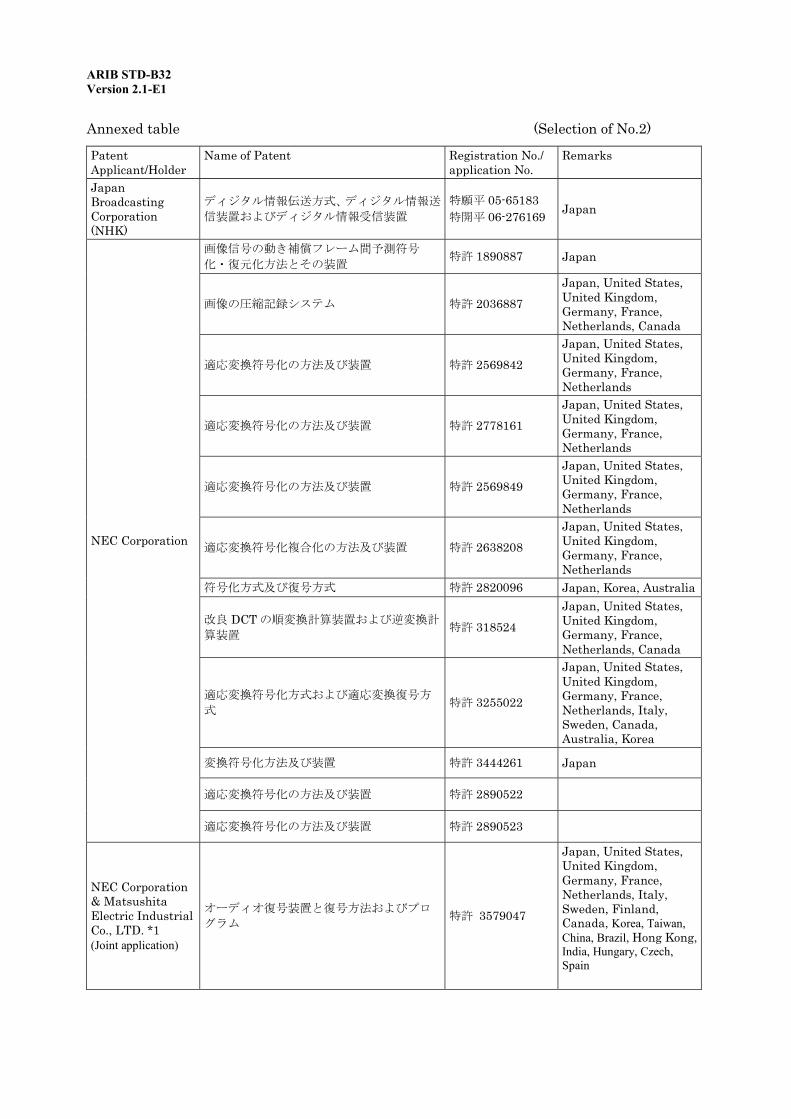
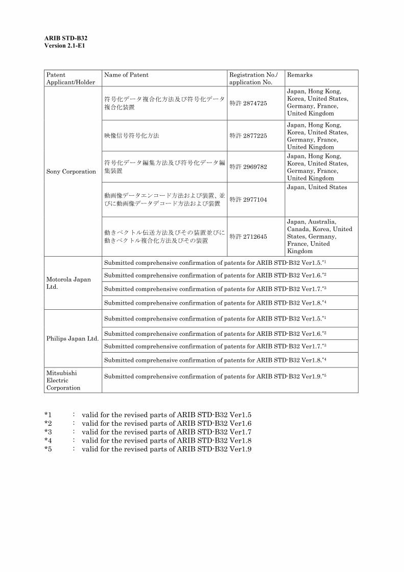
Notice: This standard does not describe industrial proprietary rights mandatory to this standard. However, the owner of industrial proprietary rights is expressed as "Industrial proprietary rights related to this standard, listed in the Annex below, are possessed by the applicant shown in the list. However, execution of the rights listed in the Annex below is permitted indiscriminately, without exclusion, under appropriate conditions, to the user of this standard. If the user of this standard possesses the mandatory industrial proprietary rights for all or part of the contents specified in this standard, and when he asserts those rights, it is not applicable."
ARIB STD-B32 Version 2.1-E1
Annexed table (Selection of No.2)
Patent Applicant/Holder
Name of Patent Registration No./ application No.
Remarks
Japan Broadcasting Corporation (NHK)
ディジタル情報伝送方式、ディジタル情報送
信装置およびディジタル情報受信装置 特願平 05-65183 特開平 06-276169 Japan
画像信号の動き補償フレーム間予測符号
化・復元化方法とその装置 特許 1890887 Japan
画像の圧縮記録システム 特許 2036887 Japan, United States, United Kingdom, Germany, France, Netherlands, Canada
適応変換符号化の方法及び装置 特許 2569842 Japan, United States, United Kingdom, Germany, France, Netherlands
適応変換符号化の方法及び装置 特許 2778161 Japan, United States, United Kingdom, Germany, France, Netherlands
適応変換符号化の方法及び装置 特許 2569849 Japan, United States, United Kingdom, Germany, France, Netherlands
適応変換符号化複合化の方法及び装置 特許 2638208 Japan, United States, United Kingdom, Germany, France, Netherlands
符号化方式及び復号方式 特許 2820096 Japan, Korea, Australia
改良 DCT の順変換計算装置および逆変換計
算装置 特許 318524 Japan, United States, United Kingdom, Germany, France, Netherlands, Canada
適応変換符号化方式および適応変換復号方
式 特許 3255022
Japan, United States, United Kingdom, Germany, France, Netherlands, Italy, Sweden, Canada, Australia, Korea
変換符号化方法及び装置 特許 3444261 Japan
適応変換符号化の方法及び装置 特許 2890522
NEC Corporation
適応変換符号化の方法及び装置 特許 2890523
NEC Corporation & Matsushita Electric Industrial Co., LTD. *1 (Joint application)
オーディオ復号装置と復号方法およびプロ
グラム 特許 3579047
Japan, United States, United Kingdom, Germany, France, Netherlands, Italy, Sweden, Finland, Canada, Korea, Taiwan, China, Brazil, Hong Kong, India, Hungary, Czech, Spain

ARIB STD-B32 Version 2.1-E1
Patent Applicant/Holder
Name of Patent Registration No./ application No.
Remarks
オーディオ復号化装置およびオーディオ復
号化方法 特許 3646938
Japan, United States, United Kingdom, Germany, France, Netherlands, Italy, Sweden, Finland, Canada, Korea, Taiwan, China, Brazil, Hong Kong, India, Hungary, Czech, Spain
NEC Corporation & Matsushita Electric Industrial Co., LTD. *1 (Joint application)
オーディオ復号装置およびオーディオ復号
方法 特許 3646939
Japan, United States, United Kingdom, Germany, France, Netherlands, Italy, Sweden, Finland, Canada, Korea, Taiwan, China, Brazil, Hong Kong, India, Hungary, Czech, Spain
画像信号のフレーム間内挿符号化方法とそ
の装置 特許 1949701 Japan, (MPEG Essential Patent)
動き補償予測方法とそれを用いた画像信号
符号化方法 特許 2699703 Japan, (MPEG Essential Patent)
画像信号符号化装置と画像信号復号化装置
及び画像信号符号化方法と画像信号復号化
方法 特許 2695244 Japan, (MPEG
Essential Patent)
Matsushita Electric Industrial Co., LTD.
画像符号化方法及び画像符号化装置 特許 2684941 Japan, (MPEG Essential Patent)
音声信号圧縮方法及びメモリ書き込み方法 特許 1952835 Japan
オーディオ信号処理方法 特許 3200886
Japan, United States, United Kingdom, Germany, France, Austria, Australia, Korea, Hong Kong
オーディオ信号処理方法 特許 3141853
Japan, United States, United Kingdom, Germany, France, Austria, Australia, Korea, Hong Kong
信号符号化又は複合化装置、及び信号符号化
又は複合化方法、並びに記録媒体 WO94/28633
Japan, United States, United Kingdom, Germany, France, Netherlands, Austria, Italy, Spain, Canada, Australia, Korea, China
Sony Corporation
信号符号化方法及び装置、信号複合化方法及
び装置、並びに信号記録媒体 特開平 7-168593
Japan, United Stares, United Kingdom, Germany, France, Korea, Taiwan, China, Malaysia, Indonesia, India, Thailand, Mexico, Turkey
ARIB STD-B32 Version 2.1-E1
Patent Applicant/Holder
Name of Patent Registration No./ application No.
Remarks
符号化データ複合化方法及び符号化データ
複合化装置 特許 2874725
Japan, Hong Kong, Korea, United States, Germany, France, United Kingdom
映像信号符号化方法 特許 2877225 Japan, Hong Kong, Korea, United States, Germany, France, United Kingdom
符号化データ編集方法及び符号化データ編
集装置 特許 2969782 Japan, Hong Kong, Korea, United States, Germany, France, United Kingdom
動画像データエンコード方法および装置、並
びに動画像データデコード方法および装置 特許 2977104
Japan, United States
Sony Corporation
動きベクトル伝送方法及びその装置並びに
動きベクトル複合化方法及びその装置 特許 2712645
Japan, Australia, Canada, Korea, United States, Germany, France, United Kingdom
Submitted comprehensive confirmation of patents for ARIB STD-B32 Ver1.5.*1
Submitted comprehensive confirmation of patents for ARIB STD-B32 Ver1.6.*2
Submitted comprehensive confirmation of patents for ARIB STD-B32 Ver1.7.*3
Motorola Japan Ltd.
Submitted comprehensive confirmation of patents for ARIB STD-B32 Ver1.8.*4
Submitted comprehensive confirmation of patents for ARIB STD-B32 Ver1.5.*1
Submitted comprehensive confirmation of patents for ARIB STD-B32 Ver1.6.*2
Submitted comprehensive confirmation of patents for ARIB STD-B32 Ver1.7.*3 Philips Japan Ltd.
Submitted comprehensive confirmation of patents for ARIB STD-B32 Ver1.8.*4
Mitsubishi Electric Corporation
Submitted comprehensive confirmation of patents for ARIB STD-B32 Ver1.9.*5
*1 : valid for the revised parts of ARIB STD-B32 Ver1.5 *2 : valid for the revised parts of ARIB STD-B32 Ver1.6 *3 : valid for the revised parts of ARIB STD-B32 Ver1.7 *4 : valid for the revised parts of ARIB STD-B32 Ver1.8 *5 : valid for the revised parts of ARIB STD-B32 Ver1.9
ARIB STD-B32 Version 2.1-E1
Part 1: Video Signal and Coding System

ARIB STD-B32 Version 2.1-E1
<Blank Page>
ARIB STD-B32 Part 1 Version 2.1-E1
-1-
Part 1: Video Signal and Coding System
Contents
Chapter 1: General Terms..........................................................................................................................3
1.1 Objective..........................................................................................................................................3
1.2 Scope................................................................................................................................................3
1.3 References .......................................................................................................................................3
1.3.1 Normative documents...............................................................................................................3
1.4 Terminology ....................................................................................................................................4
1.4.1 Abbreviations ............................................................................................................................4
Chapter 2: Video Input Format..................................................................................................................5
2.1 Video signal.....................................................................................................................................5
2.2 Sampled values of signals ..............................................................................................................6
2.3 Scanning direction ..........................................................................................................................6
2.4 Video signal parameters.................................................................................................................6
Chapter 3: Video Coding System .............................................................................................................19
Chapter 4: Video Compression Procedure, Transmission Procedure, and Signal Configuration after Coding .....................................................................................................................................21
4.1 Compression and transmission procedures ................................................................................21
4.2 Signal configuration .....................................................................................................................23
Chapter 5: Restrictions on Coding Parameters.......................................................................................25
5.1 Restrictions on video coding parameters for television services ...............................................25
5.2 Desirable encoding areas .............................................................................................................30
Appendix: Operating Guidelines..............................................................................................................31
Chapter 1: General Terms........................................................................................................................31
1.1 Objective........................................................................................................................................31
1.2 Scope..............................................................................................................................................31
ARIB STD-B32 Part 1 Version 2.1-E1
-2-
1.3 References .....................................................................................................................................31
1.3.1 Normative documents.............................................................................................................31
1.4 Terminology ..................................................................................................................................31
1.4.1 Abbreviations ..........................................................................................................................31
Chapter 2: Transmitting Sequence Header and Sequence End Code ...................................................33
2.1 Transmitting sequence header (sequence_header) ....................................................................33
2.2 Transmitting sequence end code (sequence_end_code)..............................................................33
Chapter 3: Channel-hopping time............................................................................................................35
Chapter 4: Seamless Switching................................................................................................................39
4.1 Changing the number of active samples .....................................................................................39
4.2 Changing picture aspect ratio with the 525i television system.................................................39
4.3 Changing bitrate...........................................................................................................................39
4.4 Video format switching method...................................................................................................40
4.4.1 Procedure for perfect seamless switching (method with which sequence_end_code is transmitted) .............................................................................................................................41
4.4.2 Simple procedure for switching between SDTV and HDTV (method by which sequence_end_code is not transmitted)..................................................................................44
Chapter 5: Example of Encoding Film Materials ...................................................................................47
ARIB STD-B32 Part 1 Version 2.1-E1
-3-
Chapter 1: General Terms
1.1 Objective The purpose of this standard is to define a video signal and video coding system for digital terrestrial broadcasting among the various types of standard television broadcasting and high-definition television broadcasting handled by broadcasting stations (hereinafter referred to as digital terrestrial television broadcasting), digital broadcasting among standard television broadcasting, high-definition television broadcasting, ultrashort-wave broadcasting, and data broadcasting handled by broadcast satellite stations using frequency ranges greater than 11.7 GHz and less than or equal to 12.2 GHz (hereinafter referred to as BS digital broadcasting), standard television broadcasting, high-definition television broadcasting, ultrashort-wave broadcasting, and data broadcasting through broadband transmission systems using frequency ranges greater than 12.2 GHz and less than or equal to 12.75 GHz handled by broadcast satellite stations (hereinafter referred to as broadband CS digital broadcasting), that comply with the “Standard transmission system for digital broadcasting among standard television broadcasting and the like” (Ordinance No. 26 of the Ministry of Public Management, Home Affairs, Posts and Telecommunications, 2003).
1.2 Scope This standard applies to video signals using PES packets among the various types of video signals that comply with the “Standard transmission system for digital broadcasting among standard television broadcasting and the like” (Ordinance No. 26 of the Ministry of Public Management, Home Affairs, Posts and Telecommunications, 2003). This standard also applies to all digital terrestrial television, BS digital, and broadband CS digital broadcasting, unless otherwise specified.
1.3 References 1.3.1 Normative documents
This standard incorporates excerpts from the following documents:
(1) “Standard transmission system for digital broadcasting among standard television broadcasting and the like (Ordinance No. 26 of the Ministry of Public Management, Home Affairs, Posts and Telecommunications, 2003)” (hereinafter referred to as “ordinance”)
(2) “Defining compression and transmission procedures for a video signal using PES packets among the various types of video signals, and compression and transmission procedures for an audio signal using PES packets among the various types of audio signals (Notification No. 38 of the Ministry of Public Management, Home Affairs, Posts and Telecommunications, 2003)” (hereinafter referred to as “notification”)
(3) ISO/IEC 13818-2:2000 | ITU-T Rec. H.262: Information technology – Generic coding of moving pictures and associated audio information: Video (hereinafter referred to as “MPEG-2 Video Standard”)
ARIB STD-B32 Part 1 Version 2.1-E1
-4-
1.4 Terminology 1.4.1 Abbreviations
DCT Discrete Cosine Transform DTS Decoding Time-Stamp GOP Group of Pictures HL High Level H14L High-1440 Level ML Main Level MP Main Profile MPEG Moving Picture Experts Group PES Packetized Elementary Stream PTS Presentation Time-Stamp
ARIB STD-B32 Part 1 Version 2.1-E1
-5-
Chapter 2: Video Input Format
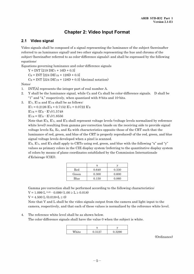
2.1 Video signal Video signals shall be composed of a signal representing the luminance of the subject (hereinafter referred to as luminance signal) and two other signals representing the hue and chroma of the subject (hereinafter referred to as color-difference signals); and shall be expressed by the following equations: Equations governing luminance and color-difference signals
Y = INT [219 DE’Y + 16D + 0.5] CR = INT [224 DE’CR + 128D + 0.5] CB = INT [224 DE’CB + 128D + 0.5] (decimal notation)
Notes: 1. INT[A] represents the integer part of real number A. 2. Y shall be the luminance signal, while CR and CB shall be color-difference signals. D shall be
“1” and “4,” respectively, when quantized with 8-bits and 10-bits. 3. E’Y, E’CR and E’CB shall be as follows: E’Y = 0.2126 E’R + 0.7152 E’G + 0.0722 E’B E’CR = (E’R - E’Y)/1.5748 E’CB = (E’B - E’Y)/1.8556 Note that E’R, E’G, and E’B shall represent voltage levels (voltage levels normalized by reference
white level) resulting from gamma pre-correction (made on the receiving side to provide signal voltage levels ER, EG, and EB with characteristics opposite those of the CRT such that the luminance of red, green, and blue of the CRT is properly reproduced) of the red, green, and blue signal voltage levels developed when a pixel is scanned.
E’R, E’G, and E’B shall apply to CRTs using red, green, and blue with the following “x” and “y” values as primary colors in the CIE display system (referring to the quantitative display system of colors by means of plane coordinates established by the Commission Internationale d’Eclairage (CIE)).
x y Red 0.640 0.330
Green 0.300 0.600 Blue 0.150 0.060
Gamma pre-correction shall be performed according to the following characteristics: V = 1.099 L 0.45 - 0.099 (1.00 ≥ L ≥ 0.018) V = 4.500 L (0.018>L ≥ 0) Note that V and L shall be the video signals output from the camera and light input to the
camera, respectively, and that each of these values is normalized by the reference white level.
4. The reference white level shall be as shown below. The color-difference signals shall have the value 0 when the subject is white.
x y White 0.3127 0.3290
(Ordinance)
ARIB STD-B32 Part 1 Version 2.1-E1
-6-
2.2 Sampled values of signals The sampled values for luminance and color-difference signals shall be quantized by 8- or 10-bit.
(Ordinance) 2.3 Scanning direction Pictures are to be scanned at a constant rate from left to right and from top to bottom.
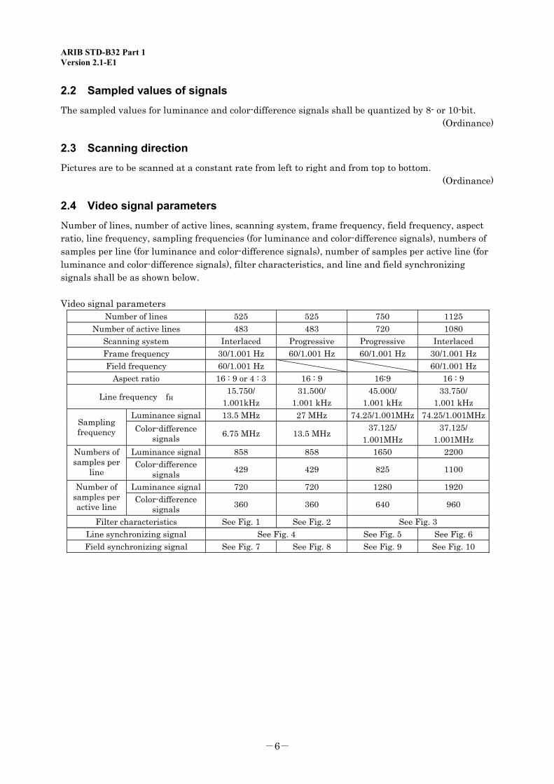
(Ordinance) 2.4 Video signal parameters Number of lines, number of active lines, scanning system, frame frequency, field frequency, aspect ratio, line frequency, sampling frequencies (for luminance and color-difference signals), numbers of samples per line (for luminance and color-difference signals), number of samples per active line (for luminance and color-difference signals), filter characteristics, and line and field synchronizing signals shall be as shown below. Video signal parameters
Number of lines 525 525 750 1125 Number of active lines 483 483 720 1080
Scanning system Interlaced Progressive Progressive Interlaced Frame frequency 30/1.001 Hz 60/1.001 Hz 60/1.001 Hz 30/1.001 Hz Field frequency 60/1.001 Hz 60/1.001 Hz
Aspect ratio 16 : 9 or 4 : 3 16 : 9 16:9 16 : 9
Line frequency fH 15.750/ 1.001kHz
31.500/ 1.001 kHz
45.000/ 1.001 kHz
33.750/ 1.001 kHz
Luminance signal 13.5 MHz 27 MHz 74.25/1.001MHz 74.25/1.001MHzSampling frequency Color-difference
signals 6.75 MHz 13.5 MHz 37.125/ 1.001MHz
37.125/ 1.001MHz
Luminance signal 858 858 1650 2200 Numbers of samples per
line Color-difference
signals 429 429 825 1100
Luminance signal 720 720 1280 1920 Number of samples per active line
Color-difference signals 360 360 640 960
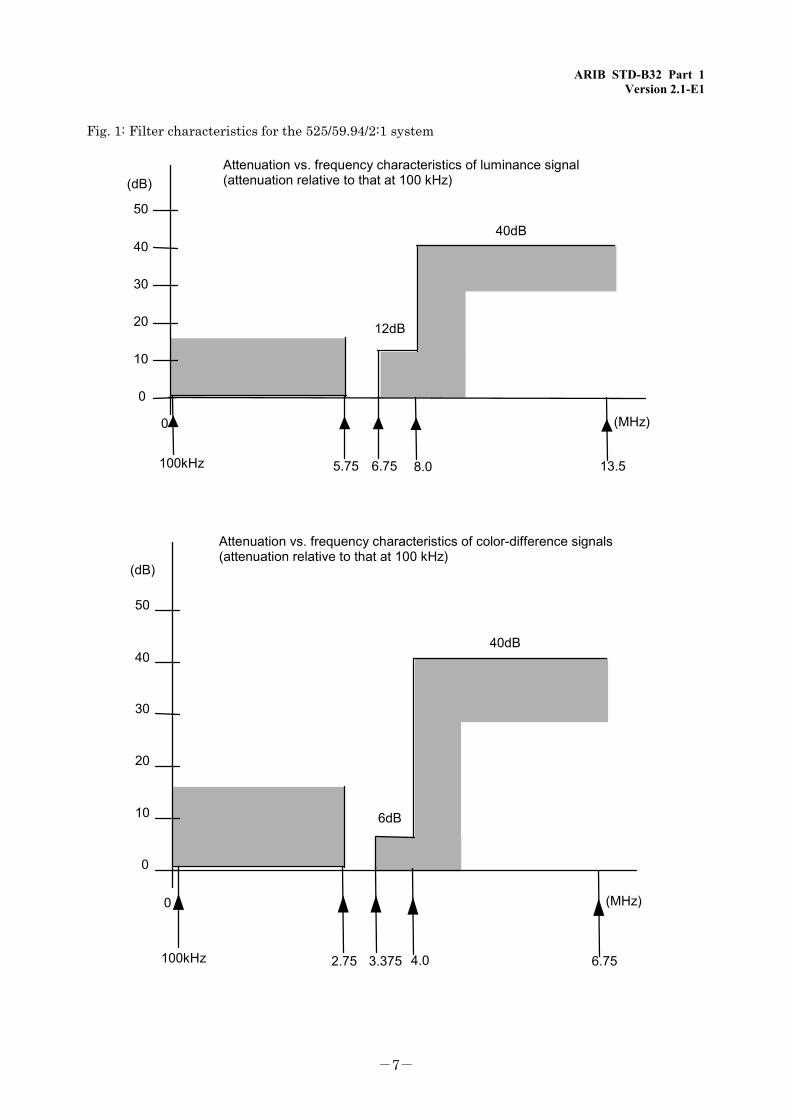
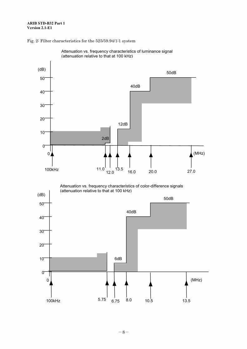
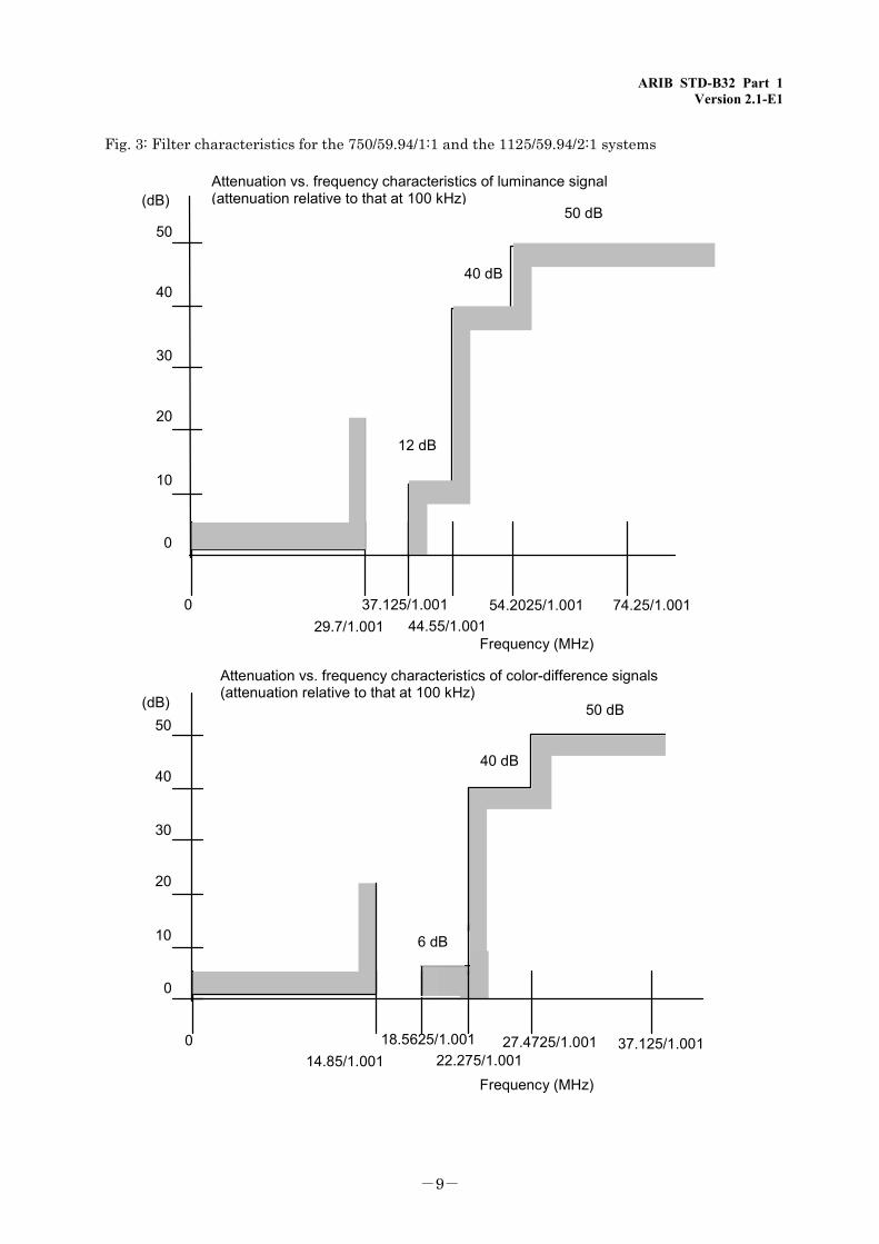
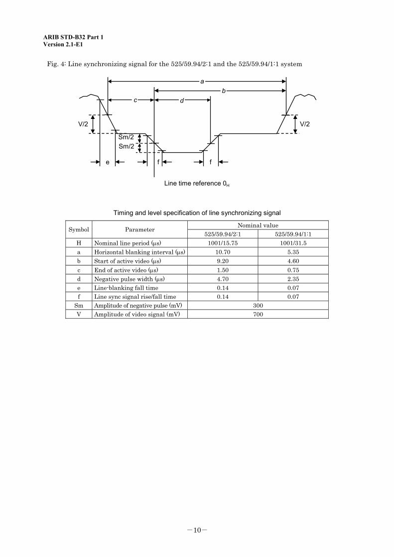
Filter characteristics See Fig. 1 See Fig. 2 See Fig. 3 Line synchronizing signal See Fig. 4 See Fig. 5 See Fig. 6 Field synchronizing signal See Fig. 7 See Fig. 8 See Fig. 9 See Fig. 10
ARIB STD-B32 Part 1 Version 2.1-E1
-7-
Fig. 1: Filter characteristics for the 525/59.94/2:1 system
0
10
20
30
40
50
0
12dB
40dB
(dB)
(MHz)
100kHz 5.75 6.75 8.0 13.5
Attenuation vs. frequency characteristics of luminance signal(attenuation relative to that at 100 kHz)
Attenuation vs. frequency characteristics of color-difference signals(attenuation relative to that at 100 kHz)
4.0
0
10
20
30
40
50
0
6dB
40dB
(dB)
(MHz)
100kHz 2.75 3.375 6.75
ARIB STD-B32 Part 1 Version 2.1-E1
-8-
Fig. 2: Filter characteristics for the 525/59.94/1:1 system
0
10
20
30
40
50
0
6dB
40dB
50dB(dB)
(MHz)
100kHz 5.75 6.75 8.0 13.510.5
0
10
20
30
40
50
0
2dB
12dB
40dB
50dB(dB)
(MHz)
100kHz12.0
11.0 13.516.0 27.020.0
Attenuation vs. frequency characteristics of luminance signal(attenuation relative to that at 100 kHz)
Attenuation vs. frequency characteristics of color-difference signals(attenuation relative to that at 100 kHz)
ARIB STD-B32 Part 1 Version 2.1-E1
-9-
Fig. 3: Filter characteristics for the 750/59.94/1:1 and the 1125/59.94/2:1 systems
29.7/1.00137.125/1.001
44.55/1.00154.2025/1.001 74.25/1.0010
40
30
20
10
0
(dB)
12 dB
40 dB
50 dB50
Frequency (MHz)
Attenuation vs. frequency characteristics of color-difference signals(attenuation relative to that at 100 kHz)
14.85/1.00118.5625/1.001
22.275/1.00127.4725/1.001 37.125/1.0010
50
40
30
20
10
0
(dB)
40 dB
50 dB
6 dB
Attenuation vs. frequency characteristics of luminance signal(attenuation relative to that at 100 kHz)
Frequency (MHz)
ARIB STD-B32 Part 1 Version 2.1-E1
-10-
Fig. 4: Line synchronizing signal for the 525/59.94/2:1 and the 525/59.94/1:1 system
ab
c d
f
V/2 V/2
Sm/2Sm/2
fe
Line time reference 0H
Timing and level specification of line synchronizing signal
Nominal value Symbol Parameter 525/59.94/2:1 525/59.94/1:1
H Nominal line period (μs) 1001/15.75 1001/31.5 a Horizontal blanking interval (μs) 10.70 5.35 b Start of active video (μs) 9.20 4.60 c End of active video (μs) 1.50 0.75 d Negative pulse width (μs) 4.70 2.35 e Line-blanking fall time 0.14 0.07 f Line sync signal rise/fall time 0.14 0.07
Sm Amplitude of negative pulse (mV) 300 V Amplitude of video signal (mV) 700
ARIB STD-B32 Part 1 Version 2.1-E1
-11-
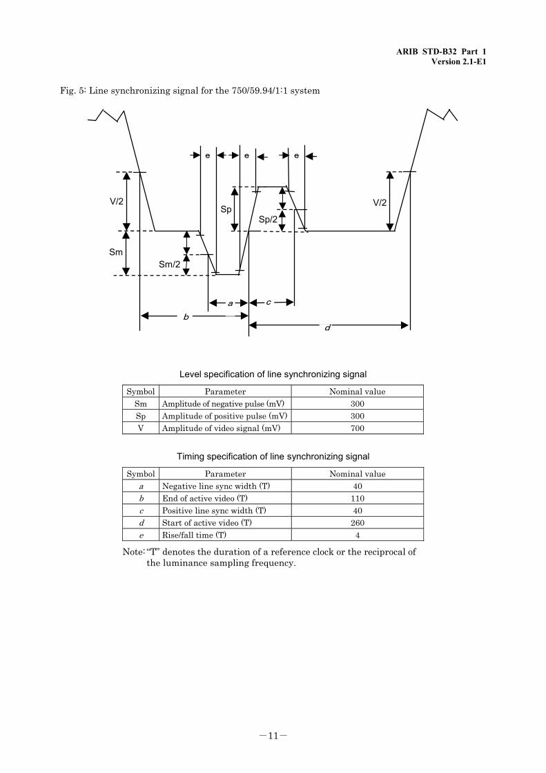
Fig. 5: Line synchronizing signal for the 750/59.94/1:1 system
db
a c
e e
V/2Sp
V/2
Sm/2Sm
Sp/2
e
Level specification of line synchronizing signal
Symbol Parameter Nominal valueSm Amplitude of negative pulse (mV) 300Sp Amplitude of positive pulse (mV) 300V Amplitude of video signal (mV) 700
Timing specification of line synchronizing signal
Symbol Parameter Nominal valuea Negative line sync width (T) 40b End of active video (T) 110c Positive line sync width (T) 40d Start of active video (T) 260e Rise/fall time (T) 4
Note: “T” denotes the duration of a reference clock or the reciprocal of
the luminance sampling frequency.
ARIB STD-B32 Part 1 Version 2.1-E1
-12-
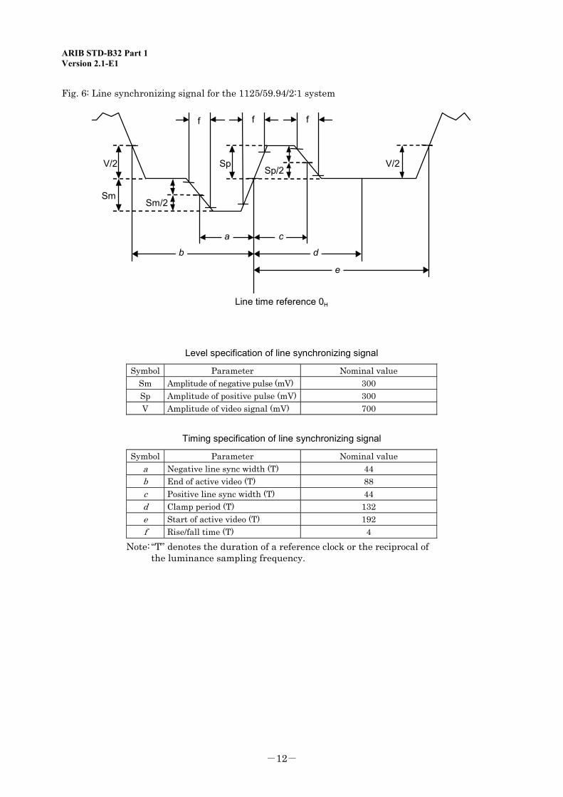
Fig. 6: Line synchronizing signal for the 1125/59.94/2:1 system
f f
V/2 V/2Sp/2
Sm/2
f
Sm
Sp
e
a c
b d
Line time reference 0H
Level specification of line synchronizing signal
Symbol Parameter Nominal valueSm Amplitude of negative pulse (mV) 300Sp Amplitude of positive pulse (mV) 300V Amplitude of video signal (mV) 700
Timing specification of line synchronizing signal
Symbol Parameter Nominal value a Negative line sync width (T) 44 b End of active video (T) 88 c Positive line sync width (T) 44 d Clamp period (T) 132 e Start of active video (T) 192 f Rise/fall time (T) 4
Note: “T” denotes the duration of a reference clock or the reciprocal of the luminance sampling frequency.
ARIB STD-B32 Part 1 Version 2.1-E1
-13-
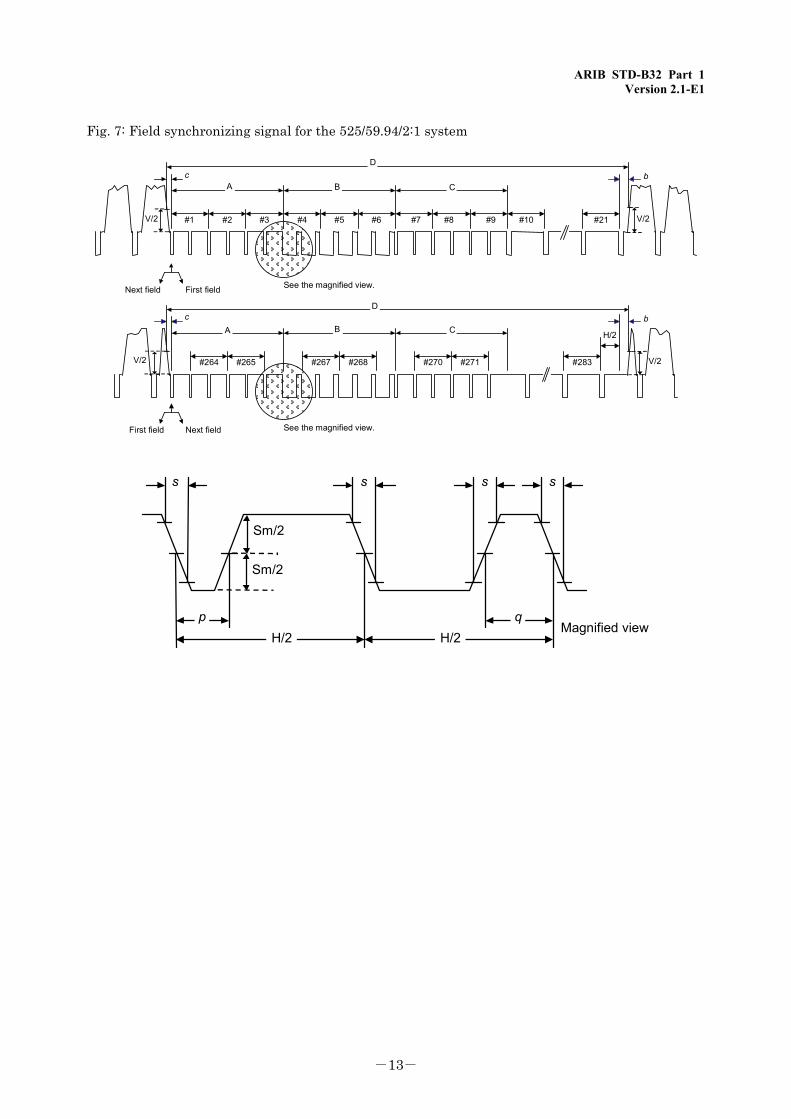
Fig. 7: Field synchronizing signal for the 525/59.94/2:1 system
#1 #2 #3 #4 #5 #6 #7 #8 #9 #10 #21
A B C
D
First fieldNext field See the magnified view.
c
D
A B C
#264 #265 #267 #268 #270 #271 #283
First field Next field See the magnified view.
c
b
b
H/2
V/2
V/2
V/2
V/2
H/2 H/2p q
ssss
Magnified view
Sm/2
Sm/2
ARIB STD-B32 Part 1 Version 2.1-E1
-14-
Timing specification of field synchronizing signal
Symbol Parameter Nominal valueF Field-scanning interval (ms) 1001/30D Field-blanking interval 21H + aA Equivalent pulse interval 3HB Field sync pulse interval 3HC Equivalent pulse interval 3Hs Line sync pulse rise/fall time 0.14p Equivalent pulse width (μs) 2.30q Field serration pulse width (μs) 4.70
Note: Note that “H”, “a”, “b”, “c”, “Sm”, and “V” shall have the values shown in the table under Fig. 4.
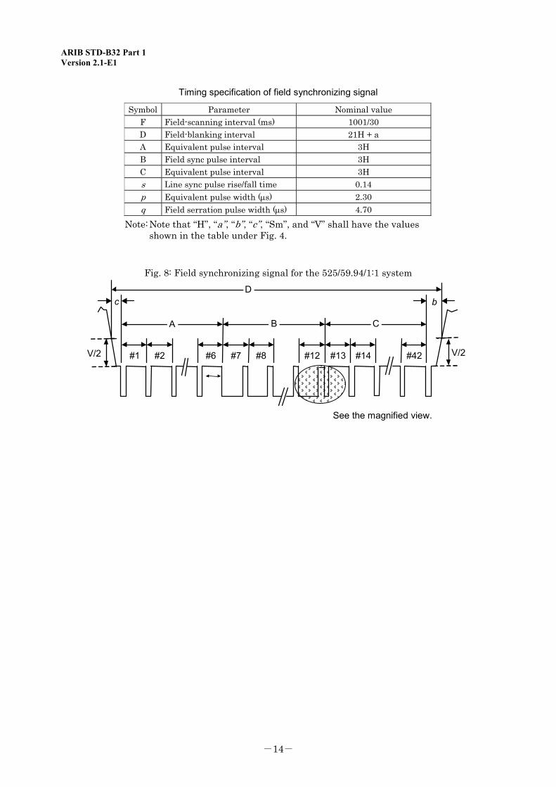
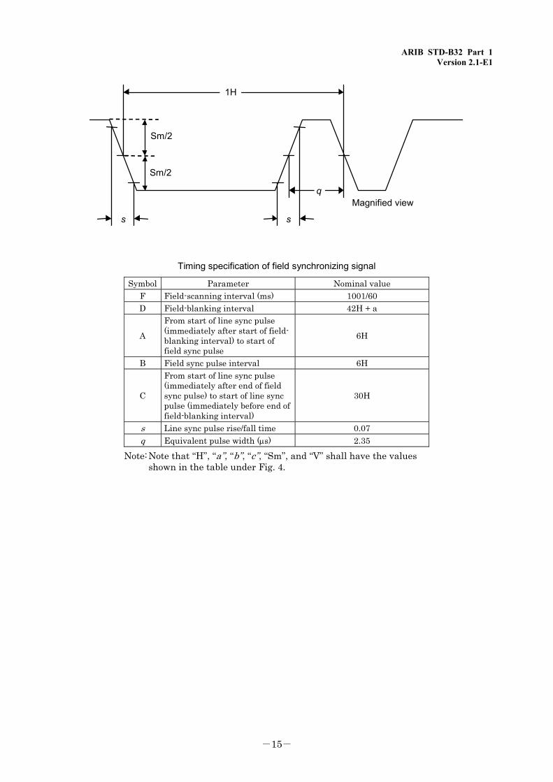
Fig. 8: Field synchronizing signal for the 525/59.94/1:1 system
A B C
D
#1 #2 #6 #7 #8 #13#12 #14 #42
c
See the magnified view.
b
V/2 V/2
ARIB STD-B32 Part 1 Version 2.1-E1
-15-
1H
q
Sm/2
Sm/2
s
Magnified view
s
Timing specification of field synchronizing signal
Symbol Parameter Nominal valueF Field-scanning interval (ms) 1001/60D Field-blanking interval 42H + a
A
From start of line sync pulse(immediately after start of field-blanking interval) to start offield sync pulse
6H
B Field sync pulse interval 6H
C
From start of line sync pulse(immediately after end of fieldsync pulse) to start of line syncpulse (immediately before end offield-blanking interval)
30H
s Line sync pulse rise/fall time 0.07q Equivalent pulse width (μs) 2.35
Note: Note that “H”, “a”, “b”, “c”, “Sm”, and “V” shall have the values shown in the table under Fig. 4.
ARIB STD-B32 Part 1 Version 2.1-E1
-16-
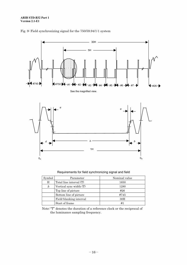
Fig. 9: Field synchronizing signal for the 750/59.94/1:1 system
30H
5H
#745 #750 #1 #26
e e
d h b
1H
0H 0H
See the magnified view.
#2 #3 #4 #5 #6 #7
Requirements for field synchronizing signal and field
Symbol Parameter Nominal value H Total line interval (T) 1650 h Vertical sync width (T) 1280 Top line of picture #26 Bottom line of picture #745 Field-blanking interval 30H Start of frame #1
Note: “T” denotes the duration of a reference clock or the reciprocal of the luminance sampling frequency.
ARIB STD-B32 Part 1 Version 2.1-E1
-17-
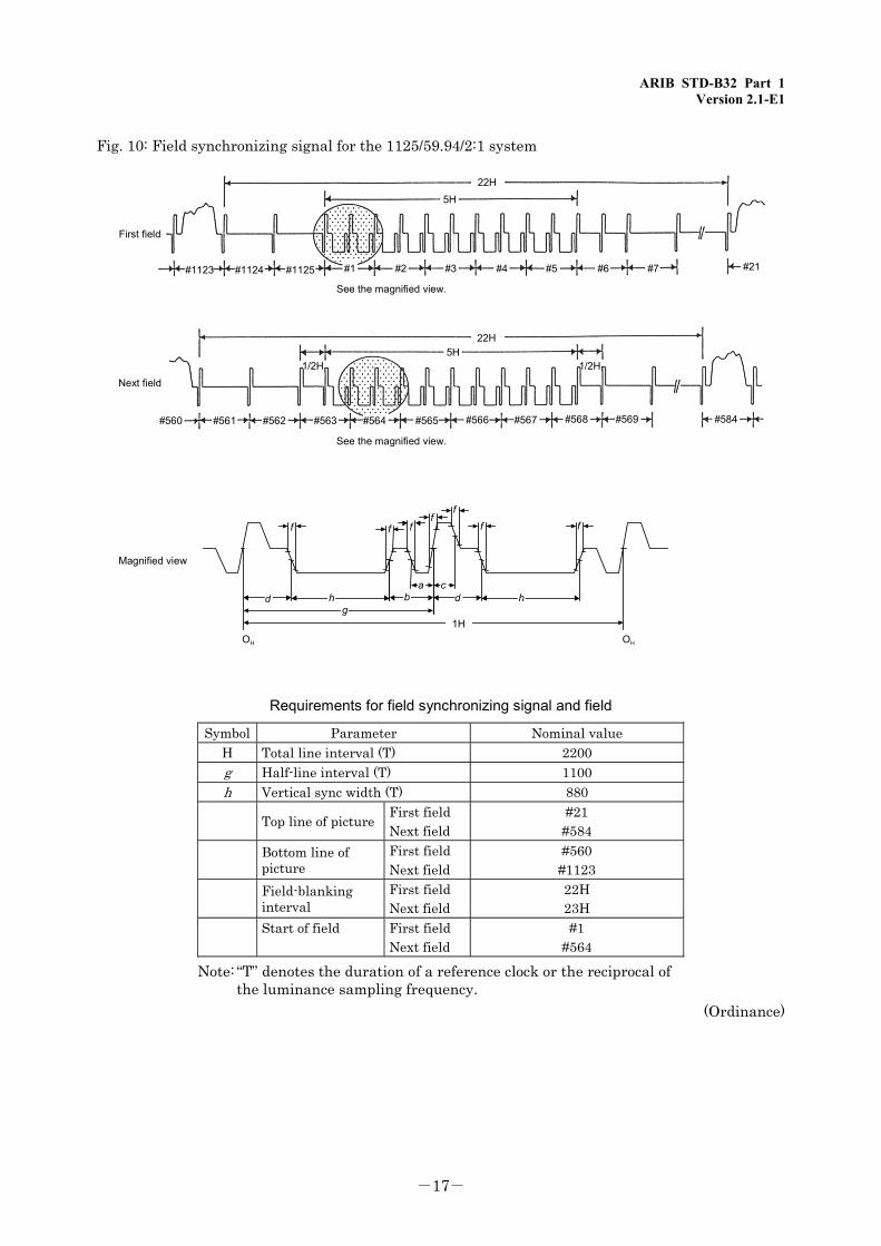
Fig. 10: Field synchronizing signal for the 1125/59.94/2:1 system
22H5H
#21#7#6#5#4#3#2#1#1125#1124#1123
First field
Next field
#560 #563#562#561 #566#565#564 #569#568#567 #584
See the magnified view.
See the magnified view.
22H5H
1/2H 1/2H
Magnified view
OH
f f
dg
h
f
f f f
ab
cd h
f
OH
1H
Requirements for field synchronizing signal and field
Symbol Parameter Nominal value H Total line interval (T) 2200 g Half-line interval (T) 1100 h Vertical sync width (T) 880
Top line of picture First field Next field
#21 #584
Bottom line of picture
First field Next field
#560 #1123
Field-blanking interval
First field Next field
22H 23H
Start of field
First field Next field
#1 #564
Note: “T” denotes the duration of a reference clock or the reciprocal of the luminance sampling frequency.
(Ordinance)

ARIB STD-B32 Part 1 Version 2.1-E1
-18-
<Blank Page>
ARIB STD-B32 Part 1 Version 2.1-E1
-19-
Chapter 3: Video Coding System
Video coding shall be achieved by a combination of the systems defined below. Video compression and transmission procedures shall comply with the notification separately issued by the Minister of Public Management, Home Affairs, Posts and Telecommunications. (See Chapter 4.) (1) Motion compensated prediction coding (system in which the amount of information to be
transmitted is reduced by detecting the motion vectors for previous and future frames (or fields) and sending two signals: (a) signal representing the difference between the original signal and motion compensated frame (or field) signal , and (b) motion vector information)
(2) Discrete cosine transform (system in which the amount of information to be transmitted is reduced by transforming the original picture from 8 × 8 pixels to spatial frequency components, and quantizing these frequency components in consideration of their visual characteristics.
(3) Variable length coding (system in which the number of bits to be transmitted is reduced by representing codes that are statistically high and low in frequency of occurrence, respectively, using short and long bit strings)
(Ordinance)

ARIB STD-B32 Part 1 Version 2.1-E1
-20-
<Blank Page>
ARIB STD-B32 Part 1 Version 2.1-E1
-21-
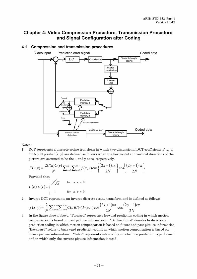
Chapter 4: Video Compression Procedure, Transmission Procedure, and Signal Configuration after Coding
4.1 Compression and transmission procedures
DCT Quantization
Video inputVariable length
coding
Inversequantization
InverseDCT
Predictionmemory 1
Predictionmemory 2
Motion vectordetection
Variable lengthcoding
Motion compensation
Motion vector
Forward
Bi-directional
Backward
Intra
Prediction error signal Coded data
Coded data
Notes: 1. DCT represents a discrete cosine transform in which two-dimensional DCT coefficients F (u, v)
for N × N pixels f (x, y) are defined as follows when the horizontal and vertical directions of the picture are assumed to be the × and y axes, respectively:
( ) ( )⎭⎬⎫
⎩⎨⎧ +
⎭⎬⎫
⎩⎨⎧ +
= ∑ ∑−=−
= Nvy
Nuxyxf
NvCuCvuF N
x
N
y 212cos
212cos),()()(2),( 1
0
1
0
ππ
Provided that
( ) ( )0,for
0,for
1
21
,≠
=
⎪⎪⎩
⎪⎪⎨
⎧
=vu
vuvCuC
2. Inverse DCT represents an inverse discrete cosine transform and is defined as follows:
( ) ( )
Nvy
NuxvuFvCuC
Nyxf N
u
N
v 212cos
212cos),()()(2),( 1
0
1
0
ππ ++= ∑ ∑−
=
−
=
3. In the figure shown above, “Forward” represents forward prediction coding in which motion compensation is based on past picture information. “Bi-directional” denotes bi-directional prediction coding in which motion compensation is based on future and past picture information. “Backward” refers to backward prediction coding in which motion compensation is based on future picture information. “Intra” represents intracoding in which no prediction is performed and in which only the current picture information is used
ARIB STD-B32 Part 1 Version 2.1-E1
-22-
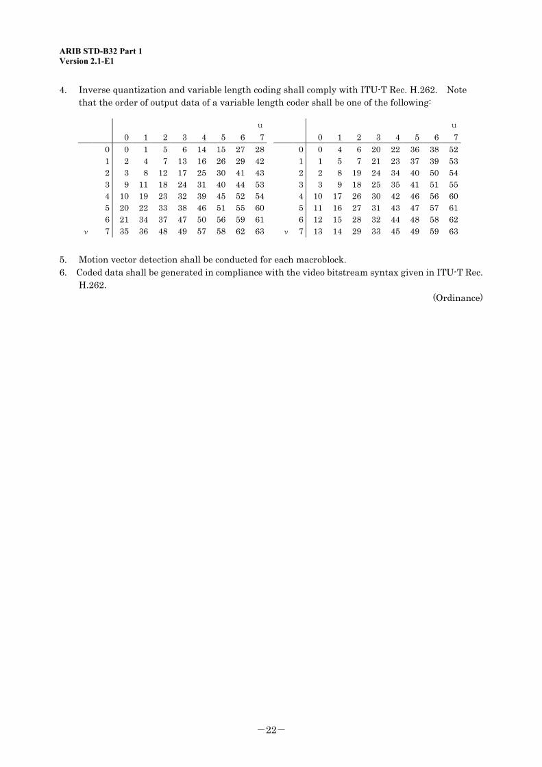
4. Inverse quantization and variable length coding shall comply with ITU-T Rec. H.262. Note that the order of output data of a variable length coder shall be one of the following:
u u
0 1 2 3 4 5 6 7 0 1 2 3 4 5 6 70 0 1 5 6 14 15 27 28 0 0 4 6 20 22 36 38 521 2 4 7 13 16 26 29 42 1 1 5 7 21 23 37 39 532 3 8 12 17 25 30 41 43 2 2 8 19 24 34 40 50 543 9 11 18 24 31 40 44 53 3 3 9 18 25 35 41 51 554 10 19 23 32 39 45 52 54 4 10 17 26 30 42 46 56 605 20 22 33 38 46 51 55 60 5 11 16 27 31 43 47 57 616 21 34 37 47 50 56 59 61 6 12 15 28 32 44 48 58 62
ν 7 35 36 48 49 57 58 62 63 ν 7 13 14 29 33 45 49 59 63
5. Motion vector detection shall be conducted for each macroblock. 6. Coded data shall be generated in compliance with the video bitstream syntax given in ITU-T Rec.
H.262. (Ordinance)
ARIB STD-B32 Part 1 Version 2.1-E1
-23-
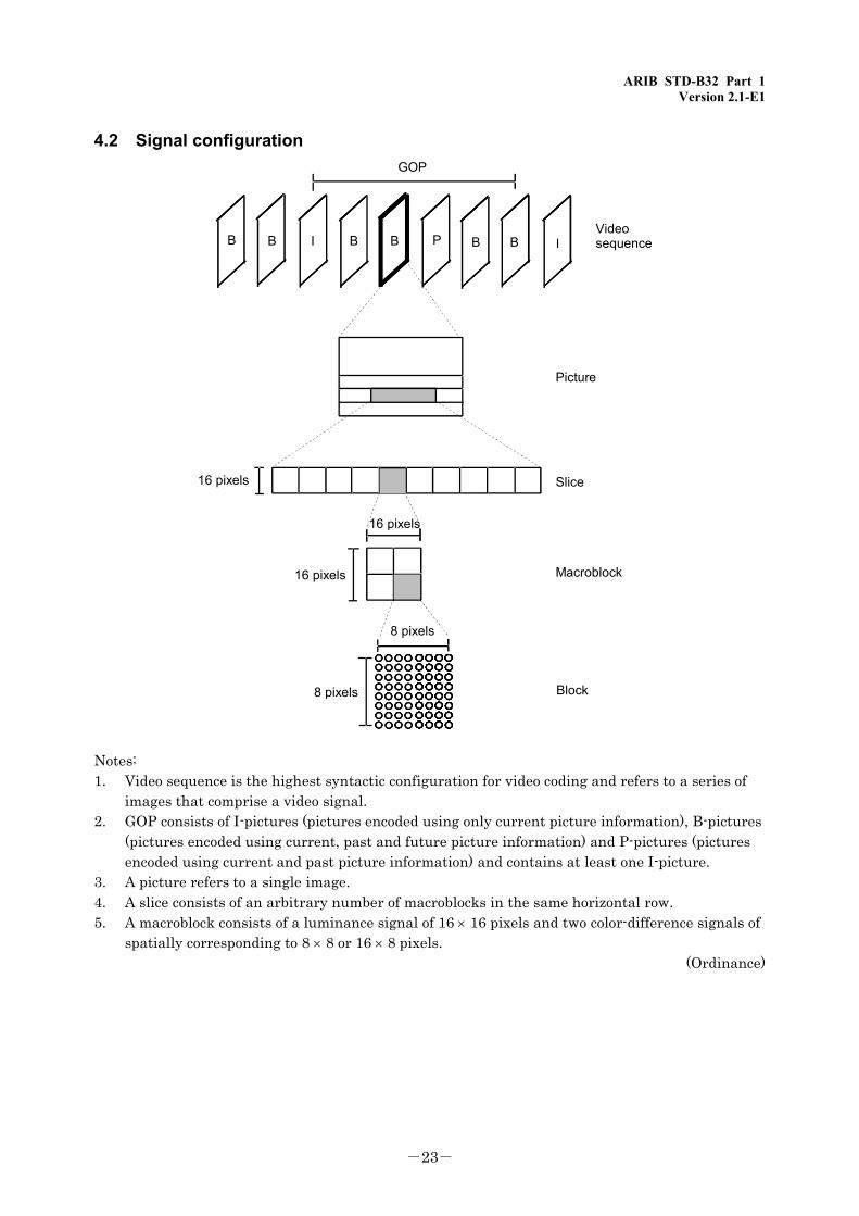
4.2 Signal configuration
16 pixels
16 pixels
16 pixels
8 pixels
8 pixels
I B B PB B B B I
GOP
Picture
Slice
Macroblock
Block
Videosequence
Notes: 1. Video sequence is the highest syntactic configuration for video coding and refers to a series of
images that comprise a video signal. 2. GOP consists of I-pictures (pictures encoded using only current picture information), B-pictures
(pictures encoded using current, past and future picture information) and P-pictures (pictures encoded using current and past picture information) and contains at least one I-picture.
3. A picture refers to a single image. 4. A slice consists of an arbitrary number of macroblocks in the same horizontal row. 5. A macroblock consists of a luminance signal of 16 × 16 pixels and two color-difference signals of
spatially corresponding to 8 × 8 or 16 × 8 pixels. (Ordinance)

ARIB STD-B32 Part 1 Version 2.1-E1
-24-
<Blank Page>
ARIB STD-B32 Part 1 Version 2.1-E1
-25-
Chapter 5: Restrictions on Coding Parameters
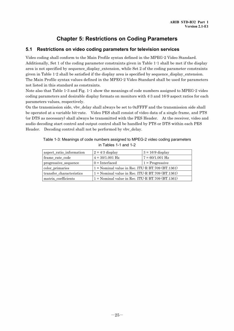
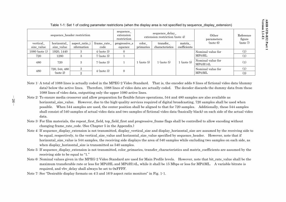
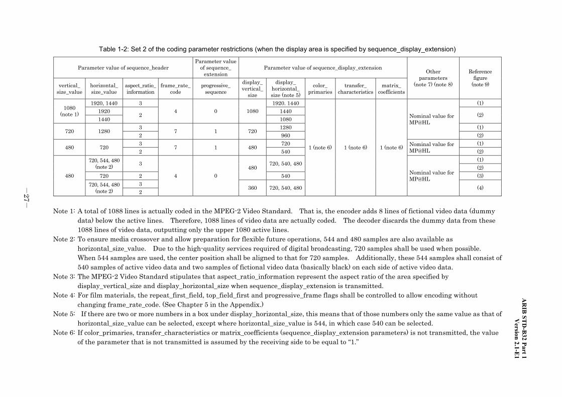
5.1 Restrictions on video coding parameters for television services Video coding shall conform to the Main Profile syntax defined in the MPEG-2 Video Standard. Additionally, Set 1 of the coding parameter constraints given in Table 1-1 shall be met if the display area is not specified by sequence_display_extension, while Set 2 of the coding parameter constraints given in Table 1-2 shall be satisfied if the display area is specified by sequence_display_extension. The Main Profile syntax values defined in the MPEG-2 Video Standard shall be used for parameters not listed in this standard as constraints. Note also that Table 1-3 and Fig. 1-1 show the meanings of code numbers assigned to MPEG-2 video coding parameters and desirable display formats on monitors with 4:3 and 16:9 aspect ratios for each parameters values, respectively. On the transmission side, vbv_delay shall always be set to 0xFFFF and the transmission side shall be operated at a variable bit-rate. Video PES shall consist of video data of a single frame, and PTS (or DTS as necessary) shall always be transmitted with the PES Header. At the receiver, video and audio decoding start control and output control shall be handled by PTS or DTS within each PES Header. Decoding control shall not be performed by vbv_delay.
Table 1-3: Meanings of code numbers assigned to MPEG-2 video coding parameters in Tables 1-1 and 1-2
aspect_ratio_information 2 = 4:3 display 3 = 16:9 display
frame_rate_code 4 = 30/1.001 Hz 7 = 60/1.001 Hz progressive_sequence 0 = Interlaced 1 = Progressive color_primaries 1 = Nominal value in Rec. ITU-R BT.709 (BT.1361) transfer_characteristics 1 = Nominal value in Rec. ITU-R BT.709 (BT.1361) matrix_coefficients 1 = Nominal value in Rec. ITU-R BT.709 (BT.1361)
AR
IB ST
D-B
32 Part 1 V
ersion 2.1-E1
-26
-
Table 1-1: Set 1 of coding parameter restrictions (when the display area is not specified by sequence_display_extension)
sequence_header restriction sequence_ extension restriction
sequence_delay_ extension restriction (note 4)
vertical_ size_value
horizontal_ size_value
aspect_ratio_information
frame_rate_code
progressive_sequence
color_ primaries
transfer_ characteristics
matrix_ coefficients
Other parameters
(note 6)
Reference figure
(note 7)
1080 (note 1) 1920, 1440 3 4 (note 3) 0 (1) 720 1280 3 7 (note 3) 1
Nominal value for MP@HL (1)
480 720 3 7 (note 3) 1 Nominal value for MP@H14L (1)
3 (1) 480 720, 544, 480 (note 2) 2
4 (note 3) 0
1 (note 5) 1 (note 5) 1 (note 5)
Nominal value for MP@ML (3)
Note 1: A total of 1088 lines is actually coded in the MPEG-2 Video Standard. That is, the encoder adds 8 lines of fictional video data (dummy
data) below the active lines. Therefore, 1088 lines of video data are actually coded. The decoder discards the dummy data from these 1088 lines of video data, outputting only the upper 1080 active lines.
Note 2: To ensure media crossover and allow preparation for flexible future operations, 544 and 480 samples are also available as horizontal_size_value. However, due to the high-quality services required of digital broadcasting, 720 samples shall be used when possible. When 544 samples are used, the center position shall be aligned to that for 720 samples. Additionally, these 544 samples shall consist of 540 samples of actual video data and two samples of fictional video data (basically black) on each side of the actual video data.
Note 3: For film materials, the repeat_first_field, top_field_first and progressive_frame flags shall be controlled to allow encoding without changing frame_rate_code. (See Chapter 5 in the Appendix.)
Note 4: If sequence_display_extension is not transmitted, display_vertical_size and display_horizontal_size are assumed by the receiving side to be equal, respectively, to the vertical_size_value and horizontal_size_value specified by sequence_header. However, note that if horizontal_size_value is 544 samples, the receiving side displays the area of 540 samples while excluding two samples on each side, as when display_horizontal_size is transmitted as 540 samples.
Note 5: If sequence_display_extension is not transmitted, color_primaries, transfer_characteristics and matrix_coefficients are assumed by the receiving side to be equal to “1.”
Note 6: Nominal values given in the MPEG-2 Video Standard are used for Main Profile levels. However, note that bit_rate_value shall be the maximum transferable rate or less for MP@HL and MP@H14L, while it shall be 15 Mbps or less for MP@ML. A variable bitrate is required, and vbv_delay shall always be set to 0xFFFF.
Note 7: See “Desirable display formats on 4:3 and 16:9 aspect ratio monitors” in Fig. 1-1.
AR
IB ST
D-B
32 Part 1V
ersion 2.1-E1
-27
-
Table 1-2: Set 2 of the coding parameter restrictions (when the display area is specified by sequence_display_extension)
Parameter value of sequence_header Parameter value
of sequence_ extension
Parameter value of sequence_display_extension
vertical_ size_value
horizontal_ size_value
aspect_ratio_ information
frame_rate_code
progressive_ sequence
display_vertical_
size
display_ horizontal_size (note 5)
color_ primaries
transfer_ characteristics
matrix_ coefficients
Other parameters
(note 7) (note 8)
Reference figure
(note 9)
1920, 1440 3 1920. 1440 (1) 1920 1440 1080
(note 1) 1440
2 4 0 1080
1080 (2)
3 1280 (1) 720 1280 2
7 1 720 960
Nominal value for MP@HL
(2) 3 720 (1) 480 720 2
7 1 480 540
Nominal value for MP@HL (2)
(1) 720, 544, 480 (note 2) 3 720, 540, 480
(2) 720 2
480 540 (3)
3 480
720, 544, 480 (note 2) 2
4 0
360 720, 540, 480
1 (note 6) 1 (note 6) 1 (note 6)
Nominal value for MP@HL
(4)
Note 1: A total of 1088 lines is actually coded in the MPEG-2 Video Standard. That is, the encoder adds 8 lines of fictional video data (dummy
data) below the active lines. Therefore, 1088 lines of video data are actually coded. The decoder discards the dummy data from these 1088 lines of video data, outputting only the upper 1080 active lines.
Note 2: To ensure media crossover and allow preparation for flexible future operations, 544 and 480 samples are also available as horizontal_size_value. Due to the high-quality services required of digital broadcasting, 720 samples shall be used when possible. When 544 samples are used, the center position shall be aligned to that for 720 samples. Additionally, these 544 samples shall consist of 540 samples of active video data and two samples of fictional video data (basically black) on each side of active video data.
Note 3: The MPEG-2 Video Standard stipulates that aspect_ratio_information represent the aspect ratio of the area specified by display_vertical_size and display_horizontal_size when sequence_display_extension is transmitted.
Note 4: For film materials, the repeat_first_field, top_field_first and progressive_frame flags shall be controlled to allow encoding without changing frame_rate_code. (See Chapter 5 in the Appendix.)
Note 5: If there are two or more numbers in a box under display_horizontal_size, this means that of those numbers only the same value as that of horizontal_size_value can be selected, except where horizontal_size_value is 544, in which case 540 can be selected.
Note 6: If color_primaries, transfer_characteristics or matrix_coefficients (sequence_display_extension parameters) is not transmitted, the value of the parameter that is not transmitted is assumed by the receiving side to be equal to “1.”
AR
IB ST
D-B
32 Part 1 V
ersion 2.1-E1
-28
-
Note 7: The nominal values given in the MPEG-2 Video Standard are used for Main Profile levels. However, note that bit_rate_value shall be equal to or less than the maximum transferable rate for MP@HL and MP@H14L, and 15 Mbps or less for MP@ML. A variable bitrate shall be used, and vbv_delay shall always be set to 0xFFFF.
Note 8: Ideally, receiver functionality shall be examined before using frame_center_horizontal_offset (FCHO) and frame_center_vertical_offset (FCVO) (picture_display_extension parameters). If picture_display_extension is not transmitted, FCHO and FCVO are assumed by the receiving side to be “0.”
Note 9: See “Desirable display formats on 4:3 and 16:9 aspect ratio monitors” in Fig. 1-1.
AR
IB ST
D-B
32 Part 1V
ersion 2.1-E1
-29
-
The program is displayedover the entire screen(480 × 720) of the 4:3aspect ratio monitor.Note that side panels arediscarded.
The program isdisplayed as is on a16:9 aspect ratiomonitor.
Gray area indicates two cases: onein which this area contains a realpicture, and one in which the areaconsists of a black panel.
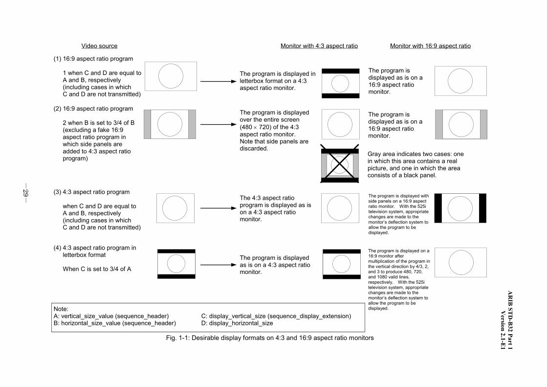
(1) 16:9 aspect ratio program
1 when C and D are equal toA and B, respectively(including cases in whichC and D are not transmitted)
The program isdisplayed as is on a16:9 aspect ratiomonitor.
Note:A: vertical_size_value (sequence_header) C: display_vertical_size (sequence_display_extension)B: horizontal_size_value (sequence_header) D: display_horizontal_size
Video source Monitor with 4:3 aspect ratio Monitor with 16:9 aspect ratio
(2) 16:9 aspect ratio program
2 when B is set to 3/4 of B(excluding a fake 16:9aspect ratio program inwhich side panels areadded to 4:3 aspect ratioprogram)
(3) 4:3 aspect ratio program
when C and D are equal toA and B, respectively(including cases in whichC and D are not transmitted)
(4) 4:3 aspect ratio program inletterbox format
When C is set to 3/4 of A
The program is displayed inletterbox format on a 4:3aspect ratio monitor.
The program is displayedas is on a 4:3 aspect ratiomonitor.
The 4:3 aspect ratioprogram is displayed as ison a 4:3 aspect ratiomonitor.
The program is displayed on a16:9 monitor aftermultiplication of the program inthe vertical direction by 4/3, 2,and 3 to produce 480, 720,and 1080 valid lines,respectively. With the 525itelevision system, appropriatechanges are made to themonitor’s deflection system toallow the program to bedisplayed.
The program is displayed withside panels on a 16:9 aspectratio monitor. With the 525itelevision system, appropriatechanges are made to themonitor’s deflection system toallow the program to bedisplayed.
Fig. 1-1: Desirable display formats on 4:3 and 16:9 aspect ratio monitors
ARIB STD-B32 Part 1 Version 2.1-E1
-30-
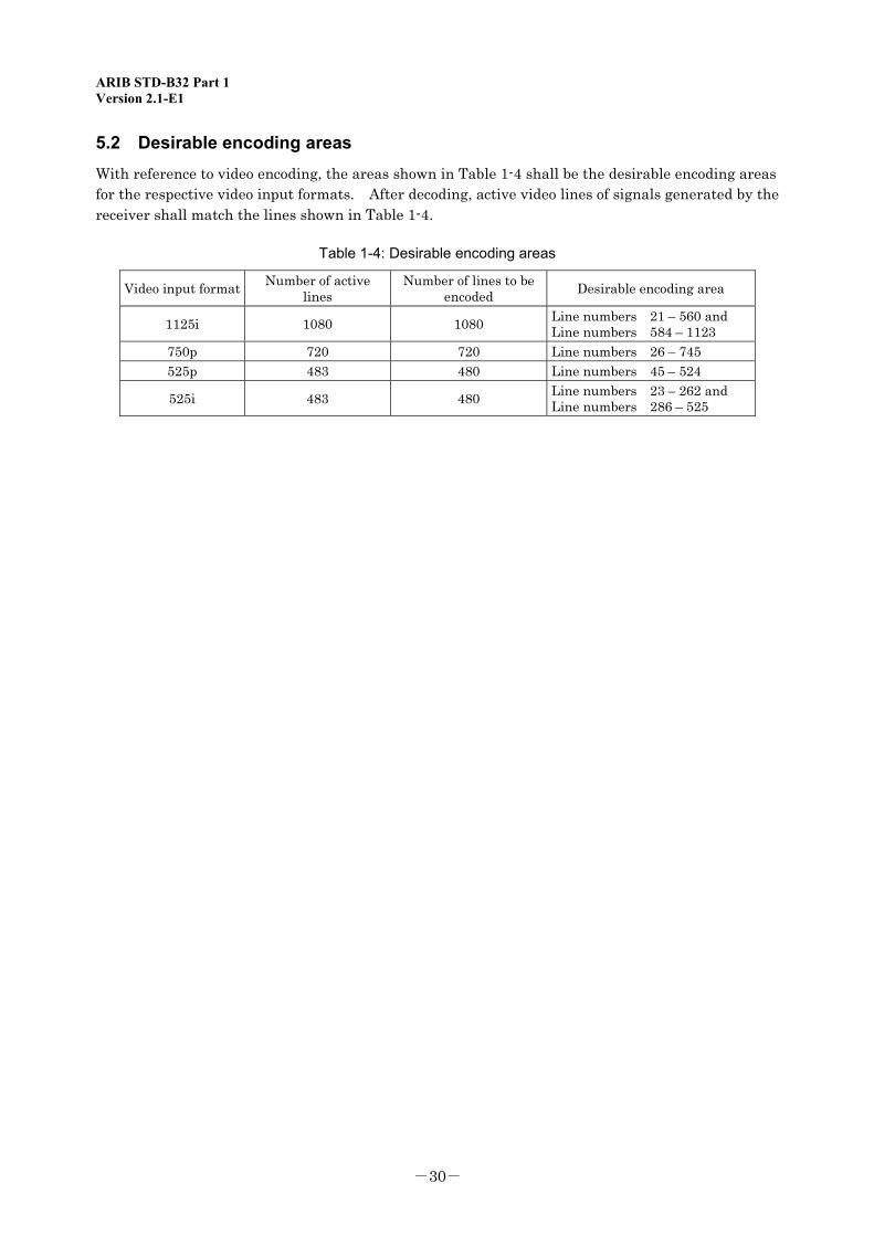
5.2 Desirable encoding areas With reference to video encoding, the areas shown in Table 1-4 shall be the desirable encoding areas for the respective video input formats. After decoding, active video lines of signals generated by the receiver shall match the lines shown in Table 1-4.
Table 1-4: Desirable encoding areas
Video input format Number of active lines
Number of lines to be encoded Desirable encoding area
1125i 1080 1080 Line numbers 21 – 560 and Line numbers 584 – 1123
750p 720 720 Line numbers 26 – 745 525p 483 480 Line numbers 45 – 524
525i 483 480 Line numbers 23 – 262 and Line numbers 286 – 525
ARIB STD-B32 Part 1 Appendix Version 2.1-E1
Appendix: Operating Guidelines

ARIB STD-B32 Part 1 Appendix Version 2.1-E1
<Blank Page>
ARIB STD-B32 Part 1 Appendix Version 2.1-E1
-31-
Appendix: Operating Guidelines
Chapter 1: General Terms
1.1 Objective The purpose of these guidelines is to present various recommendations concerning technical requirements for the practical implementation of video signals and video signal coding systems for digital terrestrial television, BS digital, and broadband CS digital broadcasting.
1.2 Scope This standard applies to video signals using PES packets among the various types of video signals that comply with the “Standard transmission system for digital broadcasting among standard television broadcasting and the like” (Ordinance). This standard also applies to digital terrestrial television, BS digital, and broadband CS digital broadcasts, unless otherwise specified.
1.3 References 1.3.1 Normative documents
(1) ISO/IEC 13818-2:2000 | ITU-T Rec. H.262: Information technology—Generic coding of moving pictures and associated audio information: Video (hereinafter referred to as “MPEG-2 Video Standard”)
(2) ISO/IEC 13818-1:2000 | ITU-T Rec. H.222: Information technology—Generic coding of moving pictures and associated audio information: Systems (hereinafter referred to as “MPEG-2 Systems Standard”)
1.4 Terminology 1.4.1 Abbreviations
CA Conditional Access CAT Conditional Access Table DTS Decoding Time-Stamp ECM Entitlement Control Message EMM Entitlement Management Message ES Elementary Stream GOP Group of Pictures HDTV High Definition Television (Note 1) NIT Network Information Table PAT Program Association Table PES Packetized Elementary Stream PID Packet Identifier PMT Program Map Table PSI Program Specific Information PTS Presentation Time-Stamp SDTV Standard Definition Television (Note 2) TMCC Transmission & Multiplexing Configuration Control TS Transport Stream
Note 1: In this standard, the term denotes “High Definition Television Broadcast” as defined in the ordinance.
Note 2: In this standard, the term denotes “Standard Definition Television Broadcast” as defined in the ordinance.

ARIB STD-B32 Part 1 Appendix Version 2.1-E1
-32-
<Blank Page>
ARIB STD-B32 Part 1 Appendix Version 2.1-E1
-33-
Chapter 2: Transmitting Sequence Header and Sequence End Code
2.1 Transmitting sequence header (sequence_header) sequence_header and sequence_extension (and sequence_display_extension if necessary) shall be transmitted immediately before the GOP header. If the GOP header is not transmitted, sequence_header and sequence_extension shall be transmitted immediately before I-picture data at the beginning of GOP.
2.2 Transmitting sequence end code (sequence_end_code) sequence_end_code shall be transmitted immediately after a single frame of video data has been transmitted.
Note: When a sequence_end_code is received on the receiver side, it is recommended that the freeze-frame of the video data received immediately before the sequence_end_code be displayed as the following video data is decoded and displayed. This permits continuous display of video data if the video data transmitted following the sequence_end_code is decoded and displayed without delay. It does not necessarily mean that the freeze-fram of video data is displayed continuously.

ARIB STD-B32 Part 1 Appendix Version 2.1-E1
-34-
<Blank Page>
ARIB STD-B32 Part 1 Appendix Version 2.1-E1
-35-
Chapter 3: Channel-hopping time
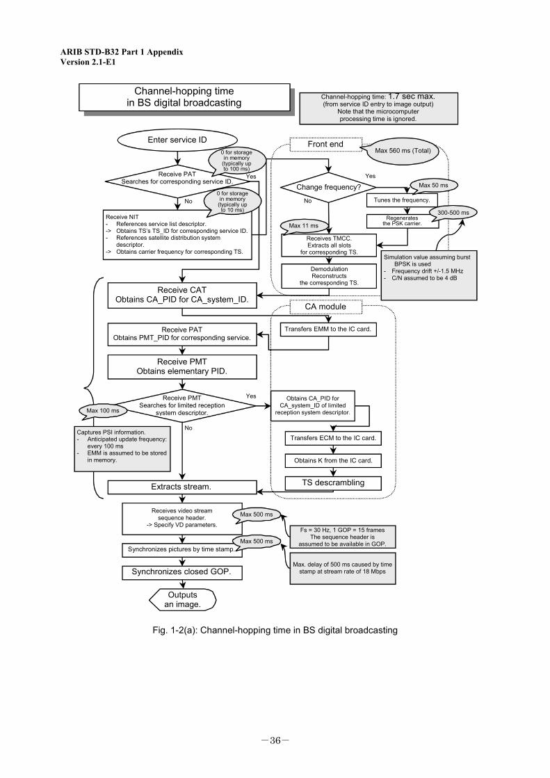
The following operation is recommended to keep channel-hopping time below a given duration: sequence_header shall be encoded at least every 500 ms, and the picture shall be updated in intra mode.
Note: The sequence_header that contains video format and other information, transmission frequency of intra mode picture, and delay at the buffer are among the video coding parameters related to channel-hopping time.
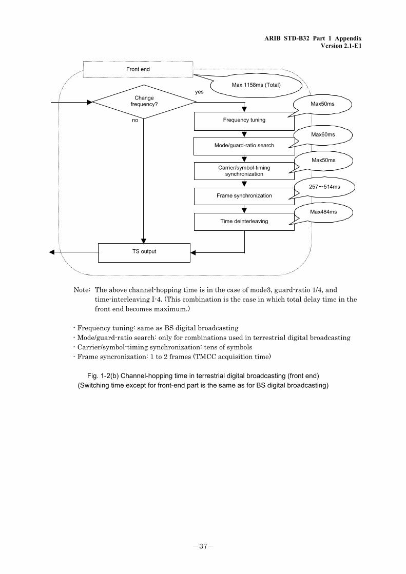
Fig. 1-2(a) shows a flowchart of various stages related to channel-hopping in BS digital broadcasting. Fig. 1-2(b) shows figures for terrestrial digital broadcasting. The channel-hopping time in terrestrial digital broadcasting is the same as for BS digital broadcasting, except for the front-end part. The channel-hopping time at the front-end part in terrestrial digital broadcasting is shown in Fig. 1-2(b) .
ARIB STD-B32 Part 1 Appendix Version 2.1-E1
-36-
Channel-hopping timein BS digital broadcasting
Enter service ID
Receive PATSearches for corresponding service ID.
0 for storagein memory
(typically upto 100 ms)
0 for storagein memory
(typically upto 10 ms)
Receive NIT- References service list descriptor.-> Obtains TS’s TS_ID for corresponding service ID.- References satellite distribution system
descriptor.-> Obtains carrier frequency for corresponding TS.
Receive CATObtains CA_PID for CA_system_ID.
Receive PATObtains PMT_PID for corresponding service.
Receive PMTObtains elementary PID.
Receive PMTSearches for limited reception
system descriptor.
Captures PSI information.- Anticipated update frequency:
every 100 ms- EMM is assumed to be stored
in memory.
Extracts stream.
Receives video streamsequence header.
-> Specify VD parameters.
Synchronizes pictures by time stamp.
Synchronizes closed GOP.
Outputsan image.
Yes
No
No
Yes
Max 100 ms
Max 500 ms
Max 500 ms
Max 11 ms
Channel-hopping time: 1.7 sec max.(from service ID entry to image output)
Note that the microcomputerprocessing time is ignored.
300-500 ms
Max 50 ms
Front endMax 560 ms (Total)
Change frequency?
Tunes the frequency.
Regeneratesthe PSK carrier.
Receives TMCC.Extracts all slots
for corresponding TS.
DemodulationReconstructs
the corresponding TS.
Simulation value assuming burstBPSK is used
- Frequency drift +/-1.5 MHz- C/N assumed to be 4 dB
CA module
Transfers EMM to the IC card.
Obtains CA_PID forCA_system_ID of limited
reception system descriptor.
Transfers ECM to the IC card.
Obtains K from the IC card.
TS descrambling
Fs = 30 Hz, 1 GOP = 15 framesThe sequence header is
assumed to be available in GOP.
Max. delay of 500 ms caused by timestamp at stream rate of 18 Mbps
Yes
No
Fig. 1-2(a): Channel-hopping time in BS digital broadcasting
ARIB STD-B32 Part 1 Appendix Version 2.1-E1
-37-
Frequency tuning
Carrier/symbol-timingsynchronization
Time deinterleaving
Mode/guard-ratio search
Changefrequency?
TS output
Front end
Max50ms
Max60ms
Max50ms
Frame synchronization257~514ms
Max484ms
yes
no
Max 1158ms (Total)
Note: The above channel-hopping time is in the case of mode3, guard-ratio 1/4, and
time-interleaving I-4. (This combination is the case in which total delay time in the front end becomes maximum.)
- Frequency tuning: same as BS digital broadcasting - Mode/guard-ratio search: only for combinations used in terrestrial digital broadcasting - Carrier/symbol-timing synchronization: tens of symbols - Frame syncronization: 1 to 2 frames (TMCC acquisition time)
Fig. 1-2(b) Channel-hopping time in terrestrial digital broadcasting (front end)
(Switching time except for front-end part is the same as for BS digital broadcasting)

ARIB STD-B32 Part 1 Appendix Version 2.1-E1
-38-
<Blank Page>
ARIB STD-B32 Part 1 Appendix Version 2.1-E1
-39-
Chapter 4: Seamless Switching
For seamless picture display by the receiver when switching between video formats, the following procedure is recommended for the transmitting and receiving sides:
4.1 Changing the number of active samples (1) Procedure on the transmitting side
The sequence is terminated at the operation switching point by sequence_end_code. A new number of samples is specified by the next sequence_header.
The first GOP of the new operation sequence sets the closed_gop flag in the GOP header. vbv_buffer_size remains unchanged after switching. This assures the seamlessness of PTS and DTS.
(2) Receiver operation The operating mode is specified by the pixel count parameter included in the received
sequence_header. The new operating mode is specified according to information included in the received sequence_header even if sequence_end_code is not received.
4.2 Changing picture aspect ratio with the 525i television system (1) Procedure on the transmitting side
The sequence is terminated at the operation switching point by sequence_end_code. A new aspect ratio is specified by the next sequence_header.
The first GOP of the new operation sequence sets the closed_gop flag in the GOP header. vbv_buffer_size remains unchanged after switching. This assures the seamlessness of PTS and DTS.
(2) Receiver operation The operating mode is specified by the aspect ratio parameter included in the received
sequence_header. The new operating mode is specified according to information included in the received sequence_header even if sequence_end_code is not received.
4.3 Changing bitrate (1) Procedure on the transmitting side
The variable bitrate mode is always used. (vbv_delay: 0xFFFF) sequence_end_code is not inserted at the transfer bitrate change point. vbv_buffer_size remains unchanged after this change. This assures the seamlessness of PTS and DTS.
(2) Receiver operation The receiver shall operate seamlessly by controlling the start of video and audio decoding
and output according to PTS or DTS included in the PES Header.
ARIB STD-B32 Part 1 Appendix Version 2.1-E1
-40-
Note: The transfer bitrate is varied on the transmitting side based on the above procedure. In this case, control shall be exercised so that the decoder’s buffer does not fail. Of the total delay arising between coding and decoding, the interval during which data passes through the buffer is expressed as the “buffer capacity/bitrate.” That is, when vbv_buffer_size remains constant, the above interval changes with a change in bitrate. As a result, when the interval increases, the decoder’s buffer enters the underflow state, in which case it takes more time for data to be received. Conversely, when the interval decreases, the buffer enters the overflow state. The buffer will fail if this transition in buffer state exceeds buffer capacity.
4.4 Video format switching method This section describes the procedure for transmitting and receiving sides to ensure seamless or near-normal display of pictures when switching between video stream formats (e.g., 1080i, 720p, 480p, 480i) for a specific service ID. To allow perfectly seamless switching, both transmitting and receiving sides shall be capable of seamless switching. However, it is possible to assume that either the transmitting or receiving side or neither is capable of seamless switching when broadcasting services begin. In this case, the procedure given in this section is recommended for video format switching, given the fact that both the transmitting and receiving sides can be switched independently to a perfectly seamless switching-capable system by displaying a freeze-frame or black frame screen – an approach that is less visually disruptive. Sections 4.4.1 and 4.4.2 respectively describe the procedure for the transmitting side that permits perfectly seamless switching and the simple procedure. However, there are also other methods positioned between both of the above. It is possible to make the transmitting side gradually capable of perfectly seamless switching in parallel with upgrading the system on the transmitting side. As an example, this section discusses the switching of three SDTV programs to one HDTV program. However, switching from HDTV to SDTV or switching between different formats (e.g., 480i <-> 480p, 1080i <-> 720p) can be handled the same way on both transmitting and receiving sides. When switching from any video format to another for a specific service ID, the video stream ES PID for the original format shall be changed after switching to another format. When switching from three SDTV programs to one HDTV program or vice versa, broadcasting stations intending to provide seamless display shall transmit the same number of PMTs that specify the same service_id as SDTV during HDTV broadcasting, and shall specify as HDTV’s ES_PID a unique value to distinguish it any PID of components broadcast when transmission of the new PMT starts. Moreover, both SDTV and HDTV PMTs shall contain the video decode control descriptor given in the ARB STD-B10. In this section, we temporarily specify the following values as service_id and ES_PID, by assuming that the above requirements are met:
SDTV 1 program: service_id = 01, ES_PID = 101 -> HDTV program: service_id = 01, ES_PID = 104
SDTV 2 program: service_id = 02, ES_PID = 102 -> HDTV program: service_id = 02, ES_PID = 104
SDTV 3 program: service_id = 03, ES_PID = 103 -> HDTV program: service_id = 03, ES_PID = 104
ARIB STD-B32 Part 1 Appendix Version 2.1-E1
-41-
4.4.1 Procedure for perfect seamless switching (method with which sequence_end_code is transmitted)
(1) Procedure on the transmitting side 1. Assume that switching between SDTV and HDTV occurs at time T1. The SDTV’s PMT shall
contain video_decode_control_descriptor (sequence_end_code_flag: 1, video_encode_format: 0100 (480i), 0011 (480p)).
2. Three SDTV encoders and one HDTV encoder synchronize PCR and PTS (or DTS) to ensure seamless PCR at the time of switching.
3. Transmission of the HDTV program’s PMT (ES_PID = 104) starts one second (standard time) before switching time T1. HDTV’s PMT shall contain video_decode_control_descriptor (sequence_end_code_flag: 1, and video_encode_format: 0001 (1080i), 0010 (720p)). (Note 1)
4. Transmission of the SDTV stream terminates immediately before the switching time as the end of GOP, and sequence_end_code is added at the end. (Note 2)
5. At switching time, the muliplexer halts TS multiplexing for SDTV and starts TS multiplexing for HDTV. The HDTV sequence_header shall be transmitted as soon as possible after the switching to the HDTV stream is complete. The HDTV sequence_header shall begin with GOP. The first GOP shall be treated as a “closed GOP”. Null data is multiplexed between the SDTV stream’s sequence_end_code and HDTV stream’s sequence_header_code. (Note 2)
Note 1: Timing at which new PMT is to be transmitted For broadcasts of free programs only, the receiver can handle program switching as long as
a new PMT is transmitted at least 0.5 second before switching time T1. Because the transmitting side is typically operated in units of exactly seconds, transmitting a new PMT one second before T1 shall be the standard. There are no problems with the receiver as long as transmission of a new PMT starts 0.5 to 2.0 seconds before the switching time.
For broadcasts of pay per view programs, if there are a number of keys subject to program switching, transmission of a new ECM two seconds before switching time may in certain cases be too late, given the IC card response time. However, if a new PMT is transmitted more than two seconds before switching time, an individual selecting the station at that timing will be unable to see any picture at all for a lengthy duration. Therefore, a new PMT shall be transmitted sometime between 0.5 and 2.0 seconds before the switching time. CAS operation shall be ensured (for example) by unifying keys or using temporal non-scrambling so that no inconvenience arises, even when station selection is made at this timing.
Note 2: Schedule control is performed in units of seconds at the broadcasting stations. This control timing does not generally coincide with GOP end timing, due to GOP length or the frame/field frequency of 59.94 Hz. Therefore, stream end and start timings come slightly before or after the control timing. The gap between the end of SDTV stream and the start of HDTV stream shall be sufficiently narrow to prevent underflow at the decoder on the receiving side.
ARIB STD-B32 Part 1 Appendix Version 2.1-E1
-42-
(2) Receiver operation (a) A seamless switching-capable receiver 1. The receiver obtains the new version of PMT. 2. The Demux is set up so that it feeds the ES_PID stream data of both SDTV and HDTV to the AV
decoder when the receiver (based on the contents of the PMT descriptor) finds that switching from SDTV to HDTV will occur and that sequence_end_code will be transmitted in a stream. However, note that SDTV and HDTV real data is not fed to the decoder at the same time, regardless of transmission timing. Instead, SDTV stream data is first stored in the buffer. HDTV stream data is stored in the buffer only when the storage of SDTV stream data is complete.
3. The video decoder displays a freeze-frame picture and mutes the audio upon it obtaining sequence_end_code.
4. The decoder performs the appropriate decoding through automatic tracking upon obtaining sequence_header of HDTV stream. When ready to output normal video and audio data, the decoder cancels video freeze-frame and audio muting. (To display pictures in an apparently seamless manner, the HDTV stream shall be received soon after the SDTV stream so that the buffer does not underflow. In this case, no freeze-frame picture is displayed. If the period between the end and start of the SDTV stream is not sufficiently short, and if the buffer underflows as a result, a freeze-frame picture is transmitted immediately before sequence_end_code is displayed.)
5. When the receiver finds that HDTV decoding has begun, the Demux only feeds HDTV’s ES_PID to the AV decoder.
(b) A seamless switching-incapable receiver 1. The receiver obtains the new version of PMT. 2. Freeze-frame or black frame is displayed and audio muted if, based on the contents of the PMT
descriptor (regardless of whether sequence_end_code is present), the receiver finds that switching from SDTV to HDTV will occur.
3. The video decoder halts SDTV decoding. 4. The Demux is set up to stop receiving streams with SDTV’s ES_PID and feeds streams with
HDTV’s ES_PID to the decoder buffer. 5. Using the host CPU to monitor the sequence_header monitor register of the video decoder, the
receiver awaits HDTV stream input. 6. When the decoder obtains HDTV stream sequence_header, it begins HDTV decoding. When
ready to output normal video and audio data, the decoder cancels video freeze-frame and audio muting.
Precaution: If a receiver is available that is not seamless switching-capable, but can display a freeze-frame picture upon reception of new PMT, it is preferable that a virtually flicker-free picture be transmitted even when the freeze-frame picture is displayed 0.5 second (delay at the buffer) or more before start of new PMT transmission.
ARIB STD-B32 Part 1 Appendix Version 2.1-E1
-43-
The null packet ismultiplexed in this portion.
SD-ENC1output
SD-ENC2output
SD-ENC3output
HD-ENCoutput
SD1 programPID=101
Transmitting side
SD2 programPID=102
SD3 programPID=103
SD4 programPID=104
(Standard time)New PMT
HD programSD1 – SD3 programs
Stream switching
Switching time T1sequence_end_code
-2sec -0.5sec
Period during which transmissionnew PSI can be started
1.5sec
SD1(SD2,SD3) programPID=101(102,103)
HD programSD1(SD2,SD3) program
HD programPID=104
Actual data is not output.
Actual data is not output.
The data is output from the encoderbut discarded by the multiplexer
-1sec
Freezing may occur.
SD1(SD2,SD3) programPID=101(102,103)
HD programSD1(SD2,SD3) program
HD programPID=104
Freeze-frameor black frame
Waiting for data from HD
The screen in unfrozen if this gapis controlled so as to be sufficientlysmall without causing the buffer tounderflow.
The data is output from the encoderbut discarded by the multiplexer
The data is output from the encoderbut discarded by the multiplexer
The data is output from the encoderbut discarded by the multiplexer
HD sequence_header
MUXoutput
Seamless switching-capablereceiver SD -> HD
DeMUXoutput
DECoutput
Seamless switching-incapablereceiver SD -> HD
DeMUXoutput
DECoutput
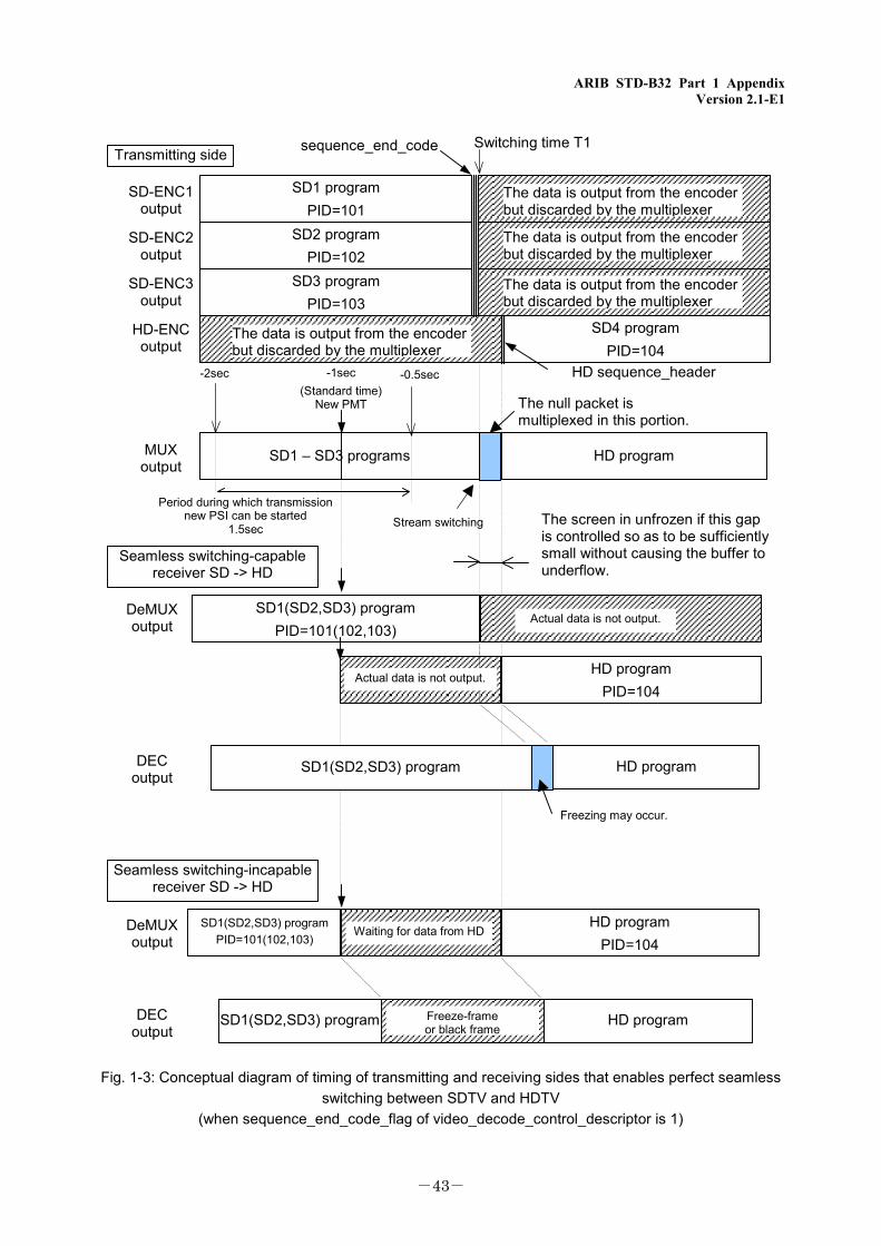
Fig. 1-3: Conceptual diagram of timing of transmitting and receiving sides that enables perfect seamless
switching between SDTV and HDTV (when sequence_end_code_flag of video_decode_control_descriptor is 1)
ARIB STD-B32 Part 1 Appendix Version 2.1-E1
-44-
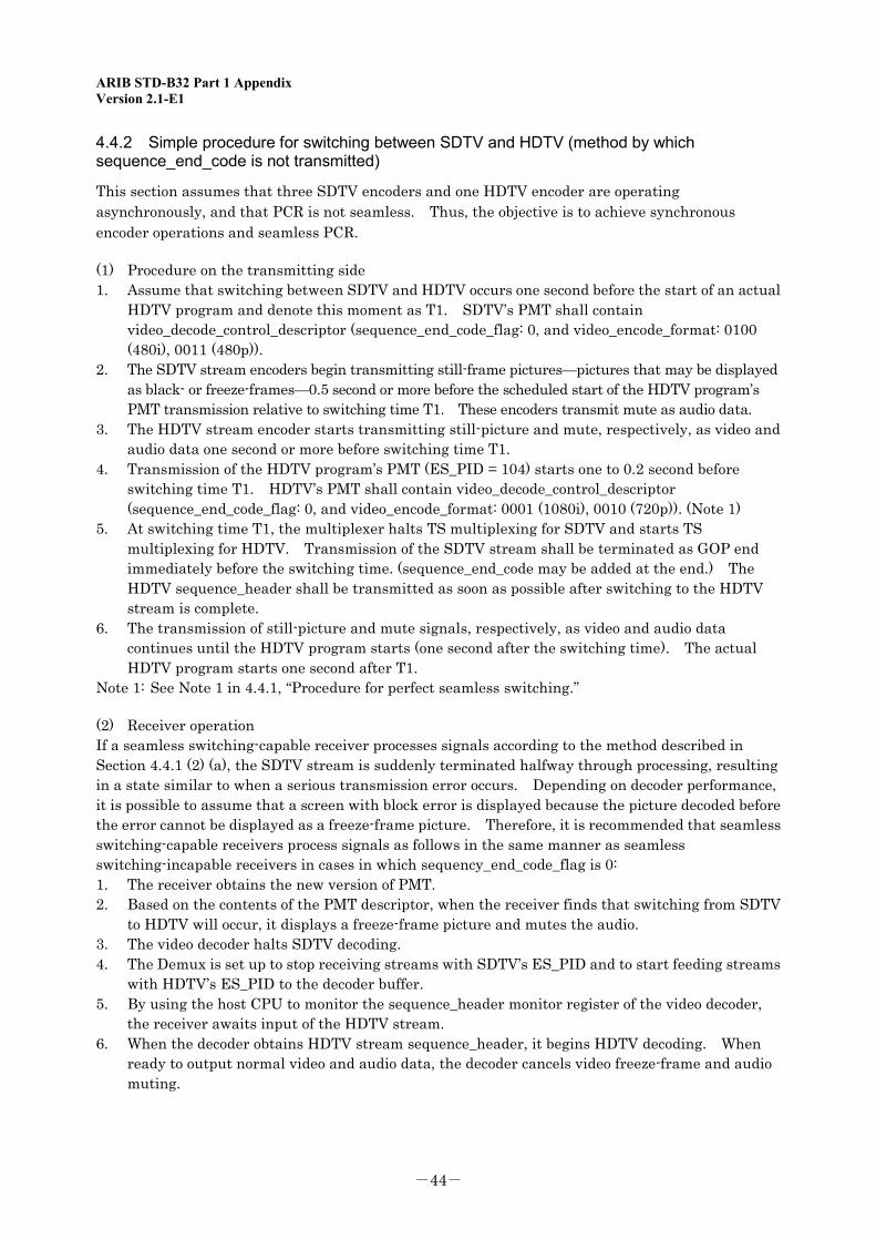
4.4.2 Simple procedure for switching between SDTV and HDTV (method by which sequence_end_code is not transmitted)
This section assumes that three SDTV encoders and one HDTV encoder are operating asynchronously, and that PCR is not seamless. Thus, the objective is to achieve synchronous encoder operations and seamless PCR.
(1) Procedure on the transmitting side 1. Assume that switching between SDTV and HDTV occurs one second before the start of an actual
HDTV program and denote this moment as T1. SDTV’s PMT shall contain video_decode_control_descriptor (sequence_end_code_flag: 0, and video_encode_format: 0100 (480i), 0011 (480p)).
2. The SDTV stream encoders begin transmitting still-frame pictures—pictures that may be displayed as black- or freeze-frames—0.5 second or more before the scheduled start of the HDTV program’s PMT transmission relative to switching time T1. These encoders transmit mute as audio data.
3. The HDTV stream encoder starts transmitting still-picture and mute, respectively, as video and audio data one second or more before switching time T1.
4. Transmission of the HDTV program’s PMT (ES_PID = 104) starts one to 0.2 second before switching time T1. HDTV’s PMT shall contain video_decode_control_descriptor (sequence_end_code_flag: 0, and video_encode_format: 0001 (1080i), 0010 (720p)). (Note 1)
5. At switching time T1, the multiplexer halts TS multiplexing for SDTV and starts TS multiplexing for HDTV. Transmission of the SDTV stream shall be terminated as GOP end immediately before the switching time. (sequence_end_code may be added at the end.) The HDTV sequence_header shall be transmitted as soon as possible after switching to the HDTV stream is complete.
6. The transmission of still-picture and mute signals, respectively, as video and audio data continues until the HDTV program starts (one second after the switching time). The actual HDTV program starts one second after T1.
Note 1: See Note 1 in 4.4.1, “Procedure for perfect seamless switching.”
(2) Receiver operation If a seamless switching-capable receiver processes signals according to the method described in Section 4.4.1 (2) (a), the SDTV stream is suddenly terminated halfway through processing, resulting in a state similar to when a serious transmission error occurs. Depending on decoder performance, it is possible to assume that a screen with block error is displayed because the picture decoded before the error cannot be displayed as a freeze-frame picture. Therefore, it is recommended that seamless switching-capable receivers process signals as follows in the same manner as seamless switching-incapable receivers in cases in which sequency_end_code_flag is 0: 1. The receiver obtains the new version of PMT. 2. Based on the contents of the PMT descriptor, when the receiver finds that switching from SDTV
to HDTV will occur, it displays a freeze-frame picture and mutes the audio. 3. The video decoder halts SDTV decoding. 4. The Demux is set up to stop receiving streams with SDTV’s ES_PID and to start feeding streams
with HDTV’s ES_PID to the decoder buffer. 5. By using the host CPU to monitor the sequence_header monitor register of the video decoder,
the receiver awaits input of the HDTV stream. 6. When the decoder obtains HDTV stream sequence_header, it begins HDTV decoding. When
ready to output normal video and audio data, the decoder cancels video freeze-frame and audio muting.
ARIB STD-B32 Part 1 Appendix Version 2.1-E1
-45-
HDActual main program
1.0 sec:Start of HD actual main program
HDActual main program
HDActual main
program
HD sequence_header
HD programPID=104
SD1program
SD2program
SD3program
0.5 second or more before thestart of new PMT transmission
SD1 – 3program
SD1 – 3program
SD1 – 3Video black- or freeze-
frame/mute
Period during which thereceiver’s decoding is abnormal500 ms (1 GOP) or less
-1.0sec
Period during whichreceiver obtains and
processes PSI
Period during which newPSI transmission starts
-0.2sec
-0.2sec
HDVideo
still-frame/mute
SD1 – 3Video black- orstill-frame/mute
SD1 – 3Video black- or still-frame/mute
SD1Video black- or still-frame/mute
SD1(SD2,SD3) programPID=101(102,103)
Waiting for datafrom HD
HDVideo
still-frame/mute
HDVideo
still-frame/mute
SD-ENC1output
SD-ENC2output
SD-ENC3output
HD-ENCoutput
Transmitting side
Stream switching
Switching time TI
The data is output from the encoderbut discarded by the multiplexer
The data is output from the encoderbut discarded by the multiplexer
The data is output from the encoderbut discarded by the multiplexer
The data is output from the encoderbut discarded by the multiplexer
MUXoutput
Seamless switching-capableand –incapable receivers
DeMUXoutput
DECoutput
SD2Video black- or still-frame/mute
SD3Video black- or still-frame/mute
Fig. 1-4: Conceptual diagram of timing of transmitting and receiving sides in simplified procedure switching for SDTV and HDTV (when sequence_end_code_flag of video_decode_control_descriptor is 0)
New PMT

ARIB STD-B32 Part 1 Appendix Version 2.1-E1
-46-
<Blank Page>
ARIB STD-B32 Part 1 Appendix Version 2.1-E1
-47-
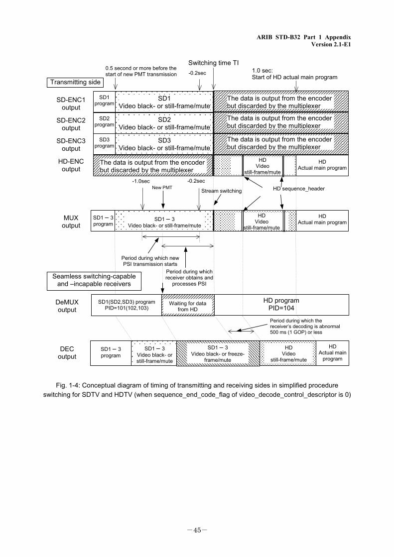
Chapter 5: Example of Encoding Film Materials
This chapter presents an example of encoding film materials by controlling the repeat_first_field, top_field_first, and progressive_frame flags of the picture layer. At this time, the same values are used for frame_rate_code and progressive_sequence of the sequence layer as for ordinary television pictures. With interlaced scanning, when the encoder detects 2-3 pull-down, it sums two temporally equal fields, encodes both as a progressive frame, and sets the flag that indicates that the field corresponding to the third field of the 2-3 pull-down system is identical to the first field. No video data for that field is transmitted. With progressive scanning, only 24 frames of video data are transmitted by setting the flag indicating that the first of 24 frames of film per second is displayed twice, the second three times, the third twice, the fourth three times, and so. At this time, the decoder can reproduce the 2-3 sequence when the repeat_first_field and top_field_first flags are set or reset as shown below. (See “Fig. 1-5: Example of encoding film materials.”)
Interlaced scanning When repeat_first_field = 0, the decoded picture consists of two fields. Conversely, when repeat_first_field = 1, the decoded picture consists of three fields. Whether the top or bottom field is displayed first is specified by top_field_first.
repeat_first_field top_field_first Decoded picture (fields) 0 1 top / bottom 1 1 top / bottom / top 0 0 bottom / top 1 0 bottom / top / bottom
Progressive scanning The number of times each frame is to be displayed is specified by the combination of repeat_first_field and top_field_first.
repeat_first_field top_field_first Number of times each frame is to be displayed 0 0 1 1 0 2 1 1 3
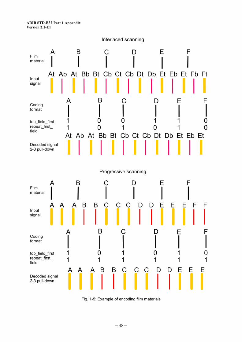
ARIB STD-B32 Part 1 Appendix Version 2.1-E1
-48-
Interlaced scanning
Film material
Input signal
Coding format
Decoded signal 2-3 pull-down
top_field_first repeat_first_ field
Film material
Input signal
Coding format
Decoded signal 2-3 pull-down
top_field_first repeat_first_ field
Progressive scanning
Fig. 1-5: Example of encoding film materials
ARIB STD-B32 Part 2 Version 2.1-E1
Part 2: Audio Signal and Coding System

ARIB STD-B32 Part 2 Version 2.1-E1
<Blank Page>
ARIB STD-B32 Part 2 Version 2.1-E1
-49-
Part 2: Audio Signal and Coding System
Contents
Chapter 1: General....................................................................................................................................51
1.1 Objective........................................................................................................................................51
1.2 Scope..............................................................................................................................................51
1.3 References .....................................................................................................................................51
1.3.1 Normative references..............................................................................................................51
1.3.2 Informative references............................................................................................................52
1.4 Terms and Abbreviations.............................................................................................................52
1.4.1 Abbreviations ..........................................................................................................................52
Chapter 2: Audio Input Signal .................................................................................................................53
Chapter 3: Audio Coding System .............................................................................................................55
Chapter 4: Audio Compression and Transmission Procedures..............................................................57
Chapter 5: Restrictions on Audio Coding Parameters............................................................................59
5.1 Input audio format .......................................................................................................................59
5.2 Audio coding system .....................................................................................................................59
5.2.1 Major parameters ...................................................................................................................59
5.2.2 Restrictions on MPEG-2 AAC ADTS coding parameters........................................................60
5.2.3 Detailed provisions regarding audio stream configuration and multiplexing ......................60
5.2.4 Operational provisions regarding compatibility with 2-channel stereo-capable receiver when multichannel stereo service is provided.......................................................................62
Annex: Operational Guidelines ................................................................................................................63
Chapter 1: General....................................................................................................................................63
1.1 Objective........................................................................................................................................63
1.2 Scope..............................................................................................................................................63
1.3 References .....................................................................................................................................63
ARIB STD-B32 Part 2 Version 2.1-E1
-50-
1.3.1 Normative references..............................................................................................................63
1.4 Terms and Abbreviations.............................................................................................................63
1.4.1 Abbreviations ..........................................................................................................................63
Chapter 2: Audio Quality Indication .......................................................................................................65
Chapter 3: Switching to New Audio Parameters ....................................................................................67
Interpretation: Considerations in Developing Operating Conditions ...................................................71
Appendix 1: CRC (Cyclic Redundancy Check) Processing Procedures for MPEG-2 AAC ADTS (Audio Data Transport Stream) ........................................................................................................75
Appendix 2: Overview of ISO/IEC 13818-1 AMD 6 (Related to AAC System Buffer) ..........................77
Appendix 3: Precautions associated with revision to ISO/IEC 13818-7:2003..................................78
Appendix 4: Precautions associated with implementation of MPEG-2 AAC standard...................79
ARIB STD-B32 Part 2 Version 2.1-E1
-51-
Chapter 1: General
1.1 Objective The purpose of this standard is to set specific parameters for audio signal and audio coding systems used in digital broadcasting among the ultrashort-wave (sound) broadcasting handled by broadcasting stations (except assisted satellite broadcasting) (hereinafter referred to as “terrestrial digital sound broadcasting”), digital broadcasting and high-definition television broadcasting among the various types of standard broadcasting handled by broadcasting stations (hereinafter referred to as “digital terrestrial television broadcasting”), ultrashort-wave (sound) broadcasting handled by broadcast satellite stations and broadcasting stations using frequency ranges greater than 2,630 MHz and less than or equal to 2,655 MHz (hereinafter referred to as “satellite digital sound broadcasting”), digital broadcasting among standard television broadcasting, high-definition television broadcasting, ultrashort-wave (sound) broadcasting, and data broadcasting handled by broadcast satellite stations using frequency ranges greater than 11.7 GHz and less than or equal to 12.2 GHz (hereinafter referred to as “BS digital broadcasting”), and standard television broadcasting, high-definition television broadcasting, ultrashort-wave (sound) broadcasting, and data broadcasting handled by broadcast satellite stations using frequency ranges greater than 12.2 GHz and less than or equal to 12.75 GHz and achieved through broadband transmission systems (hereinafter referred to as “broadband CS digital broadcasting”) that comply with the “Standard transmission system for digital broadcasting among standard TV broadcasting and the like” (Ministrerial ordinance of the Ministry of Internal Affairs and Communications, No. 26 of 2003).
1.2 Scope This standard applies to audio signals using PES packets among the various types of audio signals that comply with the “Standard transmission system for digital broadcasting among standard TV broadcasting and the like” (Ministrerial ordinance of the Ministry of Internal Affairs and Communications, No. 26 of 2003). This standard also applies commonly to all terrestrial digital sound broadcasting, digital terrestrial television broadcasting, satellite digital sound broadcasting, BS digital broadcasting, and broadband CS digital broadcasting, unless otherwise specified.
1.3 References 1.3.1 Normative references
The standard incorporates excerpts from the following documents:
(1) “Standard transmission system for digital broadcasting among standard TV broadcasting and the like (Ministrerial ordinance of the Ministry of Internal Affairs and Communications, No. 26 of 2003)” (hereinafter referred to as “ordinance”)
(2) “Defining compression and transmission procedures for a video signal using PES packets among the various types of video signals, and compression and transmission procedures for an audio signal using PES packets among the various types of audio signals (Notification of the Ministry of Internal Affairs and Communications, No. 38 of 2003)” (hereinafter referred to as “notification”)
(3) ISO/IEC 13818-7:2003 Information technology—Generic coding of moving pictures and associated audio information: Advanced Audio Coding
ARIB STD-B32 Part 2 Version 2.1-E1
-52-
(4) ISO/IEC 13818-7:2003/AMD 1:2004 Information technology—Generic coding of moving pictures and associated audio information: Advanced Audio Coding AMENDMENT 1: Embedding of bandwidth extension
(the above mentioned standards (3) and (4) are hereinafter referred to as “MPEG-2 AAC Standard”)
1.3.2 Informative references
(1) “Receiver for digital broadcasting ARIB standard (desirable specifications)” ARIB STD-B21. 1.4 Terms and Abbreviations 1.4.1 Abbreviations
AAC: Advanced Audio Coding ADTS: Audio Data Transport Stream CPE: Channel Pair Element CRC: Cyclic Redundancy Check DSE: Data Stream Element LC: Low Complexity LFE: Low Frequency Enhancement MPEG: Moving Picture Experts Group PCE: Program Configuration Element SBR Spectral Band Replication SCE: Single Channel Element
ARIB STD-B32 Part 2 Version 2.1-E1
-53-
Chapter 2: Audio Input Signal
(1) The sampling frequency for audio signals shall be 32 kHz, 44.1 kHz, or 48 kHz. (2) To configure stereophonic signals (consisting of two or more audio signals to achieve a
three-dimensional reproduction of sound), the sampling timing for all signals shall be the same. (3) The number of quantization bits for the input signal shall be 16 or more. (4) The maximum number of audio input channels shall be five, in addition to the channel used to
enhance low frequencies. (Ordinance)

ARIB STD-B32 Part 2 Version 2.1-E1
-54-
<Blank Page>
ARIB STD-B32 Part 2 Version 2.1-E1
-55-
Chapter 3: Audio Coding System
Audio signals shall be coded by a combination of time-frequency transform coding (in which the input signal is transformed into frequency components by modified discrete cosine transform, and in which the amount of information is reduced by using the decrease in energy deviation of frequency components) and psychoacoustic weighted bit assignment (in which codes are weighted to minimize signal degradation in the frequency range that is readily perceived by humans). Audio compression and transmission procedures shall comply with the notification separately issued by the Minister of Internal Affairs and Communications. See chapter 4.
(Ordinance)

ARIB STD-B32 Part 2 Version 2.1-E1
-56-
<Blank Page>
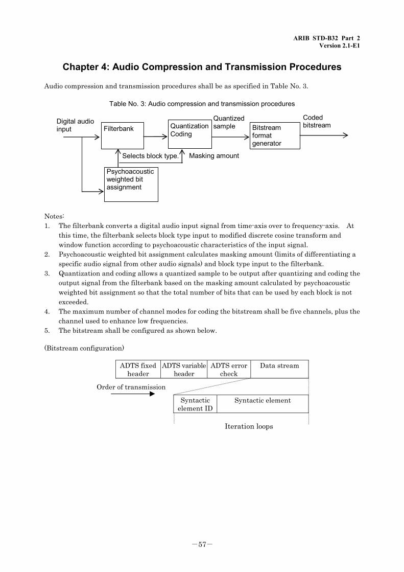
ARIB STD-B32 Part 2 Version 2.1-E1
-57-
Chapter 4: Audio Compression and Transmission Procedures
Audio compression and transmission procedures shall be as specified in Table No. 3.
Table No. 3: Audio compression and transmission procedures
Masking amount Selects block type.
Coded bitstream
Quantized sample Filterbank Bitstream
format generator
Psychoacoustic weighted bit assignment
Digital audio input Quantization
Coding
Notes: 1. The filterbank converts a digital audio input signal from time-axis over to frequency-axis. At
this time, the filterbank selects block type input to modified discrete cosine transform and window function according to psychoacoustic characteristics of the input signal.
2. Psychoacoustic weighted bit assignment calculates masking amount (limits of differentiating a specific audio signal from other audio signals) and block type input to the filterbank.
3. Quantization and coding allows a quantized sample to be output after quantizing and coding the output signal from the filterbank based on the masking amount calculated by psychoacoustic weighted bit assignment so that the total number of bits that can be used by each block is not exceeded.
4. The maximum number of channel modes for coding the bitstream shall be five channels, plus the channel used to enhance low frequencies.
5. The bitstream shall be configured as shown below.
(Bitstream configuration)
ADTS fixedheader
ADTS variableheader
ADTS errorcheck
Data stream
Order of transmission
Syntacticelement ID
Syntactic element
Iteration loops

ARIB STD-B32 Part 2 Version 2.1-E1
-58-
Notes: 1. The ADTS fixed header consists of synchronization and audio coded information defined in
ISO/IEC 13818-7. 2. The ADTS variable header consists of audio coded information defined in ISO/IEC 13818-7. 3. ADTS error check consists of error detection information. 4. The data stream consists of audio data coded according to ISO/IEC 13818-7. 5. The syntactic element ID indicates the type of syntactic element that follows this ID or end of
the data stream. 6. The syntactic element consists of various components of audio data coded according to ISO/IEC
13818-7. It is iterated the number of times specified in the ADTS variable header. (Ordinance)
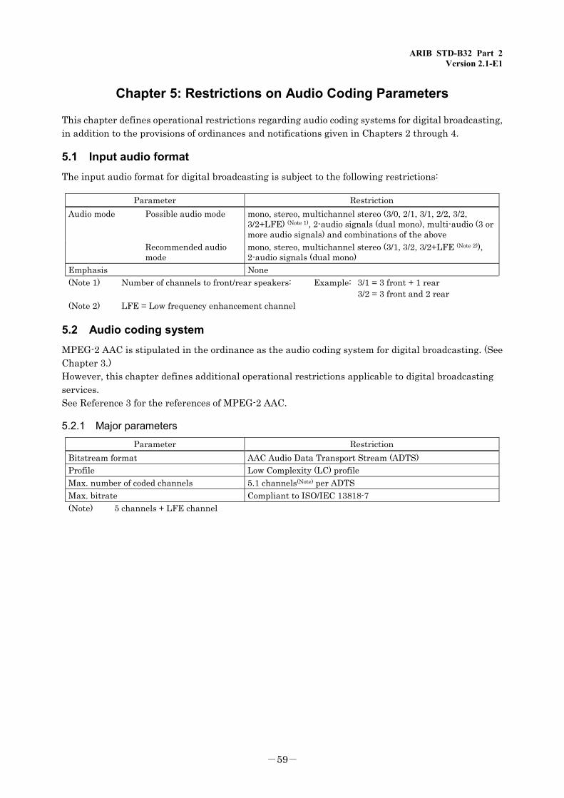
ARIB STD-B32 Part 2 Version 2.1-E1
-59-
Chapter 5: Restrictions on Audio Coding Parameters
This chapter defines operational restrictions regarding audio coding systems for digital broadcasting, in addition to the provisions of ordinances and notifications given in Chapters 2 through 4.
5.1 Input audio format The input audio format for digital broadcasting is subject to the following restrictions:
Parameter Restriction Audio mode Possible audio mode mono, stereo, multichannel stereo (3/0, 2/1, 3/1, 2/2, 3/2,
3/2+LFE) (Note 1), 2-audio signals (dual mono), multi-audio (3 or more audio signals) and combinations of the above
Recommended audio mode
mono, stereo, multichannel stereo (3/1, 3/2, 3/2+LFE (Note 2)), 2-audio signals (dual mono)
Emphasis None (Note 1) Number of channels to front/rear speakers: Example: 3/1 = 3 front + 1 rear
3/2 = 3 front and 2 rear (Note 2) LFE = Low frequency enhancement channel
5.2 Audio coding system MPEG-2 AAC is stipulated in the ordinance as the audio coding system for digital broadcasting. (See Chapter 3.) However, this chapter defines additional operational restrictions applicable to digital broadcasting services. See Reference 3 for the references of MPEG-2 AAC.
5.2.1 Major parameters
Parameter Restriction Bitstream format AAC Audio Data Transport Stream (ADTS) Profile Low Complexity (LC) profile Max. number of coded channels 5.1 channels(Note) per ADTS Max. bitrate Compliant to ISO/IEC 13818-7 (Note) 5 channels + LFE channel
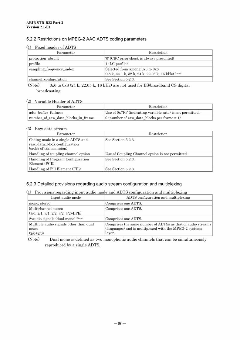
ARIB STD-B32 Part 2 Version 2.1-E1
-60-
5.2.2 Restrictions on MPEG-2 AAC ADTS coding parameters
(1) Fixed header of ADTS Parameter Restriction
protection_absent ‘0’ (CRC error check is always presented) profile 1 (LC profile) sampling_frequency_index Selected from among 0x3 to 0x8
(48 k, 44.1 k, 32 k, 24 k, 22.05 k, 16 kHz) (note) channel_configuration See Section 5.2.3. (Note) 0x6 to 0x8 (24 k, 22.05 k, 16 kHz) are not used for BS/broadband CS digital
broadcasting.
(2) Variable Header of ADTS Parameter Restriction
adts_buffer_fullness Use of 0x7FF (indicating variable rate) is not permitted. number_of_raw_data_blocks_in_frame 0 (number of raw_data_blocks per frame = 1)
(3) Raw data stream Parameter Restriction
Coding mode in a single ADTS and raw_data_block configuration (order of transmission)
See Section 5.2.3.
Handling of coupling channel option Use of Coupling Channel option is not permitted. Handling of Program Configuration Element (PCE)
See Section 5.2.3.
Handling of Fill Element (FIL) See Section 5.2.3.
5.2.3 Detailed provisions regarding audio stream configuration and multiplexing
(1) Provisions regarding input audio mode and ADTS configuration and multiplexing Input audio mode ADTS configuration and multiplexing
mono, stereo Comprises one ADTS. Multichannel stereo (3/0, 2/1, 3/1, 2/2, 3/2, 3/2+LFE)
Comprises one ADTS.
2-audio signals (dual mono) (Note) Comprises one ADTS. Multiple audio signals other than dual mono (2/0+2/0)
Comprises the same number of ADTSs as that of audio streams (languages) and is multiplexed with the MPEG-2 systems layer.
(Note) Dual mono is defined as two monophonic audio channels that can be simultaneously reproduced by a single ADTS.
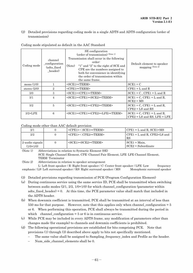
ARIB STD-B32 Part 2 Version 2.1-E1
-61-
(2) Detailed provisions regarding coding mode in a single ADTS and ADTS configuration (order of transmission)
Coding mode stipulated as default in the AAC Standard
Coding mode
channel _configuration
(adts_fixed _header)
SE configuration (order of transmission) (Note 1)
Transmission shall occur in the following order:
(Note) “1” and “2” to the right of SCE and CPE are the numbers assigned to both for convenience in identifying the order of transmission within the same frame.
Default element to speaker mapping (Note 2)
mono (1/0) 1 <SCE1><TERM> SCE1 = C stereo (2/0) 2 <CPE1><TERM> CPE1 = L and R
3/0 3 <SCE1><CPE1><TERM> SCE1 = C , CPE1 = L and R 3/1 4 <SCE1><CPE1><SCE2><TERM> SCE1 = C, CPE1 = L and R,
SCE2 = MS 3/2 5 <SCE1><CPE1><CPE2><TERM> SCE1 = C, CPE1 = L and R,
CPE2 = LS and RS 3/2+LFE 6 <SCE1><CPE1><CPE2><LFE><TERM> SCE1 = C, CPE1 = L and R,
CPE2 = LS and RS, LFE = LFE
Coding mode other than AAC default provision 2/1 0 <CPE1><SCE1><TERM> CPE1 = L and R, SCE1=MS 2/2 0 <CPE1><CPE2><TERM> CPE1 = L and R, CPE2=LS and
RS 2-audio signals
(1/0+1/0) 0 <SCE1><SCE2><TERM> SCE1 = Main,
SCE2 = Subordinate (Note 1) Abbreviations in relation to Syntactic Element (SE) SCE: Single Channel Element, CPE: Channel Pair Element, LFE: LFE Channel Element, TERM: Terminator (Note 2) Abbreviations in relation to speaker arrangement L: Left front speaker / R: Right front speaker / C: Center front speaker / LFE: Low frequency emphasis / LS: Left surround speaker / RS: Right surround speaker / MS: Monophonic surround speaker
(3) Detailed provisions regarding transmission of PCE (Program Configuration Element) (a) During continuous service using the same service ID, PCE shall be transmitted when switching
between audio modes (2/1, 2/2, 1/0+1/0) for which channel_configuration (parameter within adts_fixed_header) = 0. At this time, the PCE parameter value shall match that included in the ADTS header.
(b) When downmix coefficient is transmitted, PCE shall be transmitted at an interval of less than 550 ms for that purpose. However, note that this applies only when channel_configuration = 5 or 6. When performing this operation, PCE shall always be transmitted during the period in which channel_configuration = 5 or 6 is in continuous service.
(c) While PCE may be included in every ADTS frame, any modification of parameters other than changes made (for example) to channels and downmix coefficients is prohibited.
(d) The following operational provisions are established for bits comprising PCE. Note that provisions (1) through (3) described above apply to bits not specifically mentioned. − The same value shall be assigned to Sampling_frequency_index and Profile as the header. − Num_side_channel_elements shall be 0.
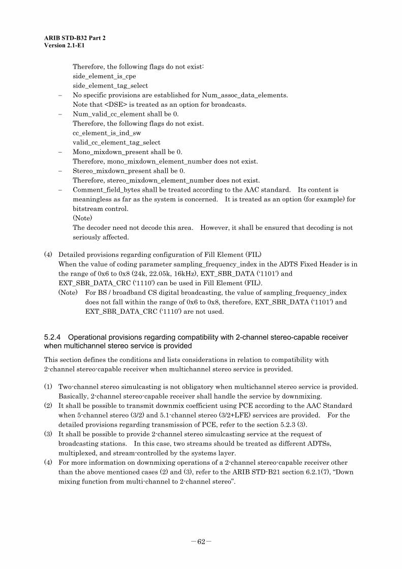
ARIB STD-B32 Part 2 Version 2.1-E1
-62-
Therefore, the following flags do not exist: side_element_is_cpe side_element_tag_select − No specific provisions are established for Num_assoc_data_elements. Note that <DSE> is treated as an option for broadcasts. − Num_valid_cc_element shall be 0. Therefore, the following flags do not exist. cc_element_is_ind_sw valid_cc_element_tag_select − Mono_mixdown_present shall be 0. Therefore, mono_mixdown_element_number does not exist. − Stereo_mixdown_present shall be 0. Therefore, stereo_mixdown_element_number does not exist. − Comment_field_bytes shall be treated according to the AAC standard. Its content is
meaningless as far as the system is concerned. It is treated as an option (for example) for bitstream control.
(Note) The decoder need not decode this area. However, it shall be ensured that decoding is not
seriously affected.
(4) Detailed provisions regarding configuration of Fill Element (FIL) When the value of coding parameter sampling_frequency_index in the ADTS Fixed Header is in
the range of 0x6 to 0x8 (24k, 22.05k, 16kHz), EXT_SBR_DATA (‘1101’) and EXT_SBR_DATA_CRC (‘1110’) can be used in Fill Element (FIL). (Note) For BS / broadband CS digital broadcasting, the value of sampling_frequency_index
does not fall within the range of 0x6 to 0x8, therefore, EXT_SBR_DATA (‘1101’) and EXT_SBR_DATA_CRC (‘1110’) are not used.
5.2.4 Operational provisions regarding compatibility with 2-channel stereo-capable receiver when multichannel stereo service is provided
This section defines the conditions and lists considerations in relation to compatibility with 2-channel stereo-capable receiver when multichannel stereo service is provided.
(1) Two-channel stereo simulcasting is not obligatory when multichannel stereo service is provided. Basically, 2-channel stereo-capable receiver shall handle the service by downmixing.
(2) It shall be possible to transmit downmix coefficient using PCE according to the AAC Standard when 5-channel stereo (3/2) and 5.1-channel stereo (3/2+LFE) services are provided. For the detailed provisions regarding transmission of PCE, refer to the section 5.2.3 (3).
(3) It shall be possible to provide 2-channel stereo simulcasting service at the request of broadcasting stations. In this case, two streams should be treated as different ADTSs, multiplexed, and stream-controlled by the systems layer.
(4) For more information on downmixing operations of a 2-channel stereo-capable receiver other than the above mentioned cases (2) and (3), refer to the ARIB STD-B21 section 6.2.1(7), “Down mixing function from multi-channel to 2-channel stereo”.

ARIB STD-B32 Part 2 Annex Version 2.1-E1
Annex: Operational Guidelines

ARIB STD-B32 Part 2 Annex Version 2.1-E1
<Blank Page>
ARIB STD-B32 Part 2 Annex Version 2.1-E1
-63-
Annex: Operational Guidelines
Chapter 1: General
1.1 Objective The purpose of these guidelines is to present recommended technical requirements for practical operations regarding audio signal and audio coding systems for terrestrial digital sound broadcasiting, digital terrestrial television broadcasiting, satellite digital sound broadcasiting, BS digital broadcasiting, and broadband CS digital broadcasting.
1.2 Scope These guidelines apply to audio signals using PES packets among the various types of audio signals that comply with the “Standard transmission system for digital broadcasting among standard TV broadcasting and the like” (Ordinance). These guidelines also apply commonly to all terrestrial digital sound broadcasting, digital terrestrial television broadcasting, satellite digital sound broadcasting, BS digital broadcasting, and broadband CS digital broadcasting,unless otherwise specified.
1.3 References 1.3.1 Normative references
(1) ISO/IEC 13818-7:2003 Information technology—Generic coding of moving pictures and associated audio information: Advanced Audio Coding
(2) ISO/IEC 13818-7 2003/AMD 1:2004 Information technology—Generic coding of moving pictures and associated audio information: Advanced Audio Coding AMENDMENT 1: Embedding of bandwidth extension
(the above mentioned standards (1) and (2) are hereinafter referred to as “MPEG-2 AAC Standard”)
(3) ISO/IEC 13818-1:2000 | ITU-T Rec. H.222: Information technology—Generic coding of moving pictures and associated audio information: Systems (hereinafter referred to as “MPEG-2 Systems Standard”)
1.4 Terms and Abbreviations 1.4.1 Abbreviations
AAC: Advanced Audio Coding ADTS: Audio Data Transport Stream CCE: Coupling Channel Element CPE: Channel Pair Element CRC: Cyclic Redundancy Check ICS: Individual Channel Stream LC: Low Complexity LFE: Low Frequency Element MPEG: Moving Picture Experts Group SCE: Single Channel Element SSR: Scalable Sampling Rate PCE: Program Configuration Element PTS: Program Time Stamp

ARIB STD-B32 Part 2 Annex Version 2.1-E1
-64-
<Blank Page>
ARIB STD-B32 Part 2 Annex Version 2.1-E1
-65-
Chapter 2: Audio Quality Indication
A quality indicator (“quality_indicator”) is assigned as an audio component descriptor for multiplexing systems. It can be used to transmit and indicate audio quality signals. The quality indicator shall be transmitted in accordance with the quality of an AAC coding stream that meets the audio quality criteria. Two bits are assigned to the quality indicator so that audio quality can be classified into up to four different groups. With BS digital broadcasting, it is assumed that two types of audio quality will be available: one equivalent to B mode in conventional satellite standard television broadcasting (analog); and other type such as A mode. Conversely, terrestrial digital television and terrestrial digital audio broadcasting requires the use of sampling frequencies below 32 kHz. Therefore, three audio quality indications are assumed to be available: the two types of audio quality mentioned above, and one that is limited compared with the other two. Table 2-1 lists the quality indicator assignments and correspondence between the content of quality indicators and coded audio quality. Mode 1 represents the high audio quality equivalent to B mode available in the conventional satellite standard television broadcasting. The expected bitrate for 2-channel stereo transmission (to be used for the time being), is shown for reference purposes in the table, based on the results of tests including a subjective assessment test. Also note that mode 2 represents standard audio quality that is not classified as mode 1. The bitrate available when applying the audio quality criteria in the ITU-R standard is shown for reference purposes. These reference values have been introduced based on the tests using a properly adjusted encoder that can handle off-line processing. It will be necessary to check these results with a practical real-time encoder for broadcasting. Conversely, it is expected that advances in encoder technology that occur at the start of broadcasting and later will ensure that specified audio quality criteria are met at lower bitrates than the reference values. In the meantime, the main purpose of mode 3 is to inform viewers that this mode offers limited audio quality compared to modes 1 and 2. Therefore, no quantitative guidelines are established. Instead, it is assumed that broadcasters will choose whether to offer this mode, based on agreed upon rules. Note that mode 3 will not be used for BS or broadband CS digital broadcasting for the reasons mentioned above.
ARIB STD-B32 Part 2 Annex Version 2.1-E1
-66-
Table 2-1: Quality indicator assignments and coded audio qualities
Quality indicator
Audio quality name (Note 1) Coded audio quality criterion Remarks
00 Reserve 01 Mode 1 Audio quality equivalent to B mode
available in conventional satellite standard television broadcasting
Reference bitrate 192 to 256 kbps/stereo or more (Note 2)
10 Mode 2 Audio quality (Note 3) other than mode 1 that is not classified in mode 3
11 Mode 3 Mode with limited audio quality compared to modes 1 and 2
It is assumed that broadcasters will choose whether to offer this mode at their own discretion based on agreed upon rules. (ex. Sampling frequency below 32 kHz) This mode is not used in BS or broadband CS digital broadcasting.
(Note 1) In this table, audio quality is referred to as mode 1, 2, or 3 audio quality for the sake of convenience. Note that audio quality may be referred to as something else when actual services are provided. (Note 2) Mode 1 audio quality will be offered at 192 to 256 kbps/stereo or more for the following reasons:
Following subjective assessment tests conducted by ARIB in June 1998, we can say that the following holds true:
The higher the bitrate, the better the audio quality. The audio quality available with 192 kbps/stereo is barely distinguishable from the original sound.
It is appropriate to examine the possible application of a bitrate that is approximately 1.5 times that used for broadcasting, given the relationship of codec bitrate for broadcasting and material transmission (MPEG-1 layer 2 coding) in the Rec. ITU-R.
(Note 3) The reference bitrate is as shown below when applying the following audio quality criterion:
Audio quality criterion Reference bitrate Audio quality for digital broadcasting given in ITU-R
144 kbps/stereo or more
ARIB STD-B32 Part 2 Annex Version 2.1-E1
-67-
Chapter 3: Switching to New Audio Parameters
This provision applies to switches made to audio stream parameters within the same service ID to be transmitted from local station. More specifically, this provision applies the following parameters: Sampling frequency Bitrate Channel configuration Audio mode
The followings are taken into account with regard to this provision: A switch will be made to any of the audio parameters with at least 0.5 seconds of mute input to
the audio encoder. The future potential reduction of mute time willl be considered as well. The specifics of implementing the audio encoder are unspecified. The audio decoder shall have buffer capacity sufficient for the maximum number of channels to
be handled by that decoder. Switch to any of the audio parameters will be made by controlling the entire buffer. However, note that control and monitoring of the buffer capacity stipulated by that parameter (e.g., overflow, underflow) is performed under a steady-state condition.
Provision regarding receiver − The buffer may underflow. − A signal for mute is output if the buffer becomes empty. (If necessary, the audio level will
start fading out immediately before the buffer becomes empty.) − After the buffer is empty, decoding will resume when the predetermined coded audio data is
received.
(1) Switching sampling frequency When the sampling frequency is altered, the decoder will change its reference clock. Therefore, a transient and unstable condition occurs for a specific period of time. Since there is some question as to whether inserting 0.5 seconds of mute is sufficient, caution shall be exercised during operation.
(2) Switching bitrate It is possible to ensure seamless changes in bitrate by appropriately controlling the buffer at the encoder side. If it is possible that the buffer may not be properly controlled, due (for example) to change in coding delay caused by switch to bitrate, it is necessary to abide by the rules indicated in the next section, “(3) Switching to other parameters.”
ARIB STD-B32 Part 2 Annex Version 2.1-E1
-68-
(3) Switching to other parameters (a) The encoder waits until there is no more stream data stored in the encoder and decoder buffers.
Then, the encoder changes the target audio parameter and resumes encoding. After encoding resumes, the preset amount of coded audio stream data is stored in the encoder buffer. Finally, audio stream data is sent to the decoder.
Since stream data is transmitted using MPEG-2 Systems, PTS shall be added to the first frame of stream data encoded after any interruption. Also note that to ensure that the decoder can find that a change has been made to a parameter, there shall be a gap of at least three frames between the PTS of the stream (stream introduced on the assumption that it occurs after the stream with the previous parameter) and the PTS added to the stream that is actually transmitted.
(b) The decoder halts decoding and mutes the audio when no audio stream data is found in the decoder input buffer. If audio stream data remains in the decoder input buffer and if the ADTS (Audio_Data_Transport_Stream) frame header is found, the decoder waits until the amount of stream data specified by the adts_buffer_fullness field is stored in the input buffer and resumes decoding based on the new audio parameter information.
The decoder cancels audio muting and outputs decoded audio signals when this signal is requested (at any time after completion of decoding of two frames because overlapping occurs.)
However, note that streams generated by the above model are in practice transmitted through the MPEG-2 Systems, and that the decoder performs buffer control using system buffer and PTS. In this case, the decoder may not always be able to find that the decoder buffer is empty, despite the assumption made above at the elementary stream level. Under such circumstances, the decoder can determine that a change has been made to a parameter by finding that streams are not in succession based on the PTS added to the first audio frame after parameter change and also based on system clock information.
To facilitate the comprehension of audio parameter change sequence, Figs. 3-1 and 3-2, respectively, show the flow diagram and the timing diagram for switching audio parameters.
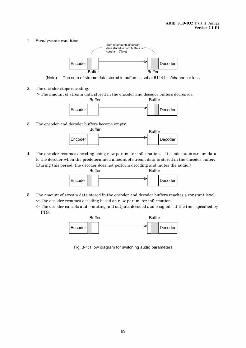
ARIB STD-B32 Part 2 Annex Version 2.1-E1
-69-
1. Steady-state condition
Buffer
Encoder
Buffer
Decoder
Sum of amounts of streamdata stored in both buffers isconstant. (Note)
(Note) The sum of stream data stored in buffers is set at 6144 bits/channel or less.
2. The encoder stops encoding. -> The amount of stream data stored in the encoder and decoder buffers decreases.
Buffer
Encoder
Buffer
Decoder
3. The encoder and decoder buffers become empty. Buffer Buffer
Encoder Decoder
4. The encoder resumes encoding using new parameter information. It sends audio stream data to the decoder when the predetermined amount of stream data is stored in the encoder buffer.
(During this period, the decoder does not perform decoding and mutes the audio.) Buffer
Encoder
Buffer
Decoder
5. The amount of stream data stored in the encoder and decoder buffers reaches a constant level. -> The decoder resumes decoding based on new parameter information. -> The decoder cancels audio muting and outputs decoded audio signals at the time specified by
PTS. Buffer
Encoder
Buffer
Decoder
Fig. 3-1: Flow diagram for switching audio parameters
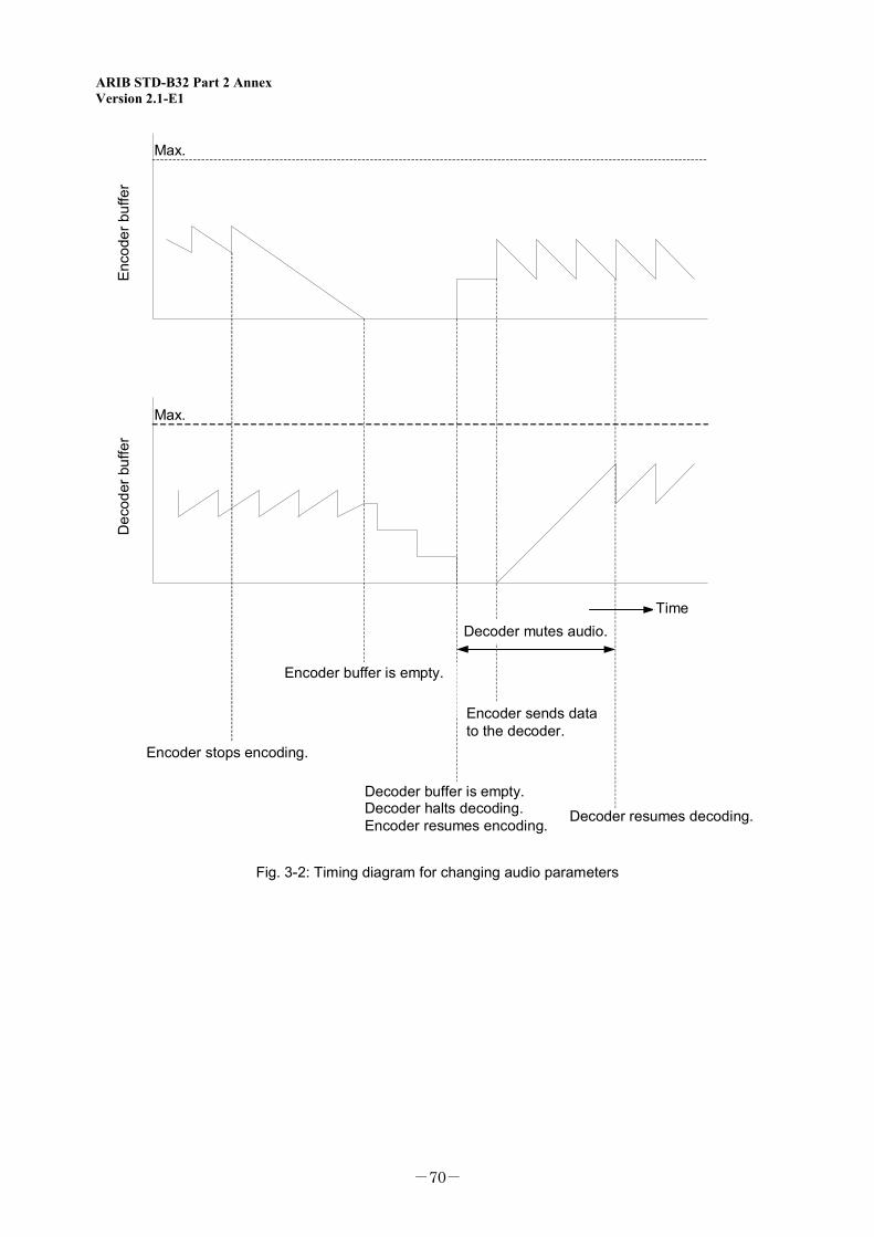
ARIB STD-B32 Part 2 Annex Version 2.1-E1
-70-
Max.
Encoder sends datato the decoder.
Max.
Enco
der b
uffe
r
Encoder stops encoding.
Encoder buffer is empty.
Decoder buffer is empty.Decoder halts decoding.Encoder resumes encoding. Decoder resumes decoding.
TimeDecoder mutes audio.
Dec
oder
buf
fer
Fig. 3-2: Timing diagram for changing audio parameters
ARIB STD-B32 Part 2 Interpretation Version 2.1-E1
Interpretation: Considerations of Developing Operating Conditions

ARIB STD-B32 Part 2 Interpretation Version 2.1-E1
<Blank Page>
ARIB STD-B32 Part 2 Interpretation Version 2.1-E1
-71-
Interpretation: Considerations in Developing Operating Conditions
The following lists the topics considered before restrictions in relation to audio coding were established:
(1) Input audio format One notification of the Ministry of Internal Affairs and Communications (MPT) regarding narrowband CS digital broadcasting (Note) (Ministrerial Notification of MPT, No. 38 of 2003) mentions audio modes. However, no provisions are provided for terrestrial digital television, BS digital, broadband CS digital, or terrestrial digital audio broadcasting. This is because the MPEG-2 AAC Standard, adopted as the audio coding system for terrestrial digital television, BS digital, broadband CS digital, and terrestrial digital audio broadcasting, provides no provisions that clearly specify audio modes. To ensure compliance with the provision regarding narrowband CS digital broadcasting, following a review of expected services, we have listed as possible modes the audio modes shown in Section 5.1. Note that compliance is required with the provision given in Section 5.2.3 regarding the relationship between audio modes and coding modes. However, note that it seems advantageous in terms of operations (broadcasters), cost (receivers), and services (viewers) to trim this list of audio modes to some extent after examining real-world needs. After having reviewed needs for services for the time being, we have decided to define the audio modes shown in Section 5.1 as recommended modes.
(Note) CS digital broadcasting refers to standard television, high-definition television, ultrashort-wave (sound), and data broadcasting handled by broadcast satellite stations using frequency ranges beyond 12.2 GHz and 12.75 GHz or less and achieved through narrowband transmission systems, that comply with the “Standard transmission system for digital broadcasting among standard TV broadcasting and the like” (Ordinance).
(2) Major parameters The ADTS format — a format with a header in each frame — has been adopted as the bitstream format, since it will be used for broadcasting purposes. Restrictions on ADTS header will be given later. The LC profile was initially adopted for use with BS/broadband CS digital broadcasting based on the following factors:
(a) As a result of the AAC audio quality assessment test conducted by ARIB in June 1998, we found that the LC and SSR profiles met the ITU-R broadcasting quality criteria or the criteria required by BS/broadband CS digital broadcasting at 144 kbps/2 channels or more.
(b) It was pointed out that SSR profile-specific features were not effective for BS/broadband CS digital broadcasting.
(c) It was pointed out that the LC profile could improve audio quality as a result of optimization and technical advance of encoders beyond year 2000 when BS digital broadcasting would begin.
(d) Based on the premise that BS digital broadcasting shall begin in 2000, it was pointed out that it would be possible to develop encoders and receivers for the LC profile, but would be difficult to do so for the MAIN profile.
(e) There is a significant difference in chip costs between MAIN and LC profiles.
ARIB STD-B32 Part 2 Interpretation Version 2.1-E1
-72-
(f) There are technical problems to be solved for MAIN profile. We have decided to adopt the LC profile for terrestrial digital television broadcasting and terrestrial digital audio broadcasting as well for the above reasons and in view of consistency with BS/broadband CS digital broadcasting. No restrictions have been introduced in relation to the maximum bitrate. In terms of the standard, the maximum bitrate for AAC format is 288 kbps/channel when the sampling frequency is 48 kHz.
(3) Restrictions on AAC ADTS coding parameters To improve the error tolerance of ADTS, Cyclic Redundancy Check (CRC) data or adts_error_check must be added after ADTS header. This requires that protection_absent be 0. The CRC processing procedure is defined in the AAC Standard. For clarification, this procedure is shown in Reference 1. As for Sampling_frequency_index, so-called low sampling frequencies — 24, 22.05, and 16 kHz — have been introduced in addition to three frequencies defined in Chapter 2. (However, note that only the three frequencies given in Chapter 2 are used for BS/broadband CS digital broadcasting.) The need for partial reception in terrestrial digital television and for audio transmission at low bitrates in terrestrial digital audio broadcasting was pointed out, involving transmission line restrictions. For this reason, a study entitled “Audio quality assessment test at low bitrates coding by MPEG-2 AAC” was carried out by ARIB in March 1999. As a result of the test, it has been suggested that audio services are feasible at bitrates lower than 144 kbps/2 channels (LC profile) and sampling rate lower than 32 kHz. A test was also conducted by MPEG for the same purpose. Low sampling frequencies have been added given the findings from these tests. To maintain the average bitrate fixed, 0x7FF (indicating variable bitrate) is prohibited for use as adts_buffer_fullness value. With ADTS format, a single header can control up to four pieces of raw_data_block(). However, one would encounter the following problems when attempting to control many pieces of raw_data_block() by a single header: (1) seriously adverse impact due to header loss, (2) seriously adverse impact in the event of even a single error because the number of pieces of raw_data_block() controlled by a single header also represents the number of CRCs. For this reason, only a single piece of raw_data_block() can be controlled by a single header.
(4) Audio stream configuration and multiplexing It is necessary to clearly define the correspondence between input modes and coding modes in relation to audio modes. For this reason, we have decided, based on the AAC Standard, to establish some provisions specific to digital broadcasting regarding ADTS configuration. Determination as to whether to use a single or multiple ADTSs for different input audio modes was made based on potential need for simultaneous reproduction. With 2-audio transmission (for example), dual mono mode with one ADTS is used when simultaneous reproduction is requested. However, dual mono mode with two ADTSs can be used when simultaneous reproduction is not requested. Program Configuration Element (PCE) shall be used only to transmit channel configuration and downmix coefficients. It is also necessary to ensure that the PCE is consistent with ADTS header. When the channel_configuration bit in ADTS header is 0, it is possible to accurately represent the intended state of reproduction by decoding PCE.
ARIB STD-B32 Part 2 Interpretation Version 2.1-E1
-73-
(5) Compatibility between multi-channel stereo and 2-channel stereo There is a strong likelihood that not only terrestrial digital television broadcasting and BS/broadband CS digital broadcasting receivers capable of reproducing multi-channel stereo, but also even those receivers capable of reproducing two-channel stereo will be commercially available. Thus, full compatibility with two-channel stereo-capable receiver shall be accounted for when multi-channel stereo service is provided. There are two basic possible approaches to ensuring compatibility between multi-channel stereo and two-channel stereo: (1) multi-channel stereo/two-channel stereo simulcasting and (2) downmixing from multi-channel stereo to two-channel stereo at the receiver. We decided to adopt approach (2), because with digital broadcasting services, the transmitting side need only transmit a single stream, ensuring improved efficiency in bitrate, although this places a slightly greater burden on the receiver (decoder). Note that we have decided that simulcasting may also be implemented if requested by program producers. The AAC standard stipulates that PCE can transmit downmix coefficients only for five channels (3/2). Therefore, we have decided to adopt this approach as is. Note that no new provisions regarding downmixing have been established, since there is currently no great demand to transmit downmix coefficients for modes other than five channels.

ARIB STD-B32 Part 2 Interpretation Version 2.1-E1
-74-
<Blank Page>

ARIB STD-B32 Part 2 Appendix Version 2.1-E1
Appendix

ARIB STD-B32 Part 2 Appendix Version 2.1-E1
―76―
<Blank Page>
ARIB STD-B32 Part 2 Appendix Version 2.1-E1
―75―
Appendix 1: CRC (Cyclic Redundancy Check) Processing Procedures for MPEG-2 AAC ADTS (Audio Data Transport Stream)
This appendix is intended to clarify the CRC processing procedure in the MPEG-2 AAC Standard (ISO/IEC 13818-7) ADTS. That the interpretation given in this appendix does not pose any problems has been confirmed in the MPEG Beijing Conference (July, 2000), and is spelled out in Section 2.5.9 of the Resolution of the Conference.
The MPEG-2 AAC Standard includes the following as CRC processing procedure:
adts_error_check() CRC error detection data generated as described in ISO/IEC 11172-3, subclause 2.4.3.1 (table 1.7) The following bits are protected and fed into the CRC algorithm in order of appearance: all bits of the headers first 192 bits of any single_channel_element (SCE) channel_pair_element (CPE) coupling_channel_element (CCE) low frequency enhancement channel (LFE) In addition, the first 128 bits of the second individual_channel_stream in the channel_pair_element shall be protected. All information in any program configuration element or data element shall be protected. For any element where the specified protection length of 128 or 192 bits exceeds its actual length, the element is zero padded to the specified protection length for CRC calculation.
An example of cases in which interpretation is difficult is zero padding when the CPE length is less than 192 bits and when the second ICS of the same CPE is less than 128 bits.
We have reached the following conclusions: First, the CPE is processed from the beginning. If the CPE is less than 192 bits in length, it
will be zero padded to 192 bits. Next, the second ICS of the same CPE is processed from the beginning. If this ICS is less than
128 bits in length, it will be zero padded to 128 bits.
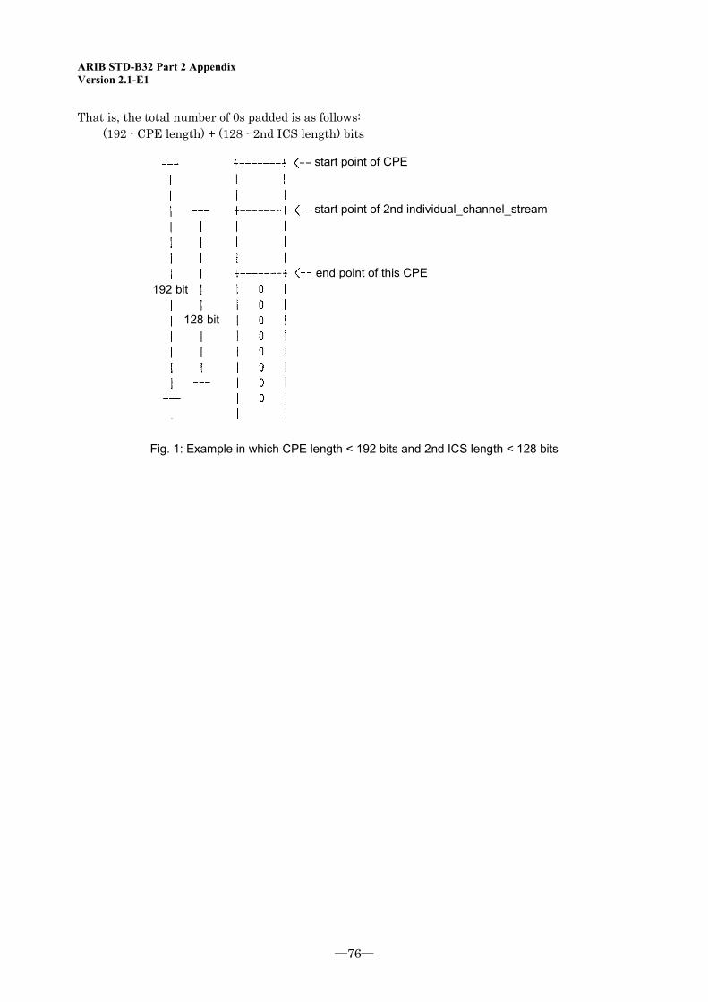
ARIB STD-B32 Part 2 Appendix Version 2.1-E1
―76―
That is, the total number of 0s padded is as follows: (192 - CPE length) + (128 - 2nd ICS length) bits
192 bit
128 bit
start point of CPE
start point of 2nd individual_channel_stream
end point of this CPE
Fig. 1: Example in which CPE length < 192 bits and 2nd ICS length < 128 bits
ARIB STD-B32 Part 2 Appendix Version 2.1-E1
-77-
Appendix 2: Overview of ISO/IEC 13818-1 AMD 6 (Related to AAC System Buffer)
The MPEG-2 Systems (ISO/IEC 13818-1) defines the system buffer size needed to decode audio and video data. This buffer size corresponds to the audio/video coding system. However, at the MPEG Dublin Conference held in July 1998, it was pointed out that the provision regarding AAC system buffer was unclear. The MPEG-2 Systems AMD 6 (Amendment 6 of the International Standard) was published in response.
(Note: At present, AMD 6 is an integral part of the MPEG-2 Systems Standard as ISO/IEC 13818-1: 2000. For the sake of convenience, it is called AMD 6 in this appendix.)
The MPEG-2 Systems AMD 6 defines four AAC system buffer sizes and leak rates for varying numbers of channels (up to 2, 8, 12 and 48 channels). The specific buffer sizes and leak rates are given below:
Leak rate (Rxn): Number of channels Rxn [bps] 1 – 2 2,000,000 3 – 8 5,529,600 9 – 12 8,294,400 13 – 48 33,177,600 Buffer size (BSn): Number of channels BSn [bytes] 1 – 2 3,584 3 – 8 8,976 9 – 12 12,804 9 – 48 51,216 Channels: Channels that require their own decoder buffer in this elementary stream n
With terrestrial and BS/broadband CS digital broadcasting systems in Japan, 5.1 channels are defined as the maximum number of AAC audio stream channels. According to the AMD 6 provision, the system layer must have the buffer size appropriate for the number of channels (3 to 8 channels). More specifically, the total buffer size shall be 9,488 bytes (BSn 8,976 bytes + transport buffer 512 bytes).
ARIB STD-B32 Part 2 Appendix Version 2.1-E1
―78―
Appendix 3: Precautions associated with revision to ISO/IEC 13818-7:2003
The first version of the MPEG-2 AAC standard (ISO/IEC 13818-7) was issued in 1997. Initially, the ISO/IEC 13818-7:1997 was supposed to be referenced when developing audio coding systems in digital terrestrial sound broadcasting, digital terrestrial television broadcasting, BS digital broadcasting, and broadband CS digital broadcasting.
Later in February 2004, AMD 1 of ISO/IEC 13818-7:2003 was partly referenced when specifying additional audio coding systems for digital satellite sound broadcasting in ARIB STD-B32 Ver. 1.5. In the revised version of ARIB STD-B32 Ver. 1.6 issued in May 2004, ISO/IEC 13818-7:2003 was referenced entirely. The following precautions should be taken as a result.
(1) Differences between ISO/IEC 13818-7:1997 and ISO/IEC 13818-7:2003 (excerption)
(a) Meaning of adts_buffer_fullness
No specification is given in ISO/IEC 13818-7:1997, but ISO/IEC 13818-7:2003 stipulates that adts_buffer_fullness is the "amount of remained equivalent buffer per channel (6,144 bits per channel)."
(b) Meaning of "minimum decoder input buffer"
No specification is given in ISO/IEC 13818-7:1997, but ISO/IEC 13818-7:2003 stipulates that there is no LFE component in the decoder buffer.
(2) Precautions
Some transmission devices manufactured and used on the basis of any ARIB STD-B32 version before Ver. 1.5 may not comply with the explanation given in ISO/IEC 13818-7:2003. Some of such devices are difficult to modify to make them compatible with ISO/IEC 13818-7:2003. The present standard is thus applied as follows in view of the revisions made to the referenced MPEG-2 AAC standard.
- The present standard does not apply to devices manufactured and used on the basis of any ARIB STD-B32 version before Ver. 1.5.
- Devices manufactured and used on the basis of ARIB STD-B32 Ver. 1.6 shall comply with the the explanation given in the referenced international standard ISO/IEC 13818-7:2003. A grace period of six months after the issuance of Ver. 1.6 (until November 2004) is granted.
When designing digital broadcasting receivers (defined by ARIB STD-B21) that comply with the present standard, due consideration must be given to the presence of streams based on different explanations associated with the revisions made to the MPEG-2 AAC standard.
ARIB STD-B32 Part 2 Appendix Version 2.1-E1
-79-
Appendix 4: Precautions associated with implementation of MPEG-2 AAC standard
This appendix explains the characteristics of coding tools used in the MPEG-2 AAC standard and presents precautions associated with the implementation of the standard.
(1) Treatment of AAC coding tools
The MPEG-2 AAC standard specifies three coding tools that can be used in the AAC LC profile: M/S Stereo, Intensity stereo, and TNS. Note that Prediction and Gain Control, which are beyond the usable range in the LC profile, cannot be used and that use of Coupling Channel is prohibited in Section 5.2.2 of Part 2 of the present standard.
The AAC standard stipulates that these coding tools shall be treated in the decoder according to bit streams. Namely, it is specified that decoding shall be carried out according to the bit stream no matter which coding tool is being used. This specification must be taken into account when designing and implementing decoders.
(2) TNS
When designing and implementing decoders, care must be taken on TNS, which may require a large number of steps for decoding. Although the highest TNS filter order in long window mode is restricted to 12 in the LC profile, compared with 20 in the Main profile, it is still possible that a large number of processing steps will be required. The factors that directly affect the number of steps for TNS decoding include the number of filters, filter order, filter length, and the number of channels.
In the case of a decoder DSP that performs fixed-point calculation, the required precision of operation may not be ensured when a high scaling level is adopted to avoid overflow or underflow caused by filtering (i.e., TNS may not be effective in improving sound quality). When designing and implementing decoder systems, therefore, care must be taken on overflow and underflow caused by filtering.
(3) Huffman decoding
The processing load of Huffman decoding tends to increase with bit rate. When designing and implementing decoders, theoretical maximum instantaneous rate must be taken into account in reference to the buffer model of the AAC standard. In the case of encoders, care must be taken to avoid excessively high maximum instantaneous rate when bit rate is relatively high.

ARIB STD-B32 Part 2 Appendix Version 2.1-E1
―80―
<Blank Page>
ARIB STD-B32 Part 3 Version 2.1-E1
―81―
Part 3: Signal Multiplexing System

ARIB STD-B32 Part 3 Version 2.1-E1
<Blank Page>
ARIB STD-B32 Part 3 Version 2.1-E1
-81-
Part 3: Signal Multiplexing System
Contents
Chapter 1: General Terms ..........................................................................................................................................83
1.1 Objective .......................................................................................................................................................83
1.2 Scope.............................................................................................................................................................83
1.3 References .....................................................................................................................................................83
1.3.1 Normative documents.............................................................................................................83
1.4 Terminology..................................................................................................................................................83
1.4.1 Definitions ...............................................................................................................................83
1.4.2 Abbreviations ..........................................................................................................................84
Chapter 2: Multiplexing System.................................................................................................................................85
2.1 Coded signals ................................................................................................................................................85
2.2 Transmission control signal (PSI) .................................................................................................................86
2.3 Emergency alarm signal ................................................................................................................................87
Chapter 3: Multiplexed Signal Format .......................................................................................................................88
3.1 PES packet ....................................................................................................................................................88
3.2 Section...........................................................................................................................................................89
3.3 TS packet.......................................................................................................................................................90
3.4 Transmission control signal (PSI) .................................................................................................................91
3.5 Descriptors ....................................................................................................................................................94
3.6 Identifiers ....................................................................................................................................................104
3.7 Structure and transmission procedure of conditional access related information........................................104

ARIB STD-B32 Part 3 Version 2.1-E1
-82-
<Blank Page>
ARIB STD-B32 Part 3 Version 2.1-E1
-83-
Chapter 1: General Terms
1.1 Objective The purpose of this standard is to define a signal multiplexing system for digital broadcasting (hereinafter referred to as terrestrial digital audio broadcasting) among the ultrashort-wave broadcasting handled by broadcasting stations (except assisted satellite broadcasting), digital broadcasting and high-definition television broadcasting (hereinafter referred to as digital terrestrial television broadcasting) among the various types of standard broadcasting methods to be handled by broadcasting stations, ultrashort-wave broadcasting (hereinafter referred to as satellite digital audio broadcasting) handled by broadcast satellite stations and broadcasting stations using frequency ranges greater than 2,630 MHz and less than or equal to 2,655 MHz, digital broadcasting (hereinafter referred to as BS digital broadcasting) among standard television, high-definition television , ultrashort-wave, and data broadcasting handled by broadcast satellite stations using frequency ranges greater than 11.7 GHz and less than or equal to 12.2 GHz, and standard television, high-definition television, ultrashort-wave, and data broadcasting (hereinafter referred to as broadband CS digital broadcasting) handled by broadcast satellite stations using frequency ranges greater than 12.2 GHz and less than or equal to 12.75 GHz and achieved through broadband transmission systems that comply with the “Standard transmission system for digital broadcasting among standard TV broadcasting and the like” (Ordinance No. 26 of the Ministry of Public Management, Home Affairs, Posts and Telecommunications, 2003).
1.2 Scope This standard applies to all terrestrial digital audio broadcasting, digital terrestrial television broadcasting, satellite digital audio broadcasting, BS digital broadcasting, and broadband CS digital brodadcasting, unless otherwise specified.
1.3 References 1.3.1 Normative documents
The standard incorporates excerpts from the following documents:
(1) “Standard transmission system for digital broadcasting among standard TV broadcasting and the like (Ordinance No. 26 of the Ministry of Public Management, Home Affairs, Posts and Telecommunications, 2003)” (hereinafter referred to as “Ordinance”)
(2) “Defining conditional access related information configuration and transmission procedure, transmission procedure for PES packets and the like, and transmission control signal and identifier configurations and the like (Notification No. 37 of the Ministry of Public Management, Home Affairs, Posts and Telecommunications, 2003)” (hereinafter referred to as “Notification”)
(3) ISO/IEC 13818-1:2000 | ITU-T Rec. H.222: Information technology – Generic coding of moving pictures and assoiated audio information: Systems (hereinafter referred to as “MPEG-2 Sytems”)
1.4 Terminology 1.4.1 Definitions
ARIB STD-B32 Part 3 Version 2.1-E1
-84-
Narrowband CS digital broadcasting: Standard television broadcasting, high-definition television broadcasting, ultrashort-wave broadcasting, and data broadcasting handled by broadcast satellite stations using frequency ranges greater than 12.2 GHz and less than or equal to 12.75 GHz and achieved through the narrowband transmission system as defined in Section 2 of Chapter 6 in Ordinance. Advanced narrowband CS digital broadcasting: Standard television broadcasting, high-definition television broadcasting, ultrashort-wave broadcasting, and data broadcasting handled by broadcast satellite stations using frequency ranges greater than 12.2 GHz and less than or equal to 12.75 GHz and achieved through the advanced narrowband transmission system as defined in Section 4 of Chapter 6 in Ordinance. 1.4.2 Abbreviations
PES: Packetized Elementary Stream CRC: Cyclic Redundancy Check TS: Transport Stream PMT: Program Map Table PAT: Program Association Table CAT: Conditional Access Table NIT: Network Information Table ECM: Entitlement Control Message EMM: Entitlement Management Message DSM-CC: Digital Storage Media Command and Control PID: Packet Identifier PCR: Program Clock Reference MHEG: Multimedia Hypermedia Expert Group BCD: Binary Coded Decimal
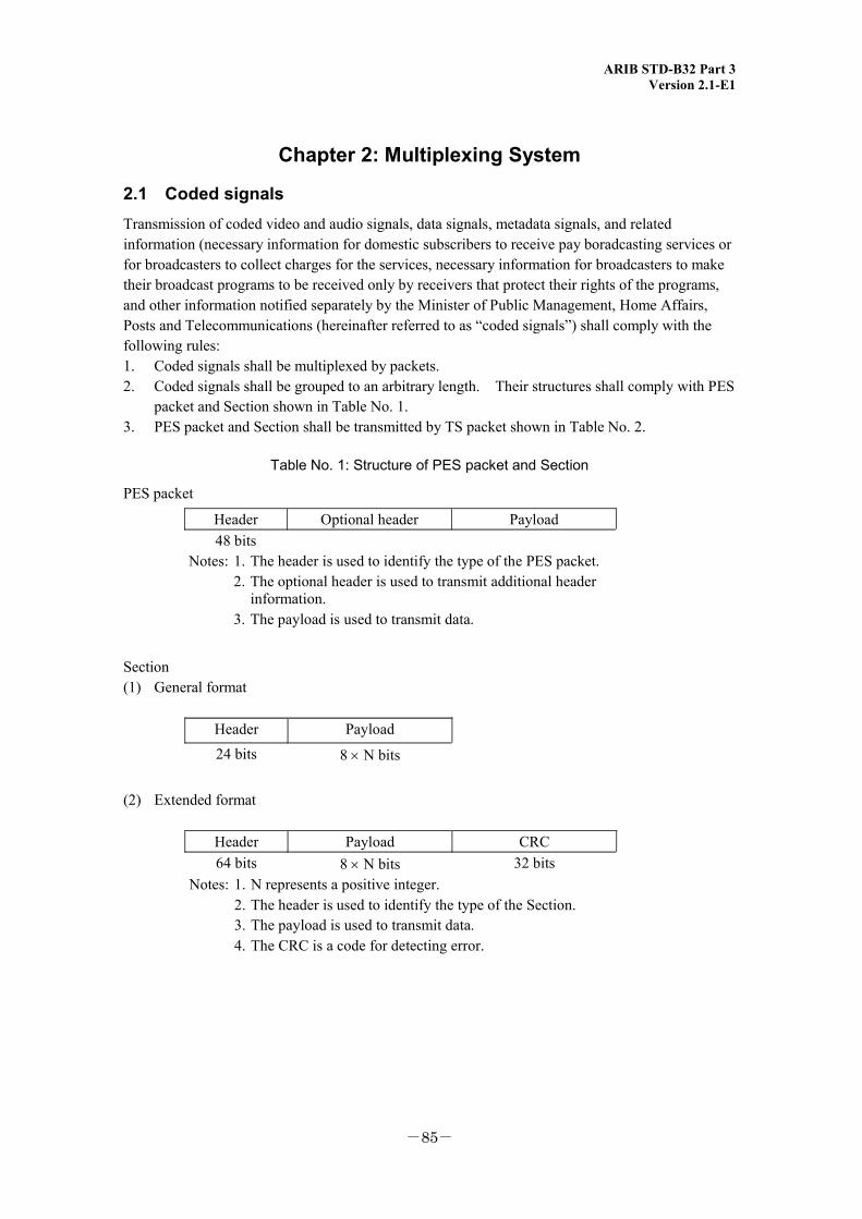
ARIB STD-B32 Part 3 Version 2.1-E1
-85-
Chapter 2: Multiplexing System
2.1 Coded signals Transmission of coded video and audio signals, data signals, metadata signals, and related information (necessary information for domestic subscribers to receive pay boradcasting services or for broadcasters to collect charges for the services, necessary information for broadcasters to make their broadcast programs to be received only by receivers that protect their rights of the programs, and other information notified separately by the Minister of Public Management, Home Affairs, Posts and Telecommunications (hereinafter referred to as “coded signals”) shall comply with the following rules: 1. Coded signals shall be multiplexed by packets. 2. Coded signals shall be grouped to an arbitrary length. Their structures shall comply with PES
packet and Section shown in Table No. 1. 3. PES packet and Section shall be transmitted by TS packet shown in Table No. 2.
Table No. 1: Structure of PES packet and Section
PES packet Header Optional header Payload
48 bits Notes: 1. The header is used to identify the type of the PES packet. 2. The optional header is used to transmit additional header
information. 3. The payload is used to transmit data.
Section (1) General format
Header Payload 24 bits 8 × N bits
(2) Extended format
Header Payload CRC 64 bits 8 × N bits 32 bits
Notes: 1. N represents a positive integer. 2. The header is used to identify the type of the Section. 3. The payload is used to transmit data. 4. The CRC is a code for detecting error.
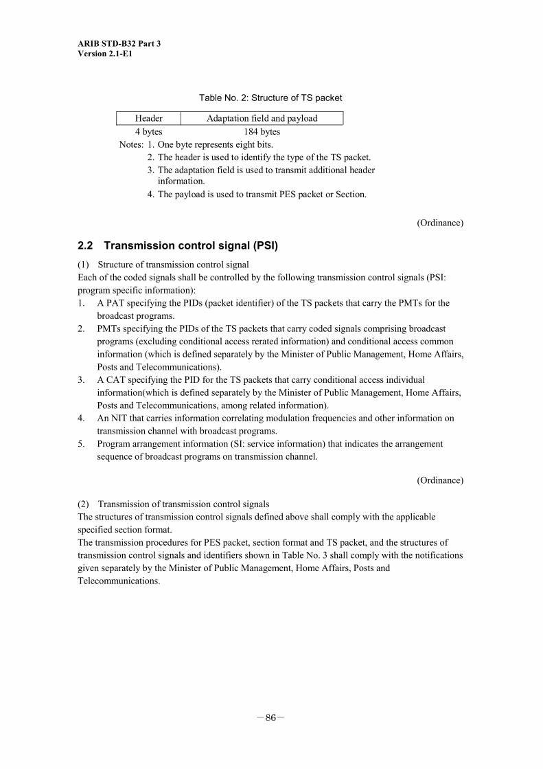
ARIB STD-B32 Part 3 Version 2.1-E1
-86-
Table No. 2: Structure of TS packet
Header Adaptation field and payload 4 bytes 184 bytes
Notes: 1. One byte represents eight bits. 2. The header is used to identify the type of the TS packet. 3. The adaptation field is used to transmit additional header
information. 4. The payload is used to transmit PES packet or Section.
(Ordinance)
2.2 Transmission control signal (PSI) (1) Structure of transmission control signal Each of the coded signals shall be controlled by the following transmission control signals (PSI: program specific information): 1. A PAT specifying the PIDs (packet identifier) of the TS packets that carry the PMTs for the
broadcast programs. 2. PMTs specifying the PIDs of the TS packets that carry coded signals comprising broadcast
programs (excluding conditional access rerated information) and conditional access common information (which is defined separately by the Minister of Public Management, Home Affairs, Posts and Telecommunications).
3. A CAT specifying the PID for the TS packets that carry conditional access individual information(which is defined separately by the Minister of Public Management, Home Affairs, Posts and Telecommunications, among related information).
4. An NIT that carries information correlating modulation frequencies and other information on transmission channel with broadcast programs.
5. Program arrangement information (SI: service information) that indicates the arrangement sequence of broadcast programs on transmission channel.
(Ordinance)
(2) Transmission of transmission control signals The structures of transmission control signals defined above shall comply with the applicable specified section format. The transmission procedures for PES packet, section format and TS packet, and the structures of transmission control signals and identifiers shown in Table No. 3 shall comply with the notifications given separately by the Minister of Public Management, Home Affairs, Posts and Telecommunications.
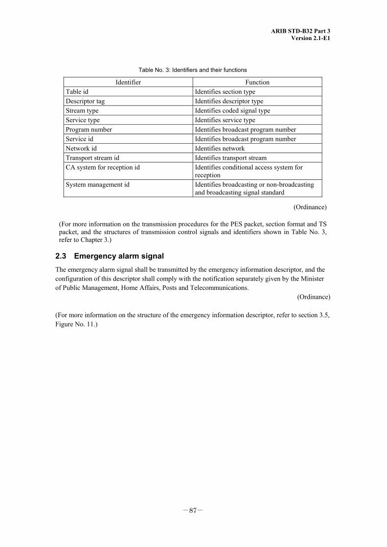
ARIB STD-B32 Part 3 Version 2.1-E1
-87-
Table No. 3: Identifiers and their functions
Identifier Function Table id Identifies section type Descriptor tag Identifies descriptor type Stream type Identifies coded signal type Service type Identifies service type Program number Identifies broadcast program number Service id Identifies broadcast program number Network id Identifies network Transport stream id Identifies transport stream CA system for reception id Identifies conditional access system for
reception System management id Identifies broadcasting or non-broadcasting
and broadcasting signal standard
(Ordinance)
(For more information on the transmission procedures for the PES packet, section format and TS packet, and the structures of transmission control signals and identifiers shown in Table No. 3, refer to Chapter 3.)
2.3 Emergency alarm signal The emergency alarm signal shall be transmitted by the emergency information descriptor, and the configuration of this descriptor shall comply with the notification separately given by the Minister of Public Management, Home Affairs, Posts and Telecommunications.
(Ordinance)
(For more information on the structure of the emergency information descriptor, refer to section 3.5, Figure No. 11.)
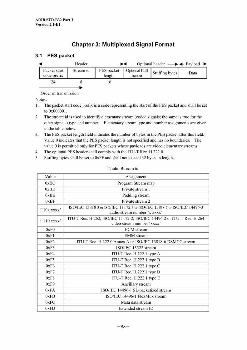
ARIB STD-B32 Part 3 Version 2.1-E1
-88-
Chapter 3: Multiplexed Signal Format
3.1 PES packet Header Optional header Payload
Packet start code prefix
Stream id PES packet length
Optional PES header Stuffing bytes Data
24
8
16
Order of transmission Notes: 1. The packet start code prefix is a code representing the start of the PES packet and shall be set
to 0x000001. 2. The stream id is used to identify elementary stream (coded signals; the same is true for the
other signals) type and number. Elementary stream type and number assignments are given in the table below.
3. The PES packet length field indicates the number of bytes in the PES packet after this field. Value 0 indicates that the PES packet length is not specified and has no boundaries. The value 0 is permitted only for PES packets whose payloads are video elementary streams.
4. The optional PES header shall comply with the ITU-T Rec. H.222.0. 5. Stuffing bytes shall be set to 0xFF and shall not exceed 32 bytes in length.
Table: Stream id
Value Assignment 0xBC Program Stream map 0xBD Private stream 1 0xBE Padding stream 0xBF Private stream 2
‘110x xxxx’ ISO/IEC 13818-3 or ISO/IEC 11172-3 or ISO/IEC 13818-7 or ISO/IEC 14496-3 audio stream number ‘x xxxx’
‘1110 xxxx’ ITU-T Rec. H.262, ISO/IEC 11172-2, ISO/IEC 14496-2 or ITU-T Rec. H.264 video stream number ‘xxxx’
0xF0 ECM stream 0xF1 EMM stream 0xF2 ITU-T Rec. H.222.0 Annex A or ISO/IEC 13818-6 DSMCC stream 0xF3 ISO/IEC 13522 stream 0xF4 ITU-T Rec. H.222.1 type A 0xF5 ITU-T Rec. H.222.1 type B 0xF6 ITU-T Rec. H.222.1 type C 0xF7 ITU-T Rec. H.222.1 type D 0xF8 ITU-T Rec. H.222.1 type E 0xF9 Ancillary stream 0xFA ISO/IEC 14496-1 SL-packetized stream 0xFB ISO/IEC 14496-1 FlexMux stream 0xFC Meta data stream 0xFD Extended stream ID
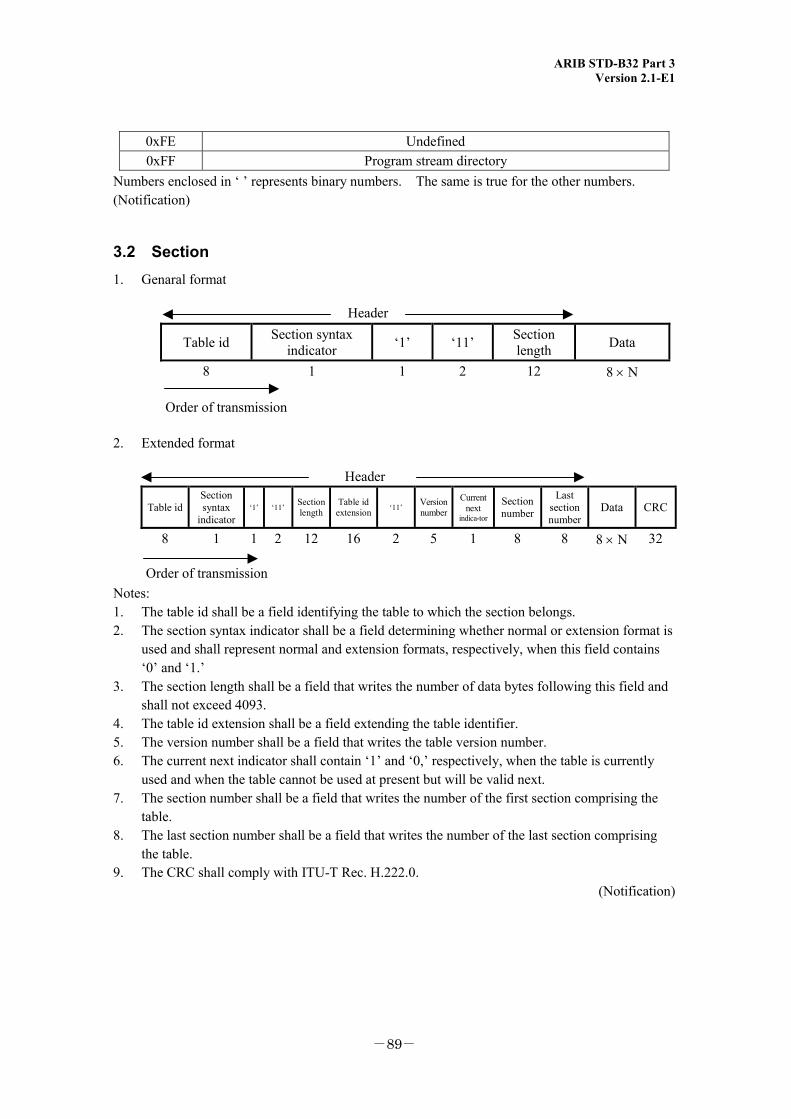
ARIB STD-B32 Part 3 Version 2.1-E1
-89-
0xFE Undefined 0xFF Program stream directory
Numbers enclosed in ‘ ’ represents binary numbers. The same is true for the other numbers. (Notification)
3.2 Section 1. Genaral format
Header
Table id Section syntax indicator ‘1’ ‘11’ Section
length Data
8
1 1 2 12 8 × N
Order of transmission
2. Extended format
Header
Table id Section syntax
indicator‘1’ ‘11’ Section
length Table id
extension ‘11’ Version number
Current next
indica-tor
Section number
Last section number
Data CRC
8 1 1 2 12 16 2 5 1 8 8 8 × N 32
Order of transmission
Notes: 1. The table id shall be a field identifying the table to which the section belongs. 2. The section syntax indicator shall be a field determining whether normal or extension format is
used and shall represent normal and extension formats, respectively, when this field contains ‘0’ and ‘1.’
3. The section length shall be a field that writes the number of data bytes following this field and shall not exceed 4093.
4. The table id extension shall be a field extending the table identifier. 5. The version number shall be a field that writes the table version number. 6. The current next indicator shall contain ‘1’ and ‘0,’ respectively, when the table is currently
used and when the table cannot be used at present but will be valid next. 7. The section number shall be a field that writes the number of the first section comprising the
table. 8. The last section number shall be a field that writes the number of the last section comprising
the table. 9. The CRC shall comply with ITU-T Rec. H.222.0.
(Notification)
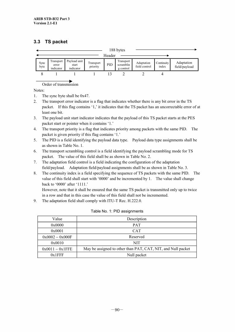
ARIB STD-B32 Part 3 Version 2.1-E1
-90-
3.3 TS packet
188 bytes Header
Sync byte
Transport error
indicator
Payload unit start
indicator
Transport priority PID
Transport scrambling control
Adaptation field control
Continuity index
Adaptation field/payload
8 1 1 1 13 2 2 4
Order of transmission
Notes: 1. The sync byte shall be 0x47. 2. The transport error indicator is a flag that indicates whether there is any bit error in the TS
packet. If this flag contains ‘1,’ it indicates that the TS packet has an uncorrectable error of at least one bit.
3. The payload unit start indicator indicates that the payload of this TS packet starts at the PES packet start or pointer when it contains ‘1.’
4. The transport priority is a flag that indicates priority among packets with the same PID. The packet is given priority if this flag contains ‘1.’
5. The PID is a field identifying the payload data type. Payload data type assignments shall be as shown in Table No. 1.
6. The transport scrambling control is a field identifying the payload scrambling mode for TS packet. The value of this field shall be as shown in Table No. 2.
7. The adaptation field control is a field indicating the configuration of the adaptation field/payload. Adaptation field/payload assignments shall be as shown in Table No. 3.
8. The continuity index is a field specifying the sequence of TS packets with the same PID. The value of this field shall start with ‘0000’ and be incremented by 1. The value shall change back to ‘0000’ after ‘1111.’
However, note that it shall be ensured that the same TS packet is transmitted only up to twice in a row and that in this case the value of this field shall not be incremented.
9. The adaptation field shall comply with ITU-T Rec. H.222.0.
Table No. 1: PID assignments
Value Description 0x0000 PAT 0x0001 CAT
0x0002 − 0x000F Reserved 0x0010 NIT
0x0011 − 0x1FFE May be assigned to other than PAT, CAT, NIT, and Null packet 0x1FFF Null packet
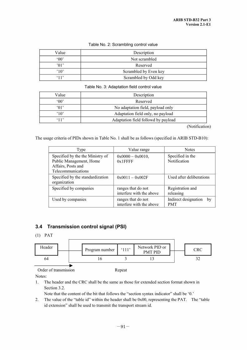
ARIB STD-B32 Part 3 Version 2.1-E1
-91-
Table No. 2: Scrambling control value
Value Description ‘00’ Not scrambled ’01’ Reserved ’10’ Scrambled by Even key ‘11’ Scrambled by Odd key
Table No. 3: Adaptation field control value
Value Description ‘00’ Reserved ’01’ No adaptation field, payload only ’10’ Adaptation field only, no payload ‘11’ Adaptation field followd by payload
(Notification)
The usage criteria of PIDs shown in Table No. 1 shall be as follows (specified in ARIB STD-B10):
Type Value range Notes Specified by the the Ministry of Public Management, Home Affairs, Posts and Telecommunications
0x0000 − 0x0010, 0x1FFFF
Specified in the Notification
Specified by the standardization organization
0x0011 − 0x002F Used after deliberations
Specified by companies ranges that do not interfere with the above
Registration and releasing
Used by companies ranges that do not interfere with the above
Indirect designation by PMT
3.4 Transmission control signal (PSI) (1) PAT
Header Program number ‘111’ Network PID or
PMT PID CRC
64
16 3 13 32
Order of transmission Repeat Notes: 1. The header and the CRC shall be the same as those for extended section format shown in
Section 3.2. Note that the content of the bit that follows the “section syntax indicator” shall be ‘0.’ 2. The value of the “table id” within the header shall be 0x00, representing the PAT. The “table
id extension” shall be used to transmit the transport stream id.
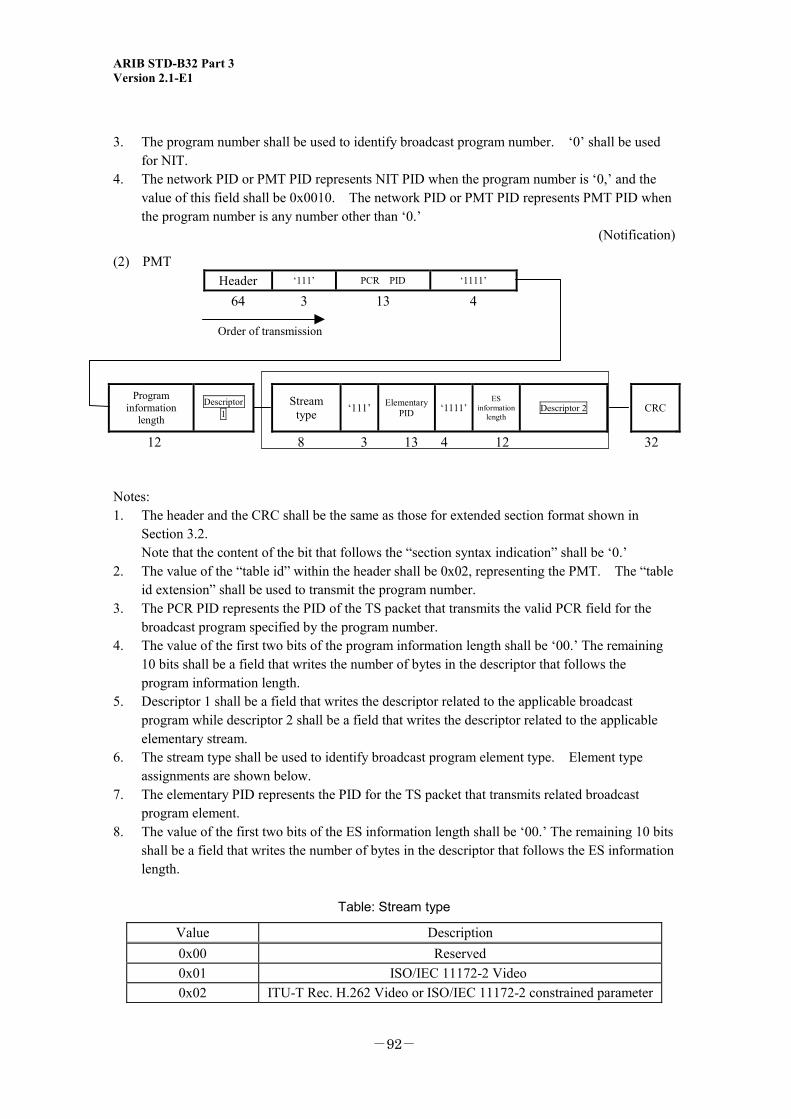
ARIB STD-B32 Part 3 Version 2.1-E1
-92-
3. The program number shall be used to identify broadcast program number. ‘0’ shall be used for NIT.
4. The network PID or PMT PID represents NIT PID when the program number is ‘0,’ and the value of this field shall be 0x0010. The network PID or PMT PID represents PMT PID when the program number is any number other than ‘0.’
(Notification)
(2) PMT Header ‘111’ PCR PID ‘1111’
64 3 13 4
Order of transmission
Program information
length
Descriptor 1
Stream type ‘111’ Elementary
PID ‘1111’ES
information length
Descriptor 2
CRC
12 8 3 13 4 12 32
Notes: 1. The header and the CRC shall be the same as those for extended section format shown in
Section 3.2. Note that the content of the bit that follows the “section syntax indication” shall be ‘0.’ 2. The value of the “table id” within the header shall be 0x02, representing the PMT. The “table
id extension” shall be used to transmit the program number. 3. The PCR PID represents the PID of the TS packet that transmits the valid PCR field for the
broadcast program specified by the program number. 4. The value of the first two bits of the program information length shall be ‘00.’ The remaining
10 bits shall be a field that writes the number of bytes in the descriptor that follows the program information length.
5. Descriptor 1 shall be a field that writes the descriptor related to the applicable broadcast program while descriptor 2 shall be a field that writes the descriptor related to the applicable elementary stream.
6. The stream type shall be used to identify broadcast program element type. Element type assignments are shown below.
7. The elementary PID represents the PID for the TS packet that transmits related broadcast program element.
8. The value of the first two bits of the ES information length shall be ‘00.’ The remaining 10 bits shall be a field that writes the number of bytes in the descriptor that follows the ES information length.
Table: Stream type
Value Description 0x00 Reserved 0x01 ISO/IEC 11172-2 Video 0x02 ITU-T Rec. H.262 Video or ISO/IEC 11172-2 constrained parameter
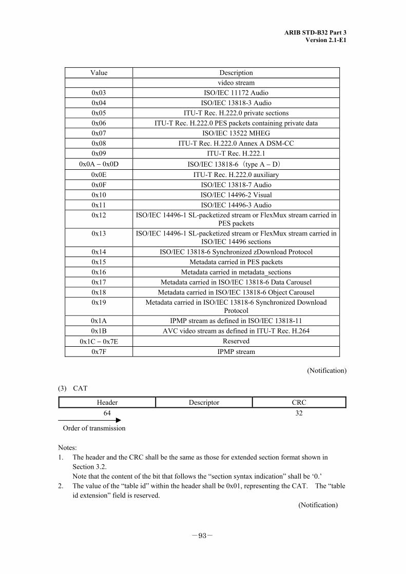
ARIB STD-B32 Part 3 Version 2.1-E1
-93-
Value Description video stream
0x03 ISO/IEC 11172 Audio 0x04 ISO/IEC 13818-3 Audio 0x05 ITU-T Rec. H.222.0 private sections 0x06 ITU-T Rec. H.222.0 PES packets containing private data 0x07 ISO/IEC 13522 MHEG 0x08 ITU-T Rec. H.222.0 Annex A DSM-CC 0x09 ITU-T Rec. H.222.1
0x0A − 0x0D ISO/IEC 13818-6(type A − D) 0x0E ITU-T Rec. H.222.0 auxiliary 0x0F ISO/IEC 13818-7 Audio 0x10 ISO/IEC 14496-2 Visual 0x11 ISO/IEC 14496-3 Audio 0x12 ISO/IEC 14496-1 SL-packetized stream or FlexMux stream carried in
PES packets 0x13 ISO/IEC 14496-1 SL-packetized stream or FlexMux stream carried in
ISO/IEC 14496 sections 0x14 ISO/IEC 13818-6 Synchronized zDownload Protocol 0x15 Metadata carried in PES packets 0x16 Metadata carried in metadata_sections 0x17 Metadata carried in ISO/IEC 13818-6 Data Carousel 0x18 Metadata carried in ISO/IEC 13818-6 Object Carousel 0x19 Metadata carried in ISO/IEC 13818-6 Synchronized Download
Protocol 0x1A IPMP stream as defined in ISO/IEC 13818-11 0x1B AVC video stream as defined in ITU-T Rec. H.264
0x1C − 0x7E Reserved 0x7F IPMP stream
(Notification)
(3) CAT
Header Descriptor CRC 64 32
Order of transmission
Notes: 1. The header and the CRC shall be the same as those for extended section format shown in
Section 3.2. Note that the content of the bit that follows the “section syntax indication” shall be ‘0.’ 2. The value of the “table id” within the header shall be 0x01, representing the CAT. The “table
id extension” field is reserved. (Notification)
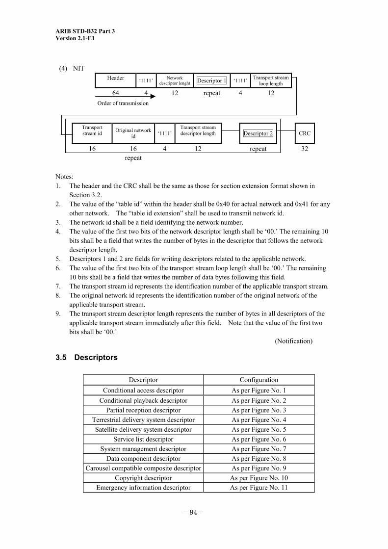
ARIB STD-B32 Part 3 Version 2.1-E1
-94-
(4) NIT Header ‘1111’ Network
descriptor lenght Descriptor 1 ‘1111’ Transport stream loop length
64 4 12 repeat 4 12 Order of transmission
Transport stream id Original network
id ‘1111’Transport stream descriptor length Descriptor 2
CRC
16 16 4 12 repeat 32 repeat
Notes: 1. The header and the CRC shall be the same as those for section extension format shown in
Section 3.2. 2. The value of the “table id” within the header shall be 0x40 for actual network and 0x41 for any
other network. The “table id extension” shall be used to transmit network id. 3. The network id shall be a field identifying the network number. 4. The value of the first two bits of the network descriptor length shall be ‘00.’ The remaining 10
bits shall be a field that writes the number of bytes in the descriptor that follows the network descriptor length.
5. Descriptors 1 and 2 are fields for writing descriptors related to the applicable network. 6. The value of the first two bits of the transport stream loop length shall be ‘00.’ The remaining
10 bits shall be a field that writes the number of data bytes following this field. 7. The transport stream id represents the identification number of the applicable transport stream. 8. The original network id represents the identification number of the original network of the
applicable transport stream. 9. The transport stream descriptor length represents the number of bytes in all descriptors of the
applicable transport stream immediately after this field. Note that the value of the first two bits shall be ‘00.’ (Notification)
3.5 Descriptors
Descriptor Configuration Conditional access descriptor As per Figure No. 1
Conditional playback descriptor As per Figure No. 2 Partial reception descriptor As per Figure No. 3
Terrestrial delivery system descriptor As per Figure No. 4 Satellite delivery system descriptor As per Figure No. 5
Service list descriptor As per Figure No. 6 System management descriptor As per Figure No. 7
Data component descriptor As per Figure No. 8 Carousel compatible composite descriptor As per Figure No. 9
Copyright descriptor As per Figure No. 10 Emergency information descriptor As per Figure No. 11
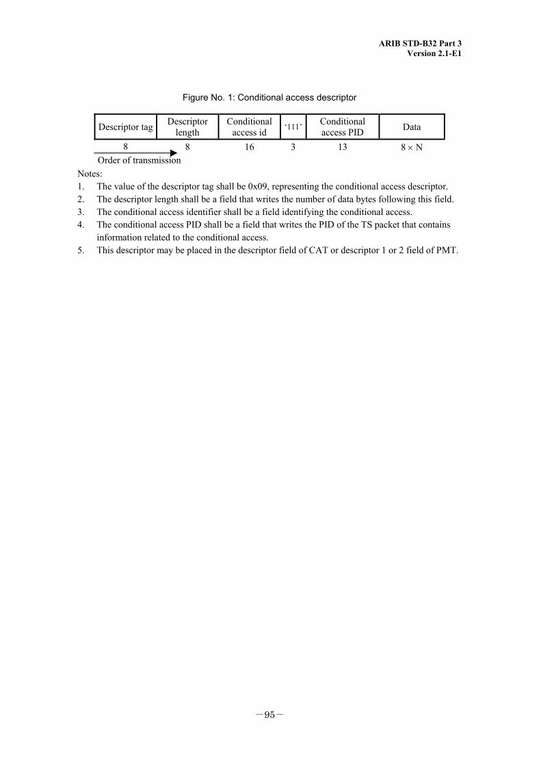
ARIB STD-B32 Part 3 Version 2.1-E1
-95-
Figure No. 1: Conditional access descriptor
Descriptor tag Descriptor length
Conditional access id ‘111’ Conditional
access PID Data
8 8 16 3 13 8 × N Order of transmission
Notes: 1. The value of the descriptor tag shall be 0x09, representing the conditional access descriptor. 2. The descriptor length shall be a field that writes the number of data bytes following this field. 3. The conditional access identifier shall be a field identifying the conditional access. 4. The conditional access PID shall be a field that writes the PID of the TS packet that contains
information related to the conditional access. 5. This descriptor may be placed in the descriptor field of CAT or descriptor 1 or 2 field of PMT.
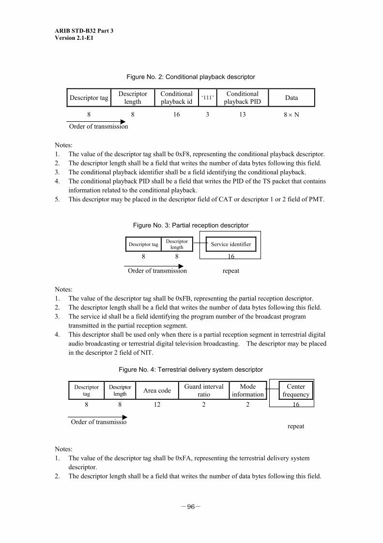
ARIB STD-B32 Part 3 Version 2.1-E1
-96-
Figure No. 2: Conditional playback descriptor
Descriptor tag Descriptor length
Conditional playback id ‘111’ Conditional
playback PID Data
8 8 16 3 13 8 × N
Order of transmission Notes: 1. The value of the descriptor tag shall be 0xF8, representing the conditional playback descriptor. 2. The descriptor length shall be a field that writes the number of data bytes following this field. 3. The conditional playback identifier shall be a field identifying the conditional playback. 4. The conditional playback PID shall be a field that writes the PID of the TS packet that contains
information related to the conditional playback. 5. This descriptor may be placed in the descriptor field of CAT or descriptor 1 or 2 field of PMT.
Figure No. 3: Partial reception descriptor
Descriptor tag Descriptor length
Service identifier
8 8 16
Order of transmission repeat Notes: 1. The value of the descriptor tag shall be 0xFB, representing the partial reception descriptor. 2. The descriptor length shall be a field that writes the number of data bytes following this field. 3. The service id shall be a field identifying the program number of the broadcast program
transmitted in the partial reception segment. 4. This descriptor shall be used only when there is a partial reception segment in terrestrial digital
audio broadcasting or terrestrial digital television broadcasting. The descriptor may be placed in the descriptor 2 field of NIT.
Figure No. 4: Terrestrial delivery system descriptor
Descriptor tag
Descriptor length Area code Guard interval
ratio Mode
information Center
frequency 8 8 12
2 2 16
Order of transmissio
repeat
Notes: 1. The value of the descriptor tag shall be 0xFA, representing the terrestrial delivery system
descriptor. 2. The descriptor length shall be a field that writes the number of data bytes following this field.
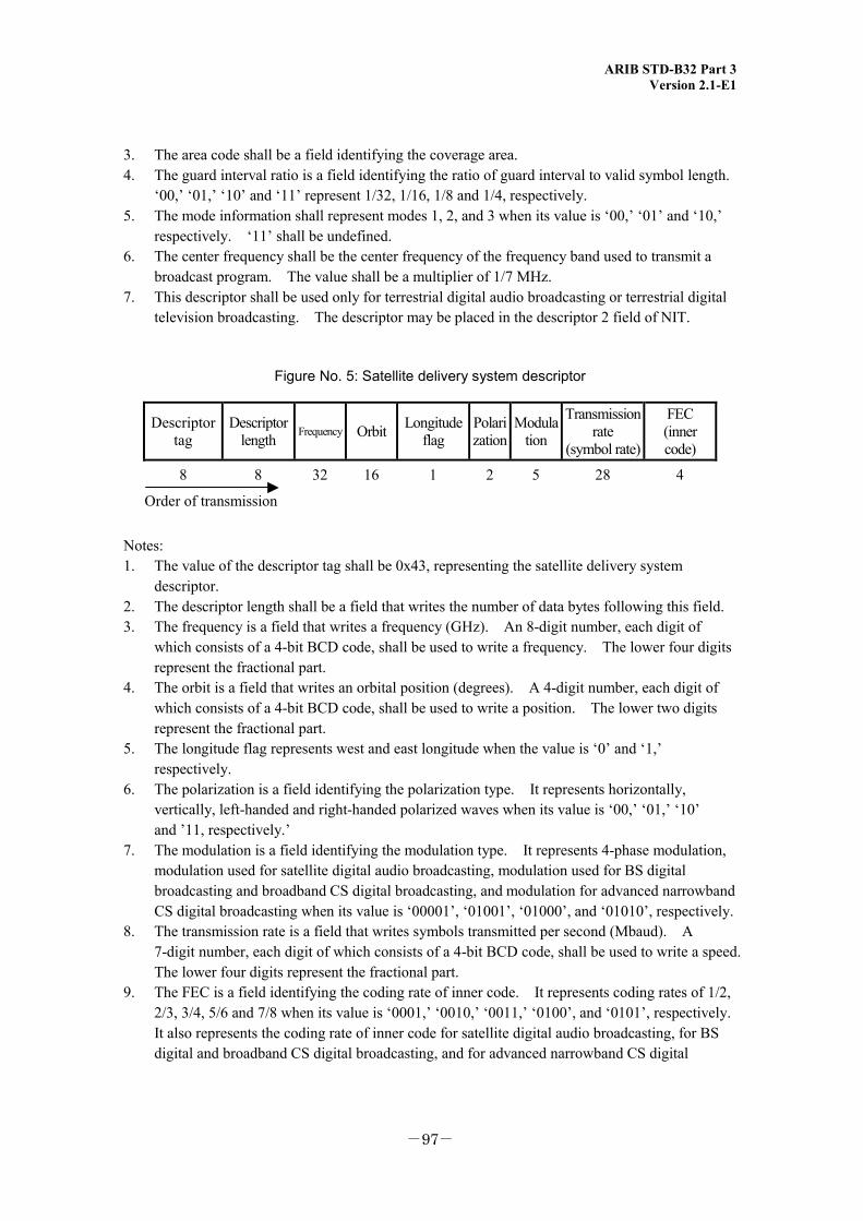
ARIB STD-B32 Part 3 Version 2.1-E1
-97-
3. The area code shall be a field identifying the coverage area. 4. The guard interval ratio is a field identifying the ratio of guard interval to valid symbol length.
‘00,’ ‘01,’ ‘10’ and ‘11’ represent 1/32, 1/16, 1/8 and 1/4, respectively. 5. The mode information shall represent modes 1, 2, and 3 when its value is ‘00,’ ‘01’ and ‘10,’
respectively. ‘11’ shall be undefined. 6. The center frequency shall be the center frequency of the frequency band used to transmit a
broadcast program. The value shall be a multiplier of 1/7 MHz. 7. This descriptor shall be used only for terrestrial digital audio broadcasting or terrestrial digital
television broadcasting. The descriptor may be placed in the descriptor 2 field of NIT.
Figure No. 5: Satellite delivery system descriptor
Descriptor tag
Descriptor length Frequency Orbit Longitude
flag Polarization
Modulation
Transmission rate
(symbol rate)
FEC (inner code)
8 8 32 16 1 2 5 28 4
Order of transmission Notes: 1. The value of the descriptor tag shall be 0x43, representing the satellite delivery system
descriptor. 2. The descriptor length shall be a field that writes the number of data bytes following this field. 3. The frequency is a field that writes a frequency (GHz). An 8-digit number, each digit of
which consists of a 4-bit BCD code, shall be used to write a frequency. The lower four digits represent the fractional part.
4. The orbit is a field that writes an orbital position (degrees). A 4-digit number, each digit of which consists of a 4-bit BCD code, shall be used to write a position. The lower two digits represent the fractional part.
5. The longitude flag represents west and east longitude when the value is ‘0’ and ‘1,’ respectively.
6. The polarization is a field identifying the polarization type. It represents horizontally, vertically, left-handed and right-handed polarized waves when its value is ‘00,’ ‘01,’ ‘10’ and ’11, respectively.’
7. The modulation is a field identifying the modulation type. It represents 4-phase modulation, modulation used for satellite digital audio broadcasting, modulation used for BS digital broadcasting and broadband CS digital broadcasting, and modulation for advanced narrowband CS digital broadcasting when its value is ‘00001’, ‘01001’, ‘01000’, and ‘01010’, respectively.
8. The transmission rate is a field that writes symbols transmitted per second (Mbaud). A 7-digit number, each digit of which consists of a 4-bit BCD code, shall be used to write a speed. The lower four digits represent the fractional part.
9. The FEC is a field identifying the coding rate of inner code. It represents coding rates of 1/2, 2/3, 3/4, 5/6 and 7/8 when its value is ‘0001,’ ‘0010,’ ‘0011,’ ‘0100’, and ‘0101’, respectively. It also represents the coding rate of inner code for satellite digital audio broadcasting, for BS digital and broadband CS digital broadcasting, and for advanced narrowband CS digital
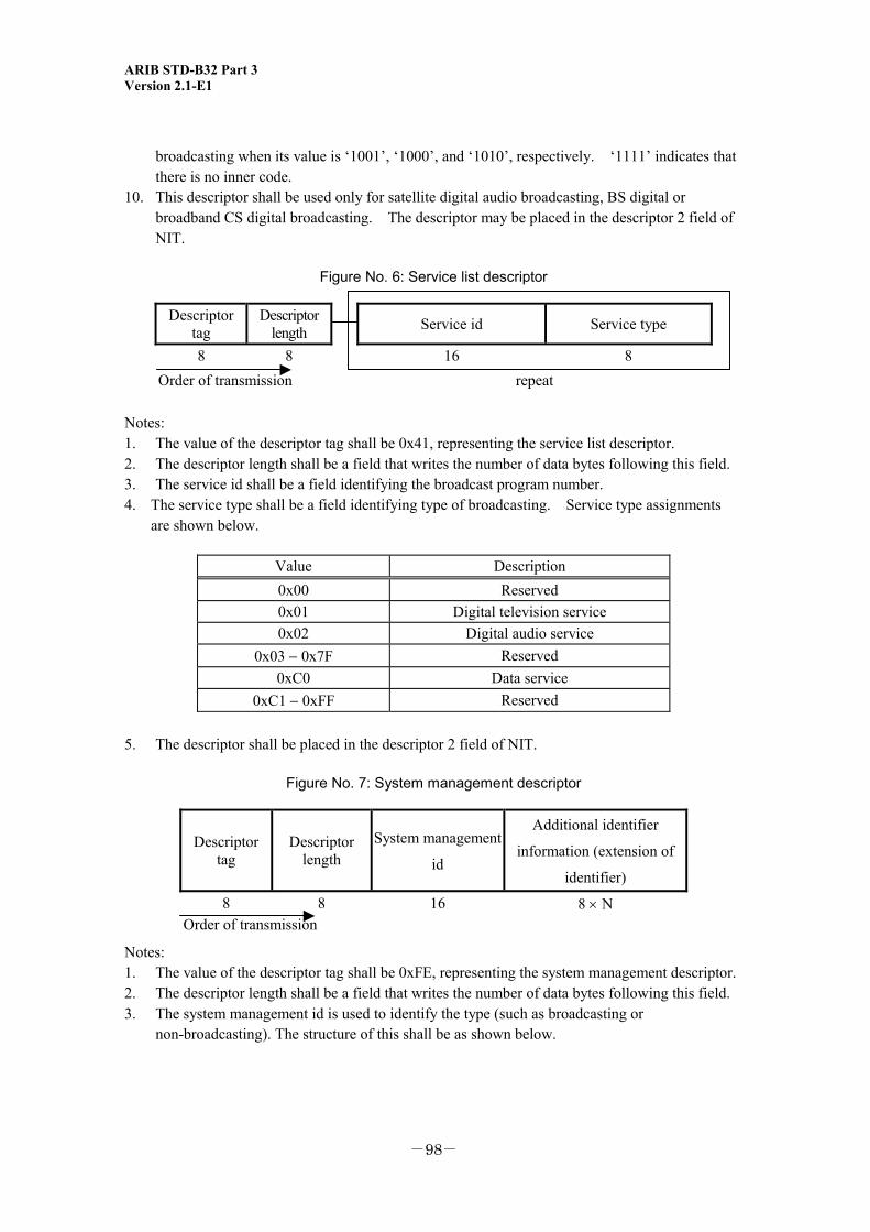
ARIB STD-B32 Part 3 Version 2.1-E1
-98-
broadcasting when its value is ‘1001’, ‘1000’, and ‘1010’, respectively. ‘1111’ indicates that there is no inner code.
10. This descriptor shall be used only for satellite digital audio broadcasting, BS digital or broadband CS digital broadcasting. The descriptor may be placed in the descriptor 2 field of NIT.
Figure No. 6: Service list descriptor
Descriptor tag
Descriptor length
Service id Service type
8 8 16 8 Order of transmission repeat
Notes: 1. The value of the descriptor tag shall be 0x41, representing the service list descriptor. 2. The descriptor length shall be a field that writes the number of data bytes following this field. 3. The service id shall be a field identifying the broadcast program number. 4. The service type shall be a field identifying type of broadcasting. Service type assignments
are shown below.
Value Description 0x00 Reserved 0x01 Digital television service 0x02 Digital audio service
0x03 − 0x7F Reserved 0xC0 Data service
0xC1 − 0xFF Reserved 5. The descriptor shall be placed in the descriptor 2 field of NIT.
Figure No. 7: System management descriptor
Descriptor tag
Descriptor length
System management
id
Additional identifier
information (extension of
identifier)
8 8 16 8 × N Order of transmission
Notes: 1. The value of the descriptor tag shall be 0xFE, representing the system management descriptor. 2. The descriptor length shall be a field that writes the number of data bytes following this field. 3. The system management id is used to identify the type (such as broadcasting or
non-broadcasting). The structure of this shall be as shown below.
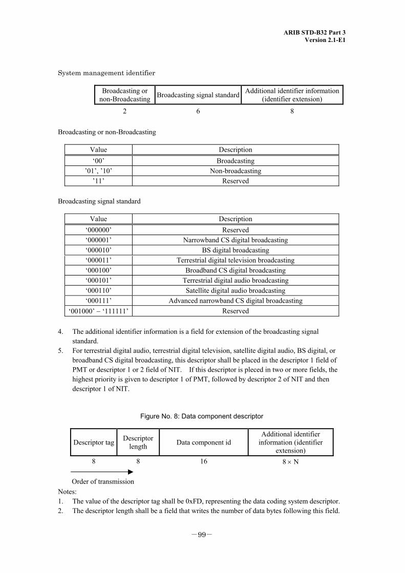
ARIB STD-B32 Part 3 Version 2.1-E1
-99-
System management identifier
Broadcasting or non-Broadcasting Broadcasting signal standard Additional identifier information
(identifier extension)
2 6 8 Broadcasting or non-Broadcasting
Value Description ‘00’ Broadcasting
’01’, ’10’ Non-broadcasting ’11’ Reserved
Broadcasting signal standard
Value Description ‘000000’ Reserved ‘000001’ Narrowband CS digital broadcasting ‘000010’ BS digital broadcasting ‘000011’ Terrestrial digital television broadcasting ‘000100’ Broadband CS digital broadcasting ‘000101’ Terrestrial digital audio broadcasting ‘000110’ Satellite digital audio broadcasting ‘000111’ Advanced narrowband CS digital broadcasting
‘001000’ − ‘111111’ Reserved
4. The additional identifier information is a field for extension of the broadcasting signal standard.
5. For terrestrial digital audio, terrestrial digital television, satellite digital audio, BS digital, or broadband CS digital broadcasting, this descriptor shall be placed in the descriptor 1 field of PMT or descriptor 1 or 2 field of NIT. If this descriptor is pleced in two or more fields, the highest priority is given to descriptor 1 of PMT, followed by descriptor 2 of NIT and then descriptor 1 of NIT.
Figure No. 8: Data component descriptor
Descriptor tag Descriptor length Data component id
Additional identifier information (identifier
extension) 8 8 16 8 × N
Order of transmission Notes: 1. The value of the descriptor tag shall be 0xFD, representing the data coding system descriptor. 2. The descriptor length shall be a field that writes the number of data bytes following this field.

ARIB STD-B32 Part 3 Version 2.1-E1
-100-
3. The data component id is a field identifying the data coding system standard. 4. The additional identifier information is a field for extension of the data coding system
standard. 5. This descriptor may be placed in the descriptor 2 field of PMT.
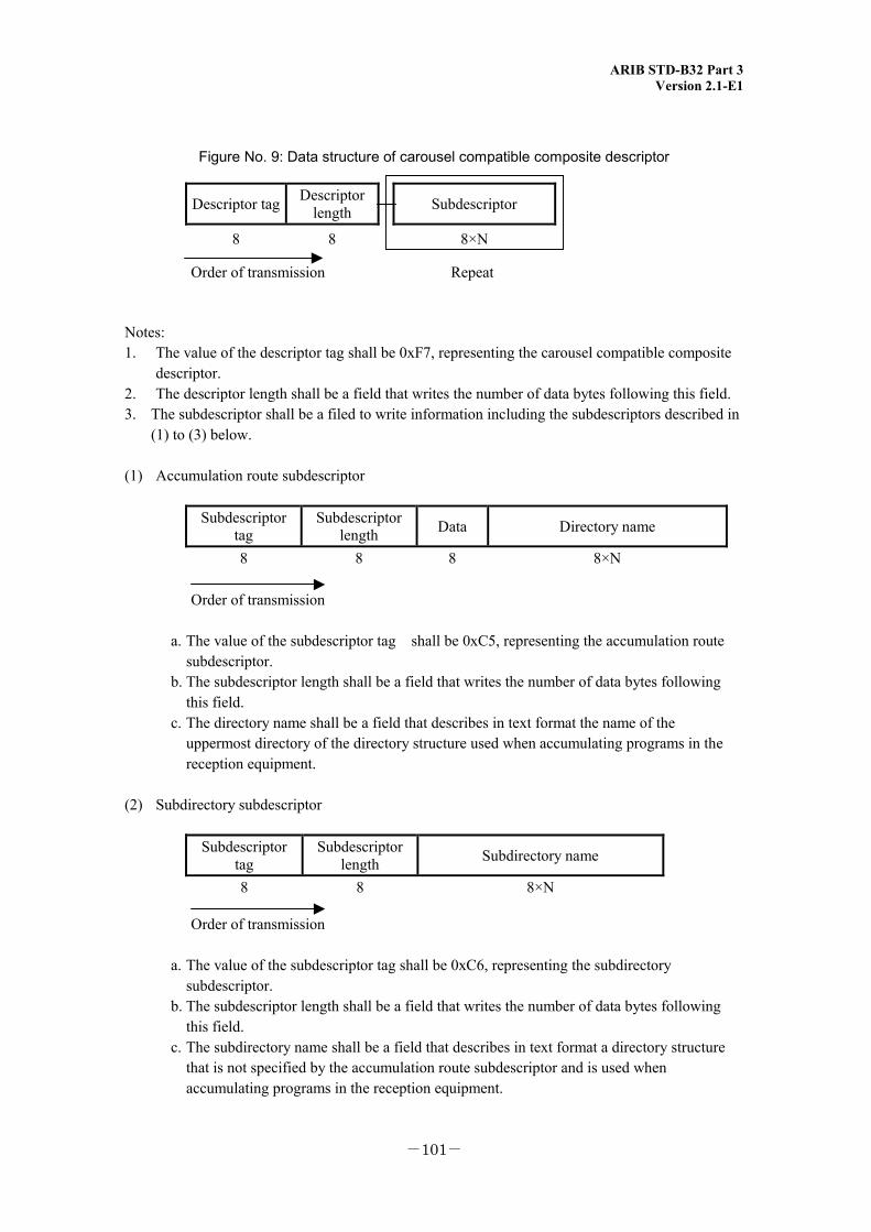
ARIB STD-B32 Part 3 Version 2.1-E1
-101-
Figure No. 9: Data structure of carousel compatible composite descriptor
Notes: 1. The value of the descriptor tag shall be 0xF7, representing the carousel compatible composite
descriptor. 2. The descriptor length shall be a field that writes the number of data bytes following this field. 3. The subdescriptor shall be a filed to write information including the subdescriptors described in
(1) to (3) below. (1) Accumulation route subdescriptor
Subdescriptor tag
Subdescriptor length Data Directory name
8 8 8 8×N
Order of transmission
a. The value of the subdescriptor tag shall be 0xC5, representing the accumulation route subdescriptor.
b. The subdescriptor length shall be a field that writes the number of data bytes following this field.
c. The directory name shall be a field that describes in text format the name of the uppermost directory of the directory structure used when accumulating programs in the reception equipment.
(2) Subdirectory subdescriptor
Subdescriptor tag
Subdescriptor length Subdirectory name
8 8 8×N
Order of transmission
a. The value of the subdescriptor tag shall be 0xC6, representing the subdirectory subdescriptor.
b. The subdescriptor length shall be a field that writes the number of data bytes following this field.
c. The subdirectory name shall be a field that describes in text format a directory structure that is not specified by the accumulation route subdescriptor and is used when accumulating programs in the reception equipment.
Descriptor tag Descriptor length Subdescriptor
8 8 8×N
Order of transmission Repeat
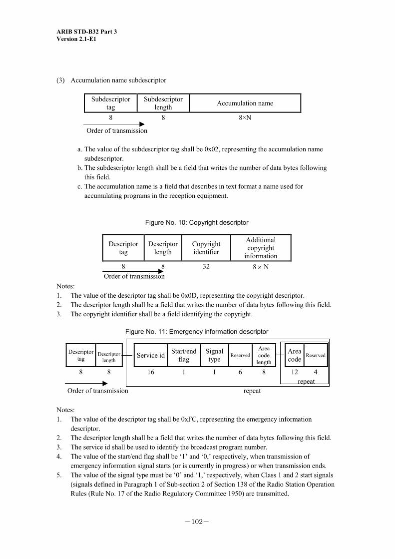
ARIB STD-B32 Part 3 Version 2.1-E1
-102-
(3) Accumulation name subdescriptor
Subdescriptor tag
Subdescriptor length Accumulation name
8 8 8×N
Order of transmission
a. The value of the subdescriptor tag shall be 0x02, representing the accumulation name subdescriptor.
b. The subdescriptor length shall be a field that writes the number of data bytes following this field.
c. The accumulation name is a field that describes in text format a name used for accumulating programs in the reception equipment.
Figure No. 10: Copyright descriptor
Descriptor tag
Descriptor length
Copyright identifier
Additional copyright
information 8 8 32 8 × N
Order of transmission Notes: 1. The value of the descriptor tag shall be 0x0D, representing the copyright descriptor. 2. The descriptor length shall be a field that writes the number of data bytes following this field. 3. The copyright identifier shall be a field identifying the copyright.
Figure No. 11: Emergency information descriptor
Descriptor tag
Descriptor
length Service id Start/end
flag Signal type Reserved
Area code
length Area
code Reserved
8 8 16 1 1 6 8 12 4 repeat
Order of transmission repeat Notes: 1. The value of the descriptor tag shall be 0xFC, representing the emergency information
descriptor. 2. The descriptor length shall be a field that writes the number of data bytes following this field. 3. The service id shall be used to identify the broadcast program number. 4. The value of the start/end flag shall be ‘1’ and ‘0,’ respectively, when transmission of
emergency information signal starts (or is currently in progress) or when transmission ends. 5. The value of the signal type must be ‘0’ and ‘1,’ respectively, when Class 1 and 2 start signals
(signals defined in Paragraph 1 of Sub-section 2 of Section 138 of the Radio Station Operation Rules (Rule No. 17 of the Radio Regulatory Committee 1950) are transmitted.

ARIB STD-B32 Part 3 Version 2.1-E1
-103-
6. The area code length shall be a field that writes the number of data bytes following this field. 7. The area code shall be a field transmitting the area code defined in Table No. 1: Configuration
of emergency alarm signal (Notification No. 405 of the Ministry of Posts and Telecommunications 1985).
8. This descriptor may be used only for terrestrial digital audio, terrestrial digital television, satellite digital audio, BS digital, or broadband CS digital broadcasting. The descriptor may be placed in the descriptor 1 field of PMT or descriptor 1 or 2 field of NIT.
(Notification)
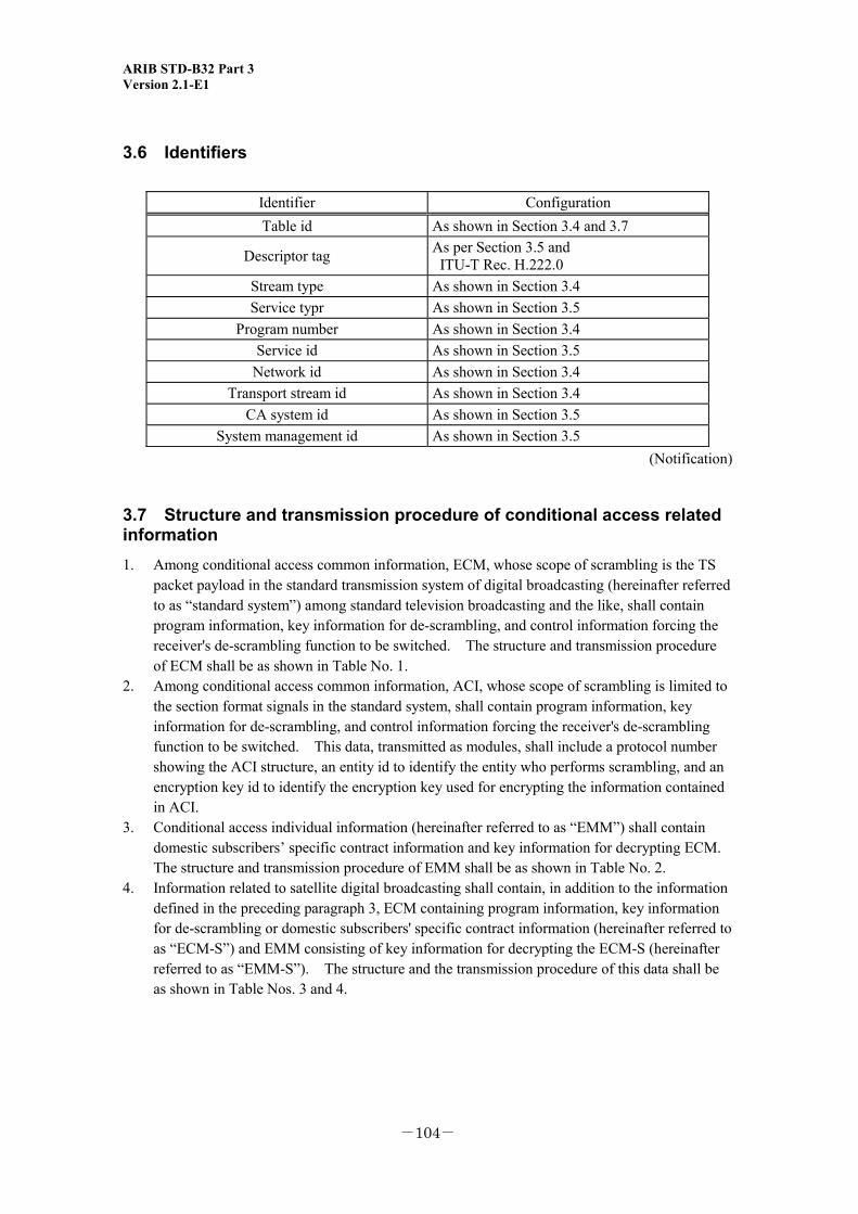
ARIB STD-B32 Part 3 Version 2.1-E1
-104-
3.6 Identifiers
Identifier Configuration Table id As shown in Section 3.4 and 3.7
Descriptor tag As per Section 3.5 and ITU-T Rec. H.222.0
Stream type As shown in Section 3.4 Service typr As shown in Section 3.5
Program number As shown in Section 3.4 Service id As shown in Section 3.5
Network id As shown in Section 3.4 Transport stream id As shown in Section 3.4
CA system id As shown in Section 3.5 System management id As shown in Section 3.5
(Notification)
3.7 Structure and transmission procedure of conditional access related information 1. Among conditional access common information, ECM, whose scope of scrambling is the TS
packet payload in the standard transmission system of digital broadcasting (hereinafter referred to as “standard system”) among standard television broadcasting and the like, shall contain program information, key information for de-scrambling, and control information forcing the receiver's de-scrambling function to be switched. The structure and transmission procedure of ECM shall be as shown in Table No. 1.
2. Among conditional access common information, ACI, whose scope of scrambling is limited to the section format signals in the standard system, shall contain program information, key information for de-scrambling, and control information forcing the receiver's de-scrambling function to be switched. This data, transmitted as modules, shall include a protocol number showing the ACI structure, an entity id to identify the entity who performs scrambling, and an encryption key id to identify the encryption key used for encrypting the information contained in ACI.
3. Conditional access individual information (hereinafter referred to as “EMM”) shall contain domestic subscribers’ specific contract information and key information for decrypting ECM. The structure and transmission procedure of EMM shall be as shown in Table No. 2.
4. Information related to satellite digital broadcasting shall contain, in addition to the information defined in the preceding paragraph 3, ECM containing program information, key information for de-scrambling or domestic subscribers' specific contract information (hereinafter referred to as “ECM-S”) and EMM consisting of key information for decrypting the ECM-S (hereinafter referred to as “EMM-S”). The structure and the transmission procedure of this data shall be as shown in Table Nos. 3 and 4.
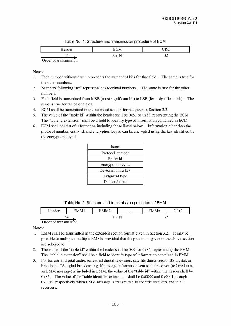
ARIB STD-B32 Part 3 Version 2.1-E1
-105-
Table No. 1: Structure and transmission procedure of ECM
Header ECM CRC 64
Order of transmission 8 × N 32
Notes: 1. Each number without a unit represents the number of bits for that field. The same is true for
the other numbers. 2. Numbers following “0x” represents hexadecimal numbers. The same is true for the other
numbers. 3. Each field is transmitted from MSB (most significant bit) to LSB (least significant bit). The
same is true for the other fields. 4. ECM shall be transmitted in the extended section format given in Section 3.2. 5. The value of the “table id” within the header shall be 0x82 or 0x83, representing the ECM.
The “table id extension” shall be a field to identify type of information contained in ECM. 6. ECM shall consist of information including those listed below. Information other than the
protocol number, entity id, and encryption key id can be encrypted using the key identified by the encryption key id.
Items Protocol number
Entity id Encryption key id De-scrambling key
Judgment type Date and time
Table No. 2: Structure and transmission procedure of EMM
Header EMM1 EMM2 … EMMn CRC 64
Order of transmission 8 × N 32
Notes: 1. EMM shall be transmitted in the extended section format given in Section 3.2. It may be
possible to multiplex multiple EMMs, provided that the provisions given in the above section are adhered to.
2. The value of the “table id” within the header shall be 0x84 or 0x85, representing the EMM. The “table id extension” shall be a field to identify type of information contained in EMM.
3. For terrestrial digital audio, terrestrial digital television, satellite digital audio, BS digital, or broadband CS digital broadcasting, if message information sent to the receiver (referred to as an EMM message) is included in EMM, the value of the “table id” within the header shall be 0x85. The value of the “table identifier extension” shall be 0x0000 and 0x0001 through 0xFFFF respectively when EMM message is transmitted to specific receivers and to all receivers.
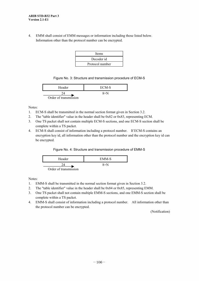
ARIB STD-B32 Part 3 Version 2.1-E1
-106-
4. EMM shall consist of EMM messages or information including those listed below. Information other than the protocol number can be encrypted.
Items Decoder id
Protocol number
Figure No. 3: Structure and transmission procedure of ECM-S
Header ECM-S
24 Order of transmission
8×N
Notes: 1. ECM-S shall be transmitted in the normal section format given in Section 3.2. 2. The "table identifier" value in the header shall be 0x82 or 0x83, representing ECM. 3. One TS packet shall not contain multiple ECM-S sections, and one ECM-S section shall be
complete within a TS packet. 4. ECM-S shall consist of information including a protocol number. If ECM-S contains an
encryption key id, all information other than the protocol number and the encryption key id can be encrypted.
Figure No. 4: Structure and transmission procedure of EMM-S
Header EMM-S
24 Order of transmission
8×N
Notes: 1. EMM-S shall be transmitted in the normal section format given in Section 3.2. 2. The "table identifier" value in the header shall be 0x84 or 0x85, representing EMM. 3. One TS packet shall not contain multiple EMM-S sections, and one EMM-S section shall be
complete within a TS packet. 4. EMM-S shall consist of information including a protocol number. All information other than
the protocol number can be encrypted. (Notification)

ARIB STD-B32 Part 3 Version 2.1-E1
-107-
<Blank Page>
ARIB STD-B32 Part 3 Version 2.1-E1
-108-
VIDEO CODING, AUDIO CODING, AND MUOTIPLEXING SPECIFICATIONS FOR
DIGITAL BROADCASTING
ARIB STANDARD
ARIB STD-B32 VERSION 2.1-E1 (March 14, 2007)
This Document is based on the ARIB standard of "Video Coding, Audio Coding, and Multiplexing Specifications for Digital Broadcasting" in Japanese edition and translated into English in May, 2007.
Published by
Association of Radio Industries and Businesses
Nittochi Bldg. 11F 1-4-1 Kasumigaseki, Chiyoda-ku, Tokyo 100-0013, Japan
TEL 81-3-5510-8590 FAX 81-3-3592-1103
Printed in Japan
All rights reserved


![Advanced Audio Coding [Aac]](https://static.fdocuments.in/doc/165x107/54689c1fb4af9ffe088b4a20/advanced-audio-coding-aac.jpg)