VICTORY WORKS, HEYWOOD, Greater Manchester Works Final Archaeological Report.pdfVICTORY WORKS,...
55
VICTORY WORKS, HEYWOOD, Greater Manchester Archaeological Watching Brief and Building Investigation Oxford Archaeology North December 2009 Countryside Properties (Northern) Ltd Issue No: 2009-10/1019 OA North Job No: L10037 NGR: SD 84645 10660
Transcript of VICTORY WORKS, HEYWOOD, Greater Manchester Works Final Archaeological Report.pdfVICTORY WORKS,...

VICTORY WORKS,
HEYWOOD,
Greater Manchester
ArchaeologicalWatching Brief andBuildingInvestigation
Oxford Archaeology North
December 2009
Countryside Properties(Northern) Ltd
Issue No: 2009-10/1019OA North Job No: L10037NGR: SD 84645 10660


Victory Works, Heywood, Greater Manchester: Archaeological Watching Brief and Building Investigation 1
For the use of Countryside Properties (Northern) Ltd © OA North: December 2009
CONTENTS
SUMMARY .....................................................................................................................2
ACKNOWLEDGEMENTS.................................................................................................3
1. INTRODUCTION .........................................................................................................4
1.1 Circumstances of Project....................................................................................4
1.2 Site Location ......................................................................................................5
2. METHODOLOGY........................................................................................................6
2.1 Objectives...........................................................................................................6
2.2 Watching Brief ...................................................................................................6
2.3 Archaeological Strip and Record .......................................................................6
2.4 Archive ..............................................................................................................7
3. BACKGROUND...........................................................................................................8
3.1 Introduction........................................................................................................8
3.2 Historical Background .......................................................................................8
3.3 Development of Victory Works.......................................................................10
4. RESULTS..................................................................................................................12
4.1 Introduction......................................................................................................12
4.2 Results of the watching Brief...........................................................................12
4.3 Results of Additional Building Investigation: Building A...............................17
4.4 Archaeological Strip and Record Excavation ..................................................26
5. CONCLUSION...........................................................................................................31
5.1 Watching Brief .................................................................................................31
5.2 Additional Building Investigation....................................................................32
5.3 Strip and Record Excavation............................................................................33
6. BIBLIOGRAPHY .......................................................................................................34
Cartographic Sources ..................................................................................................34
Primary Sources ..........................................................................................................34
Secondary Sources ......................................................................................................35
APPENDIX 1: PROJECT SPECIFICATION.....................................................................36
ILLUSTRATIONS ..........................................................................................................42

Victory Works, Heywood, Greater Manchester: Archaeological Watching Brief and Building Investigation 2
For the use of Countryside Properties (Northern) Ltd © OA North: December 2009
SUMMARY
In response to a request from Scott Wilson Ltd, acting on behalf of CountrysideProperties (Northern) Ltd, Oxford Archaeology North (OA North) undertook aprogramme of archaeological work at a former textile mill known as Victory Works,situated in Heywood, Greater Manchester (centred at NGR SD 84645 10660). In thefirst instance, this comprised a watching brief that monitored earth-moving works inthe area of the former boiler house, situated immediately to the west of the mainspinning block, and was carried out in June 2008. During the course of the watchingbrief, some additional measured survey of the spinning block was carried out toinform the results obtained from the watching brief. The second phase ofarchaeological work was carried out in November 2009, following the finaldemolition of the spinning block and clearance of the site, and comprised a ‘strip andrecord’ exercise. This was targeted on the western side of the spinning block, whichhad incorporated an internal engine house.
The watching brief revealed the well-preserved remains of two boiler beds,comprising three developmental phases of the steam-raising plant. The initial phase,representing the earliest use of the mill in the 1850s, utilised a Cornish-type boiler togenerate the steam required by the engine situated in the main spinning block.Surviving features in the fabric of the building, coupled with the results obtained fromthe ‘strip and record’, demonstrated that the mill had been powered originally by abeam engine, which had almost certainly been compounded. The engine flywheel wasplaced centrally, and the power was transmitted via a pinion wheel to the primarydrive shaft that was situated along the northern edge of the engine room. This shaftpowered the weaving shed to the north of the engine room, and was translated through90° into the spinning block at ground floor level via a bevel gear housed in the roomto the south of the engine. This room also housed a footstep bearing for the verticalshaft, carrying power to the upper floors of the spinning block, where the line shaftingwas supported on the southern of the two rows of columns. The primary shaft alsoappears to have serviced a pump, located in a small structure to the south of thespinning block, which appears to have returned water to the reservoir from a culvert,aligned under the building to the engine room.
This system was augmented in the late nineteenth century with the addition of at leastone Lancashire boiler to the west of the original Cornish-type boiler. The two boilerswere seemingly used concurrently, and were connected to a new cylindrical chimney,erected at the southern end of the original boiler.
The final phase of development was probably associated with the conversion of themill to electric drive in the early twentieth century, rendering the steam-power plantlargely redundant. The Lancashire boiler was decommissioned, its foundationbackfilled and the area flagged over to provide a storage area below offices at first-floor level in the boiler house. The original Cornish-type boiler, however, appears tohave been retained, presumably used to heat the mill complex.

Victory Works, Heywood, Greater Manchester: Archaeological Watching Brief and Building Investigation 3
For the use of Countryside Properties (Northern) Ltd © OA North: December 2009
ACKNOWLEDGEMENTS
Oxford Archaeology North (OA North) would like to thank Helen Lewis, ofCountryside Properties (Northern) Ltd, and Laura Broughton, of Scott Wilson Ltd, forcommissioning and supporting the project. Thanks are also due to Norman Redheadof the Greater Manchester Archaeological Unit for considerable support and advice.Further thanks are expressed to Sam Lane-Ryan, of Celtic Technologies, for logisticalassistance.
The watching brief was carried out by Will Gardner, Ellen McInnes and Chris Wild,the strip and record by Sean McPhillips, Kelly Clapperton and Graham Mottershead,and the drawings were produced by Marie Rowland and Chris Wild. The report wascompiled by Chris Wild and edited by Ian Miller, who was also responsible forproject management.

Victory Works, Heywood, Greater Manchester: Archaeological Watching Brief and Building Investigation 4
For the use of Countryside Properties (Northern) Ltd © OA North: December 2009
1. INTRODUCTION
1.1 CIRCUMSTANCES OF PROJECT
1.1.1 Countryside Properties (Northern) Ltd has submitted a planning application toredevelop a site for housing in Heywood, Greater Manchester. Until recently,the site was occupied by the Victory Works, which was established in the1850s as an integrated spinning and weaving mill, known as Rose Hill Mill.The development proposal allowed for the demolition of the mill complex, andthe complete clearance of the site.
1.1.2 In order to secure archaeological interests, Rochdale Metropolitan BoroughCouncil (RMBC) requested that an appropriate scheme of archaeologicalinvestigation was implemented in advance of demolition to ensure that anadequate record of the mill complex was compiled to mitigate its ultimate loss.Following consultation with the County Archaeologist for Greater Manchester,who provides RMBC with planning advice on archaeological issues, it wasrecommended that demolition was preceded by a programme of buildingrecording commensurate with an English Heritage Level 2-type survey.
1.1.3 The building recording was carried out by Scott Wilson Ltd on behalf ofCountryside Properties (Northern) Ltd, and concluded that the mill had anunusual plan form, reflecting its piecemeal development (Scott Wilson Ltd2008). However, as a result of fire damage, a former boiler house and part ofthe original spinning block were considered too dangerous to enter, and wereexcluded from the survey. Consequently, it was recommended that a watchingbrief was targeted on these areas during demolition and the subsequentremoval of modern surfacing. This was intended to identify any archaeologicalremains that were exposed, and compile a mitigation record in advance of theirultimate destruction. The scope of the required archaeological works waspresented in a project specification (Appendix 1), devised by Scott Wilson Ltdin consultation with the County Archaeologist for Greater Manchester.
1.1.4 In June 2008, Oxford Archaeology North (OA North) was requested by ScottWilson Ltd, acting on behalf on Countryside Properties (Northern) Ltd, tocarry out the specified programme of archaeological works during thedemolition and clearance of the site. In the first instance, the watching briefmonitored the removal of a modern concrete slab inside the former boilerhouse. Whilst undertaking the watching brief, significant archaeological detailwas observed within the spinning block to the east and, consequently, this wasalso rapidly recorded, in order to more fully explain the nature of the powersystem within the complex. Following the demolition of the former spinningblock, a second phase of archaeological works was implemented in November2009. Following consultation with the County Archaeologist for GreaterManchester, this final phase of archaeological investigation comprised aprogramme of strip and record, and was intended to identify and record anyarchaeological remains of the former engine room that had been internal to thespinning block.
Victory Works, Heywood, Greater Manchester: Archaeological Watching Brief and Building Investigation 5
For the use of Countryside Properties (Northern) Ltd © OA North: December 2009
1.2 SITE LOCATION
1.2.1 Victory Works is situated in Heywood, Greater Manchester (centred at NGRSD 84645 10660). Heywood is situated on the south bank of the River Roch,between Bury and Rochdale, and some 12km to the north of Manchester.
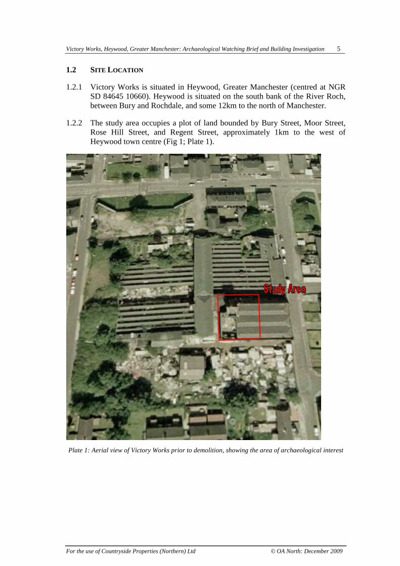
1.2.2 The study area occupies a plot of land bounded by Bury Street, Moor Street,Rose Hill Street, and Regent Street, approximately 1km to the west ofHeywood town centre (Fig 1; Plate 1).
Plate 1: Aerial view of Victory Works prior to demolition, showing the area of archaeological interest

Victory Works, Heywood, Greater Manchester: Archaeological Watching Brief and Building Investigation 6
For the use of Countryside Properties (Northern) Ltd © OA North: December 2009
2. METHODOLOGY
2.1 OBJECTIVES
2.1.1 The stated objectives of the archaeological works were:
• to identify and record the presence/absence, nature, extent, and date ofany archaeological deposits or features associated with the mill.Specifically, the watching brief was intended to record any structuresrevealed during the removal of fire-damage debris and the floor surface;
• to identify areas associated with the original power sources of theoriginal mill. These original power sources include the chimney base,flues, original boiler house and engine beds. It was intended that anyevidence for the early power structures would compliment the existingbuildings survey, and further enhance the current knowledge of thisstructure.
2.2 WATCHING BRIEF
2.2.1 A programme of field observation recorded the location, extent, and characterof all surviving archaeological features and deposits within the proposedground disturbance. The work comprised observations during the clearance ofa former boiler house and spinning block that contained an internal engineroom.
2.2.2 All excavation work was carried out using a mechanical excavator fitted witha toothless ditching bucket, which was operated under close archaeologicalsupervision. Any subsoil horizons exposed during the course of the groundworks were examined systematically, and all archaeological features andhorizons were recorded on OA North pro-forma recording sheets.
2.3 ARCHAEOLOGICAL STRIP AND RECORD
2.3.1 A final phase of field observation provided for a rapid identification andrecording of features below the floor level of the engine house. The workcomprised the removal of overburden within a single trench. All excavationwork was carried out using a mechanical excavator fitted with a toothlessditching bucket, which was operated under close archaeological supervision.Any subsoil horizons exposed during the course of the ground works weresystematically examined, and all archaeological features and horizons wererecorded on OA North pro-forma recording sheets.
Victory Works, Heywood, Greater Manchester: Archaeological Watching Brief and Building Investigation 7
For the use of Countryside Properties (Northern) Ltd © OA North: December 2009
2.4 ARCHIVE
2.4.1 The results of all archaeological work carried out will form the basis for a fullarchive to professional standards, in accordance with current English Heritageguidelines (Management of Archaeological Projects, 2nd edition, 1991).
2.4.2 The Arts and Humanities Data Service (AHDS) online database Online Accessto index of Archaeological Investigations (OASIS) will be completed as partof the archiving phase of the project.

Victory Works, Heywood, Greater Manchester: Archaeological Watching Brief and Building Investigation 8
For the use of Countryside Properties (Northern) Ltd © OA North: December 2009
3. BACKGROUND
3.1 INTRODUCTION
3.1.1 The following section provides an overview of the historical development ofthe site, and draws on the earlier assessment undertaken by Scott Wilson Ltd(2008, 4-8). The presentation of the historical background is intended toprovide a context for the results obtained from the archaeologicalinvestigation.
3.2 HISTORICAL BACKGROUND
3.2.1 Throughout the medieval and post-medieval periods, Heywood almostcertainly comprised little more than a small farming community. It is likelythat the incomes derived from farming will have been supplemented byweaving woollen goods in the domestic system (Baines 1835). By thesixteenth century, the textile industries in south Lancashire were beginning toflourish. Woollen cloths made from fleeces were being produced on thePennine slopes to the north and east of Manchester, including the area aroundHeywood, and coarse linens were being woven, and bleached and dyed, fromlocally-grown flax and hemp on the plain to the west (Winterbotham 1998,22). During this period, Walloons fleeing the Low Countries and Huguenotsescaping persecution in France sought refuge in England. They brought theirlooms and their weaving trade, and specialised in making complicated threadsand tapes. They settled initially in the south, in Canterbury and London, butsoon transferred their trade to the Manchester area, a move presumablystimulated by the lack of regulation and guilds (Wadsworth and Mann 1931,102). This workforce, using complicated and expensive Dutch looms, gave toManchester a skilled and industrialised workforce, and perhaps unwittinglyhelped to establish an industrial discipline needed with the turn to factoryproduction that was to have a dramatic impact on the whole region.
3.2.2 By this time, the weaving of pure woollens in south Lancashire had started todecline in favour of mixed fabrics classed as smallwares and fustians, whilstthe market for linen remained buoyant. Linen yarn formed the warp for bothfabrics, and whilst worsted was usually selected for the weft in smallwares,cotton became frequently used in fustians; the earliest known reference tocotton in the region dates to 1601, when it was mentioned in the will ofGeorge Arnould, a Bolton fustian weaver (Wadsworth and Mann 1931, 15).Fustians were produced in a network of towns with Manchester at their hub,and the town became the principal commercial centre for the region(Winterbotham 1998, 40).
3.2.3 It was against this background that Heywood developed and expanded in thenineteenth century as one of the many satellite towns around Manchesterengaged in the manufacture of textile goods. Heywood, situated on the RiverRoch, and with an abundance of local coal, was well suited to the newindustry, and the first cotton-spinning factory, Makin Mill, was established in

Victory Works, Heywood, Greater Manchester: Archaeological Watching Brief and Building Investigation 9
For the use of Countryside Properties (Northern) Ltd © OA North: December 2009
the town in 1770 (Haynes 1997). The earliest factories were water-powered,and several were erected on sites in the Cheesden Valley (McNeil and Nevell2000, 35). However, the industry developed only slowly during the earlynineteenth century, with only ten mills in 1817, although by 1833 the total hadrisen to 27.
3.2.4 The industry expanded more rapidly following the improvement to the localtransport network, primarily with the construction of the Heywood BranchCanal in 1834 (Hadfield and Biddle 1970), and, more importantly, theLancashire and Yorkshire railway in 1848 (Nock 1969). The resultant‘extraordinary growth of the cotton trade’ in Heywood during the mid-nineteenth century led to ‘an influx of strangers causing a very densepopulation’ (Lewis 1848). Indeed, Edwin Waugh, the Rochdale-born poet,was able to describe Heywood in the early 1880s as ‘almost entirely thecreation of the cotton industry’. In 1881, the newly created MunicipalBorough of Heywood included 67 cotton mills and weaving sheds, togetherwith 75 cotton waste and other textile warehouses, and 67 engineering works,the bulk of which produced machines for the textile industry.
3.2.5 By the late nineteenth century, Heywood established itself as a centre for theproduction of low-grade cloth from cotton waste, a process which differedonly in the preparatory phase from normal cotton spinning, and thus requiredlittle conversion for the existing mills. However, the limited amount of wasteavailable restricted the trade and thus the size of the individual mills (Williamswith Farnie 1992, 15). Nevertheless, in 1905, Plum Tickle Mill in Heywoodbegan operation as the largest mule-spinning mill in the world under one roof(Haynes 1997).
3.2.6 Production in Heywood reached its zenith as a textile-manufacturing town in1915, when the cotton-spinning mills in the town housed in excess of1,000,000 spindles, making the town the fifteenth largest centre of cottonspinning in the region (Williams with Farnie 1992, 44-7). However, the Thelast large weaving mill in the town was J Smith Hargreaves & Company,towel manufacturers.
3.2.7 As elsewhere in the region, decline in the subsequent decades was rapid, withmany of the mills closing and being demolished. Plum Mill and its sister-mill,Unity Mill, were idled in the 1960s under the government reorganisation ofthe cotton industry. By the mid-1960s, only two spinning mills remained inoperation (The Rochdale Directory 1966, 132). Since then, most of the formercotton mills in the town have been demolished, although the Mutual Mills, acomplex of four spinning factories, are Grade II listed buildings, and provide aphysical reminder of the importance of the textile industry to the town.

Victory Works, Heywood, Greater Manchester: Archaeological Watching Brief and Building Investigation 10
For the use of Countryside Properties (Northern) Ltd © OA North: December 2009
3.3 DEVELOPMENT OF VICTORY WORKS
3.3.1 The site of Victory Works lies on the margins of the town of Heywood, and assuch was outside the initial industrial development of the town in the earlynineteenth century. The site is depicted on the Ordnance Survey first edition1:10,560 map of 1851 as enclosed agricultural land, situated to the south ofBury Street, the principal route between Heywood and Bury.
3.3.2 The mill had evidently been erected by 1858, as it is listed as Rose Hill Mill ina trade directory for that year. At that date, the mill was occupied by CharlesWelsh, who is listed as a cotton spinner and manufacturer (Slater 1858, 158).However, by 1861, John Coupe had taken over operation at the mill, and by1882 he had formed a limited company ‘John Coupe & Co Ltd’ (Slater 1882,286). In 1888, John Coupe & Co, of Rose Hill Mill, was fined for running themill after hours, in contravention of the Factory Act (Manchester Times 25February 1888). The firm is listed at Rose Hill Mill in a directory for 1891,and accredits them with operating 9,996 spindles and 573 looms to producetwill, satins, and velvets (Worrall 1891, 107).
3.3.3 The complex is first depicted cartographically on the 1891 1:500 and 18931:2500 Ordnance Survey maps (Plate 2). The plan form of the mill complex isshown to be similar to the final layout; it is roughly rectangular in plan, withan alleyway projecting into the building from the east elevation, and a furtherstructure projecting to the north. This represents a series of inter-linkedbuildings, and the complex is labelled ‘Rose Hill Mill’. A chimney is locatedcentrally along the south elevation, with two rectangular reservoirs situated inthe south-east corner of the site.
Plate 2: Extract from the Ordnance Survey first edition 1:2500 map of 1893

Victory Works, Heywood, Greater Manchester: Archaeological Watching Brief and Building Investigation 11
For the use of Countryside Properties (Northern) Ltd © OA North: December 2009
3.3.4 The subsequent Ordnance Survey editions of 1910 and 1929-30 1:2500 displaythe same plan layout within the complex. Although the surrounding area hadbeen subject to some development, the mill remained close to the south-western limit of the town. Some detail is provided about the mill in Worrall’sCotton Spinners’ and Manufacturers’ Directory of 1918. This lists the millunder John Coupe & Co, and states that the mill housed 9,996 mule spindlesand 635 looms, producing satteens, jeanettes, plains and proofing cloths, andrepresenting an increase in the number of looms since 1891. The firm is alsolisted under cotton spinners and manufacturers in a trade directory for 1924(Kelly 1924, 1692).
3.3.5 The Ordnance Survey third edition 1:2500 map of 1937 depicts the mill withlargely the same plan layout, although the buildings are labelled as 'disused'.The site is divided into roughly two parts, along a north/south axis. This mayreflect the division of the building into two discrete operational units, orsimply the division between buildings on site (Scott Wilson Ltd 2008).Terraced housing is also shown to have been constructed on open land to thesouth of the site.
3.3.6 The 1955-56 1:10,560 Ordnance Survey map labels the mill as Rose Hill Mill.However, the 1956-1957 1:1250 Ordnance Survey map labels the majority ofthe mill as Victory Works (Paper Tubes), whilst the north-east corner islabelled ‘Cotton Waste Mill’. The boundary between these two factories runsalong the north/south division seen previously on the 1937 Ordnance Surveymap. No division is shown between the two terraced properties to the north-east of the site, suggesting that these may have been interconnected at thispoint (ibid). An electricity sub-station had been erected along the eastelevation of the building by that date, whilst a further square structure has beenconstructed to the south of the site.
3.3.7 The 1970 1:1250 Ordnance Survey map shows a similar arrangement to thesite, which is still divided into the two operational units. However, by 1977,the central portion of the building to the west of the site has been demolished,so that an east/west-aligned alleyway now extends across the full extent ofVictory Works. By this time the chimney along the southern elevation of themill had been demolished, and the reservoirs had been infilled.

Victory Works, Heywood, Greater Manchester: Archaeological Watching Brief and Building Investigation 12
For the use of Countryside Properties (Northern) Ltd © OA North: December 2009
4. RESULTS
4.1 INTRODUCTION
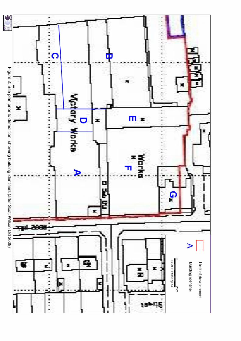
4.1.1 The foundations of the boiler house (Building D), situated immediately to thewest of the main spinning block (Building A; Fig 2), were exposed during thedemolition and clearance of the standing structure in June 2008. All earth-moving works carried out in this part of the site subsequently were monitoredby an archaeological watching brief. During the course of the watching brief,the buried remains of the boiler house were exposed directly beneath themodern floor in the eastern part of the former building.
4.1.2 The interior of Building D had been remodelled prior to demolition, and itslatest flooring comprised a concrete slab, up to 0.3m thick (Scott Wilson Ltd2008). This sealed a mixed deposit of brick rubble and fuel waste, whichvaried in depth from 0.2m to 2.0m. Extant brick-built remains wereencountered at a depth of 0.5m below the top of the concrete slab. A 25-tontracked excavator with a toothed bucket exposed the upper surfaces, afterwhich all surviving buried structural remains were excavated by hand.
4.2 RESULTS OF THE WATCHING BRIEF
4.2.1 Phase 1 (c 1858): the earliest fabric within the boiler house pertained to thebed of a Cornish-type boiler (Plate 3). The remains were well-preserved,possibly as a result of its apparent continued maintenance into Phase 3, andcomprised a floor of hand-made red brick, aligned broadly north/south, andmeasuring 31ft (9.44m) long by 10ft (3.04m) wide (Fig 3).
Plate 3: Bed of Phase 1 Cornish boiler

Victory Works, Heywood, Greater Manchester: Archaeological Watching Brief and Building Investigation 13
For the use of Countryside Properties (Northern) Ltd © OA North: December 2009
4.2.2 The bricks forming the floor of the boiler bed appeared to have been bondedwith clay, rather than lime-based mortar, possibly to prevent moisture rising.The boiler benches survived to their full original height of 2ft (0.61m), andwere constructed ofhand-made red brick,faced with a singleskin of yellowrefractory brick (Plate3), all bonded with amid-brown lime-based mortar. Theupper surface of thebenches formed thebase of the flues,which routed exhaustgases along the sideof the boiler to linkinto the main flue tothe chimney at therear of the boiler.Numerous boiler-mounting blocks,moulded fromrefractory clay (Plate4), survived in-situ,with further examplesrecovered from thedemolition materialthat had beenbackfilled. Plate 4: Detail of boiler mounting blocks and the side flue
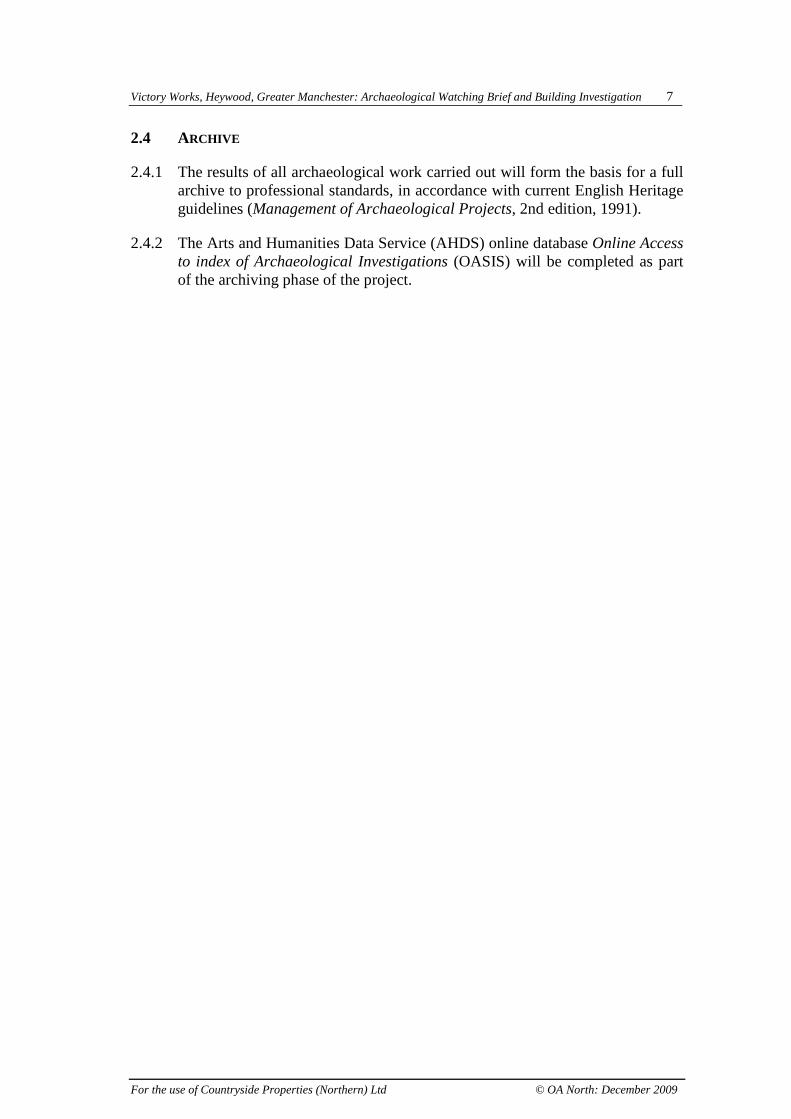
4.2.3 Whilst the boiler was linked eventually into the base of the circular Phase 2chimney by a flue at its southern end, this represented a remodelling of theoriginal flue. This early structure turned eastwards into the original square-section chimney, placed in the south-west corner of the spinning block (Fig 3)and survived extant as a short cylindrical stack above the mill in the 1980s,when it was photographed (Plate 5) during the Greater Manchester TextileMill Survey (Williams with Farnie 1992). Similarly, the boiler chargingplatform, steam pipe and blow-down, positioned at the northern end of theboiler, also represented later alterations to the features within the originalboiler house.
Victory Works, Heywood, Greater Manchester: Archaeological Watching Brief and Building Investigation 14
For the use of Countryside Properties (Northern) Ltd © OA North: December 2009
Plate 5: Aerial photo of Victory Works dating from the 1980s (Williams with Farnie 1992)
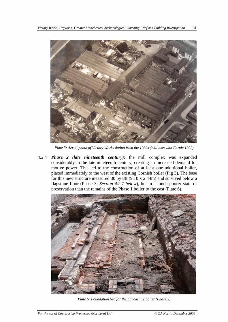
4.2.4 Phase 2 (late nineteenth century): the mill complex was expandedconsiderably in the late nineteenth century, creating an increased demand formotive power. This led to the construction of at least one additional boiler,placed immediately to the west of the existing Cornish boiler (Fig 3). The basefor this new structure measured 30 by 8ft (9.10 x 2.44m) and survived below aflagstone floor (Phase 3; Section 4.2.7 below), but in a much poorer state ofpreservation than the remains of the Phase 1 boiler to the east (Plate 6).
Plate 6: Foundation bed for the Lancashire boiler (Phase 2)

Victory Works, Heywood, Greater Manchester: Archaeological Watching Brief and Building Investigation 15
For the use of Countryside Properties (Northern) Ltd © OA North: December 2009
4.2.5 The benches supporting the boiler survived to a maximum height of twocourses, and were faced with refractory brick and bonded with a mid-brownlime-based mortar. The partial survival of a full-brick thickness centraldividing wall at the rear of the boiler (Plate 6) indicates that it was of aLancashire type. It seems likely, from the above-ground structures recordedduring the building recording (Scott Wilson Ltd 2008), that another Lancashireboiler lay to the west of the watching brief area, serving a new engine house(Building C; Fig 2), constructed to supply power to a new Phase 2 weavingshed (Building B; Fig 2).
4.2.6 The new boilers utilised a new cylindrical chimney (Plate 7), placedimmediately to the south of the Phase 1 Cornish boiler (Fig 3), adjacent to theexisting chimney, but projecting beyond the south wall of the mill, as shownon the Ordnance Survey edition of 1893 (Plate 2). It had an internal diameterof 5 ft (1.52m), constructed of red brick, and faced internally with a single skinof yellow refractory brick. Evidence for valves within the remodelled flue tothe Phase 1 boiler was observed (Plate 7), but was only fragmentary in nature,and it was thus not possible to confirm its design.
Plate 7: Exposed remains of the Phase 2 chimney
4.2.7 Phase 3 (early twentieth century): Building D (the boiler house) wasremodelled significantly during the early twentieth century, an episode whichalmost certainly related to the introduction of an electrical power supply to themajority of the mill complex. The Lancashire boiler in the western part of thebuilding was removed and its flue decommissioned, with the base of the bedsealed with sandstone flags subsequently (Plate 8). A central wall of verticallyset flagstones was incorporated within the re-floored boiler bed (Fig 4|),suggesting that the area was converted to sub-floor storage tanks for powdersor other solid materials.

Victory Works, Heywood, Greater Manchester: Archaeological Watching Brief and Building Investigation 16
For the use of Countryside Properties (Northern) Ltd © OA North: December 2009
Plate 8: Dividing wall within the Phase 3 floor over the site of the Lancashire boiler
4.2.8 The original Cornish boiler appears to have been retained in service,presumably to provide heat for the mill complex. The charging platform at thefront of this boiler (Plate 9), and the associated ‘blow down’, were constructedusing a dark ash-based mortar, indicating that they almost certainly dated fromthis period, replacing earlier examples.
Plate 9: Remodelled ‘blow down’ and charging platform of Cornish boiler

Victory Works, Heywood, Greater Manchester: Archaeological Watching Brief and Building Investigation 17
For the use of Countryside Properties (Northern) Ltd © OA North: December 2009
4.3 RESULTS OF ADDITIONAL BUILDING INVESTIGATION: BUILDING A
4.3.1 Introduction: during the watching brief, it was noted that additionalinformation to that contained within the original building recording (ScottWilson Ltd 2008), was visible within Building A. This structural fabric relateddirectly to the power systems within the mill, and was thus considered relevantto the excavations of the associated boiler.
4.3.2 Ground Floor: the eastern eight bays of the ground floor comprised an open-plan preparation area, with the plastered ceiling supported by timber beamsand cylindrical section cast-iron columns at each bay division. The beamswere strengthened within each bay with channel-section cast-iron flitch plates,and deflection within their span suggests that they may have been jointedabove the columns, with each bay division comprising three members. Thecolumns were oftypical mid-nineteenth centurystyle, but alsoincluded integralload-transfer boxesfor the timber beamswithin the columnhead (Plate 10),possibly to protectany such joint. Atground floor level,the columns did notincorporate castingsfor carrying the lineshaft, which waspositioned further tothe south (seebelow). However,within the easternpart of the building,where the first floorhad been removed,for the late insertionof a travelling hoist,line shaft hangercastings could beobserved clearly onthe southern faces ofthe southern of thetwo rows of columnsat first-floor level(Plate 11). Plate 10: Cast-iron column head detail, second floor, Building A

Victory Works, Heywood, Greater Manchester: Archaeological Watching Brief and Building Investigation 18
For the use of Countryside Properties (Northern) Ltd © OA North: December 2009
Plate 11: Line shaft hanger casting in column head, first floor, Building A
4.3.8 The western two bays of the spinning block contained significant detail ofarchaeological importance. The building recording noted apertures relating tothe engine house in the brick wall dividing these two bays from the main millarea, and two large apertures to the south that were interpreted as housings forventilation fans (Scott Wilson Ltd 2008, 13). However, these features almostcertainly represented elements of the power transmission system.
4.3.9 The northern apertures, relating to the engine, were framed with substantialdressed sandstone blocks (Plate 12), and housed the framing and aperture for apinion wheel located against the northern wall of the engine house. A largebearing box to the immediate north was partially obscured behind/above a lateclinker block structure in the north-western corner of the main ground floorarea of the building. To the south, immediately adjacent to the southern row ofcolumns, a very large bearing box was placed at ceiling level. This bearingbox was 5’4” wide (1.62m), and had iron sheeting behind a redundant brackethousing on its eastern face (Plate 13). Brick blocking was visible behind thissheeting and, unlike that blocking the apertures to the north, this utilised alime-based mortar, indicative of a mid-nineteenth-century date, and waspossibly contemporary with the original construction of the bearing box.Examination of the western face of the wall (Section 4.3.5, below) revealedthat the box housed the footstep bearing of the upright driveshaft on itswestern side. It would have been impractical to include a shaft into the groundfloor in this position, given the nature of the bevel gear involved to translatethe driveshaft vertically through 90º, thus explaining the rationale of enclosingthe rear of the bearing box.

Victory Works, Heywood, Greater Manchester: Archaeological Watching Brief and Building Investigation 19
For the use of Countryside Properties (Northern) Ltd © OA North: December 2009
Plate 12: Pinion wheel framing, and bearing box, ground floor, Building A
Plate 13: Rear of footstep bearing, ground floor, Building A
4.3.10 The smaller, 3’6” (1.07m) bearing box to the south, again placed at ceilinglevel, represents the position of the line shafting within the ground floor of themain mill. It is unusual for such a bearing box to incorporate shuttering on itseastern face, and whilst this does retain a central aperture which a small lineshaft may have passed, it more probably represents a later addition to the box,as it includes apertures for both electrical cable ducting and water pipingrelating to the sprinkler system (Plate 14), both of which would probably havebeen introduced in the first two decades of the twentieth century.

Victory Works, Heywood, Greater Manchester: Archaeological Watching Brief and Building Investigation 20
For the use of Countryside Properties (Northern) Ltd © OA North: December 2009
Plate 14: Shuttering on bearing box
4.3.11 The southern half of the western two bays were of fireproof construction, witha north/south-aligned brick-vaulted ceiling (Figs 6 and 7; Plate 15). This wasstrengthened at regular intervals with iron tie-rods through the vaulting (Fig5). The internal vaulting was carried on a cast-iron beam, probably T-sectionin profile, which was supported by a single cylindrical section column, similarto those within the main mill building, but placed centrally within the roomand offset from those to the east. This had a line shaft carrier bracket on itswestern face (Plate 15), aligned with bearing boxes in the north and southelevations (Figs 5, 6, and 7), which would have housed the end bearings of ashort line shaft, installed specifically for this room.
Plate 15: Brick-vaulted ceiling and line shaft carrier bracket, Building A

Victory Works, Heywood, Greater Manchester: Archaeological Watching Brief and Building Investigation 21
For the use of Countryside Properties (Northern) Ltd © OA North: December 2009
Plate 16: Main footstep bearing, blocked upright shaft aperture and drum cutaway
4.3.7 The north elevation contained two further apertures: a housing with asandstone sill and lintel (Fig 6) for an engine mounting, located in the room tothe north; and a larger, 3’6” (1.07m) bearing box, flush with the east elevation(Fig 8; Plate 15), which carried the primary shaft from the engine to thefootstep bearing, positioned centrally in the east elevation (Fig 5). Both ofthese bearing boxes had cutaways within the wall face, for drums on thedriveshaft, allowing it to be positioned as close to the wall as possible. Abovethe footstep bearing mount (Plate 16), a blocked aperture in the ceilingpreviously housed the upright shaft, distributing rotative power to the upperfloors. A further bearing box in the east wall, to the south of the main bearing(Plate 17), would have housed a bevel gear, allowing the rotative power to betransferredthrough 90º intothe main millblock at groundfloor level,whilst alsoallowing themain driveshaftto continue tothe south,through theexternal southwall (Fig 7),where it wascarried into asmall structure tothe south(Section 4.4.3,below). Plate 17: Bearing box for bevel gear

Victory Works, Heywood, Greater Manchester: Archaeological Watching Brief and Building Investigation 22
For the use of Countryside Properties (Northern) Ltd © OA North: December 2009
4.3.8 Access into this room was originally at the southern end of the east wall,through a doorway from the main area of the ground floor (Fig 8). This had asegmental brick arch and a timber plank door, presumably replacing an earlierfireproof example. A doorway inserted at the western end of the southernelevation more recently provided external access into the room, with theoriginal window above presumably being blocked at this time (Fig 7). To thewest of this doorway, the wall had a boxed return to the west elevation. Thishoused the original chimney, the tapering cylindrical stack of which survivedinto the 1980s (Plate 5). No evidence for apertures into the flue were observed,although a void in the wall face (Fig 8) revealed that the chimney stack was ofa single-brick thickness (Fig 9), and was infilled with rubble. In the north-westcorner of the room, an aperture within the brick-vaulted ceiling originally ledto the first floor. It had an iron-sheet lining (Plate 18) and was covered/sealedat first-floor level with a similar sheet, presumably serving originally as aventilation shaft/flue.
Plate 18: Blocked aperture in vaulted ceiling
4.3.9 To the north of this room lay the engine house. It was arranged in a somewhatunusual style, with the engine aligned longitudinally within the mill, ratherthan the more common transverse position of an internal engine. No safeaccess was possible into the 2 x 1 bay structure, but details of the wall fixturesfor the vertical engine it housed could clearly be identified from the stairtower, positioned in the north-west corner of the mill (Plate 19). A doorway inthe south elevation at second floor level provided access to the room above theengine, whilst access to the engine house itself was afforded from the stairwellin the north-west corner, at ground floor level. Hoist rings survived within abadly burned ceiling beam, which had fallen into the debris of the enginehouse. These demonstrate how integral the structure of the engine house wasto its support, rather than the almost free-standing, later engines. Varioussandstone-lined apertures, mainly described above, were also observed withinthe walls of the engine house, demonstrating how it was largely supported bythe structural fabric of the building.

Victory Works, Heywood, Greater Manchester: Archaeological Watching Brief and Building Investigation 23
For the use of Countryside Properties (Northern) Ltd © OA North: December 2009
Plate 19: View into damaged engine house from stair tower
4.3.10 The large central aperture in the east wall represented the housing for theframing for a pinion wheel (Plate 20). The two outer apertures would havesupported the axle mount, whilst the central, much taller aperture, formed apartial cutaway into the wall, allowing the wheel to be positioned as closely aspossible to the wall. The large bearing box observed to the immediate north ofthe pinion wheel housing (Plates 12 and 20) was of very similar style to that inthe room to the south of the engine, suggesting that a bevel gear was alsohoused in this position, taking power from the primary shaft and translating itthrough 90° into the ground floor of the spinning block, providing a secondline shaft, to power machinery in the northern part of the ground floor.
Plate 20: Pinion wheel housing within engine house

Victory Works, Heywood, Greater Manchester: Archaeological Watching Brief and Building Investigation 24
For the use of Countryside Properties (Northern) Ltd © OA North: December 2009
4.3.11 First Floor: access to the first floor was via a fireproof stair tower, placed inthe north-west corner of the mill. It comprised sandstone flag floors and steps,and had a central rectangular-section brick newel, which housed a hoist (Plate21). The first floor was partitioned bya brick dividing wall, where theengine house continued at this level.No safe access was afforded to theroom on its southern side, which hada loading door in the southernelevation, suggesting materials werehoisted into this room This room alsohoused the vertical driveshaft, and alarge bearing box transferred powerinto the main floor area. The lineshaft was carried on hangers attachedto castings on the southern face onthe southern row of columns, andpresumably drove spinning mulesplaced transversely across the room.The room had a timber-plank floorand a whitewashed lath and plasterceiling, and was partitioned from theextension to the ground floor at theeastern end of the building by a studand chipboard partition. Plate 21: Hoist within the stair newel
4.3.12 The water supply for the sprinkler system did not utilise the newel of the stairtower, but instead rose between the floors adjacent to the second column in thenorthern row of columns (Plate 22). Smaller-section pipes directed the supplyaround the floor at ceiling level, hung from hangers attached to the beams.
Plate 22: First floor, Building A, with sprinkler pipe arrangement

Victory Works, Heywood, Greater Manchester: Archaeological Watching Brief and Building Investigation 25
For the use of Countryside Properties (Northern) Ltd © OA North: December 2009
4.3.13 Second Floor: the upper floor of the mill was of a similar open plan to the firstfloor, although it remained intact at the eastern end, above the ground- andfirst-floor alterations below. The three-span, east/west-aligned roof had itsvalleys positioned above the two rows of columns. However, the entire ceilingwas sealed with lath and plaster, covering the detail of the trusses, which werepresumably simple collared trusses, as there were neither queen or king postsin the open raised sections above the beams (Plate 23).
Plate 23: Second floor, Building A,
4.3.14 The bay to the immediate south of centre had an inserted taking-in door in thesouthern elevation, in the position of the original window, extending the doorto floor level. This had an I-section crane rail extending both externally, and tothe southern column internally, where a large mechanical hoist was situated.This appears to have been almost certainly driven by the line shaft, whichwould have been placed along the southern side of the adjacent column.
4.3.15 As at first floor level, no safe access was afforded into the western two bays ofthe second floor, although it was possible to observe a doorway in a dividingwall, which extended above the south wall of the engine house at this level.

Victory Works, Heywood, Greater Manchester: Archaeological Watching Brief and Building Investigation 26
For the use of Countryside Properties (Northern) Ltd © OA North: December 2009
4.4 ARCHAEOLOGICAL STRIP AND RECORD EXCAVATION
4.4.1 Introduction: following the demolition of the mill, an archaeological strip andrecord exercise was undertaken in the footprint of the western two bays ofBuilding A (Fig 10). Removal of the late twentieth-century concrete floorsrevealed the basal remains of the engine house, and associated culverts. All thestructural walls observed within the building survey continued below groundlevel, and thus the results can be discussed in relation to the stair tower, enginehouse, and the preparation room in the south-west corner of the mill.
4.4.2 Engine House: the sub-floor remains of the engine house comprised twodistinct areas. The western area had been significantly remodelled, housing atimber plank-capped machine-made brick culvert (Plate 24), whilst the easternend retained large sandstone blocks pertaining to the original engine (Fig 10).Four such blocks survived, comprising dressed sandstone piers, eachmeasuring approximately 4’ (1.21m) square and 18” (0.46m) thick. The north-western of the four blocks survived to an additional block’s height, level withthe remodelled flagstone/concrete floors to the west. Bolts for tying down theengine to the bed, were cut flush with its upper surface, suggesting that itformed part of this later floor, whilst the lower remaining piers had twisted andbent bolts projecting significantly from their upper surfaces (Plate 25). Thewestern two almost certainly supported the cylinders of the engine, whilstthose to the east would have housed columns supporting the entablature beamof the engine. The western end of the engine house would have contained avoid below floor level, providing an ideal space through which to place a laterculvert.
Plate 24: Remodelled western part of engine house

Victory Works, Heywood, Greater Manchester: Archaeological Watching Brief and Building Investigation 27
For the use of Countryside Properties (Northern) Ltd © OA North: December 2009
Plate 25: Engine bed, showing fixing bolts
4.4.3 Preparation Room: very few archaeological remains were observed beneaththe floor of thepreparation room to thesouth of the enginehouse (Fig 10).Fragmentary wire-cutbrick walls, bonded to asmall expanse ofconcrete floor, wereobserved in the north-west corner of the room,and appear to relate torelatively lateremodelling of theengine house. Thisoverlay a north/south-aligned wall, of 1½brick thickness, bondedwith a black sootymortar, indicative of alate nineteenth-centurydate. This formed theeastern wall of a conduithousing a 9” (0.23m)diameter cast-iron waterpipe (Plate 26). Plate 26: Cast-iron water pipe adjacent to the western wall
Victory Works, Heywood, Greater Manchester: Archaeological Watching Brief and Building Investigation 28
For the use of Countryside Properties (Northern) Ltd © OA North: December 2009
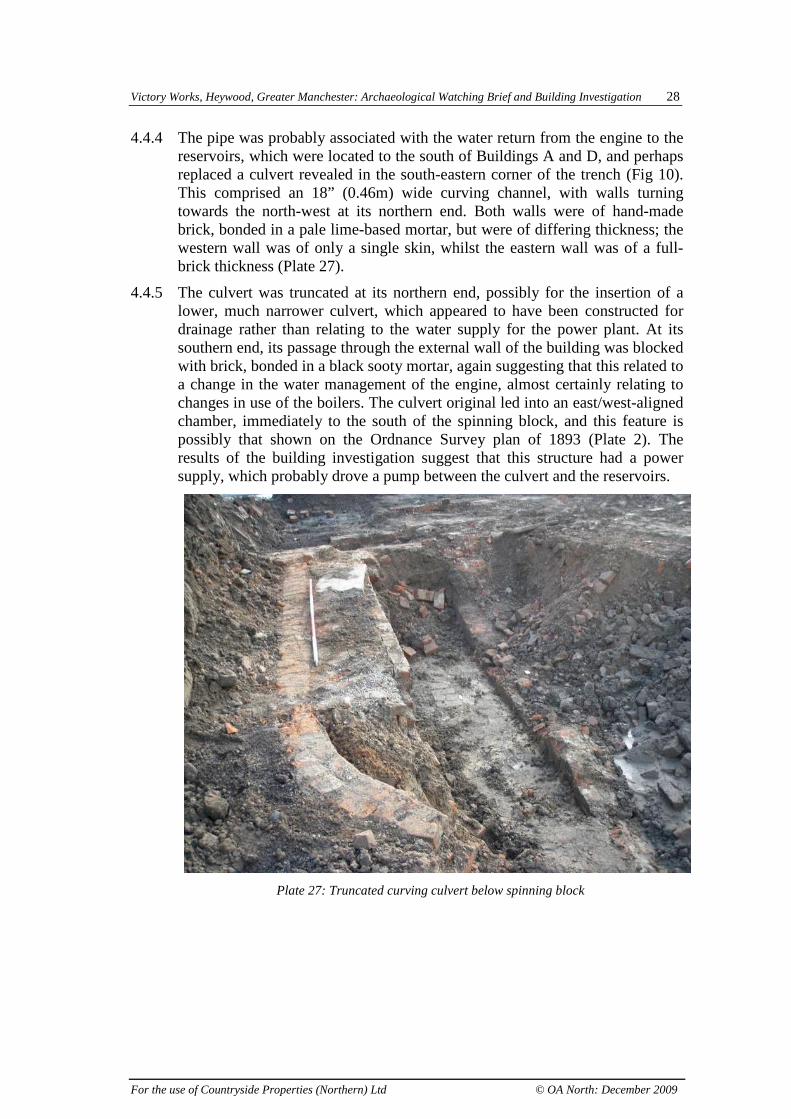
4.4.4 The pipe was probably associated with the water return from the engine to thereservoirs, which were located to the south of Buildings A and D, and perhapsreplaced a culvert revealed in the south-eastern corner of the trench (Fig 10).This comprised an 18” (0.46m) wide curving channel, with walls turningtowards the north-west at its northern end. Both walls were of hand-madebrick, bonded in a pale lime-based mortar, but were of differing thickness; thewestern wall was of only a single skin, whilst the eastern wall was of a full-brick thickness (Plate 27).
4.4.5 The culvert was truncated at its northern end, possibly for the insertion of alower, much narrower culvert, which appeared to have been constructed fordrainage rather than relating to the water supply for the power plant. At itssouthern end, its passage through the external wall of the building was blockedwith brick, bonded in a black sooty mortar, again suggesting that this related toa change in the water management of the engine, almost certainly relating tochanges in use of the boilers. The culvert original led into an east/west-alignedchamber, immediately to the south of the spinning block, and this feature ispossibly that shown on the Ordnance Survey plan of 1893 (Plate 2). Theresults of the building investigation suggest that this structure had a powersupply, which probably drove a pump between the culvert and the reservoirs.
Plate 27: Truncated curving culvert below spinning block
Victory Works, Heywood, Greater Manchester: Archaeological Watching Brief and Building Investigation 29
For the use of Countryside Properties (Northern) Ltd © OA North: December 2009
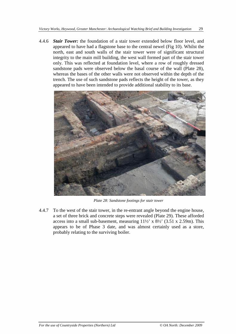
4.4.6 Stair Tower: the foundation of a stair tower extended below floor level, andappeared to have had a flagstone base to the central newel (Fig 10). Whilst thenorth, east and south walls of the stair tower were of significant structuralintegrity to the main mill building, the west wall formed part of the stair toweronly. This was reflected at foundation level, where a row of roughly dressedsandstone pads were observed below the basal course of the wall (Plate 28),whereas the bases of the other walls were not observed within the depth of thetrench. The use of such sandstone pads reflects the height of the tower, as theyappeared to have been intended to provide additional stability to its base.
Plate 28: Sandstone footings for stair tower
4.4.7 To the west of the stair tower, in the re-entrant angle beyond the engine house,a set of three brick and concrete steps were revealed (Plate 29). These affordedaccess into a small sub-basement, measuring 11½’ x 8½’ (3.51 x 2.59m). Thisappears to be of Phase 3 date, and was almost certainly used as a store,probably relating to the surviving boiler.

Victory Works, Heywood, Greater Manchester: Archaeological Watching Brief and Building Investigation 30
For the use of Countryside Properties (Northern) Ltd © OA North: December 2009
Plate 29: Steps into sub-basement adjacent to stair tower

Victory Works, Heywood, Greater Manchester: Archaeological Watching Brief and Building Investigation 31
For the use of Countryside Properties (Northern) Ltd © OA North: December 2009
5. CONCLUSION
5.1 WATCHING BRIEF
5.1.1 The location and typology of the original power source for the mill wasidentified during the initial phase of watching brief, carried out in June 2008.The initial boiler, placed immediately adjacent to the internal engine room,was of the Cornish type. This type of boiler became popular in the 1840s andutilised a three-flue system faced with refractory brick. These refractory bricksurfaces would have provided a draw of air along the sides of the boilercomplementing the space beneath. The convection currents created wouldhave aided the efficiency of the boiler and prolonged its working life. TheCornish boiler contained a single fire tube immersed in water, which greatlyincreased the efficiency of thermal transfer. The exhaust from the boilerpassed directly to the chimney, placed internally within the spinning block(Building A), in its south-west corner. This relationship was remodelledsubsequently, and was therefore not observed during the watching brief.
5.1.2 The choice of a Cornish boiler over the more popular and larger Lancashireboiler, which was patented by Fairbairn and Hetherington in 1844 and soonbecame the most common in mills (Giles and Goodall 1992, 146), appears tohave been taken on either size or cost. It would seem that the smaller boilerprovided sufficient potential power for the initial mill complex, and it was notuntil the Phase 2 expansion, in the late nineteenth century, that additionalsteam capacity was required. The lack of an economiser within the powersystem, which utilised exhaust gases from the boiler to preheat the feed water,leading to much greater efficiency, suggests that either the initial constructionof the complex was undertaken at the lowest possible cost, and thus theexpense of building an economiser could not be justified, or that the quantityof power required was low enough to render the expense of an economiser notworthwhile.
5.1.3 An increase in the provision of steam was probably achieved by theinstallation of a new engine in the late nineteenth century. The size andconfiguratuion of the building erected to house this new engine, based onphotographs of the structure (Scott Wilson Ltd 2008), indicate that is wasprobably a horizontal engine, which were commonplace by that time. Asecond boiler house (Building D) was erected adjacent to the existing Cornishboiler. The building recording showed this to have been a two-bay widestructure, with offices above, and the eastern of the two bays was excavatedduring the watching brief.
5.1.4 This new bay contained the bed of a Lancashire-type boiler, whichincorporated two furnace tubes giving a larger surface area for heat transferthan the Cornish boiler. It is also possible that the boiler contained Gallowaytubes, which would have not only strengthened the structure but would alsoincrease circulation and surface area, again increasing efficiency. It is probablethat the unexcavated bay to the west contained a similar boiler bed, the two

Victory Works, Heywood, Greater Manchester: Archaeological Watching Brief and Building Investigation 32
For the use of Countryside Properties (Northern) Ltd © OA North: December 2009
new boilers, and the Phase 1 Cornish boiler, cumulatively providing sufficientpotential power for the newly expanded complex. It is clear that the Cornishboiler continued in use during this phase, as its flue was re-routed into a newcylindrical chimney, placed immediately to the south. This was almostcertainly constructed to a greater height than the original chimney, not only tocope with the increased exhaust, but also to provide a more powerful draughtto improve the function of the Lancashire boilers.
5.1.5 The final phase revealed in the initial watching brief related to further changesin the power supply to the mill complex, and almost certainly relates to thetransfer of the production of power from steam to electricity. The Lancashireboiler that had been situated within the position of the excavated trench wasdecommissioned, and the area was remodelled with a flagstone floor. This wasprobably intended for storage space, and the fact that the floor was re-instatedbelow ground level, and that a central, vertically-set flagstone wall wasincluded in the new layout, strongly suggests that the boiler bed was used forsub-floor storage of loose material, probably powder.
5.2 ADDITIONAL BUILDING INVESTIGATION
5.2.1 The additional fabric recording undertaken concurrently with the watchingbrief has provided further important information about the complex, mostpertinently regarding the power system within the spinning block. Therecording of the size and arrangement of the engine house itself also informedgreater certainty about details of the engine itself. The small length of theengine house, and its relative height, demonstrates that the engine was avertical beam engine. The construction of Rose Hill Mill in the 1850s marksthe start of a transitional phase from vertical engines, to more powerfulhorizontal engines, which became commonplace after 1860 (Hills 1970).
5.2.2 The engine house is also somewhat unusual for an internal engine, in that itwas placed parallel to the main axis of the spinning block, on an east/westalignment, rather than the more common perpendicular arrangement, whichhas the advantage of placing the primary shaft from the engine on the correctalignment to drive machinery for the length of the ground floor. Thedisadvantage with the alignment of the engine at Rose Hill Mill is that theprimary driveshaft ran north to south, and thus needed to be rotated by a bevelgear into the spinning block to the east. However, the placement of thecutaway for the pinion wheel in the eastern elevation of the engine house, andthe placement of bearing boxes flush with the eastern elevation of the spinningblock, explains why this layout was adopted; the more convolutedtransmission into the spinning block was outweighed by the fact that theprimary driveshaft passed through the north elevation of the engine house,through the redundant space to the east of the stair newel at ground floor level,and continued the entire length of the original weaving shed, Building F,placed on the northern side of the spinning block. This enabled the maximumamount of machinery to be driven from the least number of line shafts, makingthe system not only more efficient, but less prone to failure. The use ofredundant parts of stair towers for driveshafts is not without precedent, withtwo such examples having been recorded in late-eighteenth and mid-

Victory Works, Heywood, Greater Manchester: Archaeological Watching Brief and Building Investigation 33
For the use of Countryside Properties (Northern) Ltd © OA North: December 2009
nineteenth-century power systems at Murrays’ Mill, in Ancoats, Manchester(Miller and Wild 2007).
5.2.3 Examination of the bearing boxes to the south of the engine house, in theinternal wall between the western two bays of Building A and the remainderof the structure, revealed how power was transferred to the machinery withinthe spinning block. The solution provided a separate line shaft in the room tothe south of the engine, and also offset the ground floor line shaft in the mainblock to the south of the upper two floors, explaining the lack of hangercastings within the columns at this level.
5.3 STRIP AND RECORD EXCAVATION
5.3.1 The layout of the engine bed revealed during the final strip and record phase ofthe fieldwork, suggests that the engine was of ‘compound’ design, with thetwo western sandstone piers each supporting a cylinder; one utilising high-pressure, and the other utilising low-pressure steam, to increase the power ofthe engine. This type of engine, patented by McNaught in 1845 (Giles andGoodall 1992, 134), re-used exhaust steam, and provided much more powerfulengines without the need for much larger structures to house them. Thecutaway for the pinion wheel, observed during the additional buildinginvestigation was placed central in the eastern elevation of the engine house,demonstrating that the flywheel of the engine must also have been placedcentrally, between the two rows of extant sandstone blocks. It is, therefore,inevitable that the two visible blocks within each such pair were joined by amuch larger and more substantial blocks, presumably not far below the depthexcavated, which housed the flywheel axle.
5.3.2 Evidence for water supply associated with the power system was also revealedduring the strip and record phase of the project. An original culvert appears tohave been placed underneath the mill, running into a chamber on the southside of the mill, where water was pumped back into the reservoir. As with theboiler house, significant alterations to the drainage and water supply systemwere undertaken during Phase 3, when the boiler capacity was significantlyreduced.

Victory Works, Heywood, Greater Manchester: Archaeological Watching Brief and Building Investigation 34
For the use of Countryside Properties (Northern) Ltd © OA North: December 2009
6. BIBLIOGRAPHY
CARTOGRAPHIC SOURCES
Ordnance Survey, 1851 first edition 60”: 1 mile map
Ordnance Survey, 1891 first edition 1: 500 map
Ordnance Survey, 1893 first edition 25”:1 mile map
Ordnance Survey, 1910 second edition 25”: 1 mile map
Ordnance Survey, 1929-30 third edition 25”: 1 mile map
Ordnance Survey, 1956-57 1:1250 map
Ordnance Survey, 1970 1:1250 map
Ordnance Survey, 1974-77 1: 10,000 map
PRIMARY SOURCES
Newspapers
Manchester Times 25 February 1888
Trade Directories
Anon, 1966 The Rochdale Directory, Manchester
Kelly, 1924 Directory of Lancashire, Manchester
Slater, I, 1848 Directory of Lancashire, Manchester
Slater, I, 1858 Directory of Lancashire, Manchester
Slater, I, 1861 Directory of Lancashire, Manchester
Slater, I, 1865 Directory of Lancashire, Manchester
Slater, I, 1882 Directory of Lancashire, Manchester
Worrall, J, 1891 Cotton Spinners’ and Manufacturers’ Directory, Oldham
Worrall, J, 1918 Cotton Spinners’ and Manufacturers’ Directory, Oldham
Victory Works, Heywood, Greater Manchester: Archaeological Watching Brief and Building Investigation 35
For the use of Countryside Properties (Northern) Ltd © OA North: December 2009
SECONDARY SOURCES
Baines, E, 1835 History of Cotton Manufacture in Great Britain, London
English Heritage, 1991 Management of Archaeological Projects, 2nd edn, Swindon
Giles, C, and Goodall, IH, 1992 Yorkshire Textile Mills: The Buildings of theYorkshire Textile Industry 1770-1930, London
Hadfield, C, and Biddle, G, 1970 The Canals of North West England, 2, NewtonAbbot
Haynes, H, 1997 Heywood, Stroud
Hills, RL, 1970 Power in the Industrial Revolution, Manchester
Lewis, S, 1848 Topographical Dictionaries of England and Wales, London
McNeil, R, and Nevell, M, 2000 A Guide to the Industrial Archaeology of GreaterManchester, Manchester
Miller, I, and Wild, C, 2007 A & G Murray and the Cotton Mills of Ancoats,Lancaster
Nock, OS, 1969 The Lancashire and Yorkshire Railway - A Concise History,Manchester
Scott Wilson Ltd, 2008 Victory Works Heywood: Watching Brief Specification, unpblreport
Wadsworth, AP, and Mann, J, 1931 The Cotton Trade and Industrial Lancashire,1600-1780, Manchester
Williams, M, with Farnie, DA, 1992 Cotton Mills in Greater Manchester, London
Winterbotham, D, Sackclothes and Fustyans and Such like Com’odyties: Early LinenManufacture in the Manchester Region, in E Roberts (ed), 1998 A History of Linen inthe North West, Lancaster, 22-43

Victory Works, Heywood, Greater Manchester: Archaeological Watching Brief and Building Investigation 36
For the use of Countryside Properties (Northern) Ltd © OA North: December 2009
APPENDIX 1: PROJECT SPECIFICATION
1 Introduction1.1 Scott Wilson Ltd has been appointed by Countryside Properties (Northern) Ltd to design andmanage an archaeological watching brief during demolition at Victory Works in Heywood.
1.2 A programme of building recording has already taken place at the site, carried out by ScottWilson. Due to extensive fire damage it was not possible to internally record building D and aportion of building A (see figure 2). As a result of this, it was recommended that a watching brief becarried out in these two areas during the demolition of the Victory Works to record any remainingarchaeological features. Once the area has been recorded, the floor surface of the two areas willbe removed under archaeological supervision and any archaeological features present, includingthe chimney base, will be recorded.
1.3 This specification details the methods that will be used for the watching brief, and has beenapproved by the County Archaeologist for Greater Manchester Archaeological Unit, NormanRedhead.
2 Site Location2.1 The site is roughly square in shape, and located to the west of the town centre. It is bounded tothe north by open ground and properties bordering the southern side of Bury Street, to the east byRose Hill Street, to the south by housing clustered around Windsor Avenue and to the west byopen land on the eastern side of Moor Street (Figure 1). The central grid reference for the site isSD 846106.
3 Planning Background3.1 An archaeological planning condition was placed on this site (Application No. 07/D48972). Thebuilding recording was undertaken as part of this condition and the completion of the watchingbrief and subsequent report will fulfil the requirements of the planning condition and enable it to besigned off.
4 Historical Background4.1 Throughout much of the 19th century, the development site comprised enclosed agriculturalland. This is evident on the 1851 Ordnance Survey (OS) map which shows that the main east-westthoroughfare through Heywood. A number of industrial buildings are evident in the town, and therailway line runs at some distance to the south of the site. The mill appears in trade directories by1858, with the Slater’s Directory of Lancashire for that year listing ‘Rose Hill Mill’ as operated byone Charles Welsh. By 1861 John Coupe had taken over operation at the mill, and by 1882 hehad formed a limited company; ‘John Coupe & Co.’ (Slater’s 1882 Directory, 286).
4.2 The current buildings are first evident on the 1891 1:500 and 1893 1:2500 Ordnance (OS)Survey map (Figure 3): The plan form of the mill complex is shown to be similar to the presentlayout; it is roughly rectangular in plan, with an alleyway projecting into the building from the eastelevation, and a further structure projecting to the north. This represents a series of interlinkedbuildings, and the complex is labelled ‘Rose Hill Mill (Cotton)’. A chimney is located centrally alongthe south elevation, with two rectangular reservoirs situated in the southeast corner of the site.Two glass structures are situated to the south of the reservoirs. Two terraced buildings are alreadypresent to the northeast of the mill, fronting onto Rose Hill Street. These each display an L-shapedplan form, which interconnect, so that the northern property extends to the rear of the southernproperty. Each building has an outshoot to the west (rear), whilst a glass structure is also shown tothe rear of the north property. The 1894 OS map includes both of these properties as part of the

Victory Works, Heywood, Greater Manchester: Archaeological Watching Brief and Building Investigation 37
For the use of Countryside Properties (Northern) Ltd © OA North: December 2009
mill complex. At this point, the mill is located on the outskirts of Heywood. Bury Street itself ismostly developed with terraces of workers housing, and there are a number of large mills in thearea. There are, however, also large areas of undeveloped land nearby, especially to theimmediate south and west of the site.
4.3 The 1905 Trade Directory describes the company as ‘cotton spinners and manufacturers’,supporting that the site was an integrated spinning and weaving mill. The 1910 and 1929-301:2500 OS maps display the same plan layout. Although some development has occurred in thearea, the mill remains close to the southwestern limit of the town. Some structures have beenconstructed to the south of the site, including two schools and a bowling ground, although the arearemains largely open overall. Some detail is provided about the mill in Worrall’s 1918 CottonSpinner’s and Manufacturers Directory. This lists the mill under John Coupe & Co., and states thatthe site had 9996 Mule Spindles and 635 Looms. It produced Satteens, Jeanettes, Plains andProofing Cloths. The 1924 Trade Directory still lists the site under John Coupe & Co. However, it isnow listed as a ‘cotton spinners’ only, suggesting that the site by this point may no longer haveoperated as an integrated works.
4.4 Although the 1937 1:2500 OS map displays largely the same plan layout, the buildings arelabelled as disused. The site is divided into roughly two parts, along a north-south axis. This mayreflect the division of the building into two discrete operational units, or simply the division betweenbuildings on site. Terraced housing is also shown to have been constructed on open land to thesouth of the site.
4.5 The 1955-56 1:10560 OS map labels the mill as Rose Hill Mill. However, the 1956-19571:1250 OS map (Figure 6) labels the majority of the mill as Victory Works (Paper Tubes), whilst thenortheast corner is labelled ‘Cotton Waste Mill’. The boundary between these two factories runsalong the north-south division seen previously on the 1937 OS map. No division is shown betweenthe two terraced properties to the northeast of the site, suggesting that these may have beeninterconnected at this point. A sub-station has been inserted along the east elevation of thebuilding, whilst a further square structure has been constructed to the south of the site. Allotmentsare present to the west, whilst a substantial amount of housing has been constructed to the south.
4.6 The 1970 1:1250 OS map shows a similar arrangement to the site, which is still divided into thetwo operational units. However, by 1977, the central portion of the building to the west of the sitehas been demolished, so that an east-west aligned alleyway now extends across the full extent ofVictory Works. By this point the chimney along the southern elevation of the mill had beendemolished, and the reservoirs had been removed or infilled. The surrounding area appears fullydeveloped.
4.7 In the 1980s, a number of aerial photographs were taken of the site as part of the GreaterManchester Textile Mills Survey. These show the mill buildings to have a similar form and layoutas to today. A small chimney is evident in the southwest corner of the main mill building. By thispoint another square structure had also been constructed to the south of the mill, which is stillevident on the 1992 and 2007 OS maps.
5 Project Objectives5.1 The objective of the watching brief is, where possible, to identify and record thepresence/absence, nature, extent, and date of any archaeological deposits or features associatedwith the mill. Specifically the watching brief will record any structures revealed during the removalof fire damage debris and the floor surface. The watching brief will take place during the demolitionand clearance phase of the works.
5.2 The specific aims of this watching brief are to identify areas associated with the original powersources of the original mill. These original power sources include the chimney base, flues, originalboiler house and engine beds. Evidence for these early power structures will compliment theexisting buildings survey and further enhance our knowledge of this structure.
6 The Watching Brief Areas

Victory Works, Heywood, Greater Manchester: Archaeological Watching Brief and Building Investigation 38
For the use of Countryside Properties (Northern) Ltd © OA North: December 2009
6.1 The watching brief areas comprise building D and the western portion of building A. Figure 2shows the areas under watching brief conditions. Demolition will have taken place across the siteby the time the watching brief will have commenced, therefore the site should be clear of most ofthe upstanding buildings.
6.2 The watching brief areas have been designed to cover the areas associated with the originalpowers sources within the mill. The scope of the watching brief areas is sufficient to identify theoriginal power sources within the mill. Building C to the west of the watching brief area demarcatesthe western extent of any possible early power sources for the mill. In addition, building A, aportion of which is contained within the watching brief area is a part of the original mill and themajority of the ground floor was accessible at the time of the building survey. As building A is partof the original mill, any evidence of the early power sources would still be visible today, and wouldhave been recorded as part of the buildings survey. Building D is a later infill building which wasconstructed over the site of the original engine house. Therefore it is likely that the evidence fororiginal power sources in this area may be beneath the current ground surface.
7 Methodology7.1 All work will be carried out in accordance with the Standard and Guidance for ArchaeologicalWatching Briefs produced by the Institute of Field Archaeologists (2001 and subsequentvariations), the IFA Code of Conduct and appropriate standard methodologies and nationalguidance (Appendix 2). This project design describes the methodologies to be used for the project.
7.2 A suitably qualified and experienced archaeologist should be present on site to monitor allexcavation and/or soil disturbance within the development area. The archaeologist will monitor thearea as it is being stripped and will, where possible and practicable, view any available trenchsections after excavation is completed.
7.3 An approved Archaeological Contractor will carry out the work. The Archaeological Contractorwill record the date, time and duration of all visits and the nature and extent of the works beingmonitored.
7.4 When necessary, an additional archaeologist will be present on site to assist with recordingand cleaning.
7.5 Demolition will take place across the site, levelling all existing buildings prior to thecommencement of the watching brief. The buildings in the watching brief area will be demolishedand the majority of the debris will be cleared from the area. The lowest layers of debris will beremoved under archaeological supervision in order to cause no damage to any potentialarchaeological features at ground level. The principal contractor will ensure that there is a safedistance between their works and the watching brief area.
7.6 Once the ground level features have been recorded, the machine will remove the floor surfaceof the watching brief areas under archaeological supervision. This area will include the formerchimney base to allow for its recording. Any archaeological features identified will be recorded asper the methodologies detailed below.
7.7 Any archaeological deposits/features identified will be cleaned and hand excavated in anarchaeologically controlled and stratigraphic manner sufficient to meet the aims and objectives ofthe investigation.
7.8 The areas of excavation/ground disturbance (even if they reveal no archaeological features)will be recorded on a suitable base map/development plan and the stratigraphy
and depth of excavation will be recorded.
7.9 A full written, drawn and photographic record will be made of all archaeological features. Handdrawn plans and sections of features will be produced at an appropriate scale (normally 1:20 forplans and 1:10 for sections). Drawings will include spot heights relative to Ordnance Datum inmetres, correct to two decimal places.

Victory Works, Heywood, Greater Manchester: Archaeological Watching Brief and Building Investigation 39
For the use of Countryside Properties (Northern) Ltd © OA North: December 2009
7.10 Colour transparency and monochrome negative photographs will be taken at a minimumformat of 35mm. In addition to records of archaeological features, a number of general sitephotographs will also be taken to give an overview of the site and the scope of the works takingplace.
7.11 All non-modern artefacts will be retained and stored. If appropriate, the artefacts will beprocessed in accordance with standard methodologies and national guidelines (Appendix 2). Ifappropriate, ‘small’ finds will be recorded three dimensionally and a unique number sequenceallocated. Bulk finds such as pottery, industrial waste or animal bone will be collected andrecorded by context.
7.12 If delicate artefacts are recovered, appropriate measures will be taken to ensure they do notdeteriorate. Following this, arrangements should be made for the finds to be sent to a laboratoryfor professional stabilisation.
7.13 Where necessary the artefacts will be stabilised, conserved and stored in accordance with theUKIC (United Kingdom Institute of Conservators) guidelines (Appendix 1).
7.14 The archive of finds and records generated during the fieldwork will be kept secure and inappropriate conditions at all stages of the project.
7.15 All ferrous objects and a selection of non-ferrous objects (including all coins) will be xrayed.
7.16 A metal detector should be used to check for the presence of metal artefacts within the spoilfrom the excavation, as there is potential for metal artefacts dating from the Roman period tooccur.
7.17 Should human remains be discovered during the course of the excavations the remains willbe covered and protected and left in situ in the first instance, and work will move to the nearestclear area. In such an event the Archaeological Contractor will notify Scott Wilson immediately.Any intercutting graves must be excavated stratigraphically. No human remains shall be partiallyexcavated. In such an event the Archaeological Contractor will notify Scott Wilson immediately.Scott Wilson will inform the County Archaeologist for Greater Manchester and H. M. Coroner.Where human remains are encountered, it is important that the post-excavation assessmentcontains an analysis and statement for the future retention of the assemblage, including options forreburial.
7.18 The archive of finds and records generated during the fieldwork will be kept secure and inappropriate conditions and materials at all stages of the project.
7.19 Any artefacts which are recovered that fall within the scope of the 1996 Treasure Act will bereported to Scott Wilson immediately. Scott Wilson will inform the County Archaeologist for GreaterManchester and H. M. Coroner.
8 Reporting8.1 Verbal progress reports will be provided to Scott Wilson on request.
8.2 Immediately after completion of fieldwork any finds and samples will be processed. A suitablyqualified archaeologist or specialist will examine each category of find or environmental material.
8.3 A detailed report will be submitted within 4 weeks of the completion of fieldwork. The report willtake account of the results of previous research and investigations at the site and will include thefollowing:
� a non-technical summary;
� introduction (to include site code/project number, dates of field work/visits and grid references);
� site location;

Victory Works, Heywood, Greater Manchester: Archaeological Watching Brief and Building Investigation 40
For the use of Countryside Properties (Northern) Ltd © OA North: December 2009
� archaeological and historical background;
� aims and objectives;
� methodology;
� results (to include full description, assessment of condition, quality and significance of remains. Ifarchaeological remains are observed these will be described in the context of the knownarchaeology in the area);
� discussion;
� general location and detailed plans showing the areas of excavation/ground disturbance (to aknown scale);
� detailed plans and sections as appropriate (where archaeological deposits are exposed, withground level, ordnance datum and vertical and horizontal scale);
� a cross-referenced index of the project archive; and
� general site photographs (a minimum of 35mm format), as well as photographs of any significantarchaeological deposits or artefacts that are encountered).
8.4 One copy of the completed report will be submitted to Scott Wilson as a draft. In finalising thereport the comments of Scott Wilson will be taken into account.
8.5 Six bound copies, one unbound copy and a digital version of the report will be required withinone week of the receipt of Scott Wilson’s comments on the draft report.
8.6 Electronic files will be provided in Word for Windows and pdf format.
8.7 Scott Wilson will submit one bound copy and a digital (pdf) copy on CD-ROM to GreaterManchester Archaeology Unit for inclusion on the Sites and Monuments Record.
9 Dissemination9.1 The Greater Manchester Sites and Monuments Record (SMR) supports the Online Access toIndex of Archaeological Investigations (OASIS) Project. The overall aim of the OASIS project is toprovide an online index to the mass of archaeological grey literature that has been produced as aresult of the advent of large-scale developer funded fieldwork.
9.2 The Archaeological Contractor must therefore complete the online OASIS form athttp://ads.ahds.ac.uk/project/oasis/ within 3 months of the completion of the fieldwork. When fillingout the form the Archaeological Contractor must make reference to the Regional ResearchFramework. The Archaeological Contractor is advised to ensure that adequate time and costingsare built into their tenders to allow the forms to be filled in.
9.3 Technical advice should be sought in the first instance from OASIS ([email protected]).
9.4 Once a report has become a public document by submission to or incorporation into theGreater Manchester SMR. Greater Manchester SMR will validate the OASIS form thus placing theinformation into the public domain on the OASIS website.
9.5 The Archaeological Contractor must indicate that they agree to this procedure within thisspecification submitted to Greater Manchester Archaeology Unit for approval.
10 Archive Deposition

Victory Works, Heywood, Greater Manchester: Archaeological Watching Brief and Building Investigation 41
For the use of Countryside Properties (Northern) Ltd © OA North: December 2009
10.1 The archive of finds and records generated during the fieldwork will be kept secure at allstages of the project. All records and materials produced will be archived to the standards outlinedin Appendix 3 of English Heritage’s Management of Archaeological Projects MAP2 (1991).
10.2 The Archaeological Contractor shall, prior to the start of fieldwork, liaise with an appropriateMuseum to obtain agreement in principle of the Museum to accept the archive for long-termstorage and curation. The Archaeological Contractor shall be responsible for identifying anyspecific requirements or policies of the museum in respect of the archive, and for adhering to thoserequirements.
10.3 The deposition of the archive forms the final stage of the project. The ArchaeologicalContractor shall provide copies of communication with the recipient museum and writtenconfirmation of the deposition of the archive.

Victory Works, Heywood, Greater Manchester: Archaeological Watching Brief and Building Investigation 42
For the use of Countryside Properties (Northern) Ltd © OA North: December 2009
ILLUSTRATIONS
FIGURES
Figure 1: Site location
Figure 2: Site plan showing building identifiers (after Scott Wilson Ltd 2008)
Figure 3: Plan of Phases 1 and 2 boiler house
Figure 4: Plan of Phase 3 boiler house
Figure 5: Plan of the power train in the preparation room on the ground floor inthe south-west corner of the spinnning block
Figure 6: North internal elevation of the preparation room on the ground floor inthe south-west corner of the spinnning block
Figure 7: South internal elevation of the preparation room on the ground floor inthe south-west corner of the spinnning block
Figure 8: East internal elevation of the preparation room on the ground floor inthe south-west corner of the spinnning block
Figure 9: West internal elevation of the preparation room on the ground floor inthe south-west corner of the spinnning block
Figure 10: Plan of engine bed and base of stair tower in the engine room
PLATES
Plate 1: Recent aerial view of Victory Works, prior to demolition
Plate 2: Extract from the Ordnance Survey map of 1893
Plate 3: Bed of Phase 1 Cornish boiler
Plate 4: Detail of boiler mounting blocks
Plate 5: Aerial photo of Victory Works dating from the 1980s (Williams withFarnie 1992)
Plate 6: Bed of Phase 2 Lancashire boiler following removal of Phase 3 floor
Plate 7: Phase 2 chimney
Plate 8: Dividing wall within Phase 3 floor
Plate 9: Remodelled ‘blow down’ and firing platform of Cornish boiler

Victory Works, Heywood, Greater Manchester: Archaeological Watching Brief and Building Investigation 43
For the use of Countryside Properties (Northern) Ltd © OA North: December 2009
Plate 10: Cast-iron column head detail, second floor, Building A
Plate 11: Line shaft-hanger casting in column head, first floor, Building A
Plate 12: Pinion wheel framing, and bearing box, ground floor, Building A
Plate 13: Rear of footstep bearing, ground floor, Building A
Plate 14: Shuttering on bearing box, ground floor, Building A
Plate 15: Brick-vaulted ceiling and lineshaft-carrier bracket, Building A
Plate 16: Main footstep bearing, blocked upright shaft aperture and drumcutaway, ground floor, Building A
Plate 17: Bearing box for bevel gear, ground floor, Building A
Plate 18: Blocked aperture in vaulted ceiling, ground floor, Building A
Plate 19: View into damaged engine house from stair tower
Plate 20: Pinion wheel housing within engine house
Plate 21: Hoist within stair newel
Plate 22: First floor, Building A, with sprinkler pipe arrangement
Plate 23: Second floor, Building A
Plate 24: Remodelled western part of engine house, with late culvert
Plate 25: Engine bed, showing fixing bolts
Plate 26: Cast-iron water pipe, associated with supply from the reservoir
Plate 27: Truncated curving culvert below spinning block
Plate 28: Sandstone footings for stair tower
Plate 29: Steps into sub-basement adjacent to stair tower