Vickers Overhaul Manual Piston Motors In-line Piston …pub/@eaton/@hyd/...3 Section I –...
15
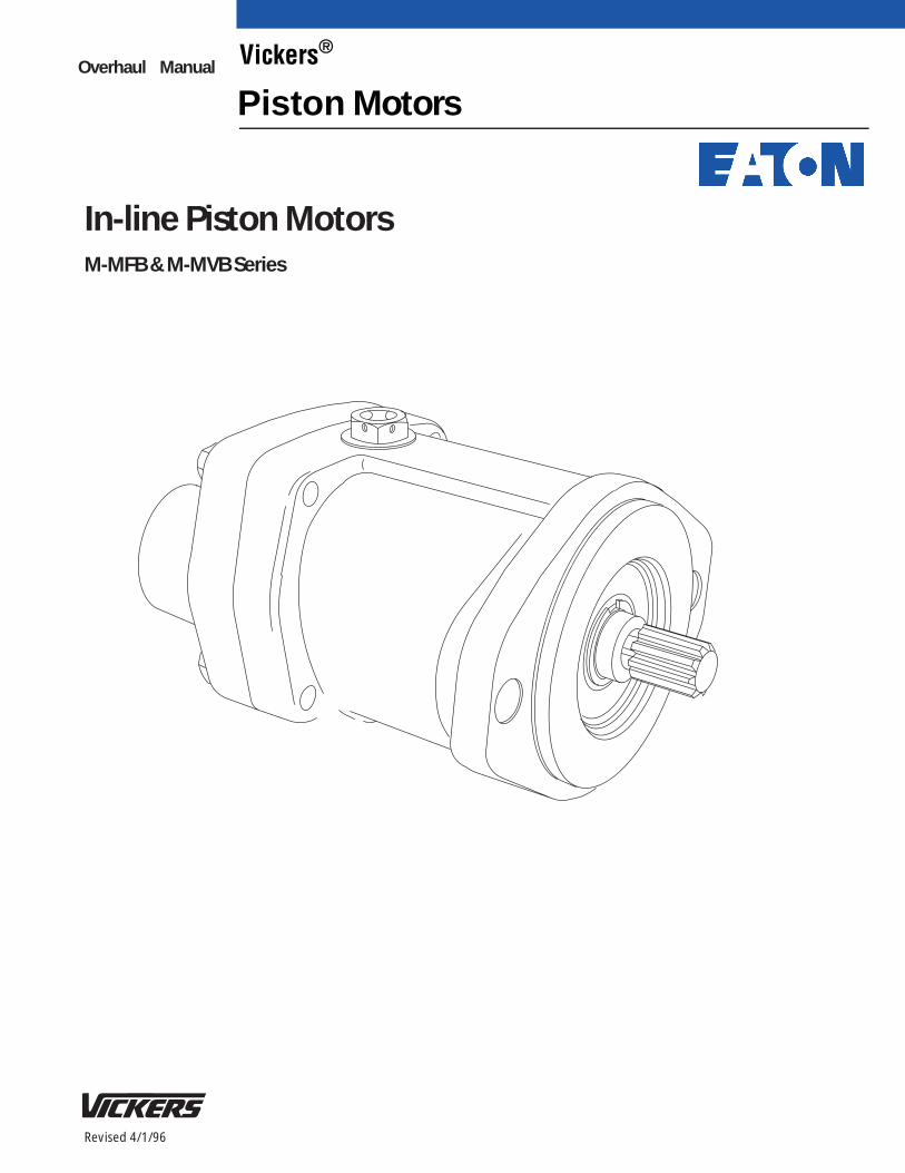
Revised 4/1/96 In-line Piston Motors M-MFB & M-MVB Series Overhaul Manual Vickers ® Piston Motors
Transcript of Vickers Overhaul Manual Piston Motors In-line Piston …pub/@eaton/@hyd/...3 Section I –...
Revised 4/1/96
In-line Piston MotorsM-MFB & M-MVB Series
Overhaul Manual Vickers®
Piston Motors
2
Table of Contents
Section Page
I. IntroductionA. Purpose of Manual 3. . . . . . . . . . . . . . . . . . . . . . . . . . . . . . . . . . . . . . . . . . . . . . . . . . . . . . . . . . . . . . . . . . . . . . . . . . . B. General Information 3. . . . . . . . . . . . . . . . . . . . . . . . . . . . . . . . . . . . . . . . . . . . . . . . . . . . . . . . . . . . . . . . . . . . . . . . . . .
II. DescriptionA. General 4. . . . . . . . . . . . . . . . . . . . . . . . . . . . . . . . . . . . . . . . . . . . . . . . . . . . . . . . . . . . . . . . . . . . . . . . . . . . . . . . . . . . . B. Assembly and Construction 4. . . . . . . . . . . . . . . . . . . . . . . . . . . . . . . . . . . . . . . . . . . . . . . . . . . . . . . . . . . . . . . . . . . . C. Application 4. . . . . . . . . . . . . . . . . . . . . . . . . . . . . . . . . . . . . . . . . . . . . . . . . . . . . . . . . . . . . . . . . . . . . . . . . . . . . . . . . .
III. Principles of OperationA. General 5. . . . . . . . . . . . . . . . . . . . . . . . . . . . . . . . . . . . . . . . . . . . . . . . . . . . . . . . . . . . . . . . . . . . . . . . . . . . . . . . . . . . . B. Fixed Displacement Pump 5. . . . . . . . . . . . . . . . . . . . . . . . . . . . . . . . . . . . . . . . . . . . . . . . . . . . . . . . . . . . . . . . . . . . . C. Variable Displacement Pump 5. . . . . . . . . . . . . . . . . . . . . . . . . . . . . . . . . . . . . . . . . . . . . . . . . . . . . . . . . . . . . . . . . . .
IV. Installation and Operation InstructionsA. Installation 6. . . . . . . . . . . . . . . . . . . . . . . . . . . . . . . . . . . . . . . . . . . . . . . . . . . . . . . . . . . . . . . . . . . . . . . . . . . . . . . . . . . B. Drive Connections 6. . . . . . . . . . . . . . . . . . . . . . . . . . . . . . . . . . . . . . . . . . . . . . . . . . . . . . . . . . . . . . . . . . . . . . . . . . . . C. Mounting 6. . . . . . . . . . . . . . . . . . . . . . . . . . . . . . . . . . . . . . . . . . . . . . . . . . . . . . . . . . . . . . . . . . . . . . . . . . . . . . . . . . . . D. Shaft Rotation 6. . . . . . . . . . . . . . . . . . . . . . . . . . . . . . . . . . . . . . . . . . . . . . . . . . . . . . . . . . . . . . . . . . . . . . . . . . . . . . . . E. Hydraulic Tubing 6. . . . . . . . . . . . . . . . . . . . . . . . . . . . . . . . . . . . . . . . . . . . . . . . . . . . . . . . . . . . . . . . . . . . . . . . . . . . . F. Hydraulic Fluid Recommendations 7. . . . . . . . . . . . . . . . . . . . . . . . . . . . . . . . . . . . . . . . . . . . . . . . . . . . . . . . . . . . . . G. Overload Protection 8. . . . . . . . . . . . . . . . . . . . . . . . . . . . . . . . . . . . . . . . . . . . . . . . . . . . . . . . . . . . . . . . . . . . . . . . . . . H. Starting and Priming 8. . . . . . . . . . . . . . . . . . . . . . . . . . . . . . . . . . . . . . . . . . . . . . . . . . . . . . . . . . . . . . . . . . . . . . . . . .
V. MaintenanceA. Service Tools 8. . . . . . . . . . . . . . . . . . . . . . . . . . . . . . . . . . . . . . . . . . . . . . . . . . . . . . . . . . . . . . . . . . . . . . . . . . . . . . . . B. Inspection and Service 8. . . . . . . . . . . . . . . . . . . . . . . . . . . . . . . . . . . . . . . . . . . . . . . . . . . . . . . . . . . . . . . . . . . . . . . . C. Adding Fluid to the System 9. . . . . . . . . . . . . . . . . . . . . . . . . . . . . . . . . . . . . . . . . . . . . . . . . . . . . . . . . . . . . . . . . . . . D. Lubrication 9. . . . . . . . . . . . . . . . . . . . . . . . . . . . . . . . . . . . . . . . . . . . . . . . . . . . . . . . . . . . . . . . . . . . . . . . . . . . . . . . . . E. Replacement Parts 9. . . . . . . . . . . . . . . . . . . . . . . . . . . . . . . . . . . . . . . . . . . . . . . . . . . . . . . . . . . . . . . . . . . . . . . . . . . F. Adjustments 9. . . . . . . . . . . . . . . . . . . . . . . . . . . . . . . . . . . . . . . . . . . . . . . . . . . . . . . . . . . . . . . . . . . . . . . . . . . . . . . . . G. Troubleshooting 9. . . . . . . . . . . . . . . . . . . . . . . . . . . . . . . . . . . . . . . . . . . . . . . . . . . . . . . . . . . . . . . . . . . . . . . . . . . . . .
VI. OverhaulA. General 10. . . . . . . . . . . . . . . . . . . . . . . . . . . . . . . . . . . . . . . . . . . . . . . . . . . . . . . . . . . . . . . . . . . . . . . . . . . . . . . . . . . . . B. Disassembly 11. . . . . . . . . . . . . . . . . . . . . . . . . . . . . . . . . . . . . . . . . . . . . . . . . . . . . . . . . . . . . . . . . . . . . . . . . . . . . . . . . C. Inspection and Repair 13. . . . . . . . . . . . . . . . . . . . . . . . . . . . . . . . . . . . . . . . . . . . . . . . . . . . . . . . . . . . . . . . . . . . . . . . . D. Assembly 14. . . . . . . . . . . . . . . . . . . . . . . . . . . . . . . . . . . . . . . . . . . . . . . . . . . . . . . . . . . . . . . . . . . . . . . . . . . . . . . . . . . .
VII. Testing 14. . . . . . . . . . . . . . . . . . . . . . . . . . . . . . . . . . . . . . . . . . . . . . . . . . . . . . . . . . . . . . . . . . . . . . . . . . . . . . . . . . . . . . . . . . . .
� Eaton Hydraulics, Incorporated 2000All Rights Reserved
3
Section I – Introduction
A. Purpose of ManualThe purpose of this manual is to describe the basicoperational characteristic and to provide service andoverhaul information for Vickers Fixed and Variable DeliveryIn-line Piston Motors. Models included in this series arelisted in Table 1. Information contained in this manualpertains to the latest designs. Earlier designs are coveredonly to the extent of their similarity to present equipment.
B. General InformationRelated Publications – Service parts information andinstallation dimensions are not contained in this manual. Theinstallation drawings and parts catalogs listed in Table 1 areavailable from Vickers.
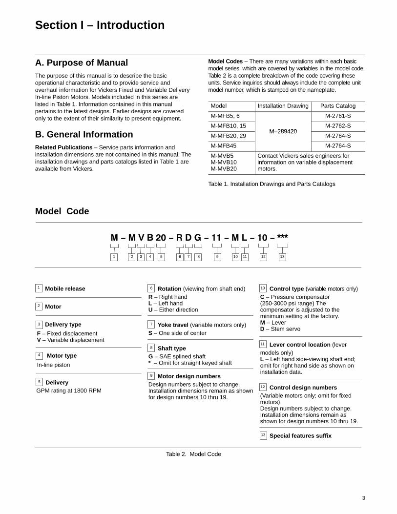
Model Codes – There are many variations within each basicmodel series, which are covered by variables in the model code.Table 2 is a complete breakdown of the code covering theseunits. Service inquiries should always include the complete unitmodel number, which is stamped on the nameplate.
Model Installation Drawing Parts Catalog
M-MFB5, 6 M-2761-S
M-MFB10, 15M 289420
M-2762-S
M-MFB20, 29M–289420
M-2764-S
M-MFB45 M-2764-S
M-MVB5M-MVB10M-MVB20
Contact Vickers sales engineers forinformation on variable displacementmotors.
Table 1. Installation Drawings and Parts Catalogs
Model Code
2
2 4 5 6 7 8 9 10 13111
Mobile release1
3 12
3
Motor
Delivery type
F – Fixed displacementV – Variable displacement
4
In-line piston
Motor type
5 DeliveryGPM rating at 1800 RPM
6 Rotation (viewing from shaft end)R – Right handL – Left handU – Either direction
10 Control type (variable motors only)C – Pressure compensator(250-3000 psi range) Thecompensator is adjusted to theminimum setting at the factory.M – LeverD – Stem servo
7 Yoke travel (variable motors only)S – One side of center
8 Shaft typeG – SAE splined shaft* – Omit for straight keyed shaft
9 Motor design numbersDesign numbers subject to change.Installation dimensions remain as shownfor design numbers 10 thru 19.
11 Lever control location (levermodels only)L – Left hand side-viewing shaft end;omit for right hand side as shown oninstallation data.
12 Control design numbers(Variable motors only; omit for fixedmotors)Design numbers subject to change.Installation dimensions remain asshown for design numbers 10 thru 19.
13 Special features suffix
Table 2. Model Code
4
Section II – Description
A. GeneralIn-line motors are of the axial piston, positive displacementtype and include both fixed and variable (adjustable)displacement motors capable of high pressure operation.Drive speeds vary with the model, type of fluid used andcircuit application.
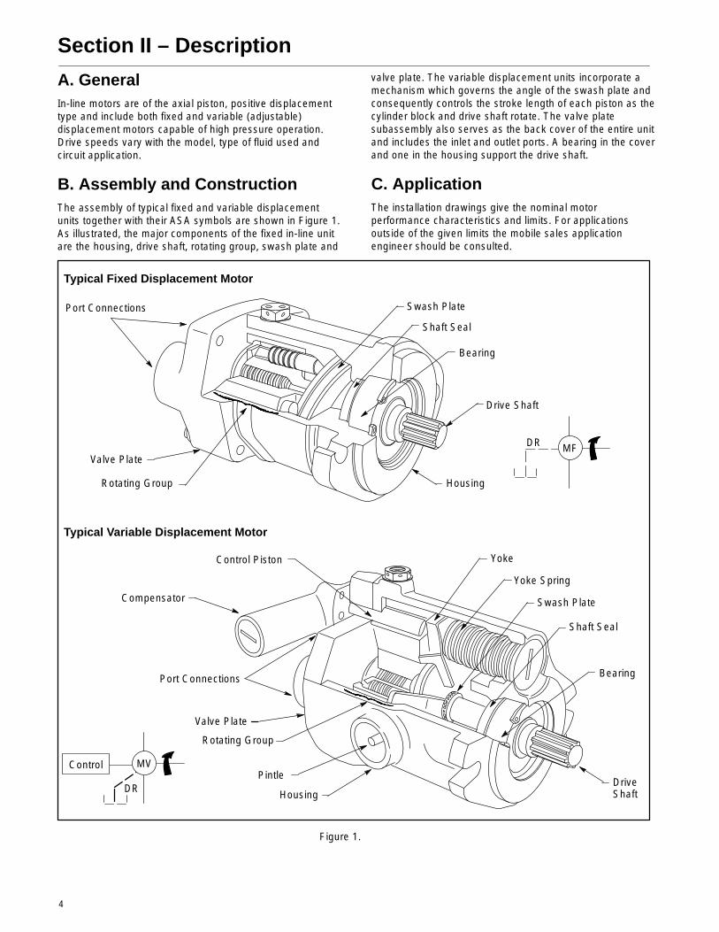
B. Assembly and ConstructionThe assembly of typical fixed and variable displacementunits together with their ASA symbols are shown in Figure 1.As illustrated, the major components of the fixed in-line unitare the housing, drive shaft, rotating group, swash plate and
valve plate. The variable displacement units incorporate amechanism which governs the angle of the swash plate andconsequently controls the stroke length of each piston as thecylinder block and drive shaft rotate. The valve platesubassembly also serves as the back cover of the entire unitand includes the inlet and outlet ports. A bearing in the coverand one in the housing support the drive shaft.
C. ApplicationThe installation drawings give the nominal motorperformance characteristics and limits. For applicationsoutside of the given limits the mobile sales applicationengineer should be consulted.
Figure 1.
Typical Fixed Displacement Motor
Typical Variable Displacement Motor
Port Connections
Valve Plate
Rotating Group
Swash Plate
Shaft Seal
Bearing
Drive Shaft
Housing
Port Connections
Compensator
Control Piston
Yoke Spring
DriveShaftHousing
Pintle
Rotating Group
Valve Plate
Bearing
Shaft Seal
Swash Plate
Yoke
MF
MVControl
DR
DR
5
Section III – Principles of Operation
A. GeneralAlthough nearly identical in design, pumps and motorsoperate essentially in reverse of each other; the pumpforcing fluid through the system as it rotates, the motor beingrotated by the fluid. Variable displacement units areconstructed so that the angle of displacement (angle of theswash plate to the drive shaft axis) can be varied bychanging the yoke position.
Motors are positive displacement units which are capable ofproducing a variable torque and speed. Motor speed is afunction of the input fluid volume. Torque is generated by thepressure drop across the motor. Maximum torque is limitedby system relief valve setting. On a variable displacementmotor, the angle of the swash plate affects the speed andtorque.
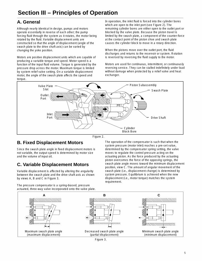
In operation, the inlet fluid is forced into the cylinder boreswhich are open to the inlet port (see Figure 2). Theremaining cylinder bores are either open to the outlet port orblocked by the valve plate. Because the piston travel islimited by the swash plate, a component of the counter-forceat the contact point of the piston shoe and swash platecauses the cylinder block to move in a rotary direction.
When the pistons move over the outlet port, the fluiddischarges and returns to the reservoir or system. Rotationis reversed by reversing the fluid supply to the motor.
Motors are used for continuous, intermittent, or continuouslyreversing service. They can be stalled indefinitely under loadwithout damage when protected by a relief valve and heatexchanger.
Figure 2.
Valve PlateSlot
OutletPort
InletPort
CylinderBlock Bore
Piston Subassembly
Swash Plate
Drive Shaft
B. Fixed Displacement MotorsSince the swash plate angle in fixed displacement motors isnot variable, the output speed is determined by motor sizeand the volume of input oil.
C. Variable Displacement MotorsVariable displacement is affected by altering the angularitybetween the swash plate and the drive shaft axis as shownby views A, B and C in Figure 3.
The pressure compensator is a spring-biased, pressureactuated, three-way valve incorporated onto the valve plate.
The operation of the compensator is such that when thesystem pressure (motor inlet) reaches a pre-set value,determined by the compensator spring setting, the valvemoves to regulate the control pressure acting on theactuating piston. As the force produced by the actuatingpiston overcomes the force of the opposing springs, theswash plate angle moves toward the minimum displacementposition, view C. The amount of angular movement of theswash plate (i.e., displacement change) is determined bysystem pressure. Equilibrium is achieved when the newdisplacement (i.e., motor torque) matches the systemrequirement.
Figure 3.
Maximum swash plate angle(maximum displacement)
Decreased swash plate angle(partial displacement)
Minimum swash plate angle(minimum displacement)
A B C
6
Section IV – Installation and Operating Instructions
A. InstallationInstallation drawings shown in Table 1 should be consultedfor installation information.
B. Drive Connections
CAUTION
Motor shafts are designed to be installed in flexiblecouplings with a slip fit or very light tap. Pounding caninjure the bearings. Shaft tolerances are shown onpump installation drawings. (See Table 1.)
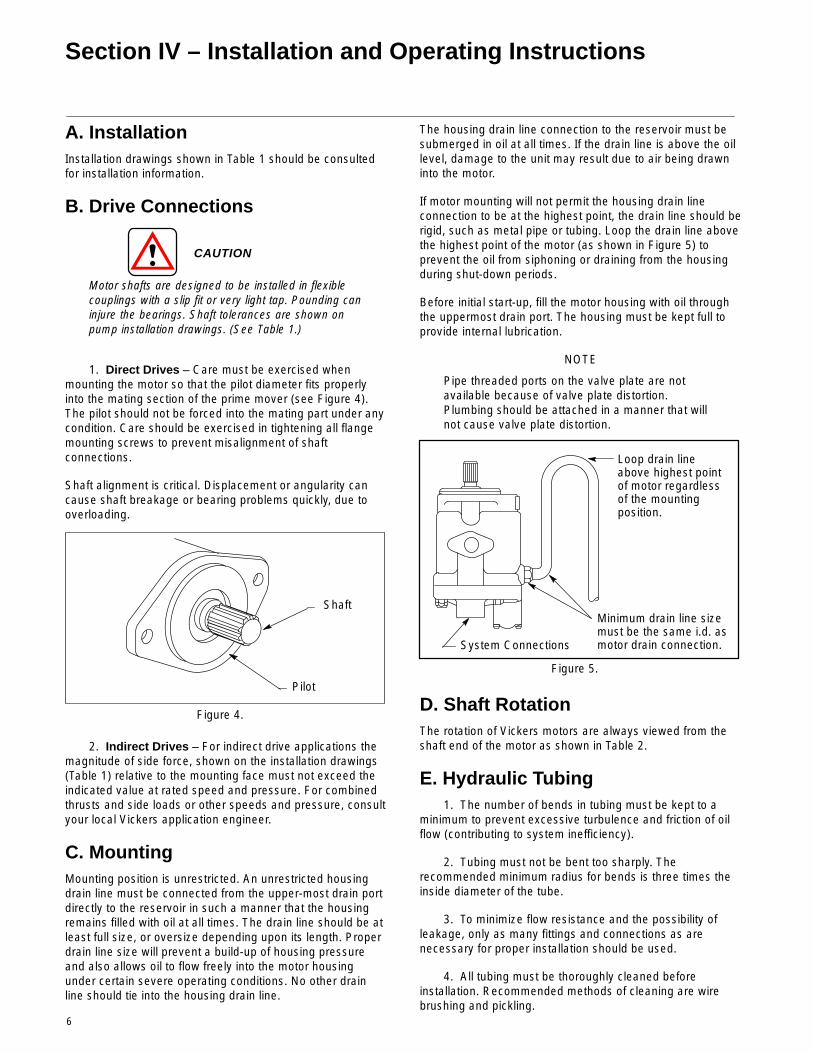
1. Direct Drives – Care must be exercised whenmounting the motor so that the pilot diameter fits properlyinto the mating section of the prime mover (see Figure 4).The pilot should not be forced into the mating part under anycondition. Care should be exercised in tightening all flangemounting screws to prevent misalignment of shaftconnections.
Shaft alignment is critical. Displacement or angularity cancause shaft breakage or bearing problems quickly, due tooverloading.
Figure 4.
Shaft
Pilot
2. Indirect Drives – For indirect drive applications themagnitude of side force, shown on the installation drawings(Table 1) relative to the mounting face must not exceed theindicated value at rated speed and pressure. For combinedthrusts and side loads or other speeds and pressure, consultyour local Vickers application engineer.
C. MountingMounting position is unrestricted. An unrestricted housingdrain line must be connected from the upper-most drain portdirectly to the reservoir in such a manner that the housingremains filled with oil at all times. The drain line should be atleast full size, or oversize depending upon its length. Properdrain line size will prevent a build-up of housing pressureand also allows oil to flow freely into the motor housingunder certain severe operating conditions. No other drainline should tie into the housing drain line.
The housing drain line connection to the reservoir must besubmerged in oil at all times. If the drain line is above the oillevel, damage to the unit may result due to air being drawninto the motor.
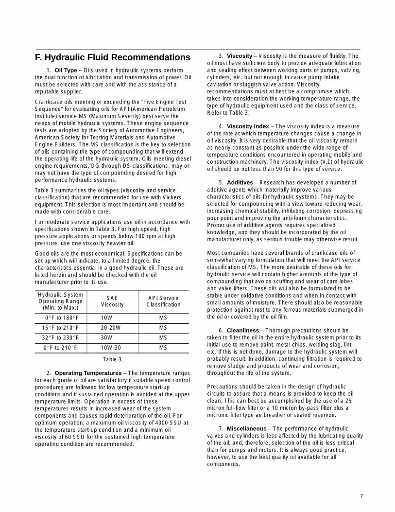
If motor mounting will not permit the housing drain lineconnection to be at the highest point, the drain line should berigid, such as metal pipe or tubing. Loop the drain line abovethe highest point of the motor (as shown in Figure 5) toprevent the oil from siphoning or draining from the housingduring shut-down periods.
Before initial start-up, fill the motor housing with oil throughthe uppermost drain port. The housing must be kept full toprovide internal lubrication.
NOTE
Pipe threaded ports on the valve plate are notavailable because of valve plate distortion.Plumbing should be attached in a manner that willnot cause valve plate distortion.
Figure 5.
Loop drain lineabove highest pointof motor regardlessof the mountingposition.
Minimum drain line sizemust be the same i.d. asmotor drain connection.System Connections
D. Shaft RotationThe rotation of Vickers motors are always viewed from theshaft end of the motor as shown in Table 2.
E. Hydraulic Tubing1. The number of bends in tubing must be kept to a
minimum to prevent excessive turbulence and friction of oilflow (contributing to system inefficiency).
2. Tubing must not be bent too sharply. Therecommended minimum radius for bends is three times theinside diameter of the tube.
3. To minimize flow resistance and the possibility ofleakage, only as many fittings and connections as arenecessary for proper installation should be used.
4. All tubing must be thoroughly cleaned beforeinstallation. Recommended methods of cleaning are wirebrushing and pickling.
7
F. Hydraulic Fluid Recommendations1. Oil Type – Oils used in hydraulic systems perform
the dual function of lubrication and transmission of power. Oilmust be selected with care and with the assistance of areputable supplier.
Crankcase oils meeting or exceeding the “Five Engine TestSequence” for evaluating oils for API (American PetroleumInstitute) service MS (Maximum Severity) best serve theneeds of mobile hydraulic systems. These engine sequencetests are adopted by the Society of Automotive Engineers,American Society for Testing Materials and AutomotiveEngine Builders. The MS classification is the key to selectionof oils containing the type of compounding that will extendthe operating life of the hydraulic system. Oils meeting dieselengine requirements, DG through DS classifications, may ormay not have the type of compounding desired for highperformance hydraulic systems.
Table 3 summarizes the oil types (viscosity and serviceclassification) that are recommended for use with Vickersequipment. This selection is most important and should bemade with considerable care.
For moderate service applications use oil in accordance withspecifications shown in Table 3. For high speed, highpressure applications or speeds below 100 rpm at highpressure, use one viscosity heavier oil.
Good oils are the most economical. Specifications can beset up which will indicate, to a limited degree, thecharacteristics essential in a good hydraulic oil. These arelisted herein and should be checked with the oilmanufacturer prior to its use.
Hydraulic SystemOperating Range
(Min. to Max.)
SAEViscosity
API ServiceClassification
0�F to 180�F 10W MS
15�F to 210�F 20-20W MS
32�F to 230�F 30W MS
0�F to 210�F 10W-30 MS
Table 3.
2. Operating Temperatures – The temperature rangesfor each grade of oil are satisfactory if suitable speed controlprocedures are followed for low temperature start-upconditions and if sustained operation is avoided at the uppertemperature limits. Operation in excess of thesetemperatures results in increased wear of the systemcomponents and causes rapid deterioration of the oil. Foroptimum operation, a maximum oil viscosity of 4000 SSU atthe temperature start-up condition and a minimum oilviscosity of 60 SSU for the sustained high temperatureoperating condition are recommended.
3. Viscosity – Viscosity is the measure of fluidity. Theoil must have sufficient body to provide adequate lubricationand sealing effect between working parts of pumps, valving,cylinders, etc. but not enough to cause pump intakecavitation or sluggish valve action. Viscosityrecommendations must at best be a compromise whichtakes into consideration the working temperature range, thetype of hydraulic equipment used and the class of service.Refer to Table 3.
4. Viscosity Index – The viscosity index is a measureof the rate at which temperature changes cause a change inoil viscosity. It is very desirable that the oil viscosity remainas nearly constant as possible under the wide range oftemperature conditions encountered in operating mobile andconstruction machinery. The viscosity index (V.I.) of hydraulicoil should be not less than 90 for this type of service.
5. Additives – Research has developed a number ofadditive agents which materially improve variouscharacteristics of oils for hydraulic systems. They may beselected for compounding with a view toward reducing wear,increasing chemical stability, inhibiting corrosion, depressingpour point and improving the anti-foam characteristics.Proper use of additive agents requires specializedknowledge, and they should be incorporated by the oilmanufacturer only, as serious trouble may otherwise result.
Most companies have several brands of crankcase oils ofsomewhat varying formulation that will meet the API serviceclassification of MS. The more desirable of these oils forhydraulic service will contain higher amounts of the type ofcompounding that avoids scuffing and wear of cam lobesand valve lifters. These oils will also be formulated to bestable under oxidative conditions and when in contact withsmall amounts of moisture. There should also be reasonableprotection against rust to any ferrous materials submerged inthe oil or covered by the oil film.
6. Cleanliness – Thorough precautions should betaken to filter the oil in the entire hydraulic system prior to itsinitial use to remove paint, metal chips, welding slag, lint,etc. If this is not done, damage to the hydraulic system willprobably result. In addition, continuing filtration is required toremove sludge and products of wear and corrosion,throughout the life of the system.
Precautions should be taken in the design of hydrauliccircuits to assure that a means is provided to keep the oilclean. This can best be accomplished by the use of a 25micron full-flow filter or a 10 micron by-pass filter plus amicronic filter type air breather or sealed reservoir.
7. Miscellaneous – The performance of hydraulicvalves and cylinders is less affected by the lubricating qualityof the oil, and, therefore, selection of the oil is less criticalthan for pumps and motors. It is always good practice,however, to use the best quality oil available for allcomponents.
8
G. Overload ProtectionA relief valve must be installed in the system to protectcomponents from excessive pressure. The setting of therelief valve depends on the work requirements of the systemand the maximum pressure ratings of system components.
NOTE
Do not allow system pressure to exceed motorrating due to valving configurations.
H. Starting and PrimingNOTE
In most cases “break in” is not a problem but whenit is, it can be compared with new engines, gearboxes and other products. A by-product of “breakin” is self generated dirt. Generous filters and goodfilter maintenance are required to be sure a unit is“broken in” and not “broken up”.
1. Precautions
a. Make sure the reservoir air cleaner is clean andof ample size to handle the system breathing requirements.
b. Make certain the hydraulic system is clean andfree of dirt, metal chips, paint, welding slag and foreignmaterial. System filtration should be 25 microns or finer.
c. Make sure all inlet and system return line fittingsare tight so that air is not drawn into the system.
d. Make sure the system is full of oil. Most of the MScrankcase oils will serve the needs of inline motorapplications (refer to fluid recommendations in Section IV, H).
e. Make sure shaft rotation direction and couplingalignment are correct.
CAUTION
Be absolutely sure the housing is full of oil beforestarting. Fill the housing with system fluid throughthe uppermost drain port.
f. Bleed the motor outlet line until a clear stream ofoil results with no air bubbles present. This is bestaccomplished by loosening an inlet fitting next to the motor.Slowly extend and retract all hydraulic cylinders in the circuitand again bleed the inlet line. It may be necessary to bleedthe circuit several times in order to remove all the air trappedin the circuit.
If the air is not expelled from the circuit after severalattempts, check the inlet lines to the motor to make sure allthe fittings are tight. When a hose is used for the inlet line forthe pump, it is not uncommon for it to leak where it isattached to the fitting and allow air to be drawn into thesystem.
g. Allow the unit to run at minimum operating speedfor as long as possible while checking the system for leaksand bleeding air out of the lines. Do not remove thecompensator adjustment plug while the motor is in operation.
Section V – Service, Inspection and Maintenance
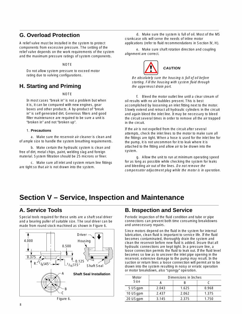
A. Service ToolsSpecial tools required for these units are a shaft seal driverand a bearing puller of suitable size. The seal driver can bemade from round stock machined as shown in Figure 6.
Figure 6.
A
BC
4.000
0.375
R.
0.500
0.1251/8545� 1/16515� Shaft Seal
Housing
Driver
Shaft Seal Installation
B. Inspection and ServicePeriodic inspection of the fluid condition and tube or pipeconnections can prevent both time consuming breakdownsand unnecessary repairs.
Since motors depend on the fluid in the system for internallubrication, clean fluid is important to service life. If the fluidbecomes contaminated, thoroughly drain the system andclean the reservoir before new fluid is added. Insure that allhydraulic connections are kept tight. In a pressure line, aloose connection permits the fluid to leak out. If the fluid levelbecomes so low as to uncover the inlet pipe opening in thereservoir, extensive damage to the pump may result. In thesuction or return lines a loose connection will permit air to bedrawn into the system resulting in noisy or erratic operationor motor breakdown, also “spongy” operation.
Motori
Dimensions in InchesSize A B C
5 USgpm 2.043 1.625 0.96810 USgpm 2.437 2.062 1.37520 USgpm 3.145 2.375 1.750
9
Check and replace filter elements periodically. A cloggedfilter element results in a higher pressure drop, forcingparticles through the filter which would ordinarily be trapped,or causing the by-pass to open resulting in a partial orcomplete loss of filtration.
C. Adding Fluid to the SystemWhen hydraulic fluid is added to replenish the system, itshould always be poured through a micron filter. If such afilter is not available, a funnel with a fine wire screen (200mesh or better) can be used.
It is important that oil be clean and free of all substancewhich will cause improper operation and excessive wear ofany unit in the system.
D. LubricationInternal lubrication is provided by system oil flow, exceptmain bearing which must be packed 1/3 full of hightemperature grease when unit is rebuilt.
E. Replacement PartsOnly genuine parts manufactured or sold by Vickers,Incorporated should be used as replacement parts forthese motors. They are shown in the parts catalogslisted in Table 1. Copies are available on request.
F. AdjustmentsNo periodic adjustments are required, other than tomaintain proper shaft alignment with the driving medium.
G. TroubleshootingThe cause of improper functioning in a hydraulic system isbest diagnosed with the use of proper and adequate testingequipment and a thorough understanding of the completehydraulic system.
A hydraulic motor exhibiting an excessive increase in heat ornoise is a potential failure. When either of these conditionsare noticed, immediately shut down the machine, locate thetrouble and correct it.
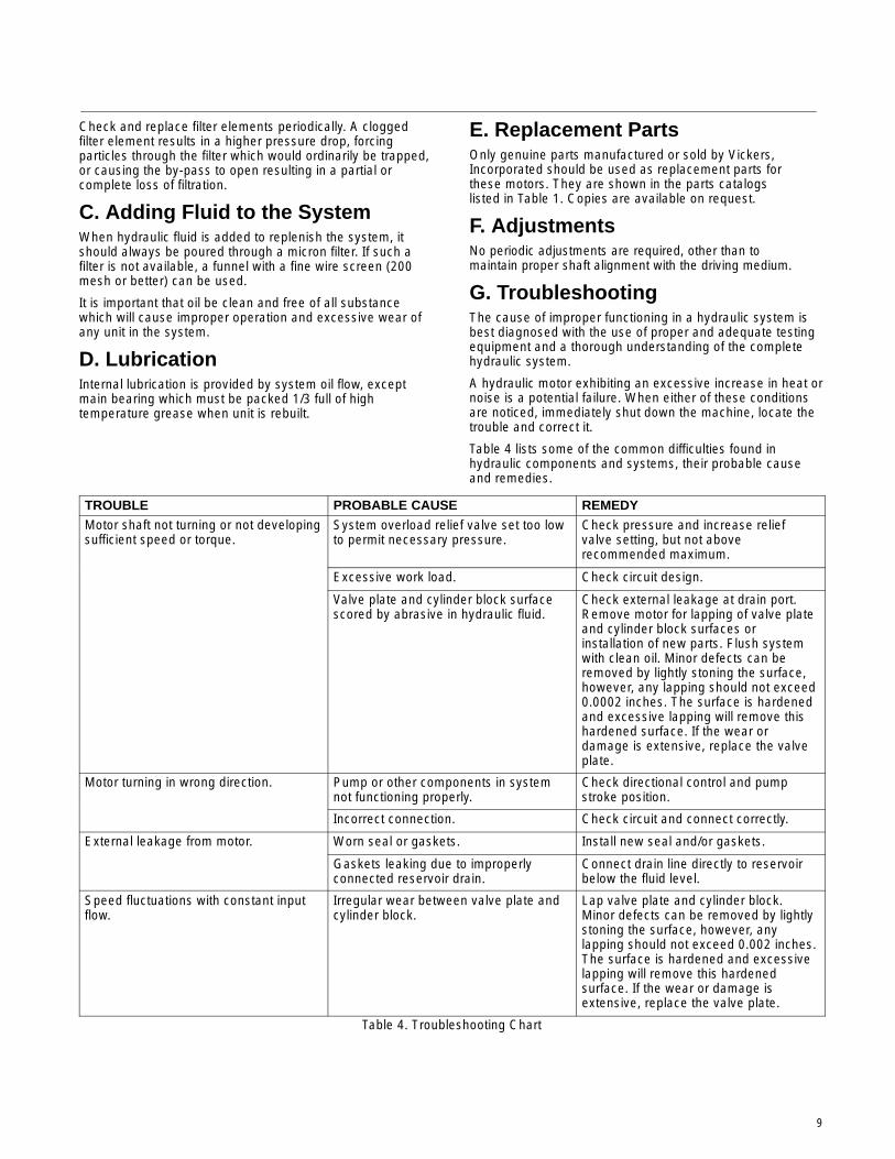
Table 4 lists some of the common difficulties found inhydraulic components and systems, their probable causeand remedies.
TROUBLE PROBABLE CAUSE REMEDY
Motor shaft not turning or not developingsufficient speed or torque.
System overload relief valve set too lowto permit necessary pressure.
Check pressure and increase reliefvalve setting, but not aboverecommended maximum.
Excessive work load. Check circuit design.
Valve plate and cylinder block surfacescored by abrasive in hydraulic fluid.
Check external leakage at drain port.Remove motor for lapping of valve plateand cylinder block surfaces orinstallation of new parts. Flush systemwith clean oil. Minor defects can beremoved by lightly stoning the surface,however, any lapping should not exceed0.0002 inches. The surface is hardenedand excessive lapping will remove thishardened surface. If the wear ordamage is extensive, replace the valveplate.
Motor turning in wrong direction. Pump or other components in systemnot functioning properly.
Check directional control and pumpstroke position.
Incorrect connection. Check circuit and connect correctly.
External leakage from motor. Worn seal or gaskets. Install new seal and/or gaskets.
Gaskets leaking due to improperlyconnected reservoir drain.
Connect drain line directly to reservoirbelow the fluid level.
Speed fluctuations with constant inputflow.
Irregular wear between valve plate andcylinder block.
Lap valve plate and cylinder block.Minor defects can be removed by lightlystoning the surface, however, anylapping should not exceed 0.002 inches.The surface is hardened and excessivelapping will remove this hardenedsurface. If the wear or damage isextensive, replace the valve plate.
Table 4. Troubleshooting Chart
10
Section VI – Overhaul
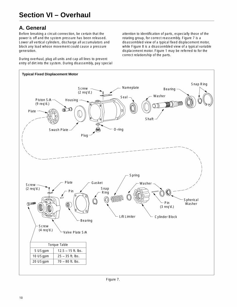
A. GeneralBefore breaking a circuit connection, be certain that thepower is off and the system pressure has been released.Lower all vertical cylinders, discharge all accumulators andblock any load whose movement could cause a pressuregeneration.
During overhaul, plug all units and cap all lines to prevententry of dirt into the system. During disassembly, pay special
attention to identification of parts, especially those of therotating group, for correct reassembly. Figure 7 is adisassembled view of a typical fixed displacement motor,while Figure 8 is a disassembled view of a typical variabledisplacement motor. Figure 1 may be referred to for thecorrect relationship of the parts.
Figure 7.
Torque Table
5 USgpm 12.5 – 15 ft. lbs.
10 USgpm 25 – 35 ft. lbs.
20 USgpm 70 – 80 ft. lbs.
Plate
Piston S/A(9 req’d.)
Housing
Screw(2 req’d.)
Nameplate
Seal Washer
BearingSnap Ring
Swash Plate
Plug
O-ring
Shaft
Screw(2 req’d.)
Plate
Pin
Bearing
Gasket
Snap Ring
Spring
Washer
Screw(4 req’d.)
Valve Plate S/A
Lift Limiter Cylinder Block
Pin(3 req’d.)
SphericalWasher
Typical Fixed Displacement Motor
11
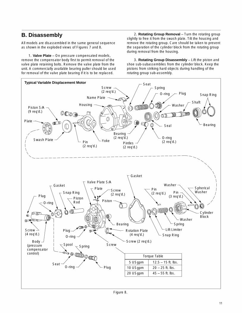
B. DisassemblyAll models are disassembled in the same general sequenceas shown in the exploded views of Figures 7 and 8.
1. Valve Plate – On pressure compensated models,remove the compensator body first to permit removal of thevalve plate retaining bolts. Remove the valve plate from theunit. A commercially available bearing puller should be usedfor removal of the valve plate bearing if it is to be replaced.
2. Rotating Group Removal – Turn the rotating groupslightly to free it from the swash plate. Tilt the housing andremove the rotating group. Care should be taken to preventthe separation of the cylinder block from the rotating groupduring removal from the housing.
3. Rotating Group Disassembly – Lift the piston andshoe sub-subassemblies from the cylinder block. Keep thepistons from striking hard objects during handling of therotating group sub-assembly.
Figure 8.
Torque Table
5 USgpm 12.5 – 15 ft. lbs.
10 USgpm 20 – 25 ft. lbs.
20 USgpm 45 – 55 ft. lbs.
Plate
Piston S/A(9 req’d.)
Swash PlatePin(2 req’d.)
Yoke
Housing
Name Plate
Bearing(2 req’d.)
Screw(2 req’d.)
SeatSpring
Plug
Shaft
Pintles(2 req’d.)
O-ring(2 req’d.)
Seal Bearing
Snap Ring
Screw(4 req’d.)
PlugSnap Ring
PistonRod
Valve Plate S/A
Piston
Screw(2 req’d.)
PlateGasket
Pin(2 req’d.) Pin
(3 req’d.)
SphericalWasher
Washer
Body(pressurecompensatorcontrol)
Seat
Spring
Plug
Typical Variable Displacement Motor
Washer
O-ring
O-ring
O-ring
Gasket
Spool
Plug
O-ring
Bearing
Screw
Rotation Plate(4 req’d.)
Screw (2 req’d.)
Lift Limiter
Washer
CylinderBlock
Spring
Snap Ring
12
WARNING
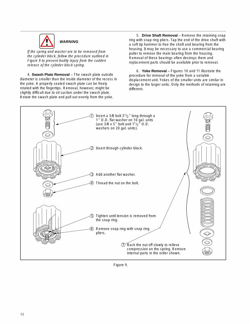
If the spring and washer are to be removed fromthe cylinder block, follow the procedure outlined inFigure 9 to prevent bodily injury from the suddenrelease of the cylinder block spring.
4. Swash Plate Removal – The swash plate outsidediameter is smaller than the inside diameter of the recess inthe yoke. A properly seated swash plate can be freelyrotated with the fingertips. Removal, however, might beslightly difficult due to oil suction under the swash plate.Rotate the swash plate and pull out evenly from the yoke.
5. Drive Shaft Removal – Remove the retaining snapring with snap ring pliers. Tap the end of the drive shaft witha soft tip hammer to free the shaft and bearing from thehousing. It may be necessary to use a commercial bearingpuller to remove the main bearing from the housing.Removal of these bearings often destroys them andreplacement parts should be available prior to removal.
6. Yoke Removal – Figures 10 and 11 illustrate theprocedure for removal of the yoke from a variabledisplacement unit. Yokes of the smaller units are similar indesign to the larger units. Only the methods of retaining aredifferent.
Figure 9.
1 Insert a 3/8 bolt 31/2� long through a1� O.D. flat washer on 10 gal. units(use 3/8 x 5� bolt and 11/2� O.D.washers on 20 gal. units).
2 Insert through cylinder block.
3 Add another flat washer.
4 Thread the nut on the bolt.
5 Tighten until tension is removed fromthe snap ring.
6 Remove snap ring with snap ringpliers.
7 Back the nut off slowly to relievecompression on the spring. Removeinternal parts in the order shown.
13
Figure 10.
Figure 11.
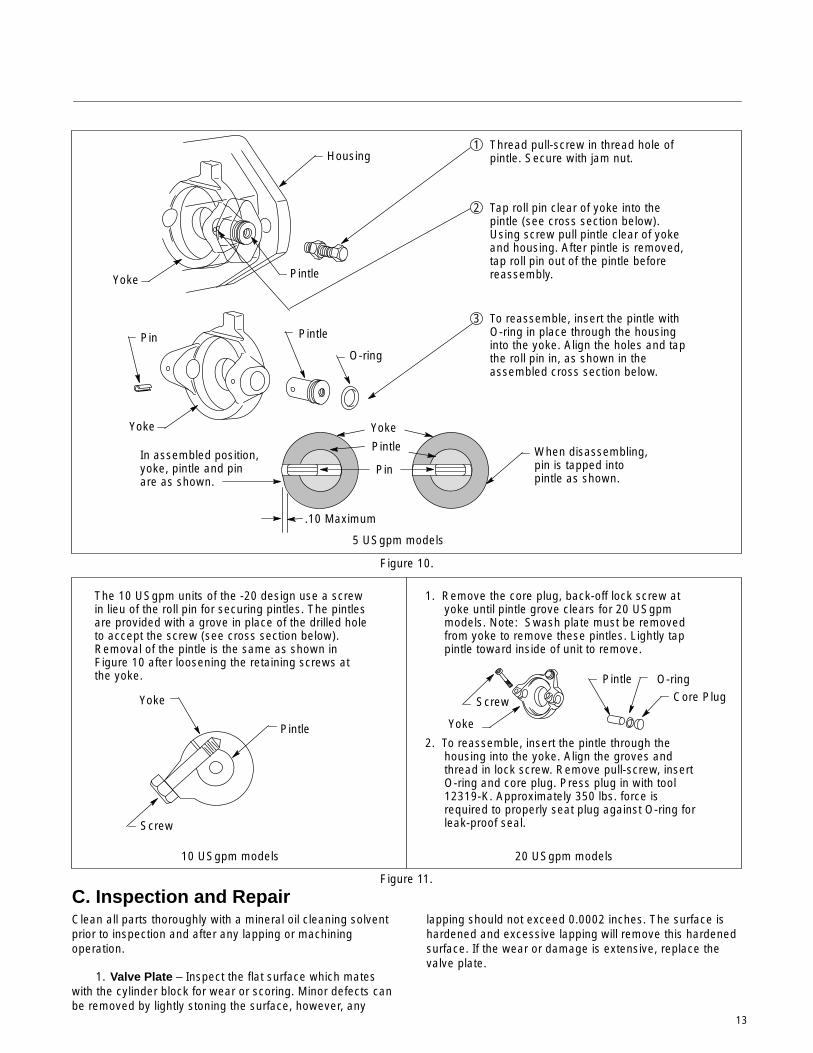
1 Thread pull-screw in thread hole ofpintle. Secure with jam nut.
2 Tap roll pin clear of yoke into thepintle (see cross section below).Using screw pull pintle clear of yokeand housing. After pintle is removed,tap roll pin out of the pintle beforereassembly.
3 To reassemble, insert the pintle withO-ring in place through the housinginto the yoke. Align the holes and tapthe roll pin in, as shown in theassembled cross section below.
In assembled position,yoke, pintle and pinare as shown.
When disassembling,pin is tapped intopintle as shown.
5 USgpm models
The 10 USgpm units of the -20 design use a screwin lieu of the roll pin for securing pintles. The pintlesare provided with a grove in place of the drilled holeto accept the screw (see cross section below).Removal of the pintle is the same as shown inFigure 10 after loosening the retaining screws atthe yoke.
1. Remove the core plug, back-off lock screw atyoke until pintle grove clears for 20 USgpmmodels. Note: Swash plate must be removedfrom yoke to remove these pintles. Lightly tappintle toward inside of unit to remove.
2. To reassemble, insert the pintle through thehousing into the yoke. Align the groves andthread in lock screw. Remove pull-screw, insertO-ring and core plug. Press plug in with tool12319-K. Approximately 350 lbs. force isrequired to properly seat plug against O-ring forleak-proof seal.
10 USgpm models 20 USgpm models
Housing
Yoke Pintle
Pin Pintle
O-ring
.10 Maximum
Pintle
Yoke
Screw
Yoke
Pintle O-ringCore PlugScrew
Pin
Yoke
Pintle
Yoke
C. Inspection and RepairClean all parts thoroughly with a mineral oil cleaning solventprior to inspection and after any lapping or machiningoperation.
1. Valve Plate – Inspect the flat surface which mateswith the cylinder block for wear or scoring. Minor defects canbe removed by lightly stoning the surface, however, any
lapping should not exceed 0.0002 inches. The surface ishardened and excessive lapping will remove this hardenedsurface. If the wear or damage is extensive, replace thevalve plate.
14
2. Rotating Group – Inspect the bores and valve platemating surface of the cylinder block for wear and scoring.Minor defects on valve plate mating face can be removed bylightly stoning the surface. If the defects cannot be removedby this method, the cylinder block should be replaced.
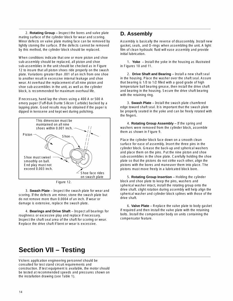
When conditions indicate that one or more piston and shoesub-assembly should be replaced, all piston and shoesub-assemblies in the unit should be checked as in Figure12 to insure that all piston shoes ride properly on the swashplate. Variations greater than .001 of an inch from one shoeto another result in excessive internal leakage and shoewear. At overhaul the replacement of all nine piston andshoe sub-assemblies in the unit, as well as the cylinderblock, is recommended for maximum overhaul life.
If necessary, hand lap the shoes using a 400 A or 500 Aemery paper (Tuff-Bak Durite Silicon Carbide) backed by alapping plate. Good results may be obtained if the paper isdipped in kerosene and kept wet during polishing.
Figure 12.
Shoe must swivelsmoothly on ball.End play must notexceed 0.003 inch.
This dimension must bemaintained on all nineshoes within 0.001 inch.
Piston Shoe
Shoe face rideson swash plate
3. Swash Plate – Inspect the swash plate for wear andscoring. If the defects are minor, stone the swash plate butdo not remove more than 0.0004 of an inch. If wear ordamage is extensive, replace the swash plate.
4. Bearings and Drive Shaft – Inspect all bearings forroughness or excessive play and replace if necessary.Inspect the shaft seal area of the shaft for scoring or wear.Replace the drive shaft if bent or wear is excessive.
D. AssemblyAssembly is basically the reverse of disassembly. Install newgasket, seals, and O-rings when assembling the unit. A lightfilm of clean hydraulic fluid will ease assembly and provideinitial lubrication.
1. Yoke – Install the yoke in the housing as illustratedin Figures 10 and 11.
2. Drive Shaft and Bearing – Install a new shaft sealin the housing. Place the washer over the shaft seal. Assurethat bearing is 1/3 to 1/2 filled with a good grade of hightemperature ball bearing grease, then install the drive shaftand bearing in the housing. Secure the drive shaft bearingwith the retaining ring.
3. Swash Plate – Install the swash plate chamferededge toward shaft seal. It is important that the swash platebe properly seated in the yoke and can be freely rotated withthe fingers.
4. Rotating Group Assembly – If the spring andwashers were removed from the cylinder block, assemblethem as shown in Figure 9.
Place the cylinder block face down on a smooth cleansurface for ease of assembly. Insert the three pins in thecylinder block. Grease the back-up and spherical washersand place them on the pins. Put the nine piston and shoesub-assemblies in the shoe plate. Carefully holding the shoeplate so that the pistons do not strike each other, align thepistons with the bores and maneuver them into place. Thepistons must move freely in a lubricated block bore.
5. Rotating Group Insertion – Holding the cylinderblock and shoe plate to keep the pins, washers andspherical washer intact, install the rotating group onto thedrive shaft. slight rotation during assembly will help align thespherical washer and cylinder block splines with those of thedrive shaft.
6. Valve Plate – Replace the valve plate to body gasketif required and then install the valve plate with the retainingbolts. Install the compensator body on units containing thecompensator feature.
Section VII – TestingVickers application engineering personnel should beconsulted for test stand circuit requirements andconstruction. If test equipment is available, the motor shouldbe tested at recommended speeds and pressures shown onthe installation drawing (see Table 1).

© 2008 Eaton CorporationAll Rights ReservedPrinted in USADocument No. V-MOPI-TM001-ESupersedes M-2760-SJanuary 2009
EatonFluid Power GroupHydraulics Business USA14615 Lone Oak RoadEden Prairie, MN 55344USATel: 952-937-9800Fax: 952-294-7722www.eaton.com/hydraulics
EatonFluid Power GroupHydraulics Business EuropeRoute de la Longeraie 71110 MorgesSwitzerlandTel: +41 (0) 21 811 4600Fax: +41 (0) 21 811 4601
EatonFluid Power GroupHydraulics Business Asia Pacific 11th Floor Hong Kong New World Tower 300 Huaihai Zhong Road Shanghai 200021 China Tel: 86-21-6387-9988 Fax: 86-21-6335-3912