
Vickers Hardness Measurements of the M855 Cartridge ... Hardness Testing .....3 3. Experimental...
26
Vickers Hardness Measurements of the M855 Cartridge Case Base by Joseph South, Franklin Kellogg, and Dennis Henry ARL-TR-4781 April 2009 Approved for public release; distribution is unlimited.
Transcript of Vickers Hardness Measurements of the M855 Cartridge ... Hardness Testing .....3 3. Experimental...
Vickers Hardness Measurements of the M855
Cartridge Case Base
by Joseph South, Franklin Kellogg, and Dennis Henry
ARL-TR-4781 April 2009
Approved for public release; distribution is unlimited.

NOTICES
Disclaimers The findings in this report are not to be construed as an official Department of the Army position unless so designated by other authorized documents. Citation of manufacturer’s or trade names does not constitute an official endorsement or approval of the use thereof. Destroy this report when it is no longer needed. Do not return it to the originator.
Army Research Laboratory Aberdeen Proving Ground, MD 21005-5069
ARL-TR-4781 April 2009
Vickers Hardness Measurements of the M855 Cartridge Case Base
Joseph South, Franklin Kellogg, and Dennis Henry
Weapons and Materials Research Directorate, ARL Approved for public release; distribution is unlimited.
ii
REPORT DOCUMENTATION PAGE Form Approved OMB No. 0704-0188
Public reporting burden for this collection of information is estimated to average 1 hour per response, including the time for reviewing instructions, searching existing data sources, gathering and maintaining the data needed, and completing and reviewing the collection information. Send comments regarding this burden estimate or any other aspect of this collection of information, including suggestions for reducing the burden, to Department of Defense, Washington Headquarters Services, Directorate for Information Operations and Reports (0704-0188), 1215 Jefferson Davis Highway, Suite 1204, Arlington, VA 22202-4302. Respondents should be aware that notwithstanding any other provision of law, no person shall be subject to any penalty for failing to comply with a collection of information if it does not display a currently valid OMB control number. PLEASE DO NOT RETURN YOUR FORM TO THE ABOVE ADDRESS.
1. REPORT DATE (DD-MM-YYYY)
April 2009 2. REPORT TYPE
Final 3. DATES COVERED (From - To)
April 2008–September 2008 4. TITLE AND SUBTITLE
Vickers Hardness Measurements of the M855 Cartridge Case Base 5a. CONTRACT NUMBER
5b. GRANT NUMBER
5c. PROGRAM ELEMENT NUMBER
6. AUTHOR(S)
Joseph South, Franklin Kellogg, and Dennis Henry 5d. PROJECT NUMBER
622618AH80 5e. TASK NUMBER
5f. WORK UNIT NUMBER
7. PERFORMING ORGANIZATION NAME(S) AND ADDRESS(ES)
U.S. Army Research Laboratory ATTN: AMSRD-ARL-WM-MB Aberdeen Proving Ground, MD 21005-5069
8. PERFORMING ORGANIZATION REPORT NUMBER
ARL-TR-4781
9. SPONSORING/MONITORING AGENCY NAME(S) AND ADDRESS(ES)
Program Manager - Maneuver Ammunition Systems SFAE AMO MAS MC Bldg. 354 Picatinny Arsenal, NJ 07806-5000
10. SPONSOR/MONITOR’S ACRONYM(S)
PM-MAS
11. SPONSOR/MONITOR'S REPORT NUMBER(S)
12. DISTRIBUTION/AVAILABILITY STATEMENT
Approved for public release; distribution is unlimited.
13. SUPPLEMENTARY NOTES
14. ABSTRACT
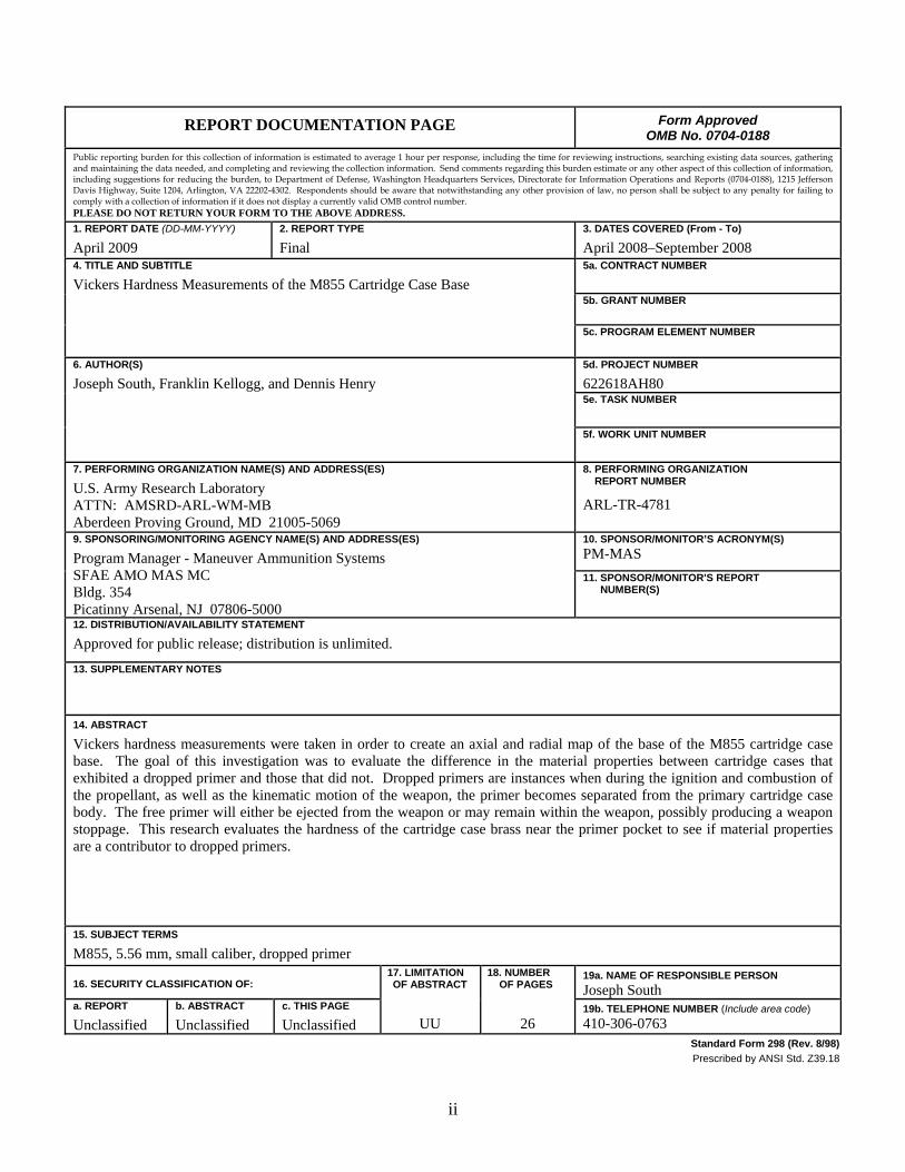
Vickers hardness measurements were taken in order to create an axial and radial map of the base of the M855 cartridge case base. The goal of this investigation was to evaluate the difference in the material properties between cartridge cases that exhibited a dropped primer and those that did not. Dropped primers are instances when during the ignition and combustion of the propellant, as well as the kinematic motion of the weapon, the primer becomes separated from the primary cartridge case body. The free primer will either be ejected from the weapon or may remain within the weapon, possibly producing a weapon stoppage. This research evaluates the hardness of the cartridge case brass near the primer pocket to see if material properties are a contributor to dropped primers.
15. SUBJECT TERMS
M855, 5.56 mm, small caliber, dropped primer
16. SECURITY CLASSIFICATION OF: 17. LIMITATION OF ABSTRACT
UU
18. NUMBER OF PAGES
26
19a. NAME OF RESPONSIBLE PERSON
Joseph South a. REPORT
Unclassified b. ABSTRACT
Unclassified c. THIS PAGE
Unclassified 19b. TELEPHONE NUMBER (Include area code)
410-306-0763 Standard Form 298 (Rev. 8/98)
Prescribed by ANSI Std. Z39.18

iii
Contents
List of Figures iv
List of Tables iv
Acknowledgments v
1. Introduction 1
2. Experimental 3
2.1 Aliant Techsystems Inc. Samples ....................................................................................3
2.2 ARDEC Samples .............................................................................................................3
2.3 Hardness Testing .............................................................................................................3
3. Experimental Results for Hardness Testing 4
4. Discussion 8
5. Conclusions 8
Appendix. Hardness Testing Data 11
Distribution List 15
iv
List of Figures
Figure 1. The M855 cartridge case and the associated hardness gradient (the primer and propellant are not shown)...........................................................................................................1
Figure 2. Picture of the A–D hardness locations at the head of the M855 cartridge case (dimensional units are in inches). ..............................................................................................2
Figure 3. Cross section of a base of a M855 cartridge showing the common origin axes. ............4
Figure 4. Picture of the 3 × 7 hardness testing array. .....................................................................5
Figure 5. Plot of the hardness results for the 0.4-mm radial location. ............................................5
Figure 6. Plot of the hardness results for the 0.8-mm radial location. ............................................6
Figure 7. Plot of the hardness results for the 1.2-mm radial location. ............................................6
Figure 8. The three-dimensional (3-D) surface plot of the LCAAP dropped primer (DP) data. ....7
Figure 9. The 3-D surface plot of the LCAAP non-DP data. .........................................................7
List of Tables
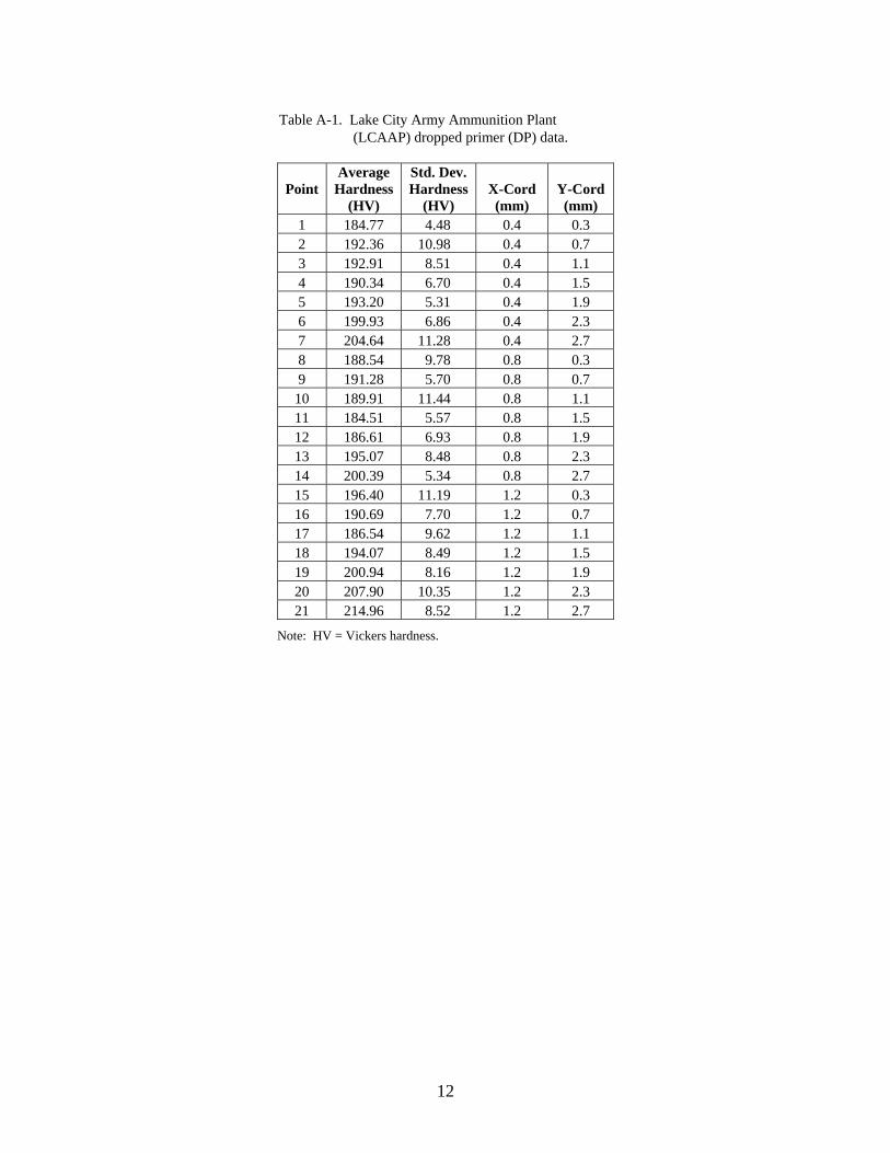
Table A-1. Lake City Army Ammunition Plant (LCAAP) dropped primer (DP) data. ...............12
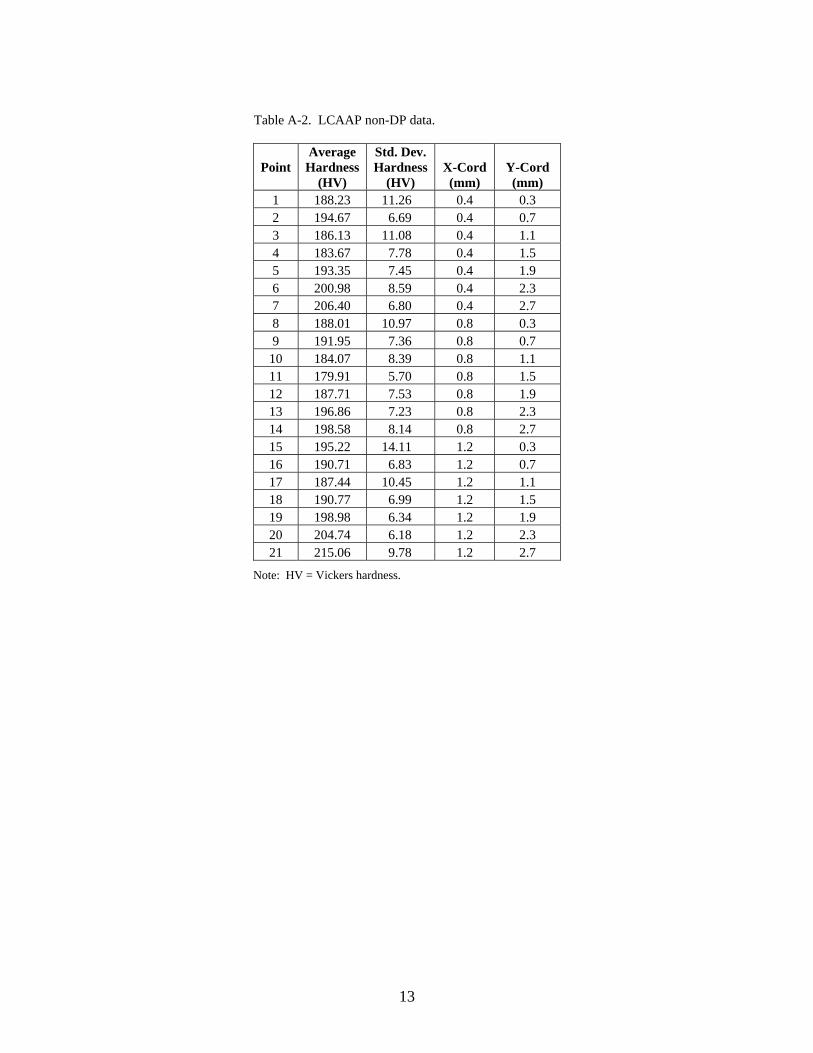
Table A-2. LCAAP non-DP data. .................................................................................................13
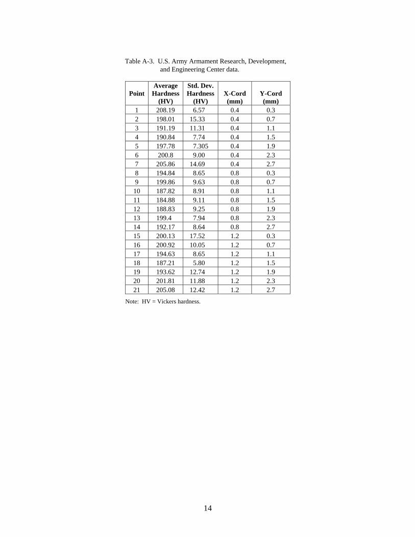
Table A-3. U.S. Army Armament Research, Development, and Engineering Center data. .........14

v
Acknowledgments
The authors would like to thank the Program Manager - Maneuver Ammunition Systems for their support and funding of this research. Their support has been invaluable to the development of the technology documented in this report. In addition, the authors would like to thank Lake City Army Ammunition Plant and the U.S. Army Armament Research, Development, and Engineering Center for providing samples to evaluate.

vi
INTENTIONALLY LEFT BLANK.
1
1. Introduction
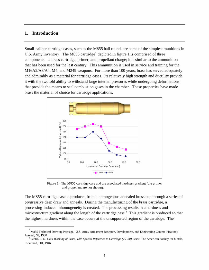
Small-caliber cartridge cases, such as the M855 ball round, are some of the simplest munitions in U.S. Army inventory. The M855 cartridge1 depicted in figure 1 is comprised of three components—a brass cartridge, primer, and propellant charge; it is similar to the ammunition that has been used for the last century. This ammunition is used in service and training for the M16A2/A3/A4, M4, and M249 weapons. For more than 100 years, brass has served adequately and admirably as a material for cartridge cases. Its relatively high strength and ductility provide it with the twofold ability to withstand large internal pressures while undergoing deformations that provide the means to seal combustion gases in the chamber. These properties have made brass the material of choice for cartridge applications.
Figure 1. The M855 cartridge case and the associated hardness gradient (the primer and propellant are not shown).
The M855 cartridge case is produced from a homogenous annealed brass cup through a series of progressive deep draw and anneals. During the manufacturing of the brass cartridge, a processing-induced inhomogeneity is created. The processing results in a hardness and microstructure gradient along the length of the cartridge case.2 This gradient is produced so that the highest hardness within the case occurs at the unsupported region of the cartridge. The
1 M855 Technical Drawing Package. U.S. Army Armament Research, Development, and Engineering Center: Picatinny
Arsenal, NJ, 1980. 2 Gibbs, L. E. Cold Working of Brass, with Special Reference to Cartridge (70–30) Brass; The American Society for Metals,
Cleveland, OH, 1946.
80
100
120
140
160
180
200
220
0.0 10.0 20.0 30.0 40.0 50.0
Location on Cartridge Case [mm]
Vic
kers
Ha
rdn
ess
, 2.5
kg
Lo
ad
[HV
]
Max Min
2
lowest hardness occurs in the neck region to allow for bullet crimping and detachment from the cartridge during firing.
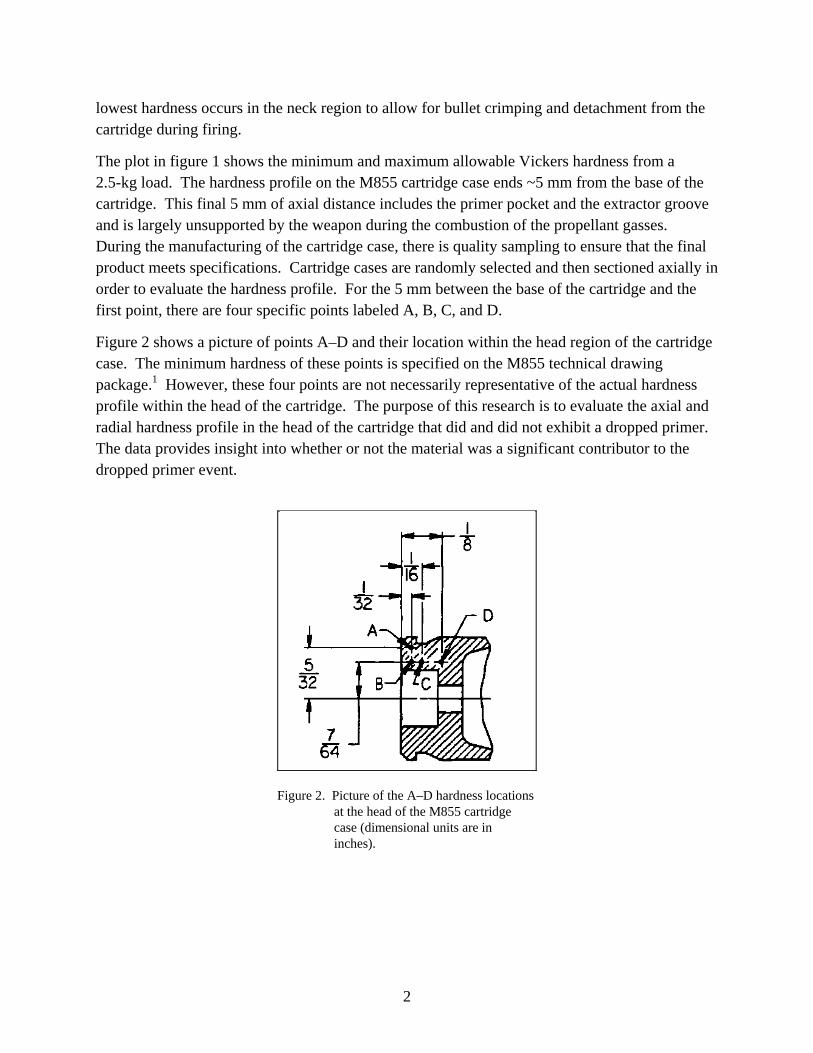
The plot in figure 1 shows the minimum and maximum allowable Vickers hardness from a 2.5-kg load. The hardness profile on the M855 cartridge case ends ~5 mm from the base of the cartridge. This final 5 mm of axial distance includes the primer pocket and the extractor groove and is largely unsupported by the weapon during the combustion of the propellant gasses. During the manufacturing of the cartridge case, there is quality sampling to ensure that the final product meets specifications. Cartridge cases are randomly selected and then sectioned axially in order to evaluate the hardness profile. For the 5 mm between the base of the cartridge and the first point, there are four specific points labeled A, B, C, and D.
Figure 2 shows a picture of points A–D and their location within the head region of the cartridge case. The minimum hardness of these points is specified on the M855 technical drawing package.1 However, these four points are not necessarily representative of the actual hardness profile within the head of the cartridge. The purpose of this research is to evaluate the axial and radial hardness profile in the head of the cartridge that did and did not exhibit a dropped primer. The data provides insight into whether or not the material was a significant contributor to the dropped primer event.
Figure 2. Picture of the A–D hardness locations at the head of the M855 cartridge case (dimensional units are in inches).
3
2. Experimental
Hardness testing was conducted to create a radial and axial map of the M855 brass cartridge case base. The cartridge cases were separated into four distinctive groups. The groups were broken down by location, where the cartridge cases were fired, and whether or not the cartridge cases exhibited a dropped primer.
2.1 Aliant Techsystems Inc. Samples
M855 standard cartridges were tested using standard Lake City Army Ammunition Plant (LCAAP) techniques for evaluating cartridge function. Testing was conducted at ambient temperatures using a M16A2 rifle. Cartridges were inspected after firing, and samples of cartridges that did and did not exhibit a dropped primer were collected. These cartridges cases were taken to building 2 at LCAAP, sectioned in half by wire EDM, and then sent to the metallography laboratory at LCAAP for mounting and polishing. The sectioned samples were mounted in rectangular plastic roughly the shape of the case. The plastic mounting media was a clear fast-setting acrylic cold mount. Polishing was performed in a series of progressive steps: 120-, 320-, and 600-grit sandpaper followed by 6-µm alumina and 0.3-µm alumina powder. All of the polishing was done by hand. There were 14 samples for each of the two LCAAP data sets.
2.2 ARDEC Samples
Sectioned M855 standard cartridges were received from the U.S. Army Armament Research, Development, and Engineering Center (ARDEC). The cartridge cases were sectioned into slivers ~3.175 mm in thickness. These samples were from unfired M855 cartridge cases produced by LCAAP and shipped to ARDEC. The M855 cartridge slivers were hot mounted in epoxy resin using a Struers Prestopress-3. Ten samples were taken to a 1-µm finish through grinding and polishing on a Struers Planopol-2 (with a speed of 300 rpm and ranging from 500 to 4000 grit).
2.3 Hardness Testing
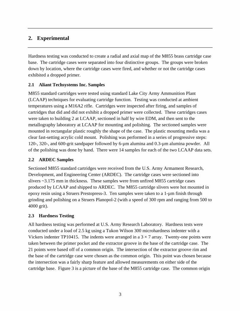
All hardness testing was performed at U.S. Army Research Laboratory. Hardness tests were conducted under a load of 2.5 kg using a Tukon Wilson 300 microhardness indenter with a Vickers indenter TP10415. The indents were arranged in a 3 × 7 array. Twenty-one points were taken between the primer pocket and the extractor groove in the base of the cartridge case. The 21 points were based off of a common origin. The intersection of the extractor groove rim and the base of the cartridge case were chosen as the common origin. This point was chosen because the intersection was a fairly sharp feature and allowed measurements on either side of the cartridge base. Figure 3 is a picture of the base of the M855 cartridge case. The common origin
4
Figure 3. Cross section of a base of a M855 cartridge showing the common origin axes.
is shown by the red-dashed axes. In order to create the 3 × 7array, a radial and axial spacing of 0.4 mm between points was applied. The first point in the array had coordinates of 0.4 and 0.3 mm.
3. Experimental Results for Hardness Testing
The results of the hardness testing on all of the cartridges cases are shown in figures 4–9. In all of the plots, the error bars represent standard deviation. The data presented in these figures is in table form in the appendix.
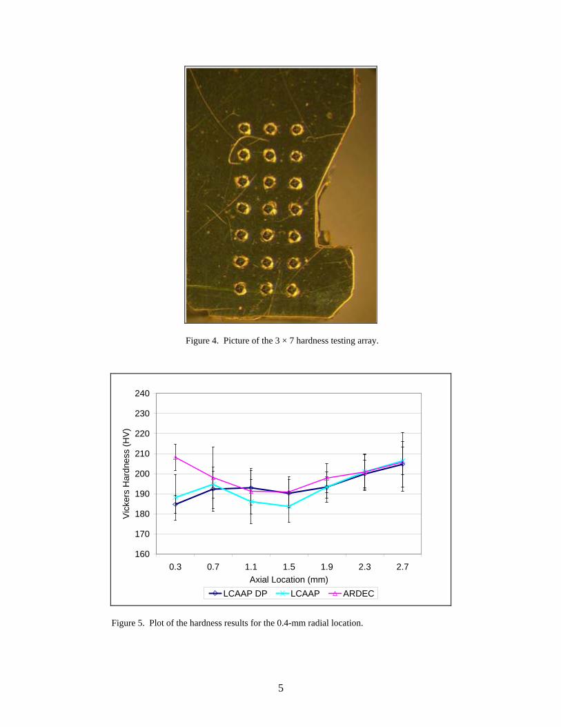
A picture of the 3 × 7 hardness testing array on the cartridge case base is shown in figure 4. The figure shows the uniform spacing of the array and the initial offset of the first point in the array from the common origin. The picture shows that the resulting material buildup due to the hardness test does not begin to encroach on the neighboring indents in the test array.
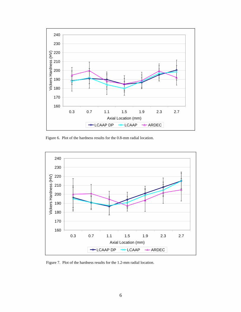
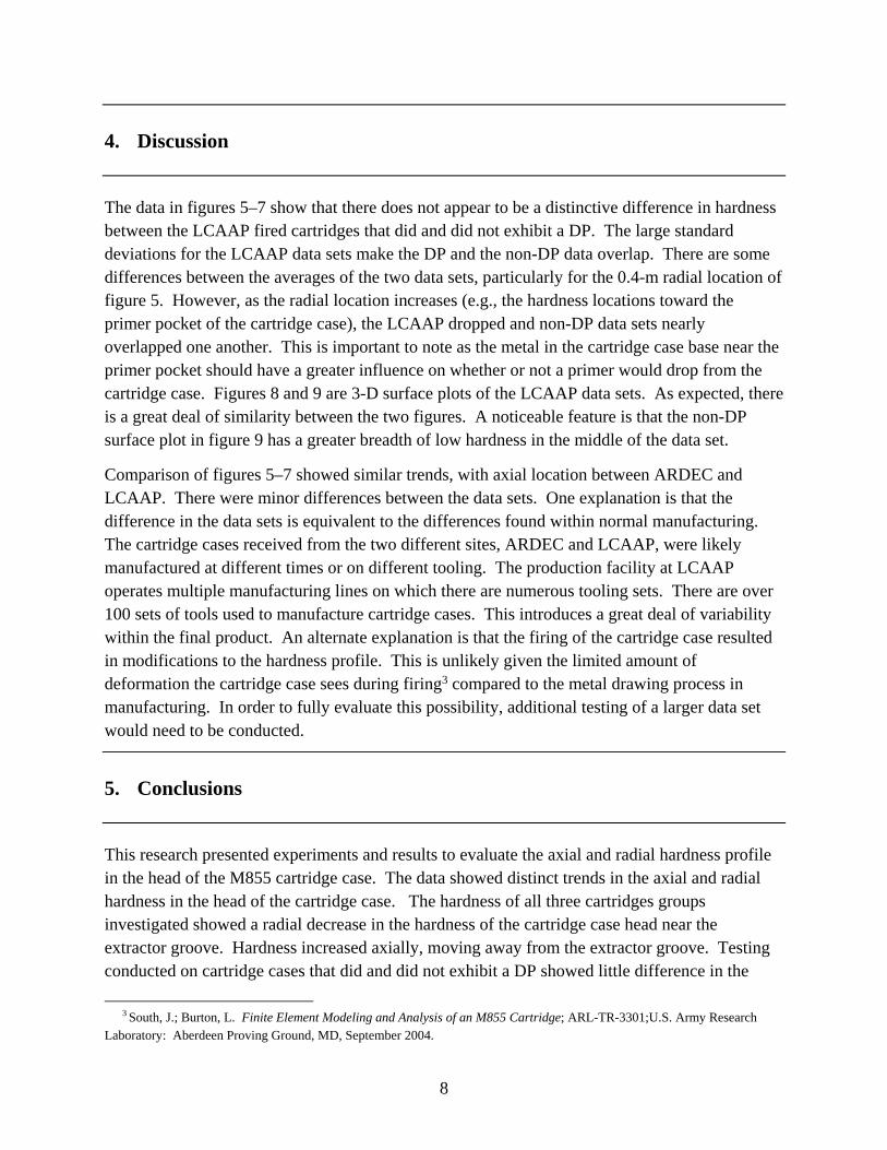
Figures 5–7 present the plots of the Vickers hardness as a function of the axial location for the three radial locations on the cartridge base. The plots show hardness measurements obtained from the LCAAP cartridges roughly track one another. This is true for all three radial locations, where the hardness initially decreases and then increases with increasing axial location. The initial decrease in the hardness correlates with the location of the extractor groove in the cartridge case. The higher hardness values correlate with the thicker cartridge wall locations at the extractor lip and ramp cartridge wall thickness forward of the extractor groove.
The hardness data from the ARDEC cartridge slivers does not match as well with the LCAAP data. Figure 5 shows a higher initial hardness valve for the 0.3 axial locations across all three radial locations within the array. After this value, the trend for the ARDEC data roughly matches the LCAAP data. The ARDEC and the LCAAP data sets all show a slight decrease in the Vickers hardness for the axial points near the extractor groove.
5
Figure 4. Picture of the 3 × 7 hardness testing array.
Figure 5. Plot of the hardness results for the 0.4-mm radial location.
160
170
180
190
200
210
220
230
240
0.3 0.7 1.1 1.5 1.9 2.3 2.7
Axial Location (mm)
Vic
kers
Har
dnes
s (H
V)
LCAAP DP LCAAP ARDEC
6
Figure 6. Plot of the hardness results for the 0.8-mm radial location.
Figure 7. Plot of the hardness results for the 1.2-mm radial location.
160
170
180
190
200
210
220
230
240
0.3 0.7 1.1 1.5 1.9 2.3 2.7
Axial Location (mm)
Vic
kers
Har
dnes
s (H
V)
LCAAP DP LCAAP ARDEC
160
170
180
190
200
210
220
230
240
0.3 0.7 1.1 1.5 1.9 2.3 2.7
Axial Location (mm)
Vic
kers
Har
dnes
s (H
V)
LCAAP DP LCAAP ARDEC

7
Figure 8. The three-dimensional (3-D) surface plot of the LCAAP dropped primer (DP) data.
Figure 9. The 3-D surface plot of the LCAAP non-DP data.
0.3
0.7
1.1
1.5
1.9
2.3
2.7
0.4
0.8
1.2
160
170
180
190
200
210
220
230
240
Vic
kers
Ha
rdn
ess
(H
V)
Axial Location (mm)
Radial Location
(mm)
230-240
220-230
210-220
200-210
190-200
180-190
170-180
160-170
0.3
0.7
1.1
1.5
1.9
2.3
2.7
0.4
0.8
1.2
160
170
180
190
200
210
220
230
240V
icke
rs H
ard
ne
ss (
HV
)
Axial Location (mm)
Radial Location
(mm)
230-240
220-230
210-220
200-210
190-200
180-190
170-180
160-170
8
4. Discussion
The data in figures 5–7 show that there does not appear to be a distinctive difference in hardness between the LCAAP fired cartridges that did and did not exhibit a DP. The large standard deviations for the LCAAP data sets make the DP and the non-DP data overlap. There are some differences between the averages of the two data sets, particularly for the 0.4-m radial location of figure 5. However, as the radial location increases (e.g., the hardness locations toward the primer pocket of the cartridge case), the LCAAP dropped and non-DP data sets nearly overlapped one another. This is important to note as the metal in the cartridge case base near the primer pocket should have a greater influence on whether or not a primer would drop from the cartridge case. Figures 8 and 9 are 3-D surface plots of the LCAAP data sets. As expected, there is a great deal of similarity between the two figures. A noticeable feature is that the non-DP surface plot in figure 9 has a greater breadth of low hardness in the middle of the data set.
Comparison of figures 5–7 showed similar trends, with axial location between ARDEC and LCAAP. There were minor differences between the data sets. One explanation is that the difference in the data sets is equivalent to the differences found within normal manufacturing. The cartridge cases received from the two different sites, ARDEC and LCAAP, were likely manufactured at different times or on different tooling. The production facility at LCAAP operates multiple manufacturing lines on which there are numerous tooling sets. There are over 100 sets of tools used to manufacture cartridge cases. This introduces a great deal of variability within the final product. An alternate explanation is that the firing of the cartridge case resulted in modifications to the hardness profile. This is unlikely given the limited amount of deformation the cartridge case sees during firing3 compared to the metal drawing process in manufacturing. In order to fully evaluate this possibility, additional testing of a larger data set would need to be conducted.
5. Conclusions
This research presented experiments and results to evaluate the axial and radial hardness profile in the head of the M855 cartridge case. The data showed distinct trends in the axial and radial hardness in the head of the cartridge case. The hardness of all three cartridges groups investigated showed a radial decrease in the hardness of the cartridge case head near the extractor groove. Hardness increased axially, moving away from the extractor groove. Testing conducted on cartridge cases that did and did not exhibit a DP showed little difference in the
3 South, J.; Burton, L. Finite Element Modeling and Analysis of an M855 Cartridge; ARL-TR-3301;U.S. Army Research
Laboratory: Aberdeen Proving Ground, MD, September 2004.

9
radial and axial hardness. The data provided insight into whether or not the material was a significant contributor to the DP event. The data between the fired and the unfired cartridges cases showed similar trends, but small differences in the averages were noted. The difference in these data sets was from normal manufacturing and lot-to-lot variation.

10
INTENTIONALLY LEFT BLANK.
11
Appendix. Hardness Testing Data
12
Table A-1. Lake City Army Ammunition Plant (LCAAP) dropped primer (DP) data.
Point Average
Hardness (HV)
Std. Dev. Hardness
(HV) X-Cord (mm)
Y-Cord (mm)
1 184.77 4.48 0.4 0.3 2 192.36 10.98 0.4 0.7 3 192.91 8.51 0.4 1.1 4 190.34 6.70 0.4 1.5 5 193.20 5.31 0.4 1.9 6 199.93 6.86 0.4 2.3 7 204.64 11.28 0.4 2.7 8 188.54 9.78 0.8 0.3 9 191.28 5.70 0.8 0.7
10 189.91 11.44 0.8 1.1 11 184.51 5.57 0.8 1.5 12 186.61 6.93 0.8 1.9 13 195.07 8.48 0.8 2.3 14 200.39 5.34 0.8 2.7 15 196.40 11.19 1.2 0.3 16 190.69 7.70 1.2 0.7 17 186.54 9.62 1.2 1.1 18 194.07 8.49 1.2 1.5 19 200.94 8.16 1.2 1.9 20 207.90 10.35 1.2 2.3 21 214.96 8.52 1.2 2.7
Note: HV = Vickers hardness.
13
Table A-2. LCAAP non-DP data.
Point Average
Hardness (HV)
Std. Dev. Hardness
(HV) X-Cord (mm)
Y-Cord (mm)
1 188.23 11.26 0.4 0.3 2 194.67 6.69 0.4 0.7 3 186.13 11.08 0.4 1.1 4 183.67 7.78 0.4 1.5 5 193.35 7.45 0.4 1.9 6 200.98 8.59 0.4 2.3 7 206.40 6.80 0.4 2.7 8 188.01 10.97 0.8 0.3 9 191.95 7.36 0.8 0.7
10 184.07 8.39 0.8 1.1 11 179.91 5.70 0.8 1.5 12 187.71 7.53 0.8 1.9 13 196.86 7.23 0.8 2.3 14 198.58 8.14 0.8 2.7 15 195.22 14.11 1.2 0.3 16 190.71 6.83 1.2 0.7 17 187.44 10.45 1.2 1.1 18 190.77 6.99 1.2 1.5 19 198.98 6.34 1.2 1.9 20 204.74 6.18 1.2 2.3 21 215.06 9.78 1.2 2.7
Note: HV = Vickers hardness.
14
Table A-3. U.S. Army Armament Research, Development, and Engineering Center data.
Point Average
Hardness (HV)
Std. Dev. Hardness
(HV) X-Cord (mm)
Y-Cord (mm)
1 208.19 6.57 0.4 0.3 2 198.01 15.33 0.4 0.7 3 191.19 11.31 0.4 1.1 4 190.84 7.74 0.4 1.5 5 197.78 7.305 0.4 1.9 6 200.8 9.00 0.4 2.3 7 205.86 14.69 0.4 2.7 8 194.84 8.65 0.8 0.3 9 199.86 9.63 0.8 0.7
10 187.82 8.91 0.8 1.1 11 184.88 9.11 0.8 1.5 12 188.83 9.25 0.8 1.9 13 199.4 7.94 0.8 2.3 14 192.17 8.64 0.8 2.7 15 200.13 17.52 1.2 0.3 16 200.92 10.05 1.2 0.7 17 194.63 8.65 1.2 1.1 18 187.21 5.80 1.2 1.5 19 193.62 12.74 1.2 1.9 20 201.81 11.88 1.2 2.3 21 205.08 12.42 1.2 2.7
Note: HV = Vickers hardness.
NO. OF COPIES ORGANIZATION
15
1 DEFENSE TECHNICAL (PDF INFORMATION CTR only) DTIC OCA 8725 JOHN J KINGMAN RD STE 0944 FORT BELVOIR VA 22060-6218 1 DIRECTOR US ARMY RESEARCH LAB IMNE ALC HRR 2800 POWDER MILL RD ADELPHI MD 20783-1197 1 DIRECTOR US ARMY RESEARCH LAB AMSRD ARL CI OK TL 2800 POWDER MILL RD ADELPHI MD 20783-1197 1 DIRECTOR US ARMY RESEARCH LAB AMSRD ARL CI OK PE 2800 POWDER MILL RD ADELPHI MD 20783-1197
ABERDEEN PROVING GROUND 1 DIR USARL AMSRD ARL CI OK TP (BLDG 4600)
NO. OF NO. OF COPIES ORGANIZATION COPIES ORGANIZATION
16
1 DIRECTOR US ARMY RSRCH LAB AMSRD ARL SE DE R ATKINSON 2800 POWDER MILL RD ADELPHI MD 20783-1197 6 DIRECTOR US ARMY RSRCH LAB AMSRD ARL WM MB A ABRAHAMIAN M BERMAN M CHOWDHURY A FRYDMAN R KARGUS T LI 2800 POWDER MILL RD ADELPHI MD 20783-1197 1 COMMANDER US ARMY MATRL CMND AMXMI INT 9301 CHAPEK RD FORT BELVOIR VA 22060-5527 1 COMMANDER US ARMY TACOM ARDEC AMSRD AAR EM J HEDDERICH PICATINNY ARSENAL NJ 07806-5000 1 COMMANDER US ARMY TACOM ARDEC AMSRD AAR EMT B MACHAK PICATINNY ARSENAL NJ 07806-5000 5 COMMANDER US ARMY TACOM ARDEC AMSRD AAR AEP E D CARLUCCI K LAUGHLIN S GROESCHLER J LEE J VEGA BLDG 94 PICATINNY ARSENAL NJ 07806-5000 1 COMMANDER US ARMY TACOM ARDEC AMSRD AAR AEW M(D) M MINISI BLDG 65 N PICATINNY ARSENAL NJ 07806-5000
8 COMMANDER US ARMY TACOM ARDEC AMSRD AAR AEM M PALATHINGUL A VELLA L MANOLE S MUSALLI M LUCIANO E LOGSDEN T LOUZEIRO J LUTZ PICATINNY ARSENAL NJ 07806-5000 2 COMMANDER US ARMY TACOM ARDEC AMSRD AAR AEE P D KAPOOR S KERWIEN PICATINNY ARSENAL NJ 07806-5000 2 SFSJM CDL AMMUN TEAM AMSIO SMT R CRAWFORD W HARRIS 1 ROCK ISLAND ARSENAL ROCK ISLAND IL 61299-6000
1 COMMANDER US ARMY TACOM ARDEC AMSTA AR CCL B J MIDDLETON BLDG 65N PICATINNY ARSENAL NJ 07806-5000 1 COMMANDER US ARMY TACOM ARDEC ASIC PRGM INTEGRATION OFC J RESCH BLDG 1 PICATINNY ARSENAL NJ 07806-5000 1 US ARMY ARDEC AMSRD AAR AEM I D CONWAY BLDG 65 N PICATINNY ARSENAL NJ 07806-5000 1 PM ARMS SFAE AMO MAS MC BLDG 354 PICATINNY ARSENAL NJ 07806-5000
NO. OF NO. OF COPIES ORGANIZATION COPIES ORGANIZATION
17
4 PM ARMS SFAE AMO MAS SMC R KOWALSKI F HANZL P RIGGS M BULTER BLDG 354 PICATINNY ARSENAL NJ 07806-5000 1 ALLIANT TECHSYSTEMS INC D KAMDAR MN11 2830 600 SECOND ST NE HOPKINS MN 55343 1 ATK LAKE CITY SMALL CALIBER AMMUN LAKE CITY ARMY AMMUN PLANT D MANSFIELD PO BOX 1000 INDEPENDENCE MO 64051-1000 1 ATK LAKE CITY LAKE CITY ARMY AMMUN PLANT SMALL CALIBER AMMUN J WESTBROOK MO10 003 PO BOX 1000 INDEPENDENCE MO 64051-1000 1 DIRECTOR US ARMY RESEARCH LAB AMSRD ARL CI R NAMBURU 2800 POWDER MILL RD ADELPHI MD 20783-1197
ABERDEEN PROVING GROUND 1 US ARMY ATC CSTE DTC AT AD I W FRAZER 400 COLLERAN RD APG MD 21005-5059 35 DIR USARL AMSRD ARL O AP EG FI M ADAMSON AMSRD ARL WM J SMITH S KARNA J MCCAULEY
P PLOSTINS T WRIGHT AMSRD ARL WM B M ZOLTOSKI J NEWILL AMSRD ARL WM BA D LYON AMSRD ARL WM BC P WEINACHT AMSRD ARL WM BD B FORCH P CONROY AMSRD ARL WM BF W OBERLE AMSRD ARL WM M S MCKNIGHT J BEATTY R DOWDING AMSRD ARL WM MA M VANLANDINGHAM AMSRD ARL WM MB J BENDER R CARTER W DRYSDALE R KASTE J SOUTH AMSRD ARL WM MC E CHIN J MONTGOMERY AMSRD ARL WM MD M MAHER AMSRD ARL WM T P BAKER AMSRD ARL WM TA S SCHOENFELD AMSRD ARL WM TB J COLBURN AMSRD ARL WM TC R COATES T EHLERS L MAGNESS B SCHUSTER AMSRD ARL WM TD T BJERKE T WEERASOORIYA AMSRD ARL WM TE B RINGERS

18
INTENTIONALLY LEFT BLANK.