Vickers ‘E’ Series Piston Pumpspub/@eaton/@hyd/... · eaton Vickers ‘E’ Series Piston Pumps...
30
Vickers ® ‘E’ Series Piston Pumps PVE012, PVE19, PVE21
Transcript of Vickers ‘E’ Series Piston Pumpspub/@eaton/@hyd/... · eaton Vickers ‘E’ Series Piston Pumps...
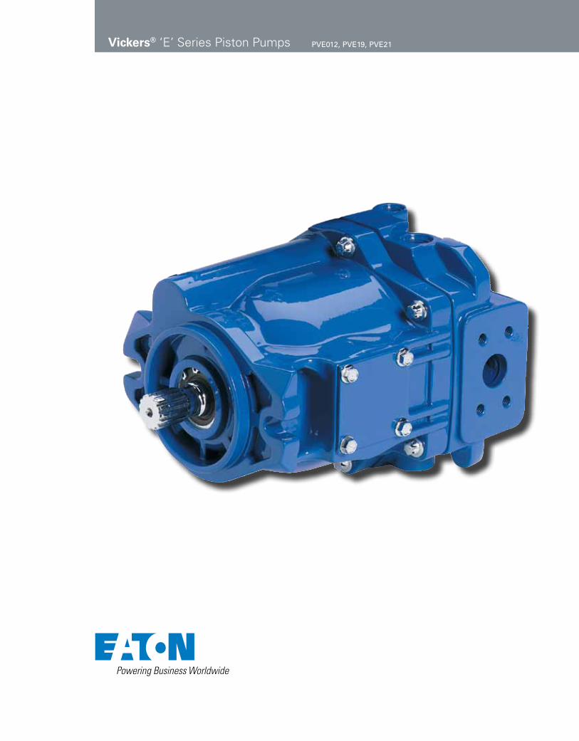
Vickers® ‘E’ Series Piston Pumps PVE012, PVE19, PVE21

eaton Vickers ‘E’ Series Piston Pumps V-PUPI-TM010-E December 2009 2
eaton Vickers ‘E’ Series Piston Pumps V-PUPI-TM010-E December 2009 3
Table of Contents
Introduction . . . . . . . . . . . . . . . . . . . . . . . . . . . . . . . . . . . . . . . . . . . . . . . . . . . . . . . . . . . . . . . . . . . . . . . . . . . 4
Controls . . . . . . . . . . . . . . . . . . . . . . . . . . . . . . . . . . . . . . . . . . . . . . . . . . . . . . . . . . . . . . . . . . . . . . . . . . . . . 5
Operating Data . . . . . . . . . . . . . . . . . . . . . . . . . . . . . . . . . . . . . . . . . . . . . . . . . . . . . . . . . . . . . . . . . . . . . . . . 6
Displacement, Speed, and Pressure Ratings Overspeed Limits
PVE012
Model Number System . . . . . . . . . . . . . . . . . . . . . . . . . . . . . . . . . . . . . . . . . . . . . . . . . . . . . . . . . . . . . . . . . 8
Shaft Torque Data . . . . . . . . . . . . . . . . . . . . . . . . . . . . . . . . . . . . . . . . . . . . . . . . . . . . . . . . . . . . . . . . . . . . . 8
Performance Curves . . . . . . . . . . . . . . . . . . . . . . . . . . . . . . . . . . . . . . . . . . . . . . . . . . . . . . . . . . . . . . . . . . . . 9
Installation Dimensions . . . . . . . . . . . . . . . . . . . . . . . . . . . . . . . . . . . . . . . . . . . . . . . . . . . . . . . . . . . . . . . . 10
Shaft Options . . . . . . . . . . . . . . . . . . . . . . . . . . . . . . . . . . . . . . . . . . . . . . . . . . . . . . . . . . . . . . . . . . . . . . . . 10
Controls . . . . . . . . . . . . . . . . . . . . . . . . . . . . . . . . . . . . . . . . . . . . . . . . . . . . . . . . . . . . . . . . . . . . . . . . . . . . . 11
Adjustable Maximum Volume Stop Load Sensing with Pressure Limiter Remote Adjustment Compensator
PVE19/21
Model Number System . . . . . . . . . . . . . . . . . . . . . . . . . . . . . . . . . . . . . . . . . . . . . . . . . . . . . . . . . . . . . . . . 14
Shaft Torque Data . . . . . . . . . . . . . . . . . . . . . . . . . . . . . . . . . . . . . . . . . . . . . . . . . . . . . . . . . . . . . . . . . . . . 16
Typical Rear Pumps for Thru-drives . . . . . . . . . . . . . . . . . . . . . . . . . . . . . . . . . . . . . . . . . . . . . . . . . . . . . . 16
Performance Curves . . . . . . . . . . . . . . . . . . . . . . . . . . . . . . . . . . . . . . . . . . . . . . . . . . . . . . . . . . . . . . . . . . . 17
PVE19 PVE21
Installation Dimensions . . . . . . . . . . . . . . . . . . . . . . . . . . . . . . . . . . . . . . . . . . . . . . . . . . . . . . . . . . . . . . . . 19
Side Ports and C-type Control End Ports and C-type Control
Controls . . . . . . . . . . . . . . . . . . . . . . . . . . . . . . . . . . . . . . . . . . . . . . . . . . . . . . . . . . . . . . . . . . . . . . . . . . . . 21
Adjustable Maximum Volume Stop Load Sensing with Pressure Limiter Remote Adjustment Compensator Unloading ValveShaft Options . . . . . . . . . . . . . . . . . . . . . . . . . . . . . . . . . . . . . . . . . . . . . . . . . . . . . . . . . . . . . . . . . . . . . . . . 24
Thru-drives . . . . . . . . . . . . . . . . . . . . . . . . . . . . . . . . . . . . . . . . . . . . . . . . . . . . . . . . . . . . . . . . . . . . . . . . . . 25
PVE19/21 SAE “A” PVE19/21 SAE “B”
Application Data . . . . . . . . . . . . . . . . . . . . . . . . . . . . . . . . . . . . . . . . . . . . . . . . . . . . . . . . . . . . . . . . . . . . . 28

eaton Vickers ‘E’ Series Piston Pumps V-PUPI-TM010-E December 2009 4
Introduction to PVE Piston Pumps
Eaton PVE piston pumps are inline, variable displacement pumps that are available in three displacement sizes. An assortment of optional controls offer maximum operating flexibility.
Pump displacement is varied by means of pressure and/or flow compensator controls.
PVE012 Section View
Yoke
Housing Compensator
Valve Block
ShaftSeal
Shaft
Bearing Piston
Figure 1. Sectional Views of the PVE Pumps
Drive Shaft
PVE012 Section View
HousingRotating Group
Tapered RollerBearing
Yoke Wafer Plate Compensator
Features and Benefits
• Inline, variable displacement pump
• Displacement is varied by pressure/flow compensator controls
• Optional controls for
maximum operating flexibility
• Thru-drive available on PVE 19/21

eaton Vickers ‘E’ Series Piston Pumps V-PUPI-TM010-E December 2009 5
Controls
Pressure Compensator Control, “A” Option
This control automatically varies pump displacement to meet the system flow demand for a constant system pressure. Dis placement starts to reduce to zero within 14 bar (200 psi) of the com-pensator setting. Power draw-off is minimized, therefore, system relief valves should not be required.
Pressure Compensator Control with Maximum Displacement Adjustment
As indicated for “A” option above, except there is an independent screw adjustment of maximum displacement from 100% (rated) to 25%.
Load Sensing Compensator and Pressure Limiter, “B” Option
This compensator provides load sensing control under all pressure conditions up to the desired maximum. It automatically adjusts pump flow in response to a remote pressure signal and maintains outlet pressure at approximately 11 bar (160 psi) above load pres-sure. The integral pressure limiter overrides the load sensing control, reducing pump displacement as the preset maximum operat-ing pressure is reached. Override begins within 14 bar (200 psi) of the preset maximum pressure com-pensator setting. A 24 bar LS option is also available.
PVE with Pressure Compensator Arranged for Remote Control, “D” Option or “J” Option
Exactly the same as the “A” (pressure compensa-tion option) except the machine operator is able to change the compensator setting through the use of a remote pilot relief valve.
Note: Graphic symbols shown with external valve(s) and cylinder to illustrate typical usage.
Note: Optional internal bleed orifice diameter is .015’’ and is “A” option-control special features.
Note: A kit is available for an electrical dual pressure com pensator. This control automatically adjusts pump delivery to maintain system volume requirements at either of two preselected operating pressures. This allows lower settings for low horsepower start-up, equipment testing, etc. This kit also allows for higher pressure settings as required in machine appli-cations. For details refer to service drawing I-3255-S.

eaton Vickers ‘E’ Series Piston Pumps V-PUPI-TM010-E December 2009 6
Operating DataDisplacement Speed, and Pressure Ratings
Displacement, Speed and Pressure Ratings
Model Number Displacement cm3/r (in3/r) Rated Input Speed Maximum PressureSystem Shaft End Pump Cover End Pump (At 0 psig Inlet) bar (psi) PVE012 25 (1.54) – 3000 210(3000) PVE19 41 (2.50) – 2400 210(3000) PVE21 45 (2.75) – 2400 186(2700)
Pressure Limits
Port Pressure RangeInlet** 0,2 bar to 2,0 bar (5 in. Hg. vacuum to 30 psi)Outlet See Maximum Pressures listed aboveDrain* 0,35 bar (5 psig) maximum
** Integral relief valve protects pump by limiting case pressure peaks to 0,7 bar (10 psi) above inlet pressure. Flow from valve returned directly to pump inlet. Case drain line required to limit steady-state case pressure.
** See page 9 for Inlet vs. Speed details. For non-intergrated units only
Preparation for Start-up
Before starting a PVE pump, fill the case through the uppermost drain port with clean system hydrau-lic fluid. The case drain line must be connected to the reservoir below oil level. For multiple pump arrange-ments that include non-PVE sections, the requirements of the non-PVE units must also be considered.
Mounting
Eaton Hydraulics recom-mends these PVE series piston pumps be mounted horizontally.
** Shaded product may not be available

eaton Vickers ‘E’ Series Piston Pumps V-PUPI-TM010-E December 2009 7
Operating DataDisplacement Speed, and Pressure Ratings
at Full Flow Conditions
Displacement cm3/r (in3/r) Inlet Pressure/Vacuum* Maximum Speed** rpm
PVE21 full displacement 45 (2.75) 5 psig 2800
PVE19 full displacement 41 (2.50) 0 psig 2400
5 in. Hg. 2100 5 psig 3100PVE19/21 destroked 33 (2.00) 0 psig 2750 5 in. Hg. 2500 5 psig 3200PVE19/21 destroked 25 (1.50) 0 psig 3000 5 in. Hg. 2850
PVE012 limited to 3000 rpm at full displacement and 0 psig inlet.** Minimum pressure/vacuum required at pump inlet to operate at displacement and speed listed.** Speeds not listed, but within displacements shown above, may be calculated from values listed.
at Load Sense Standby Condition – “B” option Controls
Model Number System Maximum Speed rpmPVE012 3600PVE19 3200PVE21 3200
Pump must be in zero flow, low pressure, standby condition when operated at listed speed. Pump may be damaged if not slowed to normal rated speed before being operated at full flow.
Yoke response recorded at rated speed and pressure, 0 psi inlet, 82°C (180°F), SAE 10W oil. Pressure rise was 6900 bar (100,000 psi) per second.
Response Data
PVE012 PVE19/21
Control Type On Stroke sec. Off Stroke sec. On Stroke sec. Off Stroke sec.Pressure compensator 0.030 0.012 0.050 0.025Load sense compensator 0.040 0.012 0.060 0.020
Sound Data
1200 rpm, 70 bar (1000 psi) 1500 rpm, 140 bar (2000 psi) 1800 rpm, 210bar (3000 psi)
Model Full Full Full Number Stroke Compensated Stroke Compensated Stroke Compensated System dB(A) Stroke dB(A) dB(A) Stroke dB(A) dB(A) Stroke dB(A)PVE012 71 65 76 72 77 77PVE19 79 74 83 85 86 87PVE21 75 73 79 81 83* 83** 2700 psiSound level dB(A) per ISO 4412-1 standard.

eaton Vickers ‘E’ Series Piston Pumps V-PUPI-TM010-E December 2009 8
1, 2 Pump SeriesPV – Open Circuit Piston
Pump
3,4,5,6 Displacement E012 – 25.2cm3/r (1.54 in3/r)
7 Input Shaft Rotation R – Right-Hand Rotation
(cw)L – Left-Hand Rotation
(ccw)
8, 9 Front Mounting and Input Shaft
01 – SAE B 2 bolt, Keyed05 – SAE B 2 bolt, Splined
13t 16/32DP09 – SAE B 2 bolt, Splined
26t 32/64DP
10,11 Main Ports Location and Size
AU – End ports, SAE o-ring; #20 suction, #12 pressure
AV – End ports, ISO 6149; M42 suction, M27 pressure
12 Drain Port Size 06 – M18 metric O-ring
port – top (D1)07 – M18 metric O-ring
port – bottom (D2)
B – #8 SAE O-ring port – top (D1)
C – #8 SAE O-ring port – bottom (D2)
13 Diagnostic Pressure Port
0 – No diagnostic pressure port
14 Controller TypeA – Pressure Compensator B – Pressure and flow
compensator C – Electric dual range
pressure Compensator with directional control valve
D – Hydraulic remote con-trol pressure compen-sator
E – Unloading valve (accumulator Circuits)
F – Electric dual range pressure compensator without directional control valve
15,16 Pressure Comp./Un-loading Valve Setting
00 – No pressure compen-sator setting
33 – 207-214 bar (3000-3100 psi)
17,18 Flow Comp. Setting or Unload Valve
00 – No pressure compen-sator setting
11 – 9.65-12.41 bar (140-180 psi)
24 – 22.75-25.51 bar (330-370 psi)
19,20 Secondary Compen-sator Setting
00 – As Given in Code Title 21 Control Special Features0 – No Special FeaturesA – Bleed down orifice, LS onlyB – External load-sensing
adjustmentG – High rate spring for low
pressure settingJ – Bleed down orifice and
high rate spring for low pressure setting
22 Maximum Displace-ment Option
1 – Standard ajdustment
2 – Adjustable maximum displacement (set at maximum)
23,24 Auxiliary Mounting and Output Shaft
00 – No auxiliary mounting or output shaft
25 Shaft Seals0 – No shaft seal1 – Standard shaft seal
(nitrile)
26,27 Special Features00 – No special features
28,29 Paint00 – No paintCD – Blue primer
30 Customer and unit identification
0 – STD – mark assembly Number, full model code and build data Code on plate
31 Design CodeA – First
PV E012 R 00 1AU B 0 B 33 24 00 A 1 00 1 00 CD 0 A
7 12 2113 14 2522 30 311, 2 3,4,5,6 8,9 10,11 15,16 17, 18 19,20 23, 24 26, 27 28, 29
Model CodeE Series, PVE012 Pump
Note: Consult an Eaton representative for additional settings
PVe012 Shaft torque Data
Input Shaft Designation Thru-drive Option Maximum Input Torque N.m (lb.in.)01 SAE “B” straight keyed No 135 (1200)05 SAE “B” spline 13T, 16/32 D.P., FRMDF No 208 (1850)09 Special Eaton 26T for use in rear pump No N/A of tandem PVE**-PVE12 unit
Shaft Torque DataPVE012
eaton Vickers ‘E’ Series Piston Pumps V-PUPI-TM010-E December 2009 9
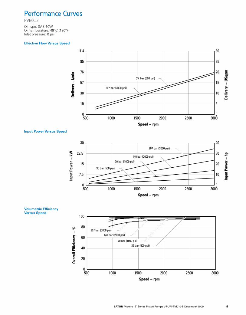
Performance CurvesPVE012Oil type: SAE 10W Oil temperature: 49°C (180°F) Inlet pressure: 0 psi
11 4
95
76
57
38
19
0
5
10
15
20
25
30
500 1000 1500 2000 2500 3000
Speed – rpm
Del
iver
y –
l/min
Del
iver
y –
USg
pm
0
30
22.5
15
7.5
0
10
20
30
40
500 1000 1500 2000 2500 3000
Speed – rpm
Inpu
t Pow
er–
kW
Inpu
t Pow
er –
hp
0
100
80
60
40
20
500 1000 1500 2000 2500 3000
Speed – rpm
Ove
rall
Effic
ienc
y –
%
0
35 bar (500 psi)
207 bar (3000 psi)
207 bar (3000 psi)
140 bar (2000 psi)
70 bar (1000 psi)
35 bar (500 psi)
207 bar (3000 psi)140 bar (2000 psi)
70 bar (1000 psi)35 bar (500 psi)
Effective Flow Versus Speed
Input Power Versus Speed
Volumetric Efficiency Versus Speed
11 4
95
76
57
38
19
0
5
10
15
20
25
30
500 1000 1500 2000 2500 3000
Speed – rpm
Del
iver
y –
l/min
Del
iver
y –
USg
pm
0
30
22.5
15
7.5
0
10
20
30
40
500 1000 1500 2000 2500 3000
Speed – rpm
Inpu
t Pow
er–
kW
Inpu
t Pow
er –
hp
0
100
80
60
40
20
500 1000 1500 2000 2500 3000
Speed – rpm
Ove
rall
Effic
ienc
y –
%
0
35 bar (500 psi)
207 bar (3000 psi)
207 bar (3000 psi)
140 bar (2000 psi)
70 bar (1000 psi)
35 bar (500 psi)
207 bar (3000 psi)140 bar (2000 psi)
70 bar (1000 psi)35 bar (500 psi)

eaton Vickers ‘E’ Series Piston Pumps V-PUPI-TM010-E December 2009 10
Installation DimensionsPVE012 with Pressure Compensator
27,0(1.06)
Alternate drain port "D1".750 - 16 UNF - 2B thd.SAE O–Ring boss connection .500 O.D. tubing
29,5 (1.16)
85,1(3.35)
170,2(6.70)
153,5(6.04)
Construction plugsDo not remove
51,5(2.03)
70,0(2.76)
73,0(2.87)
30,0(1.18) 19,5 R
(0.77 R)
120,6( 4.75)
14,0 R(0.55 R)
2 places
14,5314,15
(0.572)(0.557)
R.H. rotation
25,0(0.98)
146,0(5.75)
140,0(5.51)
101,60 101,55( 4.000)( 3.998)
14,0 (0.55)
9,4(0.37)
0,76(0.030)
max. R
167,5 (6.59)
196,6 (7.74)
162,5 (6.40)
186,1 (7.33)
47,0(1.85)
44,0(1.73)
44,0(1.73)
28,4(1.12)
56,0( 2.20)2 places
Compensatorposition R.H.rotation (reversefor L.H. rotation)
Drain port"D2" .750-16UNF-2B thd.SAE O-ringbossconnection.500 O.D.tubing
Outlet port (seenote) 1.0625-12UN-2B thd. SAEO-ring bossconnection .750O.D. tubing (shownfor R.H. rotation)
Inlet port(see note)1.625-12UN-2B thd.SAE O-ringbossconnection1.250 O.D.tubing
60,0(2.36)
83,1(3.27)
77,0(3.03)
154,0 (6.06)
114,1(4.49)
73,4(2.89)
52,0(2.05) 70,0
(2.76)
25,1224,87
(0.989)(0.979)
22,225 22,200
( 0.8750)( 0.8740)
6,3756,350(0.251)(0.250)
long key31,75(1.250)x
1.5(0.06)x 45
50.8(2.00)
58,6(2.31)
No. 1 Shaft: SAE " B" Straight Keyed
PVE12 Shaft Options
5,5(0.22)
SAE B modified involute spline(0.8585 – 0.8530 major diameter,0.715 minimum minor diameter).Flat root, side fit. Class 5 perANSI B92.1a–1976. 13 teeth,16/32 diameter pitch,30 pressure angle.
5,5(0.22)
1.5(0.06)
30
x 45 19,0
(0.75)
41,1(1.62)
33,3(1.31)
No. 2 Shaft: SAE " B" Splined
Note: Applications requiring overhung load or side loading of shaft are subject to Eaton engineering approval.
PVE012 Shaft Options#01: SAE “B” Straight Keyed #05: SAE “B” Splined

eaton Vickers ‘E’ Series Piston Pumps V-PUPI-TM010-E December 2009 11
ControlsPVE012See installation dimensions page 10 for other details.
52,0(2.05)72,6
(2.86) 90,1(3.55)
63,8(2.51)
28,4( 1.12)
123,8(4.87)
30,0(1.18)
250,1(9.85)218,2
(8.59)194,2(7.65)
11,8(0.43)max.
Maximum stopadjusting rod
(Approx. 2,22 cc/revchange per turn)
Compensator positionfor R.H. rotation
Compensator positionfor L.H. rotation
214,3(8.44)
28,4( 1.12)
19,0(0.75)
52,0(2.05)
128,3(5.05)
70,6(2.78)
191,0(7.52)
Load sensingcompensator
control port locationfor L.H. rotation
Compensatorposition forR.H. rotation
Load sensing compensator controlport location for R.H. rotation.4375-20 UNF-2B thd. SAE O-ringboss connection .250 O.D. tubing
68,3(2.69)
10,6(0.42)
Compensatorposition for
L.H. rotation
Locknut 11,2(0.44) across flats
Adjustment
Loosen the locknut on the adjusting rod. Turn the adjusting rod clockwise to decrease maximum pump delivery, or counterclock-wise to increase maximum pump delivery, until the desired setting is obtained. Secure the setting by tight-ening the locknut. To assist initial priming, the manual adjustment control setting must be at least 40% of the maximum flow posi-tion.
This control enables maxi-mum pump delivery to be externally adjusted from 25% to 100% while main-taining all the standard features of a pressure com-pensated pump.

eaton Vickers ‘E’ Series Piston Pumps V-PUPI-TM010-E December 2009 12
ControlsPVE012See installation dimensions page 10 for other details.
PVE012 Load Sensing with Pressure Limiter “A” Control Option
52,0(2.05)72,6
(2.86) 90,1(3.55)
63,8(2.51)
28,4( 1.12)
123,8(4.87)
30,0(1.18)
250,1(9.85)218,2
(8.59)194,2(7.65)
11,8(0.43)max.
Maximum stopadjusting rod
(Approx. 2,22 cc/revchange per turn)
Compensator positionfor R.H. rotation
Compensator positionfor L.H. rotation
214,3(8.44)
28,4( 1.12)
19,0(0.75)
52,0(2.05)
128,3(5.05)
70,6(2.78)
191,0(7.52)
Load sensingcompensator
control port locationfor L.H. rotation
Compensatorposition forR.H. rotation
Load sensing compensator controlport location for R.H. rotation.4375-20 UNF-2B thd. SAE O-ringboss connection .250 O.D. tubing
68,3(2.69)
10,6(0.42)
Compensatorposition for
L.H. rotation
Locknut 11,2(0.44) across flats
eaton Vickers ‘E’ Series Piston Pumps V-PUPI-TM010-E December 2009 13
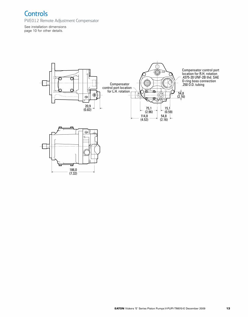
ControlsPVE012 Remote Adjustment CompensatorSee installation dimensions page 10 for other details.
186,0(7.32)
20,9(0.82)
114,8(4.52)
75,1(2.96)
15,1(0.59)
54,8(2.16)
54,8(2.16)
Compensator control portlocation for R.H. rotation.4375-20 UNF-2B thd. SAEO-ring boss connection.250 O.D. tubingCompensator
control port locationfor L.H. rotation

eaton Vickers ‘E’ Series Piston Pumps V-PUPI-TM010-E December 2009 14
1, 2 Pump SeriesPV – Open Circuit Piston
Pump
3,4,5,6 Displacement E19A – 41.0cm3/r (2.50 in3/r)E21A – 45.1cm3/r (2.75 in3/r)
7 Input Shaft Rotation R – Right-Hand Rotation
(cw)L – Left-Hand Rotation
(ccw)
8, 9 Front Mounting and Input Shaft
01 – SAE B 2 bolt, Keyed
02 – SAE B-B 2 bolt, Keyed
04 – SAE B 2 bolt, tapered
05 – SAE B 2 bolt, splined 13t 16/32DP long shaft
08 – SAE B-B 2 bolt, splined 15t 16/32DP
09 – SAE B 2 bolt, splined 26t 32/64DP
10,11 Main Ports Location and Size
AA – Side ports, SAE o-ring; #24 suction, #14 pressure
AB – End ports, SAE o-ring; #24 suction, #14 pressure
AC – Side ports, SAE 4 bolt flange, Code 61; 1 1/2” suction, 1” pressure
AD – End ports, SAE 4 bolt flange, Code 61; 1 1/2” suction, 1” pressure
AE – Side ports, ISO 6149-1; M48 suction, M33 pressure
AF – End ports, ISO 6149-1; M48 suction, M33 pressure
AS – End ports ISO 6162 4 bolt flange; 1 1/2” suction, 1” pressure
12 Drain Port Size and Location
01 – #10 SAE O-ring port – top (D1)
02 – #10 SAE O-ring port – bottom (D2)
06 – M18 metric O-ring port – top (D1)
07 – M18 metric O-ring port – bottom (D2)
13 Diagnostic Pressure Port
0 – No diagnostic pressure port
1 – #4 SAE O-ring port – plugged
2 – M14 metric O-ring port – plugged
14 Controller TypeA – Pressure Compensator B – Pressure and flow
compensator C – Electric dual range
pressure compensator with directional control valve
D – Hydraulic remote con-trol pressure compen-sator
E – Unloading valve (accumulator circuits)
F – Electric dual range pressure compensator without directional control valve
15,16 Pressure Comp./Un-loading Valve Setting
00 – No pressure compensator setting
18 – 182.7-189.6 bar (2650-2750 psi)
33 – 206.8-213.7 bar (3000-3100 psi)
17,18 Flow Comp. Setting or Unload Valve
00 – No pressure compensator setting
11 – 9.65-12.41 bar (140-180 psi)
14 – 12.41-15.17 bar (180-220 psi)
24 – 22.75-25.51 bar (330-370 psi)
19,20 Secondary Compen-sator Setting
00 – No secondary com-pensator setting
04 – 186.2-193.1 bar (2700-2800 psi)
21 Control Special Features0 – No Special FeaturesA – Bleed down orificeB – External load-sensing
adjustmentG – High rate spring for low
pressure settingJ – Bleed down orifice and
high rate spring for low pressure setting
PV E19A R 01 AA 1 0 B 33 24 00 A 1 AA 1 AF CD 0 A
7 12 2113 14 2522 30 311, 2 3,4,5,6 8,9 10,11 15,16 17, 18 19,20 23, 24 26, 27 28, 29
Model CodePVE19/21
Note: Consult an Eaton representative for additional settings

eaton Vickers ‘E’ Series Piston Pumps V-PUPI-TM010-E December 2009 15
22 Maximum Displacement Option
1 – Standard ajdustment
2 – Adjustable maximum displacement (set at maximum)
23,24 Auxiliary Mounting and Output Shaft
00 – No auxiliary mounting or output shaft
AA – SAE A 2 bolt w/ 9T 16/32DP external splined shaft
AB – 2 Bolt A (SAE J744-82-2) w/ 11T 16/32DP ex. splined shaft
AC – SAE B 2 bolt w/ 13T 16/32 DP internal splined coupling
AD – SAE B 2 bolt w/ 15T 16/32DP internal splined coupling
AE – SAE B 2 bolt w/ 26T 32/64DP external splined shaft
AH – SAE A 2 bolt w/ 9T 16/32DP internal splined coupling
AJ – SAE A 2 bolt w/ 11T 16/32DP internal splined coupling
AK – SAE B 2 bolt w/ 26T 32/64DP internal splined coupling
25 Shaft Seals0 – No shaft seal1 – Flurocarbon shaft seal
26,27 Special Features00 – No special featuresAA – Auxiliary mounting
cover plateAF – Cast iron housing
28,29 Paint00 – No paintCD – Blue primer
30 Customer and unit identification
0 – Standard Eaton identification
31 Design CodeA – First design
PV E19A R 01 AA 1 0 B 33 24 00 A 1 AA 1 AF CD 0 A
7 12 2113 14 2522 30 311, 2 3,4,5,6 8,9 10,11 15,16 17, 18 19,20 23, 24 26, 27 28, 29
Model CodePVE19/21
Note: Consult an Eaton representative for additional settings

eaton Vickers ‘E’ Series Piston Pumps V-PUPI-TM010-E December 2009 16
Shaft Torque DataPVE19/21
Typical Rear Pumps for Thru-drivesPVE19/21
Shaft torque Data
Input Thru-drive Maximum Spline Data Designation Option Torque N.m (lb.in.)02 SAE “BB” straight keyed Yes 215 (1900)08 SAE “BB” spline 15T, 16/32 D.P., FRSF Yes 337 (2987)05 SAE “B” spline 13T, 16/32 D.P., FRSF Yes 208 (1850)01 SAE “B” straight keyed No 135 (1200)09 Special Eaton 26T for use in rear pump No N/A of tandem PVE**-PVE** unitNote: See page 22 for more details.
typical Rear Pumps for thru-Drives
Model Code Typical Rear Pump Model Rear Pump Shaft Code PVE** Thru-drive CouplingAH PVQ10/13 3 PVB5/6 Suffix -S214 864224 V10 11 (9T / 9T Straight) V20 62AC PVE012 5 PVE19/21 5 PVQ20/32 3 864307 PVQ40/45 5 (26T / 13T Step) V2010 or V2020 11 20V(Q) 151AD PVE19/21 8 475134 PVQ40/45 8 (26T / 15T Step) 2520V(Q) 166AK PVE012 PVE19/21 9 627168 N/C / 26T Straight) PVQ40/45
eaton Vickers ‘E’ Series Piston Pumps V-PUPI-TM010-E December 2009 17
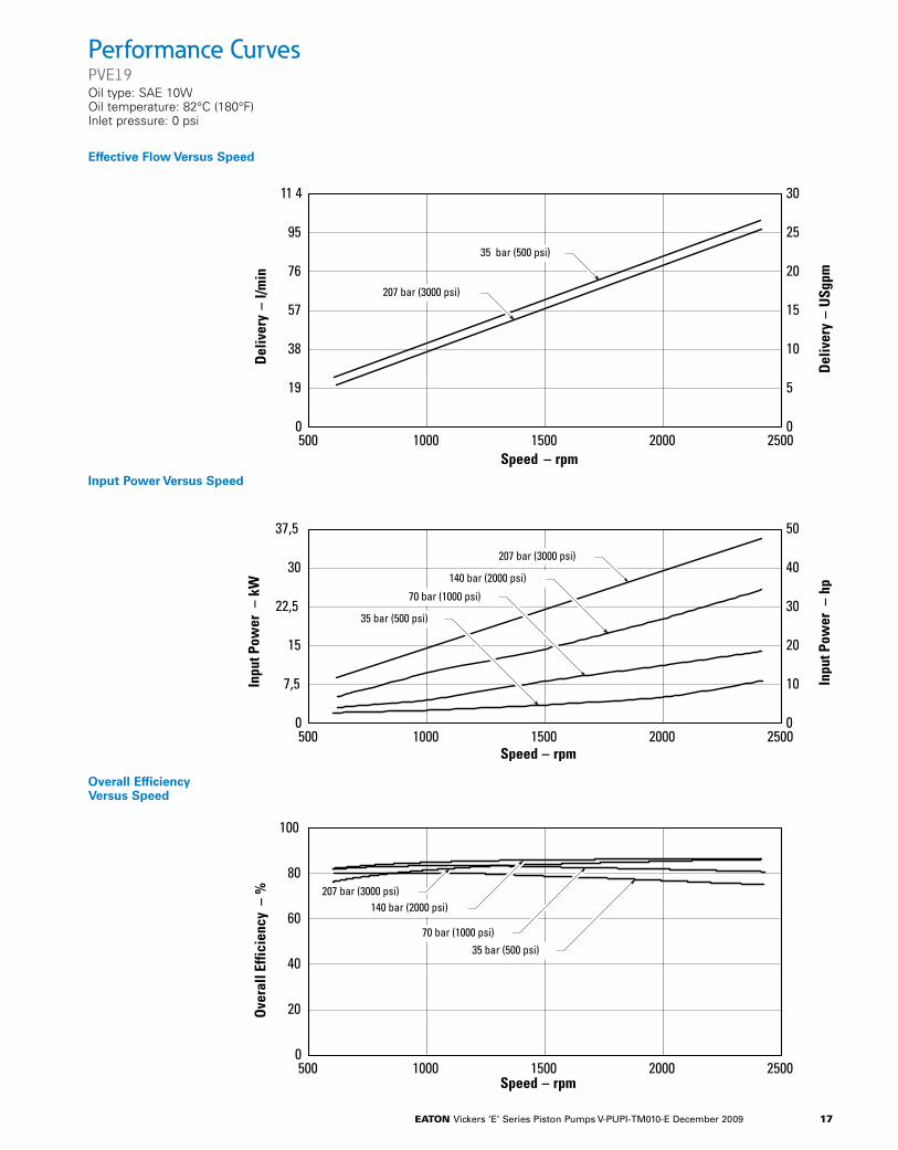
Performance CurvesPVE19Oil type: SAE 10W Oil temperature: 82°C (180°F) Inlet pressure: 0 psi
11 4
95
76
57
38
19
0
5
10
15
20
25
30
500 1000 1500 2000 2500Speed – rpm
Del
iver
y –
l/min
Del
iver
y –
USg
pm
0
30
22,5
15
7,5
0
10
20
30
40
500 1000 1500 2000Speed – rpm
Inpu
t Pow
er –
kW
Inpu
t Pow
er –
hp
0
100
80
60
40
20
500 1000 1500 2000 2500Speed – rpm
Ove
rall
Effic
ienc
y –
%
0
35 bar (500 psi)
207 bar (3000 psi)
207 bar (3000 psi)
140 bar (2000 psi)
70 bar (1000 psi)
35 bar (500 psi)
207 bar (3000 psi)140 bar (2000 psi)
70 bar (1000 psi)35 bar (500 psi)
37,5 50
2500
Effective Flow Versus Speed
Input Power Versus Speed
Overall Efficiency Versus Speed
11 4
95
76
57
38
19
0
5
10
15
20
25
30
500 1000 1500 2000 2500Speed – rpm
Del
iver
y –
l/min
Del
iver
y –
USg
pm
0
30
22,5
15
7,5
0
10
20
30
40
500 1000 1500 2000Speed – rpm
Inpu
t Pow
er –
kW
Inpu
t Pow
er –
hp
0
100
80
60
40
20
500 1000 1500 2000 2500Speed – rpm
Ove
rall
Effic
ienc
y –
%
0
35 bar (500 psi)
207 bar (3000 psi)
207 bar (3000 psi)
140 bar (2000 psi)
70 bar (1000 psi)
35 bar (500 psi)
207 bar (3000 psi)140 bar (2000 psi)
70 bar (1000 psi)35 bar (500 psi)
37,5 50
2500

eaton Vickers ‘E’ Series Piston Pumps V-PUPI-TM010-E December 2009 18
Performance CurvesPVE19Oil type: SAE 10W Oil temperature: 82°C (180°F) Inlet pressure: 0 psi
A.15
11 4
95
76
57
38
19 5
10
15
20
25
30
500 1000 1500 2000 2500Speed – rpm
Del
iver
y – l/
min
Del
iver
y – U
Sgpm
30
22,5
15
7,5
0
10
20
30
40
500 1000 1500 2000Speed – rpm
Inpu
t Pow
er –
kW
Inpu
t Pow
er –
hp
0
100
80
60
40
Ove
rall
Effic
ienc
y –
%
35 bar (500 psi)
186 bar (2700 psi)
186 bar (2700 psi)
140 bar (2000 psi)
70 bar (1000 psi)
35 bar (500 psi)
37,5 50
2500
45 60
500 1000 1500 2000Speed – rpm
2500
50
90
70186 bar (2700 psi)
140 bar (2000 psi)
70 bar (1000 psi)
35 bar (500 psi)
Input Power Versus Speed
Overall Efficiency Versus Speed
A.15
11 4
95
76
57
38
19 5
10
15
20
25
30
500 1000 1500 2000 2500Speed – rpm
Del
iver
y – l/
min
Del
iver
y – U
Sgpm
30
22,5
15
7,5
0
10
20
30
40
500 1000 1500 2000Speed – rpm
Inpu
t Pow
er –
kW
Inpu
t Pow
er –
hp
0
100
80
60
40
Ove
rall
Effic
ienc
y –
%
35 bar (500 psi)
186 bar (2700 psi)
186 bar (2700 psi)
140 bar (2000 psi)
70 bar (1000 psi)
35 bar (500 psi)
37,5 50
2500
45 60
500 1000 1500 2000Speed – rpm
2500
50
90
70186 bar (2700 psi)
140 bar (2000 psi)
70 bar (1000 psi)
35 bar (500 psi)
A.15
11 4
95
76
57
38
19 5
10
15
20
25
30
500 1000 1500 2000 2500Speed – rpm
Del
iver
y – l/
min
Del
iver
y – U
Sgpm
30
22,5
15
7,5
0
10
20
30
40
500 1000 1500 2000Speed – rpm
Inpu
t Pow
er –
kW
Inpu
t Pow
er –
hp
0
100
80
60
40
Ove
rall
Effic
ienc
y –
%35 bar (500 psi)
186 bar (2700 psi)
186 bar (2700 psi)
140 bar (2000 psi)
70 bar (1000 psi)
35 bar (500 psi)
37,5 50
2500
45 60
500 1000 1500 2000Speed – rpm
2500
50
90
70186 bar (2700 psi)
140 bar (2000 psi)
70 bar (1000 psi)
35 bar (500 psi)
Effective Flow Versus Speed
eaton Vickers ‘E’ Series Piston Pumps V-PUPI-TM010-E December 2009 19
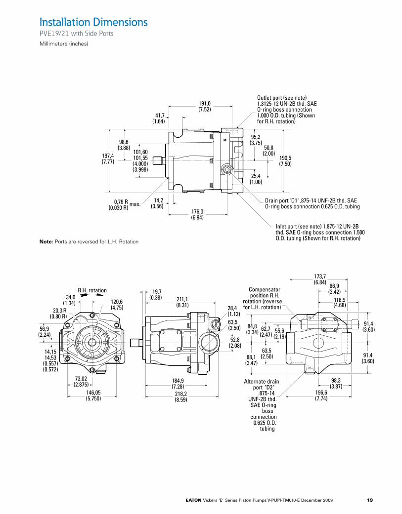
Installation DimensionsPVE19/21 with Side PortsMillimeters (inches)
191,0(7.52)
41,7(1.64)
197,4(7.77)
98,6(3.88)
101,60 101,55
( 4.000)( 3.998)
176,3(6.94)
14,2(0.56)
190,5(7.50)
50,8(2.00)
25,4(1.00)
95,2(3.75)
34,0(1.34)
20,3 R(0.80 R)
14,1514,53
(0.557)(0.572)
56,9(2.24)
120,6(4.75)
146,05(5.750)
73,02(2.875)
R.H. rotation211,1(8.31)
19,7(0.38)
218,2(8.59)
184,9(7.28)
52,8(2.08)
63,5(2.50)
Outlet port (see note)1.3125-12 UN-2B thd. SAEO-ring boss connection1.000 O.D. tubing (Shownfor R.H. rotation)
Drain port "D1" .875-14 UNF-2B thd. SAEO-ring boss connection 0.625 O.D. tubing
Inlet port (see note) 1.875-12 UN-2Bthd. SAE O-ring boss connection 1.500O.D. tubing (Shown for R.H. rotation)
173,7(6.84) 86,9
(3.42)118,9(4.68)
98,3(3.87)
196,6(7.74)
91,4(3.60)
91,4(3.60)
62,7(2.47)
84,8(3.34)
88,1(3.47)
Compensatorposition R.H.
rotation (reversefor L.H. rotation)
Alternate drainport "D2"
.875-14UNF-2B thd.SAE O-ring
bossconnection
0.625 O.D.tubing
max.0,76 R(0.030 R)
28,4(1.12)
55,6(2.19)
63,5(2.50)
Note: Ports are reversed for L.H. Rotation
eaton Vickers ‘E’ Series Piston Pumps V-PUPI-TM010-E December 2009 20
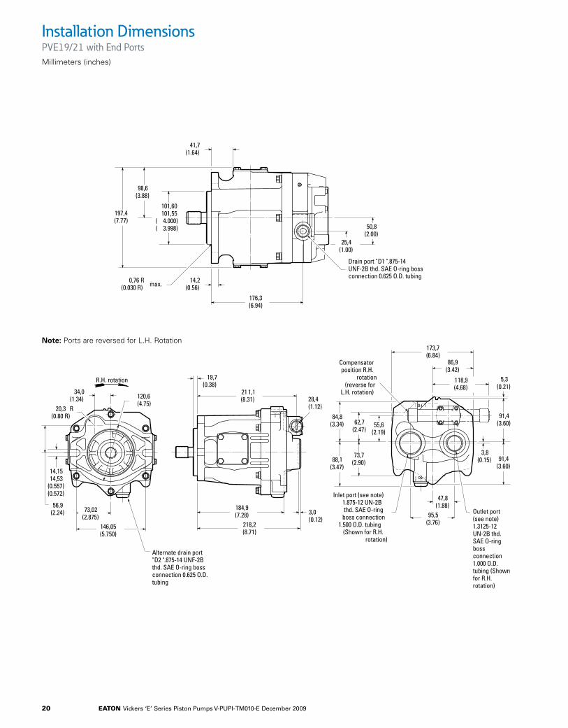
Installation DimensionsPVE19/21 with End PortsMillimeters (inches)
41,7(1.64)
197,4(7.77)
98,6(3.88)
101,60 101,55( 4.000)( 3.998)
176,3(6.94)
14,2(0.56)
50,8(2.00)
25,4(1.00)
34,0(1.34)
20,3 R(0.80 R)
14,1514,53
(0.557)(0.572)
56,9(2.24)
120,6(4.75)
146,05(5.750)
73,02(2.875)
R.H. rotation
21 1,1(8.31)
19,7(0.38)
218,2(8.71)
184,9(7.28)
Inlet port (see note)1.875-12 UN-2Bthd. SAE O-ring
boss connection1.500 O.D. tubing
(Shown for R.H.rotation)
Drain port "D1 " .875-14UNF-2B thd. SAE O-ring bossconnection 0.625 O.D. tubing
Outlet port(see note)1.3125-12UN-2B thd.SAE O-ringbossconnection1.000 O.D.tubing (Shownfor R.H.rotation)
173,7(6.84)
86,9(3.42)
118,9(4.68)
47,8(1.88)
91,4(3.60)
91,4(3.60)
62,7(2.47)
73,7(2.90)
84,8(3.34)
88,1(3.47)
max.0,76 R(0.030 R)
28,4(1.12)
95,5(3.76)
Alternate drain port"D2 " .875-14 UNF-2Bthd. SAE O-ring bossconnection 0.625 O.D.tubing
3,8(0.15)
3,0(0.12)
5,3(0.21)
55,6(2.19)
Compensatorposition R.H.
rotation(reverse for
L.H. rotation)
Note: Ports are reversed for L.H. Rotation

eaton Vickers ‘E’ Series Piston Pumps V-PUPI-TM010-E December 2009 21
ControlsPVE19/21 Adjustable Maximum Displacement Stop
Adjustment
Loosen the locknut on the adjusting rod. Turn the adjusting rod clockwise to decrease maximum pump delivery, or counterclock-wise to increase maximum pump delivery, until the desired setting is obtained. Secure the setting by tight-ening the locknut. To assist initial priming, the manual adjustment control setting must be at least 40% of the maximum flow position.
This control enables maxi-mum pump delivery to be externally adjusted from 25% to 100% (it is not recommended below 50%) while maintaining all the standard features of a pres-sure compensated pump.
219,5(8.64)
279,1(10.99)
93,7(3.69) 55,6
(2.19)
59,7(2.35)
34,0(1.34)
15,0(0.59) max.
Maximum stopadjusting rod
(Approx. 2,22 cc/revchange per turn)
127,8(5.03)
28,4(1.12) Compensator position
for L.H. rotationCompensator position
for R.H. rotation
Locknut 11,2(0.44) across flats
eaton Vickers ‘E’ Series Piston Pumps V-PUPI-TM010-E December 2009 22
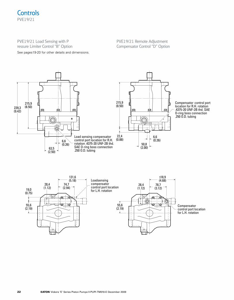
ControlsPVE19/21
PVE19/21 Load Sensing with P ressure Limiter Control “B” OptionSee pages19-20 for other details and dimensions.
PVE19/21 Remote Adjustment Compensator Control “D” Option
63,5(2.50)
6,6(0.26)
239,3(9.42)
55,6(2.19)
19,0(0.75)
215,9(8.50)
74,7(2.94)
131,6(5.18)
28,4(1.12)
Load sensingcompensatorcontrol port locationfor L.H. rotation
Load sensing compensatorcontrol port location for R.H.rotation .4375-20 UNF-2B thd.SAE O-ring boss connection.250 O.D. tubing
215,9(8.50)
22,4(0.88)
Compensator control portlocation for R.H. rotation.4375-20 UNF-2B thd. SAEO-ring boss connection.250 O.D. tubing
50,8(2.00)
6,6(0.26)
55,6(2.19)
118,9(4.68)
78,7(3.12)
Compensatorcontrol port locationfor L.H. rotation
28,4(1.12)

eaton Vickers ‘E’ Series Piston Pumps V-PUPI-TM010-E December 2009 23
ControlsUnloading Valve Control – “E” Option
With the unloading valve control the variable pump will unload at a preset pressure. The pump will maintain this no flow, low pressure (approximately 14 bar (200 psi)) standby condition, until system pressure drops to about 85% of the preset unloading pressure. The pump will then return on stroke and provide full flow until the preset unloading pressure is reached again.
With this control, an efficient accumulator charging circuit is obtained. The pump will provide full flow to fill the accumulator until the maximum charging pressure is reached. The pump then goes to a standby condition until the accumulator pressure drops to 85% of the desired maximum. The accumulator is then recharged as the cycle starts over again.
A separate right angle check valve must be provided to maintain the accumulator hydraulic charge and prevent back flow when the pump is unloaded. The check valve’s internal leakage must not exceed five drops per minute. The control port must be connected to system pressure, downstream of the check valve.
Outlet
Drain
Inlet Check Valve
To load
Unload valvecontrol port
184.9(7.28)
91.4(3.60)
145,5(5.95)
219,4(8.64)
55,6(2.19)
74,7(2.94)
Accumulator unloadingpressure adjustment
Control Port .4375-20UNF-2B thd. SAE O-ring bossconnection .25 OD tubing
Standby pressureadjustment
Outlet
Drain
Inlet Check Valve
To load
Unload valvecontrol port
184.9(7.28)
91.4(3.60)
145,5(5.95)
219,4(8.64)
55,6(2.19)
74,7(2.94)
Accumulator unloadingpressure adjustment
Control Port .4375-20UNF-2B thd. SAE O-ring bossconnection .25 OD tubing
Standby pressureadjustment
Adjustment range
PVE19 100-210 bar (1500-3000 psi) PVE21 100-186 bar
(1500-2700 psi)
Cut-in pressure is 85% of unloading pressure, minimum.
Setting Pressures
1. Back out accumulator un loading pressure adjustment screw to below desired unloading pressure.
2. Adjust desired standby pressure.
3. Set accumulator pressure by screwing in the accumulator unloading adjustment screw. Accumulator recharge (cut-in) pressure is a function of the maximum accumulator pressure and is not adjustable.
4. Check pressure settings and re-adjust if necessary.
Outlet
Drain
Inlet Check Valve
To load
Unload valvecontrol port
184.9(7.28)
91.4(3.60)
145,5(5.95)
219,4(8.64)
55,6(2.19)
74,7(2.94)
Accumulator unloadingpressure adjustment
Control Port .4375-20UNF-2B thd. SAE O-ring bossconnection .25 OD tubing
Standby pressureadjustment

eaton Vickers ‘E’ Series Piston Pumps V-PUPI-TM010-E December 2009 24
Shaft OptionsPVE19/21
SAE "B" involute spline, 13T,16/32 DP flat root side fit
ø25.37 ø25.35( ø0.999)
ø0.998)
28.2227.97(1.111)(1.101)
58.7(2.31)
1.5(0.06) x 45o
6.376.35(0.251)(0.250)
long key31.75(1.250)x
46.0(1.81)
38.10(1.500)
23.75(0.935)
30
1.5(0.06) x 45
50.80(2.000)
33.3(1.31)
ø22.22 ø22.20( ø0.875)( ø0.874)
25.1224.87
(0.989)(0.979)
1.5(0.06) x 45o
44.4(1.75)
33.32(1.312)
41.1(1.62)
6.376.35(0.251)(0.250)
long key22.22(0.875)x
SAE "BB" involute spline,15T, 16/32 DP flat root side fit
18.9(0.74)
1.5(0.06) x 45o
(
No. 02 Shaft: SAE “BB” Straight Keyed No. 08 Shaft: SAE “BB” Splined
SAE "B" involute spline, 13T,16/32 DP flat root side fit
ø25.37 ø25.35( ø0.999)
ø0.998)
28.2227.97(1.111)(1.101)
58.7(2.31)
1.5(0.06) x 45o
6.376.35(0.251)(0.250)
long key31.75(1.250)x
46.0(1.81)
38.10(1.500)
23.75(0.935)
30
1.5(0.06) x 45
50.80(2.000)
33.3(1.31)
ø22.22 ø22.20( ø0.875)( ø0.874)
25.1224.87
(0.989)(0.979)
1.5(0.06) x 45o
44.4(1.75)
33.32(1.312)
41.1(1.62)
6.376.35(0.251)(0.250)
long key22.22(0.875)x
SAE "BB" involute spline,15T, 16/32 DP flat root side fit
18.9(0.74)
1.5(0.06) x 45o
(
No. 05 Shaft: SAE “B” Splined
No. 04 Shaft: Tapered Key shaft
No. 01 Shaft: SAE “B” Straight Keyed
19.05{.750}
1.500:12
3.20{.126}
6.35{.250}
6.35{.250}
69.8{2.75}
61.9{2.44}
ø
25.37 25.35
23.5{.93}
27{1.06}
12.7{.50}
1.5{.06} X 45∞
ø4.09 3.89
.161 .153THRU
.750-16 UNF-2A
}{ .999 .998
}{

eaton Vickers ‘E’ Series Piston Pumps V-PUPI-TM010-E December 2009 25
Thru-drivesPVE19/21 SAE “A” Thru-drivesMillimeters (inches)
.500-13 UNC –2B thd.26,9 (1.06 deep) 8plcs. for 38,1 (1.50)bolt flange
82,67 82,57( 3.253)( 3.251)
142,4 (5.61)
197,4(7.77)
98,6(3.88)
101,60 101,55
( 4.000)( 3.998)
176,3 (6.94)42,1
(1.66)
34,0 (1.34)
20,3 R(0.80 R)
14,1514,53
(0.557)(0.572)
56,9(2.24)
120,6(4.75)
146,05(5.750)
73,02(2.875)
L.H. rotation
45,9(1.81)
242,1(9.53)
Drain port "D1" .875-14UNF-2B thd. SAE O-ringboss connection 0.625O.D. tubing
91,4(3.60)
73,6(2.90)
88.1
Load sensing control port.4375-20 UNF-2B thd. SAE
Oíring boss connection.250 O.D. tubing
Alternate drainport "D2" .875-14
UNF-2B thd.SAE O-ring boss
connection0.625 O.D. tubing
52,4(2.06)
101,6101,5(4.0003.998)
Port 1.00 outletSAE J518 4 boltflange Std. pressureseries (L.H.)
73,02(2.875)
.375-16UNC-2B thd.22,3 (.88) deep4 plcs. D1
84,8(3.34)
84,8(3.34)
(2.09)53,1
184,1 (7.25)
91,9 (3.62)106,3 (4.18)
95,2(3.75)
SAE "A" Mtg flg.
69,8(1.37)
34,9(1.37)
17,8 (.703)35,7 (1.41)
View A – A
Inlet Port–1.50 SAEJ5184 bolt flangestd pressureseries
87,42 87,37( 3.442)( 3.440)
191,2 (7.53)
A
A
Dim."B"
Dim. "D"
Dim. "A"
Dim. "C"
#2 SHAFT – SAE B – B
Coupling
.375-16 UNC2 plcs.18,2 (.72)deep)
(3.47)
PVe 19/21 Sae “a” thru-drives
Thru- DIM. “A” DIM. “B” DIM. “C” Max Torque Rating Coupling shaft Spline Data mm (in.) mm (in.) mm (in.) N.m (In. lbs.) Length Dim “D” mm (in.)AA 9 teeth 16/32DP 50,8 12,7 22,6 58 864224 Flat Root Side Fit (2.00) (0.50) (0.89) (517) 62,7 (2.47) 62,2 (2.45)AB 11 teeth 16/32DP 50,8 14,5 22,6 123 864325 Flat Root Side Fit (2.00) (0.57) (0.89) (1100) 60,9 (2.40) 60,7 (2.39)
Note: Couplings, screws and washers must be ordered separately to mount rear pump. “A” O-ring (AS568-042) is included with each thru-drive pump.
Note: Ports are reversed for R.H. Rotation

eaton Vickers ‘E’ Series Piston Pumps V-PUPI-TM010-E December 2009 26
Thru-drivesPVE19/21 SAE “B” Thru-drivesMillimeters (inches)
84,8(3.34)
57,1 (2.825
Alternate drainport "D2" .875-14
UNF-2B thd.SAE O-ring boss
connection0.625 O.D. tubing
142,4 (5.61)
197,4(7.77)
98,6(3.88)
101,60 101,55
( 4.000)( 3.998)
176,3 (6.94)42,1
(1.66)
34,0 (1.34)
20,3 R(0.80 R)
14,1514,53
(0.557)(0.572)
56,9(2.24)
120,6(4.75)
146,05(5.750)
73,02(2.875)
R.H. rotation
45,9(1.81)
254,7 (10.03)
Drain port "D1" .875-14 UNF-2B thd. SAEO-ring boss connection 0.625 O.D. tubing
91,4(3.60)
Load sensing control port.4375-20 UNF-2B thd. SAE
Oíring boss connection.250 O.D. tubing
101,6101,5(4.0003.998)
D184,8
(3.34)
(2.87)73,0
196,6 (7.74)
146,0 (5.75)
12,0(4.75)
#2 SHAFT – SAE B–B
191,0 (7.52)
95,3(3.75)
95,3(3.75)
Inlet port 1.875 –12 UN–2B thd. SAEO-ring boss connection 1.500 O.D. tubing
137,2(5.40)
95,7(3.77)
9.6(.38)
19,8 (0.78)
12,7 (0.50)
101,67 101,62( 4.003) ( 4.001)
Dim."A"
(3.87)98,3
Outlet port 1.3125-12 UF-2B thd. SAEO-ring boss connection 1.000 O.D. tubing
63,5(2.50)
107,31 107,06( 4.225) ( 4.215)
Coupling(See table)
82,5(3.25)
55,3(2.18)
33,7(1.33)
171,4 (6.75)147,8 (5.82)
85,8 (3.38)11,6
(0.46)
19,0 (0.75)19,05 (0.75)28,5 (1.125) 114,3 (4.50) 28,5 (1.12)
17,27(0.68)
85,85(3.38)
R12,85(0.506)12,73(0.501)
2holes
10,41(0.410)10,29(0.405)
2holes
19,0 (0.75)
PVe 19/21 Sae “B” thru-drives
Thru- Max Torque Rating DIM. “A” Coupling shaft Spline Data N.m (In. lbs.) mm (in.) Length Dim “D” mm (in.)AE Special Eaton 26 tooth 179 10,9 864307 32/64DP Flat Root Side Fit (1587) (0.43) 26T/13T 20,6 475134 (0.81) 26T/15T 24,9 627168 (0.98) 26T/26T
Note: Couplings, screws and washers must be ordered separately to mount rear pump. “A” O-ring (AS568-155) is included with each thru-drive pump. * Total input to front pump must not exceed input shaft limit! Thru shaft tongue maybe less baied on maximum input tongue to front pump.
Note: Ports are reversed for R.H. Rotation

eaton Vickers ‘E’ Series Piston Pumps V-PUPI-TM010-E December 2009 27
Thru-drivesPVE19/21 SAE “B” Thru-drivesMillimeters (inches)
84,8(3.34)
57,1 (2.825
Alternate drainport "D2" .875-14
UNF-2B thd.SAE O-ring boss
connection0.625 O.D. tubing
142,4 (5.61)
197,4(7.77)
98,6(3.88)
101,60 101,55
( 4.000)( 3.998)
176,3 (6.94)42,1
(1.66)
34,0 (1.34)
20,3 R(0.80 R)
14,1514,53
(0.557)(0.572)
56,9(2.24)
120,6(4.75)
146,05(5.750)
73,02(2.875)
R.H. rotation
45,9(1.81)
254,7 (10.03)
Drain port "D1" .875-14 UNF-2B thd. SAEO-ring boss connection 0.625 O.D. tubing
91,4(3.60)
Load sensing control port.4375-20 UNF-2B thd. SAE
Oíring boss connection.250 O.D. tubing
101,6101,5(4.0003.998)
D184,8
(3.34)
(2.87)73,0
196,6 (7.74)
146,0 (5.75)
12,0(4.75)
#2 SHAFT – SAE B–B
191,0 (7.52)
95,3(3.75)
95,3(3.75)
Inlet port 1.875 –12 UN–2B thd. SAEO-ring boss connection 1.500 O.D. tubing
137,2(5.40)
95,7(3.77)
9.6(.38)
19,8 (0.78)
12,7 (0.50)
101,67 101,62( 4.003) ( 4.001)
Dim."A"
(3.87)98,3
Outlet port 1.3125-12 UF-2B thd. SAEO-ring boss connection 1.000 O.D. tubing
63,5(2.50)
107,31 107,06( 4.225) ( 4.215)
Coupling(See table)
82,5(3.25)
55,3(2.18)
33,7(1.33)
171,4 (6.75)147,8 (5.82)
85,8 (3.38)11,6
(0.46)
19,0 (0.75)19,05 (0.75)28,5 (1.125) 114,3 (4.50) 28,5 (1.12)
17,27(0.68)
85,85(3.38)
R12,85(0.506)12,73(0.501)
2holes
10,41(0.410)10,29(0.405)
2holes
19,0 (0.75)
Thru-drive Pump Support Bracket
An optional support bracket should be used when a heavy second pump is mounted to a thru-drive PVE19/21. The support bracket (627179), two screws (199740), and two washers (427700) must be ordered separately.

eaton Vickers ‘E’ Series Piston Pumps V-PUPI-TM010-E December 2009 28
Application Data
Fluid Cleanliness
Proper fluid condition is essential for long and satisfactory life of hydraulic components and systems. Hydraulic fluid must have the correct balance of cleanliness, materials, and ad ditives for protection against wear of components, elevated viscosity, and inclusion of air. Fluid contamination levels according to ISO4406 should not exceed 21/18/13 for PVE Piston pumps.
Essential information on the correct methods for treating hydraulic fluid is included in Eaton publication 561 “Eaton Guide to Systemic Contamina tion Control” available from your local Eaton distributor or by contacting Eaton Hydraulics. Recommendations on filtration and the selection of products to control fluid condition are included in 561.
Recommended cleanliness levels, using petroleum oil under common conditions, are based on the highest fluid pressure levels in the system and are coded in the chart below. Fluids other than petroleum, severe service cycles, or temperature extremes are cause for adjustment of these cleanliness codes. See Eaton publication 561 for exact details.
Eaton products, as any com ponents, will operate with apparent satisfaction in fluids with higher cleanliness codes than those described. Other manufacturers will often recommend levels above those specified. Experience has shown, however, that life of any hydraulic component is shortened in fluids with higher cleanliness codes than those listed below. These codes have been proven to provide a long, trouble-free service life for the products shown, regardless of the manufacturer.
Fire resistant fluids
Water glycol, phosphate ester and polyol ester fluids may be used with PVE pumps. With the PVE012 and PVE19, system pressure and input speed should not exceed 140 bar (2000 psi) and 1800 r/min.
System temperature should not exceed 54°C (130°F). Inlet vacuum should not exceed 101,6 millibar (3 in. Hg.).
Hydraulic fluids and temperature ranges
Use antiwear hydraulic oil, or automotive type crankcase oil designations SC, SD, SE or SF per SAE J183FEB80.
Select a viscosity grade that will allow optimum viscosity, between 40 cSt (180 SUS) and 16 cST (80 SUS), to be achieved within the optimum performance envelope shown.
For further information, see Eaton Hydraulic Hints and Trouble Shooting Guide.
Ordering procedure
Order PVE pumps by the full model designation. Pump displacement, mounting flange type, direction of rotation, pump configuration, shaft end type, seals, pressure adjustment range, specific control functions are all specified in the full model code.

eaton Vickers ‘E’ Series Piston Pumps V-PUPI-TM010-E December 2009 29
Notes

EatonHydraulics Group USA14615 Lone Oak RoadEden Prairie, MN 55344USATel: 952-937-9800Fax: 952-294-7722www.eaton.com/hydraulics
EatonHydraulics Group EuropeRoute de la Longeraie 71110 MorgesSwitzerlandTel: +41 (0) 21 811 4600Fax: +41 (0) 21 811 4601
Eaton Hydraulics Group Asia PacificEaton Building4th Floor, No. 3 Lane 280 Linhong Rd. Changning DistrictShanghai 200335ChinaTel: (+86 21) 5200 0099Fax: (+86 21) 5200 0400
© 2009 Eaton CorporationAll Rights Reserved Printed in USADocument No. V-PUPI-TM010-ESupersedes V-PP-MC-001-E December 2009